technical training em/emc monitor - praftec
TRANSCRIPT

PRAF MICROCOMPUTER TECHNOLOGIES LTD. P.O.B. 7209, Holon 5817101, Israel Tel.: +972-3-5031045, Fax: +972-3-5031046 http://www.praftec.com E-mail: [email protected]
POLAR MOHR is a registered trade mark of Polar-Mohr Maschinenvertriebsgesellschaft GmbH & Co. KG
DOC REF: (Reproduction)
POLAR-191030-EM-EMC-MON-TECHNICAL-TRAINING Mon gb 01 04.04.2005
PRAF Microcomputer Technologies Ltd. Confidential Company Property.POLAR-191030-EM-EMC-MON-TECHNICAL-TRAINING Page 1 of 62 For internal use only.
Technical Training
EM/EMC MONITOR
Setup of Control Unit
Power Supply
Description of Plug-in Boards
List of Error Messages – Service Information

PRAF MICROCOMPUTER TECHNOLOGIES LTD. P.O.B. 7209, Holon 5817101, Israel Tel.: +972-3-5031045, Fax: +972-3-5031046 http://www.praftec.com E-mail: [email protected]
POLAR MOHR is a registered trade mark of Polar-Mohr Maschinenvertriebsgesellschaft GmbH & Co. KG
DOC REF: (Reproduction)
POLAR-191030-EM-EMC-MON-TECHNICAL-TRAINING Mon gb 01 04.04.2005
PRAF Microcomputer Technologies Ltd. Confidential Company Property.POLAR-191030-EM-EMC-MON-TECHNICAL-TRAINING Page 2 of 62 For internal use only.
Table of contents
Monitor control unit ………………………………………………………………………………………… 3
Arrangements of boards in CU.……..……………………………………………………………………… 4
Setup of control systems and EM/EMC Monitor block diagram ……………………………………… 5
Control components and their applications ……………………………………………………………… 6
Program versions and their use EM Monitor …………………………………………………………… 7
Program versions and their use EMC Monitor …………………………………………………………… 8
Details about program V5.0 (Drupa)………………………………………………………………………. 9
Except from IP2/97 (Reduction of program versions) ………………………………………………… 10
Voltage supply (Power Module) …………………………………………………………………………… 11
Control voltages………..……………………..…………………………………………………………….. 12
Power Supply (PS) plug-in board…….……………………………………………………………………. 13
Central Processor (CP1) plug-in board…………………………………………………………………… 15
Positioning Interface (PI). …………………………………………………………………………………. 15
Positioning Interface (PI) plug-in board.…………………………………………………………………… 17
Linear measuring system…………………………………………………………………………………… 18
Interchangeable memory and Motor Control Unit (MCM unit).…………………………………………. 20
Cutting circuit (SK)………………………………………………………………………………………….. 21
Cutting circuit (SK) plug-in board ………………………………………………………………………… 22
Cutting circuit (SK) with two-channel hydraulic system…………………………………………………. 23
Light barrier (LS)…………………………………………………………………………………….………. 24
Video Controller (VID) and Monitor (CRT)……………………………………………………….………. 25
Keyboard Computer (KC) and control unit (BTM) ……………………………………………………… 25
Timer board (CLK) and PMS card………………………………………………………………………… 27
New knife change….……………………………………………………………………………………….. 27
Circuit diagrams…………………………………………………………………………………………….. 29
Parts lists…………………………………………………………………………………………………….. 37
Addendum
List of error messages and service information

PRAF MICROCOMPUTER TECHNOLOGIES LTD. P.O.B. 7209, Holon 5817101, Israel Tel.: +972-3-5031045, Fax: +972-3-5031046 http://www.praftec.com E-mail: [email protected]
POLAR MOHR is a registered trade mark of Polar-Mohr Maschinenvertriebsgesellschaft GmbH & Co. KG
DOC REF: (Reproduction)
POLAR-191030-EM-EMC-MON-TECHNICAL-TRAINING Mon gb 01 04.04.2005
PRAF Microcomputer Technologies Ltd. Confidential Company Property.POLAR-191030-EM-EMC-MON-TECHNICAL-TRAINING Page 3 of 62 For internal use only.
Control Panel Monitor

PRAF MICROCOMPUTER TECHNOLOGIES LTD. P.O.B. 7209, Holon 5817101, Israel Tel.: +972-3-5031045, Fax: +972-3-5031046 http://www.praftec.com E-mail: [email protected]
POLAR MOHR is a registered trade mark of Polar-Mohr Maschinenvertriebsgesellschaft GmbH & Co. KG
DOC REF: (Reproduction)
POLAR-191030-EM-EMC-MON-TECHNICAL-TRAINING Mon gb 01 04.04.2005
PRAF Microcomputer Technologies Ltd. Confidential Company Property.POLAR-191030-EM-EMC-MON-TECHNICAL-TRAINING Page 4 of 62 For internal use only.
Arrangement of plug-in cards in the CU

PRAF MICROCOMPUTER TECHNOLOGIES LTD. P.O.B. 7209, Holon 5817101, Israel Tel.: +972-3-5031045, Fax: +972-3-5031046 http://www.praftec.com E-mail: [email protected]
POLAR MOHR is a registered trade mark of Polar-Mohr Maschinenvertriebsgesellschaft GmbH & Co. KG
DOC REF: (Reproduction)
POLAR-191030-EM-EMC-MON-TECHNICAL-TRAINING Mon gb 01 04.04.2005
PRAF Microcomputer Technologies Ltd. Confidential Company Property.POLAR-191030-EM-EMC-MON-TECHNICAL-TRAINING Page 5 of 62 For internal use only.
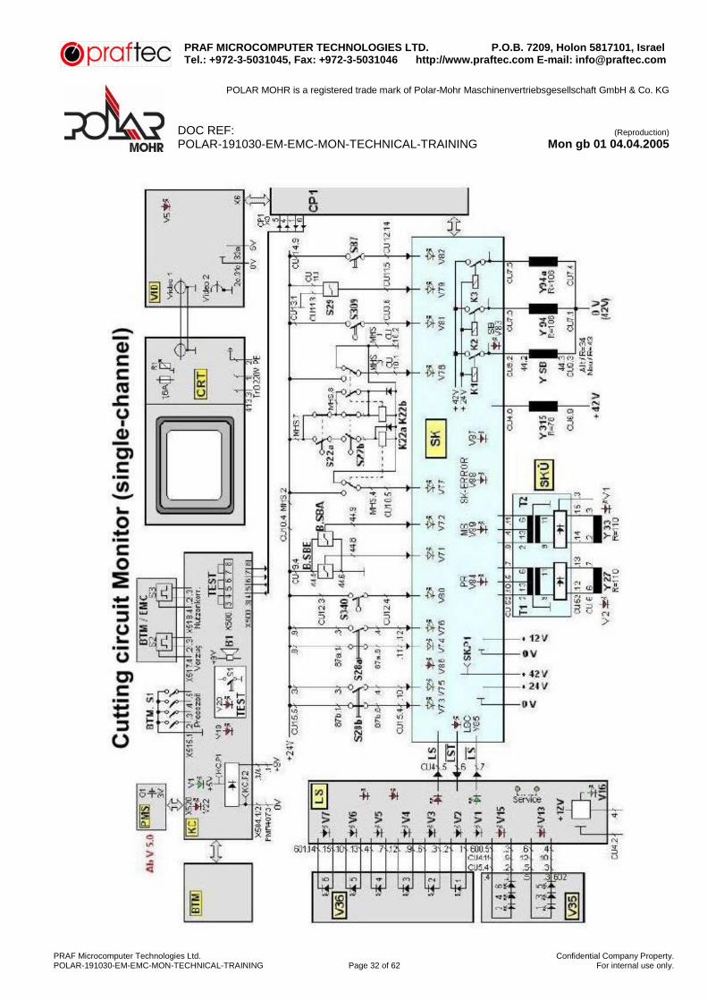
Setup of control unit
The block diagram of the POLAR EMC MONITOR illustrates the structural setup of the control system. The 16-bit CP1 (Central Processor) computer board is the ”heart” of the control system. All the other plug-in cards in the electrical installation facility beneath the machine front table are linked via two independent bus systems with the CP1. The exchange of data with the keyboard computer (KC) on the control panel is performed via serial interface.
Block diagram of EM/EMC - Monitor

PRAF MICROCOMPUTER TECHNOLOGIES LTD. P.O.B. 7209, Holon 5817101, Israel Tel.: +972-3-5031045, Fax: +972-3-5031046 http://www.praftec.com E-mail: [email protected]
POLAR MOHR is a registered trade mark of Polar-Mohr Maschinenvertriebsgesellschaft GmbH & Co. KG
DOC REF: (Reproduction)
POLAR-191030-EM-EMC-MON-TECHNICAL-TRAINING Mon gb 01 04.04.2005
PRAF Microcomputer Technologies Ltd. Confidential Company Property.POLAR-191030-EM-EMC-MON-TECHNICAL-TRAINING Page 6 of 62 For internal use only.
Control components and their use
Title Application Machine type PM Power Module Standard Version EM/EMC PS Power Supply Standard Version EM/EMC CP1 Central Processor Standard Version EM/EMC PI Positioning Interface Standard Version EM/EMC VID Video Controller Standard Version EM/EMC CRT VDU Standard Version EM/EMC SK Cutting circuit Standard Version EM/EMC MCM Motor Control Standard Version EM/EMC KC Keyboard Computer Standard Version EM/EMC BTM Control panel Standard Version EMC BTM Control panel Standard Version EM LS Light barrier Standard Version EM/EMC CLK Clock Standard Version EMC SDS Automatic start-delta switch
(not on model 92) EM/EMC
CFM Special function Autotrim, gripper Monitor Connection to TRB 3BL, Programmable outputs (“EXT” key)
EM/EMC
SHM Special Hydraulic system Lifts that can be lowered Monitor Side gauges, Backgauge lock
EM/EMC
DNF Swivel/tilting backgauge Swivel backgauge, titling backgauge EMC SER Special electr. System Swivel backgauge, titling backgauge
Relay plate EMC
Servo Servo control Optimized High-speed backgauge
EMC
PDR Clamping presuure regulation Automatic Clamping presuure regulation
EMC
PMS Polar – Memory – Additional System program memory
EM/EMC

PRAF MICROCOMPUTER TECHNOLOGIES LTD. P.O.B. 7209, Holon 5817101, Israel Tel.: +972-3-5031045, Fax: +972-3-5031046 http://www.praftec.com E-mail: [email protected]
POLAR MOHR is a registered trade mark of Polar-Mohr Maschinenvertriebsgesellschaft GmbH & Co. KG
DOC REF: (Reproduction)
POLAR-191030-EM-EMC-MON-TECHNICAL-TRAINING Mon gb 01 04.04.2005
PRAF Microcomputer Technologies Ltd. Confidential Company Property.POLAR-191030-EM-EMC-MON-TECHNICAL-TRAINING Page 7 of 62 For internal use only.
Program Versions and their use
If the CP1 or VID plug-in card needs to be replaced because of a defect, please remember that the card must be compatible with the machine equipment. Program versions with addition “S” can only be used with the “optimized high-speed backgauge” optional equipment. (only on EMC)
Board KC 0185 id. No.: 020111 can only be used with versions V1.0-V4.1. As of version V5.0 the board KC V2.1 with id. No. 023831 has been used. As of version V6.0 the board KC V2.2 with id. No. 023832 has been used.
Table of the existing EM – MONITOR program versions and all the available combinations
CP1 Video Monitor Prog. Version Text Version Id. No Prog. Version Id. No. Monochrome Color V2.0 T06 EG 020930 V3.0 (2.0) 020620 “ V2.0 T07 Skand. 020931 V3.0 (2.0) 020621 “ “ V3.1 T08 EG 020932 V3.0 (2.0) 020620 “ V3.1 T09 Skand. 020933 V3.0 (2.0) 020621 “ “
CP Version no longer available = see IP2/97 = V4.0 T08 EG 023770 V3.0 020622 “ “ V4.0 T09 Skand. 023780 V3.0 020622 “ “ V4.1 T08 EG 023771 V3.0 020622 “ “ V4.1 T09 Skand. 023781 V3.0 020622 “ ” V4.2 T08 EG 023772 V3.0 020622 “ “ V4.2 T09 Skand. 023782 V3.0 020622 “ “ V4.3 T11A EG 023773 V3.0 020622 “ “ V4.3 T11B Skand. 023783 V3.0 020622 “ “ V4.4 T11a 023774 V3.0 020662 “ “ V4.4 T12b 023784 V3.0 020662 “ “
As of V5.0 with PMS Card and KC V2.1 V5.0 T08 EG 024350 V3.0 020622 “ “ V5.1 T08 EG 024351 V3.0 020622 “ “ V5.1 T09 Skand. 024401 V3.0 020622 “ “
As of V6.0 with KC V2.2 V6.0 T11 024860 V3.0 020622 “ “ V6.2 024861 V3.0 020622 “ “

PRAF MICROCOMPUTER TECHNOLOGIES LTD. P.O.B. 7209, Holon 5817101, Israel Tel.: +972-3-5031045, Fax: +972-3-5031046 http://www.praftec.com E-mail: [email protected]
POLAR MOHR is a registered trade mark of Polar-Mohr Maschinenvertriebsgesellschaft GmbH & Co. KG
DOC REF: (Reproduction)
POLAR-191030-EM-EMC-MON-TECHNICAL-TRAINING Mon gb 01 04.04.2005
PRAF Microcomputer Technologies Ltd. Confidential Company Property.POLAR-191030-EM-EMC-MON-TECHNICAL-TRAINING Page 8 of 62 For internal use only.
Table of the EMC – MONITOR program versions and all the available combinations
CP1 Video Monitor
Prog. Version Text Version Id. No Prog. Vesrion Id. No. Monochrome Color V1.1 (1.0) T01-T03 EG 020150 V1.1 (1.0) 020131 “ V1.1 (1.0) T02 Skand 020150 V1.1 (1.0) 020131 “ V2.0 T06 EG 020151 V3.0 (2.0) 020620 “ V2.0 T06 EG 020151 V3.0 (2.0) 020621 “ “ V2.0 T07 Skand. 020152 V3.0 (2.0) 020620 “ V2.0 T07 Skand. 020152 V3.0 (2.0) 020621 “ “ V3.1 T08 EG 020155 V3.0 (2.0) 020620 “ V3.1 T08 EG 020155 V3.0 (2.0) 020621 “ “ V3.1 T09 Skand. 020156 V3.0 (2.0) 020620 “ V3.1 T09 Skand. 020156 V3.0 (2.0) 020621 “ “ V3.1-S T08 EG 020157 V3.0 (2.0) 020620 “ V3.1-S T09 Skand. 020157 V3.0 (2.0) 020621 “ “ V3.1-S T08 EG 020158 V3.0 (2.0) 020620 “ V3.1-S T09 Skand. 020158 V3.0 (2.0) 020621 “ “
CP Version no longer available = see IP2/97 = V4.0 T08 EG 023590 V3.0 020622 “ “ V4.0 T09 Skand. 023900 V3.0 020622 “ “ V4.0-S T08 EG 023610 V3.0 020622 “ “ V4.0-S T09 Skand. 023620 V3.0 020622 “ “ V4.1 T08 EG 023591 V3.0 020622 “ “ V4.1 T09 Skand. 023601 V3.0 020622 “ ” V4.1-S T08 EG 023611 V3.0 020622 “ “ V4.1-S T09 Skand. 023621 V3.0 020622 “ “ V4.2 T08 EG 023592 V3.0 020622 “ “ V4.2 T09 Skand. 023602 V3.0 020622 “ “ V4.2-S T08 EG 023612 V3.0 020622 “ “ V4.2-S T09 Skand. 023622 V3.0 020622 “ “ V4.3 T11A EG 023593 V3.0 020622 “ “ V4.3 T11B Skand. 023603 V3.0 020622 “ “ V4.3-S T11A EG 023613 V3.0 020622 “ “ V4.3-S T11B Skand. 023623 V3.0 020622 “ “ V4.4 T12A EG 023594 V3.0 020662 “ “ V4.4 T12B Skand. 023604 V3.0 020662 “ “
As of V5.0 with PMS Card and KC V2.1 V5.0 T08 024330 V3.0 020622 “ “ V5.0-S T08 024340 V3.0 020622 “ “ V5.1 T08 EG 024331 V3.0 020622 “ “ V5.1 T09 Skand. 024411 V3.0 020622 “ “ V5.1-S T08 EG 024341 V3.0 020622 “ “ V5.1-S T09 Skand. 024321 V3.0 020622 “ “
As of V6.0 with KC V2.2 V6.0 T11 024840 V3.0 020622 “ “ V6.0-S T11 024850 V3.0 020622 “ “ V6.2 024841 V3.0 020622 “ “

PRAF MICROCOMPUTER TECHNOLOGIES LTD. P.O.B. 7209, Holon 5817101, Israel Tel.: +972-3-5031045, Fax: +972-3-5031046 http://www.praftec.com E-mail: [email protected]
POLAR MOHR is a registered trade mark of Polar-Mohr Maschinenvertriebsgesellschaft GmbH & Co. KG
DOC REF: (Reproduction)
POLAR-191030-EM-EMC-MON-TECHNICAL-TRAINING Mon gb 01 04.04.2005
PRAF Microcomputer Technologies Ltd. Confidential Company Property.POLAR-191030-EM-EMC-MON-TECHNICAL-TRAINING Page 9 of 62 For internal use only.
Extensions to Monitor machines (Drupa 90 version)
1. Program extension to V5.0 or V5.1 2. PMS System
As of machine 155 EM – EMC Monitor no. 6021001 (April 1990) the program V5.0 was employed on CP1. Shortly after that, this program was modified to version V5.1. This change involves the boards CP1, KC, BTM and PI.
EM – Monitor
CP1 Video V5.0 T08 024350 V3.0 020622 Monochrome Color V5.0 T09 024400 V3.0 020622 Monochrome Color V5.1 T08 024351 V3.0 020622 Monochrome Color V5.1 T09 024401 V3.0 020622 Monochrome Color
EMC – Monitor
CP1 Video V5.0 T08 024330 V3.0 020622 Monochrome Color V5.0 T09 024410 V3.0 020622 Monochrome Color V5.0-S T08 024341 V3.0 020622 Monochrome Color V5.0-S T05 ->T09 024421 V3.0 020622 Monochrome Color V5.1 T08 024331 V3.0 020622 Monochrome Color V5.1 T09 024411 V3.0 020622 Monochrome Color V5.1-S T08 024341 V3.0 020622 Monochrome Color V5.1-S T09 024421 V3.0 020622 Monochrome Color
This modification of program versions V5.0 and V5.1 cause the following changes to the previously used control boards.
1.1 The PI board, id. No. 024080, is no longer equipped with a slot for interchangeable memories, because the program memories are now integrated into the CP1 computer board. All the other functions on the PI board remain unchanged. For service purposes, the former PI boards can be used too.
1.2 Keyboard controller KC, id. No. 023830 is a new development. Apart from the well known
features of these boards a new slot for the PMS card has been installed. The additional red colored LED V22 which is designated R/W (Read/Write) indicates the reading and writing functions of the PMS card. The mechanics of the KC has also been changed. – see BTM –
1.3 The BTM control unit, id. No. 023810 (EMC), 024360 (EM), has also been modified and can
therefore no longer be used on machines with the older program versions. The complete keypad has been displaced about 10 mm downward in order to have enough space for 10 additional function keys, which are not used at the moment, however. Please note! The BT – DNF has also been mechanically changed.
2. The PMS card, POLAR Memory System, id. No. 228243, is a check-card size memory card offered as an optional unit. This PMS card is a 3V Lithium battery-backed RAM which has capacity of 99 programs. This memory serves to transfer programs from machine to machine, from computer to machine or simply to store cutting programs. It is no main memory comparable to our RSP interchangeable memory.

PRAF MICROCOMPUTER TECHNOLOGIES LTD. P.O.B. 7209, Holon 5817101, Israel Tel.: +972-3-5031045, Fax: +972-3-5031046 http://www.praftec.com E-mail: [email protected]
POLAR MOHR is a registered trade mark of Polar-Mohr Maschinenvertriebsgesellschaft GmbH & Co. KG
DOC REF: (Reproduction)
POLAR-191030-EM-EMC-MON-TECHNICAL-TRAINING Mon gb 01 04.04.2005
PRAF Microcomputer Technologies Ltd. Confidential Company Property.POLAR-191030-EM-EMC-MON-TECHNICAL-TRAINING Page 10 of 62 For internal use only.
Excerpt from IP2/97
Reduction of program versions for EM/EMC Monitor machines The CP1 boards listed below, which are meant for machines without PMS card, replace the boards with software versions V1.1 to V3.1-S, inclusive. The reduction of variants achieved in this way makes stock keeping easier and organization clearer. For any conversion, please observe the compatibility of the Video card you use in connection with the corresponding program status of the CP1. If the machine still contains a European standard size video PC Board, remember to remove the guide tie in the CU before installing the new video board (double European standard size). Please return any defective or replaced boards to our spare parts department.
Current program versions of CP1 boards (which replace the versions V1.1 to V3.1-S inclusively)
Machine Board Version Text Id. No. Board Id. No. Comment EMC CP1 V4.4 T12a 023594 Video 2 020622 Color, Monochrome EMC CP1 V4.4 T12b 023604 Video 2 020622 Color, Monochrome EM CP1 V4.4 T12a 023774 Video 2 020622 Color, Monochrome EM CP1 V4.4 T12b 023784 Video 2 020622 Color, Monochrome
Text T12a for program version V4.4 Text T12b for program version V4.4 1 = GERMAN D 1 = GERMAN D 2 = ENGLISH GB 2 = ENGLISH GB 3 = FRENCH F 3 = FRENCH F 4 = SPANISH E 4 = TURKISH TR 5 = ITALIAN I 5 = DANISH DK 6 = PORTUGESE P 6 = NORDWEGIAN N 7 = DUTCH NL 7 = SWEDISH S 8 = JAPANISE J 8 = FINNISH SF
As of now all the CP1 boards which are returned for repair will be retrofitted to program status V4.4 or more recent, or replaced by new boards of the relevant program status. If a new graphics card is also necessary for the conversion of the machine at the customer’s please order this card separately.

PRAF MICROCOMPUTER TECHNOLOGIES LTD. P.O.B. 7209, Holon 5817101, Israel Tel.: +972-3-5031045, Fax: +972-3-5031046 http://www.praftec.com E-mail: [email protected]
POLAR MOHR is a registered trade mark of Polar-Mohr Maschinenvertriebsgesellschaft GmbH & Co. KG
DOC REF: (Reproduction)
POLAR-191030-EM-EMC-MON-TECHNICAL-TRAINING Mon gb 01 04.04.2005
PRAF Microcomputer Technologies Ltd. Confidential Company Property.POLAR-191030-EM-EMC-MON-TECHNICAL-TRAINING Page 11 of 62 For internal use only.
Power supply
Power Module (PM) The Power Module accommodates the power supply components for the machine control system and includes the main distribution board (PMD), fuse board (PMF), control transformer and rectifier component (PMR). The three-phase lines from the main and (automatic) star-delta switch are protected by three fuses of 10 amps, each, in the main distributor. Behind these fuses, the backgauge drive motor, blower motor, fluorescent lamp for table illumination, and the control transformer are connected. The transformer is switched on via relay K304 on the main distributor. The relay is controlled by the green “Control voltage ON“ button on the right top of the front panel when the (automatic) star-delta switch is changed over to the “delta“ position. When the machine is switched off by pressing the button – 292 – “0“ relay K304 drops out and turns the transformer off. (see circuit diagram 115 EMC 3102 a/c circuit 2 - 24 as well as 45 - 49) Adaptation of the control voltage to varying mains voltages can be carried out on the main distributor. The primary circuit of the transformer can be operated with voltages of 180V to 260 V which are supplied either between two phases (220 V position) or between a phase and the neutral (380 V position).

PRAF MICROCOMPUTER TECHNOLOGIES LTD. P.O.B. 7209, Holon 5817101, Israel Tel.: +972-3-5031045, Fax: +972-3-5031046 http://www.praftec.com E-mail: [email protected]
POLAR MOHR is a registered trade mark of Polar-Mohr Maschinenvertriebsgesellschaft GmbH & Co. KG
DOC REF: (Reproduction)
POLAR-191030-EM-EMC-MON-TECHNICAL-TRAINING Mon gb 01 04.04.2005
PRAF Microcomputer Technologies Ltd. Confidential Company Property.POLAR-191030-EM-EMC-MON-TECHNICAL-TRAINING Page 12 of 62 For internal use only.
The control transformer generates the following voltages on the secondary windings:
Secondary voltage Application PFM Fuse ~32 VAC PS plug-in board +5 V, +24 V and +12 V F1 = 6.3 A ~11.5 VAC +9 V for control unit and keyboard computer F2 = 4.0 A ~12.5 VAC Cutting-line indicator lamp F3 = 4.0 A ~42 VAC 42 VDC for magnets (except for Y27 + Y33) F4 = 6,3 A ~12.5 VAC Cutting-line indicator lamp F5 = 4.0 A ~15 VAC Not assigned F6 ~42 VAC 42 V control voltage for contactors of backgauge drive motor F7 = 1.0 A ~20 VAC Not assigned F8 ~30 VAC Fixomat ~15 VAC Fixomat
The 1 Amp fine-wire fuse for the 32 VAC blower motors is accommodated on the CUM unit (top right).
Control voltages In order to operate the control system the Power Supply (PS) board generates stabilized DC voltages of +5 V, +12 V and +24 V, respectively. The Keyboard Computer (KC) and control unit (BTM) module is supplied with a voltage of +9 VDC from the Power Module (PM). The solenoid valves and lifting magnets in the machine are energized through an unstabilized DC voltage of +42 V (except Y27 and Y33). At the measuring socket on the bottom edge of the SK board you can measure the stabilized voltage of +42 VDC.
In unloaded condition the value is approximately 55 VDC (consequently, no magnet is energized)

PRAF MICROCOMPUTER TECHNOLOGIES LTD. P.O.B. 7209, Holon 5817101, Israel Tel.: +972-3-5031045, Fax: +972-3-5031046 http://www.praftec.com E-mail: [email protected]
POLAR MOHR is a registered trade mark of Polar-Mohr Maschinenvertriebsgesellschaft GmbH & Co. KG
DOC REF: (Reproduction)
POLAR-191030-EM-EMC-MON-TECHNICAL-TRAINING Mon gb 01 04.04.2005
PRAF Microcomputer Technologies Ltd. Confidential Company Property.POLAR-191030-EM-EMC-MON-TECHNICAL-TRAINING Page 13 of 62 For internal use only.
Description of plug-in boards
Power Supply (PS)
The Power Supply board (PS) provides three stabilized voltages:
+5 VDC, Tolerance: 5.08 - 5.12 V +12 VDC, Tolerance: 11.4 - 12.6 V +24 VDC, Tolerance: 23.7 - 24.3 V
Each voltage is assigned a green LED and a measuring socket on the front of the board.
These voltages are not adjustable. In order to ensure a defined start of the control system after the control voltage has been connected the board generates a reset signal, which can be indicated by the red LED V3. The LED is usually off during operation. It only lights briefly when the control voltage is turned on and off.

PRAF MICROCOMPUTER TECHNOLOGIES LTD. P.O.B. 7209, Holon 5817101, Israel Tel.: +972-3-5031045, Fax: +972-3-5031046 http://www.praftec.com E-mail: [email protected]
POLAR MOHR is a registered trade mark of Polar-Mohr Maschinenvertriebsgesellschaft GmbH & Co. KG
DOC REF: (Reproduction)
POLAR-191030-EM-EMC-MON-TECHNICAL-TRAINING Mon gb 01 04.04.2005
PRAF Microcomputer Technologies Ltd. Confidential Company Property.POLAR-191030-EM-EMC-MON-TECHNICAL-TRAINING Page 14 of 62 For internal use only.
Central Processor (CP1)
The 16-bit computer board determines all the machine cycles and operating features through the EPROM-stored processor program. The remaining plug-in cards are connected to the computer by means of two separate bus systems. The front side is equipped with four connectors for serial interfaces, where the keyboard computer, the printer and the peripheral units can be connected. Battery-buffered RAM components serve to store the variable machine data (e.g. brake afterrun, most recent program and step numbers, cut counter, etc.). The relevant lithium-type 3.5 V battery is accommodated on the board. The battery voltage must not drop below 3.0 V. When the pushbutton on the front side of the board is pressed, a computer reset is triggered which is similar to turning off/on the control voltage again. While the machine is in operation the LED in this button is lit and indicates that the microprocessor on the board is working. On those boards which are delivered as spare parts the lithium battery is taken off to prevent any unnecessary discharge. As of program version V5.0 (see page 07) the program memories A and B are integrated into the CP1 board! It has a capacity of 99 programs with 1528 memory locations per memory.

PRAF MICROCOMPUTER TECHNOLOGIES LTD. P.O.B. 7209, Holon 5817101, Israel Tel.: +972-3-5031045, Fax: +972-3-5031046 http://www.praftec.com E-mail: [email protected]
POLAR MOHR is a registered trade mark of Polar-Mohr Maschinenvertriebsgesellschaft GmbH & Co. KG
DOC REF: (Reproduction)
POLAR-191030-EM-EMC-MON-TECHNICAL-TRAINING Mon gb 01 04.04.2005
PRAF Microcomputer Technologies Ltd. Confidential Company Property.POLAR-191030-EM-EMC-MON-TECHNICAL-TRAINING Page 15 of 62 For internal use only.
Positioning Interface (PI)
The Positioning Interface board includes all the assembly groups, which are required for the backgauge movement:
- counter chain for forward and backward pulses of the linear measuring system - preselector for setting the reference position - inputs of the single-hand control switches (S10, S14, S18) - inputs of the table limit switches - outputs of the table motor and brake lifting solenoid controls - slots for the RSP memories (only on V1.0 to V4.4)
The S7 selection switch serves to preset the preferred language and measuring unit to be used after the machine is turned on, for instance when the battery has been replaced and the data on the CP1 board has been lost. The counter monitor can be connected to the three plugs A, B, C located on the PI board. The PI boards as of id. No. 020141 are no longer furnished with these 3 plugs, because the counter chain is integrated in a special module (Gate Array). The V16 and V17 LED’s have also been omitted. As of CP1 Version V5.0 we employ the PI board with id. No. 024080. The slots for the interchangeable memory have been omitted. For test purposes the board can also be employed with older CP1 versions.
Setting the preselector switch S7 (only on program versions V1.0 – V5.1)
Language
Switch No. Language No. S7.5 S7.4 S7.3 S7.2 S7.1 1 German Not assigned OFF OFF OFF OFF 2 English Not assigned OFF OFF OFF ON 3 French Not assigned OFF OFF ON OFF 4 Not assigned OFF OFF ON ON 5 Not assigned OFF ON OFF OFF 6 Not assigned OFF ON OFF ON 7 Not assigned OFF ON ON OFF 8 Not assigned OFF ON ON ON 9 Not assigned ON OFF OFF OFF
10 Not assigned ON OFF OFF ON
The languages as of No. 4 are available on CP1 board depending on the text version.
Measuring system
Switch No. Measuring system S7.8 S7.7 S7.6 Centimeter OFF OFF Not assigned Millimeter OFF ON Not assigned Inches ON OFF Not assigned Sun ON ON Not assigned

PRAF MICROCOMPUTER TECHNOLOGIES LTD. P.O.B. 7209, Holon 5817101, Israel Tel.: +972-3-5031045, Fax: +972-3-5031046 http://www.praftec.com E-mail: [email protected]
POLAR MOHR is a registered trade mark of Polar-Mohr Maschinenvertriebsgesellschaft GmbH & Co. KG
DOC REF: (Reproduction)
POLAR-191030-EM-EMC-MON-TECHNICAL-TRAINING Mon gb 01 04.04.2005
PRAF Microcomputer Technologies Ltd. Confidential Company Property.POLAR-191030-EM-EMC-MON-TECHNICAL-TRAINING Page 16 of 62 For internal use only.
PI PLUG-IN BOARD
LED No. Color Meaning Ground State
V15 Red Lights about 0.5Sec, when reference point is overrun OFF V16* Red* Forward counting ON/OFF* V17* Red* Flashes during backgauge movement ON/OFF* V18 Yellow Table limit switch, rear ON V19 Yellow False clamp plate I (S6) OFF V20 Yellow False clamp plate Ii (S218) OFF V21 Yellow Fixomat active OFF V22 Yellow Pedal actuated (S390) OFF V23 Yellow “Forward“ Switch (S10) OFF V24 Yellow “Reverse” Switch (S14) OFF V25 Yellow Manual precision adjustment (S18) OFF V26 Yellow Backgauge motor return movement OFF V27 Red Backgauge motor fast OFF V28 Red Spare/reserved OFF V29 Red Spare/reserved OFF V30 Red Spare/reserved OFF V31 Yellow Table limit switch, front ON V32 Red Backgauge motor is ON OFF V33 Red Brake lifting solenoid is ON (Y17) OFF
* no longer on PI boards as of id. No. 020141yellow = input red output
Setting the selection switch S7 as of program version V6.0 (T11)
Switch No. Language No. S7.5 S7.4 S7.3 S7.2 S7.1 1 German Not assigned OFF OFF OFF OFF 2 English Not assigned OFF OFF OFF ON 3 French Not assigned OFF OFF ON OFF 4 Spanish Not assigned OFF OFF ON ON 5 Italian Not assigned OFF ON OFF OFF 6 Dutch Not assigned OFF ON OFF ON 7 Danish Not assigned OFF ON ON OFF 8 Finnish Not assigned OFF ON ON ON 9 Swedish Not assigned ON OFF OFF OFF
10 Norwegian Not assigned ON OFF OFF ON 11 Portuguese Not assigned ON OFF ON OFF 12 Japanese Not assigned ON OFF ON ON 13 Turkish Not assigned ON ON OFF OFF
Setup of a measuring unit (cm, mm, Inch, sun) is as described on the previous page.

PRAF MICROCOMPUTER TECHNOLOGIES LTD. P.O.B. 7209, Holon 5817101, Israel Tel.: +972-3-5031045, Fax: +972-3-5031046 http://www.praftec.com E-mail: [email protected]
POLAR MOHR is a registered trade mark of Polar-Mohr Maschinenvertriebsgesellschaft GmbH & Co. KG
DOC REF: (Reproduction)
POLAR-191030-EM-EMC-MON-TECHNICAL-TRAINING Mon gb 01 04.04.2005
PRAF Microcomputer Technologies Ltd. Confidential Company Property.POLAR-191030-EM-EMC-MON-TECHNICAL-TRAINING Page 17 of 62 For internal use only.
Positioning Interface (PI)

PRAF MICROCOMPUTER TECHNOLOGIES LTD. P.O.B. 7209, Holon 5817101, Israel Tel.: +972-3-5031045, Fax: +972-3-5031046 http://www.praftec.com E-mail: [email protected]
POLAR MOHR is a registered trade mark of Polar-Mohr Maschinenvertriebsgesellschaft GmbH & Co. KG
DOC REF: (Reproduction)
POLAR-191030-EM-EMC-MON-TECHNICAL-TRAINING Mon gb 01 04.04.2005
PRAF Microcomputer Technologies Ltd. Confidential Company Property.POLAR-191030-EM-EMC-MON-TECHNICAL-TRAINING Page 18 of 62 For internal use only.
Linear measuring system (LMS)
While the backgauge is moved the reading head of the linear measuring scale delivers 0 and 90-degree pulses, which are then quadruplicated by the PI board. Depending on the direction in which the backgauge moves, these pulses are counted up (return) or down (advance), respectively, in the counter chain. By quadruplicating the pulses a measuring accuracy of one counting pulse in 0.01 mm of back gauge travel is obtained. Every time the reference point is overrun (approx. at the center of the scale) a pulse loads the value set by selector switches S1…S6 into the counting chain (reference measurement). A basic condition for perfect counting pulses is a proper calibration of the measuring sledge with regard to glass ruler, i.e. the scanning grating in the measuring slide must be parallel to the counting bar on the glass ruler. These counting bars are not visible with the naked eye, because they are 0.02 mm wide. The distance between two counting bars is also 0.02 mm. You can merely perceive the bars as gray colored stripes, about 8 mm high, on the glass ruler. The mechanical adjustment of the measuring slide and the electrical setting of the counting signals are carried out in the factory using special instruments when the linear measuring scales are produced. The mechanical setting of the reading head in the measuring system at the customer’s can be made with the adjusting set, id. No. 020364. This adjusting set allows to check if the reading head delivers counting pulses or if it really detects the reference point. You can also measure if the setting pulse for the counter chain is located in the center of the reference signal. This is indicated by the bar graph on the adjusting instrument. You can readjust the pulse by means of the adjusting screw at the measuring slide, which will also read just the parallel position of grid plate and glass ruler.
The reference testing instrument id. No. 023798 is available for verifying the deviations (also temporary deviations) upon backgauge positioning, as well as for inspecting the ruler cable.

PRAF MICROCOMPUTER TECHNOLOGIES LTD. P.O.B. 7209, Holon 5817101, Israel Tel.: +972-3-5031045, Fax: +972-3-5031046 http://www.praftec.com E-mail: [email protected]
POLAR MOHR is a registered trade mark of Polar-Mohr Maschinenvertriebsgesellschaft GmbH & Co. KG
DOC REF: (Reproduction)
POLAR-191030-EM-EMC-MON-TECHNICAL-TRAINING Mon gb 01 04.04.2005
PRAF Microcomputer Technologies Ltd. Confidential Company Property.POLAR-191030-EM-EMC-MON-TECHNICAL-TRAINING Page 19 of 62 For internal use only.
Linear measuring system (LMS)

PRAF MICROCOMPUTER TECHNOLOGIES LTD. P.O.B. 7209, Holon 5817101, Israel Tel.: +972-3-5031045, Fax: +972-3-5031046 http://www.praftec.com E-mail: [email protected]
POLAR MOHR is a registered trade mark of Polar-Mohr Maschinenvertriebsgesellschaft GmbH & Co. KG
DOC REF: (Reproduction)
POLAR-191030-EM-EMC-MON-TECHNICAL-TRAINING Mon gb 01 04.04.2005
PRAF Microcomputer Technologies Ltd. Confidential Company Property.POLAR-191030-EM-EMC-MON-TECHNICAL-TRAINING Page 20 of 62 For internal use only.
Interchangeable memory
The interchangeable memory is a PC Board fully-enclosed in a plastic housing which contains two battery-backed RAM components (memories). The memory capacity of 1,664 records can be distributed to 99 programs. Depending on the location on the PI board the memory indicates either A or B on the screen as an identification. At the factory the battery is designed for an operation of a min. 5 years. The 3.5 V Lithium battery is accessible after both housing covers have been opened. It can be replaced with the control voltage switched on. Battery voltage should not fall below 3.0 V, because program data may be lost otherwise.
Motor Control Unit (MCM unit)
The change-pole three-phase current backgauge motor is switched by three contactors located on the MCM unit:
K11M active = high number of revolutions K12M active = advance direction of rotation K15M active = reverse direction of rotation
During the backgauge movement the brake lifting solenoid of the backgauge motor is energized. In order to ensure a fast lifting of the brake the 24 VDC coil of the brake lifting solenoid is briefly supplied with a voltage of approximately 50 V from a capacitor (C1). The control signals for the contactors and the brake lifting solenoid are generated on the Positioning Interface board and supplied to the MCM unit via a flat-belt cable. Backgauge motor and blower motor are protected against overload and short circuit by one overload switch, each. * Auxiliary relay K12 = Backgauge motor ON K15 = Backgauge motor Forward/Backward K11 = Backgauge motor Fast/Slow

PRAF MICROCOMPUTER TECHNOLOGIES LTD. P.O.B. 7209, Holon 5817101, Israel Tel.: +972-3-5031045, Fax: +972-3-5031046 http://www.praftec.com E-mail: [email protected]
POLAR MOHR is a registered trade mark of Polar-Mohr Maschinenvertriebsgesellschaft GmbH & Co. KG
DOC REF: (Reproduction)
POLAR-191030-EM-EMC-MON-TECHNICAL-TRAINING Mon gb 01 04.04.2005
PRAF Microcomputer Technologies Ltd. Confidential Company Property.POLAR-191030-EM-EMC-MON-TECHNICAL-TRAINING Page 21 of 62 For internal use only.
Cutting circuit (SK)
The fail-safe sequence of a cutting cycle is ensured by the cutting circuit board. During the clamping and cutting processes, the hardware logic of this board and the software contained in the Central Processor generate instructions controlling the activation of the hydraulic valves and the safety bolt. The air supply of the machine table is controlled with the help of one relay, each, for the solenoid valves of the front and rear table air supply. The light barrier (identical infrared light barrier as on the EMC II machines) only interferes with the cutting circuit. The light barrier amplifier receives the test signal (LST) from board SK and supplies the enabling signals LS and LS. For testing purposes the LS – Simulator test plug, id. No. 019548 can be used instead of the light barrier. For servicing the control system can be operated without cutting circuit board. In this case, the features “clamping“, “cut“, “mechanical cutting-line indicator“ and “connect air supply“ are not available. After switching on, the message “enable cut buttons“ is displayed on the screen. Both the manual and automatic control of the backgauge drive (and the operating function via keyboard) are possible. At the socket on the bottom edge of the board you can measure the unstabilized voltage of +42 VDC. If no solenoid is energized the measuring value is approximately 55 VDC. In order to monitor the control conditions the cutting circuit board is equipped with LED’s on its front side: LED No. Color Meaning Ground State
V83 Red Lights about 0.5 Sec, when reference point is overrun OFF V84 Red Forward counting OFF V85 Red Flashes during backgauge movement OFF V86 Red Table limit switch, rear ON V87 Red False clamp plate I (S6) OFF V88 Red False clamp plate Ii (S218) OFF V89 Red Fixomat active OFF V71 Yellow Pedal actuated (S390) ON V72 Yellow “Forward“ Switch (S10) OFF V73 Yellow “Reverse” Switch (S14) ON V74 Yellow Manual precision adjustment (S18) ON V75 Yellow Backgauge motor return movement OFF V76 Yellow Backgauge motor fast OFF V77 Yellow Spare/reserved OFF V78 Yellow Spare/reserved ON V79 Yellow Spare/reserved ON V80 Yellow Table limit switch, front OFF V81 Yellow Backgauge motor is ON OFF V82 Yellow Brake lifting solenoid is ON (Y17) OFF

PRAF MICROCOMPUTER TECHNOLOGIES LTD. P.O.B. 7209, Holon 5817101, Israel Tel.: +972-3-5031045, Fax: +972-3-5031046 http://www.praftec.com E-mail: [email protected]
POLAR MOHR is a registered trade mark of Polar-Mohr Maschinenvertriebsgesellschaft GmbH & Co. KG
DOC REF: (Reproduction)
POLAR-191030-EM-EMC-MON-TECHNICAL-TRAINING Mon gb 01 04.04.2005
PRAF Microcomputer Technologies Ltd. Confidential Company Property.POLAR-191030-EM-EMC-MON-TECHNICAL-TRAINING Page 22 of 62 For internal use only.
Cutting circuit board (SK)

PRAF MICROCOMPUTER TECHNOLOGIES LTD. P.O.B. 7209, Holon 5817101, Israel Tel.: +972-3-5031045, Fax: +972-3-5031046 http://www.praftec.com E-mail: [email protected]
POLAR MOHR is a registered trade mark of Polar-Mohr Maschinenvertriebsgesellschaft GmbH & Co. KG
DOC REF: (Reproduction)
POLAR-191030-EM-EMC-MON-TECHNICAL-TRAINING Mon gb 01 04.04.2005
PRAF Microcomputer Technologies Ltd. Confidential Company Property.POLAR-191030-EM-EMC-MON-TECHNICAL-TRAINING Page 23 of 62 For internal use only.
Cutting circuit with two-channel hydraulic system
For machine models 92, 115, 137, 155, 176 EM/EMC Monitor
which are sold in Germany and England.
The following components are new (Feb. 1990) Electrical System
1. Control transformer BV6328 id. No. 228755. 2. 4 proximity switches 0.8 mm. 3. MHY control PC Board with housing. 4. Adapters of plugs CU 2, 6, 9, 15 on plug 431. 5. 2 connecting cables with plugs for solenoid valves Y27a and Y33a.
Mechanical system
1. Hydraulic control unit with 2 additional re-circulating ball solenoid valves Y27a and Y33a 2. 4 cam disks. 3. 1 holding sheet metal for the proximity switches.
The 4 cam plates are numbered from 1 – 4 and connected by pins. They can be adjusted a max. 20 mm, as before, for setting the top dead center. The proximity switches are also numbered from 1 – 4 and mounted at a distance of 0.6 – 0.8 mm from the cam plate. Knife upstroke control The MHY control PC Board which is mounted in a housing on the rear of the machine frame is furnished with a voltage stabilization of its own: for 24 VDC voltages for the proximity switches and 5 VDC for the electronic components as well as relays K1 and K2. The 24 VAC supply voltage for the MHY control board is supplied by the control transformer via plugs X1, 14, 15. It is protected with 1Amp by a circuit fuse. The individual signals of the four proximity switches are evaluated in two electronic modules. Via 2 transistors the K1 and K2 relays for the knife upstroke control are activated. Control of the two-channel hydraulic system Parallel to the solenoid valves Y27 and Y33 (adapter plug No. 6) two relays K3 and K4 are also activated. By means of their normally open contacts the solenoid valves Y27a and Y33a are energized with a separate voltage supply of 42 VDC CU 2.14 and 15. The relays K3 and K4 for controlling the additional solenoid valves Y27a and Y33a are positively driven and self-monitoring. The NC contact of relay K3 is looped into the circuit of the safety bolt resting position B.SB E (plug CU 9.8). The NC contact of relay K4 is looped into the circuit of cut button S28a NC contacts (plug CU 15.8).
In case of a self monitoring error the following error messages are displayed: Release cut buttons (Relay K4 of MHY)
Unlock mechanical lock (Relay K3 of MHY)

PRAF MICROCOMPUTER TECHNOLOGIES LTD. P.O.B. 7209, Holon 5817101, Israel Tel.: +972-3-5031045, Fax: +972-3-5031046 http://www.praftec.com E-mail: [email protected]
POLAR MOHR is a registered trade mark of Polar-Mohr Maschinenvertriebsgesellschaft GmbH & Co. KG
DOC REF: (Reproduction)
POLAR-191030-EM-EMC-MON-TECHNICAL-TRAINING Mon gb 01 04.04.2005
PRAF Microcomputer Technologies Ltd. Confidential Company Property.POLAR-191030-EM-EMC-MON-TECHNICAL-TRAINING Page 24 of 62 For internal use only.
LIGHT BARRIER (LS)
The light barrier works with invisible infrared light of a wavelength of 960 nm and consists of the following parts: transmitters, receivers and the light barrier PC Board (LS). The light barrier PC Board is accommodated in the left-hand light barrier housing, where the receivers are also located, while the transmitters are in the right-hand light-barrier housing. For the voltage supply the LS board has a +12 VDC stabilization, which is operated at +24 VDC. The transmitting diodes generate light pulses at a cycle of approximately 1000Hz. Three transmitting diodes, each, are connected in series, with the transmitting diodes 1, 3 and 5 on one hand and 2, 4 and 6 on the other hand are working in anti-phase. The current running through the transmitting diodes can be checked with the help of 2 red-colored LED’s (V13 fir transmitters 1, 3, 5 and V15 for transmitters 2, 4, 6) on the LS board. The voltage drop to be measured for each transmitting diode is approximately 1 VDC. Any error occurring at the oscillator output, which is in phase opposition will be indicated by the LED V1 lighting up. On the receiver side the incoming light pulses are converted into electric signals by photo pin diodes and then digitized by downstream amplifiers. The decoding circuitry has a double setup and works in parallel. The connection compares receiver signals with regard to their frequency and phase positions with the corresponding transmitter signals and generates an output level in case of conformity. The two output levels are inversed so that short circuits in the outputs can be detected. The output levels are indicated by 2 light emitting diodes visible from outside (V10 red and V8 green). In order to localize any channel that has been broken down the LS board is equipped with LED’s (V2 – V7), which are glowing slightly with normal operation, but are brightly illuminated when a channel fails. The light barrier housings are adjusted at the factory, which ensures that a reproducible installation is ensured during assembly. However, should it be necessary to readjust one of the rays, the PC Boards of the transmitting and receiving diodes can be shifted to adjust the focus precisely, after the fastening screws have been loosened. In the proper position the AC voltage at the receiver diode reaches a maximum value. The minimum value is 150 mV AC, measured at the individual receiver diodes. The correct adjustment of the light barrier can be checked with the service jumper inserted on board LS, either by measuring the voltage at each of the receivers or by triggering various cuts. Before each clamping process or knife movement the Central Processor (CP1) initiates a light-barrier test where the transmitting diodes are briefly switched off. Within 40 ms the light barrier must respond with the condition “interrupted“. Otherwise, the light barrier test is considered as not successful and the relevant error is shown on the display. Caution! The red LED V10 is part of the safety circuit of the light barrier.
In case of a defect of the LED the green LED V8 will also go out, which causes the cutting and clamping functions to be locked.
The two LED’s V17 and V18 are off when the light barrier is working perfectly. They monitor the two output levels of the light barrier to the SK board. If these levels are not inversed the LED’s will light up. In this case, both clamping and cutting functions are locked.

PRAF MICROCOMPUTER TECHNOLOGIES LTD. P.O.B. 7209, Holon 5817101, Israel Tel.: +972-3-5031045, Fax: +972-3-5031046 http://www.praftec.com E-mail: [email protected]
POLAR MOHR is a registered trade mark of Polar-Mohr Maschinenvertriebsgesellschaft GmbH & Co. KG
DOC REF: (Reproduction)
POLAR-191030-EM-EMC-MON-TECHNICAL-TRAINING Mon gb 01 04.04.2005
PRAF Microcomputer Technologies Ltd. Confidential Company Property.POLAR-191030-EM-EMC-MON-TECHNICAL-TRAINING Page 25 of 62 For internal use only.
Video Controller (VID)
The Video Controller (VID) plug-in board generates the signals for the horizontal and vertical synchronization required to activate the monitor, and the video signal for the screen content. These pieces of information for the monochrome monitor are combined to a composite video signal on the board and supplied to the monitor through a 75-ohm coaxial cable. The two BNC plugs on the front side of the board can be used alternatively. For the color monitor, the Video Controller board supplies a video signal in the form of an RGB signal which is supplied at the 9-pin socket on the front side of the board. A cable and the relevant plugs connect it to the monitor. A color monitor can only be operated if the necessary Video Controller plug-in board is available (see section 1.1). During machine operation the Video Controller receives the necessary information about the screen content from the Central Processor (CP1). When the control voltage is switched on the Video Controller generates a test pattern, which consists of horizontal and vertical lines and is displayed when the Central Processor (CP1) does not supply any information (for example: CP1 not plugged in). The test pattern is required for setting the monitor. On Video Controller boards equipped with the red colored LED V5 the diode must light when the control voltage is ON. When it goes out, the Video Controller must have suffered a defect, which locks the Central Processor and therefore all the functions.
Monitor (CRT) All the monitors used with Polar machines are operated at a service voltage of 220 V, 50 - 60 Hz. The voltage supply is ensured by the Power Module and taken from the primary circuit of the control transformer. A trouble free function of the monitors is only ensured with the proper voltage supply. Therefore, make sure to adjust the machine to the available mains voltage during the machine assembly. An insufficient voltage may result in fluctuating images. The adjustment is made by re-plugging the jumper (200 – 260 V) on the fuse board in the Power Module. In the case of a failure or defect, the monitor should be dismantled from the housing and replaced. You should not perform a correction of the setting, because some of the components remain at high potential. Furthermore, a modified setting may result in an inadmissible release of X-radiation. The monitors are hung up and connected to the housing by means of vibration absorbers. The rear of the housing has a turning knob for adjusting the brightness.
Keyboard Computer (KC) and control unit (BTM) The Keyboard Computer (KC) monitors all the keys of the control unit (BTM) and the switches for distortion, label correction and retarding of the cutting cycle. Any actuation of the controls is reported serially to the Central Processor. The internal supply voltage of +5.10 V is generated from the supplied voltage of +9 V and can be checked with the green LED and two measuring sockets. With the potentiometer located beneath the measuring sockets the value of +5.1 V can be readjusted, if necessary.

PRAF MICROCOMPUTER TECHNOLOGIES LTD. P.O.B. 7209, Holon 5817101, Israel Tel.: +972-3-5031045, Fax: +972-3-5031046 http://www.praftec.com E-mail: [email protected]
POLAR MOHR is a registered trade mark of Polar-Mohr Maschinenvertriebsgesellschaft GmbH & Co. KG
DOC REF: (Reproduction)
POLAR-191030-EM-EMC-MON-TECHNICAL-TRAINING Mon gb 01 04.04.2005
PRAF Microcomputer Technologies Ltd. Confidential Company Property.POLAR-191030-EM-EMC-MON-TECHNICAL-TRAINING Page 26 of 62 For internal use only.
During operation the red V19 LED “computer activated“ is flashing every second. The keyboard computer has a self-testing routine for troubleshooting.
(see Service Information) The KC and BTM assemblies are not required for carrying out the basic functions of the machine. For service purposes the control system can be run without this assembly.

PRAF MICROCOMPUTER TECHNOLOGIES LTD. P.O.B. 7209, Holon 5817101, Israel Tel.: +972-3-5031045, Fax: +972-3-5031046 http://www.praftec.com E-mail: [email protected]
POLAR MOHR is a registered trade mark of Polar-Mohr Maschinenvertriebsgesellschaft GmbH & Co. KG
DOC REF: (Reproduction)
POLAR-191030-EM-EMC-MON-TECHNICAL-TRAINING Mon gb 01 04.04.2005
PRAF Microcomputer Technologies Ltd. Confidential Company Property.POLAR-191030-EM-EMC-MON-TECHNICAL-TRAINING Page 27 of 62 For internal use only.
Timer board (CLK)
The CLK (Clock) board contains a timer module. When the control voltage is turned off this module is supplied from a 2.4 V Lithium battery. The CLK board is connected to the CP1 board through the iP bus. It is required as a time base for generating the production report. The TP1 test point is only required to calibrate the clock frequency for the timer module. On those boards, which are delivered as spare parts, the lithium battery is taken off to prevent any unnecessary discharge. The CLK board is not essential for the functioning of the machine control system. For service purposes the control system can be operated without this board and consequently, without the time. In this case, the production report feature is not possible. On cutting machines equipped with the optimized high-speed backgauge the Servo board is plugged in instead of the CLK board. The Servo board includes the timer module and carries out the functions of the CLK board.
PMS CARD The PMS Card, POLAR Memory System, id. No. 228243, is a check-card size memory card offered as an optional unit. This PMS card is a 3 V Lithium battery-backed RAM which has a capacity of 99 programs. This memory serves as a data medium for cutting programs from machine to machine, from Compucut to machine or simply for saving and storing recurrent cutting programs. The PMS Card is no main memory comparable with our RSP interchangeable memory.
New knife change as an optional equipment POLAR EM/EMC - Monitor 92/115/137/155
As of POLAR 137 EM/EMC - Monitor, machine serial No. 6041201, the new knife change system is available as an optional equipment.
The following components are new:
1. Front panel 2. Knife bar 3. Knife 4. Knife screws 5. Knife wrench 6. Knife adjusting cam at the con-rod 7. Automatic stop at bottom dead center

PRAF MICROCOMPUTER TECHNOLOGIES LTD. P.O.B. 7209, Holon 5817101, Israel Tel.: +972-3-5031045, Fax: +972-3-5031046 http://www.praftec.com E-mail: [email protected]
POLAR MOHR is a registered trade mark of Polar-Mohr Maschinenvertriebsgesellschaft GmbH & Co. KG
DOC REF: (Reproduction)
POLAR-191030-EM-EMC-MON-TECHNICAL-TRAINING Mon gb 01 04.04.2005
PRAF Microcomputer Technologies Ltd. Confidential Company Property.POLAR-191030-EM-EMC-MON-TECHNICAL-TRAINING Page 28 of 62 For internal use only.
All the actions for the new knife change are carried out from the front side. Both the knife bar and con-rod adjustments are made in the factory and must not be changed. The knife has to be installed and removed precisely according to the enclosed operating instructions. When adjusting the knife, draw it slightly nearer with the screws, then tighten the knife support screws (left side first). The knife must not tilt upward (see sketch).
If the knife does not cut the material perfectly after some cuts have been made, it may be adjusted deeper at the knife adjusting cam by means of a knife wrench. Before doing so, push the cam lock upward (see sketch). The knife adjusting cam has 9 catch positions and must be reset to “0“ with every knife change (turn counterclockwise). When the cam lock is pushed upward, no cut can be performed.

PRAF MICROCOMPUTER TECHNOLOGIES LTD. P.O.B. 7209, Holon 5817101, Israel Tel.: +972-3-5031045, Fax: +972-3-5031046 http://www.praftec.com E-mail: [email protected]
POLAR MOHR is a registered trade mark of Polar-Mohr Maschinenvertriebsgesellschaft GmbH & Co. KG
DOC REF: (Reproduction)
POLAR-191030-EM-EMC-MON-TECHNICAL-TRAINING Mon gb 01 04.04.2005
PRAF Microcomputer Technologies Ltd. Confidential Company Property.POLAR-191030-EM-EMC-MON-TECHNICAL-TRAINING Page 29 of 62 For internal use only.

PRAF MICROCOMPUTER TECHNOLOGIES LTD. P.O.B. 7209, Holon 5817101, Israel Tel.: +972-3-5031045, Fax: +972-3-5031046 http://www.praftec.com E-mail: [email protected]
POLAR MOHR is a registered trade mark of Polar-Mohr Maschinenvertriebsgesellschaft GmbH & Co. KG
DOC REF: (Reproduction)
POLAR-191030-EM-EMC-MON-TECHNICAL-TRAINING Mon gb 01 04.04.2005
PRAF Microcomputer Technologies Ltd. Confidential Company Property.POLAR-191030-EM-EMC-MON-TECHNICAL-TRAINING Page 30 of 62 For internal use only.

PRAF MICROCOMPUTER TECHNOLOGIES LTD. P.O.B. 7209, Holon 5817101, Israel Tel.: +972-3-5031045, Fax: +972-3-5031046 http://www.praftec.com E-mail: [email protected]
POLAR MOHR is a registered trade mark of Polar-Mohr Maschinenvertriebsgesellschaft GmbH & Co. KG
DOC REF: (Reproduction)
POLAR-191030-EM-EMC-MON-TECHNICAL-TRAINING Mon gb 01 04.04.2005
PRAF Microcomputer Technologies Ltd. Confidential Company Property.POLAR-191030-EM-EMC-MON-TECHNICAL-TRAINING Page 31 of 62 For internal use only.
PRAF MICROCOMPUTER TECHNOLOGIES LTD. P.O.B. 7209, Holon 5817101, Israel Tel.: +972-3-5031045, Fax: +972-3-5031046 http://www.praftec.com E-mail: [email protected]
POLAR MOHR is a registered trade mark of Polar-Mohr Maschinenvertriebsgesellschaft GmbH & Co. KG
DOC REF: (Reproduction)
POLAR-191030-EM-EMC-MON-TECHNICAL-TRAINING Mon gb 01 04.04.2005
PRAF Microcomputer Technologies Ltd. Confidential Company Property.POLAR-191030-EM-EMC-MON-TECHNICAL-TRAINING Page 32 of 62 For internal use only.

PRAF MICROCOMPUTER TECHNOLOGIES LTD. P.O.B. 7209, Holon 5817101, Israel Tel.: +972-3-5031045, Fax: +972-3-5031046 http://www.praftec.com E-mail: [email protected]
POLAR MOHR is a registered trade mark of Polar-Mohr Maschinenvertriebsgesellschaft GmbH & Co. KG
DOC REF: (Reproduction)
POLAR-191030-EM-EMC-MON-TECHNICAL-TRAINING Mon gb 01 04.04.2005
PRAF Microcomputer Technologies Ltd. Confidential Company Property.POLAR-191030-EM-EMC-MON-TECHNICAL-TRAINING Page 33 of 62 For internal use only.

PRAF MICROCOMPUTER TECHNOLOGIES LTD. P.O.B. 7209, Holon 5817101, Israel Tel.: +972-3-5031045, Fax: +972-3-5031046 http://www.praftec.com E-mail: [email protected]
POLAR MOHR is a registered trade mark of Polar-Mohr Maschinenvertriebsgesellschaft GmbH & Co. KG
DOC REF: (Reproduction)
POLAR-191030-EM-EMC-MON-TECHNICAL-TRAINING Mon gb 01 04.04.2005
PRAF Microcomputer Technologies Ltd. Confidential Company Property.POLAR-191030-EM-EMC-MON-TECHNICAL-TRAINING Page 34 of 62 For internal use only.

PRAF MICROCOMPUTER TECHNOLOGIES LTD. P.O.B. 7209, Holon 5817101, Israel Tel.: +972-3-5031045, Fax: +972-3-5031046 http://www.praftec.com E-mail: [email protected]
POLAR MOHR is a registered trade mark of Polar-Mohr Maschinenvertriebsgesellschaft GmbH & Co. KG
DOC REF: (Reproduction)
POLAR-191030-EM-EMC-MON-TECHNICAL-TRAINING Mon gb 01 04.04.2005
PRAF Microcomputer Technologies Ltd. Confidential Company Property.POLAR-191030-EM-EMC-MON-TECHNICAL-TRAINING Page 35 of 62 For internal use only.

PRAF MICROCOMPUTER TECHNOLOGIES LTD. P.O.B. 7209, Holon 5817101, Israel Tel.: +972-3-5031045, Fax: +972-3-5031046 http://www.praftec.com E-mail: [email protected]
POLAR MOHR is a registered trade mark of Polar-Mohr Maschinenvertriebsgesellschaft GmbH & Co. KG
DOC REF: (Reproduction)
POLAR-191030-EM-EMC-MON-TECHNICAL-TRAINING Mon gb 01 04.04.2005
PRAF Microcomputer Technologies Ltd. Confidential Company Property.POLAR-191030-EM-EMC-MON-TECHNICAL-TRAINING Page 36 of 62 For internal use only.

PRAF MICROCOMPUTER TECHNOLOGIES LTD. P.O.B. 7209, Holon 5817101, Israel Tel.: +972-3-5031045, Fax: +972-3-5031046 http://www.praftec.com E-mail: [email protected]
POLAR MOHR is a registered trade mark of Polar-Mohr Maschinenvertriebsgesellschaft GmbH & Co. KG
DOC REF: (Reproduction)
POLAR-191030-EM-EMC-MON-TECHNICAL-TRAINING Mon gb 01 04.04.2005
PRAF Microcomputer Technologies Ltd. Confidential Company Property.POLAR-191030-EM-EMC-MON-TECHNICAL-TRAINING Page 37 of 62 For internal use only.
Part list No. 1
Title Position Function KC Frame Keyboard Computer CRT Frame VDU CU Frame Control Unit Motherboard SK CU Cutting Circuit Plug-in board CP1 CU Central Processor Plug-in board PI CU Positioning Interface Plug-in board VID CU Video Controller Plug-in Board PS CU +5/12/24 VDC Power Supply Plug-in board UEB CU Cutting Circuit Transformer board RSP CU RAM Memory LS Frame Light Barrier board LSV Frame Light Barrier Transmitter Distributor board LMS Table Linear Measuring System MCM Frame Backgauge Motor Control MHS Cable duct Knife Upstroke Control PM Frame Power Supply Unit PMD PM Power Supply Unit – Distributor board PMF PM Power Supply Unit – Fuse board PMR PM Power Supply Unit – Rectifier board SDS Frame Automatic Star-Delta Starter A1 Frame Mains Supply B. SBA Frame Control Sensor “electro-mech. non-repeat device out of action“ B. SBE Frame Control Sensor “el.-mech. non-repeat device in locking position“ BTM. S1 BTM BCD Switch: clamping time adjustment BTM. S2 BTM Shaft Encoder: Distortion BTM. S3 BTM Shaft Encoder: Label Correction B29 Frame Proximity Switch “Clamp at Top“ CP1.G1 CP1 Lithium Battery - voltage source for data saving CP1.S1 CP1 Reset button CRT.F CRT 2.5 A Fuse CRT.R1 CRT Brightness Control Potentiometer CU.F1 CU 1 A Fuse for ventilators (M.V a/b) E39 Frame Fluorescent Lamp with starter E42a Frame Lamp for optical cutting-line indicator E42b Frame Lamp for optical cutting-line indicator K1M SDS Mains contactor K3M SDS Star contactor K5M SDS Delta contactor K3T SDS Time-delay relay

PRAF MICROCOMPUTER TECHNOLOGIES LTD. P.O.B. 7209, Holon 5817101, Israel Tel.: +972-3-5031045, Fax: +972-3-5031046 http://www.praftec.com E-mail: [email protected]
POLAR MOHR is a registered trade mark of Polar-Mohr Maschinenvertriebsgesellschaft GmbH & Co. KG
DOC REF: (Reproduction)
POLAR-191030-EM-EMC-MON-TECHNICAL-TRAINING Mon gb 01 04.04.2005
PRAF Microcomputer Technologies Ltd. Confidential Company Property.POLAR-191030-EM-EMC-MON-TECHNICAL-TRAINING Page 38 of 62 For internal use only.
Part list No. 2
Title Position Function K11 MCM Relay: Table motor “High Speed“ K12 MCM Relay: Motor ON K15 MCM Relay: Return stroke K11M MCM Contactor: Table motor “High Speed“ K12M MCM Contactor: Advance movement K15M MCM Contactor: Return stroke K22 a/b MHS Auxiliary relay for cutting and clamping K304 PMD Relay “Control voltage ON“ KC.B1 KC Signal horn KC.S1 KC Key: Self test L38 Frame Fluorescent lamp ballast M3 Frame Main motor M17 Table Backgauge motor M93 Table Blower motor M.Va CU Ventilator M.Vb CU Ventilator PM.C1 PM Filter capacitor for +42 VDC PM.C2 PM Filter capacitor for +9 VDC PM.C3 PM Filter capacitor for +5/12/24 VDC PM.V1 PM Rectifier for +42 VDC PM.V2 PM Rectifier for +9 VDC PM.V3 PM Rectifier for +5/12/24 VDC PMD.Z1 PMD Mains filter PMD.F1 PMD Main fuses 3 x 10 A PI.K1 PI Switching contact with backgauge motor brake PI.S7 PI Switches: “Language/measuring unit“ presetting PMF.F1 PMF Fuse 6.3 A for 32 VAC PMF.F2 PMF Fuse 4 A for 11.5 VAC PMF.F3 PMF Fuse 4 A for 12.5 VAC PMF.F4 PMF Fuse 6.3 A for 40 VAC PMF.F5 PMF Fuse 4 A for 12.5 VAC PMF.F6 PMF Fuse 1 A for 15 VAC PMF.F7 PMF Fuse 1 A for 42 VAC PMF.F8 PMF Fuse 1 A for 20 VAC PI.S1 PI Coding switch for reference position 1/100 mm PI.S2 PI Coding switch for reference position 1/10 mm PI.S3 PI Coding switch for reference position mm PI.S4 PI Coding switch for reference position cm PI.S5 PI Coding switch for reference position dm PI.S6 PI Coding switch for reference position m PS.F1 PS Fuse 4 A for +24 VDC PS.F2 PS Fuse 1.4 A for +12 VDC Q2 Frame Main switch Q92 MCM Overload switch for blower motor (M93) Q96 MCM Overload switch for backgauge motor (M17)

PRAF MICROCOMPUTER TECHNOLOGIES LTD. P.O.B. 7209, Holon 5817101, Israel Tel.: +972-3-5031045, Fax: +972-3-5031046 http://www.praftec.com E-mail: [email protected]
POLAR MOHR is a registered trade mark of Polar-Mohr Maschinenvertriebsgesellschaft GmbH & Co. KG
DOC REF: (Reproduction)
POLAR-191030-EM-EMC-MON-TECHNICAL-TRAINING Mon gb 01 04.04.2005
PRAF Microcomputer Technologies Ltd. Confidential Company Property.POLAR-191030-EM-EMC-MON-TECHNICAL-TRAINING Page 39 of 62 For internal use only.
Part list No. 3
Title Position Function RSP.G1 RSP Accumulator - voltage source for data saving S6 Pressure Clamp False clamp plate contact S7 Table Switches: Changeover of advance speed “Fast-Slow“ S8 Table Limit switch with false clamp inserted S9 Table Limit switch “Advance Movement“ S10 Table Switch “Backgauge brake OFF/Advance movement ON“ S13 Table “Reverse“ Limit switch S14 Table “Reverse“ button S18 Table Switch “backgauge brake OFF“ S22a Gearbox Limit switch “Cutting and Clamping“ S22b Gearbox Limit switch “Cutting and Clamping“ S28a Table Button “Cutting and Clamping“ S28b Table Button “Cutting and Clamping“ S41 Frame Change-over switch for cutting-line indicator S87 Table Button “Air supply ON“ S217a Table Limit switch “Advance movement with first additional false clamp plate“ S217b Table Limit switch “Advance movement with second addit. false clamp plate“ S218 Pressure Clamp False clamp plate contact with additional narrow false clamp S292 Frame Button “Drive and control voltage ON“ S309 Frame Pedal switch (clamp) S340 Frame Switch for knife change S360a/b Table “Forward“ Limit switch with inserted false clamp plates and Fixomat S390 Table Pedal switch (advance movement) SDS.F2 SDS Protective motor relay for main motor SK.K1 SK Relay: Activation of electro-mechanical non-repeat device (Y.SB) SK.K2 SK Relay: Front/Rear table air supply (Y94) SK.K3 SK Relay: Air supply “Front Table“ (Y94a) Tr PM Transformer V35 Frame Light barrier: Light Emitting Diodes (LED) IR transmitter V36 Frame Light barrier: Photo Diodes Receiver Y17 Table Brake lifting solenoid for backgauge motor brake Y27 Frame Solenoid valve for clamping Y33 Frame Solenoid valve for cutting Y94 Table Solenoid for air table Y94a Table Solenoid valve for front table air supply Y315 Frame Solenoid for cone valve YSB Frame Solenoid for electro-mechanical non-repeat device

PRAF MICROCOMPUTER TECHNOLOGIES LTD. P.O.B. 7209, Holon 5817101, Israel Tel.: +972-3-5031045, Fax: +972-3-5031046 http://www.praftec.com E-mail: [email protected]
POLAR MOHR is a registered trade mark of Polar-Mohr Maschinenvertriebsgesellschaft GmbH & Co. KG
DOC REF: (Reproduction)
POLAR-191030-EM-EMC-MON-TECHNICAL-TRAINING Mon gb 01 04.04.2005
PRAF Microcomputer Technologies Ltd. Confidential Company Property.POLAR-191030-EM-EMC-MON-TECHNICAL-TRAINING Page 40 of 62 For internal use only.
EM/EMC - MONITOR SERVICE INFORMATION
LIST OF ERROR MESSAGES
PRAF MICROCOMPUTER TECHNOLOGIES LTD. P.O.B. 7209, Holon 5817101, Israel Tel.: +972-3-5031045, Fax: +972-3-5031046 http://www.praftec.com E-mail: [email protected]
POLAR MOHR is a registered trade mark of Polar-Mohr Maschinenvertriebsgesellschaft GmbH & Co. KG
DOC REF: (Reproduction)
POLAR-191030-EM-EMC-MON-TECHNICAL-TRAINING Mon gb 01 04.04.2005
PRAF Microcomputer Technologies Ltd. Confidential Company Property.POLAR-191030-EM-EMC-MON-TECHNICAL-TRAINING Page 41 of 62 For internal use only.
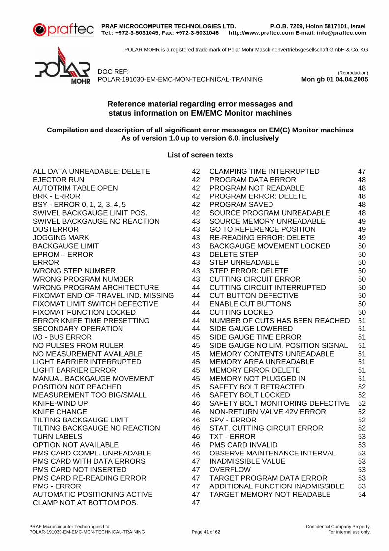
Reference material regarding error messages and status information on EM/EMC Monitor machines
Compilation and description of all significant error messages on EM(C) Monitor machines
As of version 1.0 up to version 6.0, inclusively
List of screen texts ALL DATA UNREADABLE: DELETE 42 CLAMPING TIME INTERRUPTED 47 EJECTOR RUN 42 PROGRAM DATA ERROR 48 AUTOTRIM TABLE OPEN 42 PROGRAM NOT READABLE 48 BRK - ERROR 42 PROGRAM ERROR: DELETE 48 BSY - ERROR 0, 1, 2, 3, 4, 5 42 PROGRAM SAVED 48 SWIVEL BACKGAUGE LIMIT POS. 42 SOURCE PROGRAM UNREADABLE 48 SWIVEL BACKGAUGE NO REACTION 43 SOURCE MEMORY UNREADABLE 49 DUSTERROR 43 GO TO REFERENCE POSITION 49 JOGGING MARK 43 RE-READING ERROR: DELETE 49 BACKGAUGE LIMIT 43 BACKGAUGE MOVEMENT LOCKED 50 EPROM – ERROR 43 DELETE STEP 50 ERROR 43 STEP UNREADABLE 50 WRONG STEP NUMBER 43 STEP ERROR: DELETE 50 WRONG PROGRAM NUMBER 43 CUTTING CIRCUIT ERROR 50 WRONG PROGRAM ARCHITECTURE 44 CUTTING CIRCUIT INTERRUPTED 50 FIXOMAT END-OF-TRAVEL IND. MISSING 44 CUT BUTTON DEFECTIVE 50 FIXOMAT LIMIT SWITCH DEFECTIVE 44 ENABLE CUT BUTTONS 50 FIXOMAT FUNCTION LOCKED 44 CUTTING LOCKED 50 ERROR KNIFE TIME PRESETTING 44 NUMBER OF CUTS HAS BEEN REACHED 51 SECONDARY OPERATION 44 SIDE GAUGE LOWERED 51 I/O - BUS ERROR 45 SIDE GAUGE TIME ERROR 51 NO PULSES FROM RULER 45 SIDE GAUGE NO LIM. POSITION SIGNAL 51 NO MEASUREMENT AVAILABLE 45 MEMORY CONTENTS UNREADABLE 51 LIGHT BARRIER INTERRUPTED 45 MEMORY AREA UNREADABLE 51 LIGHT BARRIER ERROR 45 MEMORY ERROR DELETE 51 MANUAL BACKGAUGE MOVEMENT 45 MEMORY NOT PLUGGED IN 51 POSITION NOT REACHED 45 SAFETY BOLT RETRACTED 52 MEASUREMENT TOO BIG/SMALL 46 SAFETY BOLT LOCKED 52 KNIFE-WIND UP 46 SAFETY BOLT MONITORING DEFECTIVE 52 KNIFE CHANGE 46 NON-RETURN VALVE 42V ERROR 52 TILTING BACKGAUGE LIMIT 46 SPV - ERROR 52 TILTING BACKGAUGE NO REACTION 46 STAT. CUTTING CIRCUIT ERROR 52 TURN LABELS 46 TXT - ERROR 53 OPTION NOT AVAILABLE 46 PMS CARD INVALID 53 PMS CARD COMPL. UNREADABLE 46 OBSERVE MAINTENANCE INTERVAL 53 PMS CARD WITH DATA ERRORS 47 INADMISSIBLE VALUE 53 PMS CARD NOT INSERTED 47 OVERFLOW 53 PMS CARD RE-READING ERROR 47 TARGET PROGRAM DATA ERROR 53 PMS - ERROR 47 ADDITIONAL FUNCTION INADMISSIBLE 53 AUTOMATIC POSITIONING ACTIVE 47 TARGET MEMORY NOT READABLE 54 CLAMP NOT AT BOTTOM POS. 47

PRAF MICROCOMPUTER TECHNOLOGIES LTD. P.O.B. 7209, Holon 5817101, Israel Tel.: +972-3-5031045, Fax: +972-3-5031046 http://www.praftec.com E-mail: [email protected]
POLAR MOHR is a registered trade mark of Polar-Mohr Maschinenvertriebsgesellschaft GmbH & Co. KG
DOC REF: (Reproduction)
POLAR-191030-EM-EMC-MON-TECHNICAL-TRAINING Mon gb 01 04.04.2005
PRAF Microcomputer Technologies Ltd. Confidential Company Property.POLAR-191030-EM-EMC-MON-TECHNICAL-TRAINING Page 42 of 62 For internal use only.
DISPLAY
CAUSE REMEDY
ALL DATA UNREADABLE
= DELETE =
Program memory area (“A“ or “B“) or PMS card no longer accessible. The data is no longer complete or is incorrect. The affected data areas can only be cleared, in order to make a new storage. Please note! This message can be displayed when the machine is switched on (put into service) and/or the first use of a PMS card, because the “A“ or “B“ memories or the PMS card have not been initialized by a deleting procedure.
Up to V4.4: Relevant memory or memory area must be cleared completely. Battery of removable memory (RSP) must be checked, Replace removable memory, PI board check PS board As of V5.0: Replace. Check voltage supply to Completely clear the relevant memory or memory area. When first using the memory area A or B - check battery of CP1 board, replace CP1 board. Check voltage supply to PS board. When using the PMS Card, check the PMS Card, its battery, PMS Card slot.
EJECTOR RUN Machine control system has initiated backgauge movement for programmed ejector run.
If there is no backgauge movement in spite of the message: check overload switches for motors, MCM unit with contactors, check voltage supply.
AUTOTRIM TABLE OPEN
AUTOTRIM table is not closed, or during closing procedure the light barrier was interrupted!
Close AUTOTRIM table Check position of S1 on SFM board, replace SFM board, check limit switch S364 and relevant cabling.
BRK - ERROR Error in data exchange between CP 1 board and control panel. Occurs on machines with V5.0 and V5.1 sporadically and without any further meaning when switched on.
Check voltage supply of PS board, Check voltage supply +9 V for KC, Check compatibility of CP1 board and KC, correct, if necessary.
BSY - ERROR 0, 1, 2, 3, 4, 5
Error which has been detected by operating system of the program on the CP1 board. Or by pressing the keyboard too hard.
Check voltage supply of PS board, verify operation, replace CP1 board replace KC.
SWIVEL BACKGAUGE
LIMIT POSITION
During manual readjustment or during the automatic limit position positioning of the swivel the relevant limit switch (depending on direction) has been reached.
Check S347 and S348 limit switches and their cabling. Check CUM.51.6/3 SER.306, SER.314 and 706 plugs. Replace DNF board, replace SER unit

PRAF MICROCOMPUTER TECHNOLOGIES LTD. P.O.B. 7209, Holon 5817101, Israel Tel.: +972-3-5031045, Fax: +972-3-5031046 http://www.praftec.com E-mail: [email protected]
POLAR MOHR is a registered trade mark of Polar-Mohr Maschinenvertriebsgesellschaft GmbH & Co. KG
DOC REF: (Reproduction)
POLAR-191030-EM-EMC-MON-TECHNICAL-TRAINING Mon gb 01 04.04.2005
PRAF Microcomputer Technologies Ltd. Confidential Company Property.POLAR-191030-EM-EMC-MON-TECHNICAL-TRAINING Page 43 of 62 For internal use only.
DISPLAY
CAUSE REMEDY
SWIVEL BACKGAUGE NO REACTION
During manual readjustment or during the automatic check positioning of the swivel backgauge, there is no true change of the backgauge position to be recognized.
Check motor for swivel backgauge (M357), potentiometer RD and rel. cabling check PM.409, SER.300, SER.301, 701, CUM.51, SER.314, SER.304 CUM.313 and 713 plugs, verify setting of DNF board, replace DNF board, replace SER unit.
DUSTERROR Data transmission error between CP1 and COMPUCUT or AUTOCUT - SPS.
Turn the machine off and then switch it on. Replace CP1 board(s), check data lines check Compubox.
JOGGING MARK With programmed additional function JOGGING MARK the operator tried to make a cut.
Check programming and operation.
BACKGAUGE LIMIT
Backgauge has moved to active table limit switch relevant for this direction. Or locking adapter with rear-table feeding, rear-table shutoff with light barrier or switch controlled rear-table guarding activated.
Check active table limit switch Replace PI board, check plug CUM.106 (and 106a, if available).
EPROM - ERROR see “TEXT - ERROR“
see “TEXT - ERROR“
ERROR Internal error message of CP1 card: ERROR1 = Error detected by OS of the CP1 operating program. ERROR2 = Text EPROM is defective or plugged incorrectly ERROR3 = Text EPROM not compatible
Turn the machine off and then switch it on. Replace CP1 board
WRONG STEP NUMBER
Invalid input of a step number under the functions STEP SELECTION & INSERT or DELETEADDITIONAL FUNCTIONS
Correct your input.
WRONG PROGRAM NUMBER
A program number < 0 > or < 98 > Change number was input.

PRAF MICROCOMPUTER TECHNOLOGIES LTD. P.O.B. 7209, Holon 5817101, Israel Tel.: +972-3-5031045, Fax: +972-3-5031046 http://www.praftec.com E-mail: [email protected]
POLAR MOHR is a registered trade mark of Polar-Mohr Maschinenvertriebsgesellschaft GmbH & Co. KG
DOC REF: (Reproduction)
POLAR-191030-EM-EMC-MON-TECHNICAL-TRAINING Mon gb 01 04.04.2005
PRAF Microcomputer Technologies Ltd. Confidential Company Property.POLAR-191030-EM-EMC-MON-TECHNICAL-TRAINING Page 44 of 62 For internal use only.
DISPLAY
CAUSE REMEDY
WRONG PROGRAM
ARCHITECTURE
Error in Eltrotact Verify program and correct architecture programming.
FIXOMAT END-OF-TRAVEL
INDICATOR MISSING
One of the two lay marks are in undefined position.
Try to go to limit position Check S341, S342, S343, S34. switches and relevant cabling Plugs CUM.307 and 707 must be checked Replace DNF board Check Fixomat motors M345 and M346.
FIXOMAT LIMIT SWITCH
DEFECTIVE
For one or both lay marks two limit position switches are simultaneously signaled as being actuated.
Check S341, S342, S343, S34. limit switches and their cabling Check plugs CUM.307 and 707, replace DNF board.
FIXOMAT FUNCTION LOCKED
Function Backgauge too close to clamp for carrying out the Fixornat function
Check switches S360, (S360q and S360b), Check CUM.106, replace PI board (S360 activated).
ERROR KNIFE - TIME PRESETTING (as of V 6.0)
This error message is shown when a cut is performed & a max. preset time of 3 Sec has been exceeded in the activated movement of the knife from TDC to BDC.
Check P2 circuit and relevant activation, verify solenoid valve Y330, replace SHM board and SK board.
SECONDARY OPERATION
This mode of operation is set automatically once the machine is turned on, if the process GO TO REFERENCE POSITION, owing to errors in the area of drive unit /LMS (or if reference position on PI board was incorrectly preset) could not be performed correctly. The “SECONDARY OPERATION“ can also be turned on in the menu “GO TOREFERENCE POSITION“ by pressing the “C“ button (in Servo data image – letter „A“).
Go to reference position Check LMS and relevant cabling, check backgauge drive unit Replace PI board.

PRAF MICROCOMPUTER TECHNOLOGIES LTD. P.O.B. 7209, Holon 5817101, Israel Tel.: +972-3-5031045, Fax: +972-3-5031046 http://www.praftec.com E-mail: [email protected]
POLAR MOHR is a registered trade mark of Polar-Mohr Maschinenvertriebsgesellschaft GmbH & Co. KG
DOC REF: (Reproduction)
POLAR-191030-EM-EMC-MON-TECHNICAL-TRAINING Mon gb 01 04.04.2005
PRAF Microcomputer Technologies Ltd. Confidential Company Property.POLAR-191030-EM-EMC-MON-TECHNICAL-TRAINING Page 45 of 62 For internal use only.
DISPLAY
CAUSE REMEDY
I/O - BUS ERROR Input and output signals of I/O – bus system cannot be read correctly.
Turn the machine off and then switch it on, verify voltage supply; if necessary, plug-in boards CP1, SK, 5FM, SHM, DNF, PDR, or CUM must be replaced.
NO PULSES FROM RULER
During motorized backgauge adjustment no pulses from linear measuring system have been recorded.
Check MC unit and contactors 11, 12 and 15, check backgauge and relevant activation, LMS and relevant cabling must be checked, replace PI board.
NO MEASUREMENT
AVAILABLE
Positioning (2 times equals key) available was initiated without indication of measurement. Or automatic advance function was activated without program measurement.
Verify operation
LIGHT BARRIER INTERRUPTED
Cut was aborted because light barrier light barrier was interrupted.
Remove all obstacles from the optical path of the light barrier and finish the cut. Check the LS board, replace, if necessary. Check light barrier, relevant cabling and setting. Check CUM.4, CUM.5, LS.600, LS.601.and LSV.602 plugs, verify voltage supply +24V, check S1 and S2 of tiltable rear-table guard. Replace SK board.
LIGHT BARRIER ERROR
Error in light barrier self testing Check setting of LS, check transmitter and receiver diodes Verify +24 V voltage supply, replace LS card
MANUAL BACKGAUGE MOVEMENT
Machine control system has movement initiated backgauge movement or backgauge motor brake was manually electrically activated.
Check switches S10, S14 and S18, check overload switch for motor, check MCM unit with contactors. Verify voltage supply.
POSITION NOT REACHED
Difference between required nominal position and actual Brake after a positioning procedure.
Check lubrication of backgauge afterrun and slow down travel must be re-determined via function “GO TO REFERENCE POSITION“. Backgauge drive unit and relevant activation must be checked, Check backgauge motor brake, if necessary clean and re-adjust it. Check LMS and relevant cabling. Replace PI board With Servo – check zero point adjustment of ESR device.

PRAF MICROCOMPUTER TECHNOLOGIES LTD. P.O.B. 7209, Holon 5817101, Israel Tel.: +972-3-5031045, Fax: +972-3-5031046 http://www.praftec.com E-mail: [email protected]
POLAR MOHR is a registered trade mark of Polar-Mohr Maschinenvertriebsgesellschaft GmbH & Co. KG
DOC REF: (Reproduction)
POLAR-191030-EM-EMC-MON-TECHNICAL-TRAINING Mon gb 01 04.04.2005
PRAF Microcomputer Technologies Ltd. Confidential Company Property.POLAR-191030-EM-EMC-MON-TECHNICAL-TRAINING Page 46 of 62 For internal use only.
DISPLAY
CAUSE REMEDY
MEASUREMENT TOO BIG/SMALL
Measurement input does not coincide with machine size
Check switch 13 Have reference pos. read in again.
KNIFE-WIND UP After switching the machine ON the knife is not in the upper resting position.
Switch the machine off and manually turn the knife back to the TDC by turning the flywheel. CAUTION! Observe safety information. Check P2 circuit, check gearbox limit switch
KNIFE CHANGE Knife change function was switched on.
Check switch S340
TILTING BACKGAUGE
LIMIT
During adjustment of tilting backgauge the direction related limit position switch has been reached.
Check limit switches S349 and S350 and relevant cabling. Verify setting of DNF board, Check plugs CUM.51, SER.304, SER.314 and 704 Replace DNF board, replace SER unit
TILTING BACKGAUGE NO
REACTION
During manual readjustment or during the automatic positioning of the tilting backgauge, no true change of the tilting backgauge position has been detected.
Check motor for tilting backgauge drive M358, check potentiometer RN & relevant cabling, Check plugs CUM.312, 712, PM.409, SER.300, SER.302, 702, CUM.51, and SER.314 Verify setting of DNF board, replace SER unit, replace DNF board.
TURN LABELS In an Eltrotact program cycle sequence it was detected that the last cut size is smaller than the minimum size to be approached.
OPTION NOT AVAILABLE
An optional function was called which either is not available or does not exist at all.
Check if corresponding function is switched on the control boards. Replace the relevant control board.
PMS CARD COMPLETLY
UNREADABLE
All the data on the PMS CARD cannot be read. Please note! This message can be displayed when a PMS CARD is used for the first time because this PMS CARD has not yet been initialized by a deleting process.
Set ON/OFF switch on PMS Card to ON. Verify if PMS Card is correctly plugged, Initialize board by a complete clearing, Verify battery voltage of PMS Card.

PRAF MICROCOMPUTER TECHNOLOGIES LTD. P.O.B. 7209, Holon 5817101, Israel Tel.: +972-3-5031045, Fax: +972-3-5031046 http://www.praftec.com E-mail: [email protected]
POLAR MOHR is a registered trade mark of Polar-Mohr Maschinenvertriebsgesellschaft GmbH & Co. KG
DOC REF: (Reproduction)
POLAR-191030-EM-EMC-MON-TECHNICAL-TRAINING Mon gb 01 04.04.2005
PRAF Microcomputer Technologies Ltd. Confidential Company Property.POLAR-191030-EM-EMC-MON-TECHNICAL-TRAINING Page 47 of 62 For internal use only.
DISPLAY
CAUSE REMEDY
PMS CARD WITH DATA ERRORS
Part of the data stored on PMS Card (individual programs and/or steps) cannot be read.
Check, if PMS Card has been correctly inserted. Delete programs or steps and enter again. Check battery voltage of PMS Card, replace PMS Card.
PMS CARD NOT INSERTED
Insert PMS Card into relevant slot on control unit.
Check, if PMS Card has been correctly inserted, replace BTM, replace KC.
PMS CARD RE-READING ERROR
Malfunction when writing on PMS Card. After check of recorded information an inequality was detected.
Check, if PMS Card has been correctly inserted. Set ON/OFF switch of PMS Card to ON. Switch any existing write protection switch on PMS Card off. Check battery voltage of PMS Card, replace PMS Card, replace BTM, replace KC.
PMS - ERROR Data transmission error between PMS Card and CP1 board. Please note! Error message “PMS - ERROR 4“ can also be issued as a sequence error of “BRK - ERROR“.
Check data line between KC and CP1. Check, if PMS Card has been correctly inserted. Set ON/OFF switch of PMS Card to ON position. Switch off any existing write protection switch on PMS Card, Check battery voltage of PMS Card, Replace PMS Card, Replace BTM, replace KC.
AUTOMATIC POSITIONING
ACTIVE
Machine control system has initiated backgauge movement.
Remedy, if there is no backgauge active movement in spite of display: Check overload switch f. motor, check MCM unit with contactors, verify voltage supply.
CLAMP NOT AT BOTTOM POSITION
Operating information in KNIFE at bottom CHANGE mode, if operator tries to cut without having lowered the clamp.
Operate cutting line indicator; if necessary, verify activation, check B29. Replace SK board
CLAMPING TIME INTERRUPTED
Between cut initiation and knife movement the cutting or clamping procedure was aborted by operator.
Verify setting of clamping time delay in BTM.

PRAF MICROCOMPUTER TECHNOLOGIES LTD. P.O.B. 7209, Holon 5817101, Israel Tel.: +972-3-5031045, Fax: +972-3-5031046 http://www.praftec.com E-mail: [email protected]
POLAR MOHR is a registered trade mark of Polar-Mohr Maschinenvertriebsgesellschaft GmbH & Co. KG
DOC REF: (Reproduction)
POLAR-191030-EM-EMC-MON-TECHNICAL-TRAINING Mon gb 01 04.04.2005
PRAF Microcomputer Technologies Ltd. Confidential Company Property.POLAR-191030-EM-EMC-MON-TECHNICAL-TRAINING Page 48 of 62 For internal use only.
DISPLAY
CAUSE REMEDY
PROGRAM DATA ERROR
PROGRAM NOT READABLE PROGRAM
ERROR: DELETE
All the data in a program in the memory areas of the machine („A“ or „B“) or a program of the PMS card cannot be read.
Remedy up to V4.4: Completely delete the relevant program and input again. Check battery of removable memory (RSP), Program error Replace removable memory, replace PI board. Check voltage supply to PS board, replace PS board. Remedy as of V5.0: Completely delete the relevant program and input again. When using the A or B memory area, check CP1 board and battery. Check voltage supply of PS board, replace PS board. When using the PMS Card, check the PMS Card, its battery, PMS-Card slot, replace BTM, replace KC.
PROGRAM SAVED
Someone attempted to change the program or delete a protected program.
Un-protect program under “Program Information“
SOURCE PROGRAM
UNREADABLE
While using the functions “COPY PROGRAMS“, “COPY ONTO PMS CARD“ and “LOAD FROM PMS CARD“ data of the source program could be read.
Remedy up to V4.4: Delete relevant program completely and re-input. Check battery of removable memory, replace removable memory replace PI board, Check voltage supply of PS board, replace PS board. Remedy as of V5.0: Completely delete the relevant program and input again. Use of memory area A or B –Check battery of CP1 board, replace CP1 board, Verify voltage supply to PS board, replace PS board. When using the PMS - Card, verify the PMS Card, its battery, the PMS Card slot, replace BTM, replace KC.
SOURCE MEMORY
UNREADABLE V4.4
While using the functions “COPY PROGRAMS“, “COPY ONTO PMS CARD“ and “LOAD FROM PMS CARD“ the source memory cannot be read.
Remedy up to V4.4: Clear the relevant memory or memory area completely. Check battery of removable memory, Replace removable memory, replace PI board, check voltage supply of PS board, replace PS board.

PRAF MICROCOMPUTER TECHNOLOGIES LTD. P.O.B. 7209, Holon 5817101, Israel Tel.: +972-3-5031045, Fax: +972-3-5031046 http://www.praftec.com E-mail: [email protected]
POLAR MOHR is a registered trade mark of Polar-Mohr Maschinenvertriebsgesellschaft GmbH & Co. KG
DOC REF: (Reproduction)
POLAR-191030-EM-EMC-MON-TECHNICAL-TRAINING Mon gb 01 04.04.2005
PRAF Microcomputer Technologies Ltd. Confidential Company Property.POLAR-191030-EM-EMC-MON-TECHNICAL-TRAINING Page 49 of 62 For internal use only.
DISPLAY
CAUSE REMEDY
SOURCE MEMORY
UNREADABLE V5.0
While using the functions “COPY PROGRAMS“, “COPY ONTO PMS CARD“ and “LOAD FROM PMS CARD“ the source memory cannot be read.
Remedy up to V5.0: Relevant memory or and memory area must be cleared completely. Use of memory area A or B - Check battery of CP1 board, replace CP1 board. Power supply check PS board, replace PS. When using the PMS Card, check the PMS Card, its battery, PMS Card slot, replace BTM, replace KC.
GO TO REFERENCE
POSITION
When machine is switched on the parameters required for normal operation, such as the latest backgauge position, last brake afterrun value, length of slow down travel etc. are not available. This message is output when: The machine had been switched off during activated backgauge movement. A machine is switched on for the first time, (commissioning). The CP1 board had been replaced. Function has been selected in PRESET FUNCTION menu. If this status occurs without any of the above mentioned conditions the saving of data might be disturbed when the machine is switched off.
Check battery on CP1 board, Replace CP1 board, check switches S10, S14 and S18. Check keys in BTM for activating the backgauge movement.
RE-READING ERROR: DELETE
Malfunction when writing on machine program memory (“A“ or “B“) or onto PMS Card. When checking the written information a discrepancy was detected.
Check battery of CP1 board, replace CP1 board. Check, if PMS CARD has been correctly inserted. Set ON/OFF switch of PMS Card to ON position, Any existing write protection switch on PMS Card must be turned off, Verify battery voltage of PMS Card, replace PMS Card, replace BTM, replace KC.

PRAF MICROCOMPUTER TECHNOLOGIES LTD. P.O.B. 7209, Holon 5817101, Israel Tel.: +972-3-5031045, Fax: +972-3-5031046 http://www.praftec.com E-mail: [email protected]
POLAR MOHR is a registered trade mark of Polar-Mohr Maschinenvertriebsgesellschaft GmbH & Co. KG
DOC REF: (Reproduction)
POLAR-191030-EM-EMC-MON-TECHNICAL-TRAINING Mon gb 01 04.04.2005
PRAF Microcomputer Technologies Ltd. Confidential Company Property.POLAR-191030-EM-EMC-MON-TECHNICAL-TRAINING Page 50 of 62 For internal use only.
DISPLAY
CAUSE REMEDY
BACKGAUGE MOVEMENT
LOCKED
Via SFM board the backgauge movement was locked.
Locking during rear-table loading Check rear-table protection with LS or switch controlled rear-table guarding. On machines with SERVO: check backgauge drive and relevant activation, LMS and relevant cabling, replace PI board.
DELETE STEP STEP
UNREADABLE STEP ERROR:
DELETE
In a program of the machine memories “A“ or “B“ the data of one or more steps are no longer readable. The relevant steps are marked in the menus “CUTTING PROGRAM“ and “PROGRAM INFORMATION“ by representing their contents with lines “-—“.
Delete steps and store again, re-input the entire program, if necessary. Check battery of CP1 board, Replace CP1 board. Check battery of removable memory, replace removable memory, replace PI board.
CUTTING CIRCUIT ERROR
SK board detects error in cutting circuit cycle.
Check cutting circuit (LED’s) replace SK board.
CUTTING CIRCUIT INTERRUPTED
No agreement between software - activation and safety control channel of SK board. Sporadic occurrence of this message does not indicate a malfunction in any case.
Check if knife is in TDC, if necessary, wind the knife up. Turn machine off and turn the knife manually to its top dead center by turning the flywheel. PLEASE NOTE! Observe safety information. Check gearbox limit switches. Check magnet Y.SB, replace SK board.
CUT BUTTON DEFECTIVE
For one or both cut buttons the input signals for make and break contacts are simultaneously recognized as being activated.
Check cut button and replace, if necessary (see IP1/91 section 2.20.00e) Check CUM.15 plug Replace SK board.
ENABLE CUT BUTTONS
Indicates that at least one cut button is pressed.
Check cut button and replace, if necessary (see IP1/91 section 2.20.00e), Check plug CUM.15, Replace SK board (Rel. K4 fr. HMY)
CUTTING LOCKED
Attempted execution of cut with activated signal “cut is blocked“ of SFM board.
Check Autotrim function and waste removal stroke, check backgauge movement, Replace SFM board. Replace PI board.

PRAF MICROCOMPUTER TECHNOLOGIES LTD. P.O.B. 7209, Holon 5817101, Israel Tel.: +972-3-5031045, Fax: +972-3-5031046 http://www.praftec.com E-mail: [email protected]
POLAR MOHR is a registered trade mark of Polar-Mohr Maschinenvertriebsgesellschaft GmbH & Co. KG
DOC REF: (Reproduction)
POLAR-191030-EM-EMC-MON-TECHNICAL-TRAINING Mon gb 01 04.04.2005
PRAF Microcomputer Technologies Ltd. Confidential Company Property.POLAR-191030-EM-EMC-MON-TECHNICAL-TRAINING Page 51 of 62 For internal use only.
DISPLAY
CAUSE REMEDY
NUMBER OF CUTS HAS BEEN
REACHED
Cut counter has reached preset value.
Cut counter preselection in survey (8) must be readjusted or switched off.
SIDE GAUGE LOWERED
Attempted cut with activated signal “side gauge lowered“ SHM board. Automatic knife is switched off or set back to the step “prepared“.
Move side gauge up, Replace SHM board.
SIDE GAUGE TIME ERROR
Side gauge limit position is not reached within admissible time.
Check side gauge limit switch Check side gauge for mechanical stiffness, replace SHM board, check locking of rear table loading.
SIDE GAUGE NO LIMIT
POSITION SIGNAL
When machine is switched on at least one side gauge is in undefined position.
Move side gauge up or down. Check side gauge limit switch, Check switch positions on SHM board, replace SHM board, check locking of rear table loading.
MEMORY CONTENTS
UNREADABLE MEMORY AREA UNREADABLE
MEMORY ERROR DELETE
None of the data in a memory area of the machine (“A“ or “B“) or in a memory area of the PMS card can be read. Please note! This message may be shown (put into service) and/or on first use of a PMS card because the “A“ or “B“ memories or the PMS card has not been initialized by a deleting procedure.
Remedy up to V4.4: Relevant memory or memory area must be cleared completely. Check battery of removable memory, replace removable memory, if necessary, PI board. Check voltage supply of PS board, replace PS board. Remedy as of V5.0: Relevant memory or memory area must be cleared completely. When memory area A or B are used. Check battery of CP1 board, replace CP1 board. Check power supply to PS board, replace PS board. When using the PMS Card, check the PMS Card, its battery, PMS Card slot. Replace BTM and KC, if necessary.
MEMORY NOT PLUGGED IN
On versions up to V4.3 or older selected removable memory is not plugged onto the PI board.
Plug the removable memory into “A“ or “B“ slot on PI board. Replace removable memory, replace PI board.

PRAF MICROCOMPUTER TECHNOLOGIES LTD. P.O.B. 7209, Holon 5817101, Israel Tel.: +972-3-5031045, Fax: +972-3-5031046 http://www.praftec.com E-mail: [email protected]
POLAR MOHR is a registered trade mark of Polar-Mohr Maschinenvertriebsgesellschaft GmbH & Co. KG
DOC REF: (Reproduction)
POLAR-191030-EM-EMC-MON-TECHNICAL-TRAINING Mon gb 01 04.04.2005
PRAF Microcomputer Technologies Ltd. Confidential Company Property.POLAR-191030-EM-EMC-MON-TECHNICAL-TRAINING Page 52 of 62 For internal use only.
DISPLAY
CAUSE REMEDY
MECHANICAL LOCK UNLOCKED
This message indicates that home position of machine (knife in top dead center or machine just turned on) the mechanical lock (or the safety rocker switch) for the knife bar is not in the safety position.
Check if knife is in TDC, wind the knife up, if necessary. Turn machine off and turn the knife manually to its top dead center by turning the flywheel. PLEASE NOTE! Observe safety information. Check smooth operation of mechanical lock or safety rocker switch). Check magnet Y.SB, check switch B.SBE, Check plugs 44 and CUM.9 , replace SK board. (Rel. K3 of MHY)
MECHANICAL LOCK LOCKED
Before the cut is started the mechanical lock (or safety rocker switch) does not reach proximity switch B.SBA or not in a timely manner, or leaves the B.SBA proximity switch during the cutting procedure.
Check smooth operation of mechanical lock or safety rocker switch). Check magnet Y.SB, check switch B. SBA, Check plugs 44 and CUM. Replace SK board.
MECHANICAL LOCK
MONITORING DEFECTIVE
The mechanical lock (or safety rocker switch) is in an undefined state of malfunction. Both proximity switches B.SBE and B.SBA signalize simultaneously the positions “knife bar released“ and “knife bar locked“.
Check smooth operation of mechanical lock (or safety rocker switch). Check magnet Y.SB, check switches B.SBE and B.SBA. Check plugs 44 and CUM 9, Replace SK board.
NON-RETURN VALVE 42V
ERROR
On one activated non-return valve Y315 no voltage of +42 V is supplied to switching line of non-return valve.
Verify voltage supply (measuring point SK.P1 Nom. +50 V to +55 V) solenoid valve 315 (ohms) must be checked, plug CUM.6 and magnet. Replace SK board.
SPV - ERROR Internal error message for memory management of CP1 board.
Switch machine off and on Verify voltage supply, Replace CP1 board.
STATIC CUTTING CIRCUIT ERROR
No agreement between software activation and safety control channel of SK board. Verify voltage supply, Sporadic occurrence of this message does not necessarily indicate a malfunction in any case. On V5.1 and V4.2 this message occurs if an interrupted cut is continued while the light barrier is interrupted.
Remove any obstacles from the optical path of the LS and finish the cutting process. Replace SK board.

PRAF MICROCOMPUTER TECHNOLOGIES LTD. P.O.B. 7209, Holon 5817101, Israel Tel.: +972-3-5031045, Fax: +972-3-5031046 http://www.praftec.com E-mail: [email protected]
POLAR MOHR is a registered trade mark of Polar-Mohr Maschinenvertriebsgesellschaft GmbH & Co. KG
DOC REF: (Reproduction)
POLAR-191030-EM-EMC-MON-TECHNICAL-TRAINING Mon gb 01 04.04.2005
PRAF Microcomputer Technologies Ltd. Confidential Company Property.POLAR-191030-EM-EMC-MON-TECHNICAL-TRAINING Page 53 of 62 For internal use only.
DISPLAY
CAUSE REMEDY
TXT - ERROR After turning the machine on erroneous identification of text EPROM on CP1 board.
Replace CP 1 board.
PMS - CARD INVALID
The PMS card plugged into the control unit cannot be identified.
Use original PMS Card. Check, if PMS Card has been inserted correctly, replace PMS Card.
OBSERVE MAINTENANCE
INTERVAL
Counter for service has exceeded interval 100,000.
Reset the counter for service under survey of functions (7).
INADMISSIBLE VALUE
During the programming an inadmissible input was detected (e.g. total cuts - 0).
Verify programming.
OVERFLOW When using the calculating function, an overflow of the arithmetic memory was caused.
TARGET PROGRAM DATA
ERROR
While using the functions “COPY PROGRAMS“, “COPY ONTO PMS CARD“ and „LOAD FROM PMS CARD“ all the data from the target program could not be read.
Remedy up to V4.4: Completely delete the relevant program and input again, check battery of removable memory, replace removable memory, replace PI board, check voltage supply of PS board, replace PS board. Remedy as of V5.0: Completely delete the relevant program and input again. When using the memory areas A or B - check battery of CP1 board, replace CP1 board. Check voltage supply to PS board, replace PS board. When using the PMS Card, check the PMS Card, its battery, PMS Card slot, replace BTM, replace KC.
ADDITIONAL FUNCTION
INADMISSIBLE
Inadmissible additional function was called up.
Verify operation.

PRAF MICROCOMPUTER TECHNOLOGIES LTD. P.O.B. 7209, Holon 5817101, Israel Tel.: +972-3-5031045, Fax: +972-3-5031046 http://www.praftec.com E-mail: [email protected]
POLAR MOHR is a registered trade mark of Polar-Mohr Maschinenvertriebsgesellschaft GmbH & Co. KG
DOC REF: (Reproduction)
POLAR-191030-EM-EMC-MON-TECHNICAL-TRAINING Mon gb 01 04.04.2005
PRAF Microcomputer Technologies Ltd. Confidential Company Property.POLAR-191030-EM-EMC-MON-TECHNICAL-TRAINING Page 54 of 62 For internal use only.
DISPLAY
CAUSE REMEDY
TARGET MEMORY NOT
READABLE
While using the functions “COPY PROGRAMS“, “COPY ONTO PMS CARD“ and „LOAD FROM PMS CARD“ no data of the target memory can be read.
Remedy up to V4.4: Completely delete the relevant program and input again. Check battery of removable memory, replace removable memory, replace P1 board, Check voltage supply of PS board, replace PS board. Remedy as of V5.0: Clear the relevant program completely and input again. When using the A or B memory area – check battery of CP1 board, replace CP1 board. Verify voltage supply to PS board. When using the PMS Card, check the PMS Card, its battery, check the PMS Card slot, replace BTM, replace KC.

PRAF MICROCOMPUTER TECHNOLOGIES LTD. P.O.B. 7209, Holon 5817101, Israel Tel.: +972-3-5031045, Fax: +972-3-5031046 http://www.praftec.com E-mail: [email protected]
POLAR MOHR is a registered trade mark of Polar-Mohr Maschinenvertriebsgesellschaft GmbH & Co. KG
DOC REF: (Reproduction)
POLAR-191030-EM-EMC-MON-TECHNICAL-TRAINING Mon gb 01 04.04.2005
PRAF Microcomputer Technologies Ltd. Confidential Company Property.POLAR-191030-EM-EMC-MON-TECHNICAL-TRAINING Page 55 of 62 For internal use only.
SERVICE INFORMATION
Since the I/O bus boards are switched in parallel (see block diagram, page 3) a defective board may affect machine functions, which are controlled by another board. By removing the boards one by one the defective board can be localized.
1. All machine functions except for the monitor display are possible without the Video (VID) plug-inboard.
2. The functions of backgauge movement, display and control panel are possible without the
cuttingcircuit (SK) board plugged in. The message “enable cut buttons“ is displayed on the screen.
3. All the machine function except for the operating elements on the control panel are possible without the assembly of Keyboard Computer (KC) and control unit (BTM)
4. Self-test of the Keyboard Computer (KC) and control unit (BTM) assembly: With the machine
switched off, remove the plug-in connection of the X500 serial interface from the KC board. (see drawing on page 26)
Make a short-circuit bridge by plugging the test connector onto X500.
The test plug is on the right side of plug X500. Switch the machine on. Activate self-test by pressing the key S1 on the KC board. The red LED “Test okay“ V20 is lit when the self-test of the Keyboard Computer has been performed without errors. When one of the keys is actuated or released or when the rotary switch is adjusted on board BTM you hear an acoustic signal. While a key is being actuated the LED V20 „Test okay“ is out. Turn the machine off and re-establish the X500 connection. Put test plug back to the position of rest. The test plug does not affect the machine control system.
5. When the machine is switched off with the backgauge brake electrically activated or the last
backgauge position stored no longer available, for instance because the battery on the CP1 boardhas been replaced, the machine has to be moved to reference position after it has been switched on. Once the control voltage has been connected the monitor displays the prompt = go to reference position = actuate hand wheel.

PRAF MICROCOMPUTER TECHNOLOGIES LTD. P.O.B. 7209, Holon 5817101, Israel Tel.: +972-3-5031045, Fax: +972-3-5031046 http://www.praftec.com E-mail: [email protected]
POLAR MOHR is a registered trade mark of Polar-Mohr Maschinenvertriebsgesellschaft GmbH & Co. KG
DOC REF: (Reproduction)
POLAR-191030-EM-EMC-MON-TECHNICAL-TRAINING Mon gb 01 04.04.2005
PRAF Microcomputer Technologies Ltd. Confidential Company Property.POLAR-191030-EM-EMC-MON-TECHNICAL-TRAINING Page 56 of 62 For internal use only.
When searching the reference position the control system determines the following parameters:
End of table (Distance between cutting line and rake when the rear table limit switch is
reached).
Slow down travel (Distance between the switchover point from the high to the low backgauge motor speed on one hand and reaching the low speed on the other hand). The computer multiplies this distance by the factor of 1.5 in order to compensate for fluctuations.
Brake afterrun (Distance between the shut-off point of the brake lifting solenoid and the backgauge at standstill).
Caution! If the backgauge movement has been modified, for instance by
- replacement or readjustment of the brake lifting solenoid - replacement of the backgauge motor
- modification of the reference position
- replacement or readjustment of the spindle nuts
- readjustment of sledge guide
- change of position of the rear table limit switch
- replacement of the CP1 board,
the control system has to determine these parameters again while the machine is switched off with the brake electrically activated. When the machine is turned on for searching the reference position, activate the advance or return stroke.
6. The front and rear limit stops of the backgauge movement is exclusively determined by the
positions of the table limit switches (hardware shutoff). Adjust the limit switch in such a way that the smallest attainable cut size of the 92, 115 and 137machines is 25 mm, and on the 155 and 176 machines 35 mm.
The remaining limit switches must be set to ensure that the backgauge motor is switched off at least 10 mm before the mechanical stop at the false clamp plate or at the end of the table is reached.
7. When the “Service“ function has been selected from the Survey of functions, enter the code number
8520 and confirm with the “actual position” key.
The screen displays: (as of program version V2.0)
(1) Machine data (2) Change machine data

PRAF MICROCOMPUTER TECHNOLOGIES LTD. P.O.B. 7209, Holon 5817101, Israel Tel.: +972-3-5031045, Fax: +972-3-5031046 http://www.praftec.com E-mail: [email protected]
POLAR MOHR is a registered trade mark of Polar-Mohr Maschinenvertriebsgesellschaft GmbH & Co. KG
DOC REF: (Reproduction)
POLAR-191030-EM-EMC-MON-TECHNICAL-TRAINING Mon gb 01 04.04.2005
PRAF Microcomputer Technologies Ltd. Confidential Company Property.POLAR-191030-EM-EMC-MON-TECHNICAL-TRAINING Page 57 of 62 For internal use only.
By input of the relevant number one of the two sub-menus is branched.
(1) Machine data EM(C) - Monitor V... Language presetting E.g.: German Measuring unit presetting E.g.: cm Text - EPROM Version Software Version V... Brake afterrun E.g.: 0.034 cm Slow down travel E.g.: 2.154 cm End of table E.g.: 116.83 cm (2) Change machine data EM(C) - Monitor V... (1) Accuracy allowance (max. permissible tolerance in a positioning
procedure. The factory setting is 0.008 cm. Possible values: 0.008 – 0.1 cm)
(2) Total cut counter E.g.: 88888888
(3) Switch-off display correction (if the max. admissible tolerance is not exceeded in a positioning process the actual position display will be rounded up or down.)
(3a) Switch-on display correction (In this case the “actual position“ display is not rounded.)
(4) Print service report
(5) Input/output control (shows the conditions of all essential input and output signals of the control system. Those signals which are not in their ground level state are inverted. The features “clamping“, “cut“, “mechanical cutting-line indicator“ and “manual backgauge movement“ are available.)
(6) Set reference position (indication to support the setting of the reference position)
(7) Remark 8. The functioning of the VID board and the screen can be verified by turning on the control voltage
without the CP1 board installed in the machine. The screen shows a test pattern which consists of horizontal and vertical lines. This test pattern can be used for setting the image orientation, height, width and linearity. The controllers for adjusting these parameters are located on the PC Board inside the screen housing. Please learn the positions of the controls from an adhesive label on the tube bulb.

PRAF MICROCOMPUTER TECHNOLOGIES LTD. P.O.B. 7209, Holon 5817101, Israel Tel.: +972-3-5031045, Fax: +972-3-5031046 http://www.praftec.com E-mail: [email protected]
POLAR MOHR is a registered trade mark of Polar-Mohr Maschinenvertriebsgesellschaft GmbH & Co. KG
DOC REF: (Reproduction)
POLAR-191030-EM-EMC-MON-TECHNICAL-TRAINING Mon gb 01 04.04.2005
PRAF Microcomputer Technologies Ltd. Confidential Company Property.POLAR-191030-EM-EMC-MON-TECHNICAL-TRAINING Page 58 of 62 For internal use only.
9. In order to retain the data when the control system is switched off the interchangeable memory and
the CP1 board are provided with (3.5 V) batteries. These batteries should be replaced every five years or when the battery voltage falls below 3 Volts.
The battery of the interchangeable memory should be changed with the memory plugged in and the control voltage switched on, because the stored program data will otherwise be lost. It is also possible to copy the program data into another memory before replacing the battery. The CLK board also carries a battery (2.4 V), which supplies the timer module when the machine is switched off.
Secondary operation The secondary operation makes the manual backgauge movement as well as the clamping and cutting functions possible. The monitor continues to display all the data except for the “actual position“. Via the keys on the control unit the individual menus can be selected (also the “Service“ function).
There are two ways to get to the secondary operation 1. When searching the reference position and no reference point is detected because of a defective
measuring system, a defective connecting cable for the measuring system or a defective PI plug-in board, the system will automatically switch to secondary operation after the third attempt. The “program data“ image is shown, and instead of the “actual position“ the text “secondary operation“ is displayed.
2. If the “Program Data“ button is pressed before or after searching the reference position, the system
switches instantly over to secondary operation. Please note! When the optional equipment “optimized high-speed backgauge“ is available the backgauge movement may be locked when the measuring system has suffered a failure. In this case, no search of the reference position is possible. In this case, press the “program data“ key to start the secondary operation.
Deactivating automatic knife functions (see IP1/97)
POLAR EM/EMC - Monitor machines 1. Plug the jumper (MS) onto the cutting circuit board (SK). 2. Install board SFM unless it is already installed. 3. Insert a jumper on the CU, from plug 57, pin 5 to pin 9. 4. Separate the strip conductor for the „automatic knife ON“ key from the control unit. Please remember to note down the changes on the customer’s circuit diagram

PRAF MICROCOMPUTER TECHNOLOGIES LTD. P.O.B. 7209, Holon 5817101, Israel Tel.: +972-3-5031045, Fax: +972-3-5031046 http://www.praftec.com E-mail: [email protected]
POLAR MOHR is a registered trade mark of Polar-Mohr Maschinenvertriebsgesellschaft GmbH & Co. KG
DOC REF: (Reproduction)
POLAR-191030-EM-EMC-MON-TECHNICAL-TRAINING Mon gb 01 04.04.2005
PRAF Microcomputer Technologies Ltd. Confidential Company Property.POLAR-191030-EM-EMC-MON-TECHNICAL-TRAINING Page 59 of 62 For internal use only.
Printer interface
All Monitor machines are prepared for connecting a printer. This connection is made by a serialinterface on the front side of the CP1 (X5) board. Polar Machines are designed to work with Epson printers equipped with serial interfaces.Thenecessary connecting cable is included in the toolbox of every Monitor machine upon delivery. The following list shows the required devices:
Epson Matrix printer, such as: FX - 870 Purchase no. C094011 Serial interface: Purchase no. 8143 Pull/push tractor Purchase no. C806382 Sheet feeder Purchase no. C800202 The above listed components can be purchased from Epson. Printer cable id. No. 020328 (Polar)
The Epson printers must be adjusted for program versions V1.0, V1.1, V2.0, V3.1(S), V4.0(S) and V4.1(S), respectively, in the following way:
Installation at EPSON FX800 printer
1. Printer Board: Switch position (DIP - Switch)
DIP-Switch SW: 1 = PIN 1 = OFF DIP-Switch SW: 2 = PIN 1 = OFF 1 = PIN 2 = OFF 2 = PIN 2 = ON 1 = PIN 3 = ON 2 = PIN 3 = ON 1 = PIN 4 = OFF 2 = PIN 4 = ON 1 = PIN 5 = ON 1 = PIN 6 = ON 1 = PIN 7 = ON 1 = PIN 8 = ON
Please remember to note down the changes on the customer’s circuit diagram

PRAF MICROCOMPUTER TECHNOLOGIES LTD. P.O.B. 7209, Holon 5817101, Israel Tel.: +972-3-5031045, Fax: +972-3-5031046 http://www.praftec.com E-mail: [email protected]
POLAR MOHR is a registered trade mark of Polar-Mohr Maschinenvertriebsgesellschaft GmbH & Co. KG
DOC REF: (Reproduction)
POLAR-191030-EM-EMC-MON-TECHNICAL-TRAINING Mon gb 01 04.04.2005
PRAF Microcomputer Technologies Ltd. Confidential Company Property.POLAR-191030-EM-EMC-MON-TECHNICAL-TRAINING Page 60 of 62 For internal use only.
2. Serial - Interface Board: switch positions
DIP - Switch SW: 1 = PIN1 = OFF Program Version V2.0.0, V3.1.0(S) Program Version V4.0(S), V4.1(S) 1 = PIN1 = ON Program Version V1.1/V1.0 1 = PIN2 = ON 1 = PIN3 = ON 1 = PIN4 = ON 1 = PIN5 = ON 1 = PIN6 = OFF 1 = PIN7 = OFF 1 = PIN8 = OFF
DIP - Switch SW: 2 = PIN1 = ON 2 = PIN2 = ON 2 = PIN3 = OFF 2 = PIN4 = OFF 2 = PIN5 = OFF 2 = PIN6 = OFF
3. Serial - Interface Board: Set jumpers
Jumper: 1 = OFF 2 = OFF 3 = OFF 4 = OFF 5 = ON 6 = OFF 8A = ON 8B = OFF X = ON F = OFF CL = ON RS = OFF

PRAF MICROCOMPUTER TECHNOLOGIES LTD. P.O.B. 7209, Holon 5817101, Israel Tel.: +972-3-5031045, Fax: +972-3-5031046 http://www.praftec.com E-mail: [email protected]
POLAR MOHR is a registered trade mark of Polar-Mohr Maschinenvertriebsgesellschaft GmbH & Co. KG
DOC REF: (Reproduction)
POLAR-191030-EM-EMC-MON-TECHNICAL-TRAINING Mon gb 01 04.04.2005
PRAF Microcomputer Technologies Ltd. Confidential Company Property.POLAR-191030-EM-EMC-MON-TECHNICAL-TRAINING Page 61 of 62 For internal use only.
Change of software versions according to IP
CP1 IP EMC EM SERVO
CP1 V1.1 020150 CP1 V2.0 T08 ab 86 IP4/86 020152 020930 CP1 V3.1 T08 ab 88 IP4/87 023888 023892 023890
From V4.0 with Graphics and with VID 3.0, 020622 CP1 V4.0 T08 ab 88 IP2/89 023590 023802 023804 CP1 V4.1 T08 ab 89 IP2/89 023501 023771 023611
From V4.0 with PMS Board and KC V2.1, 020830 CP1 V5.0 T08 ab 90 IP1/90 024330 024350 024340 CP1 V5.1 T08 ab 90 IP2/90 024331 024351 024341
V4.2 with operation like V5.0 but without PMS Board Replaced V4.0 and V4.1
CP1 V4.2 T08 ab 90 IP2/90 023592 023772 023612 From V6.0 with Menu Display and KC V2.2, 020832
CP1 V6.0 T11 ab 91 IP2/91 024840 024860 024850 V4.3 with operation like V6.0 but without PMS Board
Replaced V4.0 to V4.2 CP1 V4.3 T11 ab 94 IP1/94 024841 024841 Like EMC
V4.4 with operation like V6.2 but without PMS Board Replaced V4.0 to V4.3
CP1 V4.4 T12A ab 94 IP1/94 023594 023774 Like EMC

PRAF MICROCOMPUTER TECHNOLOGIES LTD. P.O.B. 7209, Holon 5817101, Israel Tel.: +972-3-5031045, Fax: +972-3-5031046 http://www.praftec.com E-mail: [email protected]
POLAR MOHR is a registered trade mark of Polar-Mohr Maschinenvertriebsgesellschaft GmbH & Co. KG
DOC REF: (Reproduction)
POLAR-191030-EM-EMC-MON-TECHNICAL-TRAINING Mon gb 01 04.04.2005
PRAF Microcomputer Technologies Ltd. Confidential Company Property.POLAR-191030-EM-EMC-MON-TECHNICAL-TRAINING Page 62 of 62 For internal use only.
Compatibility of the Video – CP1 and KC boards
Video
V1.0 020131
V2.0 020132
V3.0 020620
V3.0 020621
V3.0 020622
CP1 1* 3* 1* 3* 1* 3* 2* 4* 2* 4* 5* KC V1.1 x x 185 V2.0 x x 185 V3.1 x x 185 V4.0 From V4.0 with Graphics x 185 V4.1 x 185 V5.0 From V5.0 with PMS Board x V2.1 V5.1 x V2.1 V4.2 Like V5.0 but without PMS Board x 185 V6.0 From V6.0 with Menu Display x V2.2 V4.3 Like V6.0 but without PMS Board x 185 V6.2 Knife Circuit Time/Error Memory x V2.2 V4.4 x 185
Explanation of Video Cards
1* = Half Size, 2 * = Double Size, 3* = Monochrome, 4* = Mono Color, 5* = Graphics CP1 V4.2 Replaces V4.0 to V4.1
Same software as V5.0, but meant for machines without PMS Card CP1 V4.3 Replaces V4.0 to V4.2
Same software as V6.0, but meant for machines without PMS Card CP1 V 4.4 Replaces V4.0 to V4.3
Same software as V6.2, but meant for machines without PMS Card