technical training for smms i selection tool - toshiba 2011/02 vrf - commercial/04 link 4... ·...
TRANSCRIPT

1
EMEA Training 2010 Presentation Reference TP10-Vi04-01
SMMS–i Selection Tool
Technical Training For...
SMMS-i Selection Tool Overview
• Two methods of System Design
– Wizard Based Selection
– Drag-&-Drop Based Selection
• Built-in Checking of the System
• Selection Tool Outputs
– Equipment, System, Indoor & Outdoor Lists
– Controls Network
– Wiring Schematic
– Piping Schematic
2

1. System Design Method Selection
2. Project Input and Editing
3. Outdoor Design Temperature Setting
4. Indoor Unit Selection
5. Outdoor unit Selection and System Assignment
6. System Information & Layout Editing
7. Control Device Selection
8. System Check
9. Outputs
10. Drag-n-Drop Method Overview
Contents
3

1. System Design Method Selection
• Start the software and the following welcome screen will
be shown
4

1. System Design Method Selection
• Select which design method you want to use:
• In this case select the Wizard Method
5

2. Project Input & Editing
• Select either the New Project Icon or the Edit Project Icon
New Project
Edit Project
Project Copy
Exit
Next Step Previous Step
6

New Project 2. Project Input & Editing
• Fill in the required project information
7

• Select the design temperature setting for both Heating and
Cooling modes
Cooling Dry Bulb temperature
Heating Wet Bulb Temperature
3. Outdoor Design Temperature Setting
8

Click Create Indoor Unit button
4. Indoor Unit Selection
9
• Select the Create Indoor Unit button

Click Edit Indoor Unit button
4. Indoor Unit Selection
10
• Select Edit Indoor Unit button, if you need to make changes

1. Select Indoor Unit (model type)
2. Input Indoor Unit name
Room name
Floor name
3. Select Capacity selection
method ~ Auto or Manual
4. Input Indoor group data
5. Input Indoor unit design
temperature data
11
4. Indoor Unit Selection • Complete the required data
in the form as shown:

12
4. Indoor Unit Selection
1. Enter the Capacity requirements
2. Enter the Equivalent &/or
Actual pipe lengths
3. Select which local remotes
you want to use
4. Select which fan speed your
design requires
5. Shortcut links for related
manuals
• Complete the required data
in the form as shown:

13
4. Indoor Unit Selection
• Select Settings from the Tool Menu
• You can then customise the Main
Window display parameters

14 14
4. Indoor Unit Selection
• Select the Specification Check Tab
• You can choose which System
Design Checks are applied

15
4. Indoor Unit Selection
• Select the Output/Print Tab
• You can select which items are
included on the output documents

4. Indoor Unit Selection
• Select the Drawing Frame Tab
• You can specify the details that can
be printed on the drawing frame

17
4. Indoor Unit Selection • Input all the Indoor Units on the site, to make a complete list

18
4. Indoor Unit Selection • You can use the copy function to copy the selected Indoor
Unit
Click Copy Indoor Unit button

19
4. Indoor Unit Selection • You can use the multiple copy function to copy the selected
Indoor Unit as many times as you select
Click Multi Copy Indoor Unit button

Click New Outdoor unit Input button
20
5. Outdoor Unit Selection and System Assigning • Press the Create Outdoor Unit button

Refrigerant Cycle Number
Refrigerant Cycle Name
System Type
Capacity Selection
21
5. Outdoor Unit Selection and System Assigning
• Complete the required data in the form as shown:
System diversity selection
Wiring System Name
Outdoor Unit Position
Main Pipe Length

22
5. Outdoor Unit Selection and System Assigning
• Select the CDU
which you want
to add units to
• Using the Add
and Remove
buttons, select
the Indoor Units
which are to be
assigned to the
Outdoor Units /
system

23
5. Outdoor Unit Selection and System Assigning
• Repeat for all
Refrigerant
systems until all
Indoor units are
assigned

24
6. System Information & Layout Editing
• Edit each system layout to match the Design Requirements

25
7. Control Device Selection
• Add any Central Control device or BMS Gateway or
Controller

26
8. System Check
• Displays the
results of the
System Check
for all Systems
• The Summary
table at the top
displays the
overall result
• Select the
system you want
to review and
the detailed test
results are
shown below

27
8. System Check
• Whichever refrigerant
system has been
selected at the top, the
details can be seen in
the table below
• If you scroll down in the
detailed result table,
you can see each
check and the result for
that check
• From here you can
identify any issues that
have been found
28
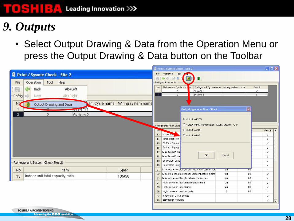
9. Outputs
• Select Output Drawing & Data from the Operation Menu or
press the Output Drawing & Data button on the Toolbar

29
9. Outputs
• Select whichever Output is required
• In this case the option that produces all possible Outputs has
been selected
• It is also possible to just select one individual type of output if
required

30
9. Output ~ Total Equipment List
• The Excel spreadsheet that it created contains several Tabs,
the first Tab contains the complete list of all the equipment
used on the selected project.

Name
Capacity rank
Quantity
Additional
Refrigerant
Pipe length
31
9. Output ~ System List
• The System List Tab lists all the Refrigerant Systems and the
specific details of each system

32
9. Output ~ Indoor Unit List
• The Indoor Unit List Tab lists all the Indoor Units and the specific
details of each unit

33
9. Output ~ Outdoor Unit List
• The Outdoor Unit List Tab lists all the Outdoor Units and the
specific details of each unit

34
9. Output ~ Schematics - Wiring
• The next Tab(s) are
labeled the name(s)
of the Refrigerant
System(s)
• Each Tab contains a
Wiring Schematic
and a Piping
Schematic

35
9. Output ~ Schematics - Piping

36
9. Output ~ CAD

37
9. Output ~ PDF

38
10. Drag-n-Drop Method
• If you select the Drag and
Drop method, you will be
presented with the
following screen.
• Press the New button

39
10. Drag-n-Drop Method
• You can now
select Outdoor,
Indoors &
Branch Kits to
design you
required system
• You can Drag
and Drop from
the Menu Bar at
the top, or
move items
around by
dragging, or by
Right Clicking

40
10. Drag-n-Drop Method
• Once the system
has been
designed and all
the relevant data
has been added,
press the Save
button and then
the Exit button

41
10. Drag-n-Drop Method
• Next press the
Outdoor
Temperature
Setting Button,
and set as
required
• Then press the
BMS/Central
Controller
button and select
the required
Central
Controllers or
BMS System

42
10. Drag-n-Drop Method
• Finally press the
Output Drawing
& Data button.
• This is now the
same as the
Wizard Method