technologies with potential to improve the resilience of
TRANSCRIPT

Technologies with potential to improve the resilience of the Internet infrastructure
Version 1.0 – December 2011

I
Technologies with potential to improve the resilience of the Internet infrastructure
Contributors to this report
Authors:
Kari Saarelainen – KPMG Finland
Heikki Saarinen – KPMG Finland
Markus Saviaro – KPMG Finland
Pasi Kolkkala – KPMG Finland
Juhani Tuominen – KPMG Finland
Slawomir Gorniak – ENISA
Demosthenes Ikonomou – ENISA
Acknowledgements
ENISA would like to thank the contributors and reviewers of this study, as well as the participants of the survey (please see Annex 2).

II Technologies with potential to improve the resilience of the Internet infrastructure
About ENISA
The European Network and Information Security Agency (ENISA) is a centre of network and information security expertise for the EU, its member states, the private sector and Europe’s citizens. ENISA works with these groups to develop advice and recommendations on good practice in information security. It assists EU member states in implementing relevant EU legislation and works to improve the resilience of Europe’s critical information infrastructure and networks. ENISA seeks to enhance existing expertise in EU member states by supporting the development of cross-border communities committed to improving network and information security throughout the EU. More information about ENISA and its work can be found at www.enisa.europa.eu.
Contact details
For contacting ENISA or for general enquiries on resilient technologies, please use the following details:
E-mail: [email protected]
Internet: http://www.enisa.europa.eu
For questions related to this paper, please use the following details:
E-mail: [email protected]
Legal notice
Notice must be taken that this publication represents the views and interpretations of the authors and editors, unless stated otherwise. This publication should not be construed to be a legal action of ENISA or the ENISA bodies unless adopted pursuant to the ENISA Regulation (EC) No 460/2004 as lastly amended by Regulation (EU) No 580/2011. This publication does not necessarily represent state-of the-art and ENISA may update it from time to time.
Third-party sources are quoted as appropriate. ENISA is not responsible for the content of the external sources including external websites referenced in this publication.
This publication is intended for information purposes only. It must be accessible free of charge. Neither ENISA nor any person acting on its behalf is responsible for the use that might be made of the information contained in this publication.
Reproduction is authorised provided the source is acknowledged.
© European Network and Information Security Agency (ENISA), 2011

III
Technologies with potential to improve the resilience of the Internet infrastructure
Contents
1 Executive Summary ............................................................................................................... 1
1.1 Intra-AS routing: IS-IS ..................................................................................................... 1
1.2 First hop redundancy: VRRP ........................................................................................... 1
1.3 LAN redundancy: RSTP ................................................................................................... 1
1.4 Storage networks: Fibre Channel ................................................................................... 2
1.5 Supply chain integrity ..................................................................................................... 2
2 Introduction .......................................................................................................................... 3
3 On the survey ........................................................................................................................ 5
3.1 Participant profile ........................................................................................................... 5
3.2 The purpose and scope of the report ............................................................................ 6
4 Technologies in Internet core (GAN) .................................................................................... 8
4.1 Border Gateway Protocol (BGP) ..................................................................................... 8
4.2 Secure BGP (S-BGP) ........................................................................................................ 8
4.3 Secure origin BGP (soBGP) ............................................................................................. 8
4.4 Multiprotocol Label Switching - Transport Profile (MPLS-TP) ....................................... 9
4.5 Domain Name System Security Extensions (DNSSEC) .................................................... 9
4.6 Internet Protocol v6 (IPv6) ............................................................................................. 9
4.7 Survey results ................................................................................................................. 9
5 Technologies in operator core (WAN) ................................................................................ 11
5.1 Intermediate System To Intermediate System (IS-IS) .................................................. 11
5.2 Open Shortest Path First (OSPF) ................................................................................... 11
5.3 Gateway Load Balancing Protocol (GLBP) .................................................................... 11
5.4 Hot Standby Router Protocol (HSRP) ........................................................................... 12
5.5 Virtual Router Redundancy Protocol (VRRP) ............................................................... 12
5.6 Wavelength Division Multiplexing (WDM) ................................................................... 12
5.7 Synchronous Digital Hierarchy (SDH) ........................................................................... 12
6 Technologies in metropolitan and local area networks (MAN and LAN) ........................... 14
6.1 Spanning Tree (STP) ...................................................................................................... 14
6.2 Rapid Spanning Tree (RSTP) ......................................................................................... 14
IV Technologies with potential to improve the resilience of the Internet infrastructure
6.3 Multiple Spanning Tree (MSTP) .................................................................................... 14
6.4 Transparent Interconnect of Lots of Links (TRILL)........................................................ 14
6.5 Shortest Path Bridging (SPB) ........................................................................................ 15
6.6 Ethernet Ring Protection Switching (ERPS) .................................................................. 15
6.7 Resilient Packet Ring (RPR) ........................................................................................... 15
6.8 Ethernet Automatic Protection Switching (EAPS) ........................................................ 16
6.9 Resilient Ethernet Protocol (REP) ................................................................................. 16
6.10 Link Aggregation Control Protocol (LACP) ................................................................ 16
6.11 InfiniBand .................................................................................................................. 16
6.12 Mobile Packet Access (3G, 4G and Wimax) .............................................................. 17
7 Technologies in storage area (SAN) .................................................................................... 18
7.1 Fibre Channel (FC) ........................................................................................................ 18
8 Summary of technologies ................................................................................................... 19
8.1.1 Explanation of columns in table 3 ......................................................................... 20
9 Chosen technologies ........................................................................................................... 21
9.1 Criteria for evaluation of technologies ........................................................................ 21
9.2 IS-IS ............................................................................................................................... 22
9.2.1 Overview of IS-IS routing protocol ........................................................................ 22
9.2.2 Resilience provided by IS-IS routing protocol ....................................................... 24
9.2.3 IS-IS Security .......................................................................................................... 26
9.2.4 Deployment ........................................................................................................... 26
9.2.5 Survey results ........................................................................................................ 27
9.2.6 Summary ............................................................................................................... 29
9.3 VRRP ............................................................................................................................. 30
9.3.1 Overview of VRRP ................................................................................................. 30
9.3.2 Resilience provided by VRRP ................................................................................. 31
9.3.3 VRRP Security ........................................................................................................ 34
9.3.4 Challenges in VRRP implementation ..................................................................... 35
9.3.5 Deployment ........................................................................................................... 35
9.3.6 Survey results ........................................................................................................ 36

V
Technologies with potential to improve the resilience of the Internet infrastructure
9.3.7 Summary ............................................................................................................... 38
9.4 RSTP .............................................................................................................................. 38
9.4.1 Overview of RSTP .................................................................................................. 38
9.4.2 Resilience provided by RSTP ................................................................................. 41
9.4.3 RSTP Security ......................................................................................................... 42
9.4.4 Challenges in RSTP implementation ..................................................................... 42
9.4.5 Deployment ........................................................................................................... 43
9.4.6 Survey results ........................................................................................................ 44
9.4.7 Summary ............................................................................................................... 47
9.5 Fibre Channel ................................................................................................................ 47
9.5.1 Overview of Fibre Channel .................................................................................... 47
9.5.2 Resilience provided by FC ..................................................................................... 49
9.5.3 FC Security ............................................................................................................. 51
9.5.4 Deployment ........................................................................................................... 52
9.5.5 Survey results ........................................................................................................ 53
9.5.6 Summary ............................................................................................................... 55
10 Supply Chain Integrity and Network Resilience .................................................................. 55
10.1 Introduction to supply chain integrity in telecom industry ...................................... 55
10.2 Case study: Cyber Security Evaluation Centre .......................................................... 56
10.3 Study results: managing supply chain integrity risks in Europe ............................... 57
10.4 Recommendations .................................................................................................... 58
Annex 1: Questionnaire .............................................................................................................. 59
Introduction ............................................................................................................................ 59
RSTP (Rapid Spanning Tree) .................................................................................................... 59
FC (Fibre Channel) ................................................................................................................... 60
FC (IS-IS) .................................................................................................................................. 61
FC (VRRP) ................................................................................................................................. 61
Other technologies .................................................................................................................. 62
Supply Chain Integrity ............................................................................................................. 62
Annex 2: Persons participated in the survey .............................................................................. 63


1 Technologies with potential to improve the resilience of the Internet
infrastructure
1 Executive Summary
This report is concerned with technologies with potential to improve the resilience of the Internet infrastructure. In particular, the report identifies and enumerates technologies that have the capability of enhancing the resilience of networks. Four of the most relevant of those technologies were chosen. These were described in detail, and a study was conducted on the deployment status of the chosen technologies. Conclusions were drawn and guidelines were proposed.
The Internet architecture was divided into GAN (Global Area Network), WAN (Wide Area Network), LAN (Local Area Network), SAN (Storage Area Network). The following redundancy technologies in these parts of the Internet were chosen for this work: IS-IS (WAN), VRRP (LAN/WAN), RSTP (LAN), Fibre Channel). The Internet core, GAN, was covered with previous, and it was not discussed in this report.
1.1 Intra-AS routing: IS-IS
IS-IS performs Intra-AS routing, and it is essential for quick recovery of the networks in the case of an IP layer topology change. The most common routing protocols in the survey respondents networks are IS-IS and OSPF with equal share. Our initial assumption was that IS-IS is more commonly deployed in telecom and operator environments, while OSPF is more popular in corporate networks. Basing on this survey it is not the case and both protocols hold equal share in all environments.
1.2 First hop redundancy: VRRP
First hop redundancy is implemented in nearly all respondents’ networks and is generally considered to be an important part in Internet service resilience. First hop redundancy protocols are deployed in all domains of IP networking (datacentre, backbone and access networks), which signifies that the choice of the protocol and the resilience features of the protocol play an essential part in overall resilience of the networks and the services that the networks provide. Virtual Router Redundancy Protocol is a way to circumvent problems with static routing in redundant topologies. It requires no changes to the hosts and is thus easy to implement. It is widely used and plays a vital role in service provider networks as well as in access networks.
1.3 LAN redundancy: RSTP
RSTP was found to be most commonly implemented loop prevention technology along with iits more or less similar sister technologies MSTP and STP. Rapid Spanning tree is, despite its shortcomings, still a very commonly used protocol. Its future is clearly shortening and viable replacement protocols are being developed and deployed in corporate and datacentre networks.

2 Technologies with potential to improve the resilience of the Internet infrastructure
1.4 Storage networks: Fibre Channel
1G Ethernet, 10G Ethernet and Fibre Channel are most commonly deployed storage access technologies. Fibre channel is a clear choice for storage network and presents no surprises in deployments. Fibre Channel is robust, widely implemented and reliable protocol stack and SAN architecture that has currently no real competition.
1.5 Supply chain integrity
In the survey it was found that assessment of supply chain integrity is uncommon with the exception of certain vendors. The concept is fairly new, its importance is not fully recognized, there are different views of its focus (product vs. service) and there are currently no accepted good practices in this area. There are a number of national and international frameworks, guidelines, best practices, models etc. for security assessments of products and services. These however, do no address supply chains specifically. A recommendation is to build a frame work, guidelines and possibly practise for supply chain assessment at EU level.

3 Technologies with potential to improve the resilience of the Internet
infrastructure
2 Introduction
In its proposal for a European Digital Agenda, the European Commission is aiming towards building people's trust in using the Internet, thereby creating conditions for the Internet ecosystem to flourish. This can be achieved on the one hand by safeguarding the integrity of information, protecting the source of information and protecting personal data, securing the privacy of the individuals, while on the other hand protecting the underlying network infrastructure and supporting services. At the same time this effort is taking into consideration and aligns itself with the associated regulatory framework in the EU, in particular the Directive 2002/58 on Privacy and Electronic Communications (also known as ePrivacy Directive) and the Telecommunications Package Reform.
One of the objectives of ENISA, expressed in the Regulation (EC) No 460/2004 of the European Parliament and of the Council of 10 March 2004 establishing the European Network and Information Security Agency, is:
Art. 3(a): to collect appropriate information to analyse current and emerging risks and, in particular at the European level, those which could produce an impact on the resilience and the availability of electronic communications networks and on the authenticity, integrity and confidentiality of the information accessed and transmitted through them, and provide the results of the analysis to the Member States and the Commission.
Between 2008 and 2010 ENISA has conducted a Multiannual Thematic Programme entitled “Improving resilience in European e-Communication networks”. Within this framework, a number of studies have been published in the area of network technologies:
1 Stock taking report on technologies enhancing resilience of public communication
networks in the EU Member States (2008) 2 Resilience features of IPv6, DNSSEC, MPLS (2008) 3 Priorities of research on current and emerging network trends (2009) 4 Gaps in standardization related to resilience (2009) 5 Study on the Costs of DNSSEC Deployment (2009) 6 Good practices guide for deploying DNSSEC (2009) 7 Secure routing technologies (2010) 8 Secure routing: State-of-the-art deployment and impact on network resilience (2010) 9 Enabling and managing end-to-end resilience (2010)
4 Technologies with potential to improve the resilience of the Internet infrastructure
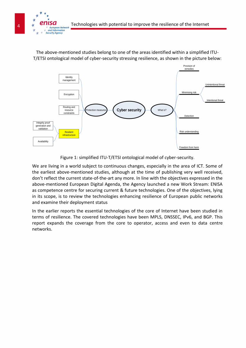
The above-mentioned studies belong to one of the areas identified within a simplified ITU-T/ETSI ontological model of cyber-security stressing resilience, as shown in the picture below:
Figure 1: simplified ITU-T/ETSI ontological model of cyber-security.
We are living in a world subject to continuous changes, especially in the area of ICT. Some of the earliest above-mentioned studies, although at the time of publishing very well received, don’t reflect the current state-of-the-art any more. In line with the objectives expressed in the above-mentioned European Digital Agenda, the Agency launched a new Work Stream: ENISA as competence centre for securing current & future technologies. One of the objectives, lying in its scope, is to review the technologies enhancing resilience of European public networks and examine their deployment status
In the earlier reports the essential technologies of the core of Internet have been studied in terms of resilience. The covered technologies have been MPLS, DNSSEC, IPv6, and BGP. This report expands the coverage from the core to operator, access and even to data centre networks.
Cyber security
Resilient
infrastructure
Routing and
resource
constraints
Encryption
Identity
management
Integrity proof
generation and
validation
Availability
Protection measures What is?
Freedom from harm
Risk understanding
Detection
Minimising risk
Provision of
remedies
Intentional threat
Unintentional threat

5 Technologies with potential to improve the resilience of the Internet
infrastructure
3 On the survey
3.1 Participant profile
Since the focus of the survey was resilient technologies in the Internet, the largest organization type was telecommunications and Internet operations (Internet and telecom operators, Internet exchange operators, registries, etc.) such as TDC, Janet, IIS, GRNET, NetNod, D-CIX, NFsi Telecomm, and OTEnet SA. The public sector was presented by ministries and regulators (Ministry of traffic, Finnish communications regulatory authority). The rest of the participants were divided by network vendors (Nokia Siemens Networks, Huawei), other enterprises (Sveriges Radio), research institutes and universities (National Research & Educational Network in Greece), and security units , e.g. defence Security and Defence Committee), security audit organizations Cyber Security Centre). Some of participants fall in two categories like Huawei’s (network vendor) Cyber Security Centre (security unit).
The participants in the study represented seven countries and 16 organizations. Most of the organizations operated in one country. Among multinational organizations there were three large (presence in 10 or more countries) and two smaller organizations. Both the network vendors were very large global enterprises.
Table 1: Participant profile.
0 1 2 3 4 5 6 7 8
Telecom and Internet operations
Network vendor
Enterprise
Reseach institutes and university
Public sector
Security unit
IT Service organization

6 Technologies with potential to improve the resilience of the Internet infrastructure
3.2 The purpose and scope of the report
The scope was divided in two main areas: Deployment status of selected SAN, LAN, and WAN resilience technologies were studied. The second area was supply chain integrity. The survey was conducted in three phases: Literature study, web based questionnaire and complementary Interview.
Internet resilience is a very wide area that includes core internet infrastructure such as internet exchanges, internet service provider’s network on multiple tiers and access networks. Also, when studying internet resilience the datacentres and server farms providing the application level services should be taken into account.
In this report we have divided internet infrastructure in four different technological, functional and architectural blocks. Currently widely used division of hierarchical internet structure was not applicable for this work due to layered nature of technologies so we have used a traditional partly geographical division to GAN, WAN, MAN, LAN and SAN.
SAN
DNS
IXP
Operator core: SDH/WDM/MPLS
Network
LAN
MAN
WAN
GAN
Operator access: ATM/EthernetOptical/xDSL-
network
Operatoraccess: Mobile
network
Figure 2 High level Internet structure.

7 Technologies with potential to improve the resilience of the Internet
infrastructure
GAN (Global Area Network) refers in this report the core of Internet consisting of interconnected large tier 2 and tier 3 carriers. The focus in resilience is in the interoperator routing and name service.
WAN (Wide Area Network/Metropolitan Area Network) refers hare to operator’s core network. The main technological components there are internal routing protocols, virtual paths and the underlying optical network with its resilient features.
MAN/LAN (Metropolitan/Local Area Network) means in this context the operator access network and the local network in the data centre or in customer premises. There are a large number of technologies increasing resilience of active components of the network as well as the physical lines. These technologies represent a different generations and levels of maturity. Newer technologies are still not settled, and there are a number of alternative technologies competing with each other.
SAN (Storage Area Network) technologies inside corporate networks and datacentres ensure that there is a fast and resilient communication channel between servers and storage devices.

8 Technologies with potential to improve the resilience of the Internet infrastructure
4 Technologies in Internet core (GAN)
4.1 Border Gateway Protocol (BGP)
The Border Gateway Protocol (BGP)1 is the protocol backing the core routing decisions on the Internet.
It maintains a table of IP networks or 'prefixes' which designate network reachability among autonomous systems (AS). It is described as a path vector protocol. BGP does not use traditional Interior Gateway Protocol (IGP) metrics, but makes routing decisions based on path, network policies and/or rule sets. For this reason, it is more appropriately termed a reachability protocol rather than routing protocol.
4.2 Secure BGP (S-BGP)
Secure BGP2 was introduced as an extension to BGP to protect against false routing updates. S-BGP applies strong authentication and authorization features to BGP based on public-key cryptography.
S-BGP introduces three major additions to BGP. First, a public key infrastructure (PKI) is introduced in the interdomain routing infrastructure to authorize prefix ownership and validate routes. The private keys are stored in S-BGP speakers, while the public keys are made available through a hierarchical PKI infrastructure. Second, it adds a new transitive attribute to BGP updates. That attribute verifies the authorization of routing UPDATEs, and avoids route modifications from intermediate S-BGP speakers. Third, IPSec can be applied, if routing confidentiality is required.
4.3 Secure origin BGP (soBGP)
Secure origin BGP3 was introduced as a lightweight alternative to S-BGP, mainly by researchers at Cisco Systems.
The objective of soBGP was to verify two issues of routing information, namely that an AS is the authoritative owner of a given prefix and to verify that that the advertising AS has at least one valid path to that destination.
soBGP utilizes three types of certificate for the required verification. soBGP routers use a topology database to validate received routes.
1 http://tools.ietf.org/html/rfc4271
2 The Internet Protocol Journal - Volume 6, Number 3 - Securing the Border Gateway Protocol
3 The Internet Protocol Journal - Volume 6, Number 3 - Securing BGP Through Secure Origin BGP

9 Technologies with potential to improve the resilience of the Internet
infrastructure
4.4 Multiprotocol Label Switching - Transport Profile (MPLS-TP4)
The MPLS-TP proposal contains a set of compatible technology enhancements to existing MPLS standards to extend the definition of MPLS to include support for traditional transport operational models.
This proposal adopts all of the supporting quality of service (QoS) and other mechanisms that are already defined within the standards, but also brings the benefits of path-based, in-band Operations, Administration, and Maintenance (OAM) protection mechanisms found in traditional transport technologies.
The MPLS-TP enhancements will increase the applicability of MPLS overall, allowing it to serve both the transport (access and core) and the services networks.
4.5 Domain Name System Security Extensions (DNSSEC)
The Domain Name System Security Extensions (DNSSEC5) is a suite of Internet Engineering Task Force (IETF) specifications for securing certain kinds of information provided by the Domain Name System (DNS) as used on Internet Protocol (IP) networks. It is a set of extensions to DNS which provide to DNS clients (resolvers) origin authentication of DNS data, authenticated denial of existence, and data integrity, but not availability or confidentiality.
4.6 Internet Protocol v6 (IPv6)
Internet Protocol version 6 (IPv66) is a new version of the Internet Protocol (IP) that is designed to succeed the older Internet Protocol version 4 (IPv4).
IPv6 specifies a new packet format, designed to minimize packet header processing by routers. Because the headers of IPv4 packets and IPv6 packets are significantly different, the two protocols are not interoperable. However, in most respects, IPv6 is a conservative extension of IPv4. Most transport and application-layer protocols need little or no change to operate over IPv6; exceptions are application protocols that embed Internet-layer addresses, such as FTP and NTPv3
4.7 Survey results
In the survey we also requested the respondents to comment on deployment of the technologies that were outside of this project but have been found key technologies in the previous studies and surveys. These technologies include MPLS, DNSSEC, IPv6 and S-BGP.
4 http://tools.ietf.org/html/rfc5317
5 http://tools.ietf.org/html/rfc2535
6 http://tools.ietf.org/html/rfc2460

10 Technologies with potential to improve the resilience of the Internet infrastructure
Table 2: Resilience technologies implementation
As the summary table clearly depicts, the implementation of IPv6 is either started or planned in all organisations taking part on the survey. The challenges in IPv4 shown in many studies before have been taken seriously and the implementation of IPv6 is on the way at least on the organisations on the survey.
Challenges in the recent years on DNS have also caused multiple organisations to deploy or plan to deploy DNSSEC, which enhances the security and the resilience of DNS architecture.
Responses on implementing MPLS are a bit surprising given that MPLS is considered to resolve a lot of layer 2 resilience and Spanning tree architecture challenges and also quality of service challenges. MPLS on the other hand is clearly an operator technology and corporate networks are not likely to implement MPLS n their networks which explains some if not all responses for not planning to implement MPLS.
Small portion of S-BGP implementations on plans are not surprising. BGP is generally considered to be robust and resilient and implementing extra security extensions would require clear risks to be motivated.
An encouraging result from the survey is that all organisations are implementing the technologies to improve resilience in their networks and deploying or planning to deploy IPv6 to overcome the challenges with IPv4.

11 Technologies with potential to improve the resilience of the Internet
infrastructure
5 Technologies in operator core (WAN)
5.1 Intermediate System To Intermediate System (IS-IS7)
IS-IS is a routing protocol designed to move information efficiently within a network.
It accomplishes this by determining the best route for datagrams through a packet-switched network. The protocol was defined in as a standard within the Open Systems Interconnection (OSI) reference design. IS-IS is often used as an internal routing protocol within service provider network backbones. IP routing support was added to IS-IS later, the IP-capable IS-IS is called Integrated IS-IS or Dual IS-IS.
Resilience can be achieved by using multiple paths between nodes and proper design and configuration. Failover times are usually from subseconds to few seconds.
5.2 Open Shortest Path First (OSPF8)
OSPF is an adaptive routing protocol for IP networks.
It uses a link state routing algorithm (similar than IS-IS) and falls into the group of interior routing protocols, operating within a single autonomous system. OSPF is very commonly used interior gateway protocol in enterprise networks and service provider network backbones.
Resilience can be achieved by using multiple paths between nodes and proper design and configuration. Failover times are usually from subseconds to few seconds.
5.3 Gateway Load Balancing Protocol (GLBP9)
Gateway Load Balancing Protocol (GLBP) is a Cisco proprietary protocol that attempts to overcome the limitations of existing redundant router protocols by adding basic load balancing functionality.
In addition to being able to set priorities on different gateway routers, GLBP allows a weighting parameter to be set. Based on this weighting (compared to others in the same virtual router group), ARP requests will be answered with MAC addresses pointing to different routers. Thus, load balancing is not based on traffic load, but rather on the number of hosts that will use each gateway router. By default GLBP load balances in round-robin fashion.
7 http://tools.ietf.org/html/rfc1142
8 http://tools.ietf.org/html/rfc2328, http://tools.ietf.org/html/rfc5340
9 http://www.cisco.com/en/US/docs/ios/12_2t/12_2t15/feature/guide/ft_glbp.html

12 Technologies with potential to improve the resilience of the Internet infrastructure
5.4 Hot Standby Router Protocol (HSRP10)
Hot Standby Router Protocol (HSRP) is a Cisco proprietary redundancy protocol for establishing a fault-tolerant default gateway, and has been described in detail in RFC 2281.
The protocol establishes a framework between network routers in order to achieve default gateway failover if the primary gateway should become inaccessible, in close association with a rapid-converging routing protocol like EIGRP or OSPF.
5.5 Virtual Router Redundancy Protocol (VRRP11)
Virtual Router Redundancy Protocol (VRRP) is a non-proprietary redundancy protocol described in RFC 5798 designed to increase the availability of the default gateway servicing hosts on the same subnet. This increased reliability is achieved by advertising a "virtual router" (an abstract representation of master and backup routers acting as a group) as a default gateway to the host(s) instead of one physical router.
5.6 Wavelength Division Multiplexing (WDM12)
WDM is a technology that uses laser and transmits several wavelengths of light simultaneously over a single optical fibre. Each signal travels within its unique colour band, which is modulated by the data. WDM has dramatically increased the carrying capacity of the fibre infrastructure of the telephone companies and other carriers.
Also known as "dense WDM" (DWDM), vendors have introduced systems that can support multiple wavelengths, each carrying 10 Gbps. That means terabits of data per second can travel over one optical strand.
For fast failover, the 50 ms optical alternate routing is available in ring topologies. Ring configurations using fully redundant fibre paths can be used.
5.7 Synchronous Digital Hierarchy (SDH13)
SDH is a standard technology for synchronous data transmission on optical media. It is the international equivalent of Synchronous Optical Network (SONET). Both technologies provide faster and less expensive network interconnection than traditional PDH (Plesiochronous Digital Hierarchy) equipment.
10
http://www.ietf.org/rfc/rfc2281.txt
11 http://www.ietf.org/rfc/rfc5798.txt
12 First mentioned by: O. E. Delange, "Wideband optical communication systems, Part 11-Frequency division multiplexing".
hoc. IEEE, vol. 58, p. 1683, October 1970
13 http://www.itu.int/rec/T-REC-G.707

13 Technologies with potential to improve the resilience of the Internet
infrastructure
SDH uses the following Synchronous Transport Modules (STM) and rates: STM-1 (155 megabits per second), STM-4 (622 Mbps), STM-16 (2.5 gigabits per second), and STM-64 (10 Gbps).
For fast failover, the 50 ms optical alternate routing is available in ring topologies. Ring configurations using fully redundant fibre paths can be used.

14 Technologies with potential to improve the resilience of the Internet infrastructure
6 Technologies in metropolitan and local area networks (MAN and LAN)
6.1 Spanning Tree (STP14)
The Spanning Tree Protocol (STP) is a network protocol that ensures a loop-free topology for any bridged Ethernet local area network.
The basic function of STP is to prevent bridge loops and ensuing broadcast radiation. Spanning tree also allows a network design to include spare (redundant) links to provide automatic backup paths if an active link fails, without the danger of bridge loops, or the need for manual enabling/disabling of these backup links.
6.2 Rapid Spanning Tree (RSTP15)
RSTP provides significantly faster spanning tree convergence after a topology change, introducing new convergence behaviours and bridge port roles to do this.
RSTP was designed to be backwards-compatible with standard STP.
While STP can take 30 to 50 seconds to respond to a topology change, RSTP is typically able to respond to changes within 3*Hello times (default: 6 seconds) or within a few milliseconds of a physical link failure.
6.3 Multiple Spanning Tree (MSTP16)
The Multiple Spanning Tree defines an extension to RSTP to further develop the usefulness of virtual LANs (VLANs).
This "Per-VLAN" Multiple Spanning Tree Protocol configures a separate Spanning Tree for each VLAN group and blocks all but one of the possible alternate paths within each Spanning Tree.
6.4 Transparent Interconnect of Lots of Links (TRILL17)
The basic premise of TRILL is to replace spanning tree as a mechanism to find loop free trees within layer 2 broadcast domains.
TRILL is a Proposed IETF Protocol implemented by devices called RBridges or Routing Bridges. TRILL combines the advantages of bridges and routers and is the application of link state routing to the VLAN-aware customer-bridging problem. TRILL devices (RBridges) run a link
14
http://standards.ieee.org/getieee802/download/802.1D-2004.pdf
15 http://standards.ieee.org/getieee802/download/802.1D-2004.pdf
16 http://standards.ieee.org/getieee802/download/802.1Q-2005.pdf
17 http://datatracker.ietf.org/doc/rfc6325/?include_text=1

15 Technologies with potential to improve the resilience of the Internet
infrastructure
state protocol amongst themselves. A link state protocol is one in which connectivity is broadcast to all the RBridges, so that each RBridge knows about all the other RBridges, and the connectivity between them. This gives RBridges enough information to compute pair-wise optimal paths for unicast, and calculate distribution trees for delivery of frames either to destinations whose location is unknown or to multicast / broadcast groups. The link state routing protocol used is IS-IS.
6.5 Shortest Path Bridging (SPB18)
Shortest Path Bridging is designed to replace Spanning Tree in providing loop prevention and load sharing between links.
It uses a link state protocol to advertise both topology and logical network membership. Packets are encapsulated at the edge either in mac-in-mac 802.1ah or tagged 802.1Q/802.1ad frames and transported only to other members of the logical network. Unicast and multicast is supported and all routing is on symmetric shortest paths. Many equal cost shortest paths are supported.
6.6 Ethernet Ring Protection Switching (ERPS19)
ERPS Provides ring topology redundancy for Ethernet.
Ethernet Ring Protection Switching, or ERPS, is an effort at ITU-T under G.8032 Recommendation to provide sub-50ms protection and recovery switching for Ethernet traffic in a ring topology and at the same time ensuring that there are no loops formed at the Ethernet layer. G.8032v1 supported a single ring topology and G.8032v2 supports multiple rings/ladder topology.
6.7 Resilient Packet Ring (RPR20)
Resilient Packet Ring (RPR), also known as IEEE 802.17, is a standard designed for the optimized transport of data traffic over optical fibre ring networks.
It is designed to provide the resilience found in SONET/SDH networks (50 ms protection) but, instead of setting up circuit oriented connections, provides a packet based transmission, in order to increase the efficiency of Ethernet and IP services.
18
http://www.ieee802.org/1/pages/802.1aq.html
19 http://tools.ietf.org/html/rfc3619
20 http://www.ieee802.org/17/

16 Technologies with potential to improve the resilience of the Internet infrastructure
6.8 Ethernet Automatic Protection Switching (EAPS21)
ERPS Provides ring topology redundancy for Ethernet.
Ethernet Automatic Protection Switching (EAPS) is Extreme Networks’ solution for fault-tolerant Layer 2 ring topologies. EAPS is responsible for a loop-free operation and a sub-second ring recovery. EAPS was created to solve slow recovery times inherent to STP, in essence replacing STP in ring topologies. Although STP and EAPS use a similar mechanism to avoid network loops, EAPS provides much more control, resilience and flexibility.
6.9 Resilient Ethernet Protocol (REP22)
REP is a Cisco proprietary protocol that provides a faster alternative to Spanning Tree Protocol (STP).
REP provides a way to control network loops, handle link failures, and improve convergence time. REP controls a group of ports connected in a segment, ensures that the segment does not create any bridging loops, and responds to link failures within the segment. REP provides a basis for constructing more complex networks and supports VLAN load balancing.
6.10 Link Aggregation Control Protocol (LACP23)
Link aggregation or trunking or link bundling or Ethernet/network/NIC bonding or NIC teaming are computer networking umbrella terms to describe various methods of combining (aggregating) multiple network connections in parallel to increase throughput beyond what a single connection could sustain, and to provide redundancy in case one of the links fails.
Within the IEEE specification the Link Aggregation Control Protocol (LACP) provides a method to control the bundling of several physical ports together to form a single logical channel. LACP allows a network device to negotiate an automatic bundling of links by sending LACP packets to the peer (directly connected device that also implements LACP)
6.11 InfiniBand24
InfiniBand is an industry-standard specification that defines an input/output architecture used to interconnect servers, communications infrastructure equipment, storage and embedded systems.
InfiniBand is a true fabric architecture that leverages switched, point-to-point channels with data transfers today at up to 120 gigabits per second, both in chassis backplane applications
21
http://tools.ietf.org/html/rfc3619
22 http://www.cisco.com/en/US/prod/collateral/switches/ps6568/ps6580/prod_white_paper0900aecd806ec6fa.pdf
23 http://grouper.ieee.org/groups/802/3/ad/index.html
24 http://www.infinibandta.org/

17 Technologies with potential to improve the resilience of the Internet
infrastructure
as well as through external copper and optical fibre connections. The InfiniBand specification defines an interconnect technology for servers and storage that changes the way data centres are built, deployed and managed.
InfiniBand is focused on providing a very specific type of interconnect over a very high reliability line of fairly short distance. The connecting infrastructure is needed to be very resilient.
6.12 Mobile Packet Access (3G, 4G and Wimax25)
Mobile Packet Access networks provide mobile Internet access and backup connectivity with relatively high speeds and low cost.
Mobile Packet Access networks have been gaining popularity as an access network and a backup connectivity solution due to increase in data transfer speed and coverage. Mobile IP connectivity is provided by operator networks and allows IP level connectivity to Internet or between sites via Mobile network operator’s mobile packet core network.
Mobile Packet Core networks are resilient due to duplication of central network elements and the usage of resilient switching and routing technologies. Mobile network radio coverage is resilient by design and robustness has been further enhanced with redundancy technologies and protocols to provide QoS, failover, and duplication.
25
http://grouper.ieee.org/groups/802/16/

18 Technologies with potential to improve the resilience of the Internet infrastructure
7 Technologies in storage area (SAN)
7.1 Fibre Channel (FC26)
Fibre Channel is a high-speed transport technology used to build storage area networks (SAN). It is primarily used for transporting SCSI traffic between servers and disk storage arrays. The Fibre Channel Protocol (FCP) serializes SCSI commands into Fibre Channel frames. The Fibre Channel is defined for speeds at 1G, 2G, 4G, 8G, 10G and 16G.
FC resilience can be achieved with using multiple connections, for example from host to two different FC switches, which are interconnected. The failover times are usually dependent on manufacturer and configurable timers, so they vary by default.
iSCSI resilience can be achieved by fast IP routing protocols and other IP routing -based resilience mechanisms. Failover times are usually from subseconds to few seconds.
26
http://tools.ietf.org/html/rfc2625

19 Technologies with potential to improve the resilience of the Internet
infrastructure
8 Summary of technologies
Table 3 List of technologies with their classification information.
Technology
(short name)
Technology
(full name)
OSI
layerPopularity Maturity
Standard/
specification
Status of
standard/spec.
Date of
specification
BGP Border Gateway Protocol L3 Majority State of the art RFC 4271 Standard 2006
S-BGP Secure BGP L7 Not used Leading edgedraft-clynn-s-bgp-
protocol-01.txtInternet draft 6/2003
so-BGP Secure origin BGP L7 Not used Bleeding edgedraft-white-sobgp-
architecture-02Internet draft 6/2006
DNSSECDomain Name System
Security ExtensionsL7 Marginal Leading edge
RFC 3833, 4398, 4033,
4034, 4035Standard 2004-2006
IPv6 Internet Protocol v6 L3 Marginal Leading edge RFC 2460 Standard 1998
IS-ISIntermediate System To
Intermediate System L3 Majority State of the art
ISO 10589, RFC 1142,
RFC 1195, RFC 5305
Standard (ISO)
Proposed std
1992 (ISO), 1990-
2008 (IETF)
OSPF Open Shortest Path First L4 Marginal State of the artRFC 2328, RFC 5340,
RFC 3630, RFC 5329Standard 1998-2008
MPLS-TPMultiprotocol Label
Switching - Transport L2-L4 Not used Bleeding edge
RFC 5317, RFC 5654, RFC
5860
Proposed
standard2009 - 2010
VRRPVirtual Router
Redundancy ProtocolL3 Popular State of the art RFC 5798 Standard 1999
GLBPGateway Load Balancing
ProtocolL3 Popular State of the art Cisco Proprietary 2008
HSRPHot Standby Router
ProtocolL3 Popular State of the art Cisco Proprietary 1994
WDMWavelength Division
Multiplexing L1 Everywhere State of the art
ITU-T Rec. G.671,
ITU-T Rec. G.694.2Standard 1996, 2003
SDHSynchronous Digital
Hierarchy L1 Popular Dated
ITU-T G.701-G.707, G.780,
G.803Standard 1988 - 2010
STP Spanning Tree L2 Marginal Dated IEEE 802.1D Standard 1990
RSTP Rapid Spanning Tree L2 Majority State of the art IEEE 802.1w Standard 2001
MSTP Multiple Spanning Tree L2 Majority State of the art IEEE 802.1s Standard 2002
TRILLTransparent Interconnect
of Lots of Links L2 Marginal Bleeding edge RFC 6327
Proposed
standard6/2011
SPB Shortest Path Bridging L2 Not used Bleeding edge IEEE 802.1aq Draft standard 2011
ERPSEthernet Ring
Protection Switching L2 Marginal Bleeding edge
ITU-T G.8032v1
ITU-T G.8032v2Standard 3/2010
RPR Resilient Packet Ring L2 Marginal State of the art IEEE 802.17 Standard 2004
EAPSEthernet Automatic
Protection Switching L2 Marginal Bleeding edge
RFC 3619,
Extreme ProprietaryInformational 10/2003
REPResilient Ethernet
Protocol L2 Marginal Bleeding edge Cisco Proprietary
LACPLink Aggregation Control
ProtocolL2 Majority State of the art IEEE 802.1ad Standard 2000
InfiniBand InfiniBand L1-L4 Marginal Bleeding edgeCompaq, IBM, HP,
Intel, Microsoft, SunIndustry std 1999
3G, 4G and
WimaxMobile Packet Access L1-L2 Majority State of the art
IEEE 802.16e-2005,
3GPP Releases 8-11Standard 2005, 2008-2011
FC Fibre Channel L1-L4 Majority State of the artINCITS T11,
ANSI FC-PI-5Standard 1994-2008

20 Technologies with potential to improve the resilience of the Internet infrastructure
8.1.1 Explanation of columns in table 3
8.1.1.1 Popularity
Significance of technology increases with its popularity. Popularity was dealt in four levels: Not used: Technology is not used
Marginal: Technology is used in marginal amount of potential networks
Popular: Technology is fairly popular, but is still in use in less than 50% of potential
networks.
Majority: Technology is used in majority of networks
Everywhere: Technology is used virtually everywhere.
8.1.1.2 Maturity
Bleeding edge technology: a technology that is so new that it could have a high risk of
being unreliable and may incur greater expense in order to use it.
Leading edge: A technology that has proven itself in the marketplace but is still new
enough that it may be difficult to find knowledgeable personnel to implement or support
it.
State of the art: Everyone agrees that a particular technology is the right solution.
Dated: Technology is still useful, still sometimes implemented, but a replacement leading
edge technology is already available.
Obsolete: Technology has been superseded by state-of-the-art technology, maintained but
no longer implemented.
8.1.1.3 Standardization
The specification of the technology may be an open standard or used by a certain vendor.
8.1.1.4 Place in Internet
Referring to previous discussion of Internet structure the typical location (GAN, WAN, MAN, LAN, SAN) of the technology in Internet in expressed.

21 Technologies with potential to improve the resilience of the Internet
infrastructure
9 Chosen technologies
9.1 Criteria for evaluation of technologies
All the technologies were evaluated against four properties: Popularity, maturity, standardization, and place in the Internet. A score was given to all the properties as presented below. A more popular technology got more points that a less popular one. Leading edge and state of the art got more appreciation than new born or dated technology. A standard technology was considered to be more valuable than vendor specific. Technologies closer to core of Internet were considered more valuable in terms of Internet resilience than those in customer premises. The properties were weighted so that standardization and the place in Internet were given more weight than popularity and maturity.
All the technologies were given a total score, which was the sum of weighted scores of properties. Technologies related to BGP, IPSEC, MPLS, and IPv6 are discussed in previous reports, and they won’t be selected for a closer examination in this report.
One key technology in each major part of the Internet was chosen. Since the GAN technologies were already studied in previous reports two technologies in different roles were chosen in WAN.
The chosen technologies were: IS-IS: the most popular internal routing protocol among
operators.
VRRP: Redundancy protocol for establishing a fault-tolerant default gateway
RSTP: Protocol for LAN redundancy.
FC: Resilient Storage area network.
Note that VRRP was chosen instead of WDM, although WDM has higher score. VRRP is a pure resilience technology, but in WDM resilience is only an optional feature.
Weights Score Popularity Score Maturity Score Standardization Score Place Score
Popularity 1 Not used 1 Bleading edge 2 Standard 5 GAN 4
Maturity 1 Marginal 2 Leading edge 4 Prorietary 0 WAN 3
Standardization 4 Popular 3 State of the art 4 MAN/LAN 2
Place 4 Majority 4 Dated 1 SAN 1
Everywher
e
5 Obsolite 0
Place in
InternetImportance Technology
GAN 44 BGP
GAN 42 DNSSEC
GAN 42 IPv6
GAN 41 S-BGP
GAN 39 so-BGP
GAN 35 MPLS-TP
WAN 40 IS-IS
WAN 41 WDM
WAN 39 VRRP
WAN 38 OSPF
WAN 36 SDH
WAN 19 GLBP
WAN 19 HSRP
MAN/LAN 28 RSTP
MAN/LAN 28 MSTP
MAN/LAN 28 LACP
MAN/LAN 28 3G, 4G and
MAN/LAN 26 RPR
MAN/LAN 24 TRILL
MAN/LAN 24 ERPS
MAN/LAN 24 EAPS
MAN/LAN 23 STP
MAN/LAN 24 InfiniBand
MAN/LAN 23 SPB
MAN/LAN 4 REP
SAN 32 FC

22 Technologies with potential to improve the resilience of the Internet infrastructure
9.2 IS-IS
9.2.1 Overview of IS-IS routing protocol
9.2.1.1 About IS-IS protocol
Intermediate System to Intermediate System (IS-IS) was originally defined in ISO 10589 standard as a protocol for routing datagrams in the Connectionless Network Service (CLNS) using Network Service Access Point (NSAP) type of addresses on layer 3 of the OSI model. Later changes in the IS-IS protocol made it possible to use IS-IS for routing IP traffic, and this updated version of IS-IS also became an IETF Internet Standard as RFC 1142. Today it remains a widely used packet routing protocol in large Internet service provider core networks.
IS-IS is a network routing protocol, which determines the best paths for datagrams to follow across a packet-switched network. IS-IS belongs to the group of Interior Gateway Protocols (IGPs), which means that it is used inside an administrative domain in contrast to Exterior Gateway Protocols (EGPs), which in turn route traffic between these domains. An administrative domain is a collection of networks under the control of a single administrative entity. Routing Information Protocol (RIP) and Open Shortest Path First (OSPF) are other well-known IGP routing protocols.
IS-IS is a link-state routing protocol meaning that every network router stores and updates its own database of the full network topology by collecting routing information updates flooded by other routers in the network. This information exchange is done in the form of Link State Packets (LSPs), which contain information about connected networks from each router. Dijkstra's shortest-path first algorithm is then used to determine the best routes to each destination. These routes are used whenever datagram routing decisions must be made in the network router.
Link-state routing protocols employ a hierarchical network design. The network is divided into separate areas to minimize the number of routing table entries. The impact of topology changes is localized by stopping LSPs at area borders.
Routers are designated in the following classes: Level 1 (intra-area) routers exchange routing information with other Level 1 type routers
within their own area. A Level 1 router aggregates a topology database from updates sent by other routers in its own area. These may be other Level 1 or Level 1-2 routers in that same area.
Level 2 (inter-area) routers communicate routing updates with other Level 2 routers across area borders. IS-IS backbone is thus formed of a series of Level 2-capable routers, and these Level 2 routers can be inside different areas. Level 2 routers have neighbours in the same or different areas, and collect a link-state database for inter-area routing. Level 2 routers do not know about the Level 1 topologies of their own areas.
Level 1-2 (both) type routers Level are able to communicate with both types of routers, and have a special role in connecting the Level 2 backbone routers to intra-area Level 1 routers.

23 Technologies with potential to improve the resilience of the Internet
infrastructure
Level 1-2 routers keep two separate topology databases and run two separate SPF algorithm instances. They are able to perform both inter-area as well as intra-area routing.
Figure 3: IS-IS routers connecting several areas
IS-IS protocol communication happens in the form of four general packet types: IS-IS Hello (IIH) is used to find neighbors to form adjacencies with them.
Link State Packet (LSP) is used to share link state information between routers that have an adjacency between them.
Complete Sequence Number PDU (CSNP) includes all the LSPs in the topology database of a router. Routing information synchronization is ensured using CSNPs.
Partial Sequence Number PDUs (PSNP) are used to request specific LSPs and acknowledge their reception.
These PDUs can be used on Level 1 and Level 2 adjacencies.
One of the routers on a LAN will get elected as a Designated Intermediate System (DIS). The DIS handles the synchronization of link state databases among the routers on the LAN. The selection of a DIS on a broadcast network reduces the amount of necessary flooding, since all routers on a LAN form an adjacency with the DIS and adjacencies with all routers on a LAN are not needed.
9.2.1.2 IS-IS compared to the OSPF routing protocol
OSPF does not have the underpinnings of ISO standardization and was developed by IETF with IP packet routing in mind from the beginning. It is very similar to IS-IS and they are both categorized as link-state routing protocols. Both OSPF and IS-IS employ the SPF algorithm for route calculation, and distribute network topology information in the form of LSPs.
Area 2
Area 3 Area 1
Level 1
Level 1 Level 1 Level 1
Level 1-2 Level 1-2
Level 1-2 Level 1-2
Level 2

24 Technologies with potential to improve the resilience of the Internet infrastructure
OSPF is much more common in smaller enterprise networks and is often thought as easier to configure and operate by network administrators. This is mainly because of the cumbersome CLNS addresses that IS-IS requires to identify routers, even if only routing IP traffic. CLNS addresses are needed because IS-IS communicates the routing updates using a specific CLNS protocol data unit. OSPF also has better hardware support than IS-IS.
Area design for IS-IS is different from that used in OSPF. IS-IS does not have a single backbone area like OSPF. Instead, the IS-IS backbone is formed of several interconnected Level 2-capable routers. These routers can be in different areas forming a contiguous chain. In contrast, backbone networks built using OSPF have a spider-web style topology, where the network is based on a central backbone area with other areas attached to it.
Another difference is the way routers belong to areas. OSPF routers have area borders inside of them and each router link belongs to an area. IP routers have addresses assigned to the interfaces, whereas there is one NSAP address per router in the CLNS architecture.
Compared to OSPF, IS-IS also has better support for routing other protocol traffic besides IP, because its original design was based on OSI CLNS addressing. 9.2.2 Resilience provided by IS-IS routing protocol
9.2.2.1 Rules for adjacency building
Level 1 routers that connect to each other over a network segment will need to have the connecting interfaces configured with the same area in order to form a Level 1 adjacency. In case the two routers are configured with different areas, they need to be configured as Level 2, in order for the two to form an adjacency.
A link, an area or an entire administrative network domain can be configured with an authentication password, which will further limit unintentional adjacencies.
9.2.2.2 Link state information refreshing
LSPs have a remaining lifetime which starts at 1200 seconds, and must be periodically refreshed by the LSP originator router or the LSPs in question will become purged from the database.
Each LSP also includes a checksum. If the checksum is deemed incorrect by the receiving router, the LSP is purged and a new one is requested from the originating router.
9.2.2.3 Reliable LSP flooding
Any change in the link states of a router means that updated LSPs need to be resent to the network to update other routers of the changed network topology. Newer LSPs are tagged with a larger sequence number and are this way recognized by the other routers.
Although LSP reception is acknowledged on point-to-point links in the form of a PSNP, there is no acknowledgment to individual LSPs in LANs. A router will notice missing LSPs by comparing the full LSPs list in received CSNPs to its own database. If any LSPs are not found from the

25 Technologies with potential to improve the resilience of the Internet
infrastructure
local database, they are requested using a PSNP which identifies the missing LSPs.
9.2.2.4 Redundant Level 1-2 routers
In a well-designed IS-IS network there will be more than one Level 1-2 router in any Level 1 area. This is done to prevent area isolation in the case of a failure in Level 1-2 routers.
Figure 4: Alternative routing to Level 2 area through another Level 1-2 router
In the example in Image 2, as the Level 2 adjacency fails on the first Level 1-2 router, it will install a default route pointing to the second Level 1-2 router. It will reflood the area with updated LSPs and the Level 1 routers in the area remove their default route to the first Level 1-2 router and replace it with a default route to the second Level 1-2 router.
9.2.2.5 Load balancing between several routes
The IS-IS protocol is also able to keep track of several equal-cost paths (computed through the SPF calculation) to a certain destination. This set of next-hops is used for load balancing traffic to that network destination.
9.2.2.6 IS-IS adjacency processing
Half-broken links that “flap” between up and down states need to be handled gracefully by the routing protocol. Modern IS-IS implementations are able to apply damping logic in transitioning between adjacency states, so that the network is not overwhelmed by frequent updates resulting from a “flapping” link. Typical IS-IS routers use a so called hold timer to artificially delay bringing up a link. Links that have flapped frequently in the past will have a higher hold timer value than links that have not experienced flapping.
Another IS-IS protocol behaviour which has an effect on network resilience against failures, is network liveliness detection. Frequent Hello messages will allow fast detection of lost
Area 2
Area 1
Level 1 Level 1
Level 1-2
Level 2 Level 2
Level 1-2

26 Technologies with potential to improve the resilience of the Internet infrastructure
adjacencies. IS-IS implementations today allow sub-second Hello timers to be set in routers, so that fast detection of adjacency state is possible. 9.2.3 IS-IS Security
9.2.3.1 Security against malicious threats
There are various kinds of threats for a routing protocol network information disclosure to the attacker
decepting the routing protocol into accepting routing messages from the attacker
disrupting the routing protocols proper functionality using, for example, a denial-of-service attack
attacker gaining control of the routing protocol in any of the network routers
IS-IS protocol has security features which reduce the possibility of a successful attack. Since IS-IS protocol messages are not carried in IP packets, it prevents an attacker from
sending faked routing protocol messages from external sources. An attacker is required to have physical access to the target router or one of its links.
Enabling authentication forces two neighbouring routers to prove their identity to each other. In the case of a failed authentication, no routing protocol messages are accepted from the neighbour. An attacker must gain knowledge of the shared authentication password used in the network before making any successful attack on the routing protocol.
Part of normal IS-IS protocol behaviour is that a router will fight back to any routing information that it deems incorrect. Each time a router receives a routing information message that it supposedly originated, it will compare the information with its own database. If the link-state information is incorrect, the router will send out new LSPs to flush the bogus LSP information from the network.
9.2.4 Deployment
9.2.4.1 Current status
Today IS-IS holds its position in large service providers’ backbone networks. Main reason for this is good knowledge of IS-IS configuration among ISP network engineers and good extensibility of the protocol.
The IS-IS routing protocol has proven easier to extend than OSPF, and new features, such as MPLS TE and IPv6, are often supported in IS-IS considerably earlier than in OSPF. Partly for this reason it is broadly deployed within the large ISP market.
Extensions are easier to implement in IS-IS because protocol information is formatted as a series of Type-Length-Values (TLVs). Implementing an extension means simply adding new TLV values to the protocol messages, whereas it is much harder to update OSPF messages with new parameters. IS-IS handles unknown TLVs in a more graceful way than OSPF. Upon

27 Technologies with potential to improve the resilience of the Internet
infrastructure
receiving an LSP containing unknown TLVs, IS-IS protocol ignores the unknown values and passes the message to the neighbouring routers. OSPF routers simply drop unrecognized LSA messages.
Also, since IS-IS is not an IP protocol, there are no dependencies on IP and new protocol support is easier to implement than for OSPF. This is why IS-IS is seen as a more flexible and future-proof routing protocol than OSPF.
9.2.4.2 Future deployment status
The IS-IS protocol is seeing much development in the Traffic Engineering (TE) area, and multiple RFCs have been written of IS-IS TE extensions. This will allow it to further establish itself as a core network routing protocol for large ISP networks. 9.2.5 Survey results
9.2.5.1 Deployed Intra-AS routing protocols
Intra-AS routing is essential for quick recovery of the networks in the case of IP layer topology change. The most common routing protocols in the survey respondents networks are IS-IS and OSPF with equal share. Our initial assumption that IS-IS is more commonly deployed in telecom and operator environments and OSPF is more popular in corporate networks is not, based on this relatively small survey, the case and both protocols hold equal share in all environments.
Figure 5: Intra-AS routing protocols

28 Technologies with potential to improve the resilience of the Internet infrastructure
An interesting find was that no other intra-AS routing protocols were used in the respondents networks. This implies that in most of the networks are not homogenous in the choice of router and firewall vendors. If homogenous Cisco-networks were implemented, obvious choice for routing protocol would be EIGRP due to its in many cases superior features comparing to IS-IS and OSPF.
The choice between OSPF and IS-IS seems to be only a matter of taste and familiarity of the protocol and the importance of the traffic engineering aspects of IS-IS was not verified in the survey findings.
9.2.5.2 Where the routing protocols are used
Intra-AS routing protocols are used in every backbone network in the survey. This is expected since the backbone network typically require automatic path discovery and routing information has to be efficiently converged throughout the network to keep consistent service on the IP layer regardless of actual backbone network implementation. Even if the backbone service is provided with MPLS the underlying IP network requires routing protocol implementation for flag distribution.
In addition to backbone networks interior routing protocols are implemented in the datacentre and access networks, although with a bit less coverage.
Figure 6: Where interior routing protocols are used

29 Technologies with potential to improve the resilience of the Internet
infrastructure
The reason for not using routing protocols in access or datacentre networks is likely that the networks are layer 2 which does not require routing protocol, only first hop redundancy.
9.2.5.3 The most important aspect of routing protocols
According the survey the most important aspect of interior routing is rapid convergence. This is very much expected since the logical domains of interior routing protocol implementation are constantly changed. In backbone and datacentre networks there are typically networks and routers added, other layer 3 changes implemented and links in and out of service constantly which requires flexibility and short convergence times from the routing protocol.
Support for load balancing and ease of implementation are also considered to be very important when choosing and implementing intra-AS routing protocol. In all the backbone and datacentre networks there are typically redundant paths between any two end points. For the bandwidth to be fully utilized and the path selection to be optimized the routing protocol will have to support more than one path. Both most commonly used interior routing protocols support equal cost load balancing between multiple paths only and load balancing between unequal cost paths require extra tweaking on the implementation.
Dual stack support (support for both IPv4 and IPv6) was also among the survey responses, which implies at least some interest in IPv6 implementation. The reason for only one respondent mentioning dual stack is likely that the organizations have separate plans for implementing IPv6 and the support for IPv6 from the routing protocol is evaluated separately from current implementations.
Support for hierarchical routing architecture or security aspects were not considered to be among the most important aspects.
9.2.5.4 Testing and monitoring IS-IS
In the survey we also tracked responses on the monitoring and testing of the routing protocol performance and the convergence of the routing protocol. The responses indicate that active testing and monitoring is performed in the routed networks. Active monitoring and testing implies that the choice of routing protocol and its implementation is considered an important part in implementing and maintaining a resilient IP network infrastructure.
9.2.5.5 Drawbacks of IS-IS
No significant drawbacks were found in IS-IS protocol and its implementation. IS-IS is therefore found to be a solid choice for routing protocol. It is mature technology and is constantly evolving to respond the changing needs of the networks in use currently.
9.2.6 Summary
The IS-IS routing protocol and OSPF are two very similar link state routing protocols, and each one has found its place – OSPF in enterprise networks and IS-IS in large operator core

30 Technologies with potential to improve the resilience of the Internet infrastructure
backbone networks. In spite of their age, both protocols are still actively developed and will stay in the network engineer’s toolkit in the foreseeable future.
9.3 VRRP
9.3.1 Overview of VRRP
9.3.1.1 About First Hop Redundancy
On any access or datacentre network there is a gateway into the network for service access and out from the network for return path. This gateway is usually either statically assigned or learned and advertised by a routing protocol.
A First Hop Redundancy Protocol is a computer networking protocol which is designed to protect the default gateway used on a subnetwork by allowing two or more routers to provide backup for that address. In the event of failure of an active router, the backup router will take over the address, usually within a few seconds. In practice, such protocols can also be used to protect other services operating on a single IP address, not just routers.
Figure 7: First Hop Redundancy principle
9.3.1.2 VRRP Overview
The VRRP protocol achieves first hop redundancy with a creation of virtual routers, which are an abstract representation of multiple routers, i.e. master and backup routers, acting as a group. The default gateway of a participating host is assigned to the virtual router instead of a physical router. If the physical router that is routing packets on behalf of the virtual router fails, another physical router is selected to automatically replace it. The physical router that is forwarding packets at any given time is called the master router.

31 Technologies with potential to improve the resilience of the Internet
infrastructure
VRRP provides information on the state of a router, not the routes processed and exchanged by that router. Each VRRP instance is limited, in scope, to a single subnet. It does not advertise IP routes beyond that subnet or affect the routing table in any way.
Figure 8: LAN Active gateway selection
9.3.2 Resilience provided by VRRP
VRRP uses multiple mechanisms to assure that the gateway is available and usable at all times. This has a definitive effect on resilience of the access networks and service provider networks.
9.3.2.1 Default gateway election
Only one of the gateways can be used for any one packet destined outside the LAN or VLAN in question. This requires a mechanism for electing from multiple gateways inside the VRRP group.
To fool the hosts in the LAN only the master router in each VRRP group must respond to ARP queries. From ARP responses and gratuitous ARP queries the switches learn the virtual mac address correctly. Since the mac address table timeout is in the order of 5 minutes, the switches need to see the virtual mac as a source address in short intervals. This is guaranteed by the fact that the master router sends all of its VRRP hellos using the virtual mac as the source mac address. VRRP hellos are sent by default every second.
For each VRRP group that together form a Virtual Router there must be exactly one master router. The rules governing election of master are as follows:

32 Technologies with potential to improve the resilience of the Internet infrastructure
If the VR IP address is the real IP address of one of the routers in that group, the owner of the address will always be the master. There is no workaround to this rule, only the address owner gets VRRP priority 255.
If the VR IP address is separate from the real interface addresses of the participating routers, the router with the highest priority is elected master. Priority is communicated in the VRRP hello message. The default priority should be 100 and it is configurable (values 1 – 254) per VRRP group.
If all routers have the same priority, the one to initialize first (to be configured first) will assume the master role, since it doesn’t hear any master advertisements. When the rest of the routers with the same priority become operational, they assume backup roles since there is an active master with equal priority.
The hosts have their default route pointing to the virtual router’s IP address. They query for the corresponding mac address using ARP as normal. Only the master router in the group answers to the ARP requests for the virtual IP. The master router gets all Ethernet frames destined for the virtual mac and handles all traffic for the group it is a master for.
The redundant router is called a backup router and it stays quiet for as long as it can receive the master router’s hello messages. Each heard hello has a field called advertisement interval. The dead interval for each heard hello is calculated by multiplying the advertisement interval by 3.
The VRRP hellos are sent as multicast IP packets to the VRRP allocated group address 224.0.0.18. Multicasts should always be flooded or forwarded by the switched network to all routers in the VRRP group.
9.3.2.2 VRRP Switchover
In case of a failure another gateway must assume the responsibility to forward packets and take the role of a master router in the group.
Fault tolerance is based on the premise ”no news is bad news”. If no hellos are heard by the routers in VRRP group, the backup will eventually (after dead interval) assume the master role.
If the master router crashes it’s too late after that for it to notify the backup that it should take over. This is why ”no news is bad news” is used in all fault tolerant environments. The default dead interval is 3 times the advertisement interval and since the advertisement interval is 1 second by default, the backup declares itself as the master after 3 seconds of silence.
After transitioning itself to master status the old backup router sends a gratuitous ARP query to the network. Since the ARP query is a broadcast it will be flooded through all switches in that VLAN. Thus all switches re-learn the virtual mac address behind another port.
The new master will start sending VRRP hellos setting the source mac for them as the virtual mac.

33 Technologies with potential to improve the resilience of the Internet
infrastructure
The hosts don’t recognize any change. Their ARP table is undisturbed and there is no need for them to ever change the IP to mac address mapping for the virtual IP and virtual mac. Of course, all packets sent by the router could be black-holed for 3 seconds, if the switch still thinks the virtual mac is behind the port leading to the previous master router. If the router really crashed, however, the port would have gone down and the virtual mac would have been deleted from the mac address table.
The RFC for VRRP specifies that the shortest advertisement interval is 1 second making the shortest convergence time achievable little over 3 seconds. Cisco has made extensions to this. All VRRP group member routers can be configured to treat the advertisement interval field in the VRRP hello packet as number of milliseconds. Thus between Cisco routers one can have shorter convergence times.
Figure 9: VRRP Switchover
9.3.2.3 VRRP pre-emption
After master failure the backup router will assume responsibilities for packet forwarding. Once the original master router comes back on-line it will pre-empt the current master. Pre-empting means resuming the master role when a router recognizes that the received VRRP hello contains a lower priority than its own.
Pre-emption enhances resilience in enabling the use of optimal paths to and from the LAN. Also pre-emption enables rolling upgrades or maintenance on the gateways which in turn increases overall reachability of the network.

34 Technologies with potential to improve the resilience of the Internet infrastructure
9.3.2.4 VRRP interface tracking
The VRRP Object Tracking feature extends the capabilities of the Virtual Router Redundancy Protocol (VRRP) to allow tracking of specific objects within the router that can alter the priority level of a virtual router for a VRRP group. For example, a WAN interface can be tracked and if it goes down, then the priority of the VRRP group can be lowered, which may allow another VRRP router to become the new group master virtual router. The tracking process periodically polls the tracked objects and notes any change of value. The changes in the tracked object are communicated to interested client processes, either immediately or after a specified delay. The object values are reported as either up or down.
If a VRRP group is the IP address owner, its priority is fixed at 255 and cannot be reduced through object tracking.
Object tracking is an usually an independent process that manages creating, monitoring, and removing tracked objects such as the state of the line-protocol of an interface. Clients such as VRRP register their interest with specific tracked objects and act when the state of an object changes.
The tracking process periodically polls the tracked objects and notes any change of value. The changes in the tracked object are communicated to interested client processes, either immediately or after a specified delay. The object values are reported as either up or down.
9.3.3 VRRP Security
VRRP security relies on authenticating the VRRP protocol messages.
9.3.3.1 Authentication
VRRP ignores unauthenticated VRRP protocol messages. The default authentication type is text authentication. You can configure VRRP text authentication, authentication using a simple MD5 key string, or MD5 key chains for authentication.
MD5 authentication provides greater security than the alternative plain text authentication scheme. MD5 authentication allows each VRRP group member to use a secret key to generate a keyed MD5 hash of the packet that is part of the outgoing packet. A keyed hash of an incoming packet is generated and if the generated hash does not match the hash within the incoming packet, the packet is ignored. The key for the MD5 hash can either be given directly in the configuration using a key string or supplied indirectly through a key chain.
A router will ignore incoming VRRP packets from routers that do not have the same authentication configuration for a VRRP group. VRRP has three authentication schemes:
no authentication
Plain text authentication
MD5 authentication

35 Technologies with potential to improve the resilience of the Internet
infrastructure
VRRP packets will be rejected in any of the following cases: The authentication schemes differ on the router and in the incoming packet.
MD5 digests differ on the router and in the incoming packet.
Text authentication strings differ on the router and in the incoming packet.
9.3.4 Challenges in VRRP implementation
9.3.4.1 Sub-optimal paths from LAN
There can be 255 VRRP groups (and Virtual Routers) per router. A router may be master in one group backup in another making it possible to share the packet switching load. Load can be shared within one IP network, half the hosts in one VLAN could use one master and the other half another. Load sharing is typically set up between VLANs (IP subnets), though. One router would be the master in one network and backup in another network (another VLAN), for instance. This also requires the routers to have an interface in all VLANs that it acts as a VRRP router for.
There should be no dynamic routing between the hosts that use the Virtual Router IP address as their default and the routers. Although not originally envisioned, VRRP is also used in environments where there are static routes between routers. 9.3.5 Deployment
9.3.5.1 Current status
This protocol is very commonly deployed in corporate and datacentre networks where a standard protocol is required for first hop redundancy.
9.3.5.2 Future deployment status
The main contestants for an alternate method to provide first hop redundancy are
Hot Standby Routing Protocol (HSRP, Cisco proprietary)
Cisco proprietary redundancy protocol for establishing a fault-tolerant default
gateway
Gateway Load Balancing Protocol (GLBP, Cisco proprietary)
a Cisco proprietary protocol that attempts to overcome the limitations of existing
redundant router protocols by adding basic load balancing functionality
Common Address Redundancy Protocol (CARP, free and patent unencumbered)
Mostly implemented on BSD-based system
Extreme Standby Router Protocol (ESRP) - Extreme Networks' proprietary)

36 Technologies with potential to improve the resilience of the Internet infrastructure
Proprietary protocol that provides also layer 2 redundancy
9.3.6 Survey results
First hop redundancy is implemented in nearly all respondents’ networks and is generally considered to be an important part in Internet service resilience. First hop redundancy protocols are deployed in all domains of IP networking (datacentre, backbone and access networks), which signifies that the choice of the protocol and the resilience features of the protocol play an essential part in overall resilience of the networks and the services that the networks provide.
9.3.6.1 Deployed first hop resilience technologies
The most commonly implemented first hop redundancy technology according the survey is VRRP. This is not surprising since VRRP is the most lightweight and efficient first hop redundancy protocol that is supported as a standard. This means that in general the standard based solution is preferred over the proprietary solutions. This is likely in part because of the desire to select standard based solution for independence from s particular vendor and part because the first hop routers are not Cisco routers.
Figure 10: Deployed first hop redundancy protocols
The second most common first hop redundancy protocol is HSRP, which is nearly identical in functionality to VRRP and provides same level of resilience in making the first hop (default

37 Technologies with potential to improve the resilience of the Internet
infrastructure
gateway) redundant in an IP network. HSRP is Cisco proprietary, which indirectly implies the popularity of Cisco routers in the organizations taking part in the survey. HSRP has no particular advantage over the VRRP, which also implies that Cisco implementation of first hop redundancy encourages deployment of HSRP over VRRP.
A small minority mentioned also using BGP as a first hop redundancy protocol, which is an unorthodox method to make first hop redundant and is likely consequence of a very specific need and network architecture and should not be considered a normal method to ensure first hop availability. Cisco VSS was also mentioned in the list of first hop redundancy implementation, but this is likely a misunderstanding and should not be taken into account when evaluating the significance of the technology in this context.
9.3.6.2 Most important aspects of first hop redundancy
The most important aspects of the first hop redundancy protocol were as expected. Fast fall back to redundant router, robustness and transparency were considered to be the most important features.
Fast fall back is very significant since in current IP networks the applications demands on uninterrupted service is getting more important all the time and especially in the datacentres the IP level response time and delay are critical. Applications such as voice, video and databases require a very constant and solid service from the underlying network and even minor interruptions or packet loss in IP level can cause significant delays and minimizing the time handing the service over to the redundant first hop should cause minimal interruption.
Robustness is another obvious demand for the first hop redundancy solution and can be considered to be a part of any network design. Robustness of a first hop redundancy protocol means low maintenance, ease of deployment and stability of underlying processes.
Transparency on the first hop is also considered an important aspect. Transparency means that the clients using the first hop redundancy gateway don’t require any special configuration and in general the clients don’t need to know about the first hop redundancy at all. All implemented first hop redundancy protocols support the virtual mac-address that is required to achieve client transparency.
Security features of the protocol were not considered to be important and this might be because misusing the first hop redundancy protocol is relatively difficult and that kind of attack is generally not considered to be a high risk.
9.3.6.3 Drawbacks of VRRP
No clear drawbacks in VRRP protocol or implementation were found.
9.3.6.4 Where VRRP is deployed
First hop redundancy protocols are deployed in all domains of IP networking (datacentre, backbone and access networks), which signifies that the choice of the protocol and the

38 Technologies with potential to improve the resilience of the Internet infrastructure
resilience features of the protocol play an essential part in overall resilience of the networks and the services that the networks provide.
The majority of responses had a first hop redundancy protocol implemented in the datacentre. This is a clear indication of the importance of first hop redundancy solution. Third of respondents organizations had implemented the first hop redundancy also on access and backbone networks.
9.3.6.5 Testing and monitoring of first hop redundancy
The majority of respondent’s organizations perform testing on the first hop redundancy protocol and monitor its performance. The tests are performed with an intended error in the network and verification of connectivity at least in the implementation phase. Monitoring of the first hop redundancy is redundant to higher level service or application monitoring, but even so regular testing and monitoring was performed in the datacentres. This testing further acknowledges the importance of first hop redundancy in the total resilience of service providers’ networks. 9.3.7 Summary
The Virtual Router Redundancy Protocol is a way to circumvent problems with static routing in redundant topologies. It requires no changes to the hosts and is thus easy to implement.
It is widely used and plays a vital role in service provider networks as well as in access networks.
9.4 RSTP
9.4.1 Overview of RSTP
9.4.1.1 About STP
The Spanning Tree Protocol (STP) is a network protocol that ensures a loop-free topology for any bridged Ethernet local area network. The basic function of STP is to prevent bridge loops and ensuing broadcast radiation. Spanning tree also allows a network design to include spare (redundant) links to provide automatic backup paths if an active link fails, without the danger of bridge loops, or the need for manual enabling/disabling of these backup links.
The Spanning Tree Protocol (STP) is standardized as IEEE 802.1D. As the name suggests, it creates a spanning tree within a mesh network of connected layer-2 bridges (typically Ethernet switches), and disables those links that are not part of the spanning tree, leaving a single active path between any two network nodes.

39 Technologies with potential to improve the resilience of the Internet
infrastructure
Figure 11: Spanning Tree Protocol effect on switched LAN
STP is based on an algorithm invented by Radia Perlman while working for Digital Equipment Corporation. In Spanning Tree Convergence the switches communicate with Bridge Protocol Data Units (BPDU) and exchange information to resolve a loop free topology.
STP switch port states: Blocking - A port that would cause a switching loop, no user data is sent or received but it may
go into forwarding mode if the other links in use were to fail and the spanning tree algorithm determines the port may transition to the forwarding state. BPDU data is still received in blocking state.
Listening - The switch processes BPDUs and awaits possible new information that would cause it to return to the blocking state.
Learning - While the port does not yet forward frames (packets) it does learn source addresses from frames received and adds them to the filtering database (switching database)
Forwarding - A port receiving and sending data, normal operation. STP still monitors incoming BPDUs that would indicate it should return to the blocking state to prevent a loop.
Disabled - Not strictly part of STP, a network administrator can manually disable a port
Figure 12: Converged Spanning Tree and port statuses
STP
Designated port
Root port
Root
Non-designated port

40 Technologies with potential to improve the resilience of the Internet infrastructure
To prevent the delay when connecting hosts to a switch and during some topology changes, Rapid STP was developed and standardized by IEEE 802.1w, which allows a switch port to rapidly transition into the forwarding state during these situations.
9.4.1.2 STP Evolution to RSTP
In 2001, the IEEE introduced Rapid Spanning Tree Protocol(RSTP) as 802.1w. RSTP provides significantly faster spanning tree convergence after a topology change, introducing new convergence behaviours and bridge port roles to do this. RSTP was designed to be backwards-compatible with standard STP.
While STP can take 30 to 50 seconds to respond to a topology change, RSTP is typically able to respond to changes within a few milliseconds of a physical link failure. Standard IEEE 802.1D-2004 now incorporates RSTP and obsoletes the original STP standard.
RSTP adds new bridge port roles in order to speed convergence following a link failure.
RSTP bridge port roles: Root - A forwarding port that is the best port from Non-rootbridge to Rootbridge
Designated - A forwarding port for every LAN segment
Alternate - An alternate path to the root bridge. This path is different than using the root port.
Backup - A backup/redundant path to a segment where another bridge port already connects.
Disabled - Not strictly part of STP, a network administrator can manually disable a port
Ports may be configured as edge ports if they are attached to a LAN that has no other bridges attached. These edge ports transition directly to the forwarding state. RSTP still continues to monitor the port for BPDUs in case a bridge is connected. RSTP can also be configured to automatically detect edge ports. As soon as the bridge detects a BPDU coming to an edge port, the port becomes a non-edge port.
Unlike in STP, RSTP will respond to BPDUs sent from the direction of the root bridge. An RSTP bridge will "propose" its spanning tree information to its designated ports. If another RSTP bridge receives this information and determines this is the superior root information, it sets all its other ports to discarding. The bridge may send an "agreement" to the first bridge confirming its superior spanning tree information. The first bridge, upon receiving this agreement, knows it can rapidly transition that port to the forwarding state bypassing the traditional listening/learning state transition. This essentially creates a cascading effect away from the root bridge where each designated bridge proposes to its neighbours to determine if it can make a rapid transition. This is one of the major elements that allow RSTP to achieve faster convergence times than STP.
As discussed in the port role details above, RSTP maintains backup details regarding the discarding status of ports. This avoids timeouts if the current forwarding ports were to fail or BPDUs were not received on the root port in a certain interval.
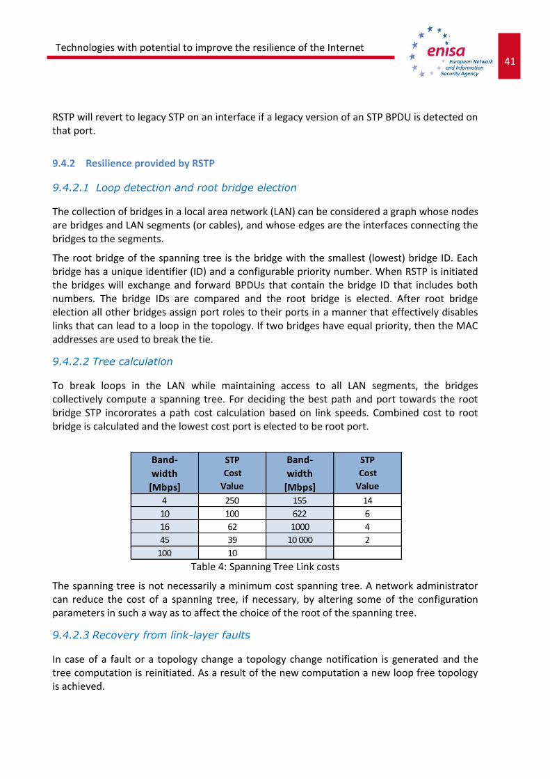
41 Technologies with potential to improve the resilience of the Internet
infrastructure
RSTP will revert to legacy STP on an interface if a legacy version of an STP BPDU is detected on that port.
9.4.2 Resilience provided by RSTP
9.4.2.1 Loop detection and root bridge election
The collection of bridges in a local area network (LAN) can be considered a graph whose nodes are bridges and LAN segments (or cables), and whose edges are the interfaces connecting the bridges to the segments.
The root bridge of the spanning tree is the bridge with the smallest (lowest) bridge ID. Each bridge has a unique identifier (ID) and a configurable priority number. When RSTP is initiated the bridges will exchange and forward BPDUs that contain the bridge ID that includes both numbers. The bridge IDs are compared and the root bridge is elected. After root bridge election all other bridges assign port roles to their ports in a manner that effectively disables links that can lead to a loop in the topology. If two bridges have equal priority, then the MAC addresses are used to break the tie.
9.4.2.2 Tree calculation
To break loops in the LAN while maintaining access to all LAN segments, the bridges collectively compute a spanning tree. For deciding the best path and port towards the root bridge STP incororates a path cost calculation based on link speeds. Combined cost to root bridge is calculated and the lowest cost port is elected to be root port.
Table 4: Spanning Tree Link costs
The spanning tree is not necessarily a minimum cost spanning tree. A network administrator can reduce the cost of a spanning tree, if necessary, by altering some of the configuration parameters in such a way as to affect the choice of the root of the spanning tree.
9.4.2.3 Recovery from link-layer faults
In case of a fault or a topology change a topology change notification is generated and the tree computation is reinitiated. As a result of the new computation a new loop free topology is achieved.
Band-
width
[Mbps]
STP
Cost
Value
Band-
width
[Mbps]
STP
Cost
Value
4 250 155 14
10 100 622 6
16 62 1000 4
45 39 10 000 2
100 10

42 Technologies with potential to improve the resilience of the Internet infrastructure
9.4.2.4 RSTP Performance
When evaluating and tuning RSTP in a switched network different timers are essential. The most important timer is the Hello time (default 2 seconds on Cisco switches), which defines the interval for sending BPDUs. While STP can take 30 to 50 seconds to respond to a topology change, RSTP is typically able to respond to changes within 3 × Hello time (default: 6 seconds) or within a few milliseconds of a physical link failure.
9.4.3 RSTP Security
9.4.3.1 Root bridge protection
The standard STP does not provide any means for the network administrator to securely enforce the topology of the switched network. A means to enforce topology can be especially important in networks with shared administrative control, where different administrative entities or companies control one switched network.
The forwarding topology of the switched network is calculated as seen in previous chapters. Calculation is based on the root bridge position, among other parameters. Any switch can be the root bridge in a network. But a more optimal forwarding topology places the root bridge at a specific predetermined location. With the standard STP, any bridge in the network with a lower bridge ID takes the role of the root bridge. The administrator cannot enforce the position of the root bridge.
A root port elected through this process has the possibility of being wrongly elected. A user bridge application running on a PC can generate BPDUs, too, and interfere with root port election. Root protection allows network administrators to manually enforce the root bridge placement in the network.
All major network equipment vendors have implemented methods and configurations to enforce the root bridge position in the network.
9.4.4 Challenges in RSTP implementation
9.4.4.1 Sub-optimal paths in multiple VLANs
RSTP doesn't natively separate between VLANs, which leads to all VLANs using the same spanning tree topology. In this situation it would be preferred to separate different VLANs to different root bridges.
All vendors have implemented such Rapid Spanning tree feature.
9.4.4.2 Performance with multiple adjacent links and paths
Any loop is prevented with disabling ports form forwarding traffic, which causes only one link to be active at any given time between adjacent bridges. This obviously is a performance issue

43 Technologies with potential to improve the resilience of the Internet
infrastructure
and all the installed bandwidth cannot be utilized. Especially this affect corporate core networks and datacentres and multiple different technologies have been developed to circumvent the throttling caused by spanning tree protocol.
9.4.4.3 Challenges in large networks with constant topology change notifications
(TCN)
The more hosts are in the network, the higher are the probabilities of getting a topology change. For instance, a directly attached host triggers a topology change when it is power cycled. In very large (and flat) networks, a point can be reached where the network is perpetually in a topology change status.
I bad quality cable or port can also cause constant triggering of TCNs and destabilize the whole network.
9.4.5 Deployment
9.4.5.1 Current status
Very commonly deployed in corporate and datacentre networks and all layer 2 switched networks. Spanning Tree protocol does not propagate between broadcast domains or LANs which limits its usage to internal switched networks and Internet switches.
9.4.5.2 Future deployment status
There is a number of activities aimed at the replacement to RSTP mainly because of performance issues and decrease in bandwidth when implementing spanning tree.
Main contestants for an alternate method to prevent switching loops are
Transparent Interconnect of Lots of Links (TRILL)
Uses IS-IS routing protocol on layer 2 to ensure loop free topology
Shortest Path Bridging (SPB)
uses a link state protocol to advertise both topology and logical network
membership
Ethernet Ring Protection Switching (ERPS)
ITU-T under G.8032 Recommendation to provide sub-50ms protection and
recovery switching for Ethernet traffic in a ring topology
Resilient Packet Ring (RPR)
is a standard designed for the optimized transport of data traffic over optical fiber
ring networks.

44 Technologies with potential to improve the resilience of the Internet infrastructure
Ethernet Automatic Protection Switching (EAPS)
Extreme Networks’ solution for fault-tolerant Layer 2 ring topologies.
Resilient Ethernet Protocol (REP)
Cisco proprietary protocol that provides an faster alternative to Spanning Tree
Protocol (STP)
9.4.6 Survey results
RSTP was found to be the most commonly implemented loop prevention technology along with its more or less similar sister technologies MSTP and STP. Clearly loop prevention and layer 2 optimization it still very actively implemented technology and only recently there has been more effort to develop and implement a more robust and efficient technologies for switching domain optimization.
9.4.6.1 Deployed LAN resilience technologies
The respondent’s organizations LAN resilience technologies were concentrated on layer 2 loop prevention protocols with the exception of LACP and Cisco specific VSS which are not specifically loop prevention technologies but are used for efficient usage of bandwidth and minimizing the dependence and overhead of spanning tree.
Spanning Tree technologies are getting old and their aging is clearly showing throughout organizations. Most of the respondents have identified the notable drawbacks of spanning tree and have implemented or actively seeking replacement protocols or technologies to minimize the usage of spanning tree. The improvement of layer 2 resilience has been seen to be twofold process. On one hand the protocol to replace STP related protocols are studied and evaluated and on the other hand technologies to minimize the need for spanning tree are being implemented.
Among the deployed protocols for layer 2 resilience are TRILL (transparent interconnect of lots of links), SPB (shortest path bridging) and RPR (resilient packet ring). These protocols are showing promise in improving the resilience but are still marginal in usage when compared to spanning tree protocols and the competition to become the major technology is still very much on-going.
There's a considerable effort also being put to minimize the need for spanning tree and similar protocols altogether and the technologies for this are being developed actively. Standard implementation is to combine adjacent links to groups and handle the group of links as one link on spanning tree domain. Grouping of the links is implemented multiple of ways LACP (link aggregation control protocol) being the standard protocol to automate channelling of links. Recently vendors have introduced technologies to group non-adjacent elements and these technologies are also actively being looked into, specifically Cisco VSS has been implemented within the respondent’s organization to minimize the STP performance hit.

45 Technologies with potential to improve the resilience of the Internet
infrastructure
ERPS, EAPS or REP was not among the implemented layer 2 resilience technologies according this survey. This is likely due to these technologies being relatively new and targeted for a specific environment and not widely known. EAPS is also Extreme Networks proprietary and none of the respondent’s organization had deployed their switching technologies which prevents the EAPS implementation.
RSTP deployments in LANs were mostly spanning the whole switched network and not limited to access or core devices. This is very common and usually does not reflect the need or desire to deploy spanning tree but spanning tree is left running on the switches even without loops on the network as a precautionary measure. Spanning tree domains are naturally minimized using layer 3 devices and subnetting.
Figure 13: Layer 2 resilience technologies
9.4.6.2 Drawbacks of RSTP
As previously mentioned, RSTP is getting old and even though it has been the best loop prevention technology for years, its showing age and relative slowness has also been observed in the organizations in the survey.
Monitoring and management of the RSTP domain, topology changes and tree recalculations has been found difficult and collecting data about RSTP performance is difficult. Better tools for centrally managing and monitoring are needed to utilize spanning tree protocols in an optimized way and to prevent spanning tree from blocking links in a suboptimal way considering the networks topology. Multivendor environments bring also challenges with multiple management interfaces.

46 Technologies with potential to improve the resilience of the Internet infrastructure
Spanning tree has been found to be error prone and a bug on the spanning tree software or a misconfiguration can cause serious performance hits on the switched network or even prevent the network service altogether causing breaks in the service. Also the impact of topology change, either planned or unplanned, has been found to cause a longer break in the service then would be desirable and slow convergence particularly in larger switched networks has been seen as a significant drawback.
Multiple respondents have experienced problems in RSTP multivendor environments and interoperability has been an issue. Vendor extensions to the underlying protocols have caused unpredictable errors in the networks and the root cause of the problem is often really difficult to find since these errors cannot be seen in the configuration.
A clear observed drawback inherent to the spanning tree structure is the impact on the performance on the network. Physical bandwidth as not utilized fully when implementing spanning tree since the whole purpose of the protocol is to block links causing the loops in the network.
9.4.6.3 Testing of fault tolerance
RSTP was tested regularly in majority of networks via shutting down redundant links and observing the topology change and the recovery of the network. Testing topology changes in service provider environment is challenging since RSTP topology change typically causes service breaks in the logical network.
9.4.6.4 Incidents because of RSTP
Multiple incidents in the networks had occurred in RSTP implementations. Incidents were found to be caused or likely to be caused by problems in RSTP protocol. Only in one respondents organization the incident was identified to be due to an RSTP misconfiguration.
9.4.6.5 Network design principles
Most of the responses reflect a desire to minimize the usage of RSTP altogether or a desire to replace RSTP, mostly because of before mentioned problems with interoperability, performance and challenges in management and monitoring in the protocol implementation.
9.4.6.6 Replacement of RSTP
The plans to minimize and/or replace RSTP with another method to prevent loops in the data link layer seem to concentrate on three prominent technologies: 1 MPLS and IP implementation to rid the network of layer 2 resilience technologies
altogether
2 TRILL, ERPS, RPR or some other protocol to replace RSTP as a layer 2 loop prevention
protocol

47 Technologies with potential to improve the resilience of the Internet
infrastructure
3 Etherchannel automated with LACP or VSS to logically group links and in this manner to
prevent RSTP from blocking redundant links.
9.4.7 Summary
Rapid Spanning tree is, despite its shortcomings, still a very commonly used protocol. Its future is clearly shortening and viable replacement protocols are being developed and deployed in corporate and datacentre networks.
9.5 Fibre Channel
9.5.1 Overview of Fibre Channel
Fibre Channel, or FC, is a gigabit-speed network technology primarily used for storage networking and transports SCSI commands on top of network infrastructure. Fibre Channel is standardized in the T11 Technical Committee of the Inter National Committee for Information Technology Standards (INCITS), an American National Standards Institute (ANSI)–accredited standards committee. Fibre Channel was primarily used in the supercomputer field, but now, has become the standard connection type for storage area networks (SAN) in enterprise storage. Despite its name, Fibre Channel signalling can run on both twisted pair copper wire and fibre-optic cables.
Fibre Channel does not follow the OSI model layering, but is split similarly into 5 layers, namely:
FC4 — Protocol Mapping layer, in which application protocols, such as SCSI or IP, are encapsulated into a PDU for delivery to FC2.
FC3 — Common Services layer, a thin layer that could eventually implement functions like encryption or RAID redundancy algorithms;
FC2 — Network layer, defined by the FC-PI-2 standard, consists of the core of Fibre Channel, and defines the main protocols;
FC1 — Data Link layer, which implements line coding of signals;
FC0 — PHY, includes cabling, connectors etc.;
Layers FC0 through FC2 are also known as FC-PH, the physical layers of Fibre Channel.
Fibre Channel routers operate up to FC4 level (i.e. they may operate as SCSI routers), switches up to FC2, and hubs on FC0 only.
Fibre Channel products are available at 1, 2, 4, 8, 10, 16, 20, 32 and 40 Gbit/s; these protocol flavours are called accordingly 1GFC, 2GFC, 4GFC, 8GFC, 10GFC, 16GFC, 20GFC, 32GFC, and 40 GFC. The 16GFC and 40 GFC standard was approved by the INCITS T11 committee in 2010 and 2011 , and those products are expected to become available in 2011. Products based on the 1GFC, 2GFC, 4GFC, 8GFC and 16GFC standards should be interoperable and backward

48 Technologies with potential to improve the resilience of the Internet infrastructure
compatible. The 1GFC, 2GFC, 4GFC, 8GFC designs all use 8b/10b encoding, while the 16GFC standard uses 64b/66b encoding. Unlike the 10GFC and 20GFC standards, 16GFC provides backward compatibility with 4GFC and 8GFC.
Fibre Channel specifies three connection types: FC-Base2, FC-Base10 and FC-BaseT. All speeds of Fibre Channel – 1, 2 and 4 – are backward compatible for two previous generations. FC-Base2 is the predominant Fibre Channel interconnects used for fabric edge implementations and interswitch links. FC-Base10 is used for interswitch links and FC-BaseT is used to plug Fibre Channel into twisted pair Ethernet installations. FC-BaseT has the same physical connectors and cables as Ethernet.
Table 5: FC Standard statuses for FC-base2 and FC-base10 Fibre Channels
The 10 Gbit/s standard and its 20 Gbit/s derivative, however, are not backward compatible with any of the slower speed devices, as they differ considerably on FC1 level in using 64b/66b encoding instead of 8b/10b encoding, and are primarily used as inter-switch links.
9.5.1.1 About FC protocol
Fibre Channel Protocol (FCP) is a transport protocol (similar to TCP used in IP networks) which predominantly transports SCSI commands over Fibre Channel networks.
9.5.1.2 FC Architecture
There are three major Fibre Channel topologies, describing how a number of ports are connected together. A port in Fibre Channel terminology is any entity that actively communicates over the network, not necessarily a hardware port. This port is usually
FC-Base2 Mbytes/s T11 Spec
Completed
Market Availability
1GFC 100 1996 1997
2GFC 200 2000 2001
4GFC 400 2003 2005
8GFC 800 2006 2008
16GFC 1600 2009 2011
32GFC 3200 2012 Market demand
64GFC 6400 2016 Market demand
128GFC 12800 2020 Market demand
FC-Base10 Mbytes/s T11 Spec Market Availability
10GFC 1200 2003 2004
20GFC 2400 2008 2008
40GFC 4800 2009 2011
80GFC 9600 Future Market demand
100GFC 12000 Future Market demand
160GFC 19200 future Market demand

49 Technologies with potential to improve the resilience of the Internet
infrastructure
implemented in a device such as disk storage, an HBA on a server or a Fibre Channel switch.[1]
Point-to-Point (FC-P2P). Two devices are connected directly to each other. This is the simplest topology, with limited connectivity.
Arbitrated loop (FC-AL). In this design, all devices are in a loop or ring, similar to token ring networking. Adding or removing a device from the loop causes all activity on the loop to be interrupted. The failure of one device causes a break in the ring. Fibre Channel hubs exist to connect multiple devices together and may bypass failed ports. A loop may also be made by cabling each port to the next in a ring.
A minimal loop containing only two ports, while appearing to be similar to FC-P2P, differs considerably in terms of the protocol.
Only one pair of ports can communicate concurrently on a loop.
Maximum speed of 8GFC.
Switched fabric (FC-SW). All devices or loops of devices are connected to Fibre Channel switches, similar conceptually to modern Ethernet implementations. Advantages of this topology over FC-P2P or FC-AL include:
The switches manage the state of the fabric, providing optimized interconnections.
The traffic between two ports flows through the switches only; it is not transmitted to any other port.
Failure of a port is isolated and should not affect operation of other ports.
Multiple pairs of ports may communicate simultaneously in a fabric.
Fibre Channel uses a shorthand terminology to describe different types of connections to the Fibre Channel network. Fibre Channel uses the term “ports” and defines seven different types of ports:
N-port: Network Port - port used to connect a node to a Fibre Channel switch
F-port: Fabric Port - Switch port used to connect the Fibre Channel fabric to a node
L-port: Loop Port - Node port used to connect a node to a Fibre Channel loop
NL-port: Network + Loop Port - Node port which connects to both loops and switches
FL-port: Fabric + Loop Port - Switch port which connects to both loops and switches
E-port: Extender Port - Used to cascade Fibre Channel switches together
G-port: General Port - General purpose port which can be configured to emulate other port types
9.5.2 Resilience provided by FC
Previously mentioned Point-to-Point (FC-P2P) and Arbitrated loop (FC-AL) are not optimal in

50 Technologies with potential to improve the resilience of the Internet infrastructure
redundancy and resilience since and in reality all resilient architectures are built on Switched fabric (FC-SW) architecture.
9.5.2.1 Switched fabric
Devices are connected to each other through one or more Fibre Channel switches. This topology allows the connection of up to the theoretical maximum of 16 million devices, limited only by the available address space (224). Multiple switches in a fabric usually form a mesh network, with devices being on the "edges" ("leaves") of the mesh. While this topology has the best scalability properties of the three FC topologies, it is also the most expensive, the only one requiring a costly Fibre Channel switch.
Figure 14: Switched fabric
Visibility among nodes in a fabric is typically controlled with zoning.
Most Fibre Channel network designs employ two separate fabrics for redundancy. The two fabrics share the edge nodes (devices), but are otherwise unconnected. One of the advantages of this topology is capability of failover, meaning that in case one link breaks or a switch is out of order, datagrams can use the second fabric.
9.5.2.2 FC Multipathing
On redundant switching fabric architecture the storage devices are accessible to nodes via multiple paths. The datagrams for transporting SCSI can pick from multiple routes which in

51 Technologies with potential to improve the resilience of the Internet
infrastructure
turn means that the devices should be able to decide and control which route is taken.
Figure 15: FC Multipath
9.5.3 FC Security
FC security concentrates on authentication of FC datagrams and in special scenarios encrypting the FC payload.
9.5.3.1 FCAP (Fibre Channel Authentication Protocol)
FCAP is an optional authentication mechanism employed between any two devices or entities on a Fibre Channel network using certificates or optional keys.
9.5.3.2 FCPAP (Fibre Channel Password Authentication Protocol)
FCPAP is an optional password based authentication and key exchange protocol which is utilized in Fibre Channel Storage Area Networks (SAN’s).
FCPAP is used to mutually authenticate Fibre Channel ports to each other. This includes E_Port’s, N_Port’s, and Domain Controllers.
9.5.3.3 ESP over Fibre Channel
ESP (Encapsulating Security Payload) is a Internet standard for the authentication and encryption of IP packets. ESP is defined in RFC 2406: IP Encapsulating Security Payload (ESP). ESP is widely deployed in IP networks and has been adapted for use in Fibre Channel networks. The IETF iSCSI proposal specifies ESP link authentication and optional encryption.
ESP over Fibre Channel is focused on protecting data in transit throughout the Fibre Channel network. ESP over Fibre Channel does not address the security of data which is stored on the Fibre Channel network.
9.5.3.4 FC-SP (Fibre Channel – Security Protocol)
Fibre Channel – Security Protocol (FC-SP) is a security protocol for Fibre Channel Protocol (FCP) and fiber connectivity (Ficon). FC-SP is a project of Technical Committee T11 of the InterNational Committee for Information Technology Standards (INCITS).
FC-SP is a security framework which includes protocols to enhance Fibre Channel security in several areas, including authentication of Fibre Channel devices, cryptographically secure key

52 Technologies with potential to improve the resilience of the Internet infrastructure
exchange, and cryptographically secure communication between Fibre Channel devices.
FC-SP is focused on protecting data in transit throughout the Fibre Channel network. FC-SP does not address the security of data which is stored on the Fibre Channel network.
ESP is widely deployed in IP networks and has been adapted for use in Fibre Channel networks. The IETF iSCSI proposal specifies ESP link authentication and optional encryption.
ESP over Fibre Channel is focused on protecting data in transit throughout the Fibre Channel network. ESP over Fibre Channel does not address the security of data which is stored on the Fibre Channel network.
9.5.3.5 SLAP (Switch Link Authentication Protocol)
SLAP is an authentication method for Fibre Channel switches which utilizes digital certificates to authenticate switch ports. SLAP was designed to prevent the unauthorized addition of switches into a Fibre Channel network.
9.5.3.6 Attacks against FCP
Attacks against FCP (Fibre Channel Protocol) include:
Node Name / Port Name spoofing at Port Login time
Source Port ID spoofing on data-less FCP commands
Snooping and spoofing on FC-AL
Snooping and Spoofing after Fabric reconfiguration
Denial of Service attacks can be made in User mode
9.5.4 Deployment
9.5.4.1 Current status
Mostly all corporate, governmental and operator datacentre and server facilities implement Fibre Channel storage in one form or another despite FC architecture costs being relatively high in larger environments.
Fibre Channel is also extended to suit more specific needs based on budget as well as speed and distance. Extensions include: Fibre Channel over IP (FCIP) is an important technology for linking Fibre Channel storage
area networks (SAN). FCIP is a complementary solution for enabling company wide access
to storage. FCIP transparently interconnects Fibre Channel (FC) SAN islands over IP
networks.
Fibre Channel over Ethernet (FCoE) is an encapsulation of Fibre Channel frames over
Ethernet networks. This allows Fibre Channel to use 10 Gigabit Ethernet networks (or

53 Technologies with potential to improve the resilience of the Internet
infrastructure
higher speeds) while preserving the Fibre Channel protocol. The specification, supported
by a large number of network and storage vendors, is part of the International Committee
for Information Technology Standards T11 FC-BB-5 standard.
9.5.4.2 Future deployment status
There is no clear competition for Fibre Channel and current efforts in SAN storage area concentrate on higher speeds. Also considerable effort is being put to deploy FC over Ethernet architecture which simply put transports FC datagrams over existing or another Ethernet architecture. Main benefit for FC over Ethernet is lower cost of Ethernet compared to FC hardware. 9.5.5 Survey results
1G Ethernet, 10G Ethernet and Fibre Channel are most commonly deployed storage access technologies. Fibre channel is a clear choice for storage network and presents no surprises in deployments. Ethernet technologies for storage access on the other hand are a bit of a strange nomination for storage access especially since FC over Ethernet was not named to be deployed.
9.5.5.1 Deployed storage access technologies
The top three storage access technologies are 10GE, 1GE and Fibre Channel. iSCSI is also very close contestant on the most implement technologies.

54 Technologies with potential to improve the resilience of the Internet infrastructure
Figure 16: Storage Access technologies
These responses indicate a possible inconsistency on the form or the respondents understanding of the storage access. From the survey one might actually draw a conclusion that the responses are a combination of two or more technologies.
- Fibre Channel over 10G or 1G Ethernet
- iSCSI on 10G or 1G Ethernet and IP network
- Network attached storage technologies, such as NFS or CIFS
Responding Ethernet as a storage access might also imply the usage of a vendor specific unified fabric solution that supports the convergence of data traffic and storage traffic to a unified access solution. The reason for this perceived inconsistency cannot be confirmed from the survey results.
Background information on Fibre Channel indicates that it is a dominant technology for storage access in datacentres and survey confirms this with the exception of listing the Ethernet technologies to storage access. Using either Ethernet of Fibre Channel stack for storage access is common and standards supported and the resilience features including dual fabric and virtualization support are thoroughly tested hence no respondents indicated using some other form of storage access technologies.

55 Technologies with potential to improve the resilience of the Internet
infrastructure
9.5.5.2 Deployed Fibre Channel topologies
Fibre channel is most commonly implemented as a switched fabric which means that the full features of Fibre Channel switches and zoning are available to support in enhancing the resilience of deployed Fibre Channel Storage Area Networks. This result was expected since the other topologies for Fibre Channel (FC-P2P and FC-AL) are not inherently redundant or resilient.
FC-P2P was also deployed in respondents storage, and using FC-P2P is very efficient in a specific environment were the storage access is very limited geographically and logically and the storage access is not critical for the service provided with the particular server or servers such as high performance clusters or certain support functions in the data centre.
9.5.6 Summary
Fibre Channel is robust, widely implemented and reliable protocol stack and SAN architecture that has currently no real competition. SAN architecture resilience is a key element in current Internetworking services being usable and accessible even when is has no direct link in Internetworking.
10 Supply Chain Integrity and Network Resilience
10.1 Introduction to supply chain integrity in telecom industry
Supply chain integrity in the ICT industry is an important topic that is receiving attention from both the public and private sectors (i.e. vendors, infrastructure owners, operators, etc). Supply chains of many telecommunications operators have changed a lot in recent years. Many traditional telecommunications operators and suppliers are increasingly relying on off-shore component sourcing and new suppliers have taken significant actions to position themselves to be major suppliers to many telecommunication operators in Europe and North America. Operators have also outsourced significant parts of their operations (i.e. installations, building of infrastructure, network management, etc) to third parties which operate globally. Virtually any part of the life cycle of device, system, network, and IT service may be outsourced to different suppliers and subcontractors.
Integrity as a concept is related to perceived consistency of actions, values, methods, measures, principles, expectations and outcome. People use integrity as a holistic concept, judging the integrity of systems in terms of those systems’ ability to achieve their own goals (if any). Integrity, thus, is an essential element of security. The meaning of integrity can change considerably depending on the context of its use. In the context of information security, integrity means that the data has not been altered in an unauthorized manner, degraded or compromised. Within the software context, SAFECode defines integrity as ensuring that the process for sourcing, creating and delivering software contains controls to enhance
56 Technologies with potential to improve the resilience of the Internet infrastructure
confidence that the software functions as the supplier intended. In ICT in general, integrity is a complex notion linked to the concepts of security assurance and trust (we trust systems when they behave and perform in the expected manner). In the end, the goal is to provide ICT products that meet the original and/or agreed upon specifications.
A telecommunications service involves people and processes in addition to technology. This is also reflected in supply chains. Product oriented supply chains may consist of software and hardware design, testing, production, delivery, repair, support, and maintenance. Supply chains related to telecommunications services include network design, testing, installation, network management, and other processes related to IT service production as defined e.g. by ITIL. In the studies of supply chain integrity the focus is in the product oriented supply chains and therefore this report is handling the supply chain integrity from that point of view.
10.2 Case study: Cyber Security Evaluation Centre
One example of supply chain integrity assessment is Cyber Security Evaluation Centre (CSEC) in the United Kingdom. The Cyber Security Evaluation Centre has been established as a joint initiative with the UK government to perform detailed security testing and to interface with the supplier’s development and maintenance facilities and provide assessment results to appropriate stakeholders. The Cyber Security Evaluation Centre is owned and operated by Huawei. The main customers of this centre are telecom operators and national security authorities.
In the Cyber Security Evaluation Centre the operators and national security authorities can perform detailed tests and analysis to ensure the supply chain integrity of the products. The test plan is done for every case with the customer. The tests includes for example: Hardware test
Complete analysis of the hardware
Analysis of the source and function of every hardware component of the equipment
Scanning of firmware for vulnerabilities, e.g. buffer analysis
Software test
Audit of source code, e.g. by statistical scanning and review
Source code is compiled into working binaries
Compiled code is compared with original binary code and the same origin is verified.
Both binaries are scanned, and potential vulnerabilities in both of them are searched
and compared
Ethical hacking
Penetration testing of all the binaries and hardware
Hacking of both the software and hardware
A typical project lasts 3-4 months depending on complexity and normally there are 20-40 people involved in a project from the stakeholders (testing centre, client, vendor, authorities). Every project to test and analyse the supply chain integrity of equipment is a big investment

57 Technologies with potential to improve the resilience of the Internet
infrastructure
and consumes considerable amount of time. The tests in the project give a fairly reliable snapshot of the supply chain integrity with certain product with a certain hardware and software version. With the new versions and updates of the product in principle also the assessment should be updated.
10.3 Study results: managing supply chain integrity risks in Europe
In this study the questionnaire including questions of supply chain integrity was sent to several telecom equipment suppliers, telecom operators, regulators and government security authorities. Added to this about ten people were especially interviewed related to supply chain integrity issues. Generally the summary of the questions and interviews is:
Awareness of supply chain integrity: Supply chain integrity is known as a basic concept to most of the respondents, but at a deeper level it was fairly unknown.
Standards or good practices related to the supply chain integrity: Standards or practices related specifically to supply chain integrity are usually rarely implemented. When they existed, they were rather based on traditional security or procurement frameworks than focusing on the supply chain itself. Some of the respondents try to control the supply chain by agreeing with the supplier directly. The telecom equipment suppliers are willing to implement supply chain integrity auditing methods to their processes, e.g. vendor audits are in use. In the other groups assessing supply chains was minimal. There are some methods and practices used to audit and test the telecom equipment (like in CSEC) but they are complex and time consuming.
Internal/external regulation (liability, export control, privacy) of HW/SW: Most of respondents informed, that procurement of new HW/SW is subject to internal or external regulations, such as procurement laws (public sector), ISO 27001/2 security standards and internal security testing procedures were also mentioned. Only in one operator organization has tests of security features of the hardware and software before acceptance. One governmental organization performs risk analysis to the parts of the system.
Metrics related to the supply chain: No supply chain integrity specific metrics are used in supply chains among respondents. Otherwise supply chains are measured in traditional metrics, e.g. service level agreements (SLA) in service oriented supply chains. In fact the SLA levels were the only mentioned metrics related to supply chain.
Risks on telecom network implementation: The people who were interviewed pointed out that besides the product supply chain integrity it is even more important to assure the integrity of the service chain. From the network resilience point of view the priorities of supply chain integrity are:
1. Network management and maintenance
2. Network implementation
3. Network design
4. Network products
58 Technologies with potential to improve the resilience of the Internet infrastructure
In general it was agreed that problems in supply chain integrity may have a big impact on the resilience of telecommunications networks. It was a common understanding in the interviews that service oriented supply chains (network management and maintenance, implementation) were more critical factor to resilience than product oriented (hardware/software) supply chains.
Sharing of supply chains: The suppliers in their products or services often have components, which are shared by several clients. The same components are used in network devices. Especially in low end devices the core chip sets are produced only by a handful of vendors. The software may be also shared: in many embedded devices there is Linux or FreeBSD running in the core. Protocol stacks are also merchandise and often share by several vendors. A zero day vulnerability in these core hardware or software components affects a large number of products from different vendors. The similar situation is on the service supply chain. The same service company may be supplier to several operators. A security problem in the processes or personnel of this supplier affects a large group of operators, in the worst case all the major player in a certain country.
10.4 Recommendations
Assessment of supply chain integrity is uncommon with exception of certain vendors. The concept is fairly new, its importance is not fully recognized, there are different views of its focus (product vs. service) and good practices have not been developed for it. There are a number of national and international frameworks, guidelines, best practices, models etc. for security assessments of products and services. These however, do no address supply chains specifically. It is recommended to build a framework and guidelines for supply chain assessment at EU level.
If this guideline recommends product or supplier audits, these should be also audited at EU level. In this way the expensive and laborious audit could be used in several occasions in several countries.
59 Technologies with potential to improve the resilience of the Internet
infrastructure
Annex 1: Questionnaire
Introduction Contact person:
Email:
Phone:
Country:
Organization:
Type of organization
Internet operator
Telecom (fixed and mobile) operator
Enterprise
Research institute or university
Standards body (e.g. IETF, IEEE, ETSI, etc.)
Public sector
National security unit, e.g. defence, cyber war unit, national CERT , etc.
IT Service organization
In how many countries do you have offices?
My name can be printed in the report as interviewee Yes/No
RSTP (Rapid Spanning Tree)
Which LAN/MAN protection/resilience technologies are deployed in your networks STP Spanning Tree
RSTP Rapid Spanning Tree
MSTP Multiple Spanning Tree
TRILL Transparent Interconnect of Lots of Links
SPB Shortest Path Bridging
ERPS "Ethernet Ring Protection Switching "
RPR Resilient Packet Ring
EAPS Ethernet Automatic Protection Switching
REP Resilient Ethernet Protocol
LACP Link Aggregation Control Protocol
InfiniBand
Other, please specify

60 Technologies with potential to improve the resilience of the Internet infrastructure
Choices: Deployed - Plan to deploy – No plans – No knowledge of deployment – Have not heard about the technology
If RST is deployed, is it Used in all the switches
Used in core switches
Used in LAN
Used in MAN/Access network
Used as little as possible
What is the most severe drawback of RSTP as a technology?
Is the fault tolerance of RSTP tested in practice in new networks?
Have you had incidents in your network because of RSTP?
Have you designed the network in order to minimize usage of RSTP?
What is the most promising replacement technology to RSTP?
FC (Fibre Channel)
Which of the following technologies are in use in your data centre(s) to access storage devices? Fibre Channel
Fibre Channel over Ethernet
Fibre Channel over SONET/SDH
Fibre Channel over IP
iSCSI
ATA over Ethernet
Gigabit Ethernet
Gigabit Ethernet
40Gigabit Ethernet
100Gigabit Ethernet
What topology do you use in your fibre channel implementations? Point-to-Point (FC-P2P): Two devices are connected directly to each other.
Arbitrated loop (FC-AL): All devices are in a loop or ring, similar to token ring
networking.
Switched fabric (FC-SW): All devices or loops of devices are connected to Fibre
Channel switches

61 Technologies with potential to improve the resilience of the Internet
infrastructure
FC (IS-IS)
What is your preferred Intra-AS routing protocol? IS-IS
OSPF
RIPv1&2
EIGRP
What do you consider to be the most important aspect of Intra-AS routing protocol? Rapid convergence
Support for load balancing between multiple paths
Ease of implementation
Support for hierarchical routing architecture
Security features like authentication and encryption
Other, please specify
If you use IS-IS, have you had any issues or drawbacks inherent to the protocol?
How do you test the convergence of the routing protocol?
Do you follow or monitor the interior routing protocol in your implementations?
Do you consider the choice of interior routing protocol to be an important aspect to
enhance resilience?
Where do you have interior routing protocol implemented? datacentre network
backbone network
Access or corporate networks
FC (VRRP)
How do you handle the first hop redundancy in your networks? HSRP
VRRP
GLBP
Other, please specify
What do you consider to be the most important aspect of first hop redundancy protocol?

62 Technologies with potential to improve the resilience of the Internet infrastructure
fast fall-back
support for load balancing
ease of implementation
support for real IP-addresses
security features like authentication and encryption
other, please specify
If you use VRRP, have you had any issues or drawbacks inherent to the protocol?
How do you test the resilience of the first hop redundancy protocol?
Do you follow or monitor the protocol in your implementations? If you do, how?
Do you consider the choice of first hop redundancy protocol to be an important
aspect to enhance resilience?
Where do you have firs hop redundancy protocol implemented? Datacentre network
Backbone network
Access or corporate networks
Other technologies
Are you using (or planning to introduce) one of the below-mentioned technologies? MPLS
DNSSEC
IPv6
S-BGP
Supply Chain Integrity Is the concept of supply chain integrity (verification of genuity and quality of
procured HW and SW) known to you?
Does your company use any standards or good practices related to the supply chain
integrity?
Is the procurement of new HW/SW subject to internal/external regulations (liability,
export control, privacy)?
Do you have any means of assessing the resilience of your supply chain?
Do you use any metrics in relation to the supply chain?

63 Technologies with potential to improve the resilience of the Internet
infrastructure
Annex 2: Persons participated in the survey
Only those names printed that have given permission
Name Organization Title/description
Heikki Almay NSN Packet Networks Head of R&D Partnering, Packet Networks
Yrjö Benson Ministry of Defence, Finland Director, Security and Defence Committee
Rob Evans Janet Senior Technical Specialist
Anne-Marie Eklund Lowinder IIS Quality and Security Manager
John Frieslaar Huawei Cyber Security
Evaluation CentreManaging director
Pertti Hölttä FICORA Head of Communications Networks
Athanasios Liakopoulos GRNET
Kurt Erik Lindqvist NetNod CEO
Jared Mauch NTT America IP Engineer
Jorma Mellin TDC/FICIX CTO of TDC, Chairman of FICIX
Klaus Nieminen FICORA Senior Adviser
Arnold Nipper De-Cix CTO/COO
Kari OjalaMinistry of Traffic
and CommunicationsSenior Advisor, Communications Counsellor
Nuno Vieira NFsi Telecomm CTO
Achilles P. VoliotisOTEnet SA Internet
Service Provider Network Planning & Development Manager

2 Technologies with potential to improve the resilience of the Internet infrastructure
P.O. Box 1309, 71001 Heraklion, Greece www.enisa.europa.eu