temperature regulation solution - omron · 6 | temperature regulation solution quick start guide...
TRANSCRIPT
Temperature Regulation Solution
Quick Start Guide
Version v1.02 OMRON Europe
industrial.omron.eu

2 | Temperature Regulation Solution
Quick Start Guide v1.02
Contents
ABBREVIATIONS .......................................................................................................................................................... 3
EXECUTIVE SUMMARY ................................................................................................................................................ 4
INTENDED AUDIENCE .................................................................................................................................................. 5
PID CONTROL ALGORITHMS ........................................................................................................................................ 6
PID CONTROL ALGORITHM .................................................................................................................................................... 6 2-PID CONTROL ALGORITHM ................................................................................................................................................. 8
1 ON-PANEL TEMPERATURE REGULATION............................................................................................................ 12
1.1 INTRODUCTION ...................................................................................................................................................... 12 1.2 SYSTEM CONFIGURATION......................................................................................................................................... 13 1.3 WIRING DIAGRAMS ................................................................................................................................................ 14 1.4 COMMUNICATION SETTINGS .................................................................................................................................... 18 1.5 MODBUS RTU PROTOCOL ....................................................................................................................................... 24
2 IN-PANEL TEMPERATURE REGULATION ............................................................................................................. 28
2.1 INTRODUCTION ...................................................................................................................................................... 28 2.2 PROGRAMLESS COMMUNICATION ............................................................................................................................. 29 2.3 SYSTEM CONFIGURATION......................................................................................................................................... 31 2.4 WIRING DIAGRAMS ................................................................................................................................................ 35 2.5 COMMUNICATION SETTINGS .................................................................................................................................... 41
3 IN-PANEL INTEGRATED TEMPERATURE REGULATION ........................................................................................ 50
3.1 INTRODUCTION ...................................................................................................................................................... 50 3.2 TEMPERATURE CONTROL 2-PID FUNCTION BLOCK ....................................................................................................... 51 3.3 SYSTEM CONFIGURATION......................................................................................................................................... 60 3.4 COMMUNICATION SETTINGS .................................................................................................................................... 63
REFERENCES .............................................................................................................................................................. 69
APPENDIX.................................................................................................................................................................. 70
APPENDIX A: E5_C HARDWARE INFORMATION ....................................................................................................................... 71 APPENDIX B: E5_C COMMUNICATION PARAMETER SETUP ........................................................................................................ 75

Temperature Regulation Solution | 3
Quick Start Guide v1.02
ABBREVIATIONS
PLC Programmable Logic Controller HMI Human Machine Interface TC Temperature Controller SSR Solid State Relay FB Function Block PV Process Value SP Set Point P Proportional Band I Integral D Derivative AT Auto Tuning MV Manipulated Value Hex Hexadecimal (symbol: #) Dec Decimal (symbol: &)
4 | Temperature Regulation Solution
Quick Start Guide v1.02
EXECUTIVE SUMMARY The OMRON Industrial Automation product portfolio consists of many products ranging from Human Machine Interfaces to advanced 2-PID Temperature Controllers. Other products also include Sensors, Programmable Logic Controllers for low to high-end applications and many more products. It is often necessary to combine key product features to generate specific application solutions. One of the application solutions is the Temperature Regulation Solution. This Solution combines key features from OMRON Temperature Controllers (TC), Programmable Logic Controllers (PLC) and Human Machine Interfaces (HMI) into a complete stand-alone solution to control and visualize Temperature Control using OMRON’s 2PID functionality. The Temperature Regulation Solution combines the Compact HMI NB, Compact PLC CP1 and E5_C TC product series in three different solutions. The solutions consist of three variants, respectively: On-Panel, In-Panel and the In-Panel Integrated Temperature Regulation. The first solution targets On-Panel Temperature Regulation using the Compact HMI NB product series and E5_C TC product series that are mountable on a panel. While the first solution provides an On-Panel solution, the second solution targets In-Panel Temperature Regulation using the Compact HMI NB product series, Compact PLC CP1 product series and E5_C TC product series that are mountable on a DIN-rail within a panel. The final solution targets Integrated In-Panel Temperature Regulation using the Compact HMI NB product series, Compact PLC CP1 product series with CP1W-TS Expansion Unit including a 2-PID Function Block. This document describes the three solutions in technical detail. Items described for each solution are system configuration, communication methods, wiring diagram and parameterization of the products. The document first summarizes the differences between the PID- and 2-PID Control Systems.

Temperature Regulation Solution | 5
Quick Start Guide v1.02
INTENDED AUDIENCE This manual is intended for the following personnel, who must also have knowledge of electrical systems (an electrical engineer or the equivalent): • Personnel in charge of installing automation systems • Personnel in charge of designing automation systems • Personnel in charge of managing automation systems and facilities

6 | Temperature Regulation Solution
Quick Start Guide v1.02
PID CONTROL ALGORITHMS Proportional-Integral-Differential (PID) algorithms can be used to control a very wide range of physical quantities. They are therefore one of the most popular regulation methods for a wide range of industrial processes. However, each process is unique. For example, you may require fast ramp-up to a final Set Point (Step Response). Or, you may need high stability during control without overshoot when a disturbance occurs (Disturbance Response). Or you may want both. With a conventional PID algorithm, it is unlikely to achieve both goals at the same time. So you may need to make compromises, solving only part of the problem. With the OMRON 2-PID algorithm no such compromise is necessary.
PID Control Algorithm The standard control system available is the PID Control System. Figure 1 PID Control System Schematic illustrates the control system for a standard PID Control System.
Proportional Band
Ʃ Integral
Derivative
Ʃ processSP
PV-
++
+
+
Figure 1 PID Control System Schematic Figure 2 PID Control System features contain the essential features of a PID Control System.
Proportional Band
Ʃ Integral
Derivative
Ʃ SP
PV-
++
+
+
3
215
4
process
Figure 2 PID Control System features The legend below describes the features.

Temperature Regulation Solution | 7
Quick Start Guide v1.02
Control Output
Process Value3
2
1
5
4
Set Point
PID Control Algorithm
Process
Figure 3 PID Control System Diagram translates the control system into a diagram. The diagram illustrates how to connect the equipment to each other. The numbers represent the features.
TC
SSR
5
5
3
41 2
Sensore.g. Thermocouple
Control
Switching
Load
Control Output
Process Value3
2
1
5
4
Set Point
PID Control Algorithm
Process:1. For example, OMRON’s G3PE Compact Industrial SSR (Solid State Relay)2. Load
Figure 3 PID Control System Diagram The Set Point, Control Output and PID Control Algorithm parameters are set or controlled with the temperature controller. Measuring the Process Value is achieved using a sensor --for example a thermocouple-- connected to the temperature controller. The process consists of switching and load equipment. The switching equipment connected to the Control Output can be an OMRON’s G3PE Compact Industrial Solid State Relay. The switching equipment powers a load such as a heater.

8 | Temperature Regulation Solution
Quick Start Guide v1.02
2-PID Control Algorithm OMRON’s unique solution for outstanding disturbance response and step response control is the 2-PID Control System. It is possible to tune the P-, I- and D-parameters for good disturbance response. The parameter alpha (α) adds additional responsiveness against disturbances. The parameter α sets the reaction speed. Alpha (α) is adjustable between 0.0 and 1.0. Value 1.0 result in minimal overshoot but slow response while 0.0 provides the fastest response but less stable. The factory default value of 0.65 is suitable for most applications. Figure 4 Alpha (α) Response Characteristics displays the response of the control system depending on the alpha (α) value.
Figure 4 Alpha (α) Response Characteristics Figure 5 Comparison PID and 2-PID Response Characteristics compares the step- and disturbance response between a standard PID- and OMRON’s 2-PID Control System. The first image illustrates a standard PID that has good reaction responsiveness against disturbance but the step response is less stable. The second image illustrates a standard PID that has good step responsiveness but less disturbance responsiveness compared to the first image. The third image implies for OMRON’s 2-PID control system that includes an outstanding step and disturbance responsiveness.
OMRON 2-PID
SP
SP
SP
Figure 5 Comparison PID and 2-PID Response Characteristics

Temperature Regulation Solution | 9
Quick Start Guide v1.02
Figure 6 2-PID Control System Schematic illustrates the control system for OMRON’s 2-PID Control System.
Proportional Band
Ʃ Integral
Derivative
Ʃ SP
PV-
++
+
+
Ʃ
Alpha (α)
process
Figure 6 2-PID Control System Schematic Figure 7 2-PID Control System features illustrates the essential features of a 2-PID Control System.
Proportional Band
Ʃ Integral
Derivative
Ʃ SP
PV-
+
+
+
+
Ʃ
Alpha (α)
process
3
216
4
5
Figure 7 2-PID Control System features The legend below describes the features.
Control Output
Process Value3
2
1
5
4
Set Point
PID Control Algorithm
2-PID Control Algorithm
6 Process

10 | Temperature Regulation Solution
Quick Start Guide v1.02
Figure 8 2-PID Control System Diagram translates the 2-PID control system schematic into a diagram. OMRON’s control equipment that supports the 2-PID Control System are: for example, E5_C Temperature Controllers and OMRON’s PLC instruction
1. The numbers represent the features.
TC
SSR
Sensore.g. Thermocouple
Control
Switching
Load
6
6
3
51 2
Figure 8 2-PID Control System Diagram The Set Point, Control Output and 2-PID Control Algorithm parameters are set or controlled with the temperature controller. The Process Value is measured with a sensor --for example a thermocouple-- connected to the temperature controller. The process consists of switching and load equipment. The Control Output (MV) connects to switching equipment such as an OMRON’s G3PE Compact Industrial Solid State Relay. The switching equipment powers a load such as a heater. Figure 9 2-PID Control System Diagram with OMRON products illustrates several OMRON product series that meet the requirements
2 for the Temperature Regulation Solution.
1 The Temperature Control 2-PID Function Block has the OMRON’s PLC instruction embedded.
2 The switching equipment may vary depending on the application requirements. G3PE Compact Industrial
SSR is used as example.
Control Output
Process Value3
2
1
5
Set Point
2-PID Control Algorithm* 2-PID Control Algorithm include the PID Control Algorithm.
6 Process:1. For example, OMRON’s G3PE Compact Industrial SSR (Solid State Relay)2. Load

Temperature Regulation Solution | 11
Quick Start Guide v1.02
TC
SSR
Sensore.g. Thermocouple
Control
Switching
Load
G3PE Compact Industrial SSR
E5_C Temperature Controllers CP1L / CP1W-TS Function Block
Figure 9 2-PID Control System Diagram with OMRON products

12 | Temperature Regulation Solution
Quick Start Guide v1.02
1 ON-PANEL TEMPERATURE REGULATION The following chapter describes the On-Panel Temperature Regulation solution.
1.1 Introduction The On-Panel Temperature Regulation solution consists of two OMRON products, respectively the E5_C On-Panel Temperature Controller(s) and the Compact NB HMI. The applied protocol is Modbus RTU using RS-485 communication. Up to 32 units, including the NB HMI connected in a one-to-many configuration executes the communication between the devices. The Compact NB HMI adds valuable features such as visually displaying the course of temperature within a specified amount of time. It can log the trend data onto an external memory in .csv format for easy reading and can also read / write specific parameters from and to the Temperature Controller(s).

Temperature Regulation Solution | 13
Quick Start Guide v1.02
1.2 System Configuration The On-Panel Temperature Regulation solution consists of an NB HMI and E5_C Temperature Controllers mounted on a panel. The NB HMI communicates with the Temperature Controllers using Modbus RTU via RS-485. Please refer to Appendix A: E5_C Hardware Information for detailed product information about the E5_C Temperature Controllers such as model selection and pin-out.
Modbus RTU The Modbus RTU configuration consists of the following products:
Compact NB HMI (non-model specific)
E5_C Temperature Controllers3
Figure 10 Modbus RTU communication illustrates the generic overview of the On-Panel Temperature Regulation configuration.
E5CCNo. 0
E5CCNo. 1
E5DCNo. 2
Modbus RTU communication
NB HMI
Figure 10 Modbus RTU communication
3 Supported E5_C models are E5GC, E5CC(-U), E5EC, E5AC and E5DC. The product size varies per model. Please consult
manual H174 E5_C Digital Temperature Controllers User’s Manual, section 1-1 Appearance, Features, and Functions of the E5_C for more information about the models.
14 | Temperature Regulation Solution
Quick Start Guide v1.02
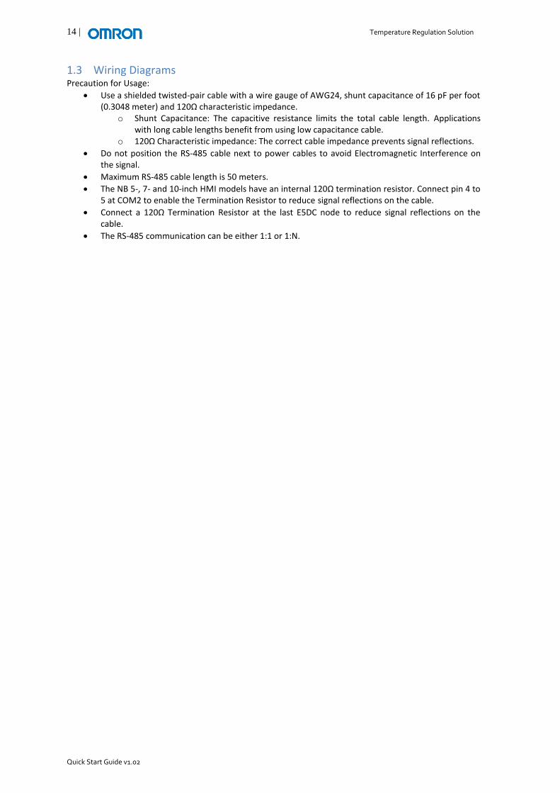
1.3 Wiring Diagrams Precaution for Usage:
Use a shielded twisted-pair cable with a wire gauge of AWG24, shunt capacitance of 16 pF per foot (0.3048 meter) and 120Ω characteristic impedance.
o Shunt Capacitance: The capacitive resistance limits the total cable length. Applications with long cable lengths benefit from using low capacitance cable.
o 120Ω Characteristic impedance: The correct cable impedance prevents signal reflections.
Do not position the RS-485 cable next to power cables to avoid Electromagnetic Interference on the signal.
Maximum RS-485 cable length is 50 meters.
The NB 5-, 7- and 10-inch HMI models have an internal 120Ω termination resistor. Connect pin 4 to 5 at COM2 to enable the Termination Resistor to reduce signal reflections on the cable.
Connect a 120Ω Termination Resistor at the last E5DC node to reduce signal reflections on the cable.
The RS-485 communication can be either 1:1 or 1:N.

Temperature Regulation Solution | 15
Quick Start Guide v1.02
1.3.1 One Panel Figure 11 Wiring Diagram using one panel illustrates the wiring diagram between the NB HMI COM2 and E5_C Temperature Controllers in a single panel. The cable shielding connected to the FG connection located at COM2 of the Compact NB HMI.
Pin No.Pin No.
TerminatorTerminator 44
TerminatorTerminator 55
RDB+RDB+ 66
RDA-RDA- 88
FGFG
Pin No.Pin No.
33 B (+)B (+)
44 A (-)A (-)
E5DCRS-485
NB HMICOM2
RS-485
Pin No.Pin No.
1414 A (-)A (-)
1313 B (+)B (+)
E5CCRS-485
Pin No.Pin No.
1313 B (+)B (+)
1414 A (-)A (-)
E5CCEnd NodeRS-485
Terminator120 Ω
(½ W)
Up to 32 Nodes can be connected, including the NB HMI
PanelThe cable shielding is connected to the FG connection at COM2 of the NB HMI.
Continue shielding connection for all E5_C within the same panel.
Figure 11 Wiring Diagram using one panel

16 | Temperature Regulation Solution
Quick Start Guide v1.02
1.3.2 Multiple Panels Mounting the equipment on multiple Panels changes the method required to connect the shielding. Signal disruption from Electrical Magnetic Interference is more likely with this configuration therefore it is not recommendable to connect the cable shielding at the FG connection at COM2 of the Compact NB HMI. Instead, connect the RS-485 cable shielding on both sides at the panels ground connection as illustrated in Figure 12 Cable diagram using multiple panels.
Panel 1 Panel 2
NB HMI
E5_C
RS-485 Communication Cable
Shielding Clip
Panel 3
E5_C
RS-485 Communication Cable
E5_C
Figure 12 Cable diagram using multiple panels For optimal protection against potential Electromagnetic Interference within the panels, continue the cable shielding until the communication cable reaches the equipment. Only remove the cable insulation where the cable should connect with the shielding clip. It is recommended not to remove the cable shielding after the shielding clip. Refer to Figure 13 Wiring Diagram using multiple panels for the wiring diagram.

Temperature Regulation Solution | 17
Quick Start Guide v1.02
Pin No.Pin No.
TerminatorTerminator 44
TerminatorTerminator 55
RDB+RDB+ 66
RDA-RDA- 88
FGFG
Pin No.Pin No.
33 B (+)B (+)
44 A (-)A (-)
E5DCRS-485
NB HMICOM2
RS-485
Pin No.Pin No.
1414 A (-)A (-)
1313 B (+)B (+)
E5CCRS-485
Pin No.Pin No.
1313 B (+)B (+)
1414 A (-)A (-)
E5CCEnd NodeRS-485
Terminator120 Ω
(½ W)
Up to 32 Nodes can be connected, including the NB HMI
Connect the cable shielding at both sides at the Panels ground connection using Shielding Clips.
Continue shielding connection for all E5_C within the same panel.
Connect the cable shielding at both sides at the Panels ground connection using Shielding Clips.
Panel 1
Panel 2
Panel 3
Figure 13 Wiring Diagram using multiple panels

18 | Temperature Regulation Solution
Quick Start Guide v1.02
1.4 Communication Settings The following section describes how to setup communication between the Compact NB HMI and E5_C Temperature Controllers using Modbus RTU protocol.
NB-Designer The methods below explain the NB-Designer configuration procedure. The first method illustrates how to visual configure the network configuration. In order to reduce time in developing the network configuration, assigning a station number in screen objects such as ‘Number Inputs’ is also possible. Method 2 describes how to assign station numbers in screen objects. Method 1: Visually Design your Network Configuration.
I. Design your network configuration, for example:
Temperature Regulation Solution | 19
Quick Start Guide v1.02
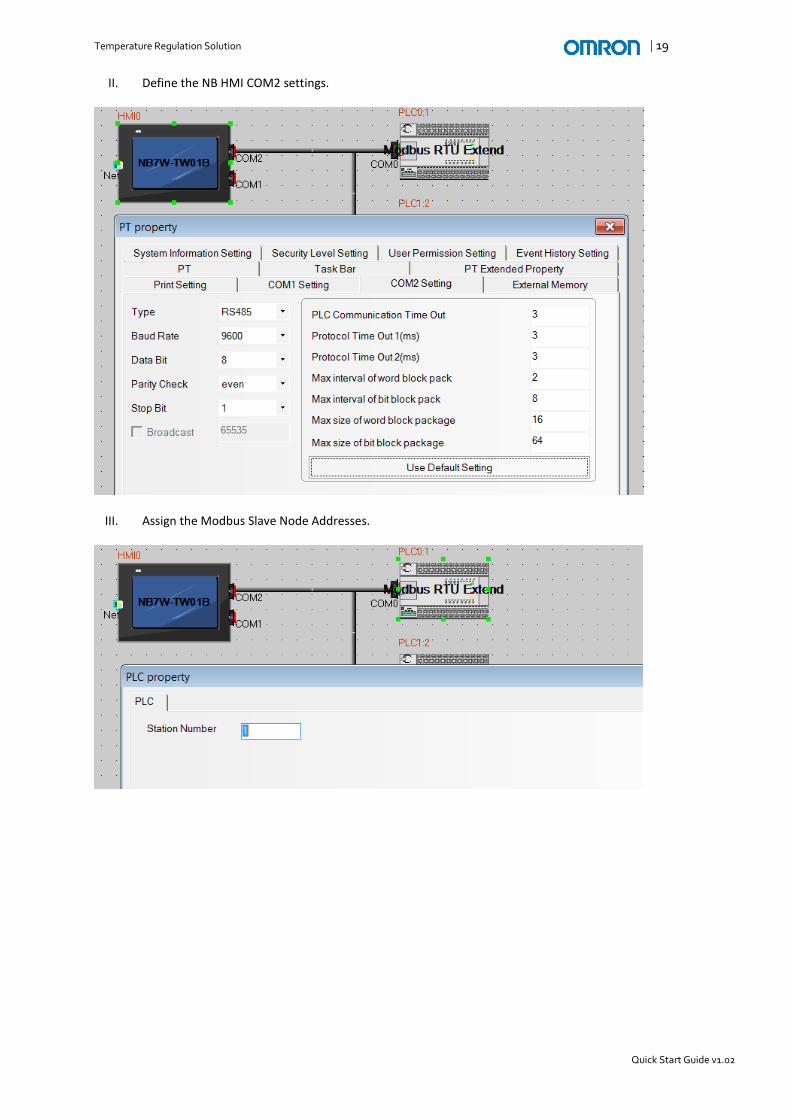
II. Define the NB HMI COM2 settings.
III. Assign the Modbus Slave Node Addresses.

20 | Temperature Regulation Solution
Quick Start Guide v1.02
Method 2: Assign the Modbus Slave Node Address directly in screen objects
I. Design the network configuration as shown below.
II. Define the NB HMI COM2 settings.

Temperature Regulation Solution | 21
Quick Start Guide v1.02
III. Assign a different Modbus Slave Node Address using the ‘Change Station No.’ checkbox in screen objects.

22 | Temperature Regulation Solution
Quick Start Guide v1.02
Temperature Controller The Compact NB HMI communicates with the E5_C Temperature Controllers using the Modbus RTU protocol. The steps below describe how to configure the TC.
I. Configure the following essential Temperature Controller parameters4 as shown below.
Parameter Name Displayed characters Setting Range Description
Protocol Setting
Modbus Protocol
Unit Number
1 to 99 Modbus Slave Node Address5
Baud rate
9.6 : 9600 19.2 : 19200 38.4 : 38400 57.6 : 57600
Baud rate in bits / second
Data Length
8 (bit) Data Length is fixed
Stop Bits
1 or 2 Depends on Parity: Even / Odd : 1 None : 2
Parity
None Even Odd
Send Data Wait Time
0 to 99 ms
When the Protocol is set to Modbus, the following communication parameters are applicable: • Data Length = 8 bits ( the data length is fixed for Modbus communication ) • Stop bits = 1 ( when parity is Even or Odd )
= 2 ( when parity is None ) The ‘Data Length’ and ‘Stop Bits’ parameters are not displayed when the Protocol Setting parameter is set to Modbus.
4 Appendix B: E5_C Communication Parameter Setup describes how to navigate to the communications
setting level using the TCs interface buttons. 5 Apply the Modbus Slave Node Address as configured in NB-Designer.

Temperature Regulation Solution | 23
Quick Start Guide v1.02
II. Configure the optional communication related parameter as shown below.
Parameter Name Displayed characters Setting Range Description
Communications Writing
ON or OFF
ON: The TC parameters are Read / Write for external devices such as the Compact CP1 PLC. OFF: The TC parameters are Read Only for external devices. It is recommendable to set this parameter ON to enable Read / Write actions for the TC parameters from the Compact CP1 PLC.

24 | Temperature Regulation Solution
Quick Start Guide v1.02
1.5 Modbus RTU Protocol The following section describes the Modbus RTU Communication between the Compact NB HMI and E5_C Temperature Controller(s).
1.5.1 Modbus Registers The following table lists several standard Modbus registers. The items expressed in hexadecimal in the "Setting (monitor) value" column are the setting range in the Modbus specifications. Values in parentheses "()" are the actual setting range.
Modbus
Register
(2-byte)
Parameter
Name Setting (monitor) value Level
#2402 PV Temperature: Use the specified range for each sensor. Analog: Scaling lower limit − 5% FS to Scaling upper limit + 5% FS
Operation #2103 Set Point SP lower limit to SP upper limit
#2406 Status 6 7 Refer to section 1.5.2 Status Details
#2407 Status 8 Refer to section 1.5.2 Status Details
#2D0F Set Point Upper Limit
The range of values (without decimal point) is as follows: Temperature input: SP lower limit + 1 to Input range upper limit Analog input: SP lower limit + 1 to Scaling upper limit
Initial Setting #2D10
Set Point Lower Limit
The range of values (without decimal point) is as follows: Temperature input: Input range lower limit to SP upper limit − 1 Analog input: Scaling lower limit to SP upper limit − 1
#2708 Control Period (heating)
H'FFFFFFFE (−2): 0.1 s H'FFFFFFFF (−1): 0.2 s H'00000000 (0): 0.5 s H'00000001 to H'00000063 (1 to 99)
#2A00 Proportional Band
H'00000001 to H'0000270F (0.1 to 999.9)
Adjustment #2A01 Integral Time
Standard, heating/cooling, or close position proportional control: H'00000000 to H'0000270F (0 to 9999: Integral/derivative time unit is 1 s.) (0.0 to 999.9: Integral/derivative time unit is 0.1 s.) Floating position-proportional control: H'00000001 to H'0000270F (1 to 9999: Integral/derivative time unit is 1 s.) (0.1 to 999.9: Integral/derivative time unit is 0.1 s.)
#2A02 Derivative Time H'00000000 to H'0000270F (0 to 9999: Integral/derivative time unit is 1 s.) (0.0 to 999.9: Integral/derivative time unit is 0.1 s.)
Please refer to H175-E1-08 E5_C Digital Temperature Controllers Communications Manual, section 5-1 Variable Area (Setting Range) List for the complete Modbus register list.
6 The parameter ‘Status’ is not displayed on the Controller display.
7 In 2-byte mode, the rightmost 16 bits are read.
8 In 2-byte mode, the leftmost 16 bits are read.

Temperature Regulation Solution | 25
Quick Start Guide v1.02
1.5.2 Status Details The following table describes the ‘Status’ parameter in detail.
Bit position Status Bit Description
0 1
Status ( lower word )
0 Heater overcurrent (CT1) Not generated Generated
1 Heater current hold (CT1) Update Hold
2 A/D converter error Not generated Generated
3 HS alarm (CT1) OFF ON
4 RSP input error Not generated Generated
5 - OFF -
6 Input error Not generated Generated
7 Potentiometer input error Not generated Generated
8 Control output (heating) / open output
OFF ON
9 Control output (cooling)/close output OFF ON
10 HB (heater burnout) alarm (CT1) OFF ON
11 HB (heater burnout) alarm (CT2) OFF ON
12 Alarm 1 OFF ON
13 Alarm 2 OFF ON
14 Alarm 3 OFF ON
15 Program end output OFF ON
Status ( upper word )
16 Event input 1 OFF ON
17 Event input 2 OFF ON
18 Event input 3 OFF ON
19 Event input 4 OFF ON
20 Write mode Backup mode RAM write mode
21 Non-volatile memory RAM = Non-volatile memory
RAM ≠ Non-volatile memory
22 Setup area Setup area 0 Setup area 1
23 AT execute/cancel AT canceled AT execution in progress
24 RUN/STOP Run Stop
25 Communications writing OFF (disabled) ON (enabled)
26 Auto/manual switch Automatic mode Manual mode
27 Program start Reset Start
28 Heater overcurrent (CT2) Not generated Generated
29 Heater current hold (CT2) Update Hold
30 - OFF -
31 HS alarm (CT2) OFF ON
Precaution for usage:
Status bits marked as “-” are always OFF.
When read in setup area 1, the status of the bits will be as follows: o Overcurrent: Last value held o A/D converter error: Last value held o Input error: Last value held o HB and HS outputs: Cleared o Program end output: Cleared o Current hold: Last value held o Heating and cooling outputs: Cleared o Alarm outputs: Cleared
Status (lower Word) Bit 1: When the control output ON time is less than 30 ms for a control period of 0.1 s or 0.2 s or when it is less than 100 ms for any other control period, the bit is set to “1” and the heater current is held at the last current value.

26 | Temperature Regulation Solution
Quick Start Guide v1.02
1.5.3 Assigning Modbus Registers in NB-Designer The Compact NB HMI supports several Modbus communication protocols. The most notable protocols are Modbus RTU, Modbus ASCII and Modbus TCP. The Compact NB HMI uses different communication drivers of the Modbus RTU in terms of using Function Codes. The most extensive Modbus communication driver is Modbus RTU Extend. Modbus RTU Extend supports a wide range of function codes. Please refer to V108 Host Connection Manual for more information about the different Modbus communication drivers for the Compact NB HMI. The E5_C Temperature Controller supports function code #06 Write Single Variable / Operation Command. The only Modbus communication driver that supports function code #06 is the Modbus RTU Extend communication driver. Therefore, the following information refers to Modbus RTU Extend when using Modbus communication. Section 1.4 Communication Settings described how to visual design the Modbus network within NB-Designer as illustrated in Figure 14 NB-Designer Network Configuration pane. This section continues explaining how to register Modbus registers for Modbus Node 1.
Figure 14 NB-Designer Network Configuration pane 1.5.1 Modbus Registers illustrated several parameters to read from the TC. The Modbus Address allocation provided is in hexadecimal format however, NB-Designer uses the decimal format. For example: The hexadecimal address of the Process Value is #2402. Converting the address into a decimal format reads &9218. NB-Designer uses an offset of +1 for the Modbus Address allocation because an address allocation of 0 is invalid in NB-Designer. As a result, the Modbus register allocated for the Process Value is &9219 as shown in Figure 15 Assigning the Process Value register as Modbus Address. Set the Area / Variable setting to 4X.

Temperature Regulation Solution | 27
Quick Start Guide v1.02
Figure 15 Assigning the Process Value register as Modbus Address The Modbus Address offset allocation is applicable for all Modbus communication drivers.

28 | Temperature Regulation Solution
Quick Start Guide v1.02
2 IN-PANEL TEMPERATURE REGULATION The following chapter describes the In-Panel Temperature Regulation solution.
2.1 Introduction The In-Panel Temperature Regulation solution consists of three OMRON products, respectively the E5DC In-Panel Temperature Controller, Compact CP1 PLC and the Compact NB HMI. The CP1 PLC uses the CP1W-CIF11 / CIF12 option board to support RS-485 communication between the PLC and the Temperature Controllers. The communication between the devices is programless and it just requires configuring the parameters within the temperature controllers to establish communication. ‘Programless Communication’ features reading and writing parameters from and to the temperature controller from user specified data memory addresses located in the CP1 PLC. Up to 32 temperature controllers can connect to a CP1 PLC. The PLC is the central hub for controlling the process while it also contains the functionality to communicate with a Compact NB HMI. The Compact NB HMI adds valuable features such as visual displaying the course of temperature within a specified amount of time. It can log the trend data onto an external memory in .csv format for easy reading and can also read / write specific parameters to the Temperature Controller(s) via the CP1 PLC.

Temperature Regulation Solution | 29
Quick Start Guide v1.02
2.2 Programless Communication This section describes the ‘Programless Communication’ feature of the E5_C Temperature Controllers.
2.2.1 Introduction The ‘Programless Communication’ feature in the E5_C Temperature Controllers enables easy and convenient communication between the Compact CP1 PLC and the Temperature Controllers. Up to 32 E5_C controllers can connect to the PLC. Each E5_C controller has 30 Words allocated in the PLC memory that automatically synchronizes if communication is established. Each individual E5_C can assign up to 13 parameters for both reading and writing from and to the PLC memory. In total 26 parameters are synchronized between the PLC and the Temperature Controller. The PLC memory allocation is user defined and therefore provides the flexibility to customize according the user preferences. Figure 16 PLC Memory Allocation illustrates the PLC memory allocation when assigned multiple Temperature Controllers.
No. 0Upload Area
No. 0Download Area
No. 1Upload Area
No. 1Download Area
No. 2Upload Area
No. 2Download Area
E5DCNo. 0
E5DCNo. 1
E5DCNo. 2
30 Words allocated in the
PLC Memory
PV, status, etc.
Set point, alarm value, etc.
PLC Memory
Figure 16 PLC Memory Allocation

30 | Temperature Regulation Solution
Quick Start Guide v1.02
2.2.2 Communication Process The Master (the E5_C Controller with communication unit number 0) starts ‘Programless Communication’ approximately five seconds after the power supply is on. When the master starts communication, the slaves (the E5_C Controllers with a communication unit number other than 0) also start communication. Figure 17 Communication Process illustrates the process of the ‘Programless Communication’ starting at Unit No. 0, the master unit. The master unit shall first start synchronizing the data with the Compact CP1 PLC. After the master finished synchronizing the data, Unit No. 1 shall start synchronizing the data with the Compact CP1 PLC. This process continues until the highest communications unit number has completed the synchronize process, then the process restarts at Unit No. 0.
Figure 17 Communication Process Please refer to H175 E5_C Digital Temperature Controllers Communications manual, section 6-1 Programless Communication for more information about the ‘Programless Communication’ feature. Precautions for Usage:
‘Programless Communication’ is supported with the following product versions: o E5CC version 1.1 or higher o E5EC version 1.1 or higher o E5AC version 1.1 or higher o E5DC version 1.0 or higher o E5GC version 2.2 or higher
‘Programless Communication’ uses RS-485 as the communication method.
The communication does not start until the power supply to the master is on.
The communication cycle will increase while waiting for communication from the stopped E5_C Controllers.
After communication has started, it will continue for the remaining E5_C Controllers even if one or more (including the master) stops.
Assign unit numbers in sequential order, for example 0, 1, 2, 3, etc. otherwise communication issues shall occur.
Unit No. 0:
Master
Unit No. 1:
Slave
Unit No. 2:
Slave
Unit No. 3:
Slave
Highest Unit No.

Temperature Regulation Solution | 31
Quick Start Guide v1.02
2.3 System Configuration As mentioned in the previous section RS-485 communications is required for ‘Programless Communication’ between the Compact PLC and Temperature Controllers. The CP1W-CIF11 (/ CIF12) option board add RS-485 / RS-422 communication to the Compact CP1 PLC. The option board is mandatory for the Compact CP1 PLCs in all configurations to support RS-485 communication with the Temperature Controllers. The only exception is the CP1E-N_S1 model, which supports a built-in RS-485 port. Achieving communication between the Compact HMI and PLC is accomplished using various methods such as Serial and Ethernet. The first communication method is serial using RS-232, RS-485 or RS-422 with all NB HMI models. RS-232 is the most common serial connection and therefore this document only refers to the RS-232 method. RS-232 serial communication supports a 1:1 connection only. The CP1W-CIF01 option board supports RS-232 communication. The CP1E model support built-in port supports RS-232 communication. The second communication method is Ethernet related. The Ethernet configuration utilizes the CP1L-E with built-in Ethernet port to achieve Ethernet communication with the NB HMI. Table 1 System Configurations illustrate what products are required to achieve specific configurations. Table 1 System Configurations
Product Serial CP1E Serial CP1E-N_S1 Serial CP1L-E Ethernet
NB__-TW00B Yes Yes Yes -
NB__-TW01B Yes Yes Yes Yes
E5DC Yes Yes Yes Yes
CP1E Yes - -
CP1E-N_S1 - Yes - -
CP1L-E - - Yes Yes
CP1W-CIF01 - - Yes -
CP1W-CIF11 / CIF12 Yes - Yes Yes
Please refer to Appendix A: E5_C Hardware Information for detailed product information about the E5_C Temperature Controllers, such as model selection and pin-out. The next paragraphs contain the various communication configuration overviews.

32 | Temperature Regulation Solution
Quick Start Guide v1.02
2.3.1 Serial The configuration consists of the following products:
Compact NB HMI (non-model specific)
Compact CP1 PLC CP1E with built-in RS-232 Port CP1L-E + CP1W-CIF01 RS-232 Option Board
XW2Z-200T or XW2W-500T communication cable
CP1W-CIF11 or CIF12 Option Board
E5DC Temperature Controllers
NB HMI
CP1E ( or CP1L-E )
E5DCNo. 0
E5DCNo. 1
E5DCNo. 2
Serial Communication
CP1E:Built-in RS-232 Port
CP1L-E: CP1W-CIF01
CP1W-CIF11 / CIF12
Programless Serial Communication
Precaution for usage:
Please refer to W479 CP1E CPU Unit Hardware User Manual for detailed information about CP1E models.
Please refer to W516 CP1L-EL/EM CPU Unit Operation Manual for detailed information about CP1L-E models.
CP1L-E Firmware Version 1.06 or higher is required.
CP1L-E produced with the following Lot No.9 use firmware version 1.06 or higher:
o CP1L-EL20 : Lot No. 11813M or later o CP1L-EM30 : Lot No. 18813M or later o CP1L-EM40 : Lot No. 24813M or later
Please contact your local OMRON representative if the manufactured CP1L-E has a Lot No. of an earlier date than the provided Lot No. above.
CX-Programmer version 9.4 or higher is required for the CP1L-E model.
9 The following example explains how to interpret the Lot No. code: 11813M = 11 August 2013.

Temperature Regulation Solution | 33
Quick Start Guide v1.02
2.3.2 Serial CP1E-N_S1 The configuration consists of the following products:
Compact NB HMI (non-model specific)
Compact CP1E-N_S1 PLC with built-in RS-232 and RS-485 Ports
XW2Z-200T or XW2W-500T communication cable
E5DC Temperature Controllers
CP1E-N_S1
NB HMI
E5DCNo. 0
E5DCNo. 1
E5DCNo. 2
Serial Communication
Built-in RS-232 Port
Built-in RS-485 port
Programless Serial Communication
Precaution for usage:
CJ1W-CIF11 converter module cannot be connected to the built-in RS-232 port of the CP1E-N_S(1) model.

34 | Temperature Regulation Solution
Quick Start Guide v1.02
2.3.3 Ethernet The configuration consists of the following products:
Compact NB HMI (-TW01B model only)
Compact CP1L-E with built-in Ethernet Port PLC
CP1W-CIF11 or CIF12 RS-485/422 option board
E5DC Temperature Controllers
NB HMI-TW01B only
CP1L-E
E5DCNo. 0
E5DCNo. 1
E5DCNo. 2
Ethernet Communication
CP1W-CIF11/12
Programless Communication
Precaution for usage:
CP1L-E Firmware Version 1.06 or higher is required.
CP1L-E produced with the following Lot No.10
use firmware version 1.06 or higher: o CP1L-EL20 : Lot No. 11813M or later o CP1L-EM30 : Lot No. 18813M or later o CP1L-EM40 : Lot No. 24813M or later
Please contact your local OMRON representative if the manufactured CP1L-E has a Lot No. of an earlier date than the provided Lot No. above.
CX-Programmer version 9.4 or higher is required for the CP1L-E model.
10
The following example explains how to interpret the Lot No. code: 11813M = 11 August 2013.

Temperature Regulation Solution | 35
Quick Start Guide v1.02
2.4 Wiring Diagrams Precaution for Usage: Generic
Use a shielded twisted-pair cable with a wire gauge of AWG24, shunt capacitance of 16 pF per foot and 120Ω characteristic impedance.
o Shunt Capacitance: The capacitive resistance limits the total cable length. Applications with long cable lengths benefit from using low capacitance cable.
o 120Ω Characteristic impedance: The correct cable impedance prevents signal reflections.
Do not position the RS-485 cable next to power cables to avoid Electromagnetic Interference on the signal.
Connect a 120Ω Termination Resistor at the last E5DC node to reduce signal reflections on the cable.
The RS-485 communication can be either 1:1 or 1:N. CP1W-CIF11 (/CIF12)
Turn on DIP Switch 1 to enable the Termination Resistor to reduce signal reflections on the cable.
Turn on DIP Switch 2 and 3 to enable RS-485 (2-wire) communication.
Turn on DIP Switch 5 and 6 to enable flow control in the serial communication.
CP1W-CIF11: Maximum cable length is 50 meters due to non-galvanic signal isolation.
CP1W-CIF12: Maximum cable length is 500 meters due to galvanic signal isolation.
CP1E-N_S1 Built-in RS-485 Port
The built-in RS-485 port has a single DIP Switch that enables the Termination Resistor. Turn it on to enable the Termination Resistor to reduce signal reflections on the cable.
The maximum cable length is 50 meters.

36 | Temperature Regulation Solution
Quick Start Guide v1.02
2.4.1 One Panel
CP1W-CIF11 (/ CIF12) Option Board Figure 18 CP1W-CIF11 / CIF12 wiring diagram using one panel illustrates the wiring diagram between the CP1W-CIF11 / CIF12 and E5DC Temperature Controllers.
RDA- RDB+ SDA- SDB+ FG
Pin No.Pin No.
33 B (+)B (+)
44 A (-)A (-)
E5DCRS-485
Pin No.Pin No.
44 A (-)A (-)
33 B (+)B (+)
E5DCRS-485
Terminator120 Ω
(½ W)
CP1W-CIF11/12
Pin No.Pin No.
33 B (+)B (+)
44 A (-)A (-)
E5DCEnd NodeRS-485
Up to 32 Nodes can be connected, excluding the NB HMI
Panel
The cable shielding is connected to the FG connection at COM2 of the NB HMI.
Continue shielding connection for all E5_C within the same panel.
Figure 18 CP1W-CIF11 / CIF12 wiring diagram using one panel

Temperature Regulation Solution | 37
Quick Start Guide v1.02
CP1E-N_S1 Built-in RS-485 Port Figure 19 CP1E-N_S1 built-in RS-485 port wiring diagram using one panel illustrates the wiring diagram between the built-in RS-485 port and E5DC Temperature Controllers.
CP1E-N_S1Built-in RS-485 Port
Pin No.Pin No.
33 B (+)B (+)
44 A (-)A (-)
E5DCRS-485
Pin No.Pin No.
44 A (-)A (-)
33 B (+)B (+)
E5DCRS-485
Terminator120 Ω
(½ W)
Pin No.Pin No.
33 B (+)B (+)
44 A (-)A (-)
E5DCEnd NodeRS-485
Up to 32 Nodes can be connected, excluding the NB HMI
Panel
The cable shielding is connected to the FG connection at COM2 of the NB HMI.
Continue shielding connection for all E5_C within the same panel.
Figure 19 CP1E-N_S1 built-in RS-485 port wiring diagram using one panel

38 | Temperature Regulation Solution
Quick Start Guide v1.02
2.4.2 Multiple Panels Mounting the equipment in multiple Panels changes the method used to connect the shielding. Signal disruption from Electrical Magnetic Interference is more likely with this configuration therefore it is not recommendable to connect the cable shielding at the FG connection at the built-in RS-485 port or CP1W-CIF11 / CIF12. Instead, connect the RS-485 cable shielding on both sides at the panels ground connection as illustrated in Figure 20 Cable diagram using multiple panels.
CP1
Panel 1 Panel 2
RS-485 Communication Cable
Shielding Clip
Panel 3
RS-485 Communication Cable
E5_C E5_C E5_C
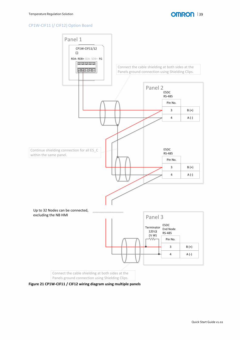
Figure 20 Cable diagram using multiple panels For optimal protection against potential Electromagnetic Interference within the panels, continue the cable shielding until the communication cable reaches the equipment. Only remove the cable insulation where the cable should connect with the shielding clip. It is recommended not to remove the cable shielding after the shielding clip. Refer to Figure 21 CP1W-CIF11 / CIF12 wiring diagram using multiple panels and Figure 22 CP1E-N_S1 Built-in RS-485 Port wiring diagram using multiple panels below.
Temperature Regulation Solution | 39
Quick Start Guide v1.02
CP1W-CIF11 (/ CIF12) Option Board
RDA- RDB+ SDA- SDB+ FG
Pin No.Pin No.
33 B (+)B (+)
44 A (-)A (-)
E5DCRS-485
Pin No.Pin No.
44 A (-)A (-)
33 B (+)B (+)
E5DCRS-485
Terminator120 Ω
(½ W)
CP1W-CIF11/12
Pin No.Pin No.
33 B (+)B (+)
44 A (-)A (-)
E5DCEnd NodeRS-485
Up to 32 Nodes can be connected, excluding the NB HMI
Panel 1
Continue shielding connection for all E5_C within the same panel.
Connect the cable shielding at both sides at the Panels ground connection using Shielding Clips.
Panel 2
Panel 3
Connect the cable shielding at both sides at the Panels ground connection using Shielding Clips.
Figure 21 CP1W-CIF11 / CIF12 wiring diagram using multiple panels

40 | Temperature Regulation Solution
Quick Start Guide v1.02
CP1E-N_S1 Built-in RS-485 Port
Pin No.Pin No.
33 B (+)B (+)
44 A (-)A (-)
E5DCRS-485
Pin No.Pin No.
44 A (-)A (-)
33 B (+)B (+)
E5DCRS-485
Terminator120 Ω
(½ W)
Pin No.Pin No.
33 B (+)B (+)
44 A (-)A (-)
E5DCEnd NodeRS-485
Up to 32 Nodes can be connected, excluding the NB HMI
Panel 1
Continue shielding connection for all E5_C within the same panel.
Connect the cable shielding at both sides at the Panels ground connection using Shielding Clips.
Panel 2
Panel 3
Connect the cable shielding at both sides at the Panels ground connection using Shielding Clips.
Figure 22 CP1E-N_S1 Built-in RS-485 Port wiring diagram using multiple panels

Temperature Regulation Solution | 41
Quick Start Guide v1.02
2.5 Communication Settings
2.5.1 HMI Connection Methods The following paragraph describes how to setup Ethernet or Serial communication between the Compact NB HMI and CP1 PLC. Method 1: Serial As explained in section 2.3 System Configuration, serial communication shall be accomplished using CP1W-CIF01 RS-232 option board or Built-in RS-232 Port of the CP1E PLC model.
I. Configure the Compact CP1 PLC serial port using CX-Programmer as shown below.

42 | Temperature Regulation Solution
Quick Start Guide v1.02
II. Design the network configuration in NB-Designer as shown below.
III. Define the PLC Settings.

Temperature Regulation Solution | 43
Quick Start Guide v1.02
IV. Define the NB HMI COM1 Settings.

44 | Temperature Regulation Solution
Quick Start Guide v1.02
Method 2: Ethernet Ethernet communication is standard available when using the Compact NB HMI–TW01B and the CP1L-E models. The Compact NB HMI–TW00B models do not support Ethernet communication.
I. Configure the Compact CP1 PLC built-in Ethernet port using CX-Programmer as shown below.
The FINS Node No. should be equal to the IP address last digit, as illustrated above.
II. Design the network configuration in NB-Designer as shown below.

Temperature Regulation Solution | 45
Quick Start Guide v1.02
III. Define the PLC Settings.
IV. Define the NB HMI Ethernet Port Settings.

46 | Temperature Regulation Solution
Quick Start Guide v1.02
V. Define the Communication Settings.

Temperature Regulation Solution | 47
Quick Start Guide v1.02
2.5.2 TC Connection Method The Compact CP1 PLC communicates with the E5_C Temperature Controllers using Host Link (FINS) over the RS-485 protocol. The CP1 requires the CP1W-CIF11/12 option board to support RS-485 communication for compatibility with the TC. The steps below describe how to establish communication between the PLC and TC.
I. Configure the Compact CP1 PLC serial port using CX-Programmer as shown below.

48 | Temperature Regulation Solution
Quick Start Guide v1.02
II. Configure the following essential Temperature Controller parameters11
as shown below.
Parameter Name Displayed characters Setting Range Description
Protocol Setting
Host Link (FINS)
Unit Number
0 to 99 0 : Master 1 to 31 : Slave
Baud rate
9.6 : 9600 19.2 : 19200 38.4 : 38400 57.6 : 57600*
Baud rate in bit / second * Recommended baud rate when using OMRON PLCs
Send Data Wait Time
0 to 99 ms
Highest Communications Unit No.
0 to 99 Set the Unit No. of the last E5_C in the RS-485 network.
Area
0 : DM 13 : EMC 1 : EM0 14 : EMD 2 : EM1 15 : EME 3 : EM2 16 : EMF 4 : EM3 17 : EM10 5 : EM4 18 : EM11 6 : EM5 19 : EM12 7 : EM6 20 : EM13 8 : EM7 21 : EM14 9 : EM8 22 : EM15 10 : EM9 23 : EM16 11 : EMA 24 : EM17 12 : EMB 25 : EM18
Applicable address range for the Memory Areas : 0 to 32767
First Address Upper Word
0 to 99 Specify the first address of the PLC (upper word).
First Address Lower Word
0 to 9999 Specify the first address of the PLC (lower word).
Receive Data Wait Time
100 to 9999 ms
Communications Node Number
0 to 99 Specify Host Link unit number for the OMRON PLC.
Upload Settings 1 to 13
0 to 98 Specify (13) read parameters from E5_C.
Download Settings 1 to 13
30 to 98 Specify (13) write parameters to E5_C.
11
Appendix B: E5_C Communication Parameter Setup describes how to navigate to the communications setting level using the interface buttons on the TC.

Temperature Regulation Solution | 49
Quick Start Guide v1.02
III. Configure optional communication related parameters as shown below.
Parameter Name Displayed characters Setting Range Description
Communications Writing
ON or OFF
ON: The TC parameters are Read / Write for external devices such as the Compact CP1 PLC. OFF: The TC parameters are Read Only for external devices. It is recommendable to set this parameter ON to enable Read / Write actions for the TC parameters from the Compact CP1 PLC.
Communications Monitor
-
Read the total communication cycle time between all participating TCs and the PLC. The measured cycle time is shown in milliseconds. During normal operation, the range is 0 to 9999 ms. If the cycle time exceeds 9999 ms then the following characters are displayed:
If an error occurs then the following characters are displayed:
If the ‘Communication Monitor’ parameter is stored in the PLC memory, the cycle time is shown as 0 to FFFF hex (0 to 65,535 decimal). An error is indicated by FFFF hex.
Please refer to manual H175-E1-08 E5_C Digital Temperature Controllers Communications Manual, section 6-2 E5_C Setup for more information about configuring the E5_C for ‘Programless Communication’.

50 | Temperature Regulation Solution
Quick Start Guide v1.02
3 IN-PANEL INTEGRATED TEMPERATURE REGULATION The following chapter describes the In-Panel Integrated Temperature Regulation solution.
3.1 Introduction The In-Panel Integrated Temperature Regulation solution consists of three OMRON products, respectively the Compact CP1 PLC, CP1W-TS Temperature Sensor Units and the Compact NB HMI. The CP1W-TS is an expansion unit of the CP1 PLC that primarily reads Thermocouple or Platinum Resistance Thermometer Inputs but can also read Analog Inputs
12. The solution utilizes a 2-PID Function Block
13 that simultaneously
achieves two characteristics, set point tracking and disturbance suppression. The Compact NB HMI adds valuable features such as visual displaying the course of temperature within a specified amount of time. It can log the trend data onto an external memory in .csv format for easy reading and can also read / write specific parameters from and to the Temperature Controller(s).
12
The CP1W-TS003 Temperature Sensor Unit also supports Analog Inputs. 13
The CP1L(-E) models support Function Blocks. The CP1E model does not support Function Blocks.

Temperature Regulation Solution | 51
Quick Start Guide v1.02
3.2 Temperature Control 2-PID Function Block The following section describes the functionality of the Temperature Control 2-PID Function Block for the CP1W-TS Expansion Units.
3.2.1 Symbol Figure 23 TC 2-PID Function Block Symbol Overview shows the outline of the Function Block.
P_On
(BOOL)EN
TC_2PID_function_block
Function Block Name
Process Variable(INT)Process Value
Set Point Variable(INT)Set Point
Maximum Set Point Variable(INT)Maximum
Minimum Set Point Variable(INT)Minimum
Control Period for output R(WORD)Control_Period
Proportional Band Input(INT)P_Input
Integral Input(INT)I_Input
(BOOL)ENO
(BOOL)AT_Status
Auto Tuning Status Bit
(BOOL)Error
Error Status Bit
(INT)Status_Code
Status Code
(BOOL)Control_Output
PID Function Output
(WORD)OUT_P
Auto Tuning Proportional BandOutput
Activate PID Function(BOOL)Enable
Execute auto-tuning(BOOL)Start_AT
Stop auto-tuning(BOOL)Stop_AT
Derivative Input(INT)D_Input
Apply PID Input Values(BOOL)Write_PID_Inputs
(WORD)OUT_I
Auto Tuning Integral Output
(WORD)OUT_D
Auto Tuning Derivative Output
2PID Parameter(WORD)Filter_Coefficient
Reset Error(BOOL)Reset_Error
Figure 23 TC 2-PID Function Block Symbol Overview

52 | Temperature Regulation Solution
Quick Start Guide v1.02
3.2.2 Supported Models Table 2 Supported Sensor Input Type for the CP1W-TS Models indicates what sensor input type is supported with each CP1W-TS model. Table 2 Supported Sensor Input Type for the CP1W-TS Models
Model Input Description
CP1W-TS001 2 Thermocouple Type K or J Inputs
CP1W-TS002 4 Thermocouple Type K or J Inputs
CP1W-TS003 4 Thermocouple Type K or J Inputs (Input 3 and 4 can also operate as Analog Input; 0 to 10V, 1 to 5V or 4 to 20 mA)
CP1W-TS004 12 Thermocouple Type K or J Inputs
CP1W-TS101 2 Platinum Resistance Thermometer Type Pt100 or JPt100 Inputs
CP1W-TS102 4 Platinum Resistance Thermometer Type Pt100 or JPt100 Inputs
3.2.3 Conditions for Usage P_On (Always On Bit) should be connected to the EN input.
The Enable input operates the PID Control.
All input parameters should confirm the specification range.
3.2.4 Function Description The TC_2PID_function_block adds PID Control with Auto-Tuning feature for the CP1W-TS expansion units. Prerequisite for the Function Block to operate correctly, P_On (Always On Bit) should be connected to the EN Input. The PLC evaluates the function block status every PLC cycle. Simultaneously the Control Output is not operating unless the Enable input is on, thus preventing uncontrolled execution of any equipment controlled by the PID Control. The Process Value input is of sensor input type Thermocouple, Platinum Resistance Thermometer or Analog. The Set Point is user defined and related based on the type of sensor input plus the operating range of the sensor input. The operating range may differ per sensor type. The maximum and minimum parameters contain the operating range of the sensor input. Please consult the specific sensor datasheet for the accurate operating range. The P, I, D and Control Period parameters determine the responsiveness of the PID Control function. The P, I and D parameters can be configured using two different methods. The first method is configuring the parameters manually. The second method automatically detects the ideal parameters using the built-in Auto-Tuning (only AT-100% is supported, AT-40% is not supported) feature using the Limit Cycle method. While the Auto-Tuning process is in progress, the Auto-Tuning Status Bit is on. Once the Auto-Tuning is completed, the Auto-Tuning Status Bit is off and P, I and D Output parameters show the result of the Auto-Tuning process. Starting and stopping of the Auto-Tuning process is executed manually. The Control Period parameter defines the responsiveness of the Control Output. It evaluates at specified time interval the output status of the 2-PID function. Errors generated by the TC_2PID_function_block cause the Control Output to stop operating. In the event of an error, the Error Bit is on and the status code shall adjust accordingly. In order to continue the 2PID Control Function, the error has to be reset manually.
3.2.5 Function Block Precautions Switching off the Enable input causes the Control Output to turn off.
Invalid input values prohibit the Control_Output from operating. It remains off until the input parameters are within the correct range and resetting the error.
It is required to acknowledge an error using the Reset_Error input before the Function Block can operate.
3.2.6 EN Input Condition Connect P_On (Always On Bit) to EN Input in order to operate the Function Block.

Temperature Regulation Solution | 53
Quick Start Guide v1.02
3.2.7 Variable Restrictions Table 3 Variable Restrictions
Variable Type Restriction
Input Control_Period has an operating range from 1.00 to 99.99 seconds.
Input Maximum and Minimum Set Point Values should be consistent with the connected Temperature Sensor.
Input Filter_Coefficient has input range from α = 0.00 to 0.99 (#0100 to #0163).
Output The Auto-Tuning (AT-100%) process starts at the differential up signal at Start_AT.
Output The Auto-Tuning (AT-100%) process stops at the differential up signal at Stop_AT.
Output The AT_Status bit turns automatically off once the Auto-Tuning process is completed.
Output The OUT_P, OUT_I and OUT_D variables display the used PID parameters.
3.2.8 Status Codes Table 4 Status Codes
Status Code Description
#0000 No Error or Normal Operation
#0001 Manually Aborted Auto-Tuning (AT-100%)
#0002 Manually Started Auto-Tuning (AT-100%)
#0600 Invalid Input Entry at Control Period Input
#0601 Invalid PID parameter Settings detected
#0602 Invalid Input Entry at Minimum and/or Maximum Parameter Inputs
#0603 Invalid Input Entry at Filter Coefficient (2-PID parameter) α Input

54 | Temperature Regulation Solution
Quick Start Guide v1.02
3.2.9 Application Examples
Thermocouple Input
Figure 24 Thermocouple Input Example

Temperature Regulation Solution | 55
Quick Start Guide v1.02
Please confirm that all parameters are set and are within the range specification. Otherwise, an error occurs depending on what input parameter is invalid.
The data range at the Process Value that include one digit after the decimal point are stored without the decimal point, i.e., 10 times the actual value is stored, e.g. Unit: 0.1C° -> 500.0 C° = &5000 = #1388.
The Set Point parameter is the target value for the PID control system. Additional parameters related to Set Point are the Maximum and Minimum parameters. They define the maximum and minimum range for the Set Point parameter.
The PID parameters can be configured manually using P_Input, I_Input and D_Input. The Write_PID_Inputs input is required to write the PID input parameters.
If no PID parameters are stored, the function block shall generate a #0601 error when attempting to enable the 2-PID function. The user can manually start the Auto-Tuning Process causing the status code #0002 to occur. While the Auto-Tuning process in ongoing, the AT_Status bit is turned on and will turn off when the Auto-Tuning process has been completed.
OUT_P, OUT_I and OUT_D parameters are used as User Data Information outputs to inform the user what PID parameters are applicable for the 2-PID function.
The Control Period parameter defines the responsiveness of the Control Output. The operating range is 1.00 to 99.99 seconds. For example, when the Control Period is set to #0064 = &100 (1 second), the 2-PID function evaluates every 1 second whether to switch on or off the Control_Output.
The Error Bit turns on when an error has occurred. Please refer to Status Codes for detailed information regarding what type of error has occurred.

56 | Temperature Regulation Solution
Quick Start Guide v1.02
Analog Input (CP1W-TS003 Only)

Temperature Regulation Solution | 57
Quick Start Guide v1.02
Please confirm that all parameters are set and are within the range specification. Otherwise, an error occurs depending on what input parameter is invalid.
The data range at the Process Value is based on the Analog Input. For example, 4 to 20 mA is converted into #0000 to #2EE0.
The Set Point parameter is the target value for the PID control system. Additional parameters related to Set Point are the Maximum and Minimum parameters. They define the maximum and minimum range for the Set Point parameter.
The PID parameters can be configured manually using P_Input, I_Input and D_Input. The Write_PID_Inputs input is required to write the PID input parameters.
If no PID parameters are stored, the function block shall generate a #0601 error when attempting to enable the 2-PID function. The user can manually start the Auto-Tuning Process and a status code of #0002 shall occur. While the Auto-Tuning process in ongoing, the AT_Status bit is turned on and will turn off when the Auto-Tuning process has been completed.
OUT_P, OUT_I and OUT_D parameters are used as User Data Information outputs to inform the user what PID parameters are applicable for the 2-PID function.
The Control Period parameter defines the responsiveness of the Control Output. The operating range is 1.00 to 99.99 seconds. For example, when the Control Period is set to #0064 = &100 (1 second), the 2-PID function evaluates every 1 second whether to switch on or off the Control_Output.
The Error Bit turns on when an error has occurred. Please refer to Status Codes for detailed information regarding what type of error has occurred.
58 | Temperature Regulation Solution
Quick Start Guide v1.02
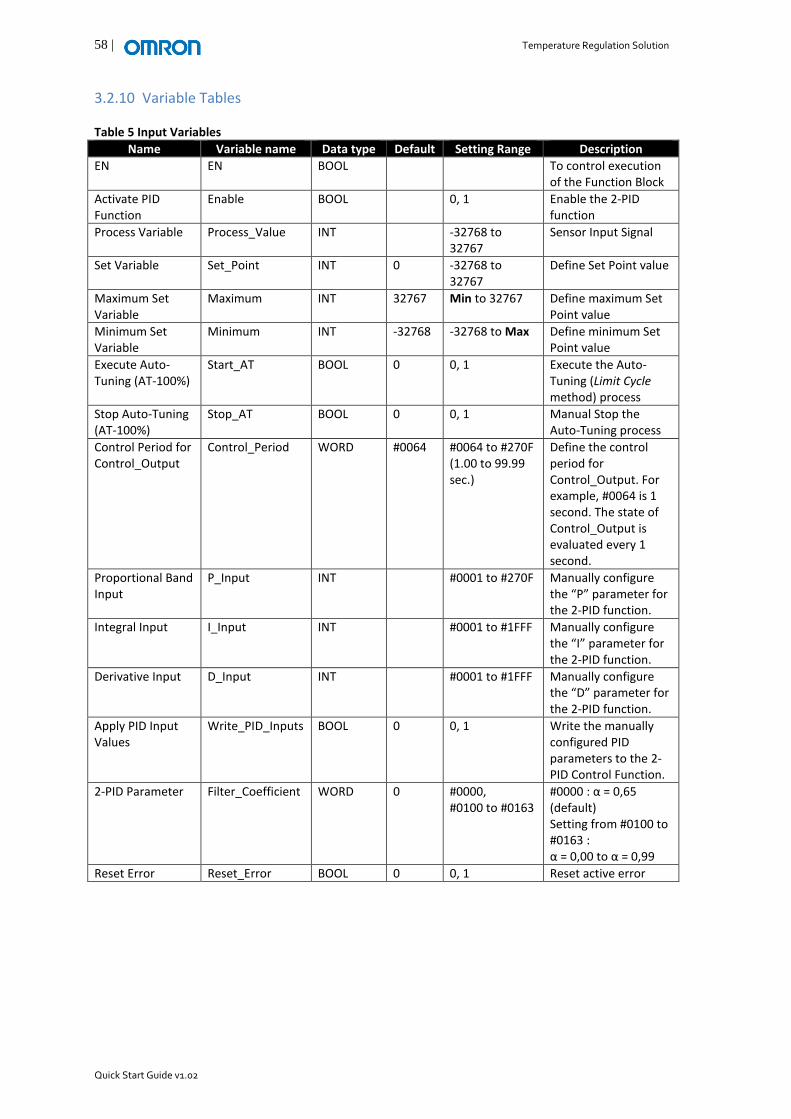
3.2.10 Variable Tables Table 5 Input Variables
Name Variable name Data type Default Setting Range Description
EN EN BOOL To control execution of the Function Block
Activate PID Function
Enable BOOL 0, 1 Enable the 2-PID function
Process Variable Process_Value INT -32768 to 32767
Sensor Input Signal
Set Variable Set_Point INT 0 -32768 to 32767
Define Set Point value
Maximum Set Variable
Maximum INT 32767 Min to 32767 Define maximum Set Point value
Minimum Set Variable
Minimum INT -32768 -32768 to Max Define minimum Set Point value
Execute Auto-Tuning (AT-100%)
Start_AT BOOL 0 0, 1 Execute the Auto-Tuning (Limit Cycle method) process
Stop Auto-Tuning (AT-100%)
Stop_AT BOOL 0 0, 1 Manual Stop the Auto-Tuning process
Control Period for Control_Output
Control_Period WORD #0064 #0064 to #270F (1.00 to 99.99 sec.)
Define the control period for Control_Output. For example, #0064 is 1 second. The state of Control_Output is evaluated every 1 second.
Proportional Band Input
P_Input INT #0001 to #270F Manually configure the “P” parameter for the 2-PID function.
Integral Input I_Input INT #0001 to #1FFF Manually configure the “I” parameter for the 2-PID function.
Derivative Input D_Input INT #0001 to #1FFF Manually configure the “D” parameter for the 2-PID function.
Apply PID Input Values
Write_PID_Inputs BOOL 0 0, 1 Write the manually configured PID parameters to the 2-PID Control Function.
2-PID Parameter Filter_Coefficient WORD 0 #0000, #0100 to #0163
#0000 : α = 0,65 (default) Setting from #0100 to #0163 : α = 0,00 to α = 0,99
Reset Error Reset_Error BOOL 0 0, 1 Reset active error
Temperature Regulation Solution | 59
Quick Start Guide v1.02
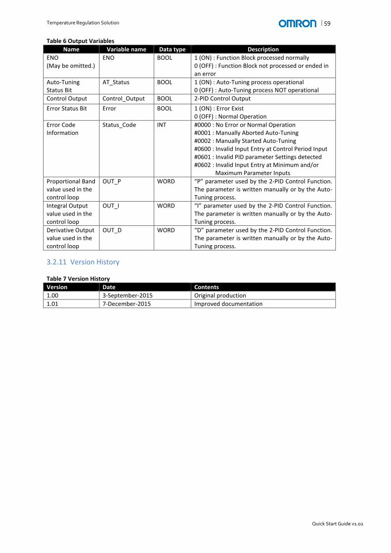
Table 6 Output Variables
Name Variable name Data type Description
ENO (May be omitted.)
ENO BOOL 1 (ON) : Function Block processed normally 0 (OFF) : Function Block not processed or ended in an error
Auto-Tuning Status Bit
AT_Status BOOL 1 (ON) : Auto-Tuning process operational 0 (OFF) : Auto-Tuning process NOT operational
Control Output Control_Output BOOL 2-PID Control Output
Error Status Bit Error BOOL 1 (ON) : Error Exist 0 (OFF) : Normal Operation
Error Code Information
Status_Code INT #0000 : No Error or Normal Operation #0001 : Manually Aborted Auto-Tuning #0002 : Manually Started Auto-Tuning #0600 : Invalid Input Entry at Control Period Input #0601 : Invalid PID parameter Settings detected #0602 : Invalid Input Entry at Minimum and/or Maximum Parameter Inputs
Proportional Band value used in the control loop
OUT_P WORD “P” parameter used by the 2-PID Control Function. The parameter is written manually or by the Auto-Tuning process.
Integral Output value used in the control loop
OUT_I WORD “I” parameter used by the 2-PID Control Function. The parameter is written manually or by the Auto-Tuning process.
Derivative Output value used in the control loop
OUT_D WORD “D” parameter used by the 2-PID Control Function. The parameter is written manually or by the Auto-Tuning process.
3.2.11 Version History Table 7 Version History
Version Date Contents
1.00 3-September-2015 Original production
1.01 7-December-2015 Improved documentation

60 | Temperature Regulation Solution
Quick Start Guide v1.02
3.3 System Configuration As mentioned in the previous section, the Compact CP1 PLC controls the Temperature Control process using the Temperature Control PID Function Block for the CP1W-TS Expansion Unit(s). Achieving communication between the Compact HMI and PLC is accomplished using various methods such as Serial and Ethernet. The first communication method is serial using RS-232, RS-485 or RS-422 with all NB HMI models. RS-232 is the most common serial connection and therefore this document only refers to the RS-232 method. RS-232 serial communication supports a 1:1 connection only. The CP1W-CIF01 option board supports RS-232 communications. The CP1E built-in port supports RS-232 communications. The second communication method is Ethernet related. The Ethernet configuration utilizes the CP1L-E with a built-in Ethernet port to achieve Ethernet communication with the NB HMI. Table 8 Communication Configurations illustrates what products are required to achieve specific configurations. Table 8 Communication Configurations
Serial Ethernet
NB__-TW00B Yes -
NB__-TW01B Yes Yes
CP1L-E Yes Yes
CP1W-CIF01 Yes -
CP1W-TS Yes Yes
The next sections contain the various communication configuration overviews.
Temperature Regulation Solution | 61
Quick Start Guide v1.02
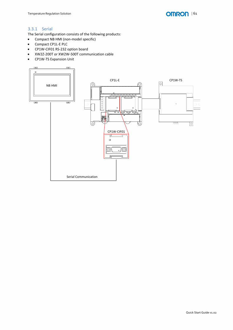
3.3.1 Serial The Serial configuration consists of the following products:
Compact NB HMI (non-model specific)
Compact CP1L-E PLC
CP1W-CIF01 RS-232 option board
XW2Z-200T or XW2W-500T communication cable
CP1W-TS Expansion Unit
NB HMI
CP1L-E
CP1W-CIF01
Serial Communication
CP1W-TS

62 | Temperature Regulation Solution
Quick Start Guide v1.02
3.3.2 Ethernet The Ethernet configuration consists of the following products:
Compact NB HMI (-TW01B model only)
Compact CP1L-E with built-in Ethernet Port PLC
CP1W-TS Expansion Unit
NB HMI
CP1L-E
Ethernet Communication
CP1W-TS

Temperature Regulation Solution | 63
Quick Start Guide v1.02
3.4 Communication Settings This chapter describes how to establish communication between the Compact NB HMI and Compact CP1 PLC using various methods.
3.4.1 HMI Connection Methods The following section describes how to setup Ethernet or Serial communication between the Compact NB HMI and CP1 PLC. Method 1: Serial As explained in section 3.3 System Configuration, serial communication is achieved using the CP1W-CIF01 RS-232 option board.
I. Configure the Compact CP1 PLC serial port using CX-Programmer as shown below.

64 | Temperature Regulation Solution
Quick Start Guide v1.02
I. Design the network configuration in NB-Designer as shown below.
II. Define the PLC Settings of PLC0:0

Temperature Regulation Solution | 65
Quick Start Guide v1.02
III. Define the NB HMI COM1 Settings

66 | Temperature Regulation Solution
Quick Start Guide v1.02
Method 2: Ethernet Ethernet communication is standard when using the Compact NB HMI–TW01B and the CP1L-E models. The Compact NB HMI–TW00B models do not support Ethernet communication. The following paragraphs illustrate how to configure the Ethernet Port settings.
I. Configure the Compact CP1 PLC built-in Ethernet port using CX-Programmer as shown below.

Temperature Regulation Solution | 67
Quick Start Guide v1.02
I. Design the network configuration in NB-Designer as shown below.
II. Define the PLC Settings.

68 | Temperature Regulation Solution
Quick Start Guide v1.02
III. Define the NB HMI Ethernet Port Settings.
IV. Define the Communication Settings.

Temperature Regulation Solution | 69
Quick Start Guide v1.02
REFERENCES H174-E1-06 E5_C Digital Temperature Controllers User’s Manual H175-E1-08 E5_C Digital Temperature Controllers Communications Manual H182-E1-01 E5CC / E5EC Solutions Guide for FAQs V106-E1-11 NB-Designer Operation Manual V107-E1-08 Setup Manual V108-E1-11 Host Connection Manual V109-E1-08 Startup Guide Manual W462-E1-08 CP1L CPU Unit Operation Manual W471-E1-07 CP1L CPU Unit Operation Manual W479-E1-08 CP1E CPU Unit Hardware User’s Manual W480-E1-07 CP1E CPU Unit Software User’s Manual W516-E1-02 CP1L-EL/EM CPU Unit Operation Manual

70 | Temperature Regulation Solution
Quick Start Guide v1.02
APPENDIX Appendix A: E5_C Hardware Information Appendix B: E5_C Communication Parameter Setup

Temperature Regulation Solution | 71
Quick Start Guide v1.02
Appendix A: E5_C Hardware Information
E5CC Temperature Controller The E5CC Temperature Controller supports On-Panel mounting. Please refer to manual H174-E1-06, section 2-1-3 Mounting, for more information how to mount the unit on a panel.
Model
Pin-out

72 | Temperature Regulation Solution
Quick Start Guide v1.02
Options Specification
The options specification of the E5CC is given in the following location (red symbols) within the model number.
𝐸5𝐶𝐶 −𝑀− The options code specifies additional features of the Temperature Controller, such as RS-485 communication.
Code Specifications Remarks
000 None
001 Event Inputs 1 and 2, and CT1
00214 Communications (R-485) and CT1
003 Communications (RS-485), CT1, and CT2
004 Communications (RS-485), and Event Inputs 3 and 4
005 Event Inputs 1 to 4
006 Event Inputs 1 and 2, and Transfer Output
Transfer Output: Current: 4 to 20 mA DC Voltage: 1 to 5 VDC
007 Event Inputs 1 and 2, and Remote SP Input
Remote SP Input: Current: 4 to 20 or 0 to 20 mA DC Voltage: 1 to 5, 0 to 5, or 0 to 10 VDC
Option codes 002, 003 and 004 support RS-485 communication. The pin-out overview shown in Figure 25 Options Specific Pin-out displays the pin out for the RS-485 communication.
Figure 25 Options Specific Pin-out
15
14
This model cannot be selected if 5 (screw terminals with cover) is selected for the terminal type. 15
Do not wire the grey terminals.

Temperature Regulation Solution | 73
Quick Start Guide v1.02
E5DC Temperature Controller The E5DC Temperature Controller support On-Panel and DIN-rail mounting. Please refer to manual H174-E1-06, section 2-1-3 Mounting, for more information how to mount the unit.
Model
Pin-out
74 | Temperature Regulation Solution
Quick Start Guide v1.02
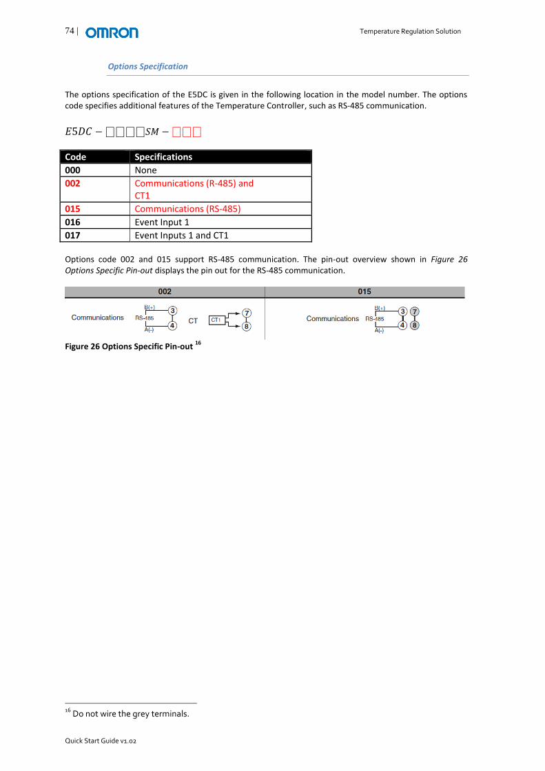
Options Specification
The options specification of the E5DC is given in the following location in the model number. The options code specifies additional features of the Temperature Controller, such as RS-485 communication.
𝐸5𝐷𝐶 −𝑆𝑀 −
Code Specifications
000 None
002 Communications (R-485) and CT1
015 Communications (RS-485)
016 Event Input 1
017 Event Inputs 1 and CT1 Options code 002 and 015 support RS-485 communication. The pin-out overview shown in Figure 26 Options Specific Pin-out displays the pin out for the RS-485 communication.
Figure 26 Options Specific Pin-out
16
16
Do not wire the grey terminals.
Temperature Regulation Solution | 75
Quick Start Guide v1.02
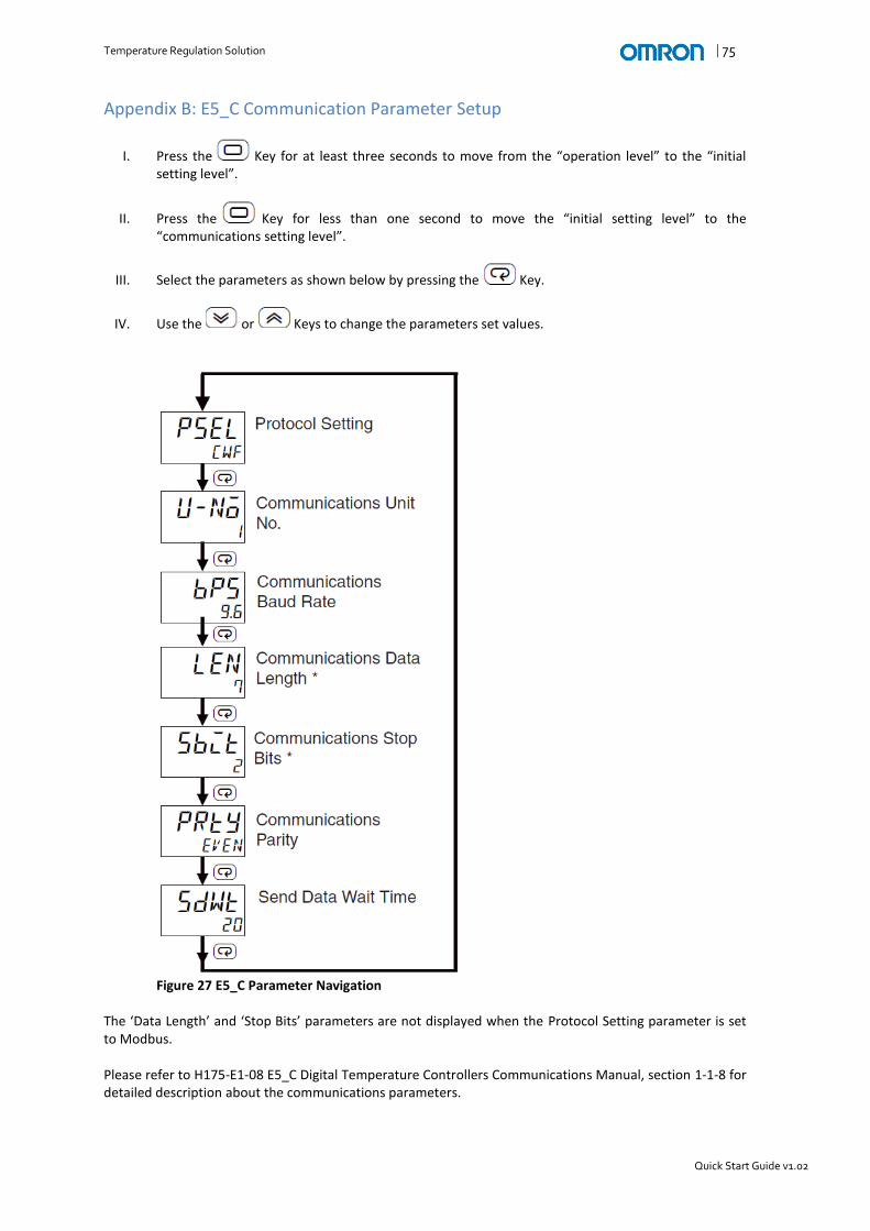
Appendix B: E5_C Communication Parameter Setup
I. Press the Key for at least three seconds to move from the “operation level” to the “initial setting level”.
II. Press the Key for less than one second to move the “initial setting level” to the “communications setting level”.
III. Select the parameters as shown below by pressing the Key.
IV. Use the or Keys to change the parameters set values.
Figure 27 E5_C Parameter Navigation
The ‘Data Length’ and ‘Stop Bits’ parameters are not displayed when the Protocol Setting parameter is set to Modbus. Please refer to H175-E1-08 E5_C Digital Temperature Controllers Communications Manual, section 1-1-8 for detailed description about the communications parameters.

76 | Temperature Regulation Solution
Quick Start Guide v1.02