tensional buckling around an elliptic hole in a stretched
TRANSCRIPT

epl draft
Tensional buckling around an elliptic hole in a stretched sheet
I. Andrade-Silva and M. Adda-Bedia
Universite de Lyon, Ecole Normale Superieure de Lyon, Universite Claude Bernard, CNRS, Laboratoire de Physique,F-69342 Lyon, France
PACS 46.32.+x – Static buckling and instabilityPACS 87.10.Pq – Elasticity theoryPACS 46.70.De – Beams, plates, and shells
Abstract – It is well known that an annular sheet could wrinkle as a result of axisymmetrictensile loads applied at the edges. In this system, regions under compression appear due toPoisson effect in the azimuthal direction yielding an incompatible excess in length, so that themembrane has to buckle out of the plane. Then, radial wrinkles emerge following the direction ofthe tensile principal stress. This so called Lame configuration has been widely used as theoreticaland experimental paradigms for wrinkling instabilities. In this work, we explore the consequencesof changing the geometry of this model configuration by considering an elliptic hole in an infinitestretched membrane. Using the Kolosoff-Inglis solution, we analyse the stress field around the holeand identify three possible regions: taut, unidirectionally tensioned and slack regions. Accordingto these definitions, we classify in a phase diagram the different stress states of the sheet asfunction of the hole eccentricity and of the applied tensions. Finally, we quantify how the tensionlines vary with the geometry of the hole and discuss possible outcomes on the emerging buckledpatterns.
Wrinkle and fold formation in elastic thin plates hasaroused a great interest due to its occurrence in a widerange of natural and manmade systems [1–9]. In bio-physics, particular attention has been paid in understand-ing traction forces involved in cell motility on elastic sub-strates using the emerging wrinkling patterns [2]. Formedical purposes, a better understanding of wrinkle for-mation would be helpful for the treatment of post-surgeryscars [1,6]. In condensed matter physics, pre-wrinkled con-ductive films have been proposed as stretchable electriccontacts [4] and wrinkles in graphene sheets are believedto modify its electronic properties [9]. Finally, examples ofwrinkled patterns are abundant in daily life: from clothesor curtains to human skin or fruit peels [6]. Wrinkles inthin elastic films emerge as a buckling instability due toin-plane compressive stresses. However, wrinkles can alsobe created when a sheet is subjected to a large enoughlongitudinal stretching yielding a transverse compressivestress due to the Poisson effect. In this case, the film buck-les to relax the in-plane strain incompatibility producingout-of-plane wavy deformations.
When wrinkling is induced by in-plane tension in mem-branes of zero flexural rigidity, the direction of wrinklesis described by tension field theory [10,11] which assumes
that the wrinkles occur along tension rays parallel to thedirection of the largest principal stress while the small-est principal stress collapses to zero. These assumptionsare supported by the fact that a plate with zero flexuralstiffness cannot sustain compressive stresses, the so-calledmembrane limit. Tension field theory has been applied topredict wrinkle directions in some specific geometries [12],however this theory, as it was formulated originally, is notable to predict the fine features of wrinkle patterns suchas their extension, wavelength and amplitude.
When the flexural stiffness is small but finite, one canidentify basically two regimes: a near-threshold (NT)regime which is just beyond the onset of buckling insta-bility [5] and a far-from-threshold (FFT) regime in whichthe wrinkles are well developed [7]. The NT regime can becharacterised by a perturbative analysis of the Foppl-vonKarman (FvK) equations over the flat state. Then, onecan derive scaling laws for the wavelength and extensionof the wrinkles. In the FFT regime, wrinkling induces acollapse of the stress component in the direction of com-pression [8]. Upon this assumption, the extension of thewrinkles and their wavelength are obtained by minimisingan energy functional. Thus, FFT analysis is a tension fieldtheory for membranes with finite flexural rigidity [8].
p-1
arX
iv:1
906.
0764
3v1
[co
nd-m
at.s
oft]
18
Jun
2019
I. Andrade-Silva M. Adda-Bedia
⌧Tout a
Tout
⇠ = ⇠0
⇠ ! 1
a�
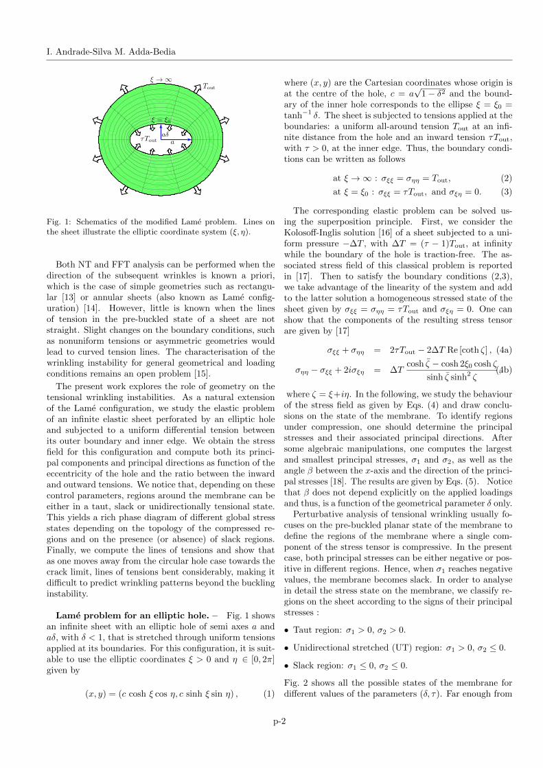
Fig. 1: Schematics of the modified Lame problem. Lines onthe sheet illustrate the elliptic coordinate system (ξ, η).
Both NT and FFT analysis can be performed when thedirection of the subsequent wrinkles is known a priori,which is the case of simple geometries such as rectangu-lar [13] or annular sheets (also known as Lame config-uration) [14]. However, little is known when the linesof tension in the pre-buckled state of a sheet are notstraight. Slight changes on the boundary conditions, suchas nonuniform tensions or asymmetric geometries wouldlead to curved tension lines. The characterisation of thewrinkling instability for general geometrical and loadingconditions remains an open problem [15].
The present work explores the role of geometry on thetensional wrinkling instabilities. As a natural extensionof the Lame configuration, we study the elastic problemof an infinite elastic sheet perforated by an elliptic holeand subjected to a uniform differential tension betweenits outer boundary and inner edge. We obtain the stressfield for this configuration and compute both its princi-pal components and principal directions as function of theeccentricity of the hole and the ratio between the inwardand outward tensions. We notice that, depending on thesecontrol parameters, regions around the membrane can beeither in a taut, slack or unidirectionally tensional state.This yields a rich phase diagram of different global stressstates depending on the topology of the compressed re-gions and on the presence (or absence) of slack regions.Finally, we compute the lines of tensions and show thatas one moves away from the circular hole case towards thecrack limit, lines of tensions bent considerably, making itdifficult to predict wrinkling patterns beyond the bucklinginstability.
Lame problem for an elliptic hole. – Fig. 1 showsan infinite sheet with an elliptic hole of semi axes a andaδ, with δ < 1, that is stretched through uniform tensionsapplied at its boundaries. For this configuration, it is suit-able to use the elliptic coordinates ξ > 0 and η ∈ [0, 2π]given by
(x, y) = (c cosh ξ cos η, c sinh ξ sin η) , (1)
where (x, y) are the Cartesian coordinates whose origin isat the centre of the hole, c = a
√1− δ2 and the bound-
ary of the inner hole corresponds to the ellipse ξ = ξ0 =tanh−1 δ. The sheet is subjected to tensions applied at theboundaries: a uniform all-around tension Tout at an infi-nite distance from the hole and an inward tension τTout,with τ > 0, at the inner edge. Thus, the boundary condi-tions can be written as follows
at ξ →∞ : σξξ = σηη = Tout, (2)
at ξ = ξ0 : σξξ = τTout, and σξη = 0. (3)
The corresponding elastic problem can be solved us-ing the superposition principle. First, we consider theKolosoff-Inglis solution [16] of a sheet subjected to a uni-form pressure −∆T , with ∆T = (τ − 1)Tout, at infinitywhile the boundary of the hole is traction-free. The as-sociated stress field of this classical problem is reportedin [17]. Then to satisfy the boundary conditions (2,3),we take advantage of the linearity of the system and addto the latter solution a homogeneous stressed state of thesheet given by σξξ = σηη = τTout and σξη = 0. One canshow that the components of the resulting stress tensorare given by [17]
σξξ + σηη = 2τTout − 2∆T Re [coth ζ] , (4a)
σηη − σξξ + 2iσξη = ∆Tcosh ζ − cosh 2ξ0 cosh ζ
sinh ζ sinh2 ζ,(4b)
where ζ = ξ+iη. In the following, we study the behaviourof the stress field as given by Eqs. (4) and draw conclu-sions on the state of the membrane. To identify regionsunder compression, one should determine the principalstresses and their associated principal directions. Aftersome algebraic manipulations, one computes the largestand smallest principal stresses, σ1 and σ2, as well as theangle β between the x-axis and the direction of the princi-pal stresses [18]. The results are given by Eqs. (5). Noticethat β does not depend explicitly on the applied loadingsand thus, is a function of the geometrical parameter δ only.
Perturbative analysis of tensional wrinkling usually fo-cuses on the pre-buckled planar state of the membrane todefine the regions of the membrane where a single com-ponent of the stress tensor is compressive. In the presentcase, both principal stresses can be either negative or pos-itive in different regions. Hence, when σ1 reaches negativevalues, the membrane becomes slack. In order to analysein detail the stress state on the membrane, we classify re-gions on the sheet according to the signs of their principalstresses :
• Taut region: σ1 > 0, σ2 > 0.
• Unidirectional stretched (UT) region: σ1 > 0, σ2 ≤ 0.
• Slack region: σ1 ≤ 0, σ2 ≤ 0.
Fig. 2 shows all the possible states of the membrane fordifferent values of the parameters (δ, τ). Far enough from
p-2

Tensional buckling around an elliptic hole in a stretched sheet
σ1,2 = τTout −∆T sinh 2ξ
cosh 2ξ − cos 2η± |∆T |
√(cosh 2ξ − cosh 2ξ0)2 sin2 2η + (cosh 2ξ0 − cos 2η)2 sinh2 2ξ
(cosh 2ξ − cos 2η)2, (5a)
tan 2β =(σξξ − σηη) sinh 2ξ sin 2η + 4σξη(sinh2 ξ − sin2 η)
2(σξξ − σηη)(sinh2 ξ − sin2 η)− 2σξη sinh 2ξ sin 2η, (5b)
Fig. 2: Representation of the six possible states of thestretched membrane, with taut, UT and slack regions. Thecorresponding values of the control parameters (δ, τ) are shownin each panel.
the hole, the sheet is always in a taut state. However,depending on the values of the control parameters, regionsof compressive stress(es) will appear around the hole. UTregions can either concentrate at the ends of the major axisof the elliptic hole or surround it entirely (as in the Lamecase). Slack regions can also appear as small ellipticalspots around the tips of the ellipse. A relevant questionfor a wrinkling stability analysis is whether the regionsunder compression that surround the hole are connectedor disconnected. According to Fig. 2, one can identify sixpossible global states that can characterised by the valuesof the principal stresses at some specific locations:
• S0: the entire sheet is taut: σ2(ξ0, η) > 0, ∀ η ∈ [0, 2π].
• S1: a single UT region surrounding the hole such thateach point at the edge is under compression: σ2(ξ0, η) <0, ∀ η ∈ [0, 2π] and σ1 > 0 everywhere.
• S2: there are two disconnected UT regions at both endsof the major axis of the hole, without slack regions:σ2(ξ0, 0) < 0 and σ2(ξ, π/2) > 0, ∀ξ ≥ ξ0.
• S2s: similar to S2 but with the presence of slack regionsaround the tips of the ellipse.
• S3: a single connected UT region around the ellipsewithout slack regions and with taut regions touching
��
��
��
���
��
���
��� ��� ��� ��� ��� ����
�
�
�
�
��
��
��
δ
τ
τ�(δ)
τ�(δ)
τ�(δ)
τ�(δ)
Fig. 3: Diagram showing the different states shown in Fig. 2in the parameter space (δ, τ). The critical curves τc(δ), τ1(δ),τ2(δ) and τs(δ) delimiting the different regions are defined inthe text.
both ends of the minor axis of the hole: σ2(ξ, π/2) ≤ 0 ina finite interval ξ0 < ξmin ≤ ξ ≤ ξmax and σ2(ξ, π/2) > 0elsewhere.
• S3s: similar to S3 but with the presence of slack regionsaround the tips of the ellipse.
Fig. 3 shows the phase diagram of these different states inthe parameter space (δ, τ). The critical separation curvescan be computed analytically as follows.
Due to the symmetries of the states shown in Fig. 2, thephase diagram can be retrieved by examining the principalstresses along η = 0 and η = π/2 only. Using Eqs. (5),one has for τ > 1
σ1,2(ξ, 0) = τTout −∆T coth ξ
[1∓ sinh2 ξ0
sinh2 ξ
], (6)
σ1,2(ξ, π/2) = τTout −∆T tanh ξ
[1∓ cosh2 ξ0
cosh2 ξ
].(7)
Recall that δ = tanh ξ0 and ∆T = (τ − 1)Tout. At theboundary of the hole, one has σ1(ξ0, 0) = σ1(ξ0, π/2) =τTout, while σ2(ξ0, 0) ≤ σ2(ξ0, π/2). Therefore, thethreshold of apparition of compressive stresses around thehole is given by σ2(ξ0, 0) < 0. Using Eq. (6), this condition
p-3

I. Andrade-Silva M. Adda-Bedia
yields
τ > τc(δ) =2
2− δ . (8)
The region S0 is defined by the condition τ < τc(δ) forwhich no compressive stresses occur. Notice that one re-covers the threshold τc(1) = 2 corresponding to the Lameproblem [7] and that τc(0) = 1 for a crack-like inter-face. Region S1 is characterised by the existence of acompressive region all around the hole. Thus the curveτ1(δ) bounding S1 is found by imposing the conditionσ2(ξ0, π/2) < 0. Using Eq. (7), we obtain
τ > τ1(δ) =2δ
2δ − 1. (9)
As expected from the Lame case, one has τ1(1) = τc(1) =2. Moreover, Eq. (9) shows that τ1 diverges as δ → 1/2.
To discriminate between the regions S2 [S2s] andS3 [S3s], one should explore the behaviour of σ2 alongthe y-axis. In these regions, one has σ2(ξ0, π/2) > 0 andσ2(∞, π/2) > 0 but σ2(ξ, π/2) may not be a monotonicfunction of ξ ≥ ξ0. The critical curve τ2(δ) separates aregion S2 [S2s] in which σ2(ξ, π/2) > 0 for all ξ ≥ ξ0 froma region S3 [S3s] where σ2(ξ, π/2) ≤ 0 in a finite intervalξ0 < ξmin ≤ ξ ≤ ξmax. The transition is given by lookingat a local minimum ξ∗ ≥ ξ0 such that
dσ2dξ
(ξ∗, π/2) = 0, (10)
σ2(ξ∗, π/2) = 0. (11)
Using Eq. (7), the condition (10) gives
ξ∗ = cosh−1√
3
1 + δ2. (12)
The solution given by Eq. (12) should satisfy ξ∗ ≥ ξ0.This condition holds for cosh ξ0 ≤
√2, which is equivalent
to require that δ ≤ δ∗ = 1/√
2. The curve τ2(δ) is foundby imposing condition (11). Using Eqs. (7,12) one finds
τ2(δ) =2√
3(2− δ2)3/2
2√
3(2− δ2)3/2 − 9(1− δ2), with 0 ≤ δ ≤ 1√
2.
(13)One can show that the curves τ2(δ) and τ1(δ) intersect at(δ∗ = 1/
√2, τ∗ = 2 +
√2). Hence, (δ∗, τ∗) corresponds to
a triple point in the phase diagram linking the states S1,S2 and S3 (see Fig. 3). Furthermore, notice that he slopesof τ1(δ) and τ2(δ) coincide at the triple point (τ ′2(δ∗) =τ ′1(δ∗)).
The critical curve τs(δ) defines the transition from thestates S2 and S3 to the states with slack regions S2s andS3s. As the slack regions concentrate close to the majoraxis of the elliptic hole (see Fig. 2), it is sufficient to inspectthe behaviour of σ1(ξ ≥ ξ0, 0) as given by Eq. (6). Usingthe same methodology as for the determination of τ2(δ),one finds that the curve τs(δ) is given by
τs(δ) =2√
3
2√
3− 9δ(1− δ2), with 0 ≤ δ < 1√
3. (14)
σ��(�)
����� �������������
������ �������������
���� ���� ���� ���� ���� ����-�
-�
-�
�
�
�/�
σ��(�)
�� ������ ������ ������-��
-��
-�
�
∼δ�
Fig. 4: Profile of σrr along the x-axis close to the hole forδ = 0.01 and τ = 1.1. The linear and crack approximationgiven by Eqs. (15,16) are also shown. The inset is a zoom inthe vicinity of the tip. The shaded area represents the regionwhere the crack approximation fails.
Eq. (14) shows that τs(δ) diverges as δ → 1/√
3 andτs(0) = τc(0) = 1. Therefore, slack regions occur whenthe elliptic hole is slender. This latter result motivates thestudy of the stretched membrane in the crack-like limit.
As δ → 0 the elliptic hole becomes slender and tendsto a straight cut of length 2a, resembling a crack in astretched membrane [19]. In this case the stress field closeto the elliptic hole is better represented in polar coordi-nates (r, θ) with origin r = 0 at the crack tip x = a. Weare interested in the asymptotic behaviour of the stressfield in the vicinity of the crack tip. In the appendix, weshow that the limits r → 0 and δ → 0 do not commute.
Let us first consider the asymptotic expansion of thestress field in powers of r/a for a given nonzero value ofδ. As one approaches the crack tip (r → 0) the radialstress component admits an expansion of the form (seethe appendix)
σrr(r, 0) = τTout −2∆T
δ3r
a+O
((r/a)2
). (15)
Notice that σrr(0, 0) = τTout, as dictated by the boundaryconditions. On the contrary, when one takes the cracklimit δ → 0 before performing the asymptotic expansion,the stress tensor admits an expansion of the form
σrr∣∣δ=0
(r, 0) = τTout −∆T√
2
√a
r+O
(√r/a). (16)
Excepting the term τTout, Eq. (16) corresponds to theasymptotic expansion of the radial stress component of astationary crack [20]. Notice that this expansion violatesthe original boundary conditions (3) at the hole. For smallδ 6= 0, the crack limit approximation looses validity as onemoves closer to the tip (see Fig. 4). The crack approxi-mation breaks down inside a cohesive zone-like region oftypical size rc. The radius rc can be estimated either as
p-4

Tensional buckling around an elliptic hole in a stretched sheet
δ = ��� δ = ��� δ = ��� δ = ��� δ = ���
Fig. 5: The lines of tension defined by the local principal stress directions given by Eq. (5b). Notice that the directions of thetension lines depend on the geometrical parameter δ only. Blue solid (resp. red dashed) lines correspond to the largest (resp.smallest) principal stress directions.
the radial distance at the intersection of the linear approx-imation (15) with the crack approximation (16) or as theradial distance of the local minimum of σ1(r, 0). The twocriteria yield rc ∼ aδ2 which coincides, up to proportion-ality factors, both with the radius of curvature at the tipof the elliptic hole and with the radius of convergence ofthe series expansions of the stress field given by Eqs. (A-2)in the appendix.
Discussion. – Fig. 3 shows the phase diagram ofthe different accessible global stress configurations of astretched sheet prior to any out-of-plane deformation. Torelease compressive stresses, a sheet with zero flexuralrigidity buckles as soon as τ > τc(δ), implying that thestates S3 and S3s of the phase diagram would not beaccessible. However, a sheet with finite flexural rigidityshould overcome a critical compressive stress to buckleand thus, one expects the whole phase diagram to be rel-evant. The present study shows that a slight deviationfrom the original Lame problem (a change of the geome-try of the perforated hole) gives rise to a phase diagramwith different global stress states that might induce a richvariety of wrinkled patterns. We believe our model prob-lem worths experimental studies to answer fundamentalquestions such as: Do wrinkled regions exhibit topologiessimilar to those of UT regions shown in Fig. 2? To whatextent the phase diagram computed in Fig. 3 remains rel-evant as τ is increased?
From a theoretical point of view, the difficulties of pre-dicting the state of the sheet beyond the pre-buckled oneare due to three main observations:
• UT regions exhibit complex, possibly disconnected, con-tours. Indeed, Fig. 3 shows that the Lame case δ = 1is peculiar as a small eccentricity modifies the nature ofthe transition to the wrinkled state. While for δ = 1 asingle symmetrical wrinkled state S1 exists, a new in-termediate state S2 (or S2s) emerges for δ 6= 1.
• The eccentricity of the hole may generate slack regionswhose effect on the post-wrinkling process is not docu-mented neither experimentally nor theoretically.
• The tension lines are not straight curving considerablyas the hole becomes slender (see Fig. 5). This featurehinders any prediction about the shape of wrinkles fromthe pre-buckled state.
These ascertainments prevent from performing classicalNT or FFT analysis. Due to the absence of axial sym-metry, it is not obvious how to perform a perturbationanalysis around the planar state or to find the regions ofthe sheet where only tensile forces take place. We believethat an accurate description of a general wrinkling prob-lem should be considered as a step-by-step dynamical-likeproblem, in the sense that once the membrane starts tobuckle, the stress landscape on the whole membrane ismodified and the buckled zones on the membrane are re-shaped accordingly. In our specific problem, for δ < 1 andτ & τc(δ), compressed regions occur mainly at the tips ofthe ellipse, consequently, the buckling instability will bepreferably located around the tips of the ellipse, much asa crack-like problem.
Specifically, wrinkles as wavy periodic structures couldbe peculiar patterns observed exclusively in symmetricconfigurations while the generic buckling instability wouldinduce in the first place folded patterns—localised out-of-plane excursions of the sheet separated by flat regionsunder pure tension [21]. This assumption opens alterna-tive approaches for the description of the post-bucklingbehaviour. For example, if one considers the folding mech-anism as a mean to suppress both normal and shear trac-tions along folds, one can envision the resulting patternas traction-free crack lines. In this sense, one expects thephysics underlying the selection of the folds pattern to beanalogous to that of cracks and then must be treated as adynamical process. The extension of a single fold shouldsatisfy the principle of local symmetry [22] and a Griffithenergy criterion [23] with vanishing fracture energy. Thus,the “equations of motion” of the fold can be written asKII = 0 and KI = 0, where KI (resp. KII) is the mode I(resp. mode II) stress intensity factor associated to thesquare root singularity of the stress field at the tip of thefold. These conditions ensure that the stress field in the
p-5

I. Andrade-Silva M. Adda-Bedia
periphery of the fold is shear-free and tensionless. Theproposed equations allow for predicting both the shapeand the extension of a single fold. In a realistic situationwith many folds, one should supplement the equations ofmotion of each fold with a global elastic energy functionalof the sheet, whose minimisation selects the geometricaland topological properties of the folding pattern.
Finally, we have studied the stress field in a sheet withan elliptic hole subjected to a differential tension betweenits inner and outer boundaries. We have found that re-gions around the hole can be either in a taut, slack orUT state. This yields a rich phase diagram of differentglobal stress states that should have an effect on the three-dimensional shape of the sheet beyond the buckling in-stability. These results demonstrate that slight geomet-rical asymmetries or inhomogeneous loading conditionsmight lead to complex wrinkled patterns. Our study callsfor experiments to probe the robustness of the wrinklingparadigm.
∗ ∗ ∗
I. A.-S. acknowledges the financial support of CONI-CYT DOCTORADO BECAS CHILE 2016-72170417.
REFERENCES
[1] Borges A. F., British Journal of Plastic Surgery, 13(1960) 47.
[2] Burton K., Park J. H. and Taylor D. L., MolecularBiology of the Cell, 10 (1999) 3745.
[3] Cerda E. and Mahadevan L., Physical Review Letters,90 (2003) 074302.
[4] Lacour S. P., Wagner S., Huang Z. and Suo Z., Ap-plied Physics Letters, 82 (2003) 2404.
[5] Geminard J.-C., Bernal R. and Melo F., The Eu-ropean Physical Journal E: Soft Matter and BiologicalPhysics, 15 (2004) 117.
[6] Cerda E., Journal of Biomechanics, 38 (2005) 1598.[7] Davidovitch B., Schroll R. D., Vella D., Adda-
Bedia M. and Cerda E. A., Proceedings of the NationalAcademy of Sciences, 108 (2011) 18227.
[8] Davidovitch B., Schroll R. and Cerda E., PhysicalReview E, 85 (2012) 066115.
[9] Deng S. and Berry V., Materials Today, 19 (2016) 197.[10] Reissner E., On tension field theory in proc. of The 5th
International Congress of Applied Mechanics 1938 pp. 88–92.
[11] Mansfield E. H., The Bending and Stretching of Plates(Cambridge University Press) 2005.
[12] Danielson D. and Natarajan S., Journal of Biome-chanics, 8 (1975) 135.
[13] Cerda E., Ravi-Chandar K. and Mahadevan L., Na-ture, 419 (2002) 579.
[14] Vella D., Adda-Bedia M. and Cerda E., Soft Matter,6 (2010) 5778.
[15] Aharoni H., Todorova D. V., Albarran O.,Goehring L., Kamien R. D. and Katifori E., NatureCommunications, 8 (2017) 15809.
[16] Inglis C. E., Transactions of the Institute of Naval Ar-chitects, 55 (1913) 219.
[17] Timoshenko S. and Goodier J. N., Theory of Elasticity(McGraw-Hill) 1969.
[18] Adda-Bedia M., Ben Amar M. and Pomeau Y., Phys-ical Review E, 54 (1996) 5774.
[19] Mahmood O., Audoly B. and Roux S., Physical ReviewLetters, 121 (2018) 144301.
[20] Williams M. L., Journal of Applied Mechanics, 28(1961) 78.
[21] King H., Schroll R. D., Davidovitch B. and MenonN., Proceedings of the National Academy of Sciences, 109(2012) 9716.
[22] Goldstein R. and Salganik R., International Journalof Fracture, 10 (1974) 507.
[23] Broberg K. B., Cracks and Fracture (Elsevier) 1999.
p-6
Tensional buckling around an elliptic hole in a stretched sheet
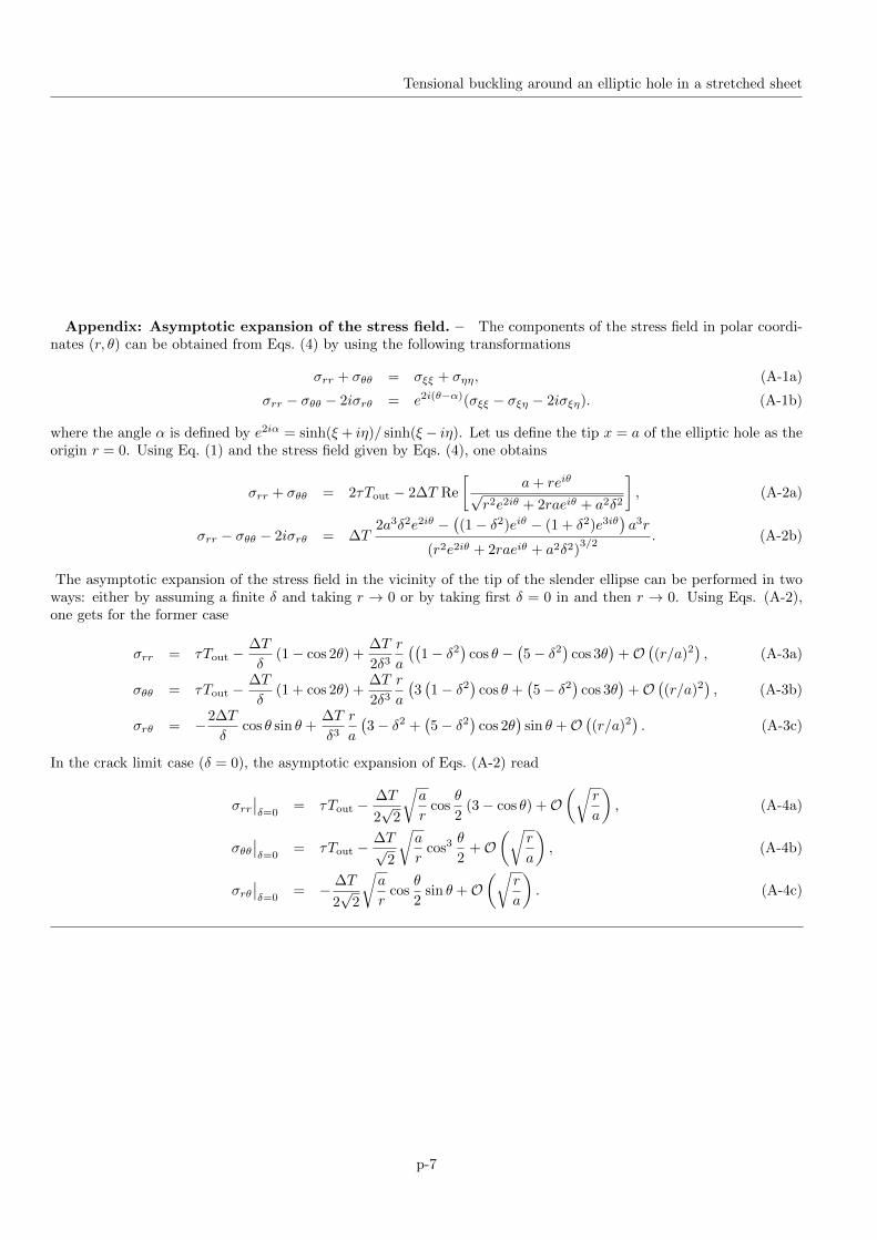
Appendix: Asymptotic expansion of the stress field. – The components of the stress field in polar coordi-nates (r, θ) can be obtained from Eqs. (4) by using the following transformations
σrr + σθθ = σξξ + σηη, (A-1a)
σrr − σθθ − 2iσrθ = e2i(θ−α)(σξξ − σξη − 2iσξη). (A-1b)
where the angle α is defined by e2iα = sinh(ξ + iη)/ sinh(ξ − iη). Let us define the tip x = a of the elliptic hole as theorigin r = 0. Using Eq. (1) and the stress field given by Eqs. (4), one obtains
σrr + σθθ = 2τTout − 2∆T Re
[a+ reiθ√
r2e2iθ + 2raeiθ + a2δ2
], (A-2a)
σrr − σθθ − 2iσrθ = ∆T2a3δ2e2iθ −
((1− δ2)eiθ − (1 + δ2)e3iθ
)a3r
(r2e2iθ + 2raeiθ + a2δ2)3/2
. (A-2b)
The asymptotic expansion of the stress field in the vicinity of the tip of the slender ellipse can be performed in twoways: either by assuming a finite δ and taking r → 0 or by taking first δ = 0 in and then r → 0. Using Eqs. (A-2),one gets for the former case
σrr = τTout −∆T
δ(1− cos 2θ) +
∆T
2δ3r
a
((1− δ2
)cos θ −
(5− δ2
)cos 3θ
)+O
((r/a)2
), (A-3a)
σθθ = τTout −∆T
δ(1 + cos 2θ) +
∆T
2δ3r
a
(3(1− δ2
)cos θ +
(5− δ2
)cos 3θ
)+O
((r/a)2
), (A-3b)
σrθ = −2∆T
δcos θ sin θ +
∆T
δ3r
a
(3− δ2 +
(5− δ2
)cos 2θ
)sin θ +O
((r/a)2
). (A-3c)
In the crack limit case (δ = 0), the asymptotic expansion of Eqs. (A-2) read
σrr∣∣δ=0
= τTout −∆T
2√
2
√a
rcos
θ
2(3− cos θ) +O
(√r
a
), (A-4a)
σθθ∣∣δ=0
= τTout −∆T√
2
√a
rcos3
θ
2+O
(√r
a
), (A-4b)
σrθ∣∣δ=0
= − ∆T
2√
2
√a
rcos
θ
2sin θ +O
(√r
a
). (A-4c)
p-7