tesla · the tesla m3 is capable for continuous monitoring of electrocardiogram (ecg), pulse...
TRANSCRIPT

Instructions for Use TeslaM3
MRI Patient Monitoring System All rights reserved – MIPM GmbH 2016 (English-Master-Version 3.1)
1
Instructions for Use
Version 3.1
TeslaM3
MRI Patient Monitoring System
0120
Instructions for Use TeslaM3
MRI Patient Monitoring System All rights reserved – MIPM GmbH 2016 (English-Master-Version 3.1)
2
MIPM Mammendorfer Institut für Physik und Medizin GmbH, herein after called MIPM.
Printed in Germany
Subject to change without prior notice. For further information contact MIPM.
It is possible that some features or functions described in this user manual are not available on your device.
Please contact MIPM or your local partner for further information.
All rights reserved to MIPM.
MIPM assume no responsibility for damages, which can result from using the monitor.
The monitor is intended for use by qualified medical personnel only.
Before using the monitor, read all the manuals that are provided with your device carefully. Patient monitoring
equipment, however sophisticated, should never be used as a substitute for the human care, attention, and critical
judgment that only trained health care professionals can provide.
NOTE: A note presents information that helps you operate the equipment or connected devices.
CAUTION: A caution provides information or instructions that must be followed to ensure proper
operation and performance of the equipment.
WARNING: A warning contains important information regarding possible danger to you or the
patient that is present during normal operation of the equipment.
The indicator refers to a possible action that can be performed by the user.
TeslaM3
operating system software from version: 2.00

Instructions for Use TeslaM3
MRI Patient Monitoring System All rights reserved – MIPM GmbH 2016 (English-Master-Version 3.1)
3
Chapter Overview
1. Overview ............................................................................................................ 9
2. Preparations for use ........................................................................................... 41
3. Monitor configuration ........................................................................................ 44
4. Patient Admission/Release ................................................................................. 60
5. Routine Use ...................................................................................................... 66
6. Trend and patient data transfer .......................................................................... 115
7. The Service Menu ........................................................................................... 119
8. Accessories and applied parts ........................................................................... 120
9. Cleaning and disinfection ................................................................................. 122
10. Trouble shooting ............................................................................................. 124
11. Technical specification .................................................................................... 125
12. Disposal ......................................................................................................... 138
13. Glossary ......................................................................................................... 138

Instructions for Use TeslaM3
MRI Patient Monitoring System All rights reserved – MIPM GmbH 2016 (English-Master-Version 3.1)
4
List of Contents
1. Overview ............................................................................................................ 9
1.1. Intended use............................................................................................................................... 9
1.2. General Safety Information ....................................................................................................... 10
1.3. Preliminary remarks for use ...................................................................................................... 11
1.4. Placement in the MRI Room ..................................................................................................... 14
1.5. Magnet Indicator TeslaSpy .......................................................................................................... 16
1.6. Reducing EMI ......................................................................................................................... 18
1.7. Electrical Safety ....................................................................................................................... 19
1.7.1. Electrostatic discharge (ESD) information .......................................................................... 19
1.7.2. ESD precautions to be taken .............................................................................................. 19
1.7.3. Electromagnetic compatibility and interference GUIDANCE ............................................... 20
1.7.4. Guidance and manufacturer's declaration - Electromagnetic Emissions Table 1 ..................... 21
1.7.5. Guidance and manufacturer's declaration - Electromagnetic Immunity Table 2 ...................... 22
1.7.6. Guidance and manufacturer's declaration - Electromagnetic Immunity Table 3 ...................... 23
1.7.7. Recommended separation distances between portable and mobile RF communication equipment
and TeslaM3 Table 4 ......................................................................................................................... 24
1.7.8. Electrical Safety ............................................................................................................... 25
1.8. Connecting external devices ...................................................................................................... 25
1.9. Safety, Inspections, Maintenance ............................................................................................... 27
1.10. Safety during HF surgery and defibrillation ................................................................................ 28
1.11. General Description .................................................................................................................. 29
1.12. Front and Back of the device ..................................................................................................... 30
1.12.1. Back of the device ............................................................................................................ 30
1.12.2. Front of the device ........................................................................................................... 32
1.13. Symbol Description .................................................................................................................. 33
1.13.1. Symbols in Graphical User Interface (GUI) ........................................................................ 33
1.13.2. Symbols on the Device ..................................................................................................... 36
1.14. The display .............................................................................................................................. 38
1.14.1. The menu bar ................................................................................................................... 38
1.14.2. Main screen ..................................................................................................................... 38
1.14.3. Status bar ......................................................................................................................... 38
1.15. Alarms .................................................................................................................................... 39
1.15.1. Technical Alarm............................................................................................................... 39
1.15.2. Parameter Alarm .............................................................................................................. 39
1.16. Touch screen and rotary knob .................................................................................................... 39
1.17. Documentation TeslaM3 ............................................................................................................. 40

Instructions for Use TeslaM3
MRI Patient Monitoring System All rights reserved – MIPM GmbH 2016 (English-Master-Version 3.1)
5
2. Preparations for use ........................................................................................... 41
2.1. General remarks ....................................................................................................................... 41
2.2. Initial Inspection ...................................................................................................................... 41
2.3. Default settings ........................................................................................................................ 42
2.4. Assembly and positioning of the TeslaM3 .................................................................................... 43
3. Monitor configuration ........................................................................................ 44
3.1. Initial setup .............................................................................................................................. 44
3.2. Battery power and Main power .................................................................................................. 44
3.2.1. Main unit ......................................................................................................................... 44
3.2.2. Wireless sensors ............................................................................................................... 45
3.2.3. Remote Screen ................................................................................................................. 45
3.3. Switching on the monitor .......................................................................................................... 45
3.4. Choosing the patient mode ........................................................................................................ 46
3.4.1. Free patient mode ............................................................................................................. 46
3.5. Main screen configuration ......................................................................................................... 46
3.5.1. Available parameters ........................................................................................................ 47
3.5.2. System configuration – The Options Menu ......................................................................... 47
3.5.3. Language ......................................................................................................................... 48
3.5.4. Date and Time ................................................................................................................. 49
3.5.5. Alarm function ................................................................................................................. 50
3.5.6. Perfusion Index (PI) ......................................................................................................... 51
3.5.7. Parameter settings ............................................................................................................ 52
3.5.8. Service Menu ................................................................................................................... 55
3.6. Monitor volume and Standby mode ........................................................................................... 56
3.7. Connecting Patient Sensors to the TeslaM3 .................................................................................. 56
3.7.1. The ECG sensor ............................................................................................................... 57
3.7.2. The SpO2 sensor .............................................................................................................. 57
3.7.3. NIBP tubes and cuffs ........................................................................................................ 58
3.7.4. IBP interface cable ........................................................................................................... 58
3.7.5. Gas sample lines and water traps ....................................................................................... 59
3.7.6. The temperature sensor ..................................................................................................... 59
4. Patient Admission/Release ................................................................................. 60
4.1. Patient Mode ........................................................................................................................... 60
4.1.1. Adult mode ...................................................................................................................... 61
4.1.2. Pediatric mode ................................................................................................................. 61
4.1.3. Neonatal mode ................................................................................................................. 61
4.1.4. Free patient mode ............................................................................................................. 61
Instructions for Use TeslaM3
MRI Patient Monitoring System All rights reserved – MIPM GmbH 2016 (English-Master-Version 3.1)
6
4.2. Patient admission ..................................................................................................................... 62
4.2.1. Enter patient data ............................................................................................................. 63
4.2.2. Utilization of patient data .................................................................................................. 64
4.3. Patient release .......................................................................................................................... 64
4.4. Connecting TeslaM3
to a hospital network (PDMS) ...................................................................... 65
5. Routine Use ...................................................................................................... 66
5.1. Switching on/off the monitor ..................................................................................................... 66
5.2. Switching on/off the Remote Monitor ........................................................................................ 67
5.3. Handling the wireless sensors .................................................................................................... 68
5.3.1. The ECG sensor ............................................................................................................... 69
5.3.2. The SpO2 sensor .............................................................................................................. 70
5.4. The main screen ....................................................................................................................... 71
5.5. Alarms .................................................................................................................................... 73
5.5.1. Battery alarms .................................................................................................................. 73
5.5.2. System Alarms ................................................................................................................. 74
5.5.3. Parameter Alarms ............................................................................................................. 75
5.5.4. Alarm priorities ................................................................................................................ 79
5.5.5. Activate and deactivate the alarm function ......................................................................... 79
5.5.6. Activate and deactivate single parameter alarms ................................................................. 80
5.5.7. Alarm silence and the adjust alarm function ........................................................................ 81
5.6. ECG and heart rate ................................................................................................................... 83
5.6.1. Remarks ECG during MRI examination ............................................................................. 84
5.6.2. ECG electrodes and skin preparation .................................................................................. 85
5.6.3. The ECG menu ................................................................................................................ 86
5.6.4. Setting the alarm limits ..................................................................................................... 87
5.6.5. Choosing the ECG lead ..................................................................................................... 87
5.6.6. Changing the ECG amplitude ............................................................................................ 88
5.6.7. ECG Cascade mode .......................................................................................................... 88
5.6.8. Choosing the pulse tone source .......................................................................................... 89
5.6.9. Cardiac Gating function .................................................................................................... 89
5.7. SpO2 Monitoring ..................................................................................................................... 90
5.7.1. Remarks SpO2 monitoring during MRI examination ........................................................... 91
5.7.2. Soft touch finger adapter – Placing the SpO2 sensor ............................................................ 92
5.7.3. The SpO2 menu ............................................................................................................... 94
5.7.4. Setting the alarm limits ..................................................................................................... 94
5.7.5. Changing the SpO2 scaling ............................................................................................... 94
5.7.6. Choosing the pulse tone source .......................................................................................... 95
5.7.7. The SpO2 gating function ................................................................................................. 95
Instructions for Use TeslaM3
MRI Patient Monitoring System All rights reserved – MIPM GmbH 2016 (English-Master-Version 3.1)
7
5.7.8. Perfusion index and signal inadequacy indicator ................................................................. 96
5.8. Noninvasive blood pressure (NIBP) ........................................................................................... 97
5.8.1. Remarks NIBP during MRI examination ............................................................................ 99
5.8.2. The NIBP menu ............................................................................................................... 99
5.8.3. Setting the alarm limits ..................................................................................................... 99
5.8.4. Setting the NIBP measurement interval ............................................................................ 100
5.8.5. Automatic / Manual measurements .................................................................................. 100
5.8.6. Operating steps .............................................................................................................. 101
5.9. Invasive blood pressure (IBP).................................................................................................. 101
5.9.1. Remarks IBP during MRI examination ............................................................................. 101
5.9.2. Use of IBP transducers ................................................................................................... 102
5.9.3. Connecting the IBP with the TeslaM3 ................................................................................ 103
5.9.4. The IBP menu ................................................................................................................ 103
5.9.5. Zeroing and calibration check .......................................................................................... 103
5.9.6. Setting the alarm limits ................................................................................................... 104
5.9.7. Changing the IBP scaling ................................................................................................ 104
5.10. Capnography ......................................................................................................................... 105
5.10.1. Adapting the sample rate ................................................................................................. 106
5.10.2. Installing / removing the water trap .................................................................................. 106
5.10.3. Connecting the sample gas line ........................................................................................ 106
5.10.4. The capnography menu ................................................................................................... 106
5.10.5. Setting the alarm limits ................................................................................................... 107
5.10.6. Changing the CO2 scaling ............................................................................................... 107
5.10.7. Setting the O2 Concentration ........................................................................................... 107
5.10.8. Setting the N2O Concentration ........................................................................................ 108
5.11. Multigas Module .................................................................................................................... 109
5.11.1. Warm Up ....................................................................................................................... 110
5.11.2. Installing/removing the water trap.................................................................................... 110
5.11.3. Connecting the sample gas lines ...................................................................................... 111
5.11.4. The Multigas menu ......................................................................................................... 111
5.11.5. Setting the alarm limits ................................................................................................... 112
5.11.6. Manual or automatic choice of the anesthetic agent ........................................................... 113
5.12. Temperature measurement ...................................................................................................... 113
5.12.1. Remarks Temperature Measurement during MRI examination: .......................................... 114
5.12.2. The Temperature menu ................................................................................................... 114
5.12.3. Setting the alarm limits ................................................................................................... 114
6. Trend and patient data transfer .......................................................................... 115
6.1. The Trend menu ..................................................................................................................... 115

Instructions for Use TeslaM3
MRI Patient Monitoring System All rights reserved – MIPM GmbH 2016 (English-Master-Version 3.1)
8
6.2. Graphical trends ..................................................................................................................... 116
6.3. Trend table ............................................................................................................................ 116
6.4. Event memory ....................................................................................................................... 117
6.5. Printing trend data .................................................................................................................. 117
6.6. Data transfer to a USB storage device ...................................................................................... 118
6.7. Deleting the trend memory ...................................................................................................... 118
7. The Service Menu ........................................................................................... 119
8. Accessories and applied parts ........................................................................... 120
8.1. ECG Accessories ................................................................................................................... 120
8.2. SpO2 Accessories .................................................................................................................. 120
8.3. NIBP Accessories .................................................................................................................. 120
8.4. IBP Accessories ..................................................................................................................... 120
8.5. Capnography Accessories ....................................................................................................... 121
8.6. Multigas Module Accessories .................................................................................................. 121
8.7. Temperature Accessories ........................................................................................................ 121
8.8. TeslaM3 Accessories .............................................................................................................. 121
9. Cleaning and disinfection ................................................................................. 122
9.1. Main unit and remote screen ................................................................................................... 122
9.2. Patient connection cables and wireless sensors .......................................................................... 122
9.3. NIBP cuffs............................................................................................................................. 122
9.4. Reusable pressure measurement accessories ............................................................................. 123
9.5. Multigas Module / Capnography module .................................................................................. 123
10. Trouble shooting ............................................................................................. 124
11. Technical specification .................................................................................... 125
12. Disposal ......................................................................................................... 138
13. Glossary ......................................................................................................... 138

Instructions for Use TeslaM3
MRI Patient Monitoring System All rights reserved – MIPM GmbH 2016 (English-Master-Version 3.1)
9
1. Overview
1.1. Intended use
The MRI Patient Monitoring System Tesla
M3 is intended for monitoring of vital signs during MRI
examinations (MRI procedures) of patients.
The Tesla
M3 is capable for continuous monitoring of Electrocardiogram (ECG), Pulse Oximetry (SpO2),
Non-Invasive Blood Pressure (NIBP), Invasive Blood Pressure (IBP), Temperature, Respiration,
Capnography (etCO2), Oxygen and Anesthetic Agents.
The Tesla M3
is intended for use by health care professionals.
Prescription:
In the USA, federal law restricts this device to sale by or on the order of a physician.
Contraindication:
The device is not designed to be used outdoors, in homecare, ambulances, helicopters, aircraft,
submarines, boats, hyperbaric chambers, explosive or flammable environment.

Instructions for Use TeslaM3
MRI Patient Monitoring System All rights reserved – MIPM GmbH 2016 (English-Master-Version 3.1)
10
1.2. General Safety Information
Read all operating instructions carefully before using the monitor. Specific warnings
and Cautions are found throughout the User Manual where they apply.
The Tesla M3 must only be used by qualified and trained medical staff.
In order to be trained, please contact MIPM or an authorized representative.
The TeslaM3
is intended for use in the same room as magnetic resonance equipment (MRI).
Use only batteries that are approved by MIPM (contact your local representative). The use of
non-approved batteries may damage the device.
NOTE: Lithium batteries have to be disposed according to the local regulations. In order to
prevent the danger of explosion or fire batteries should never be burned! MIPM is only
responsible for the safety of this device if:
a) maintenance, repairs, and modifications are carried out by authorized personnel,
b) if components are replaced with MIPM approved spare parts only and
c) the devices are used in accordance with MIPM Operating Instructions. A full technical
description is available upon request from your local MIPM representative.
The transport position for the TeslaM3
should be with the monitor ahead.

Instructions for Use TeslaM3
MRI Patient Monitoring System All rights reserved – MIPM GmbH 2016 (English-Master-Version 3.1)
11
1.3. Preliminary remarks for use
DANGER OF ELECTRIC SHOCK
Do not immerse the patient monitor in liquid. This may lead to electrocution.
Do not open the patient monitor.
Maintenance and repair of this unit must be performed by qualified and
authorized personnel only. Repairs should not be made by persons not
having knowledge and experience in the repair and security of this patient
monitor.
The product only fulfils the requirement written in the Documentation only if
the installation, handling as well as all maintenance, repair and service
works are in accordance with the instructions in this manual.
MIPM recommends to perform a function test and electrical safety test every
12 month. A technical control including calibration should be performed at
least every 24 month. Please refer to your national regulatory requirements.
A functional check should always be performed before using the monitor.
A damaged device may not be used! Missing parts or parts that are: broken,
worn out or contaminated have to be replaced. If a repair of the monitor is
necessary please contact your technical service, your local dealer or MIPM
directly.
This device, its components or accessories may only be repaired or
changed after MIPMs written approval.
The user is solely responsible for malfunctions that arise due to faulty
handling or maintenance as well as inadequate repair works or changes to
the device performed by unauthorized personnel.
The user shall not touch the monitor (accessible contacts of connectors,
contacts of fuse holders) and the patient simultaneously.
Caution:
To ensure patient safety, interference free performance of the TeslaM3
as well as
interference free MR images do only use original MIPM accessories that have
been especially developed for the use in the MRI environment. Other cables and
accessories may negatively affect also EMC performance.
Do not place the devices in direct vicinity to the magnetic centre of the scanner.
The TeslaM3
has to be positioned outside the magnetic field strength of 20
mT (200G)
The fiber optic part of the SpO2 Sensor consists of synthetic material and glass
fibres. There is no danger of heating or attraction to the MRI scanner.
Metal pigments in the colours used in the sensors may change the magnetic field
homogeneity in the examination area. Place the sensor outside of the examination
area
Do not open the sensors! Opening the sensors without proper training and
qualification destroys the RF shielding.
Reusable accessories with patient contact may be cleaned with regular
disinfection lotion or spray and dried with a soft tissue.

Instructions for Use TeslaM3
MRI Patient Monitoring System All rights reserved – MIPM GmbH 2016 (English-Master-Version 3.1)
12
Safety information, Warnings and general remarks
WARNING! DANGER OF EXPLOSION! Do not operate the monitor in
presence of flammable anesthetic mixtures with air, oxygen, or nitrous
oxide.
Do not use the monitor near devices with microwave or other high fre-
quency emissions that may interfere with the monitors operation. Excluded
is the use in MRI-environment.
Check parameter alarm limits before using the monitor
The TeslaM3
is intended only as an adjunct in patient assessment. It must be used in conjunction with assessment of clinical signs and symptoms.
The use of the TeslaM3
is restricted to one patient at a time.
If an alarm condition (other than the exceptions listed herein) occurs while the audible alarm mute function is engaged, only the visual alarm indications are displayed.
Do not silence an audible alarm, engage the audible alarm mute function, or decrease the audible alarm volume if patient safety could be compromised.
Blocking the speaker may result in an inaudible alarm tone.
Do not place the TeslaM3
in any position that might cause it, or any device connected to it, to fall on the patient or operator. Do not lift or carry the Tesla
M3 by the power supply cable.
Do only use MIPM accessories. Connect only items that have been specified in this manual as part of the Tesla M3 system or specified as being compatible with the Tesla M3 system.
All parts of the Equipment are not serviced or maintained while in use with the patient.
Do not touch simultaneously the monitor, monitor parts and a patient.
Do not position the equipment to make it difficult to operate the disconnection device from supply mains via unplugging the appliance coupler or mains plug.
In general for all parameters: The drop below the minimum amplitude or minimum value of patient physiological signal leads to inaccurate measurements. The measurement ranges derived from that are shown in Section 11, Technical Specification.
U.S. Federal and Canadian laws restrict this device to sale by or on the order of a li-
censed medical practitioner (Rx only)!
Do not place the TeslaM3
on electrical equipment that may disturb the TeslaM3
from working properly.
Do not expose the TeslaM3
to extreme moisture, such as direct exposure to
rain. Extreme moisture can cause the TeslaM3
to fail or perform inaccurately.
Do not place containers holding liquids on or near the TeslaM3
. Liquids spilled
on the TeslaM3
may cause it to perform inaccurately.
In the event the TeslaM3
is damaged and cannot be repaired, dispose of the
TeslaM3
through an approved hazardous materials disposal facility in
accordance with local regulations, or return it to MIPM or an authorized
distributor. The internal battery contains Lithium, which is hazardous waste.
The TeslaM3
may be operated during defibrillation but the parameter values may be
biased for a short period.

Instructions for Use TeslaM3
MRI Patient Monitoring System All rights reserved – MIPM GmbH 2016 (English-Master-Version 3.1)
13
TeslaM3
Power sources
The monitor can be operated with battery power or connected to line power inside the MRI room.
To avoid risk of electric shock, this equipment must only be connected to a supply
mains with protective earth.
Connect the TeslaM3
monitor only to a three-wire, grounded, hospital grade receptacle.
The three-conductor plug must be inserted into a properly installed three-wire receptacle.
If a three-wire receptacle is not available, a qualified electrician must install one in
accordance with the governing electrical code.
Do not under any circumstances remove the grounding conductor from the power plug.
Do not use extension cords, adapters or multiple socket-outlets of any type. Otherwise the
safety and function of the device can be disrupted. The power cord and plug must be
intact and undamaged.
If there is any doubt about the integrity of the protective earth conductor arrangement,
operate the TeslaM3
on internal battery power until the AC power supply protective
conductor is fully functional.
For questions please contact your local distributor or the manufacturer:
MIPM MAMMENDORFER INSTITUT FÜR PHYSIK UND MEDIZIN GMBH
Oskar-von-Miller Straße 6
82291 Mammendorf
GERMANY
Phone: +49 (8145) 9209-0
Fax: +49 (8145) 9209-33
www.mipm.com

Instructions for Use TeslaM3
MRI Patient Monitoring System All rights reserved – MIPM GmbH 2016 (English-Master-Version 3.1)
14
1.4. Placement in the MRI Room
The device may be operated at a maximum magnetic field strength of 20mT / 200G.
Depending on the different scanners this means a distance of approximately 1.5m / 5ft to the
opening of the bore (based on actively shielded 3T scanner).
For exact positioning of the monitor please use the integrated Magnet Indicator TeslaSpy
.
Do not place the TeslaM3
any closer than 1m / 4ft to the MRI scanner.
Observe the Signals of the TeslaSpy
(see next chapter).
Fix the position of the Monitor due to locking the brakes of castors.
MR Conditional

Instructions for Use TeslaM3
MRI Patient Monitoring System All rights reserved – MIPM GmbH 2016 (English-Master-Version 3.1)
15
Symbol Description
MR conditional (The device do not cause any hazard in a specified MR Environment) Magnetic Field: maximum 20 mT / 200 Gauss Distance to MR Scanner: minimum 1.5m
Caution! Observe the Magnet Indicator. Obligation for the user to consult the Instructions for use for important warnings and precautions
Lock the brakes of the four castors
Instructions for Use TeslaM3
MRI Patient Monitoring System All rights reserved – MIPM GmbH 2016 (English-Master-Version 3.1)
16
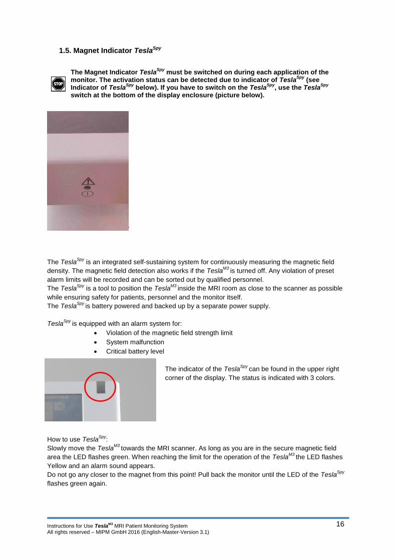
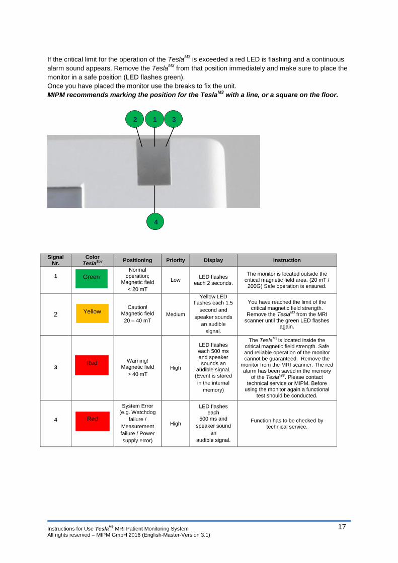
1.5. Magnet Indicator TeslaSpy
The Magnet Indicator TeslaSpy
must be switched on during each application of the monitor. The activation status can be detected due to indicator of Tesla
Spy (see
Indicator of TeslaSpy
below). If you have to switch on the TeslaSpy
, use the TeslaSpy
switch at the bottom of the display enclosure (picture below).
The TeslaSpy
is an integrated self-sustaining system for continuously measuring the magnetic field
density. The magnetic field detection also works if the TeslaM3
is turned off. Any violation of preset
alarm limits will be recorded and can be sorted out by qualified personnel.
The TeslaSpy
is a tool to position the TeslaM3
inside the MRI room as close to the scanner as possible
while ensuring safety for patients, personnel and the monitor itself.
The TeslaSpy
is battery powered and backed up by a separate power supply.
TeslaSpy
is equipped with an alarm system for:
Violation of the magnetic field strength limit
System malfunction
Critical battery level
The indicator of the TeslaSpy
can be found in the upper right
corner of the display. The status is indicated with 3 colors.
How to use TeslaSpy
:
Slowly move the TeslaM3
towards the MRI scanner. As long as you are in the secure magnetic field
area the LED flashes green. When reaching the limit for the operation of the TeslaM3
the LED flashes
Yellow and an alarm sound appears.
Do not go any closer to the magnet from this point! Pull back the monitor until the LED of the TeslaSpy
flashes green again.
Instructions for Use TeslaM3
MRI Patient Monitoring System All rights reserved – MIPM GmbH 2016 (English-Master-Version 3.1)
17
If the critical limit for the operation of the TeslaM3
is exceeded a red LED is flashing and a continuous
alarm sound appears. Remove the TeslaM3
from that position immediately and make sure to place the
monitor in a safe position (LED flashes green).
Once you have placed the monitor use the breaks to fix the unit.
MIPM recommends marking the position for the TeslaM3
with a line, or a square on the floor.
Signal
Nr. Color
TeslaSpy
Positioning Priority Display Instruction
1 Normal
operation; Magnetic field
< 20 mT
Low LED flashes
each 2 seconds.
The monitor is located outside the critical magnetic field area. (20 mT /
200G) Safe operation is ensured.
2 Caution!
Magnetic field
20 – 40 mT Medium
Yellow LED flashes each 1.5
second and
speaker sounds
an audible
signal.
You have reached the limit of the critical magnetic field strength.
Remove the TeslaM3
from the MRI scanner until the green LED flashes
again.
3
Warning! Magnetic field
> 40 mT High
LED flashes each 500 ms and speaker sounds an
audible signal. (Event is stored
in the internal
memory)
The TeslaM3
is located inside the critical magnetic field strength. Safe and reliable operation of the monitor cannot be guaranteed. Remove the
monitor from the MRI scanner. The red alarm has been saved in the memory
of the TeslaSpy
. Please contact technical service or MIPM. Before
using the monitor again a functional test should be conducted.
4
System Error (e.g. Watchdog
failure /
Measurement
failure / Power
supply error)
High
LED flashes each
500 ms and
speaker sound
an
audible signal.
Function has to be checked by technical service.
1 2 3
4
Green
Yellow
Red
Red
Instructions for Use TeslaM3
MRI Patient Monitoring System All rights reserved – MIPM GmbH 2016 (English-Master-Version 3.1)
18
1.6. Reducing EMI
To reduce possible problems caused by electromagnetic interference, we recommend the following:
Use only MIPM-approved accessories (See Section 8).
Use of other accessories may result in increased emissions or decreased immunity of
the TeslaM3
.
Ensure that other products used in areas where patient monitoring and/or life-support are
used comply with legal emissions standards. If the products are used inside the MRI room,
make sure that the products are labeled MRI conditional or MRI Safe.
Try to maximize the distance between TeslaM3
and other Wifi electro medical devices.
Strictly limit exposure and access to portable radio-frequency sources (e.g., cellular phones
and radio transmitters). Be aware that portable phones may periodically transmit even when in
standby mode.
Maintain good cable management. Do not route cables over electrical equipment. Do not inter-
twine cables.
Ensure all electrical maintenance is performed by qualified personnel.
The medical electrical equipment needs special precautions regarding EMC and needs to be
installed according to EMC information.
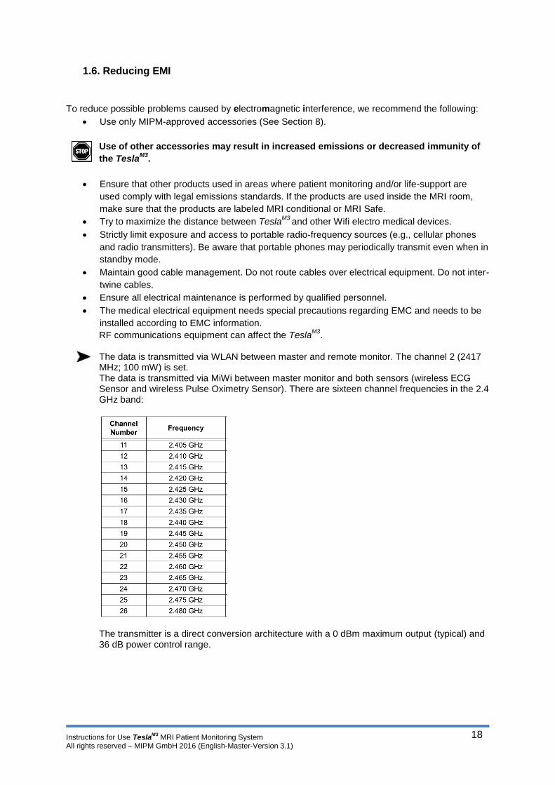
RF communications equipment can affect the TeslaM3
. The data is transmitted via WLAN between master and remote monitor. The channel 2 (2417 MHz; 100 mW) is set. The data is transmitted via MiWi between master monitor and both sensors (wireless ECG Sensor and wireless Pulse Oximetry Sensor). There are sixteen channel frequencies in the 2.4 GHz band:
The transmitter is a direct conversion architecture with a 0 dBm maximum output (typical) and 36 dB power control range.
Instructions for Use TeslaM3
MRI Patient Monitoring System All rights reserved – MIPM GmbH 2016 (English-Master-Version 3.1)
19
1.7. Electrical Safety
1.7.1. Electrostatic discharge (ESD) information
Warning:
Electronic components and semiconductors can be destroyed by electrostatic discharge (ESD). In particular, MOS components can be damaged from direct or indirect discharges. Damage caused by ESD is sometimes not immediately identifiable and malfunctions can even occur after a longer period of operation.
Exceeding and / or repeating the test level attained in guidance &
manufacturer's declaration on EMC may permanently damage the device and /
or cause serious malfunctions as loss of communication and system reboot.
Caution:
Connector panel symbol
All panel connector and communication ports are sensitive to electrostatic discharges; it is necessary to take precautions before touching connectors (pins or shield), connecting or disconnecting the associated cables.
Touching communication ports without taking ESD precautions may result in potential fatal error and ESD protection failure.
Points (e.g. screws) and surfaces that are only accessible for maintenance also require precautions.
Points (e.g. battery contacts for battery replacement) and surfaces that are accessible
only by intervention service users also require precautions.
1.7.2. ESD precautions to be taken
The following instructions related to electrostatic sensitive components (ESD standards) must be
observed: floor coatings made from wood, tiles and concrete, with relative humidity at least 40%.
If it is not possible to guarantee this environment, additional precautions must be taken, such as: use
of anti-static equipment, preliminary user discharge and wearing of anti-static clothes.
The best precaution is the preliminary user discharge on a metal ground such as a metal rail, metal
pole or metal part located at the rear of TeslaM3
.
For maintenance operation performed on TeslaM3
, the device must be placed on a conductive working
surface and the operator must wear a special ESD conductive wristband.
Instructions for Use TeslaM3
MRI Patient Monitoring System All rights reserved – MIPM GmbH 2016 (English-Master-Version 3.1)
20
1.7.3. Electromagnetic compatibility and interference GUIDANCE
Electromagnetic Compatibility
The MRI (MRI conditional) Patient Monitor TeslaM3
fulfills the following standards referring to creation and
inhibition of electromagnetic interferences: EN55011 and IEC60601-1-2.
TeslaM3
has been tested in accordance with the electromagnetic compatibility standards applicable to
medical devices. Its immunity is designed to ensure correct operation. Limitation of the emitted
radiation avoids undesirable interference with other equipment.
TeslaM3
is classified as a Class B device according to CISPR 11 emitted radiation and should not be
used outside the hospital environment. If used outside the hospital environment, this equipment might
not offer adequate protection to radio-frequency communication services. The user might be required
to take mitigation measures, such as relocating or re-orienting the equipment.
Use of accessories and cables other than those recommended by MIPM, could result in increased
emissions and / or decreased immunity of the TeslaM3
system.
If TeslaM3
is placed near devices such as HF surgical equipment, X-ray equipment, cell phones, DECT
phones or wireless access points, portable RFID reader, large scale RFID reader and RFID Tags, it is
essential to observe a minimum distance between the TeslaM3
and this equipment (refer to 'Table 4 -
Recommended separation distances between portable and mobile RF communication equipment and
TeslaM3
).
If TeslaM3
causes harmful interference or if it is itself disrupted, the user is encouraged to try to correct
the interference by one of the following actions:
Reorient or relocate the TeslaM3
or patient or disruptive equipment.
Change the routing of cables.
Separate power cables from the communication cables / signals.
Connect TeslaM3
mains plug on protected / backed-up / filtered supply or directly on UPS
circuit (uninterruptible power supply).
Be careful with ground / earth loops formed by communication cables and / or power
circuits: use class II powered systems or insulated bridges to break loops.
Maintain earth potential at the same level between TeslaM3
circuit and the circuit of the
remote equipment.
Increase the separation between the TeslaM3
and patient or disruptive equipment.
Connect the TeslaM3
into an outlet on a circuit different from that to which the patient or
disruptive equipment is connected.
In any case, whatever the context, the user should conduct interoperability testing in a
real situation to find the right setup and good location.
The TeslaM3
shall not be used adjacent to or stacked directly with other devices. If an
operation of the TeslaM3
stacked directly with or used adjacent to other devices is
required, the TeslaM3
should be observed to verify its proper operation used in this
arrangement.
The TeslaM3
may be interfered with by other equipment, even if that other equipment
complies with CISPR EMISSION requirements.

Instructions for Use TeslaM3
MRI Patient Monitoring System All rights reserved – MIPM GmbH 2016 (English-Master-Version 3.1)
21
1.7.4. Guidance and manufacturer's declaration - Electromagnetic Emissions
Table 1
The TeslaM3
system is intended to be used in the electromagnetic environment specified
below.
The customer or the user of the TeslaM3
system should ensure that it is used in such an
environment.
Table 1
Guidance and manufacturer's declaration – electromagnetic emissions
TeslaM3
is intended for use in the electromagnetic environment specified below. The customer or the user of the Tesla
M3 should assure that it is used in such an environment.
Emission measurements Agreement Electromagnetic Environment - Guidelines
RF emissions according CISPR 11
Group 1 TeslaM3
uses RF energy only for its internal function. Therefore, its RF emissions are very low and it is unlikely that nearby electronic equipment are interference.
RF emissions according CISPR 11
Class B The TeslaM3
is suitable for use in all establishments other than domestic and those directly connected to the public low voltage power supply network that supplies buildings used for domestic purposes.
Harmonic emissions IEC61000-3-2
Class A
Voltage fluctuations Flicker emissions IEC61000-3-3
complies

Instructions for Use TeslaM3
MRI Patient Monitoring System All rights reserved – MIPM GmbH 2016 (English-Master-Version 3.1)
22
1.7.5. Guidance and manufacturer's declaration - Electromagnetic Immunity Table 2
Table 2
Guidance and manufacturer's declaration - electromagnetic immunity
TeslaM3
is intended for use in the electromagnetic environment specified below. The customer or the user of the Tesla
M3 should assure that it is used in such an environment.
Immunity IEC 60601-Test level
Compliance level Electromagnetic Environment Guidelines
Electrostatic discharge (ESD) according IEC 61000-4-2
+/-6 kV contact discharge +/-8 kV air discharge
+/-6 kV contact discharge +/-8 kV air discharge
Floors should be wood, concrete or ceramic tile. If floors are covered with synthetic material, the relative humidity should be at least 30%.
Electrical fast transients (Burst) according IEC 61000-4-4
+/-2 kV for power lines +/-1 kV for input- and output lines
+/-2 kV for power lines +/-1 kV for input- and output lines
The quality of supply voltage should be that of a typical store or hospital environment.
Surge on AC power port according IEC 61000-4-5
+/-1 kV line to line +/-2 kV line to eath
+/-1 kV line to line +/-2 kV line to eath
The quality of supply voltage should be that of a typical store or hospital environment.
Voltage dips, short interruptions and voltage variations on power supply input lines according 61000-4-11
<5% UT (>95% reduction of UT) for 0.5 periods 40% UT (60% reduction of UT) for 5 periods 70% UT (30% reduction of UT) for 25 periods <5% UT (>95% reduction of UT) for 5s
<5% UT (>95% reduction of UT) for 0.5 periods 40% UT (60% reduction of UT) for 5 periods 70% UT (30% reduction of UT) for 25 periods <5% UT (>95% reduction of UT) for 5s
The quality of supply voltage should be that of a typical store or hospital environment. If the user of the Tesla
M3 requires
continued operation also at disruptions in energy supply, it is recommended to power the Tesla
M3
from an uninterruptible power supply or a battery.
Magnetic fields 50 Hz and 60 Hz according IEC 61000-4-8
3 A/m 3 A/m In case of picture problems, it may be necessary to place the Tesla
M3
farther away from the sources of power frequency magnetic fields or to install magnetic shielding: the Power frequency magnetic field should be measured at the designated site to ensure that it is sufficiently small.
NOTE: UT is AC mains voltage prior to application of the test level
Instructions for Use TeslaM3
MRI Patient Monitoring System All rights reserved – MIPM GmbH 2016 (English-Master-Version 3.1)
23
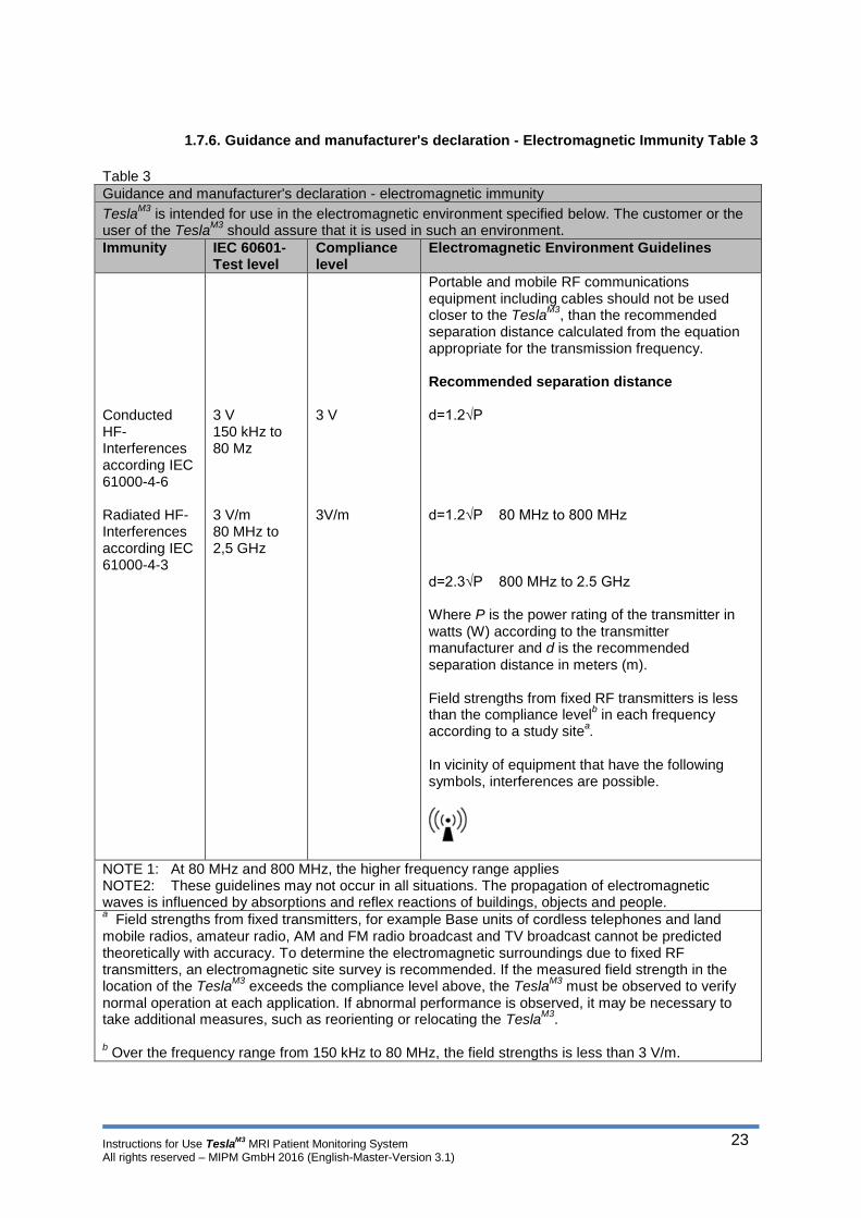
1.7.6. Guidance and manufacturer's declaration - Electromagnetic Immunity Table 3
Table 3
Guidance and manufacturer's declaration - electromagnetic immunity
TeslaM3
is intended for use in the electromagnetic environment specified below. The customer or the user of the Tesla
M3 should assure that it is used in such an environment.
Immunity IEC 60601-Test level
Compliance level
Electromagnetic Environment Guidelines
Conducted HF-Interferences according IEC 61000-4-6 Radiated HF-Interferences according IEC 61000-4-3
3 V 150 kHz to 80 Mz 3 V/m 80 MHz to 2,5 GHz
3 V 3V/m
Portable and mobile RF communications equipment including cables should not be used closer to the Tesla
M3, than the recommended
separation distance calculated from the equation appropriate for the transmission frequency. Recommended separation distance d=1.2√P d=1.2√P 80 MHz to 800 MHz d=2.3√P 800 MHz to 2.5 GHz Where P is the power rating of the transmitter in watts (W) according to the transmitter manufacturer and d is the recommended separation distance in meters (m). Field strengths from fixed RF transmitters is less than the compliance level
b in each frequency
according to a study sitea.
In vicinity of equipment that have the following symbols, interferences are possible.
NOTE 1: At 80 MHz and 800 MHz, the higher frequency range applies NOTE2: These guidelines may not occur in all situations. The propagation of electromagnetic waves is influenced by absorptions and reflex reactions of buildings, objects and people. a Field strengths from fixed transmitters, for example Base units of cordless telephones and land
mobile radios, amateur radio, AM and FM radio broadcast and TV broadcast cannot be predicted theoretically with accuracy. To determine the electromagnetic surroundings due to fixed RF transmitters, an electromagnetic site survey is recommended. If the measured field strength in the location of the Tesla
M3 exceeds the compliance level above, the Tesla
M3 must be observed to verify
normal operation at each application. If abnormal performance is observed, it may be necessary to take additional measures, such as reorienting or relocating the Tesla
M3.
b Over the frequency range from 150 kHz to 80 MHz, the field strengths is less than 3 V/m.
Instructions for Use TeslaM3
MRI Patient Monitoring System All rights reserved – MIPM GmbH 2016 (English-Master-Version 3.1)
24
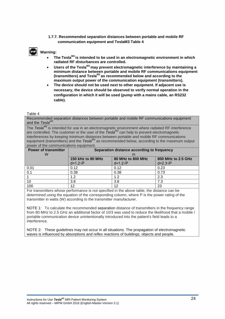
1.7.7. Recommended separation distances between portable and mobile RF
communication equipment and TeslaM3 Table 4
Warning:
The TeslaM3
is intended to be used in an electromagnetic environment in which radiated RF disturbances are controlled.
Users of the TeslaM3
may prevent electromagnetic interference by maintaining a minimum distance between portable and mobile RF communications equipment (transmitters) and Tesla
M3 as recommended below and according to the
maximum output power of the communication equipment (transmitters).
The device should not be used next to other equipment. If adjacent use is
necessary, the device should be observed to verify normal operation in the
configuration in which it will be used (pump with a mains cable, an RS232
cable).
Table 4
Recommended separation distances between portable and mobile RF communications equipment and the Tesla
M3
The TeslaM3
is intended for use in an electromagnetic environment where radiated RF interference are controlled. The customer or the user of the Tesla
M3 can help to prevent electromagnetic
interferences by keeping minimum distances between portable and mobile RF communications equipment (transmitters) and the Tesla
M3 as recommended below, according to the maximum output
power of the communications equipment.
Power of transmitter W
Separation distance according to frequency m
150 kHz to 80 MHz d=1.2√P
80 MHz to 800 MHz d=1.2√P
800 MHz to 2.5 GHz d=2.3√P
0.01 0.12 0.12 0.23
0.1 0.38 0.38 0.73
1 1.2 1.2 2.3
10 3.8 3.8 7.3
100 12 12 23
For transmitters whose performance is not specified in the above table, the distance can be determined using the equation of the corresponding column, where P is the power rating of the transmitter in watts (W) according to the transmitter manufacturer. NOTE 1: To calculate the recommended separation distance of transmitters in the frequency range from 80 MHz to 2.5 GHz an additional factor of 10/3 was used to reduce the likelihood that a mobile / portable communication device unintentionally introduced into the patient's field leads to a interference. NOTE 2: These guidelines may not occur in all situations. The propagation of electromagnetic waves is influenced by absorptions and reflex reactions of buildings, objects and people.

Instructions for Use TeslaM3
MRI Patient Monitoring System All rights reserved – MIPM GmbH 2016 (English-Master-Version 3.1)
25
1.7.8. Electrical Safety
Caution: The TeslaM3
including all connected devices may only be used in a clinical
environment fulfilling all regulatory requirements for electric installations.
The equipotentiality connection makes the connected equipment potential equal (ref.
IEC60601-1).
Symbol for equipotentiality connection:
Warning! The TeslaM3
is not approved for use inside rooms under explosion risk. If the
unit is operated near inflammable anesthetic agents there is a risk of explosion.
If the TeslaM3
is disconnected from main power the light of the charging indicator in the On/Off switch
disappears. The monitor automatically switches to battery power.
1.8. Connecting external devices
The TeslaM3
is equipped with interfaces to connect the following peripheral devices.
Interface Type Comment
USB Printer Brother HL-20 MIPM recommends to use the suggested printer.
USB pen drive Transcend 4GB MIPM recommends to use the suggested USB pen drive.
Ethernet Hospital Network PDMS
On request Individual adaption
Only available with remote screen. Network adaptation has to be performed by Network service provider.
RS232 Hospital network PDMS
On request Individual adaptation
Only available with remote screen. Network adaptation has to be performed by Network service provider.
RS232 optical data interface
On request Individual adaptation
Optical connection for Anesthesia View.

Instructions for Use TeslaM3
MRI Patient Monitoring System All rights reserved – MIPM GmbH 2016 (English-Master-Version 3.1)
26
Settings for peripheral devices can be changed in the Service Menu.
Do only use devices approved by MIPM. MIPM cannot guarantee complete functionality if
other devices are utilized.
Only certified devices according IEC 60950 can be connected.
Changing network and connectivity settings is reserved to personnel authorized by
MIPM.
The USB interface is intended to be used after the patient monitoring for e.g.
transferring the trend data to external devices or printing them.
Do not use the USB or connect any devices to USB interface of TeslaM3
during the
patient monitoring or in MRI room.
For more details ask your local distributor or MIPM.
Instructions for Use TeslaM3
MRI Patient Monitoring System All rights reserved – MIPM GmbH 2016 (English-Master-Version 3.1)
27
1.9. Safety, Inspections, Maintenance
WARNING: Because of the danger of electric shock, never remove the cover of any
device while in operation or connected to a power outlet.
In the interest of patient safety, regular equipment inspection and maintenance is required. Once a
year (every 12 month), check all cables, device, and accessories for damage, ground resistance,
chassis and patient leakage currents, and all alarm functions. Also, ensure that all safety labels are
legible. Maintain a record of these safety checks. For additional information, refer to the Service
Manual.
The NIBP measurement system has to be calibrated every 2 years (24 month).
A function test must be performed before each application of this device. Do not utilize this device if
known damage exists. Missing, broken, worn or soiled parts must be replaced before application. In
the event that repair or part replacement is necessary, please contact your local distributor, or MIPM.
This device, its components, and optional accessories may only be repaired or changed by authorized
and qualified service personnel. The user of this device is solely responsible for any failure of the
device to perform properly due to unauthorized and incorrect maintenance, incomplete repair, or dam-
age and changes made by unauthorized personnel.
Leakage current will increase when connecting multiple medical devices to a patient. Ensure the elec-
trical shock classification for each device is suitable for the intended application. MIPM recommends
that safety and functional checks be performed on the monitor at least once each year. The non-
invasive blood pressure circuits of the monitor should be calibrated at least every two years. These
checks should be performed by authorized personnel.
When main or battery power is not available, the monitor stores patient data and settings in an internal
battery backed-up SRAM.
The life span of the integrated battery depends on the number of charging cycles. After approximately
2 years you should expect a loss in battery capacity. This is typical for batteries and is considered as
regular wear out. In order to ensure maximum battery capacity MIPM recommends replacing the
batteries in the device and its sensors (ECG and SpO2) after 3 years of use.
CAUTION: To preserve the life of the internal battery, always leave the monitor connected to
main power when not in use. If the monitor is stored unconnected from line power, the
capacity of the internal battery will be drained in approximately three years.
Instructions for Use TeslaM3
MRI Patient Monitoring System All rights reserved – MIPM GmbH 2016 (English-Master-Version 3.1)
28
1.10. Safety during HF surgery and defibrillation
The monitor is protected against high-frequency interference from electro surgery units and discharges
from defibrillators, as well as against 50- and 60-Hertz power line interference.
The ECG recovery time after defibrillation is 1.5 seconds.
Only patient-related accessories including, electrodes as specified by the manufacturer
shall be used to guarantee defibrillator protection.
WARNING: The monitor is not protected against high-frequency interference from
diathermy equipment.
When TeslaM3
is used with HF surgical equipment, parts of the equipment must be
proved with protection against burning of the patient.
CAUTION: During Electro surgery, observe the following guidelines to minimize ESU
interference and provide maximum user and patient safety:
Keep all transducers and intermediate cables off of earth ground and away from
the ESU knife and return wires.
Use the SpO2 pulse rate instead of the ECG to determine the heart rate.
Do only use accessories approved for High Frequency areas.

Instructions for Use TeslaM3
MRI Patient Monitoring System All rights reserved – MIPM GmbH 2016 (English-Master-Version 3.1)
29
1.11. General Description
The MRI Patient monitoring system TeslaM3
ensures high quality vital signs monitoring for adult,
pediatric and neonatal patients during MRI examinations.
Monitoring parameter:
ECG and heart rate
Pulse oximetry
Non-invasive blood pressure
Invasive blood pressure (2x)
Capnography
Anesthetic Agents (Auto Detection)
Body temperature (2x)
Data management:
Trend memory
Event Memory
Patient data
Network (only with Remote Monitor)
Printer, USB connectivity
TeslaM3
is equipped with a 15’’ color touch display. The optional wireless remote monitor offers
complete functionality in the MRI control room.
The monitor is equipped with a rechargeable battery (see the technical specs section in the user manual for more details). The IEC socket enables the connection of the monitor to the hospital electricity network.

Instructions for Use TeslaM3
MRI Patient Monitoring System All rights reserved – MIPM GmbH 2016 (English-Master-Version 3.1)
30
1.12. Front and Back of the device
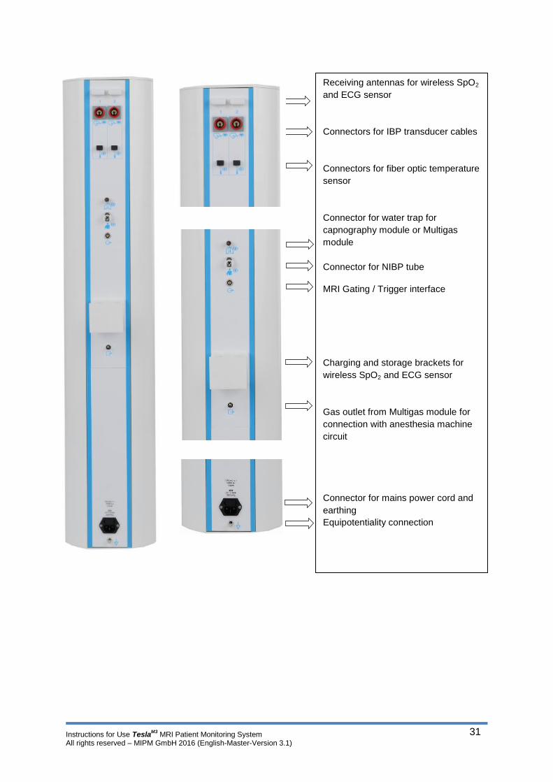
1.12.1. Back of the device
Instructions for Use TeslaM3
MRI Patient Monitoring System All rights reserved – MIPM GmbH 2016 (English-Master-Version 3.1)
31
Receiving antennas for wireless SpO2
and ECG sensor
Connectors for IBP transducer cables
Connectors for fiber optic temperature
sensor
Connector for water trap for
capnography module or Multigas
module
Connector for NIBP tube
MRI Gating / Trigger interface
Charging and storage brackets for
wireless SpO2 and ECG sensor
Gas outlet from Multigas module for
connection with anesthesia machine
circuit
Connector for mains power cord and
earthing
Equipotentiality connection
Instructions for Use TeslaM3
MRI Patient Monitoring System All rights reserved – MIPM GmbH 2016 (English-Master-Version 3.1)
32
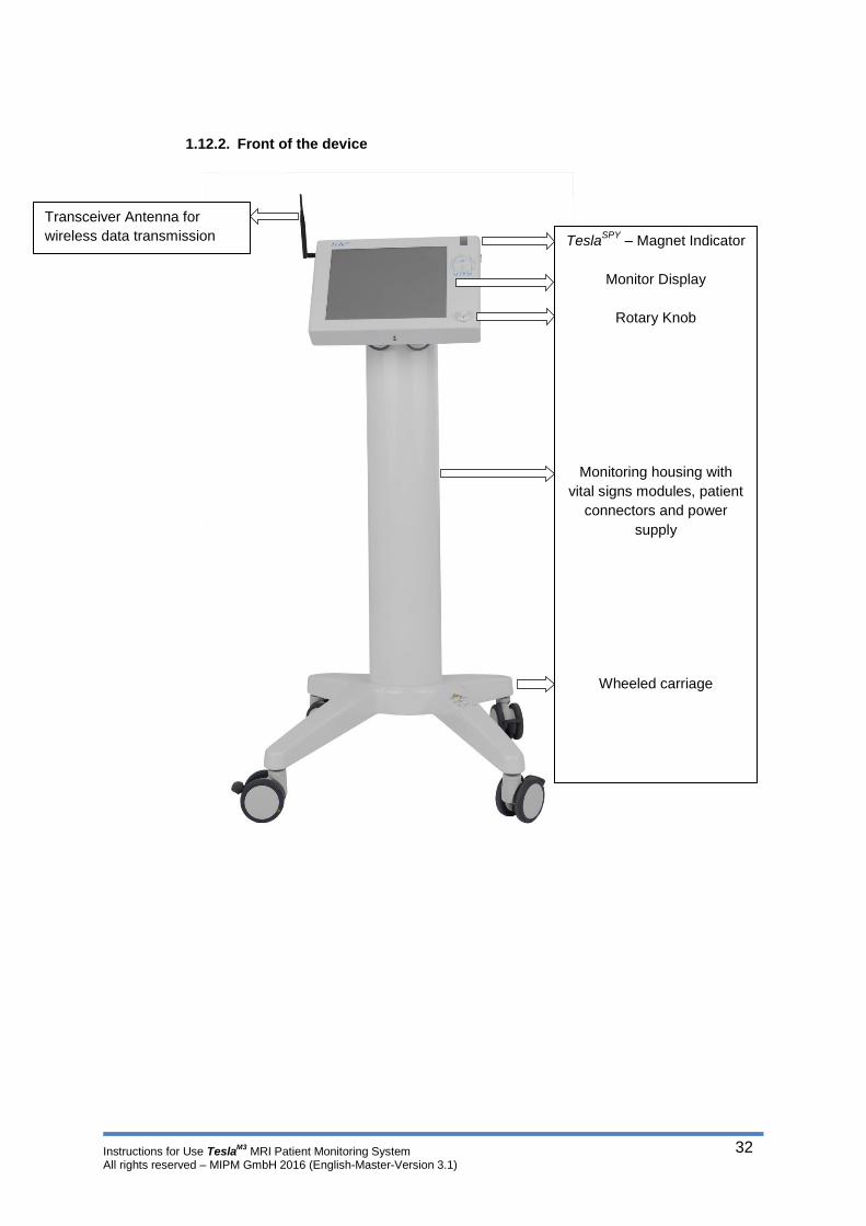
1.12.2. Front of the device
TeslaSPY
– Magnet Indicator
Monitor Display
Rotary Knob
Monitoring housing with
vital signs modules, patient
connectors and power
supply
Wheeled carriage
Transceiver Antenna for
wireless data transmission

Instructions for Use TeslaM3
MRI Patient Monitoring System All rights reserved – MIPM GmbH 2016 (English-Master-Version 3.1)
33
1.13. Symbol Description
1.13.1. Symbols in Graphical User Interface (GUI)
Status bar
Symbol Definition
Connection status Remote Monitor
Connection status Master Monitor
Connection and Battery status ECG sensor
Connection and Battery status SpO2 sensor
Battery level main unit
Description field for text messages
Menu bar
Symbol Definition
Patient mode
Main screen
Option Menu
Patient data menu
Trend menu
Patient Mode
Symbol Definition
Adult mode
Pediatric mode
Neonatal mode
Individual configuration
Turn off Tesla
M3

Instructions for Use TeslaM3
MRI Patient Monitoring System All rights reserved – MIPM GmbH 2016 (English-Master-Version 3.1)
34
Main screen
Symbol Definition
Duration NIBP interval
Start/Stop manual NIBP measurement
Alarm Silence within 120 seconds
Alarm Reset
Standby
Volume
Alarm function of the monitor is deactivated
Single parameter alarm deactivated
Adjust alarm function
+ / - Icon
ECG sensor connection alarm
SpO2 sensor connection alarm
ECG Lead Off alarm
SpO2 finger not in sensor alarm
“Back“ / „Next“ Icon – to browse between menus
Enter
Status of alarm silence
(within 120 sec.)
Switching between large and small figures for parameter
values

Instructions for Use TeslaM3
MRI Patient Monitoring System All rights reserved – MIPM GmbH 2016 (English-Master-Version 3.1)
35
Option Menu
Symbol Definition
Choose time format 12/24h
Save changes
„Ping“ Icon for connectivity check
Trend Menu
Symbol Definition
Graphical trend memory
Tabular trend memory
Event memory
Delete trend memory
Send data to printer
Send data to USB storage device

Instructions for Use TeslaM3
MRI Patient Monitoring System All rights reserved – MIPM GmbH 2016 (English-Master-Version 3.1)
36
1.13.2. Symbols on the Device
Rear Panel
Symbol Definition
Protection against leakage current;
Defibrillation-proof type CF applied part
Protection against leakage current;
Defibrillation-proof type CF applied part
Invasive blood pressure (IBP1 and IBP2)
Protection against leakage current;
Defibrillation-proof type CF applied part
Body Temperature (Temp. 1 and Temp. 2)
Protection against leakage current;
Defibrillation-proof type BF
Respiration
Protection against leakage current;
Defibrillation-proof type BF
Non-invasive blood pressure (NIBP)
Protection against leakage current;
Defibrillation-proof type BF
MRI Gating / Trigger interface
Gas outlet
Equipotentiality connection
Electrical fuses
Alternating Current (AC)
Instructions for Use TeslaM3
MRI Patient Monitoring System All rights reserved – MIPM GmbH 2016 (English-Master-Version 3.1)
37
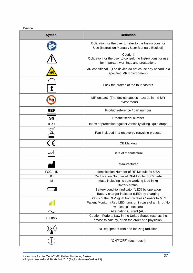
Device
Symbol Definition
Obligation for the user to refer to the Instructions for
Use (Instruction Manual / User Manual / Booklet)
Caution! Obligation for the user to consult the Instructions for use
for important warnings and precautions
MR conditional: (The device do not cause any hazard in a
specified MR Environment)
Lock the brakes of the four castors
MR unsafe: (The device causes hazards in the MR
Environment)
Product reference / part number
Product serial number
IPX1 Index of protection against vertically falling liquid drops
Part included in a recovery / recycling process
CE Marking
Date of manufacture
Manufacturer
FCC – ID Identification Number of RF-Module for USA
IC Certification Number of RF-Module for Canada
M Mass including its safe working load in kg
Battery status:
Battery condition indicator (LED) by operation
Battery charger indicator (LED) by charging
Status of the RF-Signal from wireless Sensor to MRI
Patient Monitor. (Red LED turns on in case of an Error/No
wireless connection)
Alternating Current (AC)
Rx only Caution: Federal Law in the United States restricts the
device to sale by, or on the order of a physician.
RF equipment with non-ionizing radiation
“ON”/“OFF” (push-push)

Instructions for Use TeslaM3
MRI Patient Monitoring System All rights reserved – MIPM GmbH 2016 (English-Master-Version 3.1)
38
1.14. The display
1.14.1. The menu bar
1.14.2. Main screen
1.14.3. Status bar
Patient mode tab Choice of patient mode and indication
which patient mode is in use
Main screen tab Display of all vital signs during regular
operation
Option Menu tab Settings
Patient data tab Patient admission and patient release
Trend menu tab Graphical, tabular and event memory,
data export and printer
All vital signs are displayed
in the main screen.
Up to 6 channels can be
displayed at the same time.
In the upper part of the
main screen you will find
the status bar.
The function icons are at
the bottom of the main
screen.
Window for alarm text messages
Status of main unit, sensor connectivity and battery status and time
Instructions for Use TeslaM3
MRI Patient Monitoring System All rights reserved – MIPM GmbH 2016 (English-Master-Version 3.1)
39
1.15. Alarms
TeslaM3
signals acoustic as well as optical alarms. Here the monitor distinguishes between technical
(System) alarms and parameter alarms.
Alarms are automatically prioritized according to urgency and degree of exposure for the patient. If
several alarms occur simultaneously the events will be displayed on the main screen according to the
respective priority.
If several alarms with equal priority occur simultaneously the respective alarm messages rotate in the
text window in the status bar.
1.15.1. Technical Alarm
Technical alarms concern the basic functionality of the monitor and the different components.
Technical alarms are displayed directly in the main screen (e.g. sensor connection alarm) or as a text
message in the status bar (e.g. battery alarm).
1.15.2. Parameter Alarm
Parameter alarms are activated if the upper or lower alarm limit of a vital sign is violated. A parameter
alarm will be displayed in the parameter box of the respective vital sign in the main screen. Parameter
alarms are automatically deactivated if the reading of the respective vital sign is back to the accepted
values. Users may confirm, deactivate, or adjust parameter alarms.
1.16. Touch screen and rotary knob
The TeslaM3
is equipped with two independent controls. Any setting on the monitor may be performed
via Touch screen or using the rotary knob. In both cases the user has full functionality of the monitor.
In order to use the touch screen the user has to push the respective icons and menus directly on the
display.
If the rotary knob is used a cursor appears on the display. This cursor can be moved to any position or
menu on the display. The rotary knob may be used clockwise or anti-clockwise. The cursors direction
of rotation coincides with the rotation of the rotary knob. In order to activate an icon or enter a menu,
press the rotary knob.
Note: If the Touch screen functionality is disabled due to malfunction of the display use the
rotary knob as alternative monitor control.
Instructions for Use TeslaM3
MRI Patient Monitoring System All rights reserved – MIPM GmbH 2016 (English-Master-Version 3.1)
40
1.17. Documentation TeslaM3
Documentation Set
The TeslaM3
documentation set consists of documents for the clinician, the biomedical technician and
the department head or purchaser of the TeslaM3
monitor, and accessories.
This TeslaM3
instruction manual contains important safety and operating information for the clinician.
Statement of Expectations to the Reader
This instruction manual was written for the clinician. Although this manual may describe some
monitoring techniques, Mammendorfer Institut für Physik und Medizin expects you to be a trained
clinician who knows how to take and interpret a patient’s vital signs during Magnetic Resonance
Imaging. The TeslaM3
has been designed as a quality monitor; however, inherent limitations require
that good clinical judgment always prevail.
Disclaimers
Mammendorfer Institut für Physik und Medizin cautions the reader of this manual:
This manual and product specifications may, wholly or partially, be subject to change without
notice. Some features described in this manual may not be available on your model.
All rights are reserved: No one is permitted to reproduce or duplicate, in any form, the whole
or part of this manual without Mammendorfer Institut für Physik und Medizin’s permission.
Mammendorfer Institut für Physik und Medizin assumes no responsibility for any damage that
may occur due to accidents while using this system.
Instructions for Use TeslaM3
MRI Patient Monitoring System All rights reserved – MIPM GmbH 2016 (English-Master-Version 3.1)
41
2. Preparations for use
2.1. General remarks
Warning: Before monitoring pediatrics or neonates, please keep in mind:
Chose the correct size of finger adapter for SpO2 monitoring
Chose the correct size of NIBP cuff for the patients size
Change the patient mode to pediatric or neonatal
Caution: Do only use accessories delivered and approved by MIPM. Accessories that
are not approved by MIPM may lead to incorrect monitoring values or malfunctioning
of the monitor.
2.2. Initial Inspection
1. Unpack and inspect the monitor TeslaM3
and the wireless pulse oximetry sensor for external
damage. Verify that all connectors and fasteners are securely in place.
2. Inspect the wireless pulse oximetry sensor for breaking points or visible damages. Remove
the transport plugs from the wireless sensors.
3. Connect the TeslaM3
to main power. Insert the wireless sensors in the charging set and see if
the battery is charged. The battery LED on sensor is flashing. (To see how the sensor is
placed in the charging set see section 5 Handling of the Wireless sensors)
4. Check the silicon finger adapters for visible damage. 5. Switch on the Tesla
M3 using the main switch at the right side of the display.
6. Choose a patient mode by pressing on one of the icons on the patient mode screen. The main screen is displayed. (If the sensors are in the charging bracket you will see the sensor connection alarm).
7. If the TeslaM3
is connected to main power you will see the “Battery is charged” symbol in the
status bar. ( )
8. Unplug the TeslaM3
and check if the “Battery” symbol appears. ( ) 9. Remove the SpO2 sensor from the charging bracket. The sensor automatically turns on and
performs a self-test. If a technical problem in the sensor is detected the red malfunction LED flashes. If the self-test is passed the sensor will automatically connect to the main unit and the sensor connection alarm disappears. The sensor status symbol is displayed in the status bar.
( ) 10. Remove the ECG sensor from the charging bracket. The sensor automatically turns on and
performs a self-test. If a technical problem in the sensor is detected the red malfunction LED flashes. If the self-test is passed the sensor will automatically connect to the main unit and the sensor connection alarm disappears. The sensor status symbol is displayed in the status bar.
( )

Instructions for Use TeslaM3
MRI Patient Monitoring System All rights reserved – MIPM GmbH 2016 (English-Master-Version 3.1)
42
2.3. Default settings
The software language of the TeslaM3
will be English at delivery. If you want to choose another
language please see the Language section below.
System Time and Date
Before using the TeslaM3
please check if the system time and date are correct. To change the time
and date follow the steps below:
1. Switch on the TeslaM3
.
2. Chose the Options menu on the menu bar ( )
3. Press the Date / Time icon.
4. Set date and time (hour : minute ; day : month : year) (See section 3 “Monitor configuration”
for further instructions)
5. Press the Back icon to leave the date / time menu.
Language settings:
1. Switch on the TeslaM3
.
2. Chose the Options menu on the menu bar ( )
3. Chose the Service menu (password protected!)
4. Press the language icon.
5. Chose the desired language
6. Press the Back icon to leave the language menu.
Audio Setup
1. Switch on the TeslaM3
2. Chose the main screen in the menu bar. ( )
3. Press the Volume Icon in the lower right corner of the display
Choose the volume for alarm and pulse tone sound by pressing the desired volume level bar.
(See section 3 “Monitor configuration” for further instructions)
4. Press the Back icon to leave the volume menu.

Instructions for Use TeslaM3
MRI Patient Monitoring System All rights reserved – MIPM GmbH 2016 (English-Master-Version 3.1)
43
2.4. Assembly and positioning of the TeslaM3
The TeslaM3
will be delivered ready for use. The monitor will be mounted on a mobile carrier.
Connect all sensors and tubes to the TeslaM3
(See Section 3 – “Connecting patient sensors to the
TeslaM3
” for further instructions)
You can place the TeslaM3
inside the MRI cabin. Please follow the instruction in section 1 – Placement
in the MRI room.

Instructions for Use TeslaM3
MRI Patient Monitoring System All rights reserved – MIPM GmbH 2016 (English-Master-Version 3.1)
44
3. Monitor configuration
3.1. Initial setup
Caution: Before using the TeslaM3
on patients make sure that the battery is charged.
Read the general safety remarks in Section 1 of this user manual.
3.2. Battery power and Main power
3.2.1. Main unit
Mains supply operation
The TeslaM3
can be connected to the mains supply of the hospital. Whenever the monitor is connected
to main power the batteries are charged. In the event of a power blackout the monitor automatically
switches to battery supply. Monitoring values and settings are maintained.
1. Connect the power cable with the power socket on the back side of the monitor.
2. Connect the power cable to the wall socket of the hospital power supply. The LED inside the
main switch is illuminated in blue.
3. If the monitor is turned on you will see the “Battery is charged” symbol in the status bar.
The power supply of the monitor is integrated to the shielding. A separate power supply device is not
necessary.
Warning: If the wall socket or the grounding appears to be defective do not use the
monitor on mains power.
Battery power operation
The TeslaM3
is powered by a battery if the monitor is not connected to the mains power. In the event
the main power symbol disappears and main power LED switches off. The integrated Lithium polymer
battery last for approximately 6,5 hours – 390 minutes.
Caution: Batteries may only be changed, or replaced by MIPM or authorized service
personnel.

Instructions for Use TeslaM3
MRI Patient Monitoring System All rights reserved – MIPM GmbH 2016 (English-Master-Version 3.1)
45
Charging the battery
The battery is automatically charged whenever the TeslaM3
is connected to the mains power supply.
If the battery is depleted charge at least for 6 hours to charge the battery completely.
To avoid the discharging the batteries connect the TeslaM3
to the mains and place the ECG- and SpO2
Sensors in the charging brackets during storing after use.
3.2.2. Wireless sensors
TeslaM3
is equipped with a wireless ECG and SpO2 sensor. Both sensors may only be operated on
battery power. The batteries are charged whenever the sensor is placed in the corresponding charging
bracket. (See section 5 Routine use – Handling the wireless sensors for further details).
To avoid the discharging the batteries connect the TeslaM3
to the mains and place the ECG- and SpO2
Sensors in the charging brackets during storing after use.
3.2.3. Remote Screen
The remote screen is not equipped with a battery and has to be used on mains power.
3.3. Switching on the monitor
Switch on the TeslaM3
using the main
switch at the upper right side of the
display.
The TeslaM3
boot screen appears and
a self-test is performed.
After a successful test the “New
Patient” inquiry appears.
If you admit a new patient the trend
memory will be erased.
If you chose “No” the trend memory
is maintained.
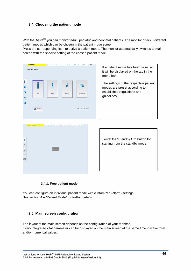
Instructions for Use TeslaM3
MRI Patient Monitoring System All rights reserved – MIPM GmbH 2016 (English-Master-Version 3.1)
46
3.4. Choosing the patient mode
With the TeslaM3
you can monitor adult, pediatric and neonatal patients. The monitor offers 3 different
patient modes which can be chosen in the patient mode screen.
Press the corresponding icon to active a patient mode. The monitor automatically switches to main
screen with the specific setting of the chosen patient mode.
3.4.1. Free patient mode
You can configure an individual patient mode with customized (alarm) settings.
See section 4 – “Patient Mode” for further details.
3.5. Main screen configuration
The layout of the main screen depends on the configuration of your monitor.
Every integrated vital parameter can be displayed on the main screen at the same time in wave form
and/or numerical values.
If a patient mode has been selected
it will be displayed on the tab in the
menu bar.
The settings of the respective patient
modes are preset according to
established regulations and
guidelines.
Touch the “Standby Off” button for
starting from the standby mode.

Instructions for Use TeslaM3
MRI Patient Monitoring System All rights reserved – MIPM GmbH 2016 (English-Master-Version 3.1)
47
3.5.1. Available parameters
Item (Name) REF
number
Parameter (Description)
MRI patient monitor TeslaM3 1800001 Basic configuration
ECG
Pulse oximetry
Non-invasive blood pressure
Option Tesla M3 Remote
Monitor
5450012 Wireless remote monitor, optional
(Wireless connection to a remote screen in the MRI control room*)
Option IBP 1 5200057 Invasive blood pressure, optional
Option IBP 2 5200058 Invasive blood pressure, optional
Option Capno module (CO2)
Tesla M3
5400037 Capnography, optional (i/et CO2, RR)
Option Gas module Tesla M3 5400038 Anesthetic Agents (Auto Detection) , optional (i/et CO2, O2, N2O, ISO, DES, HAL, ENF, SEV)
Option Temperature 1 5800001 Body temperature, optional
Option Temperature 2 5800002 Body temperature, optional
Option Gating TeslaM3 5450014 Gating / Trigger interface, optional
Option Anesthesia View 5000002 Optical interface for Anesthesia View * Mandatory for Hospital network connection
All integrated parameters will be displayed on the main screen and stored in the trend memory.
The main screen is divided into parameter boxes. If a parameter is not integrated in the monitor the
corresponding parameter box is empty.
Every component may be upgraded at any time. This is a hardware upgrade and has to be performed
by MIPM or a service partner authorized and trained by MIPM.
3.5.2. System configuration – The Options Menu
In the options menu you can change all settings
that affect the display layout and routine use of the
monitor.
To open the Options menu press the Options tab
in the menu bar.

Instructions for Use TeslaM3
MRI Patient Monitoring System All rights reserved – MIPM GmbH 2016 (English-Master-Version 3.1)
48
3.5.3. Language
The TeslaM3
is programmed with a selection of languages. Upon delivery the monitor is set to English
language. If you want to change the selected language follow the steps below.
To leave the language menu press the Back icon
Open the Options menu by pressing the
Options tab on the menu bar.
Select Service icon (password protected!).
Select the Language icon or
next page icon to see more languages.
Select the desired language by pressing the
respective icon
The system language is changed and applied
immediately.

Instructions for Use TeslaM3
MRI Patient Monitoring System All rights reserved – MIPM GmbH 2016 (English-Master-Version 3.1)
49
3.5.4. Date and Time
In the Date and Time menu you can change the time format (12/24), time and date. Upon delivery the
TeslaM3
will be set to CET. In order to change that, follow the steps below
To leave the Date / time menu press the back icon
Open the date and time menu by
pressing the Options tab on the
menu bar.
Press the Date / Time icon.
You can change hour : minutes ,
day, month and year individually.
Press the respective icon.
Pressing the +/- icon once changes
the value by 1. Keeping the icon
pressed changes the values faster.
The time format (12/24) can be
changed by pressing the desired
Format in the respective column.
Save the changes by pressing the
Save Icon

Instructions for Use TeslaM3
MRI Patient Monitoring System All rights reserved – MIPM GmbH 2016 (English-Master-Version 3.1)
50
3.5.5. Alarm function
It is possible to deactivate the alarm function of the monitor. However some alarms may still be
displayed in the status bar or main screen.
MIPM strongly recommends to leave the alarm function enabled! Alarms indicate
critical conditions of the patient and the system. Thus alarms help to increase the
awareness of the medical personnel and by that increase patients safety.
Do not suppress an alarm or disable the alarm function if the safety of the patient is
compromised!
To leave the Alarm menu press the back icon
After a new start of the monitor the alarm function will be activated again.
Open the Options menu by pressing the
Options tab on the menu bar.
Select the Alarm icon.
Press On, or Off.
The Alarm function is password protected.
If the alarm function is deactivated you will
see the Alarm Off sign in front of every
single parameter.
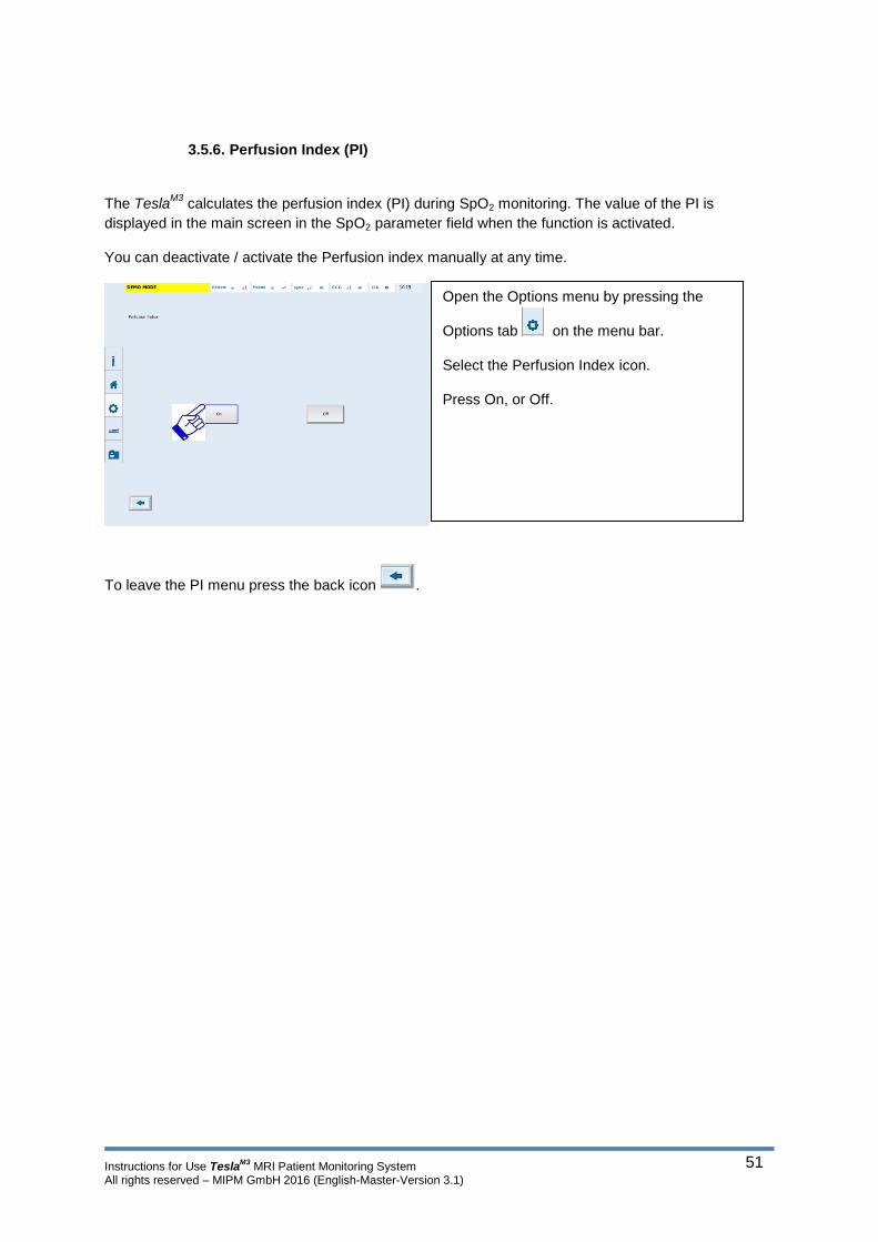
Instructions for Use TeslaM3
MRI Patient Monitoring System All rights reserved – MIPM GmbH 2016 (English-Master-Version 3.1)
51
3.5.6. Perfusion Index (PI)
The TeslaM3
calculates the perfusion index (PI) during SpO2 monitoring. The value of the PI is
displayed in the main screen in the SpO2 parameter field when the function is activated.
You can deactivate / activate the Perfusion index manually at any time.
To leave the PI menu press the back icon .
Open the Options menu by pressing the
Options tab on the menu bar.
Select the Perfusion Index icon.
Press On, or Off.
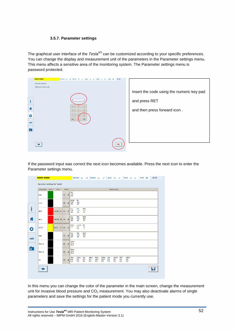
Instructions for Use TeslaM3
MRI Patient Monitoring System All rights reserved – MIPM GmbH 2016 (English-Master-Version 3.1)
52
3.5.7. Parameter settings
The graphical user interface of the TeslaM3
can be customized according to your specific preferences.
You can change the display and measurement unit of the parameters in the Parameter settings menu.
This menu affects a sensitive area of the monitoring system. The Parameter settings menu is
password protected.
If the password input was correct the next icon becomes available. Press the next icon to enter the
Parameter settings menu.
In this menu you can change the color of the parameter in the main screen, change the measurement
unit for invasive blood pressure and CO2 measurement. You may also deactivate alarms of single
parameters and save the settings for the patient mode you currently use.
Insert the code using the numeric key pad
and press RET
and then press forward icon .
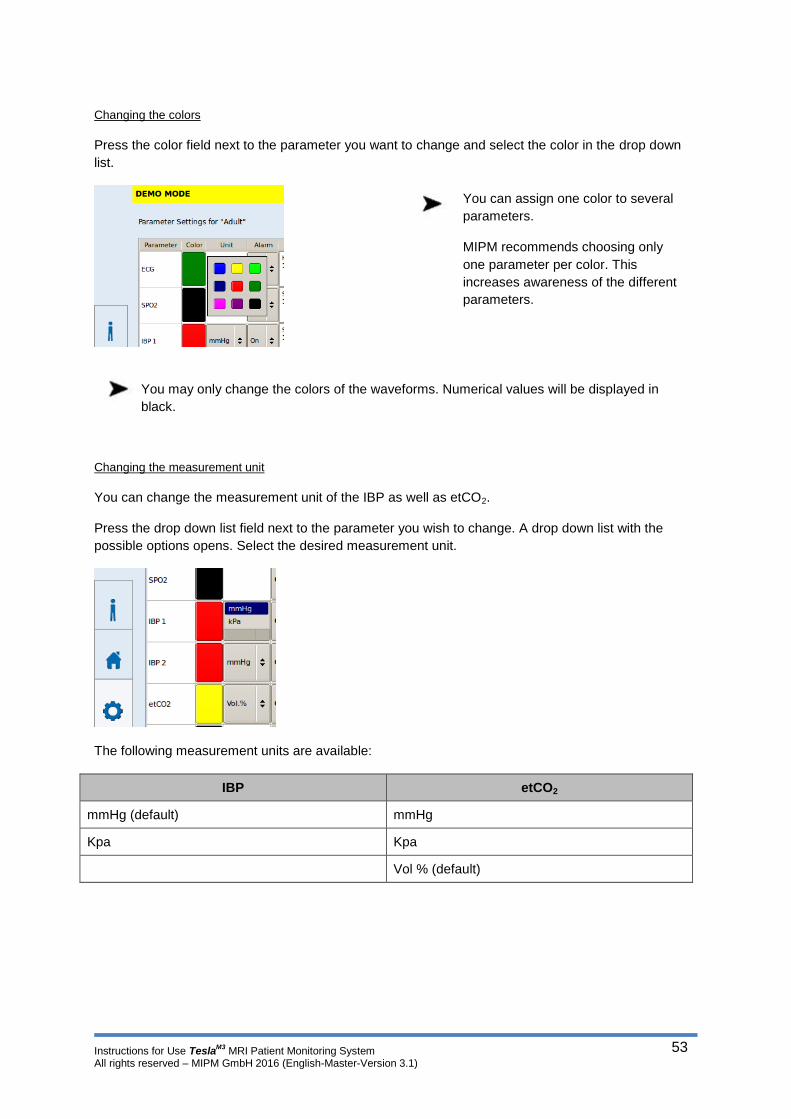
Instructions for Use TeslaM3
MRI Patient Monitoring System All rights reserved – MIPM GmbH 2016 (English-Master-Version 3.1)
53
Changing the colors
Press the color field next to the parameter you want to change and select the color in the drop down
list.
You may only change the colors of the waveforms. Numerical values will be displayed in
black.
Changing the measurement unit
You can change the measurement unit of the IBP as well as etCO2.
Press the drop down list field next to the parameter you wish to change. A drop down list with the
possible options opens. Select the desired measurement unit.
The following measurement units are available:
IBP etCO2
mmHg (default) mmHg
Kpa Kpa
Vol % (default)
You can assign one color to several
parameters.
MIPM recommends choosing only
one parameter per color. This
increases awareness of the different
parameters.

Instructions for Use TeslaM3
MRI Patient Monitoring System All rights reserved – MIPM GmbH 2016 (English-Master-Version 3.1)
54
Changing the alarm status
To enable/ disable the alarm status of a single parameter permanently, press the drop down list field
in the right column for the respective parameter. Choose On, or Off in order to activate / deactivate a
single parameter alarm.
This step may be repeated for every single parameter.
If an alarm status is changed to “Off” in the parameter settings menu and the changes are
saved for the respective patient mode that alarm status will be disabled permanently! Even
after a new start of the monitor the status will be “Off”.
MIPM strongly recommends to leave the alarm function enabled! Alarms indicate
critical conditions of the patient and the system. Thus alarms help to increase the
awareness of the medical personnel and by that increase patients safety.
Do not suppress an alarm or disable the alarm function if the safety of the patient is
compromised!

Instructions for Use TeslaM3
MRI Patient Monitoring System All rights reserved – MIPM GmbH 2016 (English-Master-Version 3.1)
55
Setting the alarm limits
You can set customized alarm limits for each available patient mode. The Alarm limits column in the
Parameter settings menu shows the alarm limits that are currently set. If you want to customize the
alarm limits press the box where the alarm limits are shown in the display.
The alarm limits menu opens. Change the respective alarm limit according to your preferences and
close the alarm limit menu by pressing the back icon. (See section 5 – Changing the alarm limits)
Repeat that procedure for every alarm limit that you want to change.
Saving the parameter settings
If you have finished all parameter settings you have to save the new Setup to activate it for the
respective patient mode.
Press the Save icon and accept.
The changes in the parameter settings are only valid for the patient mode you had selected. If you
want to customize settings of another patient mode go to the Patient Mode screen and select another
patient mode and repeat the steps described above.
The changed setting will only be applied if they are saved before the parameter settings menu
is left. If you leave parameter settings without saving the changes will be discarded.
3.5.8. Service Menu
The Service menu is exclusively reserved for personnel authorized by MIPM. Settings in the
Service menu affect sensitive areas of the systems core functions and may only be changed by
trained personnel.
The Service menu is password protected.
For any information about the service menu contact MIPM or your local service partner.

Instructions for Use TeslaM3
MRI Patient Monitoring System All rights reserved – MIPM GmbH 2016 (English-Master-Version 3.1)
56
3.6. Monitor volume and Standby mode
The Volume for the alarm and pulse tone can be adjusted in 4 levels.
Open the Volume menu by pressing the volume icon ( ) on the main screen
During standby mode the alarm function and the trend memory are deactivated.
3.7. Connecting Patient Sensors to the TeslaM3
All connectors for sensors are to be found on the back side of the unit.
For more detailed picture see section 1 – Back of the device
ECG, as well as SpO2 sensor have a wireless connection to
the monitor.
Chose the desired volume level for
pulse,
or alarm tone by pressing the
respective bar in the volume window.
Press Standby to set the monitor in
standby mode.
Press the Standby off icon on the
main screen to leave standby mode.
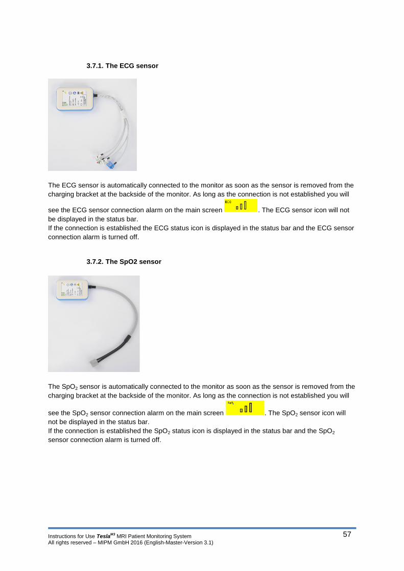
Instructions for Use TeslaM3
MRI Patient Monitoring System All rights reserved – MIPM GmbH 2016 (English-Master-Version 3.1)
57
3.7.1. The ECG sensor
The ECG sensor is automatically connected to the monitor as soon as the sensor is removed from the
charging bracket at the backside of the monitor. As long as the connection is not established you will
see the ECG sensor connection alarm on the main screen . The ECG sensor icon will not
be displayed in the status bar.
If the connection is established the ECG status icon is displayed in the status bar and the ECG sensor
connection alarm is turned off.
3.7.2. The SpO2 sensor
The SpO2 sensor is automatically connected to the monitor as soon as the sensor is removed from the
charging bracket at the backside of the monitor. As long as the connection is not established you will
see the SpO2 sensor connection alarm on the main screen . The SpO2 sensor icon will
not be displayed in the status bar.
If the connection is established the SpO2 status icon is displayed in the status bar and the SpO2
sensor connection alarm is turned off.
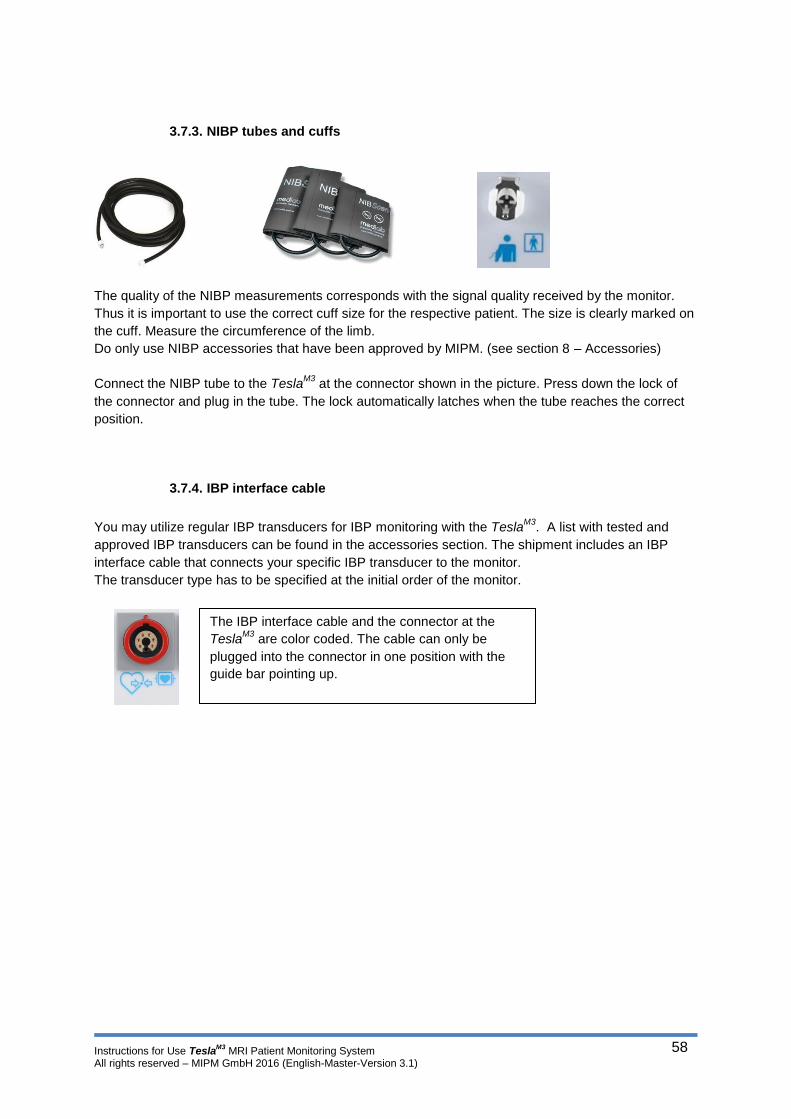
Instructions for Use TeslaM3
MRI Patient Monitoring System All rights reserved – MIPM GmbH 2016 (English-Master-Version 3.1)
58
3.7.3. NIBP tubes and cuffs
The quality of the NIBP measurements corresponds with the signal quality received by the monitor.
Thus it is important to use the correct cuff size for the respective patient. The size is clearly marked on
the cuff. Measure the circumference of the limb.
Do only use NIBP accessories that have been approved by MIPM. (see section 8 – Accessories)
Connect the NIBP tube to the TeslaM3
at the connector shown in the picture. Press down the lock of
the connector and plug in the tube. The lock automatically latches when the tube reaches the correct
position.
3.7.4. IBP interface cable
You may utilize regular IBP transducers for IBP monitoring with the Tesla
M3. A list with tested and
approved IBP transducers can be found in the accessories section. The shipment includes an IBP
interface cable that connects your specific IBP transducer to the monitor.
The transducer type has to be specified at the initial order of the monitor.
The IBP interface cable and the connector at the
TeslaM3
are color coded. The cable can only be
plugged into the connector in one position with the
guide bar pointing up.

Instructions for Use TeslaM3
MRI Patient Monitoring System All rights reserved – MIPM GmbH 2016 (English-Master-Version 3.1)
59
3.7.5. Gas sample lines and water traps
3.7.6. The temperature sensor
Gas sample line for
capnography and
Multigas module
Nasal gas sample
line for capnography
module
Airway connector for
patient connection
(Capnography
module)
Water trap for
capnography
module
Water trap for
Multigas module
Temperature sensor for
intracorporeal temperature
measurement
Temperature sensor for surface
temperature measurement
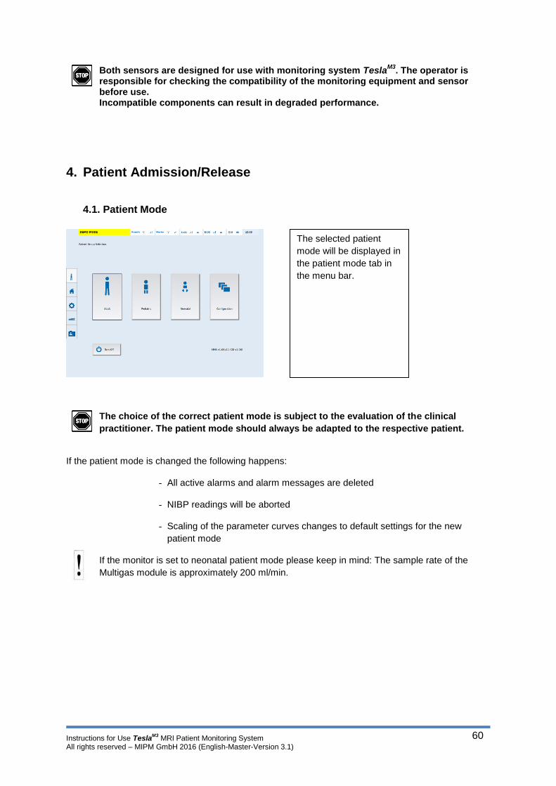
Instructions for Use TeslaM3
MRI Patient Monitoring System All rights reserved – MIPM GmbH 2016 (English-Master-Version 3.1)
60
Both sensors are designed for use with monitoring system TeslaM3
. The operator is responsible for checking the compatibility of the monitoring equipment and sensor before use. Incompatible components can result in degraded performance.
4. Patient Admission/Release
4.1. Patient Mode
The choice of the correct patient mode is subject to the evaluation of the clinical
practitioner. The patient mode should always be adapted to the respective patient.
If the patient mode is changed the following happens:
- All active alarms and alarm messages are deleted
- NIBP readings will be aborted
- Scaling of the parameter curves changes to default settings for the new
patient mode
If the monitor is set to neonatal patient mode please keep in mind: The sample rate of the
Multigas module is approximately 200 ml/min.
The selected patient
mode will be displayed in
the patient mode tab in
the menu bar.
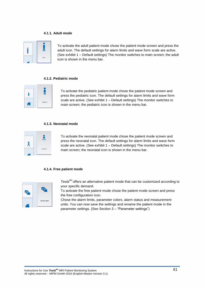
Instructions for Use TeslaM3
MRI Patient Monitoring System All rights reserved – MIPM GmbH 2016 (English-Master-Version 3.1)
61
4.1.1. Adult mode
To activate the adult patient mode chose the patient mode screen and press the
adult icon. The default settings for alarm limits and wave form scale are active.
(See exhibit 1 – Default settings) The monitor switches to main screen; the adult
icon is shown in the menu bar.
4.1.2. Pediatric mode
To activate the pediatric patient mode chose the patient mode screen and
press the pediatric icon. The default settings for alarm limits and wave form
scale are active. (See exhibit 1 – Default settings) The monitor switches to
main screen; the pediatric icon is shown in the menu bar.
4.1.3. Neonatal mode
To activate the neonatal patient mode chose the patient mode screen and
press the neonatal icon. The default settings for alarm limits and wave form
scale are active. (See exhibit 1 – Default settings) The monitor switches to
main screen; the neonatal icon is shown in the menu bar.
4.1.4. Free patient mode
TeslaM3
offers an alternative patient mode that can be customized according to
your specific demand.
To activate the free patient mode chose the patient mode screen and press
the free configuration icon.
Chose the alarm limits, parameter colors, alarm status and measurement
units. You can now save the settings and rename the patient mode in the
parameter settings. (See Section 3 – “Parameter settings”)

Instructions for Use TeslaM3
MRI Patient Monitoring System All rights reserved – MIPM GmbH 2016 (English-Master-Version 3.1)
62
4.2. Patient admission
Whenever the Tesla
M3 is switched on the monitor asks if there is a new patient. This ensures that the
data from previous patients is deleted before a new patient is monitored.
If you want to monitor a new patient chose Yes; all previous patient information, and trends are
deleted.
You can always change patient data at any time during the examination.
In the parameter settings menu you can
assign a basic patient mode to the free
configuration. Press the drop down list in
the upper right corner of the display and
chose the patient type
Before saving the settings you can rename
the configuration by pressing the icon on
the bottom of the main screen. Type in the
new name for the patient mode using the
keyboard interface and save the changes.
To finish the parameter settings press the
Save Icon in the lower right corner of the
display.

Instructions for Use TeslaM3
MRI Patient Monitoring System All rights reserved – MIPM GmbH 2016 (English-Master-Version 3.1)
63
4.2.1. Enter patient data
All patient information can be entered in the patient data screen. Press the Patient data tab in the
menu bar; the patient data screen will be displayed.
If the memory already contains patient data the name of the patient will be displayed on the screen.
To enter new patient data press the Enter new patient icon.
Type the patient data using the display keyboard. Select the respective box by pressing on it. You can
either put it data independently via the keyboard or by drop down list. Any input has to be confirmed
with “Return” before the next box can be selected.
The following data may be stored:
Medical record number First name Family name Patient group
Date of birth Gender Height Weight
Save the patient date by pressing the disc icon . The patient information will be used for all trend records until the patient is released, or a new patient is admitted.

Instructions for Use TeslaM3
MRI Patient Monitoring System All rights reserved – MIPM GmbH 2016 (English-Master-Version 3.1)
64
4.2.2. Utilization of patient data
If a patient is registered at the monitor all vital signs measurements are assigned to that patient. The
trend data (tabular, event) can be copied to an external data storage medium (USB) or printed. Trend
data is transmitted in the .csv file format. Each data string carries the complete patient information that
has been stored in the monitor.
The trend data in .csv format can be changed to any other file format.
If the TeslaM3
is connected to a hospital network all patient and trend data will be transferred to
the local area network.
4.3. Patient release
After a patient release all patient data including trend memory will be erased. The monitor resets
all values to the default settings of the chosen patient mode.
To release a patient chose the patient data screen and press the Release patient icon.
Confirm patient release.

Instructions for Use TeslaM3
MRI Patient Monitoring System All rights reserved – MIPM GmbH 2016 (English-Master-Version 3.1)
65
4.4. Connecting TeslaM3 to a hospital network (PDMS)
The customization of the data protocol in order to align the TeslaM3
data with the hospital network
cannot be performed by MIPM. The actual implementation of the monitor to the hospital network has
to be done by the network administrator or the provider of the hospital network.
TeslaM3
provides the monitoring data (.xml File).
The transmission of monitoring data via Ethernet happens by creation of a XML file with equivalent
content as data transmitted via RS232. The transmission of data to the PDMS server is based on
Secure Copy – scp with Secure Shell – SSH authentication.
In order to connect TeslaM3
to the hospital network, the monitor as well as the PDMS server have to be
configured. The patterns of the configuration are not part of this user manual.
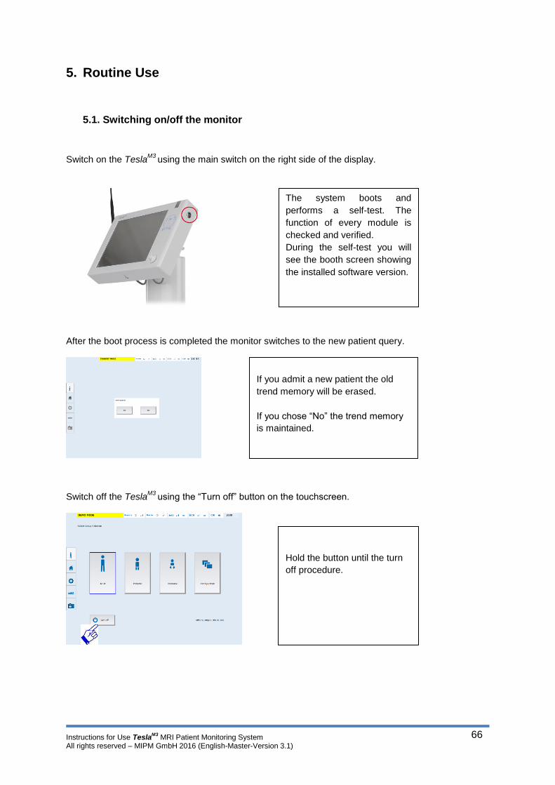
Instructions for Use TeslaM3
MRI Patient Monitoring System All rights reserved – MIPM GmbH 2016 (English-Master-Version 3.1)
66
5. Routine Use
5.1. Switching on/off the monitor
Switch on the TeslaM3
using the main switch on the right side of the display.
After the boot process is completed the monitor switches to the new patient query.
Switch off the TeslaM3
using the “Turn off” button on the touchscreen.
The system boots and
performs a self-test. The
function of every module is
checked and verified.
During the self-test you will
see the booth screen showing
the installed software version.
If you admit a new patient the old
trend memory will be erased.
If you chose “No” the trend memory
is maintained.
Hold the button until the turn
off procedure.
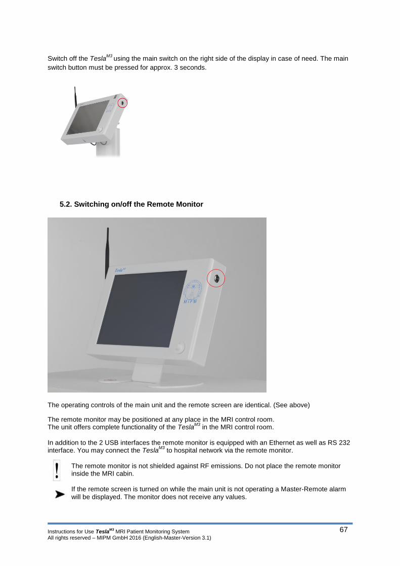
Instructions for Use TeslaM3
MRI Patient Monitoring System All rights reserved – MIPM GmbH 2016 (English-Master-Version 3.1)
67
Switch off the Tesla
M3 using the main switch on the right side of the display in case of need. The main
switch button must be pressed for approx. 3 seconds.
5.2. Switching on/off the Remote Monitor
The operating controls of the main unit and the remote screen are identical. (See above)
The remote monitor may be positioned at any place in the MRI control room. The unit offers complete functionality of the Tesla
M3 in the MRI control room.
In addition to the 2 USB interfaces the remote monitor is equipped with an Ethernet as well as RS 232 interface. You may connect the Tesla
M3 to hospital network via the remote monitor.
The remote monitor is not shielded against RF emissions. Do not place the remote monitor inside the MRI cabin.
If the remote screen is turned on while the main unit is not operating a Master-Remote alarm will be displayed. The monitor does not receive any values.

Instructions for Use TeslaM3
MRI Patient Monitoring System All rights reserved – MIPM GmbH 2016 (English-Master-Version 3.1)
68
5.3. Handling the wireless sensors
The TeslaM3
is equipped with two wireless sensors. Both sensors have an integrated battery and
battery charger. You may charge the sensor batteries in the charging brackets on the back side of the
monitor. Please insert the sensors to the charging brackets as described below.
Insert the sensor with the cable pointing downwards into the charging bracket. Make sure that the
cable meets the outlet off the charging bracket.
When the sensor is placed in the charging bracket it will be deactivated and automatically charged.
The sensor connection alarm icon will be displayed in the main screen and the sensor status field in
the status bar will be marked yellow. The charging process is indicated by the 3 sensors overhead
LEDs flashing one after the other. of the 3 LEDs on the sensor.
For a complete recharge of the sensor battery charge the sensor for at least 6 hours.
Make sure that the sensor batteries are always fully charged before using the TeslaM3
.

Instructions for Use TeslaM3
MRI Patient Monitoring System All rights reserved – MIPM GmbH 2016 (English-Master-Version 3.1)
69
5.3.1. The ECG sensor
The ECG cables are made of carbon fibers. This reduces the risk of cable heating to a minimum.
Placement of the ECG electrodes will be described in the chapter ECG electrodes and skin
preparation.
The battery of the ECG sensor lasts for at least 8 hours if it was charged completely. You may check
the battery status of the sensor on the 3 LEDs directly at the sensor or in the sensor status field in the
status bar.
If the battery status is low a status message will be generated in the status bar. Charge the
sensor immediately. Insert the sensor in the charging bracket as described above.
To activate the ECG sensor remove it from the charging bracket. The sensor is activated
automatically, performs a self-test and establishes the connection with the TeslaM3®
.
The ECG sensor connection alarm disappears and the ECG sensor status field in the status bar is
displayed.
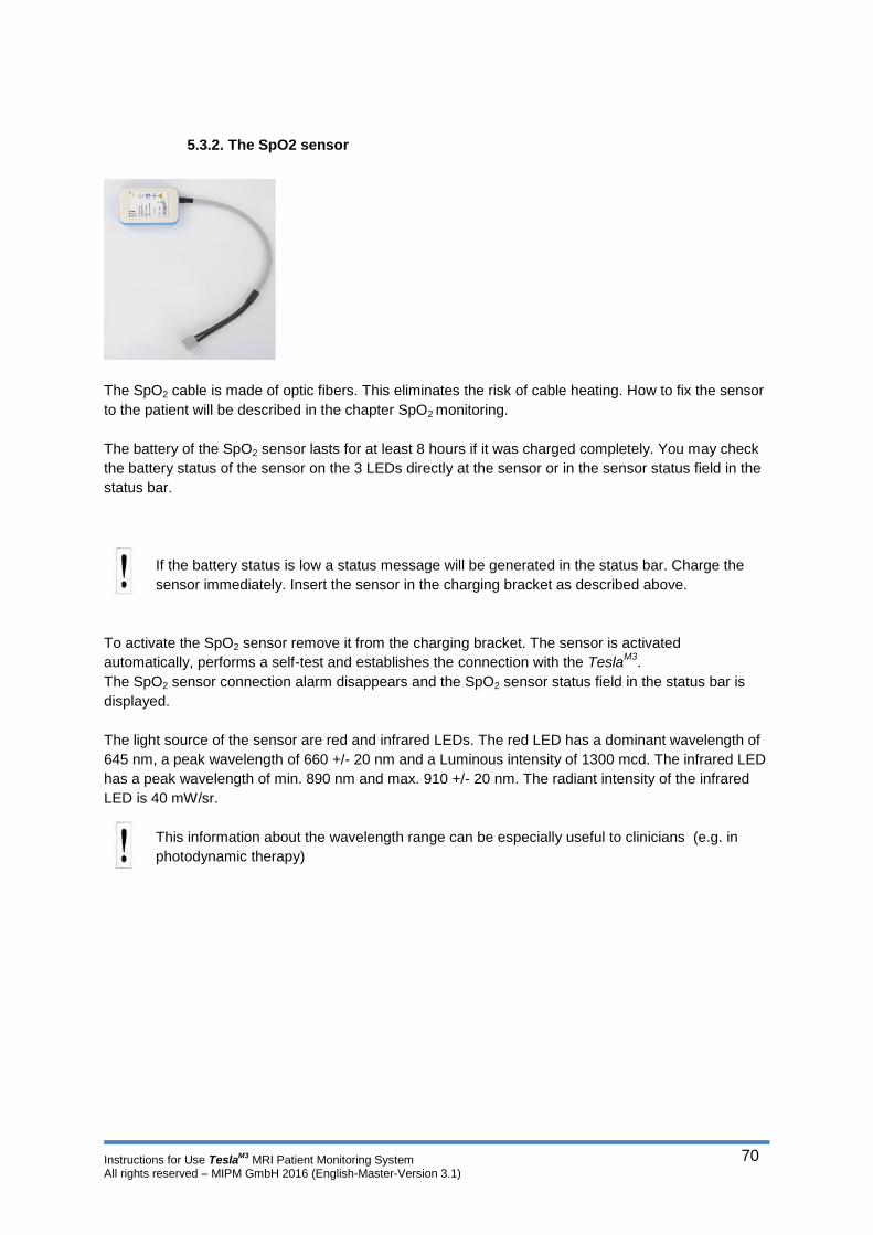
Instructions for Use TeslaM3
MRI Patient Monitoring System All rights reserved – MIPM GmbH 2016 (English-Master-Version 3.1)
70
5.3.2. The SpO2 sensor
The SpO2 cable is made of optic fibers. This eliminates the risk of cable heating. How to fix the sensor
to the patient will be described in the chapter SpO2 monitoring.
The battery of the SpO2 sensor lasts for at least 8 hours if it was charged completely. You may check
the battery status of the sensor on the 3 LEDs directly at the sensor or in the sensor status field in the
status bar.
If the battery status is low a status message will be generated in the status bar. Charge the
sensor immediately. Insert the sensor in the charging bracket as described above.
To activate the SpO2 sensor remove it from the charging bracket. The sensor is activated
automatically, performs a self-test and establishes the connection with the TeslaM3
.
The SpO2 sensor connection alarm disappears and the SpO2 sensor status field in the status bar is
displayed.
The light source of the sensor are red and infrared LEDs. The red LED has a dominant wavelength of
645 nm, a peak wavelength of 660 +/- 20 nm and a Luminous intensity of 1300 mcd. The infrared LED
has a peak wavelength of min. 890 nm and max. 910 +/- 20 nm. The radiant intensity of the infrared
LED is 40 mW/sr.
This information about the wavelength range can be especially useful to clinicians (e.g. in
photodynamic therapy)

Instructions for Use TeslaM3
MRI Patient Monitoring System All rights reserved – MIPM GmbH 2016 (English-Master-Version 3.1)
71
5.4. The main screen
The parameter boxes are fixed on the main screen. If the TeslaM3
is not equipped with a
parameter the respective parameter box remains empty.
E.g. Configuration: ECG, SpO2, NIBP, 1x IBP, 1x Temperature, Multigas module
From the main screen you can change any relevant setting. All parameter menus (e.g. Alarm limits, scaling, ECG leads) may be selected in the main screen. Via the function icons at the bottom of the main screen you can manually start and stop a NIBP measurement, suppress an alarm, set the monitor volume and put the monitor into Standby mode. You will find information about the status of the monitor and its components, as well as alarm messages in the status bar above the main screen.
Parameter box - ECG
Parameter box - SpO2
Parameter box - IBP 1
Parameter box - IBP 2
Parameter box -
Capnography
NIBP Start / Stop Icon Quit alarm icon Change digit size Standby icon Volume
Standby menu
Temperature1
Parameter box NIBP Parameter
box
Temperature 2 Parameter box
Multigas module Parameter box
The parameter box for IBP1 remains
empty and cannot be programmed by
the user.
ECG cascade may be activated or
deactivated at any time during the
examination.

Instructions for Use TeslaM3
MRI Patient Monitoring System All rights reserved – MIPM GmbH 2016 (English-Master-Version 3.1)
72
Using the function bar on the left side of the screen you can change to any other screen at any time.
Colors or units of the parameters can be changed as described in Chapter 3 – Parameter settings.
All vital signs will be shown directly in the main screen as soon as the respective sensor is connected
to the patient.
Each parameter box can be activated via
the touch screen. By pressing on one of
the parameter boxes the corresponding
parameter menu will be opened.
Please see the corresponding chapter
for more details about the settings in the
parameter menus.

Instructions for Use TeslaM3
MRI Patient Monitoring System All rights reserved – MIPM GmbH 2016 (English-Master-Version 3.1)
73
5.5. Alarms
TeslaM3
is equipped with different alarm mechanisms (System/Technical alarms, Parameter alarms).
All alarms will be displayed in the main screen either in the status bar or directly in the parameter
boxes. Every alarm has an assigned priority (see Alarm priorities). In case of multiple alarms,
messages rotate in an interval of 5 seconds. A table with alarms is created in the background like the
following.
Alarms are sorted by 1. priority and 2. time of occurrence
Sorted by priority and time of occurrence
Alarms Comment
1 ASY High - first occurred
2 IBP Malfunction High - last occurred
3 Occlusion Medium
4 Temp. Sensor Disconnected
Low
If a parameter alarm is reported, all other parameters are represented in a milky tone. The Loudness of audible alarms of high priority is up to 66 and medium/low priority up to 60 dB. The alarm signal sound pressure level should be adjusted depending on ambient noise.
5.5.1. Battery alarms
The monitor as well as ECG and SpO2 sensor may be used in battery operation. The battery life for the monitor is approximately 6.5 hours – 390 minutes (tested with standard
configuration). Battery life of the sensors is at least 8 hours – 480 minutes.
If a battery alarm occurs, please connect the TeslaM3
to mains power immediately. When the
first battery alarm (≤10%) is shown the remaining battery life is approximately 30 minutes. If
the TeslaM3
is not connected to the mains power after the second battery alarm the system will
shut down after a few minutes.
The charge condition of the battery will be displayed as shown left.
If the charging condition reaches ≤10% of the capacity an alarm is
generated.
- The battery symbol of the affected component appears yellow
- You will see a yellow message in the status bar
- A single alarm tone sounds
If the charge condition reaches ≤ 5% of the capacity the general battery
alarm is replaced by a critical battery alarm.
- The battery symbol of the affected component flashes red
- You will see a red message in the status bar
- A repeated alarm tone sounds.
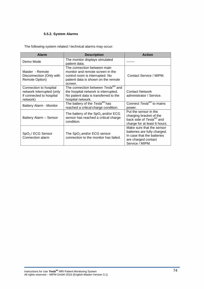
Instructions for Use TeslaM3
MRI Patient Monitoring System All rights reserved – MIPM GmbH 2016 (English-Master-Version 3.1)
74
5.5.2. System Alarms
The following system related / technical alarms may occur:
Alarm Description Action
Demo Mode The monitor displays simulated patient data.
-------
Master - Remote Disconnection (Only with Remote Option)
The connection between main monitor and remote screen in the control room is interrupted. No patient data is shown on the remote screen.
Contact Service / MIPM.
Connection to hospital network interrupted (only if connected to hospital network)
The connection between TeslaM3
and the hospital network is interrupted. No patient data is transferred to the hospital network.
Contact Network administrator / Service.
Battery Alarm - Monitor The battery of the Tesla
M3 has
reached a critical charge condition.
Connect TeslaM3
to mains power.
Battery Alarm – Sensor The battery of the SpO2 and/or ECG sensor has reached a critical charge condition.
Put the sensor in the charging bracket of the back side of Tesla
M3 and
charge for at least 6 hours.
SpO2 / ECG Sensor Connection alarm
The SpO2 and/or ECG sensor connection to the monitor has failed.
Make sure that the sensor batteries are fully charged. In case that the batteries are charged contact Service / MIPM.

Instructions for Use TeslaM3
MRI Patient Monitoring System All rights reserved – MIPM GmbH 2016 (English-Master-Version 3.1)
75
5.5.3. Parameter Alarms
The following parameter related alarm may occur:
Alarm Description
Violation of an alarm limit
One or more of the vital signs have violated the upper or lower alarm limit of a parameter. The respective parameter box flashes red and an acoustic alarm sounds.
ASY The monitor recognized a cardiac arrest. The ECG box flashes red and ASY is displayed in the ECG box.
BRADY (only in adult patient mode) The monitor recognized a Bradycardia (Heart rate < 60). BRADY is displayed in the ECG box. No alarm tone will sound.
TACHY
The monitor recognized a Tachycardia (Heart rate >150) TACHY is displayed in the ECG box. If the Tachycardia corresponds with a violation of an alarm limit the ECG box flashes red.
ECG Lead Off
One or more of the ECG electrodes are not properly connected to the patient or the ECG sensor. It may also happen that the skin resistance is too high (see ECG chapter).
SpO2 – Finger not in sensor The SpO2 sensor is not properly connected to the patient’s finger.
Alarms Overview
module / parameter
alarm cause priority message displayed in
status bar behaviour
message location
CIB CIB Malfunction High System Malfunction Status message Status bar
Master / CIB Connection Lost High No communication with CIB
Status message Status bar (Master monitor)
Master / Remote
Demo Mode Low Demo mode - simulated data
Status message Status bar
Master / Remote
Service Mode Low Master in service mode Status message Status bar
Master / Remote
Connection Lost Low No communication with master
Status message Status bar (Remote monitor)
PDMS / Network
No patient data Low No data transmission - Patient data missing
Status message Status bar
SPO2 Battery Charge Condition 10% Low SPO2 Battery < 10 % Status message Status bar
SPO2 Battery Charge Condition 5% High SPO2 battery < 5 % Status message Status bar
ECG Battery Charge Condition 10% Low ECG battery < 10% Status message Status bar
ECG Battery Charge Condition 5% High ECG battery < 5 % Status message Status bar
System Battery
Charge Condition 10% Low System battery < 10 % Status message Status bar
System Battery
Charge Condition 5% High Low battery - shutdown in a few minutes
Status message Status bar
NIBP Selftest Error High NIBP System Malfunction Status message Status bar
NIBP System Error in measuring unit
High NIBP System Malfunction Status message Status bar
NIBP Leakage during leakage test
Low NIBP Leakage Status message Status bar
NIBP Cuff fitted to losely or not connected
Low Check NIBP Cuff placement
Status message Status bar
NIBP Leakage during operation
Medium NIBP Leakage Status message Status bar
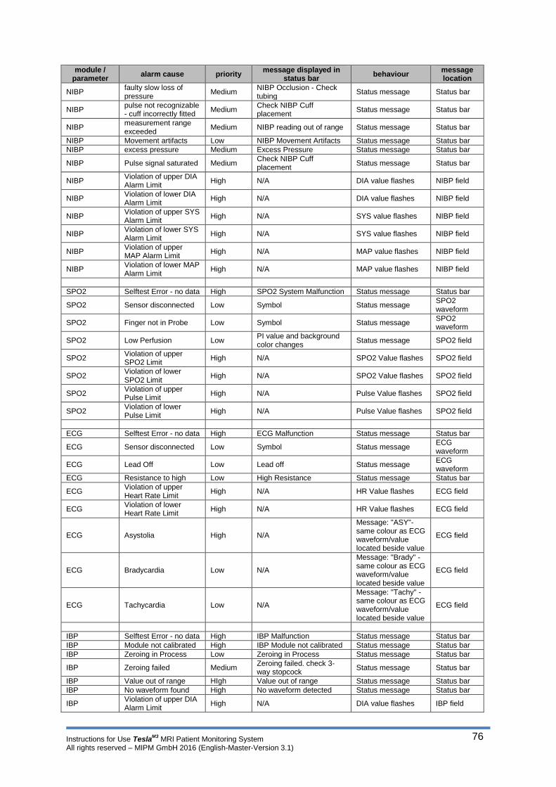
Instructions for Use TeslaM3
MRI Patient Monitoring System All rights reserved – MIPM GmbH 2016 (English-Master-Version 3.1)
76
module / parameter
alarm cause priority message displayed in
status bar behaviour
message location
NIBP faulty slow loss of pressure
Medium NIBP Occlusion - Check tubing
Status message Status bar
NIBP pulse not recognizable - cuff incorrectly fitted
Medium Check NIBP Cuff placement
Status message Status bar
NIBP measurement range exceeded
Medium NIBP reading out of range Status message Status bar
NIBP Movement artifacts Low NIBP Movement Artifacts Status message Status bar
NIBP excess pressure Medium Excess Pressure Status message Status bar
NIBP Pulse signal saturated Medium Check NIBP Cuff placement
Status message Status bar
NIBP Violation of upper DIA Alarm Limit
High N/A DIA value flashes NIBP field
NIBP Violation of lower DIA Alarm Limit
High N/A DIA value flashes NIBP field
NIBP Violation of upper SYS Alarm Limit
High N/A SYS value flashes NIBP field
NIBP Violation of lower SYS Alarm Limit
High N/A SYS value flashes NIBP field
NIBP Violation of upper MAP Alarm Limit
High N/A MAP value flashes NIBP field
NIBP Violation of lower MAP Alarm Limit
High N/A MAP value flashes NIBP field
SPO2 Selftest Error - no data High SPO2 System Malfunction Status message Status bar
SPO2 Sensor disconnected Low Symbol Status message SPO2 waveform
SPO2 Finger not in Probe Low Symbol Status message SPO2 waveform
SPO2 Low Perfusion Low PI value and background color changes
Status message SPO2 field
SPO2 Violation of upper SPO2 Limit
High N/A SPO2 Value flashes SPO2 field
SPO2 Violation of lower SPO2 Limit
High N/A SPO2 Value flashes SPO2 field
SPO2 Violation of upper Pulse Limit
High N/A Pulse Value flashes SPO2 field
SPO2 Violation of lower Pulse Limit
High N/A Pulse Value flashes SPO2 field
ECG Selftest Error - no data High ECG Malfunction Status message Status bar
ECG Sensor disconnected Low Symbol Status message ECG waveform
ECG Lead Off Low Lead off Status message ECG waveform
ECG Resistance to high Low High Resistance Status message Status bar
ECG Violation of upper Heart Rate Limit
High N/A HR Value flashes ECG field
ECG Violation of lower Heart Rate Limit
High N/A HR Value flashes ECG field
ECG Asystolia High N/A
Message: "ASY"- same colour as ECG waveform/value located beside value
ECG field
ECG Bradycardia Low N/A
Message: "Brady" - same colour as ECG waveform/value located beside value
ECG field
ECG Tachycardia Low N/A
Message: "Tachy" - same colour as ECG waveform/value located beside value
ECG field
IBP Selftest Error - no data High IBP Malfunction Status message Status bar
IBP Module not calibrated High IBP Module not calibrated Status message Status bar
IBP Zeroing in Process Low Zeroing in Process Status message Status bar
IBP Zeroing failed Medium Zeroing failed. check 3-way stopcock
Status message Status bar
IBP Value out of range HIgh Value out of range Status message Status bar
IBP No waveform found High No waveform detected Status message Status bar
IBP Violation of upper DIA Alarm Limit
High N/A DIA value flashes IBP field

Instructions for Use TeslaM3
MRI Patient Monitoring System All rights reserved – MIPM GmbH 2016 (English-Master-Version 3.1)
77
module / parameter
alarm cause priority message displayed in
status bar behaviour
message location
IBP Violation of lower DIA Alarm Limit
High N/A DIA value flashes IBP field
IBP Violation of upper SYS Alarm Limit
High N/A SYS value flashes IBP field
IBP Violation of lower SYS Alarm Limit
High N/A SYS value flashes IBP field
IBP Violation of upper MAP Alarm Limit
High N/A MAP value flashes IBP field
IBP Violation of lower MAP Alarm Limit
High N/A MAP value flashes IBP field
IBP Cable failure Medium Cable fail Status message Status bar
CO2 Selftest Error - no data High Capnography Malfunction Status message Status bar
CO2 Sample Line is occluded
Medium Occlusion Status message Status bar
CO2 No flow detected Medium No Flow Status message Status bar
CO2 Flow is too low Medium Low Flow Status message Status bar
CO2 Flow is too high Medium High Flow Status message Status bar
CO2 No Filter is connected to the module
Low Check Filter Status message Status bar
CO2 Run Time - Unit should be calibrated
Low Run Time - Calibrate CO2 Module
Status message Status bar
CO2 Violation of upper iCO2 Limit
High N/A iCO2 values flashes CO2 field
CO2 Violation of lower iCO2 Limit
High N/A iCO2 values flashes CO2 field
CO2 Violation of upper etCO2 Limit
High N/A etCO2 value flashes CO2 field
CO2 Violation of lower etCO2 Limit
High N/A etCO2 value flashes CO2 field
CO2 Violation of upper Respiration Rate Limit
High N/A RR value flashes CO2 field
CO2 Violation of lower Respiration Rate Limit
High N/A RR value flashes CO2 field
CO2 5% calibration startet Low 5% calibration startet Status message Status bar
CO2 5% calibration ended Low 5% calibration ended Status message Status bar
Gasmodule Selftest Error - no data High Gas Module Malfunction Status message Status bar
Gasmodule No flow detected Medium No Flow Status message Status bar
Gasmodule Flow is too low Medium Low Flow Status message Status bar
Gasmodule Flow is too high Medium High Flow Status message Status bar
Gasmodule Violation of upper iAA Limit
High N/A iAA Value flashes AA Field
Gasmodule Violation of lower iAA Limit
High N/A iAA Value flashes AA Field
Gasmodule Violation of upper etAA Limit
High N/A etAA value flashes AA Field
Gasmodule Violation of lower etAA Limit
High N/A etAA value flashes AA Field
Gasmodule Violation of upper etO2 Limit
High N/A etO2 value flashes AA Field
Gasmodule Violation of lower etO2 Limit
High N/A etO2 value flashes AA Field
Gasmodule Violation of upper Respiration Rate Limit
High N/A RR value flashes AA Field
Gasmodule Violation of lower Repsiration Rate Limit
High N/A RR value flashes AA Field
Gasmodule More than one AA High More than one AA detected
Status message Status bar
Gasmodule Component failure High Gas Module Malfunction Status message Status bar
Gasmodule Multigas warm up Low Multigas warm up Status message Status bar
Gasmodule Multigas zero in 1 minute
Low Multigas zero in 1 minute Status message Status bar
Gasmodule Multigas zero in progress
Low Multigas zero in progress Status message Status bar
Gasmodule Watertrap full / error Low Check Watertrap Status message Status bar
Temperature Selftest Error - no data High Temperature Malfunction Status message Status bar
Temperature Sensor disconnected (channel 1)
Low Temp. Sensor Disconnected (channel 1)
Status message Status bar

Instructions for Use TeslaM3
MRI Patient Monitoring System All rights reserved – MIPM GmbH 2016 (English-Master-Version 3.1)
78
module / parameter
alarm cause priority message displayed in
status bar behaviour
message location
Temperature Sensor disconnected (channel 2)
Low Temp. Sensor Disconnected (channel 2)
Status message Status bar
Temperature Violation of upper Temperature Limit
High N/A Temperature value flashes
Temperature field
Temperature Violation of lower Temperature Limit
High N/A Temperature value flashes
Temperature field
Alarm delays There is a delay for the alarm “No communication with master”. The delay time from the onset of the alarm condition to the point of representation and the maximum remote alarm signal generation delay are 2 seconds.

Instructions for Use TeslaM3
MRI Patient Monitoring System All rights reserved – MIPM GmbH 2016 (English-Master-Version 3.1)
79
5.5.4. Alarm priorities
The priority setting of alarms does not take into account if the alarm is parameter related or
system related. Only the potential danger for the patient or personnel matters for the
evaluation of an alarm priority.
Alarm priorities:
Red: Life threatening alarm – High priority
The monitor recognizes a life threatening alarm condition (e.g. violation of an alarm limit)
A life threatening alarm has the following properties:
- The parameter box flashes red
- A repeated acoustic alarm sounds
- The alarm remains active until manually suppressed by the user or the cause
of the alarm ends.
Yellow: Dangerous Alarm – Medium Priority
The monitor recognizes a dangerous alarm condition (e.g. occlusion in sample lines)
A dangerous alarm shows a significant disturbance of the monitors functionality and has the following
properties:
- The symbol in the parameter box or the status bar flashes yellow
- An acoustic alarm sounds
- The alarm remains active until the cause for the alarm ends.
- The alarm is put in the background if a life threatening alarm occurs
Yellow: Information – Low priority
The monitor informs about certain conditions of the system, a system component or a technical
problem.
An information alarm has the following properties:
- The symbol in the parameter box or the status bar flashes yellow
- A single alarm tone sounds
- The alarm is put in the background if a dangerous or life threatening alarm
occurs
- The alarm remains active until the cause for the alarm ends
5.5.5. Activate and deactivate the alarm function
It is possible to completely deactivate the alarm function for audible alarms.
MIPM strongly recommends to leave the alarm function enabled! Alarms indicate
critical conditions of the patient and the system. Thus alarms help to increase the
awareness of the medical personnel and by that increase patients safety.
Do not suppress an alarm or disable the alarm function if the safety of the patient is
compromised!
For more details see chapter 3 – Alarm function

Instructions for Use TeslaM3
MRI Patient Monitoring System All rights reserved – MIPM GmbH 2016 (English-Master-Version 3.1)
80
5.5.6. Activate and deactivate single parameter alarms
It is possible to deactivate the audible single parameter alarms.
You will find the “Alarm status” sub menu in every parameter menu (see following pages). You can
deactivate the audible alarm function of each parameter in that sub menu. After the audible alarms are
disabled the flashing symbol “Bell cancel” as a reminder signal will appear. The flashing frequency is 1
Hz.
E.g. SpO2 Parameter box
Press the parameter box of the parameter
you want to change in the main screen.
The respective parameter menu opens.
Press the Alarm status bar.
Chose the desired alarm status by
pressing On or Off.
If the alarm function of a
single parameter is
deactivated you will see the
Alarm function disabled icon
left to the respective
parameter box.
E.g. SpO2

Instructions for Use TeslaM3
MRI Patient Monitoring System All rights reserved – MIPM GmbH 2016 (English-Master-Version 3.1)
81
5.5.7. Alarm silence and the adjust alarm function
If an alarm occurs the monitor offer two possibilities.
1. Activate Alarm silence within 120 seconds (Only the acoustic alarm is suppressed, the
parameter box keeps flashing red)
2. Adjust the alarm limit using the adjust alarm function
Alarm silence:
If a parameter or system alarm occurs you can suppress the alarm for 2 minutes by pressing the
Alarm silence icon ( ) at the bottom of the main screen.
After the audible alarms are disabled the flashing symbol “Bell cancel” as a reminder signal will
appear. The flashing frequency is 1 Hz.
During Alarm silence the alarm silence icon and a
countdown will be displayed in the upper left
corner of the main screen.
If the cause for the alarm is not eliminated within
the 120 seconds the alarm tone sets in again.
You can end the alarm silence manually by
pressing the alarm silence icon at the bottom of
the main screen or by pressing the symbol in the
upper left corner of the display.
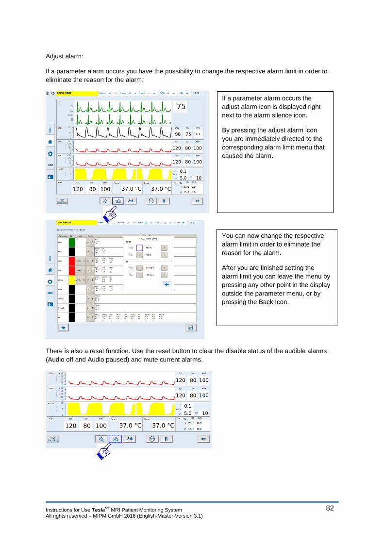
Instructions for Use TeslaM3
MRI Patient Monitoring System All rights reserved – MIPM GmbH 2016 (English-Master-Version 3.1)
82
Adjust alarm:
If a parameter alarm occurs you have the possibility to change the respective alarm limit in order to
eliminate the reason for the alarm.
There is also a reset function. Use the reset button to clear the disable status of the audible alarms
(Audio off and Audio paused) and mute current alarms.
If a parameter alarm occurs the
adjust alarm icon is displayed right
next to the alarm silence icon.
By pressing the adjust alarm icon
you are immediately directed to the
corresponding alarm limit menu that
caused the alarm.
You can now change the respective
alarm limit in order to eliminate the
reason for the alarm.
After you are finished setting the
alarm limit you can leave the menu by
pressing any other point in the display
outside the parameter menu, or by
pressing the Back Icon.

Instructions for Use TeslaM3
MRI Patient Monitoring System All rights reserved – MIPM GmbH 2016 (English-Master-Version 3.1)
83
The Global Audio Alarm OFF/ON setting: This function is restricted to responsible organization and protected via a password. Inactivation/activation of alarm signals at remote monitor: This function is restricted to responsible organization and protected via a password.
Warning: A potential hazard can exist if different alarm pre-sets are used. Please check the current alarm pre-set to ensure the pre-set is appropriate to use on each patient.
5.6. ECG and heart rate
TeslaM3
offers the following ECG functions:
- 3 leads ECG trace
- Digital artifact filter against impact of MRI gradients
- Display of the heart rate per minute
- Arrhythmia events: Cardiac arrest, Bradycardia, Tachycardia
The electrodes attached to the patient measure the electrical impulses from the heart. The monitor
processes, amplifies and displays the measured impulses on the main screen.
You may use a 3 lead ECG plus one reference lead. With this setup the following ECG leads are
available: I, II and III. The reference lead cannot be used as an ECG lead.
The value will be displayed in the ECG parameter box.

Instructions for Use TeslaM3
MRI Patient Monitoring System All rights reserved – MIPM GmbH 2016 (English-Master-Version 3.1)
84
5.6.1. Remarks ECG during MRI examination
During an MRI examination the ECG is exposed to strong interferences caused by the gradient system
of the MRI scanner. TeslaM3
is equipped with a digital artifact filter. The filter enables an applicable
ECG also during the scanning sequences. However the filter cannot eliminate all artifacts imposed by
the scanner which leads to small deviances in the ECG reading from time to time.
Special attention needs to be paid to the placement of the ECG electrodes and the preparation
of the patient’s skin!
Do only use MRI compatible ECG electrodes! You can get details from the manufacturer of the electrodes. The MRI compatible ECG electrodes recommended by MIPM can be found in the accessories list in this user manual.
Due to the environment in the MRI room the ECG of this monitor is susceptible to artifacts. Thus an advanced cardiac diagnostic cannot be performed with the Tesla
M3®. If a patient is at
risk of specific cardiac illnesses an appropriate diagnostic should be performed before or after the MRI scan.
The ECG cable is a conductive cable and should never be placed in loops. Loops in conductive cables may cause induction of current and heating of the cable.
0.15 mV is the minimum amplitude patients ECG signal required for the measurement. The drop below this value can lead to inaccurate measurements.
Due to electronic components in the enclosure of the ECG sensor the homogeneity of the
magnetic field could be disturbed. Interference on the images could be the consequence. Please place the enclosure of the sensor out of the examination area with the spacing of at least 40 cm.
The device is not able to ensure adequate ST-segment reproduction The Tesla
M3 is not intended to be used for patients with a pacemaker.
The enclosure of the ECG Sensor is not intended to have a direct contact with the bare skin of a patient.
Conductive parts of electrodes and associated connectors for applied parts, including the neutral electrode, should not contact any other conductive parts including earth.

Instructions for Use TeslaM3
MRI Patient Monitoring System All rights reserved – MIPM GmbH 2016 (English-Master-Version 3.1)
85
5.6.2. ECG electrodes and skin preparation
To ensure optimal results in ECG monitoring during MRI examination MIPM recommends preparing
the patient’s skin with an abrasive ECG gel. The contact between the ECG pad and the skin has a
strong influence on the quality of the ECG readings.
Very hairy patients have to be shaved at the chest.
Skin preparation:
An essential element of the ECG Quality is the electrical resistance between the ECG pad and the
skin. To ensure a minimal resistance the skin should be prepared before the ECG electrodes are
placed. Please use the NUPREP gel or another abrasive ECG gel.
Remove lotions or fluids from the skin before placing the ECG pads.
Placing the ECG electrodes (left breast is in the center)
Alternative placing the ECG electrodes (near to body middle)
Rub the NUPREP gel in the
skin gently using a paper
towel.
Prepare a rather large area
(red circle). This leaves you
some freedom when
placing the electrodes.
Remove remaining gel from
the skin and place the ECG
pads as shown in the
picture.
RA (red dot)
Ref line (blue clamp)
LA (yellow dot)
LL (green dot)
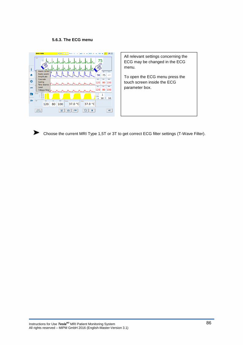
Instructions for Use TeslaM3
MRI Patient Monitoring System All rights reserved – MIPM GmbH 2016 (English-Master-Version 3.1)
86
5.6.3. The ECG menu
Choose the current MRI Type 1,5T or 3T to get correct ECG filter settings (T-Wave Filter).
All relevant settings concerning the
ECG may be changed in the ECG
menu.
To open the ECG menu press the
touch screen inside the ECG
parameter box.

Instructions for Use TeslaM3
MRI Patient Monitoring System All rights reserved – MIPM GmbH 2016 (English-Master-Version 3.1)
87
5.6.4. Setting the alarm limits
Press the alarm limits bar in the ECG menu.
5.6.5. Choosing the ECG lead
Press the Lead bar in the ECG menu.
Color code of the ECG cable connectors: the connectors of the ECG lead are marked with the
international accepted color code.
Europe: Red – RA, Yellow – LA, Green – LL, Blue – Reference electrode
USA: White – RA, Green – LA, Red – LL, Blue – Reference electrode
If the configuration as shown in the picture above is chosen (White – RA, Green – LA, Red – LL)
select lead II.
In the sub menu „Alarm limits“ you can
change the upper and lower heart rate limit
by pressing the +/- icons. Pressing the icon
once changes the value by 1 bpm. Holding
the icon changes the values faster.
To exit the Alarm limits menu press the back
icon.
Chose the favoured lead by pressing
the respective icon in the sub menu.
To exit the ECG lead menu press the
back icon.
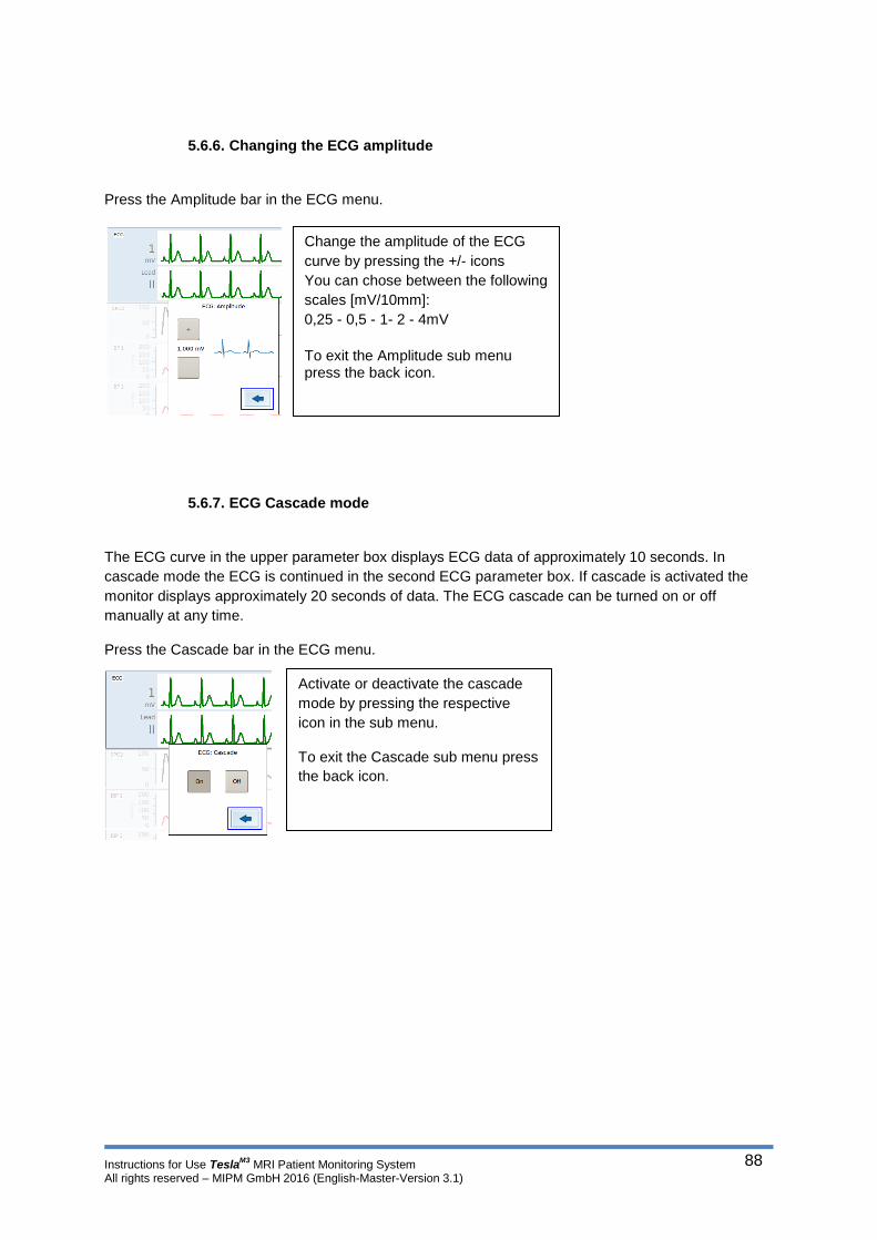
Instructions for Use TeslaM3
MRI Patient Monitoring System All rights reserved – MIPM GmbH 2016 (English-Master-Version 3.1)
88
5.6.6. Changing the ECG amplitude
Press the Amplitude bar in the ECG menu.
5.6.7. ECG Cascade mode
The ECG curve in the upper parameter box displays ECG data of approximately 10 seconds. In
cascade mode the ECG is continued in the second ECG parameter box. If cascade is activated the
monitor displays approximately 20 seconds of data. The ECG cascade can be turned on or off
manually at any time.
Press the Cascade bar in the ECG menu.
Change the amplitude of the ECG
curve by pressing the +/- icons
You can chose between the following
scales [mV/10mm]:
0,25 - 0,5 - 1- 2 - 4mV
To exit the Amplitude sub menu press the back icon.
Activate or deactivate the cascade
mode by pressing the respective
icon in the sub menu.
To exit the Cascade sub menu press
the back icon.

Instructions for Use TeslaM3
MRI Patient Monitoring System All rights reserved – MIPM GmbH 2016 (English-Master-Version 3.1)
89
5.6.8. Choosing the pulse tone source
The pulse tone may be created by the ECG or the SpO2 readings.
Press the Tone Source bar in the ECG menu.
A pulse tone is only generated if the parameter of the selected tone source is measured. e.g. If ECG is selected as tone source and the ECG is not connected to the patient the monitor will not generate a pulse tone.
5.6.9. Cardiac Gating function
The TeslaM3
supports ECG triggered MRI examinations. You can connect the TeslaM3
to the gating
interface of the MRI scanner in order to synchronize the scanning sequences with the ECG of the
monitor.
Every QRS complex (trigger point = R) creates a trigger signal which can be used to align the scanner
with the patient’s heart beat. For more detailed information about the trigger signal please contact your
local service partner or MIPM.
Press the Gating bar in the ECG menu.
Press the ECG icon if the pulse ton should be generated by the ECG and the SpO2 icon if the pulse tone should be emitted by the SpO2 reading.
Only one tone source can be selected!
To exit the tone source sub menu press the back icon.
Chose the source for the trigger signal by
pressing the respective icon in the sub menu.
By pressing Off the gating function is
deactivated.
To exit the Gating sub menu press the back
icon.

Instructions for Use TeslaM3
MRI Patient Monitoring System All rights reserved – MIPM GmbH 2016 (English-Master-Version 3.1)
90
5.7. SpO2 Monitoring
SpO2 monitoring is a non-invasive method to determine the oxygen saturation of the arterial blood as
well as the pulse rate. SpO2 is indicated as functional oxygen saturation.It has been calibrated
exemplary. A sensor (in general attached to the finger) measures the absorption of infrared light going
through the tissue caused by oxyhemoglobin. The light received by the sensor is transformed in a
signal which is processed by the monitor.
The TeslaM3
offers the following monitoring parameters based on SpO2 monitoring.
Display of the SpO2 wave form
Calculation of the pulse rate
Alarm if the oxygen saturation violates a preset alarm limit
Alarm if the pulse rate violates a preset alarm limit
Alarm signal generation delay, alarm condition delay, data update period, data averaging and other signal processing effect displayed and transmitted SpO2 and pulse rate data. A SpO2 or a pulse rate change is displayed within 30 seconds. Because pulse oximeter equipment measurements are statistically distributed, only about two-thirds of pulse oximeter equipment measurements can be expected to fall within ±Arms of the value measured by a co-oximeter.
SpO2 readings strongly depend on the correct placement of the sensor and the condition of the patient. Shiver, strong movements, or inhalation of smoke may cause incorrect measurements. If SpO2 readings seem to be incorrect check the oxygen saturation values with an alternative clinically proven method like blood gas analysis.
You may use the SpO2 sensor on adults, pediatrics and neonates. Do only use original MIPM SpO2 sensors. The use of any other SpO2 sensor not approved by MIPM may lead to incorrect measurements!
Misapplication of the SpO2 sensor with excessive pressure for prolonged periods can induce pressure injury.
To leave the ECG parameter menu
press any place outside the ECG
parameter box in the main screen.

Instructions for Use TeslaM3
MRI Patient Monitoring System All rights reserved – MIPM GmbH 2016 (English-Master-Version 3.1)
91
Misapplication of a pulse oximeter probe with excessive pressure for prolonged periods can induce pressure injury. Check sensors periodically (recommended is at least every four hours). Move the sensor if there is any sign of skin irritation or impaired circulation. We recommend a maximum application time of 4 hours with the wireless pulse oximetry sensor POAP2 in one place
The enclosure of the SpO2 Sensor is not intended to have a direct contact with the bare skin of a patient.
5.7.1. Remarks SpO2 monitoring during MRI examination
The sensor cable is made of optic fibers. Thus the sensor can be used in the MRI environment without
causing artifacts or being attracted by the scanner. Please handle the sensor carefully! Do not kink or
wind up the sensor cable. Do not step on the sensor cable!
If the sensor is not in use please place it in the charging bracket on the back side of the monitor.
Avoid direct contact of the sensor with the inside wall of the bore. During the MRI examination the scanner produces heavy vibrations which may disturb the functioning of the SpO2 sensor und thus lead to incorrect SpO2 readings. Place the sensor on top of the patient or between the legs of the patient.
Do not place the sensor under a receiver coil of the scanner. This may lead to bad connection between the sensor and the Tesla
M3 and bad image quality.
Due to electronic components in the enclosure of the SpO2 sensor the homogeneity of the magnetic field could be disturbed. Interference on the images could be the consequence. Please place the enclosure of the sensor out of the examination area with the spacing of at least 40 cm.
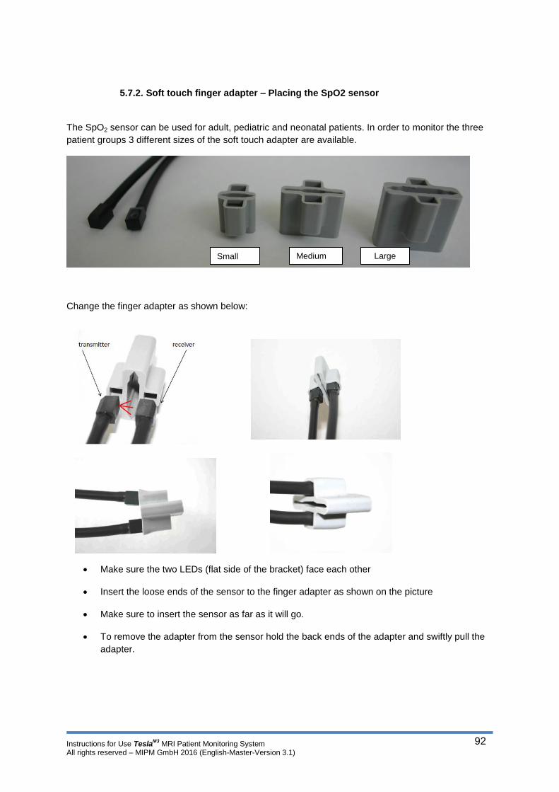
Instructions for Use TeslaM3
MRI Patient Monitoring System All rights reserved – MIPM GmbH 2016 (English-Master-Version 3.1)
92
5.7.2. Soft touch finger adapter – Placing the SpO2 sensor
The SpO2 sensor can be used for adult, pediatric and neonatal patients. In order to monitor the three
patient groups 3 different sizes of the soft touch adapter are available.
Change the finger adapter as shown below:
Make sure the two LEDs (flat side of the bracket) face each other
Insert the loose ends of the sensor to the finger adapter as shown on the picture
Make sure to insert the sensor as far as it will go.
To remove the adapter from the sensor hold the back ends of the adapter and swiftly pull the
adapter.
Large Medium Small

Instructions for Use TeslaM3
MRI Patient Monitoring System All rights reserved – MIPM GmbH 2016 (English-Master-Version 3.1)
93
Correct placement of the SpO2 sensor is vital for successful SpO2 monitoring!
You can now insert the patient’s finger from both sides of the finger adapter. Make sure that the finger
nail faces the transmitter LED (see picture). The finger should not stick out of the sensor regardless
from which side the finger was inserted. This way you can ensure that both, transmitter and receiver
LED are in the middle of the finger nail thereby ensuring an optimal signal.
Successful SpO2 monitoring:
Please observe the following advice:
Always place the sensor on an extremity with good perfusion
Do not place the sensor on an extremity where perfusion may be compromised, e.g. through a
blood pressure cuff
Do not fix the sensor too tight using tapes or clamps
Do not fix the sensor to an extremity where electrical interferences may occur
Do always read the user manual before using the SpO2 sensor
Do not open the housing of the SpO2 sensor. This is only allowed to technical personnel authorized by MIPM. Unauthorized opening of the sensor housing leads to loss of any warranty claims and may damage the sensor! The sensor is equipped with a rechargeable Lithium polymer battery. Do not remove the battery! Broken sensors may not be disposed in the regular waste. If a sensor has to be replaced dispose the broken sensor through an authorized person or send the sensor back to MIPM or an authorized service partner!

Instructions for Use TeslaM3
MRI Patient Monitoring System All rights reserved – MIPM GmbH 2016 (English-Master-Version 3.1)
94
5.7.3. The SpO2 menu
5.7.4. Setting the alarm limits
Press the alarm limits bar in the SpO2 menu.
5.7.5. Changing the SpO2 scaling
The SpO2 module has an auto scaling function. The scaling of the SpO2 waveform cannot be changed
manually.
All relevant settings concerning the
SpO2 may be changed in the SpO2
menu.
To enter the SpO2 menu press the
touch screen somewhere inside the
SpO2 parameter box.
Change the respective alarm limit by pressing the +/- icons. Pressing the icons once changes the value by 1. Holding the icons changes the values faster.
To exit the alarm limits sub menu press the back icon.
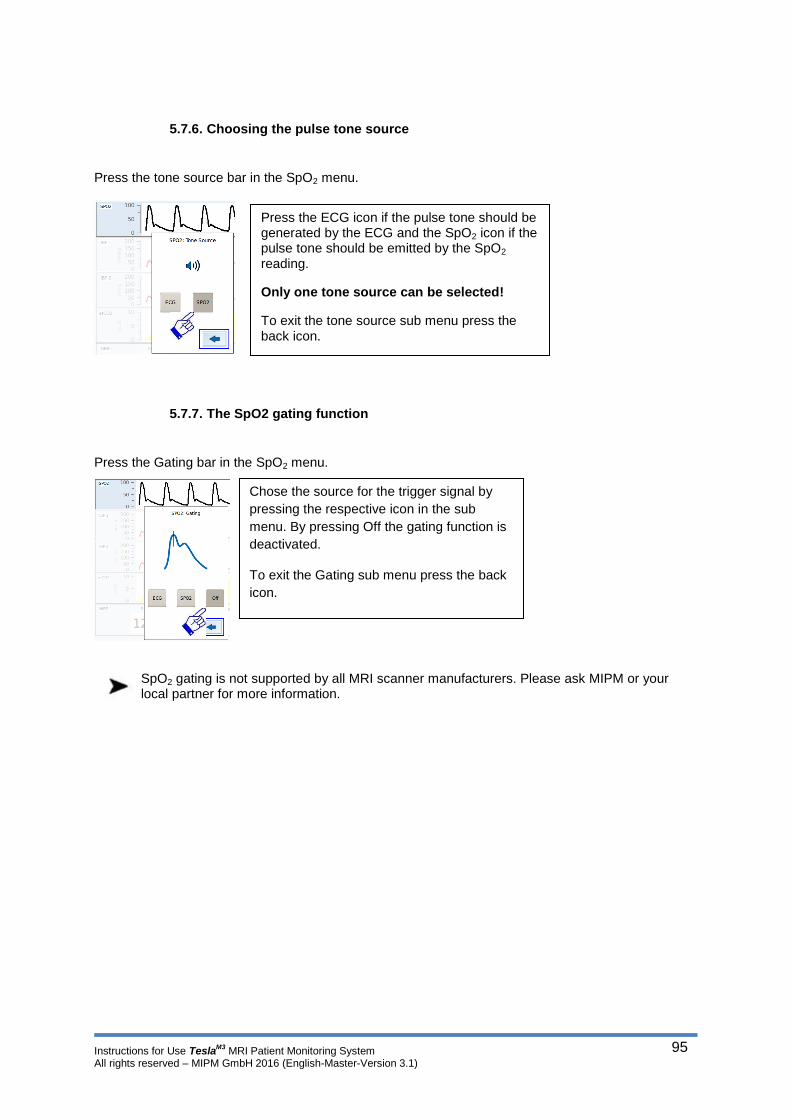
Instructions for Use TeslaM3
MRI Patient Monitoring System All rights reserved – MIPM GmbH 2016 (English-Master-Version 3.1)
95
5.7.6. Choosing the pulse tone source
Press the tone source bar in the SpO2 menu.
5.7.7. The SpO2 gating function
Press the Gating bar in the SpO2 menu.
SpO2 gating is not supported by all MRI scanner manufacturers. Please ask MIPM or your local partner for more information.
Press the ECG icon if the pulse tone should be generated by the ECG and the SpO2 icon if the pulse tone should be emitted by the SpO2 reading.
Only one tone source can be selected!
To exit the tone source sub menu press the back icon.
Chose the source for the trigger signal by
pressing the respective icon in the sub
menu. By pressing Off the gating function is
deactivated.
To exit the Gating sub menu press the back
icon.
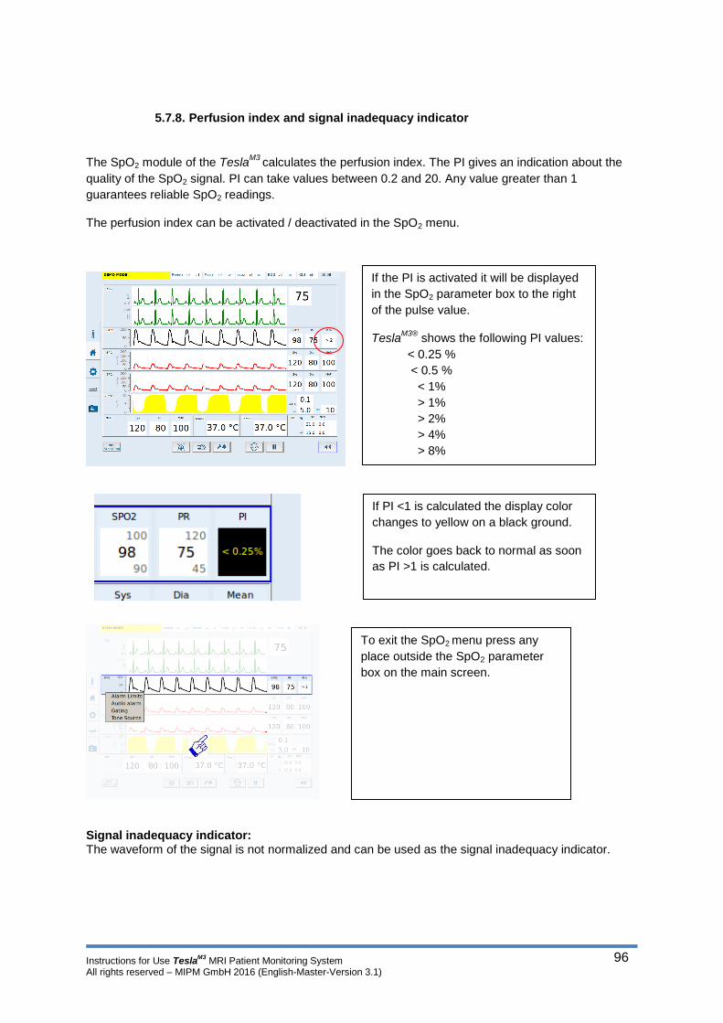
Instructions for Use TeslaM3
MRI Patient Monitoring System All rights reserved – MIPM GmbH 2016 (English-Master-Version 3.1)
96
5.7.8. Perfusion index and signal inadequacy indicator
The SpO2 module of the TeslaM3
calculates the perfusion index. The PI gives an indication about the
quality of the SpO2 signal. PI can take values between 0.2 and 20. Any value greater than 1
guarantees reliable SpO2 readings.
The perfusion index can be activated / deactivated in the SpO2 menu.
Signal inadequacy indicator: The waveform of the signal is not normalized and can be used as the signal inadequacy indicator.
If the PI is activated it will be displayed
in the SpO2 parameter box to the right
of the pulse value.
TeslaM3®
shows the following PI values:
< 0.25 %
< 0.5 %
< 1%
> 1%
> 2%
> 4%
> 8%
If PI <1 is calculated the display color
changes to yellow on a black ground.
The color goes back to normal as soon
as PI >1 is calculated.
To exit the SpO2 menu press any
place outside the SpO2 parameter
box on the main screen.

Instructions for Use TeslaM3
MRI Patient Monitoring System All rights reserved – MIPM GmbH 2016 (English-Master-Version 3.1)
97
5.8. Noninvasive blood pressure (NIBP)
Before monitoring noninvasive blood pressure please read the NIBP safety advice (below).
Before monitoring pediatric or neonatal patients observe the following advice: Chose correct cuff size! Chose pediatric or neonatal patient mode. This protects children from excess cuff pressure! MIPM recommends NIBP calibration as a part of the regular safety check and additionally if the accuracy of the NIBP measurements is at question. NIBP calibration should only be carried out by a trained technical professional.
TeslaM3
receives noninvasive blood pressure values from the NIBP module and displays the values in the main screen. Blood pressure readings with this monitor are generated using the oscillometric method. The measurements comply with intra-arterial measurements within the guidelines of the Association for Advancement of Medical Instrumentation, Electronic Sphygmomanometers (AAMI/ANSI SP-10) If a pressure value cannot be generated due to patient movements or improper cuff placement the cuff
is deflated and a second attempt is carried out.
TeslaM3
displays the systolic, diastolic and mean NIBP values (mmHg) in the NIBP parameter box.
The quality of NBP monitoring depends largely on the quality of the signals received by the monitor.
For this reason, it is important to select the correct cuff size for your patient. Cuff sizes are clearly
marked on the cuff. Measure the circumference of your patient’s limb. Use only MIPM-approved cuffs
with your monitor (see the chapter Accessories).
If a malfunction is detected by the monitor or unexpected readings are obtained, the operator should
observe details of alarm system. For further information refer to section 5.5 Alarms.
NIBP safety advice:
The cuff should be placed on the height of the heart. For any deviance of 2 cm (1 inch) above that height 1.4 mmHg should be added to the measurement value. For any deviance of 2 cm (1 inch) below that height 1.4 mmHg should be subtracted from the measurement value. The blood pressure reading can also be affected by the measurement site, the position of the patient (standing, sitting, lying down), exercise, or the patient’s physiologic condition. The performance of the NBP measure can be affected by extremes of temperature, humidity and altitude. The NIBP tube should not be kinked or blocked! The cuff should not be placed on an extremity that is already used for infusions.

Instructions for Use TeslaM3
MRI Patient Monitoring System All rights reserved – MIPM GmbH 2016 (English-Master-Version 3.1)
98
In some cases, rapid and prolonged measurements can result in petechia, ischemia, purpura or neuropathy. MIPM recommends that you apply the cuff appropriately and that you check the cuff site regularly when monitoring at frequent intervals or over extended periods of time. In addition, check the patient for signs of impeded blood flow in the limb. The application of the CUFF and its pressurization on any limb where intravascular access or therapy, or an arterio-venous (A-V) shunt, is present, could result a temporary interference to blood flow and in injury to the patient. The application of the CUFF on the arm on the side of a mastectomy could lead to pressurization. For patients who have had a mastectomy or lumpectomy, do not use the involved arm(s) for NBP if there is lymphedema. Pressurization of the CUFF can temporarily cause loss of function of simultaneously used monitoring ME EQUIPMENT on the same limb. NBP measurements may not be accurate with convulsive patients or patients with tremors. NBP is not intended for use with pregnant, including pre-eclamptic, patients.
CAUTION: Do not allow the tube or cuff to get in contact with fluids. Check the hose and cuff frequently for signs of damage and debris. An obstruction in the hose may cause the cuff to inflate and deflate improperly and may result in inaccurate readings.
NOTES: To obtain accurate blood pressure readings, keep the limb and cuff motionless. To protect patients from extremely high cuff pressures and extended cuff inflation, the cuff deflates automatically in the following conditions:
The cuff pressure exceeds over 300 mmHg in Adult- / Pediatric mode, or over 150 mmHg in neonatal mode.
The measurement takes longer than 2 minutes
A technical alarm has occurred.

Instructions for Use TeslaM3
MRI Patient Monitoring System All rights reserved – MIPM GmbH 2016 (English-Master-Version 3.1)
99
5.8.1. Remarks NIBP during MRI examination
Avoid any contact between the NIBP cuff and the inside wall of the scanner tube. Heavy vibration during the scan may cause false readings or abortion of the measurement. Make sure that the NIBP tube is not kinked through a receiver coil of the scanner. Make sure that the NIBP tube is not placed in the runner of the examination table. During the MRI examination the table of the scanner is subject to movements. This may cause damage of the NIBP tube. Replace defective NIBP tubes immediately to ensure accurate NIBP readings.
5.8.2. The NIBP menu
5.8.3. Setting the alarm limits
Press the Alarm limit bar in the NIBP menu.
All relevant settings concerning the
NIBP may be changed in the NIBP
menu.
To enter the NIBP menu press the
touch screen somewhere inside the
NIBP parameter box.
In the upper part of the menu box you will see a drop down list. Chose Sys, Dia, or Mean according to the limits you want to change.
Change the respective alarm limit by pressing the +/- icons. Pressing the icons once changes the value by 1. Holding the icons changes the values faster.
To exit the alarm limits sub menu press the back icon.

Instructions for Use TeslaM3
MRI Patient Monitoring System All rights reserved – MIPM GmbH 2016 (English-Master-Version 3.1)
100
5.8.4. Setting the NIBP measurement interval
Press the Interval bar in the NIBP menu.
5.8.5. Automatic / Manual measurements
Press the Automatic bar in the NIBP menu
Press the +/- icons, to increase / decrease the measurement interval. The following intervals are available: 1, 2, 5, 10, 15, 30 minutes.
To exit the Interval sub menu press the back icon.
To exit the NIBP menu press any
place outside the NIBP parameter
box on the main screen.
Chose Automatic for automatic interval
measurements and Manual for manual
NIBP measurements.
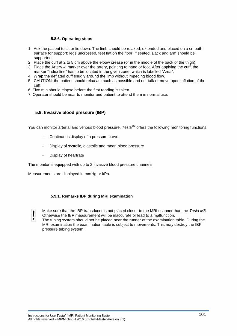
Instructions for Use TeslaM3
MRI Patient Monitoring System All rights reserved – MIPM GmbH 2016 (English-Master-Version 3.1)
101
5.8.6. Operating steps
1. Ask the patient to sit or lie down. The limb should be relaxed, extended and placed on a smooth
surface for support: legs uncrossed, feet flat on the floor, if seated. Back and arm should be supported.
2. Place the cuff at 2 to 5 cm above the elbow crease (or in the middle of the back of the thigh). 3. Place the Artery «. marker over the artery, pointing to hand or foot. After applying the cuff, the
marker “index line” has to be located in the given zone, which is labelled “Area”. 4. Wrap the deflated cuff snugly around the limb without impeding blood flow. 5. CAUTION: the patient should relax as much as possible and not talk or move upon inflation of the
cuff. 6. Five min should elapse before the first reading is taken. 7. Operator should be near to monitor and patient to attend them in normal use.
5.9. Invasive blood pressure (IBP)
You can monitor arterial and venous blood pressure. TeslaM3
offers the following monitoring functions:
- Continuous display of a pressure curve
- Display of systolic, diastolic and mean blood pressure
- Display of heartrate
The monitor is equipped with up to 2 invasive blood pressure channels.
Measurements are displayed in mmHg or kPa.
5.9.1. Remarks IBP during MRI examination
Make sure that the IBP transducer is not placed closer to the MRI scanner than the Tesla M3. Otherwise the IBP measurement will be inaccurate or lead to a malfunction. The tubing system should not be placed near the runner of the examination table. During the MRI examination the examination table is subject to movements. This may destroy the IBP pressure tubing system.

Instructions for Use TeslaM3
MRI Patient Monitoring System All rights reserved – MIPM GmbH 2016 (English-Master-Version 3.1)
102
5.9.2. Use of IBP transducers
The quality of pressure monitoring depends on the quality of the signals received by the monitor. To
maximize the strength of the pressure signal when it reaches the transducer, assemble the tubing sys-
tem carefully following the application techniques of your hospital. Noise and motion artifact as well as
air bubbles in the tubing system distort the signal and give inaccurate measurements. Consider the
following:
1. Select a high pressure tubing system (compliant tubing dampens and distorts the signal). 2. Select the shortest possible length of tubing to preserve signal strength and minimize motion
artifact. 3. Follow your hospital procedures in assembling the tubing system.
Tubing, transducers or cables that have changes in performance as a result of ageing and environmental conditions must be considered critically. The manufacturer’s instructions as replacing of affected parts must be followed. MIPM recommends the replacing of the interface cable in the event of changes in performance as a result of ageing and environmental conditions.
You may use standard IBP transducers with the Tesla
M3. MIPM tested and approved a choice of IBP
transducers. A list with approved IBP transducers can be found the accessories section. A cable that
matches your standard transducer is included in the sales package.
The TeslaM3
may be operated during defibrillation but the parameter values may be biased for a short period. To ensure patient safety, interference free performance of the Tesla
M3 do only use original MIPM accessories such as IBP Interface Cable and original
IBP transducers are listed in the accessories section.
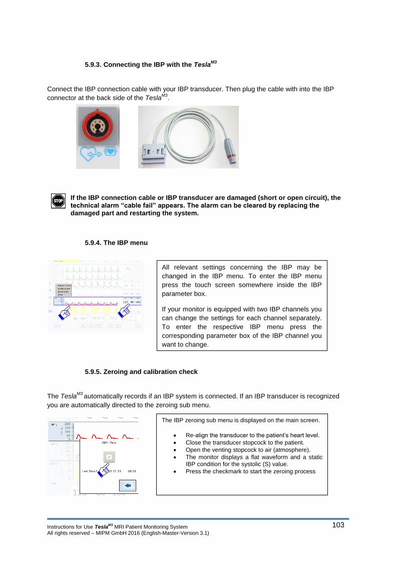
Instructions for Use TeslaM3
MRI Patient Monitoring System All rights reserved – MIPM GmbH 2016 (English-Master-Version 3.1)
103
5.9.3. Connecting the IBP with the TeslaM3
Connect the IBP connection cable with your IBP transducer. Then plug the cable with into the IBP
connector at the back side of the TeslaM3
.
If the IBP connection cable or IBP transducer are damaged (short or open circuit), the technical alarm “cable fail” appears. The alarm can be cleared by replacing the damaged part and restarting the system.
5.9.4. The IBP menu
5.9.5. Zeroing and calibration check
The TeslaM3
automatically records if an IBP system is connected. If an IBP transducer is recognized
you are automatically directed to the zeroing sub menu.
All relevant settings concerning the IBP may be
changed in the IBP menu. To enter the IBP menu
press the touch screen somewhere inside the IBP
parameter box.
If your monitor is equipped with two IBP channels you
can change the settings for each channel separately.
To enter the respective IBP menu press the
corresponding parameter box of the IBP channel you
want to change.
The IBP zeroing sub menu is displayed on the main screen.
Re-align the transducer to the patient’s heart level.
Close the transducer stopcock to the patient.
Open the venting stopcock to air (atmosphere).
The monitor displays a flat waveform and a static IBP condition for the systolic (S) value.
Press the checkmark to start the zeroing process
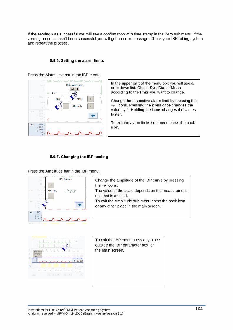
Instructions for Use TeslaM3
MRI Patient Monitoring System All rights reserved – MIPM GmbH 2016 (English-Master-Version 3.1)
104
If the zeroing was successful you will see a confirmation with time stamp in the Zero sub menu. If the zeroing process hasn’t been successful you will get an error message. Check your IBP tubing system and repeat the process.
5.9.6. Setting the alarm limits
Press the Alarm limit bar in the IBP menu.
5.9.7. Changing the IBP scaling
Press the Amplitude bar in the IBP menu.
In the upper part of the menu box you will see a drop down list. Chose Sys, Dia, or Mean according to the limits you want to change.
Change the respective alarm limit by pressing the +/- icons. Pressing the icons once changes the value by 1. Holding the icons changes the values faster.
To exit the alarm limits sub menu press the back icon.
Change the amplitude of the IBP curve by pressing
the +/- icons.
The value of the scale depends on the measurement
unit that is applied.
To exit the Amplitude sub menu press the back icon
or any other place in the main screen.
To exit the IBP menu press any place
outside the IBP parameter box on
the main screen.

Instructions for Use TeslaM3
MRI Patient Monitoring System All rights reserved – MIPM GmbH 2016 (English-Master-Version 3.1)
105
5.10. Capnography
The capnography module is operational after 15 seconds. Full accuracy is reached after approximately
5 minutes.
The capnography module uses infrared spectroscopy (NDIR, "non-dispersive infrared"), to determine the content of CO 2 in a mixture of gases, normally the mixture that is present in the inhaled and exhaled breath of a human. It does this by sampling a specific amount of the gas by a small pump and passing this small sample through a miniature cuvette. The amount of gas the module samples is regulated by a flow sensor. On one side of this cuvette, there is an infrared source that emits a broad band of infra-red radiation. This radiation is passed through a filter that only lets through a radiation of a specific wavelength. This wavelength is one of the specific wavelengths where CO 2 molecules absorb energy in the infrared band. On the other side of the cuvette, a receiver measures the amount of infrared radiation that can pass the cuvette. The higher the CO 2 content in the gas, the more radiation is absorbed in the cuvette. The relation of absorption to CO 2 content is nonlinear, highly temperature and pressure sensitive. The module therefore also measures these two parameters and corrects the measured values accordingly by proprietary algorithms. The capnography module is thus equipped with automatic barometer pressure compensation. Humidity and condensate destroy the measuring cell. The CO2 Water Trap must be used always to avoid that. The leaks or internal venting can have effects on stated performance. E.g. when secondary air is drown with ~0% CO2, the displayed value can be too low. How much exactly depends on the mixing ratio, and consequently on the size of the leak. With cyclic pressure, the extraction rate is no longer true when the pressure changes quickly. In extreme cases, the pump switches off because the controller realizes via the flow sensor that it cannot adjust the extraction rate. The calibration of the module is STPD (standard temperature, pressure and dry).
During the boot process of the TeslaM3
the capnography module performs an automatic zero calibration using ambient air and a CO2 absorber. A manual calibration is recommended every 2000 hours of operation or 24 weeks. (Depending on what happens first).
The CO2 calibration should be part of the regular safety check of the TeslaM3
. The calibration should only be performed by a trained technical professional!
Except for the capnogram, all values are sent once per second. The capnogram is sent with 50 or 25
values per second.
The CO2 measurements can be displayed in volume % or mmHg.
Gas outlet:
If there is a gas connection to an anesthesia machine, the gas recirculation should be used in order to avoid an increased concentration of anesthetic gas in the operating room. Use the gas outlet of the module for that. Use bacteria filter to avoid the cross-contamination and gas samples for gas recirculation from the manufacturer of the anesthesia machine. Perform the connection and its maintenance according the regulations of the manufacturer of the anesthesia machine.

Instructions for Use TeslaM3
MRI Patient Monitoring System All rights reserved – MIPM GmbH 2016 (English-Master-Version 3.1)
106
5.10.1. Adapting the sample rate
The sample rate of the capnography module cannot be set manually. It depends on the selected patient mode.
5.10.2. Installing / removing the water trap
Connect the water trap with the green adapter first to the connector on the back side of the TeslaM3
.
By turning the water trap contra clockwise you can remove it from the connector.
Replace the water trap according to the regulations of the manufacturer.
5.10.3. Connecting the sample gas line
Connect the gas sample line with the free connector on the water trap. On the other end connect the
sample line to the airway connector. You should only use sample lines with LUER Lock connectors.
If a nasal gas sample line is used connect the free end of the line to the water trap. Put the loop around the patient’s head and place the nasal pieces in the nose of the patient.
5.10.4. The capnography menu
All relevant settings concerning the Capnography can
be changed in the capnography menu.
To enter the capnography menu press the touch
screen inside the CO2 parameter box.

Instructions for Use TeslaM3
MRI Patient Monitoring System All rights reserved – MIPM GmbH 2016 (English-Master-Version 3.1)
107
5.10.5. Setting the alarm limits
Press the Alarm limits bar in the capnography menu.
5.10.6. Changing the CO2 scaling
The Capnography module is equipped with an auto scaling function. The amplitude of the CO2 curve cannot be changed manually.
5.10.7. Setting the O2 Concentration
Press the O2 concentration bar in the capnography menu.
At the top of the Sub menu you will find a drop down list. Open the list to choose between iCO2 or etCO2 alarm limits
Change the respective alarm limit by pressing the +/- icons. Pressing the icons once changes the value by 1. Holding the icons changes the values faster.
To exit the alarm limits sub menu press the back icon.
Chose the selected O2 concentration by
pressing the respective value in the sub
menu.
Press the Back Icon to leave the menu.

Instructions for Use TeslaM3
MRI Patient Monitoring System All rights reserved – MIPM GmbH 2016 (English-Master-Version 3.1)
108
5.10.8. Setting the N2O Concentration
Press the N2O concentration bar in the capnography menu.
To exit the Capnography menu any place outside
the CO2 parameter box on the main screen.
Chose the selected N2O concentration
by pressing the respective value in the
sub menu.
Press the Back Icon to leave the menu.
Instructions for Use TeslaM3
MRI Patient Monitoring System All rights reserved – MIPM GmbH 2016 (English-Master-Version 3.1)
109
5.11. Multigas Module
The Multi Gas Module samples breathing gases from adult and pediatric patients in non-, partial- and
total rebreathing systems at a sample flow rate of approximately 200 ml/min. The module measures
inspiratory and expiratory gases and communicates both real-time and derived gas information to the
monitor.
The module is thus equipped with automatic barometer pressure compensation.
If the Multigas module is used in neonatal patient mode please keep in mind: The sample rate of the Multigas module is 200 ml/min. This may affect your decision of the appropriate ventilation mode.
For the measurement of CO2 and volatile anesthetics, the Multi Gas Module draws a small amount of
the patient’s respiratory gas through a measuring chamber. It then shines an infrared light through the
chamber which the sample gas components absorb in different amounts, depending on the gas
concentrations. For the measurement of O2, the Gas module uses a paramagnetic cell that produces a
physical reaction proportional to the O2 concentration.
The displayed gas information is intended to be used by trained and authorized health care professionals only. The Multi Gas Module purges and zeroes itself approximately once every 2 hours. The purging/zeroing cycle lasts no longer than 25 seconds. During this time, the monitor does not update the displayed Gas parameter values on the screen and blanks the etCO2 waveform. The message “Gas Zero in Progress” appears in the message area. Due to the response time of the sensors and the gas sample flow rate, the stated accuracy of O2, CO2, N2O and anesthetic agents is limited by the respiratory rate and by the inspiratory to expiratory ratio (I:E). For details, see the Technical Data appendix.
Do not expose the gas module to mechanical shocks as this would distort the gas measurements.
The presence of organic cleaning solutions or gases containing Freon may adversely impact the accuracy of the Multi Gas Module. Mechanical shocks during the measurement or the presence of other paramagnetic agents can distort measured values of oxygen concentration. The Multi Gas Module is self-zeroing and does not need routine calibration by the clinical staff. However, a yearly check of the Gas calibration components should be performed by authorized technical personnel.
To avoid the risk of explosion, do not use flammable anesthetic agents such as ether and Cyclopropane in the presence of the Multi Gas module. The leaks or internal venting can have effects on stated performance. E.g. when secondary air is drown with ~0% CO2, the displayed value can be too low. How much exactly depends on the mixing ratio, and consequently on the size of the leak.
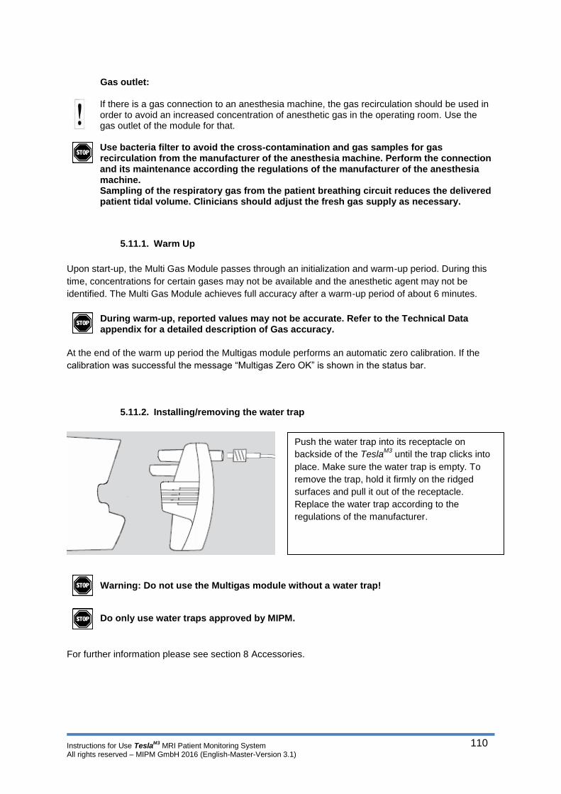
Instructions for Use TeslaM3
MRI Patient Monitoring System All rights reserved – MIPM GmbH 2016 (English-Master-Version 3.1)
110
Gas outlet:
If there is a gas connection to an anesthesia machine, the gas recirculation should be used in order to avoid an increased concentration of anesthetic gas in the operating room. Use the gas outlet of the module for that. Use bacteria filter to avoid the cross-contamination and gas samples for gas recirculation from the manufacturer of the anesthesia machine. Perform the connection and its maintenance according the regulations of the manufacturer of the anesthesia machine. Sampling of the respiratory gas from the patient breathing circuit reduces the delivered patient tidal volume. Clinicians should adjust the fresh gas supply as necessary.
5.11.1. Warm Up
Upon start-up, the Multi Gas Module passes through an initialization and warm-up period. During this
time, concentrations for certain gases may not be available and the anesthetic agent may not be
identified. The Multi Gas Module achieves full accuracy after a warm-up period of about 6 minutes.
During warm-up, reported values may not be accurate. Refer to the Technical Data appendix for a detailed description of Gas accuracy.
At the end of the warm up period the Multigas module performs an automatic zero calibration. If the
calibration was successful the message “Multigas Zero OK” is shown in the status bar.
5.11.2. Installing/removing the water trap
Warning: Do not use the Multigas module without a water trap! Do only use water traps approved by MIPM.
For further information please see section 8 Accessories.
Push the water trap into its receptacle on
backside of the TeslaM3
until the trap clicks into
place. Make sure the water trap is empty. To
remove the trap, hold it firmly on the ridged
surfaces and pull it out of the receptacle.
Replace the water trap according to the
regulations of the manufacturer.
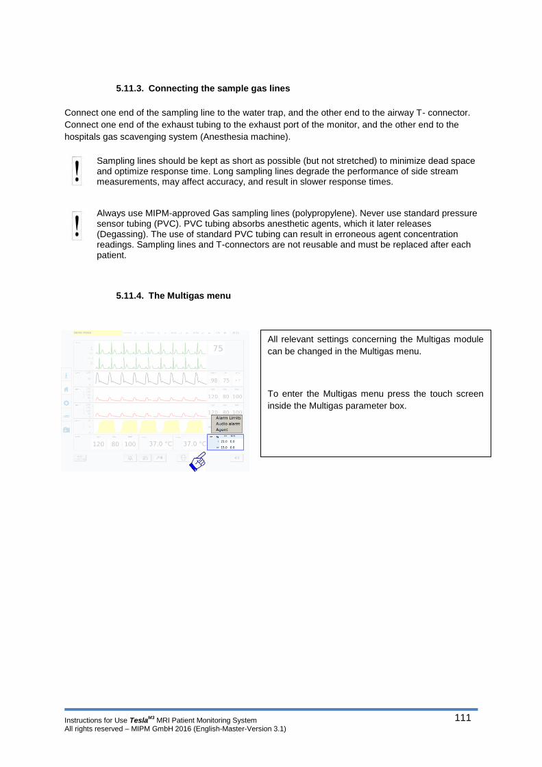
Instructions for Use TeslaM3
MRI Patient Monitoring System All rights reserved – MIPM GmbH 2016 (English-Master-Version 3.1)
111
5.11.3. Connecting the sample gas lines
Connect one end of the sampling line to the water trap, and the other end to the airway T- connector.
Connect one end of the exhaust tubing to the exhaust port of the monitor, and the other end to the
hospitals gas scavenging system (Anesthesia machine).
Sampling lines should be kept as short as possible (but not stretched) to minimize dead space and optimize response time. Long sampling lines degrade the performance of side stream measurements, may affect accuracy, and result in slower response times. Always use MIPM-approved Gas sampling lines (polypropylene). Never use standard pressure sensor tubing (PVC). PVC tubing absorbs anesthetic agents, which it later releases (Degassing). The use of standard PVC tubing can result in erroneous agent concentration readings. Sampling lines and T-connectors are not reusable and must be replaced after each patient.
5.11.4. The Multigas menu
All relevant settings concerning the Multigas module
can be changed in the Multigas menu.
To enter the Multigas menu press the touch screen
inside the Multigas parameter box.
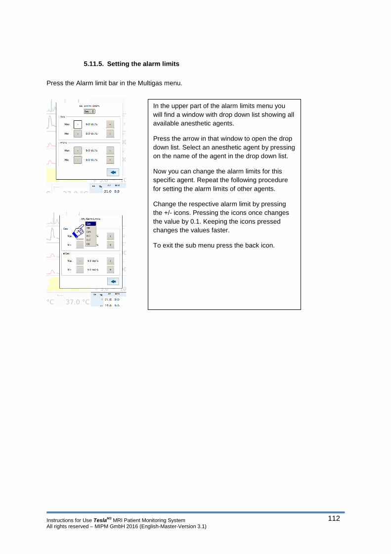
Instructions for Use TeslaM3
MRI Patient Monitoring System All rights reserved – MIPM GmbH 2016 (English-Master-Version 3.1)
112
5.11.5. Setting the alarm limits
Press the Alarm limit bar in the Multigas menu.
In the upper part of the alarm limits menu you
will find a window with drop down list showing all
available anesthetic agents.
Press the arrow in that window to open the drop
down list. Select an anesthetic agent by pressing
on the name of the agent in the drop down list.
Now you can change the alarm limits for this
specific agent. Repeat the following procedure
for setting the alarm limits of other agents.
Change the respective alarm limit by pressing
the +/- icons. Pressing the icons once changes
the value by 0.1. Keeping the icons pressed
changes the values faster.
To exit the sub menu press the back icon.

Instructions for Use TeslaM3
MRI Patient Monitoring System All rights reserved – MIPM GmbH 2016 (English-Master-Version 3.1)
113
5.11.6. Manual or automatic choice of the anesthetic agent
The Multigas module automatically detects anesthetic agents. If the module is operated in automatic
mode the specific agent will be displayed in the Multigas parameter box. The following gases can be
detected:
ISO – Isoflurane
HAL – Halothane
DES – Desflurane
ENF – Enflurane
SEV – Sevoflurane
You also have the choice to select the anesthetic agent manually.
Press the Agent bar in the Multigas menu.
5.12. Temperature measurement
The TeslaM3
determines the body temperature using fiber optic measurement. You can display up to two body temperature measurement channels (surface and intracorporeal). This is a direct mode clinical thermometer. The transient response ≤ 15s.
Chose the requested agent by pressing the
respective bar in the sub menu or chose Auto detect
for automatic agent detection.
To exit the sub menu press the back icon.
To exit the Multigas menu press any place outside
the Multigas parameter box on the main screen.

Instructions for Use TeslaM3
MRI Patient Monitoring System All rights reserved – MIPM GmbH 2016 (English-Master-Version 3.1)
114
5.12.1. Remarks Temperature Measurement during MRI examination:
The sensor cable is made of fiber optics. Do not wind up too close or kink the sensor cable. Make sure that the sensor cable is placed on top of the patient during the MRI examination. Do not place the sensor cable in or near the runner of the examination table as the table is subject to movements during operation. This may destroy the sensor cable. Damaged sensors have to be replaced immediately by authorized technical personnel.
5.12.2. The Temperature menu
5.12.3. Setting the alarm limits
Press the Alarm limit bar in the temperature menu.
All relevant settings concerning the temperature
measurement can be changed in the temperature
menu.
To open the temperature menu press in the
temperature parameter box on the main screen.
If your monitor is equipped with two temperature
channels you can change the settings for each channel
separately. To enter the respective temperature menu
press the corresponding parameter box of the
temperature channel you want to change.
Change the respective alarm limit by pressing the +/- icons. Pressing the icons once changes the value by 1. Holding the icons changes the values faster.
To exit the alarm limits sub menu press the back icon.
To exit the temperature menu press any place
outside the Temperature parameter box on the main
screen.
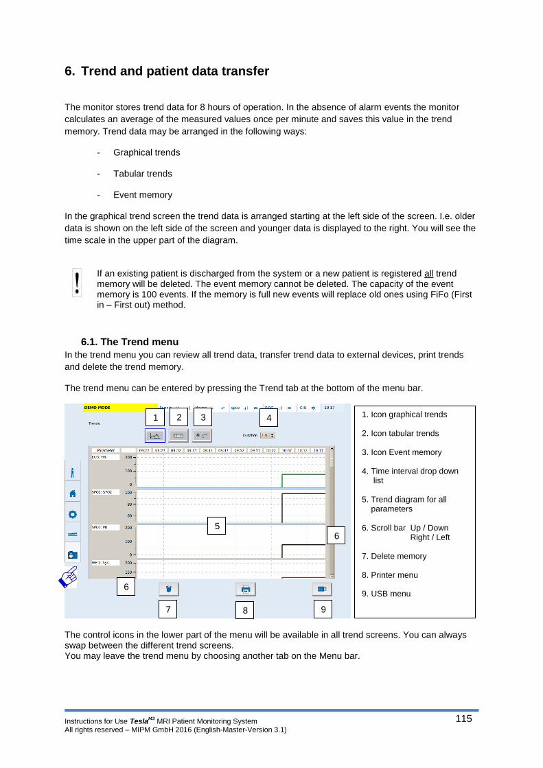
Instructions for Use TeslaM3
MRI Patient Monitoring System All rights reserved – MIPM GmbH 2016 (English-Master-Version 3.1)
115
6. Trend and patient data transfer
The monitor stores trend data for 8 hours of operation. In the absence of alarm events the monitor
calculates an average of the measured values once per minute and saves this value in the trend
memory. Trend data may be arranged in the following ways:
- Graphical trends
- Tabular trends
- Event memory
In the graphical trend screen the trend data is arranged starting at the left side of the screen. I.e. older
data is shown on the left side of the screen and younger data is displayed to the right. You will see the
time scale in the upper part of the diagram.
If an existing patient is discharged from the system or a new patient is registered all trend memory will be deleted. The event memory cannot be deleted. The capacity of the event memory is 100 events. If the memory is full new events will replace old ones using FiFo (First in – First out) method.
6.1. The Trend menu
In the trend menu you can review all trend data, transfer trend data to external devices, print trends
and delete the trend memory.
The trend menu can be entered by pressing the Trend tab at the bottom of the menu bar.
The control icons in the lower part of the menu will be available in all trend screens. You can always swap between the different trend screens. You may leave the trend menu by choosing another tab on the Menu bar.
1 2 3 4
5 6
6
7 8 9
1. Icon graphical trends 2. Icon tabular trends 3. Icon Event memory 4. Time interval drop down list
5. Trend diagram for all parameters
6. Scroll bar Up / Down
Right / Left
7. Delete memory
8. Printer menu 9. USB menu

Instructions for Use TeslaM3
MRI Patient Monitoring System All rights reserved – MIPM GmbH 2016 (English-Master-Version 3.1)
116
6.2. Graphical trends
6.3. Trend table
In the graphical trend screen
every parameter is displayed in
a separate diagram.
You can scroll down with the
bar on the right to see all
parameters.
Press and move the bar up or
down to scroll through the
parameters.
The time interval can be set
between 1 and 8 hours.
Press the window with the drop
down list and chose your time
interval by pressing on the
respective value.
To show the trend table press the table icon
in the upper part of the trend menu.
The time axis always shows 13 intervals.
The size of the intervals change depending
on the time interval that is selected
e.g.
Time interval = 1 hour = 5 minute intervals
Time interval = 2 hours = 10 minute intervals

Instructions for Use TeslaM3
MRI Patient Monitoring System All rights reserved – MIPM GmbH 2016 (English-Master-Version 3.1)
117
6.4. Event memory
The event memory is maintained when the alarm system is powered down or during a total loss of power. The time of powering down is not captured in the log. The capacity of the event memory is 100 events. If the memory is full new events will replace old ones using FiFo (First in – First out) method.
6.5. Printing trend data
The TeslaM3
can be connected to a printer.
(See section 1 – Connecting external devices
Warning! The printer is not MRI compatible. Do not connect the printer to the main unit as long as it is still inside the MRI cabin. Connect the printer to the remote screen in the control room or remove the main unit from the MRI cabin before connecting the printer!
Printing trend data:
1. Connect the printer to the USB interface of the TeslaM3
(left side of the display).
2. Chose the trend screen that you want to print.
3. Press the print icon
4. The trend screen is printed out as a screen shot.
To show the event memory press the event
memory icon in the upper part of the trend
menu.
The event memory stores all parameter
alarms that occurred during the monitoring
period.
The table shows the event with time stamp,
Patient data und the nature of the alarm
including the corresponding parameter
values.
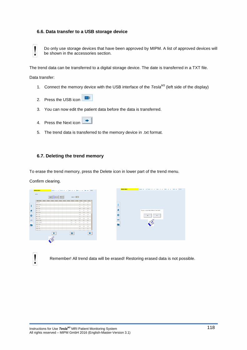
Instructions for Use TeslaM3
MRI Patient Monitoring System All rights reserved – MIPM GmbH 2016 (English-Master-Version 3.1)
118
6.6. Data transfer to a USB storage device
Do only use storage devices that have been approved by MIPM. A list of approved devices will be shown in the accessories section.
The trend data can be transferred to a digital storage device. The date is transferred in a TXT file.
Data transfer:
1. Connect the memory device with the USB interface of the TeslaM3
(left side of the display)
2. Press the USB icon
3. You can now edit the patient data before the data is transferred.
4. Press the Next icon
5. The trend data is transferred to the memory device in .txt format.
6.7. Deleting the trend memory
To erase the trend memory, press the Delete icon in lower part of the trend menu.
Confirm clearing.
Remember! All trend data will be erased! Restoring erased data is not possible.

Instructions for Use TeslaM3
MRI Patient Monitoring System All rights reserved – MIPM GmbH 2016 (English-Master-Version 3.1)
119
7. The Service Menu
Settings and options in the service menu affect sensitive parts of the operating system and thus functioning of the patient monitor. Access to the service menu is only granted to technical personnel authorized by MIPM.
The service menu is pass word secured.

Instructions for Use TeslaM3
MRI Patient Monitoring System All rights reserved – MIPM GmbH 2016 (English-Master-Version 3.1)
120
8. Accessories and applied parts
8.1. ECG Accessories
Item number Description
5300028 Wireless ECG Sensor for TeslaM3 (Defibrillation-proof type CF applied part; multi-use)
5300025 ECG Electrodes for MRI (single-use)
5300006 NUPREP Gel
8.2. SpO2 Accessories
Item number Description
5010100 Wireless Pulse Oximetry Sensor for Tesla M3 (Defibrillation-proof type BF applied part; multi-use)
5010012 SpO2 Adapter - Basic (1x large / 1x medium / 1x small) multi-use
8.3. NIBP Accessories
Item number Description
5100044 NIBP Pressure Hose (multi-use)
5100038 NIBP Pressure cuff 9-15 cm (Defibrillation-proof type BF applied part; multi-use)
5100039 NIBP Pressure cuff 14-21,5 cm (Defibrillation-proof type BF applied part; multi-use)
5100040 NIBP Pressure cuff 20,5-28,5 cm (Defibrillation-proof type BF applied part; multi-use)
5100041 NIBP Pressure cuff 27-35 cm (Defibrillation-proof type BF applied part; multi-use)
5100042 NIBP Pressure cuff 34-44 cm (Defibrillation-proof type BF applied part; multi-use)
5100043 NIBP Pressure cuff 42-52 cm (Defibrillation-proof type BF applied part; multi-use)
8.4. IBP Accessories
Item number Description
5200031 IBP Interface Cable (multi-use)
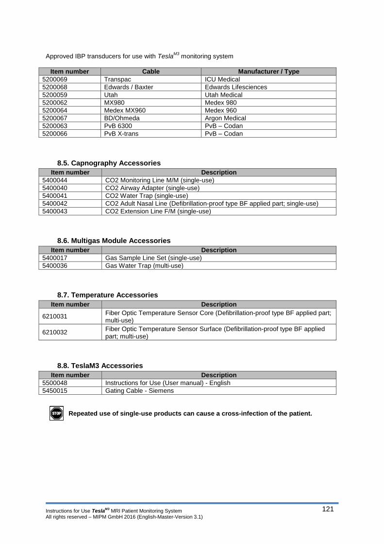
Instructions for Use TeslaM3
MRI Patient Monitoring System All rights reserved – MIPM GmbH 2016 (English-Master-Version 3.1)
121
Approved IBP transducers for use with Tesla
M3 monitoring system
Item number Cable Manufacturer / Type
5200069 Transpac ICU Medical
5200068 Edwards / Baxter Edwards Lifesciences
5200059 Utah Utah Medical
5200062 MX980 Medex 980
5200064 Medex MX960 Medex 960
5200067 BD/Ohmeda Argon Medical
5200063 PvB 6300 PvB – Codan
5200066 PvB X-trans PvB – Codan
8.5. Capnography Accessories
Item number Description
5400044 CO2 Monitoring Line M/M (single-use)
5400040 CO2 Airway Adapter (single-use)
5400041 CO2 Water Trap (single-use)
5400042 CO2 Adult Nasal Line (Defibrillation-proof type BF applied part; single-use)
5400043 CO2 Extension Line F/M (single-use)
8.6. Multigas Module Accessories
Item number Description
5400017 Gas Sample Line Set (single-use)
5400036 Gas Water Trap (multi-use)
8.7. Temperature Accessories
Item number Description
6210031
Fiber Optic Temperature Sensor Core (Defibrillation-proof type BF applied part; multi-use)
6210032
Fiber Optic Temperature Sensor Surface (Defibrillation-proof type BF applied part; multi-use)
8.8. TeslaM3 Accessories
Item number Description
5500048 Instructions for Use (User manual) - English
5450015 Gating Cable - Siemens
Repeated use of single-use products can cause a cross-infection of the patient.

Instructions for Use TeslaM3
MRI Patient Monitoring System All rights reserved – MIPM GmbH 2016 (English-Master-Version 3.1)
122
9. Cleaning and disinfection
Clean the monitor and all accessories after each patient or daily according to your hospitals standard
procedures. MIPM recommends the following cleaning solutions and procedures.
CAUTION: Do not use disinfectants that contain phenol as they can spot plastics. Do not autoclave or clean accessories with strong aromatic, chlorinated, ketone, ether, or ester solvents. Never immerse electrical connectors in liquids.
9.1. Main unit and remote screen
Clean the monitor with gauze moistened in a soap solution.
Dry thoroughly with a lint-free cloth.
Disinfect the monitor with gauze moistened with diluted alcohol or an aldehyde based disin-fectant.
Dry thoroughly with a lint-free cloth.
CAUTION: The material used for the monitor housing enclosure is a surface-coated aluminium. Do not use plastic solvents, sharp tools or abrasives to clean it.
CAUTION: Do not steam autoclave, gas sterilize, or immerse the monitor in water or cleaning solutions. Do not subject the monitor to intense vacuum.
9.2. Patient connection cables and wireless sensors
Clean the patient cables with a gauze pad moistened with a soap solution.
Dry thoroughly with a lint-free cloth.
To disinfect patient cables, wipe the cables with a gauze moistened with diluted alcohol or a aldehyde-based disinfectant
Dry thoroughly with a lint-free cloth.
Do not sterilize the ECG patient cables!
9.3. NIBP cuffs
Wipe the cuff with pad moistened with a soap solution, an aldehyde based disinfectant or an alcohol /
phenol solution.
The cuff may be dipped in the cleaning solution. Make sure that the solution does not flow into the pressure tubing or the cuff itself. This may affect the accurate functioning of the cuff. If cleaning solution enters the pressure tube or the cuff all warranty claims expire.

Instructions for Use TeslaM3
MRI Patient Monitoring System All rights reserved – MIPM GmbH 2016 (English-Master-Version 3.1)
123
9.4. Reusable pressure measurement accessories
Observe the accompanying documentation of the accessories manufacturer.
9.5. Multigas Module / Capnography module
Working with used sample lines, T-connectors and water traps bears the risk of infection. Disposable items should be handled and replaced as recommended by the manufacturer. Please observe your local disposal guidelines or contact MIPM or your local affiliate. Do never open the housing of the monitor during operation. Do not remove the water trap during operation of the module. Do not clean the water trap! Used water traps should be replaced and disposed according to the local disposal guidelines or according the instruction of the water trap manufacturer. The water trap is not reusable.
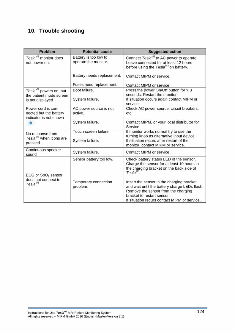
Instructions for Use TeslaM3
MRI Patient Monitoring System All rights reserved – MIPM GmbH 2016 (English-Master-Version 3.1)
124
10. Trouble shooting
Problem Potential cause Suggested action
TeslaM3
monitor does not power on.
Battery is too low to operate the monitor. Battery needs replacement. Fuses need replacement.
Connect TeslaM3
to AC power to operate. Leave connected for at least 12 hours before using the Tesla
M3 on battery.
Contact MIPM or service. Contact MIPM or service.
TeslaM3
powers on, but the patient mode screen is not displayed
Boot failure. System failure.
Press the power On/Off button for > 3 seconds. Restart the monitor. If situation occurs again contact MIPM or service.
Power cord is con-nected but the battery indicator is not shown
AC power source is not active. System failure.
Check AC power source, circuit breakers, etc. Contact MIPM, or your local distributor for Service.
No response from Tesla
M3 when icons are
pressed
Touch screen failure. System failure.
If monitor works normal try to use the turning knob as alternative input device. If situation recurs after restart of the monitor, contact MIPM or service.
Continuous speaker sound
System failure. Contact MIPM or service.
ECG or SpO2 sensor does not connect to Tesla
M3
Sensor battery too low. Temporary connection problem.
Check battery status LED of the sensor. Charge the sensor for at least 10 hours in the charging bracket on the back side of Tesla
M3.
Insert the sensor in the charging bracket and wait until the battery charge LEDs flash. Remove the sensor from the charging bracket to restart sensor. If situation recurs contact MIPM or service.
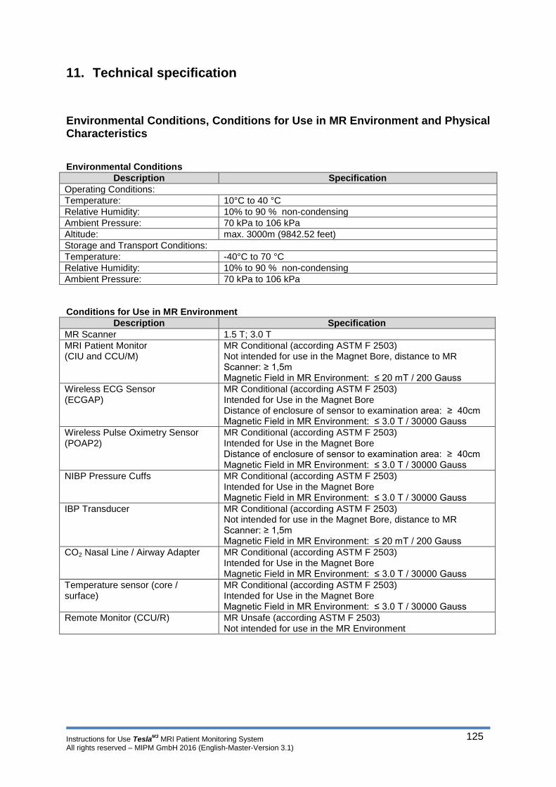
Instructions for Use TeslaM3
MRI Patient Monitoring System All rights reserved – MIPM GmbH 2016 (English-Master-Version 3.1)
125
11. Technical specification
Environmental Conditions, Conditions for Use in MR Environment and Physical Characteristics Environmental Conditions
Description Specification
Operating Conditions:
Temperature: 10°C to 40 °C
Relative Humidity: 10% to 90 % non-condensing
Ambient Pressure: 70 kPa to 106 kPa
Altitude: max. 3000m (9842.52 feet)
Storage and Transport Conditions:
Temperature: -40°C to 70 °C
Relative Humidity: 10% to 90 % non-condensing
Ambient Pressure: 70 kPa to 106 kPa
Conditions for Use in MR Environment
Description Specification
MR Scanner 1.5 T; 3.0 T
MRI Patient Monitor (CIU and CCU/M)
MR Conditional (according ASTM F 2503) Not intended for use in the Magnet Bore, distance to MR Scanner: ≥ 1,5m Magnetic Field in MR Environment: ≤ 20 mT / 200 Gauss
Wireless ECG Sensor (ECGAP)
MR Conditional (according ASTM F 2503) Intended for Use in the Magnet Bore Distance of enclosure of sensor to examination area: ≥ 40cm Magnetic Field in MR Environment: ≤ 3.0 T / 30000 Gauss
Wireless Pulse Oximetry Sensor (POAP2)
MR Conditional (according ASTM F 2503) Intended for Use in the Magnet Bore Distance of enclosure of sensor to examination area: ≥ 40cm Magnetic Field in MR Environment: ≤ 3.0 T / 30000 Gauss
NIBP Pressure Cuffs MR Conditional (according ASTM F 2503) Intended for Use in the Magnet Bore Magnetic Field in MR Environment: ≤ 3.0 T / 30000 Gauss
IBP Transducer MR Conditional (according ASTM F 2503) Not intended for use in the Magnet Bore, distance to MR Scanner: ≥ 1,5m Magnetic Field in MR Environment: ≤ 20 mT / 200 Gauss
CO2 Nasal Line / Airway Adapter MR Conditional (according ASTM F 2503) Intended for Use in the Magnet Bore Magnetic Field in MR Environment: ≤ 3.0 T / 30000 Gauss
Temperature sensor (core / surface)
MR Conditional (according ASTM F 2503) Intended for Use in the Magnet Bore Magnetic Field in MR Environment: ≤ 3.0 T / 30000 Gauss
Remote Monitor (CCU/R) MR Unsafe (according ASTM F 2503) Not intended for use in the MR Environment
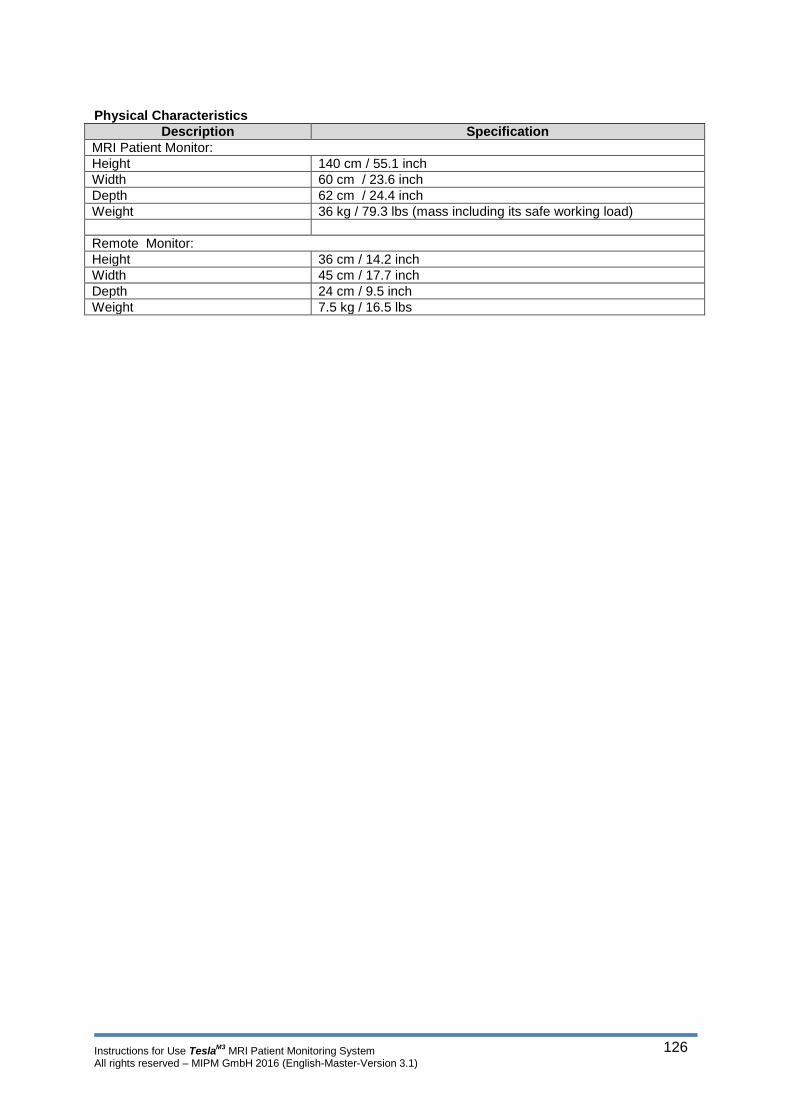
Instructions for Use TeslaM3
MRI Patient Monitoring System All rights reserved – MIPM GmbH 2016 (English-Master-Version 3.1)
126
Physical Characteristics
Description Specification
MRI Patient Monitor:
Height 140 cm / 55.1 inch
Width 60 cm / 23.6 inch
Depth 62 cm / 24.4 inch
Weight 36 kg / 79.3 lbs (mass including its safe working load)
Remote Monitor:
Height 36 cm / 14.2 inch
Width 45 cm / 17.7 inch
Depth 24 cm / 9.5 inch
Weight 7.5 kg / 16.5 lbs

Instructions for Use TeslaM3
MRI Patient Monitoring System All rights reserved – MIPM GmbH 2016 (English-Master-Version 3.1)
127
I) MRI Patient Monitor (CCU/M and CIU)
Display
Description Specification
Screen Size 15 inches ; Ratio 4:3
Screen Type Active Color LCD (Graphical Display)
Resolution 1024 x 768 pixels
User Interface
Description Specification
ON/OFF-Switch ON/OFF-Switch (push-push) with LED Illumination of the integrated LED is on if the device is connected AC power
User / Input device 1 Touchscreen to operate Graphical User Interface (GUI) (all functions like optical encoder)
User / Input device 2 Optical encoder to operate Graphical User Interface (GUI) (all functions like touchscreen)
Patient Modes pre-configured (adult, pediatric, neonate); 1 user configurable
Alarms
Description Specification
Alarm Conditions Physiological Alarms with preset upper and lower alarm limits; Technical Alarms/Information’s
Alarm Indication Visual and Auditory Signals (depending on priority): flashing numeric, changing of color, text messages, adjustable auditory volume
Alarm silence time Auditory Alarm Off/Paused (<120 sec.) with visual alarm indication

Instructions for Use TeslaM3
MRI Patient Monitoring System All rights reserved – MIPM GmbH 2016 (English-Master-Version 3.1)
128
ECG
Description Specification
Accessories MRI electrodes
Sensor Wireless ECG Sensor with high-resistant cable; MRI gradient artifact filtering
Communication with MRI Patient Monitor (CIU)
2.4 GHz wireless
Parameter Heart Rate (HR)
Number of channels 1 channel (Waveform and Numerics)
Sweep Speed of Waveform 25mm/s
Lead selection I; II; III;
Heart Rate Range 30 to 300 BPM (Resolution: 1 BPM)
Heart Rate Accuracy Response to irregular rhythm A1 A2 A3 A4 QRS amplitude of 0,15 mV and QRS duration of 10 ms and a QRS amplitude of 1 mV
± 5 BPM or ±10 % Ventricular bigeminy: 41 BPM Slow alternating ventricular bigeminy: 38-74 BPM Rapid alternating ventricular bigeminy: 96-107 BPM Bidirectional systoles: 99-107 BPM (measurements outside MR Environment; MRI gradient artifact can affect response to irregular rhythm and heart rate accuracy) The device is able to count the correct heart rate at this setting
Heart rate averaging Updating rate of the display T-Wave rejection
8 Beats 100 msec T-Wave rejection up to 0.80 mV with 1 mV QRS Amplitude
Response Time of Heart Rate Meter to Change in Heart Rate
HR change from 80 to 120 BPM: ≤ 6s HR change from 80 to 40 BPM: ≤ 14s
Time to Alarm for Tachycardia:
B1-Vent Tachycardia: <1s
B2-Vent Tachycardia: <1s
Min. Amplitude for ECG patient signal (Sensitivity)
≥ 0.15mV
R-Wave Indicator Waveform and Audible tone on each pulse
Alarm Limit Range 30 to 300 BPM
Degree of protection against electric shock (IEC 60601-1)
Defibrillation-proof type CF applied part
Battery operation of Wireless ECG Sensor:
Type Lithium-Polymer
Battery Operating Time ≥ 8 hours
Battery Charging Time < 10 hours
Battery capacity monitoring Indication of Battery Status / Battery Capacity on Monitor and Sensor
Lead off detection DC Lead-Off detection
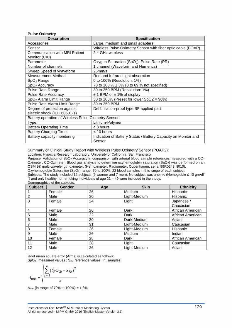
Instructions for Use TeslaM3
MRI Patient Monitoring System All rights reserved – MIPM GmbH 2016 (English-Master-Version 3.1)
129
Pulse Oximetry
Summary of Clinical Study Report with Wireless Pulse Oximetry Sensor (POAP2): Location: Hypoxia Research Laboratory, University of California, San Francisco Purpose: Validation of SpO2 Accuracy in comparison with arterial blood sample references measured with a CO-Oximeter. CO-Oximeter: Blood gas analysis to determine oxyhemoglobin saturation (SaO2) was performed on an OSM 3® multi-wavelength oximeter. (Hemoximeter, Radiometer, Copenhagen, serial 89R0243 N010). Oxyhemoglobin Saturation (SaO2) range: 70 to 100%; 22 blood samples in this range of each subject. Subjects: The study included 12 subjects (5 women and 7 men). No subject was anemic (Hemoglobin ≤ 10 gm•dl
-
1) and only healthy non-smoking individuals of age 21 – 49 were included in the study.
Demographics of the subjects:
Subject Gender Age Skin Ethnicity
1 Female 26 Medium Hispanic
2 Male 30 Light-Medium Hispanic
3 Female 24 Light Japanese / Caucasian
4 Female 26 Dark African American
5 Male 22 Dark African American
6 Male 30 Dark-Medium Asian
7 Male 31 Light-Medium Caucasian
8 Female 26 Light-Medium Hispanic
9 Male 26 Medium Indian
10 Female 28 Dark African American
11 Male 28 Light Caucasian
12 Male 26 Light-Medium Asian Root mean square error (Arms) is calculated as follows: SpO2i: measured values ; SRi: reference values ; n: samples
Arms (in range of 70% to 100%) = 1.8%
Description Specification
Accessories Large, medium and small adapters
Sensor Wireless Pulse Oximetry Sensor with fiber optic cable (POAP)
Communication with MRI Patient Monitor (CIU)
2.4 GHz wireless
Parameter Oxygen Saturation (SpO2), Pulse Rate (PR)
Number of channels 1 channel (Waveform and Numerics)
Sweep Speed of Waveform 25mm/s
Measurement Method Red and Infrared light absorption
SpO2 Range 0 to 100% (Resolution: 1%)
SpO2 Accuracy 70 to 100 % ± 3% (0 to 69 % not specified)
Pulse Rate Range 30 to 250 BPM (Resolution: 1%)
Pulse Rate Accuracy ± 1 BPM or ± 1% of display
SpO2 Alarm Limit Range 30 to 100% (Preset for lower SpO2 = 90%)
Pulse Rate Alarm Limit Range 30 to 250 BPM
Degree of protection against electric shock (IEC 60601-1)
Defibrillation-proof type BF applied part
Battery operation of Wireless Pulse Oximetry Sensor:
Type Lithium-Polymer
Battery Operating Time ≥ 8 hours
Battery Charging Time < 10 hours
Battery capacity monitoring Indication of Battery Status / Battery Capacity on Monitor and Sensor

Instructions for Use TeslaM3
MRI Patient Monitoring System All rights reserved – MIPM GmbH 2016 (English-Master-Version 3.1)
130
NIBP
IBP
Description Specification
Accessories and connection to MRI Patient Monitor (CIU)
NIBP-Cuffs for adults, pediatrics and neonates and extension tubing with pneumatic connector for NIBP-Cuffs
Parameter Systolic (Sys), Diastolic (Dia) and Mean Blood Pressure (Mean)
Number of channels 1 channel (Numerics)
Measurement Method Oscillometric
Measurement Interval Manual or Intervals (Cycle time): 1, 2, 5, 10, 15, 30 minutes
Measurement range for adults and pediatrics
SYS: 25 to 280 mmHg DIA: 10 to 220 mmHg MAP: 15 to 260 mmHg
Measurement range for neonates SYS: 20 to 150 mmHg DIA: 5 to 110 mmHg MAP:10 to 130 mmHg
Accuracy ± 3mmHg (static pressure)
Start Pressure Adult and Pediatric Mode: 180 mmHg Neonate Mode: 100 mmHg
Pneumatic Overpressure Protection (Overpressure limits)
Adult and Pediatric Mode : 300mmHg / 40 kPa Neonate Mode: 150 mmHg / 20 kPa
Alarm Limit Range SYS: 20 to 280 mmHg DIA: 5 to 220 mmHg MAP:10 to 260 mmHg
Degree of protection against electric shock (IEC 60601-1)
Defibrillation-proof type BF applied part
Description Specification
Transducer Sensitivity 5µV/V/mmHg
Accessories and connection to MRI Patient Monitor (CIU)
Interface cable for transducers from different manufacturers
Parameter Systolic (Sys), Diastolic (Dia) and Mean Blood Pressure (MAP)
Number of channels 1 or 2 channels (Waveform and Numerics)
Sweep Speed of Waveform 25mm/s
Measurement Method Piezoresistive
Units kPa or mmHg
Measurement Range -99 to 310 mmHg
Measurement Accuracy ± 1 %, ± 1 digit over full range
Offset (Zero) Range ± 70 mmHg
Alarm Limit Range -99 to 310mmHg
Bandwidth (Frequency response)
0 to 28 Hz (-3 dB)
Degree of protection against electric shock (IEC 60601-1)
Defibrillation-proof type CF applied part
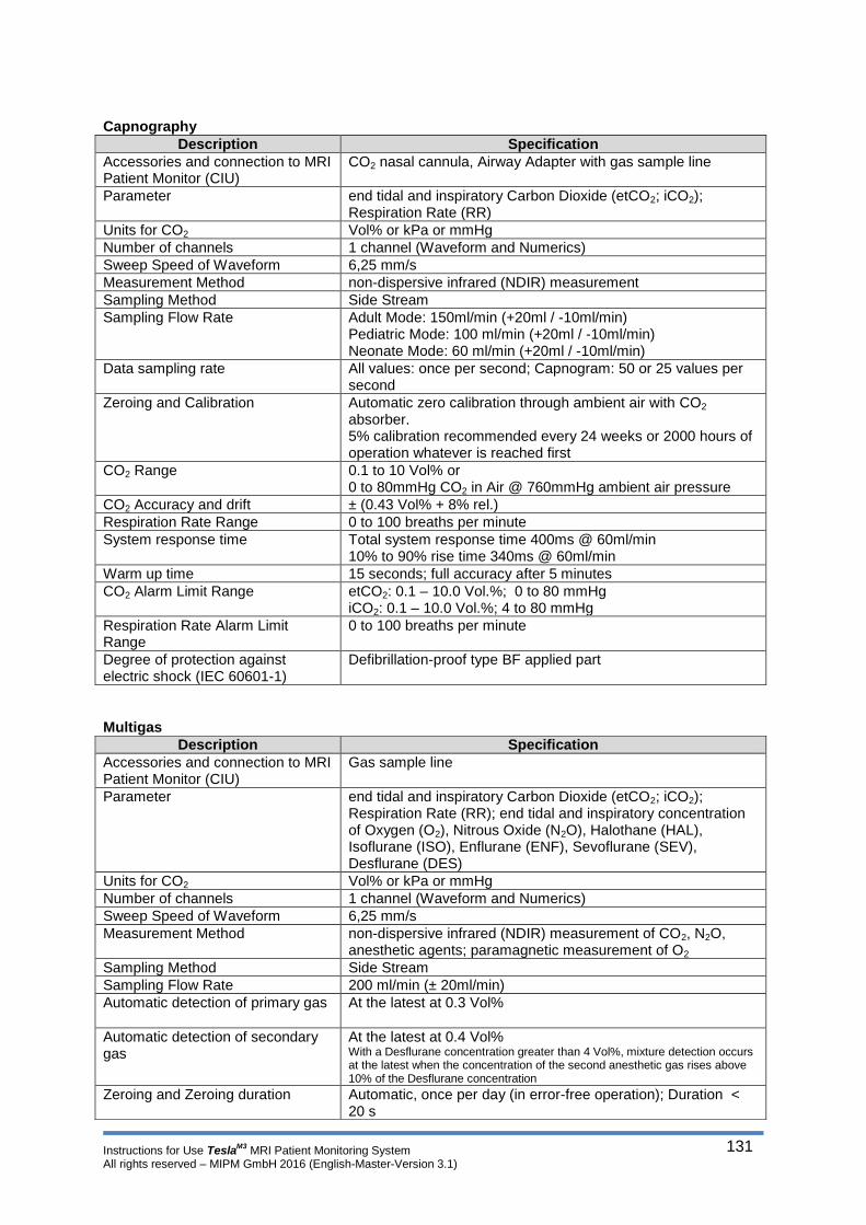
Instructions for Use TeslaM3
MRI Patient Monitoring System All rights reserved – MIPM GmbH 2016 (English-Master-Version 3.1)
131
Capnography
Multigas
Description Specification
Accessories and connection to MRI Patient Monitor (CIU)
CO2 nasal cannula, Airway Adapter with gas sample line
Parameter end tidal and inspiratory Carbon Dioxide (etCO2; iCO2); Respiration Rate (RR)
Units for CO2 Vol% or kPa or mmHg
Number of channels 1 channel (Waveform and Numerics)
Sweep Speed of Waveform 6,25 mm/s
Measurement Method non-dispersive infrared (NDIR) measurement
Sampling Method Side Stream
Sampling Flow Rate Adult Mode: 150ml/min (+20ml / -10ml/min) Pediatric Mode: 100 ml/min (+20ml / -10ml/min) Neonate Mode: 60 ml/min (+20ml / -10ml/min)
Data sampling rate All values: once per second; Capnogram: 50 or 25 values per second
Zeroing and Calibration Automatic zero calibration through ambient air with CO2
absorber. 5% calibration recommended every 24 weeks or 2000 hours of operation whatever is reached first
CO2 Range 0.1 to 10 Vol% or 0 to 80mmHg CO2 in Air @ 760mmHg ambient air pressure
CO2 Accuracy and drift ± (0.43 Vol% + 8% rel.)
Respiration Rate Range 0 to 100 breaths per minute
System response time Total system response time 400ms @ 60ml/min 10% to 90% rise time 340ms @ 60ml/min
Warm up time 15 seconds; full accuracy after 5 minutes
CO2 Alarm Limit Range etCO2: 0.1 – 10.0 Vol.%; 0 to 80 mmHg iCO2: 0.1 – 10.0 Vol.%; 4 to 80 mmHg
Respiration Rate Alarm Limit Range
0 to 100 breaths per minute
Degree of protection against electric shock (IEC 60601-1)
Defibrillation-proof type BF applied part
Description Specification
Accessories and connection to MRI Patient Monitor (CIU)
Gas sample line
Parameter end tidal and inspiratory Carbon Dioxide (etCO2; iCO2); Respiration Rate (RR); end tidal and inspiratory concentration of Oxygen (O2), Nitrous Oxide (N2O), Halothane (HAL), Isoflurane (ISO), Enflurane (ENF), Sevoflurane (SEV), Desflurane (DES)
Units for CO2 Vol% or kPa or mmHg
Number of channels 1 channel (Waveform and Numerics)
Sweep Speed of Waveform 6,25 mm/s
Measurement Method non-dispersive infrared (NDIR) measurement of CO2, N2O, anesthetic agents; paramagnetic measurement of O2
Sampling Method Side Stream
Sampling Flow Rate 200 ml/min (± 20ml/min)
Automatic detection of primary gas At the latest at 0.3 Vol%
Automatic detection of secondary gas
At the latest at 0.4 Vol% With a Desflurane concentration greater than 4 Vol%, mixture detection occurs at the latest when the concentration of the second anesthetic gas rises above 10% of the Desflurane concentration
Zeroing and Zeroing duration Automatic, once per day (in error-free operation); Duration < 20 s

Instructions for Use TeslaM3
MRI Patient Monitoring System All rights reserved – MIPM GmbH 2016 (English-Master-Version 3.1)
132
1)
Duration from power on at 10 °C module temperature to transmission of measurements with unspecified accuracy 2)
Duration from power on at 10 °C module temperature to transmission of measurements with specified accuracy
Description Specification
CO2 Range 0.1 to 10 Vol% or 0 to 80mmHg CO2 in Air @ 760mmHg ambient air pressure
CO2 Accuracy and drift ± (0.43 Vol% + 8% rel.)
CO2 Rise time 10…90%) < 350 ms
CO2 time to availability 1)
< 60 s
CO2 Warm-up time 2)
time to specified accuracy < 300s
N2O Range 0 to 100 Vol%
N2O Accuracy and drift ± (2 Vol% + 8% rel.)
N2O Rise time (10…90%) < 350 ms
N2O Warm-up time 2)
time to specified accuracy < 300s
O2 Range 5 to 100 Vol%
O2 Accuracy and drift ± 2,5 Vol% + 2,5% rel.
O2 Rise time (10…90%) < 500 ms
O2 Warm-up time 2)
time to specified accuracy < 300s
Halothane Range 0 to 8,5 Vol%
Halothane Accuracy and drift ± (0.2 Vol% + 15% rel.)
Isoflurane Range 0 to 8,5 Vol%
Isoflurane Accuracy and drift ± (0.2 Vol% + 15% rel.)
Enflurane Range 0 to 10 Vol%
Enflurane Accuracy and drift ± (0.2 Vol% + 15% rel.)
Sevoflurane Range 0 to 10 Vol%
Sevoflurane Accuracy and drift ± (0.2 Vol% + 15% rel.)
Desflurane Range 0 to 20 Vol %
Desflurane Accuracy and drift ± (0.2 Vol% + 15% rel.)
Agents Rise time (10…90%) < 450 ms
Agents Warm-up time 2)
time to specified accuracy < 300s
Respiration Rate Range 0 to 100 breaths per minute
Respiration Rate Accuracy 0 to 60 breaths per minute ± 1 /min (> 60 breaths per minute not specified)
Total Response time < 1s (CO2); < 30s (O2 and N2O); < 5s (Agents); (incl. watertrap and gas sample line)
Data sampling rate 10 values per second
CO2 Alarm Limit Range etCO2: 0.1 to 10.0 Vol.%; 0 to 80 mmHg iCO2: 0.1 to 10.0 Vol.%; 4 to 80 mmHg
O2 Alarm Limit Range iO2: 18 to 100% etO2: 10 to 100%
Agents Alarm Limit Range Sevoflurane: 0 to10% Isoflurane: 0 to 8.5% Desflurane: 0 to 20% Halothane: 0 to 8.5% Enflurane: 0 to10%
Degree of protection against electric shock (IEC 60601-1)
Defibrillation-proof type BF applied part

Instructions for Use TeslaM3
MRI Patient Monitoring System All rights reserved – MIPM GmbH 2016 (English-Master-Version 3.1)
133
Temperature
Gating
Trends
Events
Interfaces for Data Output of Trend/Event (The MRI Patient Monitor has to be removed from MR Environment before performing a Data Output)
Description Specification
Accessories and connection to MRI Patient Monitor (CIU)
Fiber optic sensor (core or surface)
Parameter Body Temperature
Measurement Method Spectrophotometric fiber optic (direct mode clinical thermometer)
Transient Response Time <15s
Number of channels 1 or 2 channels (Numerics)
Unit °C
Range 20 to 45 °C
Accuracy ± 0.3 °C
Alarm Limit Range 20 to 45 °C
Degree of protection against electric shock (IEC 60601-1)
Defibrillation-proof type BF applied part
Description Specification
ECG gating Maximum of R-Wave (Signal/Pulse according specification for MR Scanner from Siemens)
Pulse Oximetry gating Maximum of Pulse-Wave (Signal/Pulse according specification for MR Scanner from Siemens)
Description Specification
Graphical and Tabular Trends All monitored parameters
Visible Area Visible area (interval length) has to be selected by the user
Interval length 1; 2; 3; 4; 5; 6; 7; 8h
Capacity 8 hours
Description Specification
Tabular Events Date; Time; Patient Name; Event Name and Value (type of event)
Capacity 100 Events (FIFO: First In - First Out)
Event Management An event is automatically created on parameter alarms
Description Specification
Interfaces 2x USB
USB Interface for Trend USB for pen drive or recorder/printer (selectable for the User by GUI)
USB Output format of Trend Selectable: Screenshot or table in ASCII Code (.csv)
USB Interface for Event USB for recorder/printer
USB Output format of Events Screenshot
USB pen drive USB 2.0 / FAT 32 (recommended: Transcend 4 GB)
USB recorder/printer USB 2.0 (recommended: Brother HL 20)
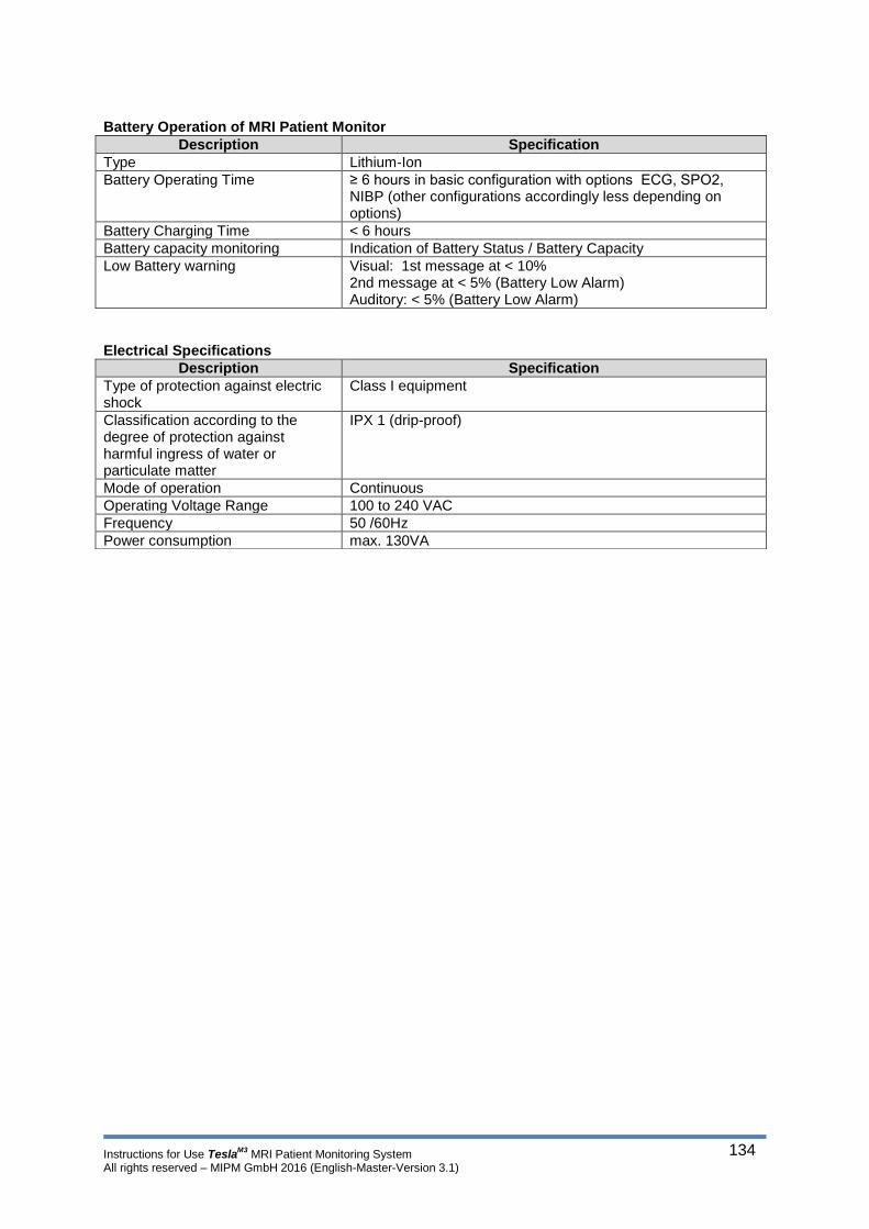
Instructions for Use TeslaM3
MRI Patient Monitoring System All rights reserved – MIPM GmbH 2016 (English-Master-Version 3.1)
134
Battery Operation of MRI Patient Monitor
Electrical Specifications
Description Specification
Type Lithium-Ion
Battery Operating Time ≥ 6 hours in basic configuration with options ECG, SPO2, NIBP (other configurations accordingly less depending on options)
Battery Charging Time < 6 hours
Battery capacity monitoring Indication of Battery Status / Battery Capacity
Low Battery warning Visual: 1st message at < 10% 2nd message at < 5% (Battery Low Alarm) Auditory: < 5% (Battery Low Alarm)
Description Specification
Type of protection against electric shock
Class I equipment
Classification according to the degree of protection against harmful ingress of water or particulate matter
IPX 1 (drip-proof)
Mode of operation Continuous
Operating Voltage Range 100 to 240 VAC
Frequency 50 /60Hz
Power consumption max. 130VA
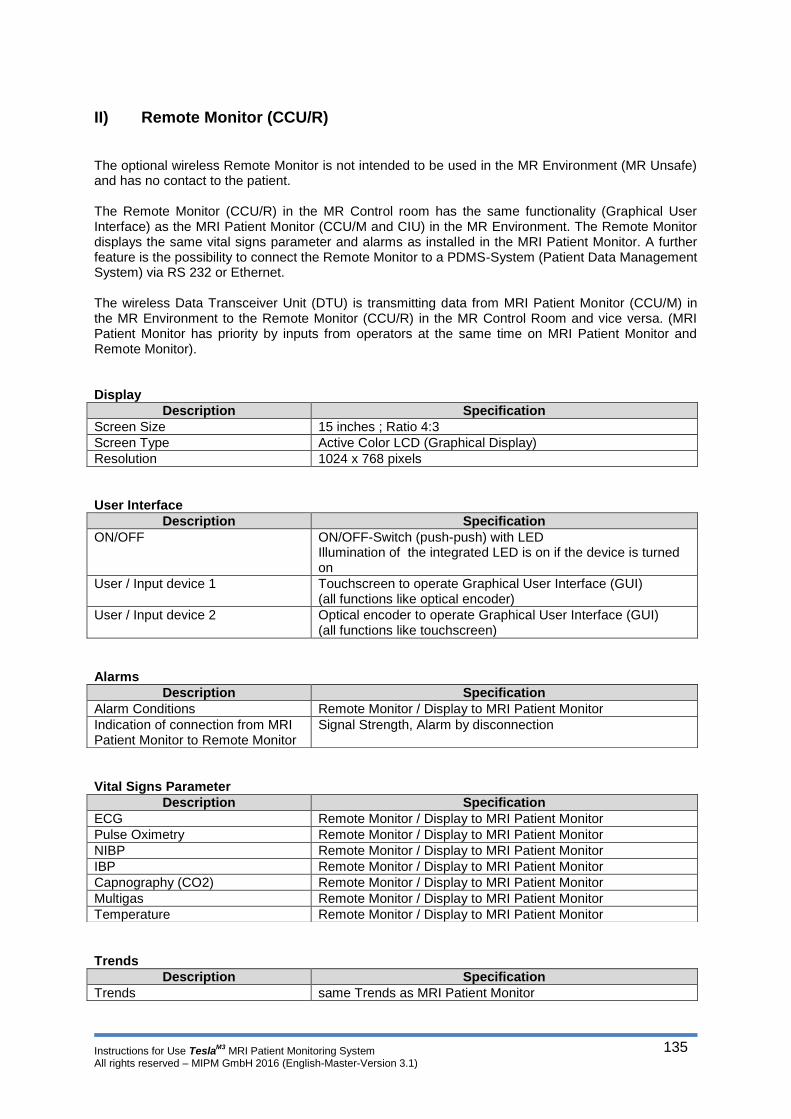
Instructions for Use TeslaM3
MRI Patient Monitoring System All rights reserved – MIPM GmbH 2016 (English-Master-Version 3.1)
135
II) Remote Monitor (CCU/R)
The optional wireless Remote Monitor is not intended to be used in the MR Environment (MR Unsafe) and has no contact to the patient. The Remote Monitor (CCU/R) in the MR Control room has the same functionality (Graphical User Interface) as the MRI Patient Monitor (CCU/M and CIU) in the MR Environment. The Remote Monitor displays the same vital signs parameter and alarms as installed in the MRI Patient Monitor. A further feature is the possibility to connect the Remote Monitor to a PDMS-System (Patient Data Management System) via RS 232 or Ethernet. The wireless Data Transceiver Unit (DTU) is transmitting data from MRI Patient Monitor (CCU/M) in the MR Environment to the Remote Monitor (CCU/R) in the MR Control Room and vice versa. (MRI Patient Monitor has priority by inputs from operators at the same time on MRI Patient Monitor and Remote Monitor). Display
Description Specification
Screen Size 15 inches ; Ratio 4:3
Screen Type Active Color LCD (Graphical Display)
Resolution 1024 x 768 pixels
User Interface
Description Specification
ON/OFF ON/OFF-Switch (push-push) with LED Illumination of the integrated LED is on if the device is turned on
User / Input device 1 Touchscreen to operate Graphical User Interface (GUI) (all functions like optical encoder)
User / Input device 2 Optical encoder to operate Graphical User Interface (GUI) (all functions like touchscreen)
Alarms
Vital Signs Parameter
Trends
Description Specification
Alarm Conditions Remote Monitor / Display to MRI Patient Monitor
Indication of connection from MRI Patient Monitor to Remote Monitor
Signal Strength, Alarm by disconnection
Description Specification
ECG Remote Monitor / Display to MRI Patient Monitor
Pulse Oximetry Remote Monitor / Display to MRI Patient Monitor
NIBP Remote Monitor / Display to MRI Patient Monitor
IBP Remote Monitor / Display to MRI Patient Monitor
Capnography (CO2) Remote Monitor / Display to MRI Patient Monitor
Multigas Remote Monitor / Display to MRI Patient Monitor
Temperature Remote Monitor / Display to MRI Patient Monitor
Description Specification
Trends same Trends as MRI Patient Monitor

Instructions for Use TeslaM3
MRI Patient Monitoring System All rights reserved – MIPM GmbH 2016 (English-Master-Version 3.1)
136
Events
Interfaces for Data Output of Trend/Event
PDMS
Electrical Specifications
Description Specification
Events same Events as MRI Patient Monitor
Description Specification
Interfaces 2x USB (same as MRI Patient Monitor)
Description Specification
Interfaces RS232 or Ethernet ( Selectable over service menu)
Output interval Every 10 seconds
String format RS232 ASCII Code (.csv)
Output format Ethernet ASCII Code (.xml)
Description Specification
Type of protection against electric shock
Class I equipment
Classification according to the degree of protection against harmful ingress of water or particulate matter
IPX 1 (drip-proof)
Mode of operation Continuous
Operating Voltage Range 100 to 240 VAC
Frequency 50 /60Hz
Power consumption max. 55VA
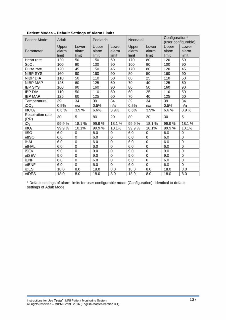
Instructions for Use TeslaM3
MRI Patient Monitoring System All rights reserved – MIPM GmbH 2016 (English-Master-Version 3.1)
137
Patient Modes – Default Settings of Alarm Limits
Patient Mode: Adult Pediatric Neonatal Configuration* (user configurable)
Parameter Upper alarm limit
Lower alarm limit
Upper alarm limit
Lower alarm limit
Upper alarm limit
Lower alarm limit
Upper alarm limit
Lower alarm limit
Heart rate 120 50 150 50 170 80 120 50
SpO2 100 90 100 90 100 90 100 90
Pulse rate 120 45 150 45 170 80 120 45
NIBP SYS 160 90 160 90 80 50 160 90
NIBP DIA 110 50 110 50 60 25 110 50
NIBP MAP 125 60 125 60 70 40 125 60
IBP SYS 160 90 160 90 80 50 160 90
IBP DIA 110 50 110 50 60 25 110 50
IBP MAP 125 60 125 60 70 40 125 60
Temperature 39 34 39 34 39 34 39 34
iCO2 0.5% n/a 0.5% n/a 0.5% n/a 0.5% n/a
etCO2 6.6 % 3.9 % 6.6% 3.9% 6.6% 3.9% 6.6 % 3.9 %
Respiration rate (RR)
30 5 80 20 80 20 30 5
iO2 99.9 % 18.1 % 99.9 % 18.1 % 99.9 % 18.1 % 99.9 % 18.1 %
etO2 99.9 % 10.1% 99.9 % 10.1% 99.9 % 10.1% 99.9 % 10.1%
iISO 6.0 0 6.0 0 6.0 0 6.0 0
etISO 6.0 0 6.0 0 6.0 0 6.0 0
iHAL 6.0 0 6.0 0 6.0 0 6.0 0
etHAL 6.0 0 6.0 0 6.0 0 6.0 0
iSEV 9.0 0 9.0 0 9.0 0 9.0 0
etSEV 9.0 0 9.0 0 9.0 0 9.0 0
iENF 6.0 0 6.0 0 6.0 0 6.0 0
etENF 6.0 0 6.0 0 6.0 0 6.0 0
iDES 18.0 8.0 18.0 8.0 18.0 8.0 18.0 8.0
etDES 18.0 8.0 18.0 8.0 18.0 8.0 18.0 8.0
* Default settings of alarm limits for user configurable mode (Configuration): Identical to default settings of Adult Mode
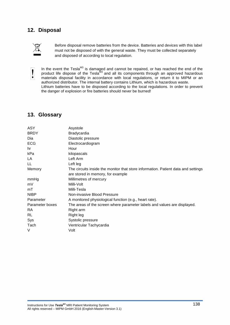
Instructions for Use TeslaM3
MRI Patient Monitoring System All rights reserved – MIPM GmbH 2016 (English-Master-Version 3.1)
138
12. Disposal
Before disposal remove batteries from the device. Batteries and devices with this label
must not be disposed of with the general waste. They must be collected separately
and disposed of according to local regulation.
In the event the Tesla
M3 is damaged and cannot be repaired, or has reached the end of the
product life dispose of the TeslaM3
and all its components through an approved hazardous
materials disposal facility in accordance with local regulations, or return it to MIPM or an authorized distributor. The internal battery contains Lithium, which is hazardous waste. Lithium batteries have to be disposed according to the local regulations. In order to prevent the danger of explosion or fire batteries should never be burned!
13. Glossary
ASY Asystole
BRDY Bradycardia
Dia Diastolic pressure
ECG Electrocardiogram
hr Hour
kPa kilopascals
LA Left Arm
LL Left leg
Memory The circuits inside the monitor that store information. Patient data and settings
are stored in memory, for example
mmHg Millimetres of mercury
mV Milli-Volt
mT Milli-Tesla
NIBP Non-invasive Blood Pressure
Parameter A monitored physiological function (e.g., heart rate).
Parameter boxes The areas of the screen where parameter labels and values are displayed.
RA Right arm
RL Right leg
Sys Systolic pressure
Tach Ventricular Tachycardia
V Volt