test stand design and analysis for titan - nasa · n89- 12609 test stand design and analysis for...
TRANSCRIPT

N89- 12609
TEST STAND DESIGN AND ANALYSIS FORTITAN 34D STATIC FIRING 1
Shayan PazargadiWyle Laboratories
ABSTRACT
The Test Stand iC at the Air Force Astronautics Laboratory
(AFAL), Edwards AFB, CA, was originally designed for F-I liquid
propellant engines. The stand was modified to handle a
5½-segment Solid Rocket Motor (SRM) Titan 34D vertical static
firing test. The new configuration is the only nozzle-down test
stand of long SRM's in the United States, which had to withstand
6.2MN (I.4M pounds) thrust load, and 2444 KN (550 Kips) rocket
weight, as well as seismic and wind loads. The 3230 cm (106
feet) high stand was made of stainless steel truss system
supported by a massive reinforced concrete foundation. The
vertical and lateral thrust loads were mainly resisted by a
four-legged pylon structure attached to the test stand and
foundation. A superstructure was designed to house the rocket
and provide working platforms for stacking operations. Several
finite element models of the combined test stand-pylon-rocket
were developed on ANSYS, NASTRAN and IMAGES-3D softwares. The
models were analyzed for a variety of static, dynamic and
transient loads to ensure the structural integrity of the test
stand. This paper discusses the main design drivers and
analysis effort utilized in the modification of the test stand.
INTRODUCTION
The Test Stand IC located at the Air Force Astronautics
Laboratory (AFAL) at Edwards Air Force Base (EAFB) was one of
the three nearby identical stands which were
(1)Prepared under contract to the United Technologies
Corporation, Chemical Systems Division, UTC-CSD Contract Number
268024.
336
https://ntrs.nasa.gov/search.jsp?R=19890003238 2018-07-18T19:32:25+00:00Z
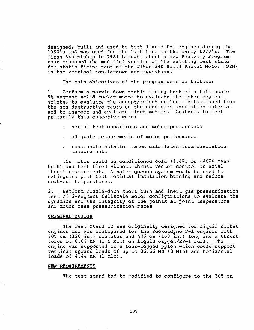
designed, built and used to test liquid F-I engines during the
1960's and was used for the last time in the early 1970's. The
Titan 34D mishap in 1984 brought about a new Recovery Program
that proposed the modified version of the existing test stand
for static firing test of the Titan 34D Solid Rocket Motor (SRM)
in the vertical nozzle-down configuration.
The main objectives of the program were as follows:
i. Perform a nozzle-down static firing test of a full scale
5½-segment solid rocket motor to evaluate the motor segment
joints, to evaluate the accept/reject criteria established fromthe non-destructive tests on the candidate insulation material
and to inspect and evaluate fleet motors. Criteria to meet
primarily this objective were:
o normal test conditions and motor performance
o adequate measurements of motor performance
o reasonable ablation rates calculated from insulation
measurements
The motor would be conditioned cold (4.4oc or +40°F mean
bulk) and test fired without thrust vector control or axial
thrust measurement. A water quench system would be used to
extinguish post test residual insulation burning and reduce
soak-out temperatures.
2. Perform nozzle-down short burn and inert gas pressurization
test of 2-segment fullscale motor configurations to evaluate the
dynamics and the integrity of the joints at joint temperature
and motor case pressurization rates
ORIGINAL DESIGN
The Test Stand IC was originally designed for liquid rocket
engines and was configured for the Rocketdyne F-I engines with
305 cm (120 in.) diameter and 406 cm (160 in.) long and a thrust
force of 6.67 MN (1.5 Mlb) on liquid oxygen/RP-i fuel. The
engine was supported on a four-legged pylon which could support
vertical upward loads of up to 35.56 MN (8 Mlb) and horizontal
loads of 4.44 MN (i Mlb).
NEW REQUIREMENTS
The test stand had to modified to configure to the 305 cm
337
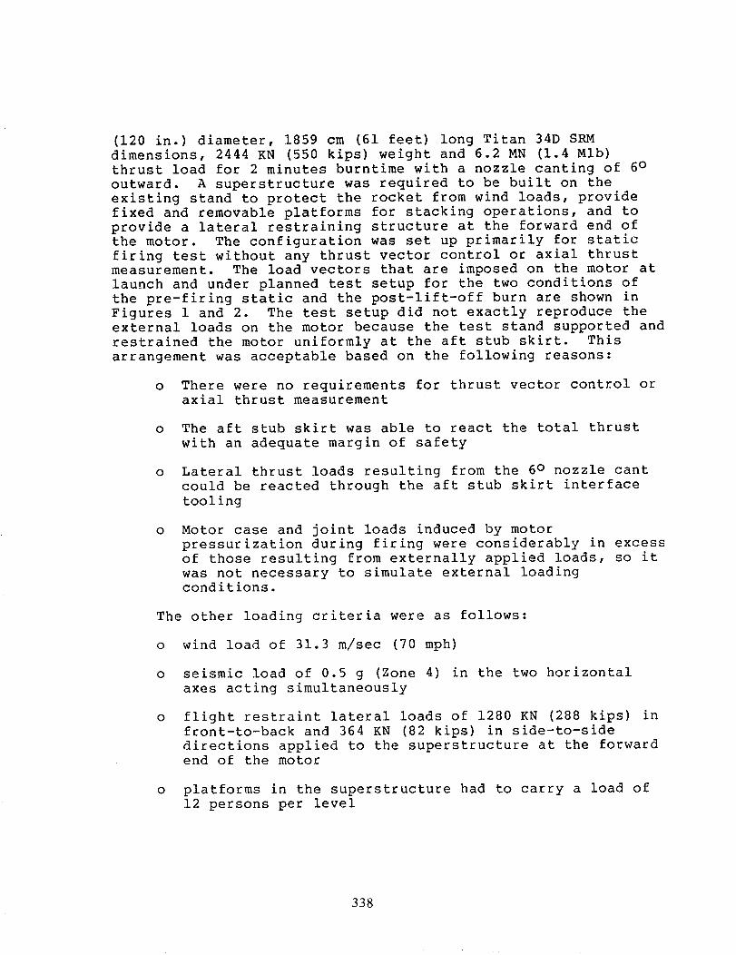
(120 in.) diameter, 1859 cm (61 feet) long Titan 34D SRM
dimensions, 2444 KN (550 kips) weight and 6.2 MN (1.4 Mlb)
thrust load for 2 minutes burntime with a nozzle canting of 6°
outward. A superstructure was required to be built on the
existing stand to protect the rocket from wind loads, provide
fixed and removable platforms for stacking operations, and to
provide a lateral restraining structure at the forward end of
the motor. The configuration was set up primarily for static
firing test without any thrust vector control or axial thrust
measurement. The load vectors that are imposed on the motor at
launch and under planned test setup for the two conditions of
the pre-firing static and the post-lift-off burn are shown in
Figures 1 and 2. The test setup did not exactly reproduce the
external loads on the motor because the test stand supported and
restrained the motor uniformly at the aft stub skirt. This
arrangement was acceptable based on the following reasons:
o There were no requirements for thrust vector control or
axial thrust measurement
o The aft stub skirt was able to react the total thrust
with an adequate margin of safety
o Lateral thrust loads resulting from the 6 ° nozzle cant
could be reacted through the aft stub skirt interface
tooling
o Motor case and joint loads induced by motor
pressurization during firing were considerably in excess
of those resulting from externally applied loads, so it
was not necessary to simulate external loading
conditions.
The other loading criteria were as follows:
o wind load of 31.3 m/sec (70 mph)
o seismic load of 0.5 g (Zone 4) in the two horizontal
axes acting simultaneously
o flight restraint lateral loads of 1280 KN (288 kips) in
front-to-back and 364 KN (82 kips) in side-to-side
directions applied to the superstructure at the forward
end of the motor
o platforms in the superstructure had to carry a load of
12 persons per level
338

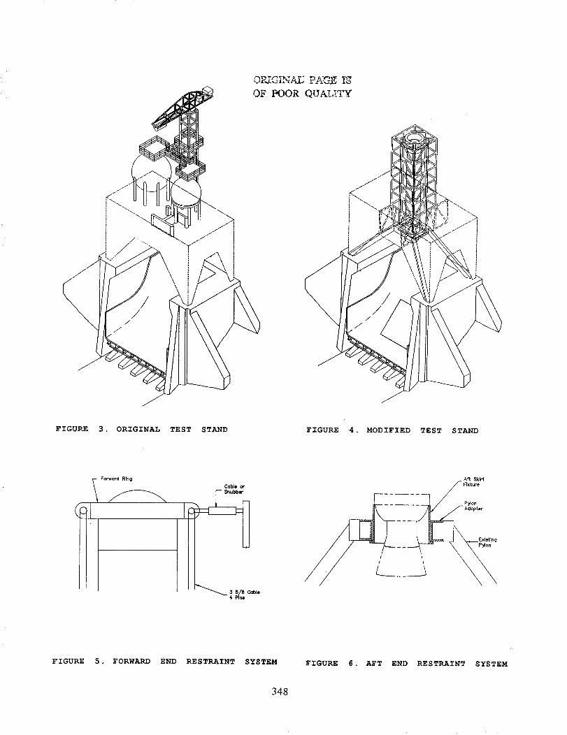
NEW DESIGN
The following modifications were made to the original stand
(Fig.3) to adapt to the new requirements of Titan 34D static
firing tests on the modified stand (Fig.4):
o removal of the following
five tone jib crane and liquid oxygen tanks from the top
platforms above the tanks
Two 36 WF beams from the top of the existing stand
plumbing between the tanks
Firex piping
engine mount and thrust measuring H-beam
tank support columns
o Superstructure of K-type A36 steel frame added to the
existing stand. The superstructure was to provide wind
protection to the motor, fixed and removable platform
for stacking operations and lateral restraint at the
forward ring attachment at the 1463 cm (48 feet) level
above the existing stand.
o A forward ring (Fig.5) at the forward end of the motor
that provided axial restraint through the anti-flight
restraint cables and lateral restraint through snubber
connection to the superstructure in both horizontaldirections.
o Pylon adaptor made of A36 steel and aft skirt fixture
made of 4130 steel both designed to 44.4 MN (i0 Mlb)
vertical thrust load to provide interface between the
pylon and the rocket aft end (Fig.6). The pylon adapter
was designed to connect the existing rectangular pylon
opening with the 305 cm (i0 feet) diameter thrust
cylinder. The aft skirt fixture was designed to provide
the interface between the pylon adapter fixture and the
motor aft stub skirt.
o The pylon was attached to the test stand to provide
better dynamic stability of the motor-pylon assembly.
This improvement will be discussed later in the paper in
more detail.
o A working platform was added at 244 cm (8 feet) below
the top of the existing stand to support a 6800 Kg
(15000 ib) x-ray machine. The 5½ segment setup and
configuration of the platforms are shown in Figure 7.
339
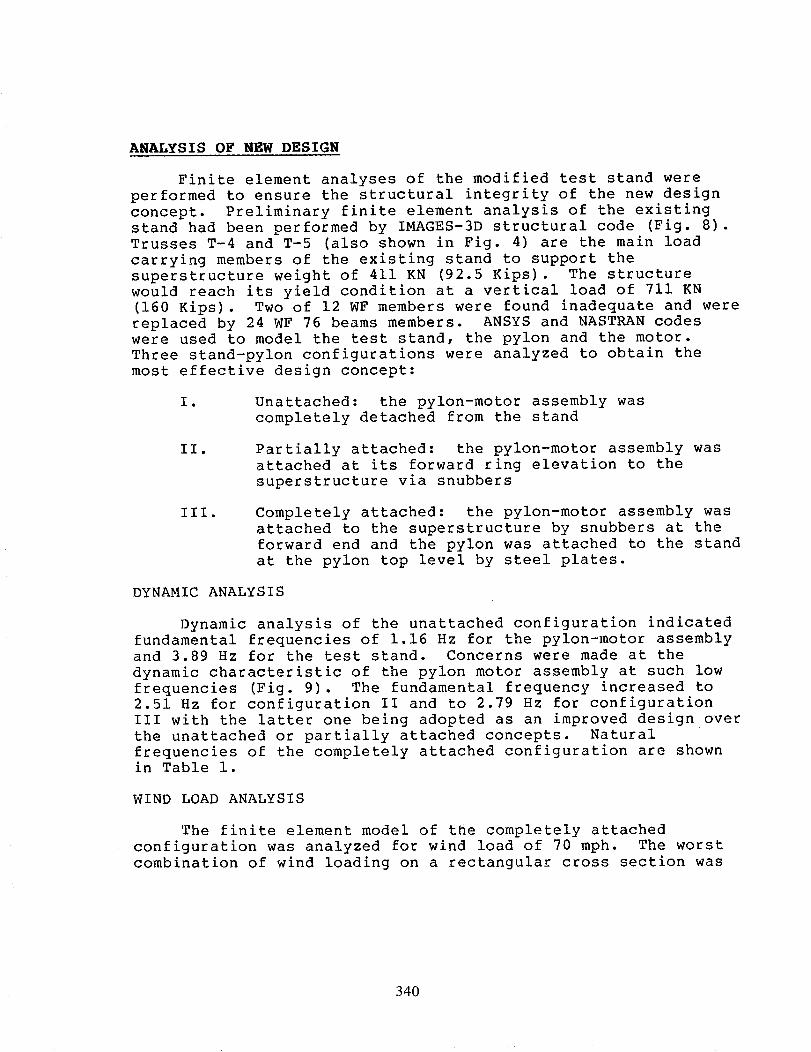
ANALYSIS OF NEW DESIGN
Finite element analyses of the modified test stand were
performed to ensure the structural integrity of the new design
concept• Preliminary finite element analysis of the existing
stand had been performed by IMAGES-3D structural code (Fig. 8).
Trusses T-4 and T-5 (also shown in Fig. 4) are the main load
carrying members of the existing stand to support the
superstructure weight of 411 KN (92.5 Kips). The structure
would reach its yield condition at a vertical load of 711 KN
(160 Kips)• Two of 12 WF members were found inadequate and were
replaced by 24 WF 76 beams members. ANSYS and NASTRAN codes
were used to model the test stand, the pylon and the motor.
Three stand-pylon configurations were analyzed to obtain the
most effective design concept:
I • Unattached: the pylon-motor assembly was
completely detached from the stand
II. Partially attached: the pylon-motor assembly was
attached at its forward ring elevation to the
superstructure via snubbers
III. Completely attached: the pylon-motor assembly was
attached to the superstructure by snubbers at the
forward end and the pylon was attached to the stand
at the pylon top level by steel plates•
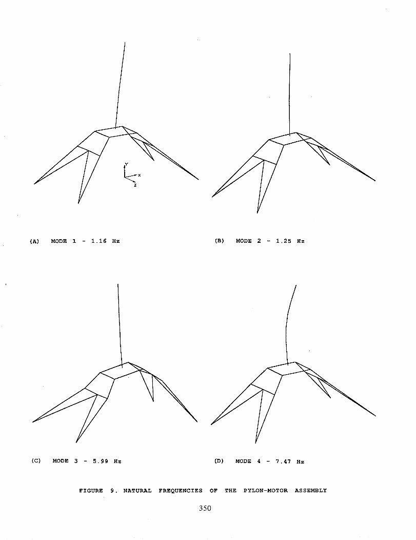
DYNAMIC ANALYSIS
Dynamic analysis of the unattached configuration indicated
fundamental frequencies of 1.16 Hz for the pylon-motor assembly
and 3.89 Hz for the test stand. Concerns were made at the
dynamic characteristic of the pylon motor assembly at such low
frequencies (Fig. 9). The fundamental frequency increased to
2.51 Hz for configuration II and to 2.79 Hz for configuration
III with the latter one being adopted as an improved design over
the unattached or partially attached concepts. Natural
frequencies of the completely attached configuration are shown
in Table i.
WIND LOAD ANALYSIS
The finite element model of the completely attached
configuration was analyzed for wind load of 70 mph. The worst
combination of wind loading on a rectangular cross section was
340
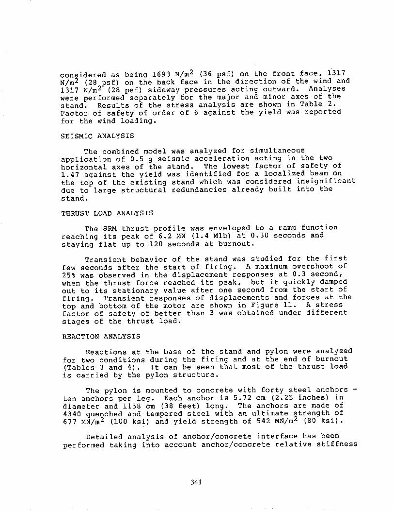
considered as being 1693 N/m 2 (36 psf) on the front face, 1317
N/m 2 (28^psf) on the back face in the direction of the wind and
1317 N/m z (28 psf) sideway pressures acting outward. Analyses
were performed separately for the major and minor axes of thestand. Results of the stress analysis are shown in Table 2.
Factor of safety of order of 6 against the yield was reported
for the wind loading.
SEISMIC ANALYSIS
The combined model was analyzed for simultaneous
application of 0.5 g seismic acceleration acting in the two
horizontal axes of the stand. The lowest factor of safety of
1.47 against the yield was identified for a localized beam on
the top of the existing stand which was considered insignificant
due to large structural redundancies already built into the
stand.
THRUST LOAD ANALYSIS
The SRM thrust profile was enveloped to a ramp function
reaching its peak of 6.2 MN (1.4 Mlb) at 0.30 seconds and
staying flat up to 120 seconds at burnout.
Transient behavior of the stand was studied for the first
few seconds after the start of firing. A maximum overshoot of
25% was observed in the displacement responses at 0.3 second,
when the thrust force reached its peak, but it quickly damped
out to its stationary value after one second from the start of
firing. Transient responses of displacements and forces at the
top and bottom of the motor are shown in Figure ii. A stress
factor of safety of better than 3 was obtained under different
stages of the thrust load.
REACTION ANALYSIS
Reactions at the base of the stand and pylon were analyzed
for two conditions during the firing and at the end of burnout
(Tables 3 and 4). It can be seen that most of the thrust load
is carried by the pylon structure.
The pylon is mounted to concrete with forty steel anchors -
ten anchors per leg. Each anchor is 5.72 cm (2.25 inches) in
diameter and 1158 cm (38 feet) long. The anchors are made of
4340 quenched and tempered steel with an ultimate strength of
677 MN/m 2 (i00 ksi) and yield strength of 542 MN/m 2 (80 ksi).
Detailed analysis of anchor/concrete interface has been
performed taking into account anchor/concrete relative stiffness
341

and specified anchor bolt preload of 889 KN (200 kips). The
results of the analysis limit maximum postulated thrust force to
35.56 MN (8 Mlb) which was consistent with the original design
for liquid F-I engine tests. The maximum required postulated
thrust force of 44.44 MN (i0 Mlb) did not exceed the ultimate
strength of the anchor.
CONCLUSIONS
The main design drivers in the modification of the F-I
liquid propellant engine Test Stand IC to accommodate for theTitan 34D solid rocket booster nozzle-down static firing test
were:
o vertical thrust load and lateral thrust load (caused by
6° nozzle cant) of the SRM are an order of magnitude
larger than liquid engines and they have to be resisted
primarily by the pylon structure.
o due to a much heavier and taller SRM with respect to
liquid engines, resonance frequencies of the motor-pylon
assembly will become a critical factor in the stability
of the assembly under dynamic environments such as
earthquake, wind and transient thrust loads. For this
reason, the motor-pylon assembly had to be tied-in to
the test stand at the pylon level and the motor forward
end had to be attached to the superstructure. This
tied-in configuration increased the fundamental
frequency of the assembly by a factor of 2.4.
o no thrust vector control or axial thrust measurement was
required for this Titan 34D static firing test. The
anti-flight forward end restraint cables and snubbers
and the uniform restraint pylon system at the aft end
considered to be acceptable in lieu of the actual
restraint system of the SRM to the core vehicle.
342

TABLE i. - GLOBAL NATURAL FREQUENCIES (Hz)
UNATTACHED PYLON-STAND (CASE I)
Pylon
Stand
PARTIALLY ATTACHED (CASE II)
COMPLETELY ATTACHED (CASE III)
ANSYS
MODE
_ASTRAN
1.16 1.18 ix(*)
1.25 1.31 Iz
3.89 4.29 Iz
5.42 6.38 Ix
2.51 2.74 Iz
2.70 2.98 ix
5.12 5.26 Combined
7.11 7.35 2z
7.31 7.49 2x
2.79 3.0 ix
2.84 3.0 iz
7.09 7.36 2z
7.44 7.69 2x
(*) x, y, z correspond to side-to-side, vertical and road-to-flame
directions respectively.
343

TABLE 2. - STRESS AND DISPLACEMENT SUMMARY
Loading/Condition
Maximum Stress
MN/m 2 (ksi)
Factor of Safety
(Against Yield)
Displacement
cm (inches)
Dead Load (DL)
Front wind and DL
Side wind and DL
Seismic (combined x & z) and DL
Thrust and DL (Case II)
Thrust and DL (Case III)
Thrust (end of burnout) and DL (Case III)
Ultimate load (1) at top and DL
22.35 (3.3) 10.91
39.97 (5.9) 6.10
35.22 (5.2) 6.92
165.96 (24.5) 1.47
29.81 (4.4) 8.18
63 (9.3) 3.87
75.87 (11.2) 3.21
216.77 (32) 1.13
28 .lly) (2)
08 .03z)
05 .02x)
2 29 .9 x and z)
15 .06y)
05 .02y)
28 .lly)
3.38 (1.33z)
_o
(i) 1280 KN (288 kips) in z- and 364 KN (82 kips) in x-directions applied at strut elevation.
(2) x, y, z correspond to side-to-side, vertical and road-to-flame directions respectively.

TABLE 3. - REACTION FORCES OF THE RESTRAINT SYSTEM DURING THE STATIC FIRING TEST
%O
4_
O©
oZ
Item Fx Fy F z Mx My Mz
Stand 44 (I0) 329 (74) -49 (-ii) -497 (-44) 226 (20) 858
Base Reactions 44 (-i0) 329 (74) -53 (-12) -576 (-51) -226 (-20) -835
62 (14) 271 (61) 4 (i) -2213 (-196) 293 (26) 847
(76)
(-74)
(75)
-62 (-14) 267 (60) 9 (2) -2503 (-20.4) -305 (-27)
Stand Subtotal 0 (0) 1196 (269) -89 (-20) -5589 (-495) -12 (-i)
-926 (-82)
-56 (-5)
Pylon -169 (-38) -124 (-28) 36 (8) 2371 (210) 5159 (457) 13953 (1236)
Base Reactions 169 (38) -124 (-28) 36 (8) 2303 (204) -5159 (-457) -13885 (-1230)
573 (129) -676 (-152) -302 (-68) -10792 (-956) -1897 (-168) -14867 (-1317)
-573 (-129) -676 (-152) -302 (-68) -10770 (-954) 1818 (161) 15082 (1336)
Pylon Subtotal 0 (0) -1600 (-360) -533 (-120) -16888 (-1496) -79 (-7) 283 (25)
TOTAL 0 (0) -404 (-91) -622 (-140) --22476 (-991) -90 (-8) 226 (20)
Notes:
(I) Force units are in KN, Kips in parentheses. Moments units are in KN-cm, Kips-in. in parentheses.\
(2) (+) sign is in direction of positive global coordinates.
(3) Maximum force at top strut is 3316 N (746 ibs) .
(4) Forces at the pylon to the stand connection
are distributed as follows:
(6) Force Checkout in vertical direction:
Fy Fz
To the pylon 2631 (592) 542 (122)
To the stand 1013 (228) 80 (18)
TOTAL 3644 (820) 622 (140)
(5) Rocket weight is 2444 KN (550 Kips).
Fy
Rocket and pylon weight -3604 (-811)
Stand Weight -2213 (-498)
Thrust Load 6222 (+1400)
Reaction at pylon -1600 (-360)
Reaction at stand 1195 (+269)
TOTAL 0 (0)
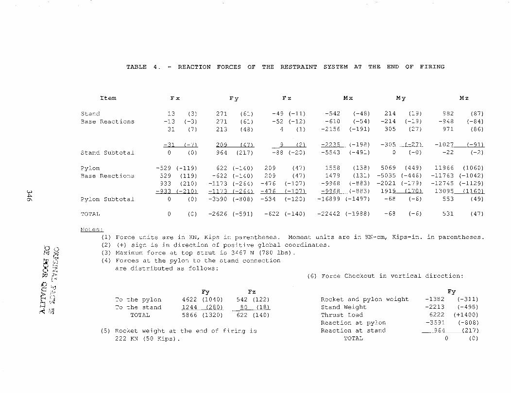
TABLE 4. - REACTION FORCES OF THE RESTRAINT SYSTEM AT THE END OF FIRING
t_
Oh
_O
[4
Item Fx Fy F z Mx My Mz
Stand
Base Reactions
13 (3) 271 (61) -49 (-ii) -542 (-48) 214 (19) 982 (87)
-13 (-3) 271 (61) -52 (-12) -610 (-54) -214 (-19) -948 (-84)
31 (7) 213 (48) 4 (i) -2156 (-191) 305 (27) 971 (86)
Stand Subtotal
-$I (-7) 209 (47) 9 (2) -2235 (-198) -305 (-27) -1027 (-91)
0 (0) 964 (217) -88 (-20) -5543 (-491) 0 (-0) -22 (-2)
Pylon
Base Reactions
Pylon Subtotal
-529 (-119) 622 (-140) 209 (47) 1558 (138) 5069 (449) 11966 (1060)
529 (119) -622 (-140) 209 (47) 1479 (131) -5035 (-446) -11763 (-1042)
933 (210) -1173 (-264) -476 (-107) -9968 (-883) -2021 (-179) -12745 (-1129)
-935 (-210) -1173 (-2641 -476 (-107) -9968 (-883) 1919 (170) 13095 (1160)
0 (0) -3590 (-808) -534 (-120) -16899 (-1497) -68 (-6) 553 (49)
TOTAL 0 (0) -2626 (-591) -622 (-140) -22442 (-1988) -68 (-6) 531 (47)
Notes:
(i) Force units are in KN, Kips in parentheses. Moment units are in KN-cm, Kips-in. in parentheses.
(2) (+) sign is in direction of positive global coordinates.
(3) Maximum force at top strut is 3467 N (780 ibs) .
(4) Forces at the pylon to the stand connection
are distributed as follows:
(6) Force Checkout in vertical direction:
Fy Fz
To the pylon 4622 (1040) 542 (122)
To the stand 1244 (280) 80 (18)
TOTAL 5866 (1320) 622 (140)
(5) Rocket weight at the end of firing is
222 KN (50 Kips).
Fy
Rocket and pylon weight -1382 (-311)
Stand Weight -2213 (-498)
Thrust Load 6222 (+1400)
Reaction at pylon -3591 (-808)
Reaction at stand 964 (217)
TOTAL 0 (0)

W N
l
SII
W.otsTmeux_o
@
i
Fzc ::_Fx._ _:-_l Fzp Fxt"
ACTUAL
DPJGI'NAL PAG.E ]_g
o_ POORQU,_,xT_
<:7" _E> ANTI-FLmHTRESTRAINT
__ FIXTURE
WR l W-_R
2 __,._ 2
Ii
WM '
$-4.--
I
\\\ \\ _\\_,.'9 " "'
._..p.
Fz w
_BASE
THRUST
FIXTURE
TEST SIMULATION
FIGURE I. COMPARISON OF THE LOAD RESTRAINT SYSTEM BETWEEN ACTUAL
AND TEST SIMULATION - PREFIRE
Fx,0_
.T_L :
Fz i 4
_1STRIBUT._______
Fz :
+T
ACTUAL
Fx. O'C_
W__R_.2
i.... _ ANTI-FLIGHT
RESTRAINTFIXTURE
WR2
"I_____:
:4-
FZN _ ._i N
- _.
_ _ FIXTURE
TEST SIMULATION
FIGURE 2. COMPARISON OF THE LOAD RESTRAINT SYSTEM BETWEEN ACTUAL
AND TEST SIMULATION - POST LIFTOFF
347
OP_iGiNAI_ PA'G_ l_J
OF POOR QUALITY
I/
FIGURE 3. ORIGINAL TEST STAND FIGURE 4. MODIFIED TEST STAND
Forward Rtng
Cable or
'__ 3 5/8 Cable
4 P1¢8
Aft Skirt
/i
FIGURE 5. FORWARD END RESTRAINT SYSTEM FIGURE 6. AFT END RESTRAINT SYSTEM
348

ORIGINAU PAGE I_
OF POOR QUALITY
23'
17' Column joint
_12 ° 1"
8' 7" (2)
2'
FIGURE 7 . 5-I/2 MOTOR SEGMENT SETUP
FIGURE 8 . FINITE ELEMENT MODEL OF THE EXISTING STAND
349
(A) MODE 1 - 1.16 Hz (B) MODE 2 - 1.25 Hz
/
(C) MODE 3 - 5.99 Hz (D) MODE 4 - 7.47 Hz
FIGURE 9. NATURAL FREQUENCIES OF THE PYLON-MOTOR ASSEMBLY
350

Y
Z
¥
Z
(A) MODE 1 - 2.79 Hz (B) MODE 2 2.84 Hz
(C) MODE 3 - 7.09 Hz (D) MODE 4 - 7.44 Hz
FIGURE i0. NATURAL FREQUENCIES OF THE COMPLETELY ATTACHED
STAND-PYLON-MOTOR ASSEMBLY
351

!!
.#2/
(Fo) . 6216 KN (1400 Kips)
(Fo) z = 621,6 KN (140 Kips)
AI
IIIIIII
II
III
T/ME (SEe)
(A) IDEALIZED THRUST LOAD
ORIGINAL PAGE IS
OF, DOOR QUALIT]
//i
/r/!
/
.m .z_ .n _ .el ._ ,!I L.IO +ax I.zw
Time (seconds)
(B) VERTICAL DISPLACEMENT AT THE BASE OF THE MOTOR
/
!/
i.tz .z. .u .w ._ .m ._ I.w )_z i.w
Time (seconds)
(C) VERTICAL DISPLACEMENT AT THE TOP OF THE MOTOR
-O_ --
,_E / \
.tz .z_ .I-r .io .ez .lw ._ t.m 3,+=
Time (seconds)
\\/\/
A
\/
(D) LATERAL DISPLACEMENT (Z) AT THE TOP OF THE MOTOR
,..i_, l / l/
:753q'L_-) .tz .Z= ._' .W ._ ._ .wr t.u. i.= L.Z= _
Time (seconds)
(E) LATERAL FORCE (X) IN THE FORWARD END UNISTRUT
;2_/';°3
7 " 'tk / '/ / d
Time (seconds)
(F) LATERAL FORCE (Z) IN THE FORWARD END UNISTRUT
FIGURE Ii. TIME HISTORY RESULTS DUE TO THRUST LOADS
352