testbed for mitigation of power fluctuation on micro-gridelectriconf/slides_2015/zhao... · ·...
TRANSCRIPT

Testbed for Mitigation of Power Fluctuation on Micro-Grid
Presented by Xin Zhao
UC San DiegoApril 1, 2015
10th Carnegie Mellon Conference onThe Electricity Industry
Acknowledgements
• Xin Zhao System Identification and Control Laboratory, UC San Diego
• Raymond de Callafon System Identification and Control Laboratory, UC San Diego
• Maurice van de Ven Eindhoven University of Technology
• William Torre Center for Energy Research, UC San Diego
• Chuck Wells Center for Excellence, OSIsoft
UC San Diego Team
• Greg Smedley One-Cycle Control Inc.
• Tong Chen One-Cycle Control Inc.
OCC Team
2 of 20
The project was sponsored by the California Energy Commission.

Outline
• Introduction
• Testbed for mitigation of power fluctuation– Overview– “Portable” cabinet– Controller
• Future work
• Preliminary tests on the testbed
3 of 20

Introduction

Introduction
Motivation for mitigation of power fluctuation
• Power fluctuation occurs intermittently on micro-grid.
• Conventional generation tends to stabilize and maintain synchronous operation of the system by the inertia in the form of spinning rotational mass.
• As more renewable energy generation is added to the utility grid, it could result in instability and poorly damped oscillations in AC frequency and power on micro-grid.
5 of 20

Introduction
Objectives of building a testbed
• Simulate a power fluctuation– Motor load– Oscillatory circuitry
• Detection of instantaneous fluctuations– Phasor Measurement Unit (PMU)– Instantaneous power sensor
• Verification of data-based dynamic modeling (system identification) techniques
• Damping controller design and implementation– Embedded devices
• Capability of real-time control of an inverter– An inverter with real-time active/reactive power control
6 of 20

Testbed

Testbed – Overview
PVSystem
Grid-TiedInverter
EMIFilter
L1
L2
L3
A
Controller
A
V
AuxiliaryRelay
OverloadProtectionContactor
CircuitBreaker
GRID
Sensors
Switch
A
V
V
R-L-C Load Circuit
System diagram
Inverter with real-time control
Oscillatory circuitry acting as a power fluctuation
Controller with implementation of instantaneous power calculation and damping control
8 of 20

Testbed – Key Components
“Portable” cabinet
Oscillatory R-L-C circuitry
Grid-Tied Inverter Controller Cabin
9 of 20

Testbed – Key Components
Controller
Manufacturer: National InstrumentsModel: NI myRIO-1900
• Processor: Xilinx Z-7010 (Duo Core, 667MHz)• Memory: (ROM) 256MB (DDR3) 512MB• Wireless: IEEE 802.11 b,g,n• Analog Input: 12 bits – 500 kS/s• Analog Output: 12 bits – 345 kS/s
10 of 20

Preliminary Tests

Preliminary Tests
Test of simulating power fluctuation
• For safety consideration, a programmable DC power supply is installed for testing.
• The power fluctuation generated by the oscillatory circuitry is measured and modeled as follows:
1 1.2 1.4 1.6 1.8 2 2.2 2.4 2.6 2.8 3-40
-20
0
20
40
60
80
100
Time [sec]
3-ph
ase
Rea
l Pow
er
System MeasurementModel Simulation
12 of 20
Preliminary Tests
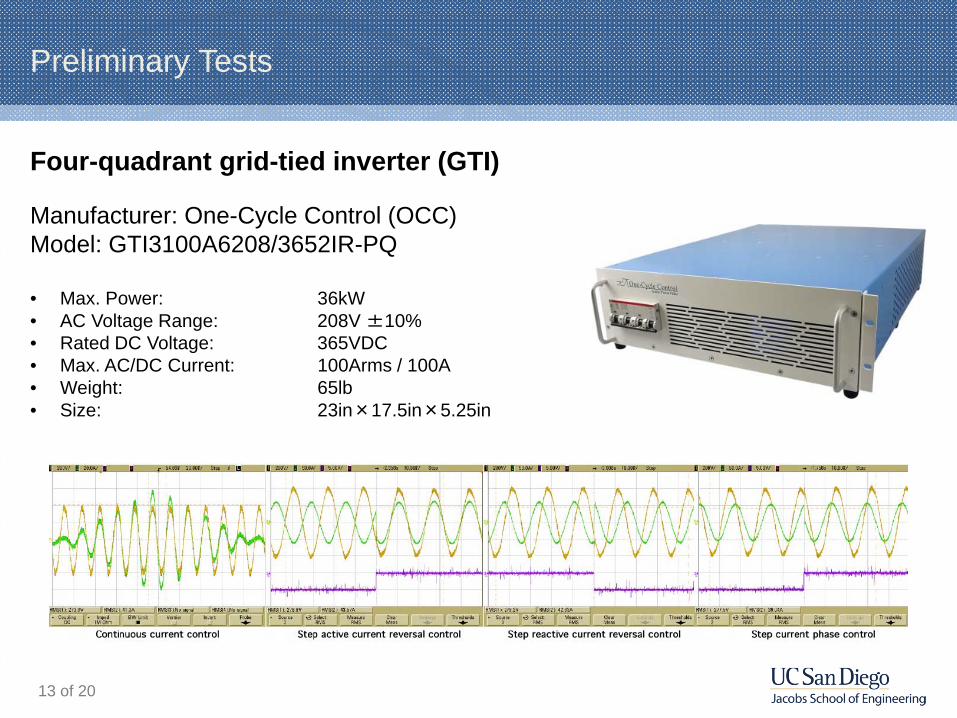
Four-quadrant grid-tied inverter (GTI)
Manufacturer: One-Cycle Control (OCC)Model: GTI3100A6208/3652IR-PQ
• Max. Power: 36kW• AC Voltage Range: 208V ±10%• Rated DC Voltage: 365VDC• Max. AC/DC Current: 100Arms / 100A• Weight: 65lb • Size: 23in×17.5in×5.25in
13 of 20

Preliminary Tests
Capability test of real-time active/reactive power control
• Dynamic response of the OCC-GTI is tested with a step control input.
• The OCC-GTI is capable to be controlled in real time.
14 of 20
4 4.2 4.4 4.6 4.8 5 5.2 5.4 5.6 5.8 6-20
-10
0
10
20
30
40
Rea
l Pow
er
Time (sec)4 4.2 4.4 4.6 4.8 5 5.2 5.4 5.6 5.8 6
0
1
Ste
p In
put t
o G
TI

Preliminary Tests
Verification of data-based system identification on the GTI output
• Based on the measured data obtained by previous tests, a low-order model built within Prediction Error (PE) framework is capable to capture the dynamics.
15 of 20
4 4.2 4.4 4.6 4.8 5 5.2 5.4 5.6 5.8 6-20
-10
0
10
20
30
40
Time [sec]
3-ph
ase
Rea
l Pow
er
Measured ResultSimulated Result

Preliminary Tests
Verification of data-based system identification on the disturbance
• Dynamic response of the oscillatory circuitry is tested.
• A low-order model built by Step-Based Realization (SBR) method is capable to capture the dynamics well.
16 of 20
0 0.2 0.4 0.6 0.8 1 1.2 1.4 1.6 1.8 2-40
-20
0
20
40
60
80
100
Time [sec]
3-ph
ase
Rea
l Pow
er
Measured ResultSimulated Result

Preliminary Tests
Damping control algorithm design and implementation
• A preliminary damping control algorithm is designed based on modeling of the system described previously.
• The control algorithm is implemented in the controller.
1 1.2 1.4 1.6 1.8 2 2.2 2.4 2.6 2.8 3-40
-20
0
20
40
60
80
100
Time [sec]
3-P
hase
Rea
l Pow
er
Open-Loop SimulationClosed-Loop Simulation
0 0.2 0.4 0.6 0.8 1 1.2 1.4 1.6 1.8 2-80
-60
-40
-20
0
20
40
60
80
100
120
Time [sec]
3-P
hase
Rea
l Pow
er
No ControlWith Feedback Control
Control Algorithm Design Control Algorithm Implementation
17 of 20

Preliminary Tests
Conclusions
• The oscillatory circuitry in the testbed is able to simulate a power fluctuation.
• The grid-tied inverter provided by One-Cycle Control is capable to be controlled in real time.
• The controller is able to process the instantaneous power calculation and real-time control.
• The designed control algorithm is able to dampen the oscillation generated by the oscillatory circuitry.
18 of 20

Future Work

Future Work
Large-scale integration tests
• Integration with Phasor Measurement Unit (PMU)
• Integration with photovoltaic (PV) systems
• Large-scale tests on UCSD micro-grid
20 of 20

Thank you