t.,ffd'-- fir
TRANSCRIPT

D City box number t.,ffd'-- - fir<-~ · D ~cover page withe following info:
1 ~ Company (author) name
~eportDate
~roject name D Company's job number
_.Q--City DCLU project number (7-digit number)
J;Ycity Permit number (6-digit number)
~Kroll map index number (3-digit number, w?/E,W,N,S)
,Ja'Greenlabel •
4 Site address (may be on 151 or 2°d page of text)
D ecutive Summary an.ct associated figures
Table of Contents
D Project Location Plan/Map or Vicinity Map
Site Plans, Boring Location Plans, or Exploration Plans
. D Survey
D Geologic Maps X . -
D Fill or Peat Thickness Maps and Contour Maps
Boring Logs
D Geology Text (if no logs)
D Soil Classification Key/Boring Log Key
D Probe Logs
D Test Pit Logs
D Monitoring Well Logs
D Cone Penetrometer Logs
D Shear Wave Velocity Measurements
D Groundwater Maps
D GW Elevation Tables/Data
D Soils Lab Testing (Geotechnical) Summary Tables
?-Gr~ses/Hydrometer Analyses
D Atterberg Limits
D Strength tests: Triaxial, Unconfined, Direct Shear
D Organic Content
D 14C or Radiocarbon Testing D Other _____________ _
D Soil Chemical Analytical Testing Summary Tables
0 Water/Groundwater Chemical Analytical Summary Tables 0 Comments _______________ _
0 Date Copied f ~ J{ -C(j By M
2/9/99

. _., ,,-..~
!J'-.:".;;C"'·J :.">COW... c:= -c:C-..:-:: .._.. r-...
0 0-. 0 i'. (!; •• c,-.-;=
-cc ~ z C-·J
c, ?"- r-... u a-,.
< ... wr..o
:-: ~>-
::CL:J!-0 ::...) W::H U:: <:: 3D... ~>- 0...
--= Lw -1 CJ .::C
cc Lt..-J.::C C: ::.:::i WO::
I ~~zL:.13:~ ' :-:_JC;
}- -1::.::: ¢.::!
-i:::UJ....JZ:-..z ilJH_J(:'; '-. ::=: 3 (i; H L:J Ci..,H~ ::CH H (_l;,r:C 0:: _J !~ >- 4: Li.. L:J -1Z-1 Z HHHWwJC.) IC:::E:G1ZO 0... _J <=::::a:
HU,. ::: ::c l- ?- er.: !:l:!w.Jf.fJWWZ
z:--::=::J.-::c 0-. O......i;;:r:O:::_.l M ~!-l-W-1.:1 a,("~ tr.: ::.r:: t·J. ::C!-ZZW:: co wmc:ow ,-; ~L:.Juuw_
0 U j::: o ~wzoo
February 5, 1997
Phil and Natalie Morrell 10022 51stAve. SW Seattle, WA. 98146
Re: Plan Review for 10022 51st Avenue SW
Dear Phil and Natalie:
Mark T. Otten, P .E . Engineering Consultant
3029 NE 182nd Street Seattle, WA. 98155
(206) 365-9266 Fax (206) 365-9973
I have reviewed the foundation, earthwork, retaining wall, and sitework portions of the plans and specifications for your new residence at 10022 51st Avenue SW. The plans and specifications are in conformance with my Geotechnical Engineering Report dated December 6, 1996.
In view of the recent landslide activity in the Puget Sound Region, I reviewed the slope stability aspects in detail. As described in the Geotechnical Report, the existing slope on your property is 20 to 25 percent. I have observed several landslides in recent weeks, but they have been on property where the slope angles are 50 to 100 percent. Slopes of 20 to 25 >, percent have been stable, as expected based on the stability analysis of the existing slope on
1
•
your property.
As described in the Slope Stability Section of the Geotechnical Report, the slope stability on your property will be increased with the construction of your new residence. The increase would be a result of (a) removal of the softest silt soil near the existing ground surface, (b) construction of a reinforced concrete wall on the east side of the lower level, (c) installation of basement wall perimeter drains and ( d) installation of a new subsurface infiltration trenches east of the new residence.
If you or the architect have any questions about the Geotechnical Report, please feel free to contact me.
Sincerely,
~ T,(J#.t Mark T. Otten, P .E.
02IILTRD0C 1 2/11/97

1'
GEOTECHNICAL ENGINEERING REPORT
PROPOSED RESIDENCE
PHIL AND NATALIE MORRELL 10022 51ST AVE. SW
SEATTLE, WASHINGTON
Prepared by: :vtark Otten Engineering
3029 NE 182nd Street Seattle, \VA. 98155
December 6, 1996

-~ (j
TABLE OF CONTENTS
CO~TENTS
I .0 INTRODUCTION
2.0 SlTE DESCRIPTION
3.0 PROPOSED PROJECT DESCRIPTION
4.0 SUBSURFACE CONDITIONS
5.0 PRELIMINARY GEOTECHNICAL ENGINEERING RECOMMENDATIONS
Earthwork Building Foundations Slope Stability Control of Groundwater Lateral Earth Pressure on Basement Walls Summar\· andConclusions
REFERENCES
FIGURES
Figure 1 Figure 2 Figure 3 Figure 4 Figure 5
SITE PLAN GEOLOGIC CROSS-SECTION A-A PROPOSED PLAN PROPOSED SECTION A-A FOUNDATION DETAILS
APPENDIX A BORING LOGS HA-! THROUGH AH-4
APPEJ\'DIX B SOIL TECHNOLOGY APRIL 30, 1996 REPORT
PAGE NO.
2
3
4 4 5 5 6 6 7
8

\
\
\
\
\
\
\
\
\
\
\
\
\
Note: Base map from survey by Lund & Associates.
N
A
\
\ ~ 'HA-: \
\
l A
\
(J'I ? .>
(jl ~ .- ...c.. ~ ro ? C. ro
- - . -
\1
' :\ I
: \
EXISTING GARAGE
\
\
\
\ \
Property Line Cfyp) - ,.- · ~ - · ~\ - · - -· · 11--1, . ci:;., ?ii
I 30 '\
!
EXISTING HOUSE
30 'l. l+lA-4 ~,/ \
\
. -.-
A I
·. , I
• I
I
I
I
~
l ~ ',,,
. - - ··- - .... . - - . -· -\
\
0 20 --------~ FEET
10022 51 st AVENUE
SITE PLAN
Otten Engineering prepared by: Mark T Otten, P.E.
DEC. 6, 1996 FIGURE 1

40
30
,,1··-.
51st AVE Pavement
10022 51 st Avenue
40 HA-3-,-
- - - --:;s, HA-1 _ - - _ - ~rgan~ - ~ Approximate Ground Surface __ - .- -,i~e _§>~i~t:b\a~\<.._: - -
- - 51\t'}:,... ,,. - -- o\/'Jf\, - -Soft, bro~n~ SJ.LI (!lll - - reo-b1 - - - - Medium stiff,
- - - - - - ~I--+-- sott_:_ - - -0,, s\';:1 _ - gray, sandy SILT
- sa(I l -
i 30
_____ 1--+-..._ -,\ 9ra'J, - -- - - - - - - - - - - -- - - - - so ! - ..,. ~
HA-2 es of black silt "ND- Lens _-_--t-+--r----,......-----_,. nne St" ·1t - - - M j. 1·tt
20 , "'7 ra'J, s1\t'J i b\acl<. s1 · __ - - ec 1um s 1 ,
_y__ soil. 9 Lenses o sp.NO _ - - - gray, silty CLAY. 20
10
'} fine . s\L1 - - -Loose, gra ' orga~1C:. - - -
't brown,_ -SO_.!.·- - -
Medium stiff, gray, silty CLAY.
Groundwater depth at time of drilling.
0 10 -------------FEET
i 10
10022 51stAVENUESW
GEOLOGIC CROSS-SECTION A-A
Otten Engineering prepared by: Mark T. Otten, P.E.
Dec. 6, 1996 FIGURE 2

\ \ \ \ \ \ \ \ \ \ \ \ \ \ \ \ \ \ \ \ \
Note: Base map from survey by Lund & Associates.
N
A
\ \
-·--·--Property Line (Typ)
\ ,------- 30 FT. \ \ \ \ EXISTING
GARAGE I! \ I I/
\ I I'
-1' A \'\- -<~ - - J
I _ - -\t -- i.\- - \-r - - -
\i I I ff\ \ [ti ',\ (I) ti ~
' \:11 : \ -Cl I
. ~ 1 EXISTING \ 3 1 HOUSE
0
,i~,..---\ \ \ \ '.
\ \
20
I
-·-·---FEET
PROPOSED RESIDENCE
10022 51st AVENUE
I
I
PROPOSED PLAN
Otten Engineering prepared by: Mark T. Otten, P.E.
DEC. 6, 1996 FIGURE 3
,-

40
30
-----~ 51st AVE 10022 51st Avenue
• Pavement.
I - J- -
. ......1
------' , STREET r J - - - - - - - - - - - -; ELEV. 22.5 FT. ..-: r . -
20 : .5Z - -
10
Groundwater depth at time of drilling.
ASSUMED THIRD LEVEL 43.0 FT.
.- J -'
ASSUMED SECOND LEVEL 34.0 d --- - - -- -- --:::--,.,.-
- _sz_
---------
0
ASSUMED FIRST LEVEL 25.0 FT. RANGE 25 TO 28 FT.
NOTE: INTERIOR FOOTINGS NOT SHOWN, BUT ARE REQUIRED FOR COLUMNS.
10022 51 st AVENUE SW
10 PROPOSED SECTION A-A
--------- Otten Engineering prepared by: Mark T. Otten. P.E. FEET
Dec. 6, 1996 FIGURE 4
40
20
10
(
' I I I
I
I 1.
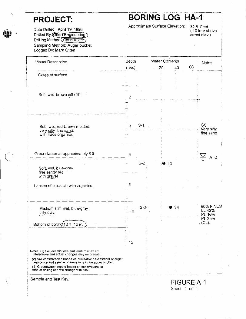
PROJECT:
Visual Description
Grass at surface.
Soft, wet, brown ~t (fill).
BORING LOG HA-1-- ---1 Approximate Surface Elevation: 32.5 Feet.
Depth
(feet)
Water Contents
20 40
( 1 O feet above street elev.)
Notes 60
I
I r-- -------------
Soft, wet red-brown mottled. very silty, fine sand. · with trace orgarir"cs.
Groundwater at approximately 6 ft.
Soft, wet, blue-gray fine sanq_y aj_lt with gr?yel.
Lenses of black silt with organics.
4 S-1 . GS: ------------------------------------Very silty,
fine sand.
6 · 2': ATD -S-2 - ?" -,_...,
--- 8
! ----------
Medium stiff wet, biue-gray, silty clay.
S-3! • 34 80% FINES LL42%
·-------------- PL 16%
; I
I
/ Bottom of boringJ Q ft 1 o ir0
Notes: (1) Soil descriotions and stratum iines are interpretive and actual changes may be gradual.
(2) Soil consistencies based on qualitative assessment of auger resistance and sample observations in the auger bucket. (3) Groundwater depths based on observations at time of drilling and will change with time.
= 10
- 12
Pl 25% (CL).
-- --·----------------------- -------------- ------------ -------Sample and Test Key.
FIGURE A-1 Sheet '1 of 1

c ..
PROJECT: BO-RING-LOG ___ HA~ Approximate Surface Elevation: 22.~ F:t \
(Street elev.) Date Drilled: April 19, 1996 Drilled By: Otten Engineering Drilling Method: Hand Auger Sampling Method: Auger bucket Logged By: Mark Otten
r--I Visuai Description
Gravel at surface.
Soft, wet, blue-gray, slighly sandy silt with gravel.
Groundwater at approximately 2 ft.
Lenses of black silt with organics
'.Depth Water Contents I
i (feet) 20 40 -··---·-·--l----··--···-- - - -------------- .. ~-·
~2 -+····-······-·----.------.-·-··--- ----
1 .
' -·-:-,
------;,..._
Loose. wet, gray. fine sand.
Soft, wet brown, organic silt, with pieces of timber in silty sand matrix.
Medium stiff, wet. blue-gray clayey silt.
Bottom of boring 8 ft. 6 in.
, __ S-1
6
-s S-2
'- 12
Notes: ( 1) Soil descriptions and straturr Imes are t
interpretive and actual changes may be gradual. I (2) Soil consistencies based on qualitative assessment of auger ',
Notes 60
(3) Groundwater depths based on observations at : resistance and sample observations in the auger bucket. L_' time of drilling and will change with time. -~---· :-------------------,-
Sample and Test Key. FIGUREA-2 Sheet 1 of 1

•.
• PROJECT: Date Drilled: April 19, 1996 Drilled By: Otten Engineering Drilling Method: Hand Auger Samp1ing Method: Auger bucket Logged By: Mark Otten
Visuai Description
Soil at surface. Soft. wet. red-brown mottled. very silti fine sand, with trace organics. / - - - - - -______ ./ Soft. wet, black. organic silt, with rcrten wood pieces.
BORING LOG HA-3 ___ 1 Approximate Surface Elevation: 38.5 Feet
I
I Depth
(feet)!
water Contents
20 40
(6 feet above north yard
Notes 60
' ' . ---- --~---- ------·--·-------------<
' 4 ··- - - - - - - - - - - - - -: Groundwater at approximately 4.5 ft.
!
II
Soft wet, blue-gray, fine sandy siit to silty, fine sand.
Graces to medium stiff
Bottom of boring 8 ft '.J ,n.
Notes: (1) Sod descriptions and srratu,.., lines are I interpretive and actual changes may oe gradual.
1
1
(2) Soil consistencies based on quaiitative assessment of auger
I resistance and sample observations in the auger bucket. (3) Groundwater depths based on observations at
I time of drilling and will change with time. l I Sample and Test Key.
6
S-1 ' -- 8
= 10
• 33
SZ ATD -
GS sandy silt
FIGURE A-3 Sheet 1 of 1

C
f \.._
•. ;,-PR_O_J_E_C_T_: ----, BORING LOG HA-4--l Date Drilled: April 19, 1996 Drilled By: Otten Engineering Drilling Method: Hand Auger
Sampling Method: Auger bucket Logged By: Mark Otten
Visual Description
Gravel at surface. Loose, damp, brown, gravel.(fill)
·--- - -----------Groundwater at approximately 3.5 ft
Soft, wet, blue-gray, ciyaey silt.
Soft to medium stiff, wet, blue-gray, slighly sandy silt to silty, fine sand, with small wood pieces.
Bottom of boring 7 ft. 0 in.
Noies: (1) Soil descrioiions and s,ratum lines are interpretive and actual changes may be gradual.
(2) Soil consistencies based on qualitative assessment of auger resistance and sample observations in the auger bucket. (3) Groundwater depths based on observations at time of drilling and will change with time.
Sample and Test Key.
1 Approximate Surface Elevation: 31.0 Feet
( about 8 feet above street)
:oepth
: (feet)
l.--2
4
i '
6
-s
:- 12
S-1
i I
I i
I I
I
Water Contents
20 40 60 Notes
SZ: ATD ~~~-~~~-~~~-
FIGURE A-4 Sheet 1 of 1

•.
SIil LEITER OF TRANSMITTAL
TO:
SUBJECT:
Mark Otten 3029 NE 182nd Seattle, Washington 98155
Morrell project
Date: 4/30/96 Job No.: J-902
RE: Sample ID No. HA-1 S-2, HA· 1 S-3, HA-2 S-1, HA-2 S-2 and HA-3 S-1
We are sending the following items:
Date Copies Description 4/30/96 2 Moisture Contents (Table 1) 4/30/96 2 Material PassinQ No. 200 Sieve (Table 2) 4/30/96 2 Grain Size Analyses (Figure 1) 4/30/96 2 Atterberg Limits (Fiqure 2) 4/30/96 1 OriQinal Invoice No. 125 9
These are transmitted for your use.
Remarks: Samples were tested in general accordance with ASTM D-2216, ASTM D-1140, ASTM D-4318 and ASTM D-422. Please call if you have any questions regarding this submittal or presentation of the data. Thank you.
Best Regards,
SOIL TECHNOLOGY. INC.

•'
Exploration Number
HA-1
HA-1
HA-2 -·
HA-2
HA-3
Morrell Project Project No. 9622
Table 1: Moisture Contents
Sample Number Depth
(ft)
S-2 6'4"
S-3 10'10" --S-1 4'0"
S-2 8'0"
S-1 7'6"
'Moisture Content analysis performed following ASTM D 2216 methodology.
Table 2: Material Passing No. 200 Sieve
Exploration Number Sample Number Depth
(ft)
HA-1 S-3 10'10"
·-
-----· ·--- ------- - --- -- . --.~- ----- -·-· ------------·-· HA-2 S-2 8'0"
2 Percent Passing No. 200 analysis performed following ASTM D-1140 methodology.
Moisture Content1
(%)
23
34 --------
19
25
33
% Passing No. 200
Sieve (75 micron)2
80 ----- ·-------------
67
Soil Technology, Inc. J-902
Page 1

I
I
-- --- -·-r
I Soil Technology, Inc.
L ·-----·--· - ·-·---------··-··-·· -------- _____ J __ I I i
i
Symbol -e··tr
'·' .r ~-! [ l
:~~ i i l ! ; .
o +H +--r I 00(1 500
lcouo,, ·
~TTT+-+·, .. _ _l I ;
; i ... '.\; i;
: I l :I•.; i: l i.
' !
, . ---1tL..,.., r-
100 5ci
lfo:ing No. HA-2
Sarn11le No. s--1
Depth 4'0 7'6 I 1/1 3 ,-.;o ·
Project Hc,rrell ProJect tfo. g,=:?2
Grain Size Analysis Project r,n ,; 902
Location:
Date f.i,,11 ;\pr 29 1C::9f. ·----------- -L------------- -·--·-------- -------- - -------------- .. -----------·- - - 1
#4
.! .... \ nTJ~r y 4',._;~:---_-___ -~;..i-~,:...,_L~~~f"": ~~;~ ~
'. ' . . ! .- l ~
! i 111 ----y,t,-;--r--, -t -
10 5
CRAiN • '!
\
' .. ' . '
----t,,-;-+.-~~ 1 0.5
IN MIU .. IMf: l l i,
' - .. ,.Jr 1 1 • ..
i; t: ; . 1;. ! i
i---.
·irr+-;---,,--,----, 0.1 0.0::
J:}
Iii I I
0.01 0.005
--------------- -----·------ ---- ..... ·------------------Filename HA2S1 1iA3S1
Clc'.csification / De:,cription Silt,/Clarey sand Sn,1-:!y silt/clay
40
- 60
--j 70
BG
90
·-i-· JOO
0.001
c:, Ld z <t: f-w (Y
~z w u O:'. u..l [.L
Classification/D~riction based on arain size onlv. No Atterbero. Limlt6-Der1orme(L ____________ __ .... ______ _
I
l !
'\