the effect of die exit curvature, die surface roughness ...€¦ · the effect of die exit...
TRANSCRIPT

J. Non-Newtonian Fluid Mech. 126 (2005) 47–61
The effect of die exit curvature, die surface roughness and a fluoropolymeradditive on sharkskin extrusion instabilities in polyethylene processing
D.R. Arda, M.R. Mackley∗
Department of Chemical Engineering, University of Cambridge, New Museums Site, Pembroke Street, Cambridge CB2 3RA, UK
Received 3 March 2004; received in revised form 24 September 2004; accepted 20 December 2004
Abstract
This paper reports experimental observations and numerical simulations relating to sharkskin extrusion instabilities for two different typesof polyethylene, a metallocene high-density polyethylene (HDPE) and a linear low-density polyethylene (LLDPE). Experimental results arepresented for both the effect of die exit curvature and die surface roughness for slit die geometry. Matching polyflow numerical simulations arealso reported and are shown to be qualitatively consistent with experimental observations. The onset of the sharkskin instability is correlatedwith the magnitude of the stress concentration at the die exit, and is found to be sensitive to both the melt/wall separation point for a curvedexit die, and the level of partial slip at the die wall. Additional observations on the effect of a fluoropolymer additive also support the sensitivityo©
K
1
bihnhotie
1
isg
t the
skinr theessct ofd be-
ac-flowf therestusesn these toto aThisskinisual
0d
f the sharkskin instability to partial slip at the wall.2005 Elsevier B.V. All rights reserved.
eywords:Sharkskin; Instability; Polyethylene; Extrusion; Curved exit dies; Die surface roughness; Fluoropolymer; Slip
. Introduction
This paper is concerned with sharkskin extrusion insta-ilities for polyethylene and investigates ways of minimising
ts occurrence. Sharkskin is generally described as fine-scale,igh frequency, small-amplitude distortions or surface rough-ess (see, for example[1–3]). The instability can appear atigh shear stresses for certain polymers and can hinder theptical and mechanical properties of the polymer product,
hereby limiting the rate of polymer production. The subjects of both scientific and commercial interest and has beenxtensively reviewed by[1–6].
.1. Sharkskin origin
Although there have been numerous studies on sharkskinnstabilities over the past 50 years, there is still no clear con-ensus as to the exact mechanism that causes its onset. It isenerally accepted that, whatever may be happening within
∗ Corresponding author. Tel.: +44 1223 334777; fax: +44 1223 334796.
the die, overriding experimental evidence shows thasharkskin instability originates at the die exit[7,8]. A grow-ing number of researchers believe that the origin of sharkis related to local stress concentrations in the melt neadie exit[9–12]. However, the mechanism by which the strconcentrations actually cause sharkskin is still a subjedebate. A number of proposed mechanisms are outlinelow.
1.1.1. Rupture mechanismsCogswell[9] proposed that the polymer extrudate fr
tures at the die exit due to an abrupt change in theboundary conditions. He explained that downstream odie exit, the surface layer of the melt accelerates fromto the average extrusion velocity. The acceleration caa stretching flow, producing tensile stresses higher thatensile strength that the material can withstand, giving ricracking of the surface at the exit, which in turn leadsmomentary relaxation of flow conditions near the edge.continues in a cyclic manner, giving rise to the sharkphenomena. This explanation is consistent with the v
E-mail address:[email protected] (M.R. Mackley). observations made just at the die exit by El Kissi and Piau
377-0257/$ – see front matter © 2005 Elsevier B.V. All rights reserved.oi:10.1016/j.jnnfm.2004.12.005
48 D.R. Arda, M.R. Mackley / J. Non-Newtonian Fluid Mech. 126 (2005) 47–61
[11], who reported the appearance of cracks perpendicularto the flow direction. In addition, Rutgers and Mackley[12]proposed that a rupture mechanism could explain the corre-lation between sharkskin and melt strength. The mechanismis supported by numerous authors[8–15].
Legrand and Piau[16] and Inn et al.[15] attributed shark-skin to a layer of polymer melt close to the die wall stickingto the rim of the die exit as it is extruded with die swell.The outer layers of the melt stick to the exit rim and theinner layers move with the extrudate. They claim that thesurface fracture begins in a form of peeling. After the ridgehas grown to a certain size, it is torn from the die exit andmoved forward with the whole extrudate, and immediatelya new ridge starts at the rim of the die exit. In support ofthis model, Inn et al. found that dies with a sharp exit in-duce uniform and well-defined sharkskin ridges, because thesurface layer of the melt can stick to only one fixed po-sition on the die edge. The extrudates from rounded exitdies, however, have non-uniform ridges, because the surfacelayers appear to stick arbitrarily on the surface of the exit[15].
1.1.2. Slip mechanismsIn 1986, Ramamurthy[17] carried out measurements us-
ing a technique outlined by Mooney[18] and demonstratedthat for certain polymers, partial slip occurs at the die walla guedt rt of ac walls ilureo and.K seto e fora sedb ism,w pearste flu-o buts gler ea ccuru slipo
nsi larl n oc-c diew erfa-c t andd tran-s nd-a andg welli ex-t micso cor-
relate precisely with molecular chain relaxation dynamics[22–24].
Molenaar and Koopmans[25] proposed a local mecha-nism of stick-slip or relaxation oscillations in a thin periph-eral layer near the die exit, similar to the oscillating defectobserved at higher stresses. They modelled melt flow instabil-ities in terms of cyclic relaxation oscillations, during whichpotential energy is successively stored and relaxed, and foundthat above a critical wall shear stress, the increase in the flowcurve becomes non-monotonic and successive stick-slip os-cillations develop within a localised area at the die exit.
An alternative local stick-slip mechanism for LLDPE wasproposed by Dhori et al.[26–28], who attributed stick-slip tothe dewetting-wetting process between the melt and the diewall at the die exit corner. They asserted that the dewettingwas the result of exceeding a critical surface elastic energy,while the rewetting was the result of a relaxation process.According to this mechanism, sharkskin is suppressed bylocal die exit coatings such as PTFE, because the coatingforms a relatively low energy solid surface that the polymercannot rewet[28].
Joseph and Liu[29], on the other hand, suggested that theasymmetric aspect of sharkskin could result from a thin lubri-cating layer (which, for example, could be a molecular massfraction of the polymer) with a steep wave front. Joseph[30]argued that this lubricating layer allows the polymer melt tos aves,s d byw
thatp nsis-t e orst h theo eda exit,a chedw ang[ skinr d oft ucedo tiono at thed
1se to
t cesb uces
1
1, or
p e of
bove the critical shear stress for sharkskin. He then arhat the several categories of extrudate distortion are paontinuum behaviour associated with the occurrence oflip, and that the first onset of sharkskin occurs with a faf adhesion at the melt/die wall interface along the die lalika and Denn[19] also showed evidence that the onf sharkskin and the apparent curvature of the flow curvlinear low-density polyethylene (LLDPE), are both cauy partial slip of the melt at the die surface. This mechanhich proposes that sharkskin is enhanced with slip, ap
o be inconsistent with results of Migler et al.[20] and Yangt al.[21], who show that the presence of a thin layer ofropolymer at the melt/die wall interface enhances slipuppresses sharkskin, rather than causes its onset. Mil. used optical velocimetry to show that sharkskin can onder a variety of melt/wall boundary conditions: stick,r oscillating stick-slip[20].
Wang and Drda[22] explained the sharkskin distortion terms of melt/wall interfacial interactions at a molecuevel. Their proposed mechanism states that sharkskiurs because of a local conformational transition at theall exit, where the adsorbed chains entrap a layer of intial chains. This layer oscillates between entanglemenisentanglement states due to a reversible coil-stretchition. The corresponding oscillation of the exit wall boury condition leads to cycles of local stress relaxationrowth, and to periodic perturbation of the extrudate s
n the form of sharkskin-like surface roughening on therudate. In support of this mechanism, sharkskin dynaf linear low-density polyethylene has been found to
t
lip along the die wall, creating sharp steep (sharkskin) wuch as those that appear on flows of heavy oil lubricateater.Both the melt fracture mechanism, and the mechanism
roposes local stick-slip of the melt at the die exit, are coent with observations of local oscillations of birefringenctress fringes at the die exit. Legrand and Piau[16] observedhat the onset of these stress oscillations coincided witnset of the sharkskin instability for PDMS. They viewnd recorded periodic cracking of the melt at the diend found that the period of the stress oscillation matith the sharkskin crack formation period. Barone and W
31] observed birefringence oscillations during the sharkegime of polybutadiene and also found that the periohe oscillations agreed with the period of the ridges prodn the sharkskin extrudate. They explain that the oscillaccurs because of the unstable slip boundary conditionie exit[31].
.1.3. Other mechanismsTremblay[32] suggested that negative pressures clo
he die exit could induce the formation of vacuum spay cavitation, the coalescence of which would then prodharkskin instabilities.
.2. Current sharkskin minimisation methods
.2.1. AdditivesThe most common method of eliminating sharkskin
ostponing it to higher flow rates, has been the us

D.R. Arda, M.R. Mackley / J. Non-Newtonian Fluid Mech. 126 (2005) 47–61 49
polymer processing additives (PPA), such as a fluoropoly-mer. When a fluoropolymer is blended into polyethylene inan extruder, it has been found that the fluoropolymer be-comes dispersed in the polyethylene in the form of spher-ical droplets, 0.1–0.5�m in diameter[33]. The fluoropoly-mer was found to be incompatible with the polyethylene,causing a uniform, continuous coating of strongly adheredfluoropolymer, of the order of 1�m thick, which was de-posited during extrusion on the extruder screw, barrel anddie surfaces[34]. No fluoropolymer was found on the sur-face of the polyethylene after extrusion, suggesting that asharp interface existed between the fluoropolymer coatingand the polyethylene melt during extrusion. It appeared thatfluoropolymers act as processing aids by forming a thin uni-form coating on die surfaces, which provides a sharp, lowenergy interface over which, at sufficiently high shear stress,the polyethylene can slip[34]. It has also been discoveredthat fluoropolymer can act either as an adhesion promoteror as a slip promoter, depending on the coating method[35]. If the coating method results in a porous fluoropoly-mer coating, this enhances melt/die wall adhesion, whereasif the method results in a non-porous coating, slip is pro-moted.
A more recent processing additive that was found tosignificantly delay the onset of sharkskin is boron ni-tride (BN) [36]. The authors found that the addition ofa rk-s theo ues[
1rial
s con-sR iono tt rebyr ung[ undp ghert t arel undt h toa rface[
diee oly-m eri-m pre-s aree eres anda thy-l bili-t
2. Experimental
2.1. Materials
The two materials studied were Dowlex NG5056E lin-ear low-density polyethylene supplied by Dow Benelux B.V.and a metallocene development grade high-density polyethy-lene homopolymer supplied by Repsol YPF. The HDPE wassupplied both without and with a fluoropolymer additive sup-plied by Dyneon GmbH. The LLDPE was chosen as a refer-ence comparison to the HDPE. Material properties of thepolymers are given inTable 1 and the linear viscoelasticspectrum parameters and a non-linear Wagner damping fac-tor obtained from rheological characterisation are given inTable 2(see[41] for details on how this data was obtained).The Dowlex LLDPE was a heterogeneous blend of linearpolyethylene and polyethylene chains with varying numbersof octene-1 branches. Its main application is in blown filmextrusion. The fluoropolymer was a linear random terpoly-mer of tetrafluoroethylene (40 mol%), hexafluoropropylene(10 mol%) and vinyldenfluoride (50 mol%). Its main appli-cation area is within the automotive industry where it is usedin hose applications under the bonnet.
Preparation of the fluoropolymer as a polymer-processingadditive to the HDPE was carried out in the following way. Amaster-batch of 30,000 ppm (3%, w/w) fluoropolymer/HDPEw d tot 5%,w ooni r toa thee h thes . The1
2
mms de-s peedtt thata datew on-t
win-d forfl usedw hro-m iser,o n,a ofd andr
peri-m
composition of fine particles of BN eliminated shakin as well as postponed the critical shear rate fornset of gross distortion to significantly higher val
37].
.2.2. CoatingsCoating the die wall with a low surface energy mate
uch as PTFE has been found to eliminate, or at leastiderably delay the sharkskin instability[17,38,39]. Whileamamurthy[17] attributed this result to increased adhesf the melt to the die wall, Piau et al.[38] proposed tha
he coating material promotes slip at the die wall, theeducing the exit stresses. Recently, Kulikov and Horn40] found that coating the die land with a rubber comporoduced defect-free extrusion, for flow rates 10 times hi
han those in Teflon dies. Coatings of PTFE or rubber thaocalised just at the exit of the die wall, have also been foo be effective at delaying the onset of sharkskin, thoug
lesser extent than a coating along the whole die su38,40].
This paper systematically explores the effect thatxit curvature, die wall surface roughness and a fluoroper additive have on sharkskin instabilities. Both expental results and matching numerical simulations are
ented. Two distinctly different types of polyethylenexamined, namely a commercial grade of LLDPE whharkskin instabilities have been observed previouslydevelopmental grade metallocene high-density polye
ene (HDPE) that shows pronounced extrusion instaies.
as supplied by Dyneon. This master-batch was dilutehe final recommended concentration of 1500 ppm (0.1/w) by shaking and stirring the mixture with a large sp
n a container for 5 min to ensure homogeneity. In ordeid the deposition of additive on the internal walls ofxtruder and die, the master-batch was extruded througystem until a reduction in pressure drop was observed500 ppm batch was then extruded subsequently.
.2. Extrusion apparatus
Extrusion experiments were carried out using a 25ingle screw extruder equipped with a melt gear pumpigned to control the flow rate and the extruder screw shrough a pressure feedback system (see[41] for further de-ails). The dies were held in a stainless steel flow cellllowed interchangeable die inserts. The polymer extruas hauled off vertically using a haul off machine with c
rollable rotational speed.The flow cell was designed to accommodate optical
ows, which would enable the set-up of an optical line-upow birefringence measurements. A mercury lamp wasith a 546 nm wavelength (green) filter to provide monocatic light. The flow cell was placed between a polarriented at 45◦ with respect to the principle flow directiond an analyser, oriented at−45◦. The transmitted pictureark and light bands were captured by a CCD cameraecorded onto video.
The features of the various die inserts used in the exents described in this paper are summarised inTable 3. All

50 D.R. Arda, M.R. Mackley / J. Non-Newtonian Fluid Mech. 126 (2005) 47–61
Table 1Physical properties of the LLDPE, HDPE and the fluoropolymer
Material Dowlex LLDPE NG5056E HDPE 0017 ZSK Fluoropolymer THV220G
Supplier Dow Benelux B.V Repsol YPF Dyneon GmbHDensity (g/cm3), RTP 0.9195 0.9521 1.937Mn (g/mol) 54,800 53,400 46,900Mw (g/mol) 113,000 122,900 75,000Mw/Mn 2.1 2.3 1.6
Table 2Spectrum coefficients{gi , λi} and damping factors,k for the LLDPE, HDPE and the fluoropolymer
LLDPE HDPE FP
λi (s) gi (Pa) λi (s) gi (Pa) λi (s) gi (Pa)
2.09× 10⁻³ 2.43× 10⁵ 2.00× 10⁻³ 3.38× 10⁵ 2.11× 10⁻³ 1.88× 10⁵
9.51× 10⁻³ 1.44× 10⁵ 9.38× 10⁻³ 2.28× 10⁵ 9.27× 10⁻³ 2.04× 10⁵
4.32× 10⁻² 5.34× 10⁴ 4.40× 10⁻² 7.05× 10⁴ 4.07× 10⁻² 1.17× 10⁵
1.96× 10⁻¹ 1.25× 10⁴ 2.06× 10⁻¹ 1.06× 10⁴ 1.79× 10⁻¹ 3.30× 10⁴
8.90× 10⁻¹ 2.08× 10³ 9.69× 10⁻¹ 1.30× 10³ 7.86× 10⁻¹ 5.36× 10³
4.04× 100 2.83× 10² 4.54× 100 2.18× 10² 3.45× 100 1.00× 10³
1.84× 101 2.24× 101 2.13× 101 1.73× 101 1.52× 101 1.29× 10²
8.33× 101 9.59× 10⁻⁶ 1.00× 10² 1.37× 10⁻⁵ 6.67× 101 1.54× 101
k= 0.21± 0.02 k= 0.23± 0.04 k= 0.37± 0.05
dies had curved entries, a parallel die length of approximately8 mm, and die gaps of 1.2 mm and die depths of 15 mm. DiesA–C had identical surface roughness of 1.5�m centre lineaverage (CLA). The first die had a conventional 90◦ exit (dieA); the others were radiused such that their exits are curvedat 0.8 mm (die B) and 2 mm (die C), respectively.
Dies D–F had different surface roughness. Die D had amedium finish of 1.5�m CLA, die E had a semi-polishedfinish of 0.7�m CLA and die F had a technically polishedfinish of 0.05�m CLA. The dies had curved exits of radius0.8 mm similar to die B. The dies were assembled ensuringsimilar gap widths of 1.2 mm. The accuracy of the slit widthwas controlled by tightening the inserts with a feeler gauge inplace, such that the feeler gauge could only just be removedwithout friction.
Flow rates in this paper are given in RPM, correspond-ing to the melt gear pump speed. Corresponding mass flowrates can be obtained usingFig. 1. Volumetric flow rates werecalculated assuming a melt density of 760 kg/m3.
The extrudates were examined using scanning electron mi-croscope (SEM) and surface profilometry techniques. SEMwas carried out using a Leica Stereoscan 430 scanning elec-tron microscope. The profilometer was a contact roughnessmeasurement technique that consisted of a stylus with a small
tip that was automatically traversed along the surface to beexamined. As the stylus moved up and down along the sur-face, a transducer (pick-up) converted this movement into asignal that was then exported to a processor that convertedthis into a number and a visual profile. A Talysurf six instru-ment was used with a standard diamond cone stylus with acone angle of 90◦ and a tip radius of 2�m. The pick-up usedwas a 112/2033-P3. Surface roughness values in this paperare given as Rq, defined as the root mean square roughnessvalue of a profile.
Fig. 1. Plot of mass flow rate vs. melt gear pump speed for extrusion of theLLDPE at 190◦C through dies A–F and for the HDPE at 190◦C through dieA.
TD experi
C
2 rad1.
C
able 3ie exit and surface roughness features of the die inserts used in the
Features Dies
A B
Die exit 90◦ 0.8 mm radSurface roughness (�m CLA) 1.5 1.5
LA, centre-line average.
ments described in this paper
D E F
mm rad 0.8 mm rad 0.8 mm rad 0.8 mm5 1.5 0.7 0.05

D.R. Arda, M.R. Mackley / J. Non-Newtonian Fluid Mech. 126 (2005) 47–61 51
3. Numerical simulation
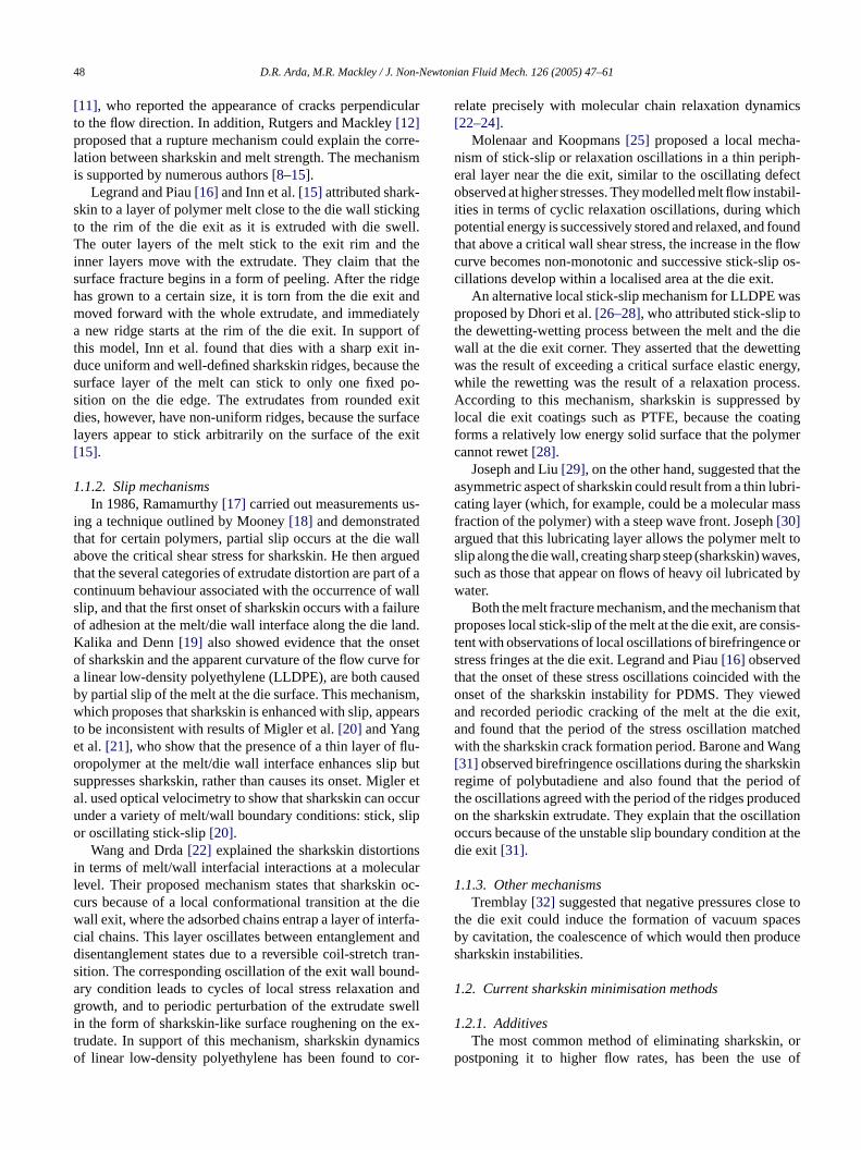
Numerical simulations were carried out using the com-mercial finite element CFD package polyflow. Simulationsused the KBKZ integral equation with the Wagner irreversibledamping factor to predict principal stress differences (PSD)values in the melt flowing through the die (see for exam-ple [12]). Meshes were constructed with a 90◦ exit angle, a0.8 mm radiused exit and a 2 mm radiused exit, correspondingto the dies used experimentally. In order to carry out simu-lations of the radiused exit dies, it was necessary to spec-ify the separation points of the melt from the die. This wasdone using data from the matching experimental observa-tions and meshes were generated with these experimentallyobtained separation points. All meshes were designed with30�m× 30�m size elements at the die wall at the die exitand are shown inFig. 2. The parameters used in the numericalsimulations were for LLDPE and HDPE at 190◦C and at aflow rate of 2.4× 10⁻⁷ m3/s. This was a typical high exper-imental extrusion flow rate within the sharkskin regime andcorresponded to a wall shear stress of approximately 0.2 MPa.
The finite element formulation in polyflow used quadraticinterpolation for velocities and linear interpolation for pres-sure. The boundary conditions assumed were a fully devel-oped flow 25 mm upstream of the slit entrance before thecurved entry region, with initially no slip at the die wall. Thec ys menti2 -s qual-i ands linesc esew
withd los-e ath-e tt pre-d ever,i2 it,t near-e ev forec s ob-t wall,w %a ed ade arriedo
f thed ,p d inl exit
is the point of the abrupt change in boundary condition, aswell as the point of maximum PSD, it would seem reasonableto expect that this is the point where sharkskin is initiated.Manifestation of the sharkskin characteristics would be ex-pected to take place slightly downstream of the die exit, sinceit would take a finite time for the wave to propagate within themelt. Venet and Vergnes[44], however, used a finite elementmethod incorporating the Phan-Thien and Tanner constitu-tive equation to predict the tensile or extensional stresses inthe melt in the die exit region and found that the maximumextensional stress actually occurred slightly downstream ofthe die exit at the surface of the melt. They proposed that theactual rupture of the melt occurs at this position of maximumextensional stress, downstream of the die exit.
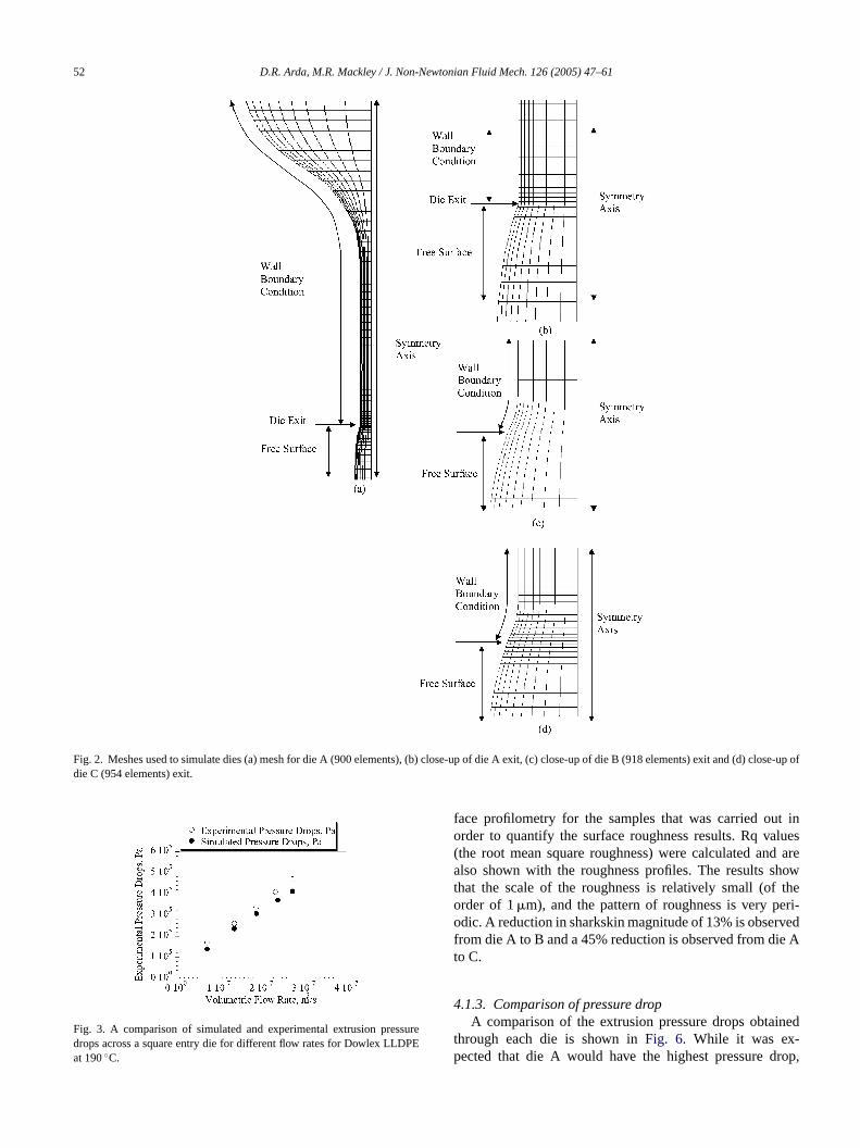
Quantitative matching of experimental and simulatedstress birefringence and extrusion pressure drops for the ex-perimental die geometries presented in this paper has not beenmade. However, a quantitative matching of extrusion pressuredrop has been carried out for the same material LLDPE andat the same temperature of 190◦C for different die geometryand this is shown inFig. 3.
4. Results and discussion
4.1. The effect of die exit curvature
4gh
d owni eres heres er off f thed to thed achd f thed tionsa iblet f them idtha layedf ionsa
4C at
0 ltso imew wasn B,t dieC isu-a ars d0 r-
onvergence criterion was set to 10−3. A mesh sensitivittudy investigated three meshes refined such that the elemmediately at the wall at the exit were 30�m× 30�m,0�m× 20�m and 15�m× 15�m, respectively. The reulting streamlines and global stress contours weretatively compared and the pressure drops, velocitiestresses along the centreline and the PSD along streamlose to the die wall were quantitatively compared. There found to match across the three dies.A difference in the solution between the three meshes
ifferent exit element sizes only occurred in the element cst to the wall at the exit. This was the consequence of a mmatical singularity at the die exit[42,43]. It was found tha
he more refined the mesh, the higher the numericallyicted stress in the one node adjacent to the wall. How
n the present study, for the element sizes of 30�m× 30�m,0�m× 20�m and 15�m× 15�m at the die wall at the ex
he exit PSD peaks were calculated outside the elementst the wall, along streamlines 50�m from the wall, and thesalues were found to agree to within 2%. It was, thereoncluded that mesh independence of the simulation waained outside the element immediately adjacent to thehich in this case was 30�m for the coarsest mesh. The 2greement in the values of the PSD peaks was considerquate and subsequent simulations were, therefore, cut with meshes having exit element sizes 30�m× 30�m.
The mathematical singularity occurs at the corner oie wall. Tracking along a streamline 50�m from the die wallolyflow predicted that the maximum PSD also occurre
ine with the die wall corner. Since the corner of the die
s
-
.1.1. Stress fieldFlow birefringence images of LLDPE extruded throu
ies A–C, which had different die exit curvatures, are shn Fig. 4. The images are for a lower flow rate than that whharkskin occurs because the high flow rate images, wharkskin does occur, are unclear due to the high numbringes. The images show that in the parallel section oie, the fringes and therefore the stresses are parallelie wall. An identical number of fringes are observed in eie, showing that the stresses in the parallel section oies are of equal magnitude. The local stress concentrat the die exit are difficult to resolve; however, it is poss
o see that with curvature of the die exit, separation oelt from the die no longer occurs at the smallest gap wnd the separation is delayed. The separation is more de
or die C than die B. Qualitatively, the stress concentratppear to be lower for the curved exit dies.
.1.2. Extrudate surfaceSEM images of the extrudate surfaces from dies A–
.6 rpm are shown inFig. 5. The images show the resuf extrusion at moderately high flow rates in a flow reghere sharkskin occurs. It was observed that while thereot a significant reduction in sharkskin from die A to die
here was a definite reduction in sharkskin from die A to. The onset of the sharkskin instability, as observed vlly from SEM, was as follows: 0.4 rpm for die A (wall shetressτw = 0.14 MPa), 0.4 rpm for die B (τw = 0.16 MPa) an.6 rpm for die C (τw = 0.17 MPa).Fig. 5 also shows su
52 D.R. Arda, M.R. Mackley / J. Non-Newtonian Fluid Mech. 126 (2005) 47–61
Fig. 2. Meshes used to simulate dies (a) mesh for die A (900 elements), (b) close-up of die A exit, (c) close-up of die B (918 elements) exit and (d) close-up ofdie C (954 elements) exit.
Fig. 3. A comparison of simulated and experimental extrusion pressuredrops across a square entry die for different flow rates for Dowlex LLDPEat 190◦C.
face profilometry for the samples that was carried out inorder to quantify the surface roughness results. Rq values(the root mean square roughness) were calculated and arealso shown with the roughness profiles. The results showthat the scale of the roughness is relatively small (of theorder of 1�m), and the pattern of roughness is very peri-odic. A reduction in sharkskin magnitude of 13% is observedfrom die A to B and a 45% reduction is observed from die Ato C.
4.1.3. Comparison of pressure dropA comparison of the extrusion pressure drops obtained
through each die is shown inFig. 6. While it was ex-pected that die A would have the highest pressure drop,

D.R. Arda, M.R. Mackley / J. Non-Newtonian Fluid Mech. 126 (2005) 47–61 53
Fig. 4. Flow birefringence images for the LLDPE extruded at 0.05 rpm and 190◦C through dies (a) A, (b) B and (c) C.
the greatest pressure drop was actually found for die B.However, the differences between pressure drops for thethree dies are small in comparison to the experimental er-ror of 10%, which appears to be high as it takes into ac-count the pressure drop variation that occurred with the un-steadiness of the extrusion temperature and also dependingon whether the flow rates were being increased for the firsttime or after they had been increased and decreased a fewtimes.
4.1.4. Stability of the melt/wall separation pointExtrudates from the curved exit dies appeared to emerge
in a waveform, swaying from side to side with a time periodof the order of seconds. This effect appeared to be more en-hanced for the die with the most highly curved exit (die C)and was not observed for the die with the conventional 90◦exit (die A). An explanation for this effect could be the in-stability of the separation point between the melt and the diewall at the exit. While for 90◦ exit dies, the melt separates
F(
ig. 5. SEM images and surface profilometry profiles with Rq values for extrb) B and (c) C.
udate surfaces of the LLDPE extruded at 0.6 rpm and 190◦C through dies (a) A,

54 D.R. Arda, M.R. Mackley / J. Non-Newtonian Fluid Mech. 126 (2005) 47–61
Fig. 6. Pressure drops across dies A–C for extrusion of the LLDPE at 190◦Cat varying flow rates.
from the die at a sharp position (the corner of the die exit),with curved exit dies it is possible for the melt to separate ata wider range of positions. It is possible that this latter fea-ture promotes the extrudate to emerge in a wavy formation.Furthermore, it could be conjectured that this also extends tocases of smaller scale. If the stability of the melt/wall sep-aration point for 2 mm radiused exit dies generates waveswith wavelengths of the order of centimetres (as was ob-served experimentally), it is not inconceivable that a sharp90◦ exit could generate sharkskin waves of the order of mi-crons. This could be one of the factors, in addition to thestress concentration, that are involved in the mechanism be-hind the sharkskin instability, as proposed by Dhori et al.[26–28].
4.1.5. Numerical simulationIn order to investigate the stresses in the melt at the die
exit, simulations were carried out to observe the principalstress differences values along streamlines 50�m from thedie wall. The results are shown inFig. 7. The plots show thatthere is a PSD peak at the die exit due to the abrupt change inboundary condition of the melt as it leaves the die. The resultsalso show that with the delayed separation of the melt fromthe die exit, the PSD peak for die C is lower than that of dieB, which in turn is lower than that of die A. This correspondsto the experimental result that the magnitude of sharkskini dieA
4sig-
n usedi theL elys paredt eref im-a thatw dies,t muchl ea-s of thee o the
Fig. 7. PSD values along streamlines 50�m from the die wall simulated inpolyflow for the LLDPE at 190◦C through dies (a) A, (b) B and (c) C.
extrudate from die A. Die exit curvature was, thus shown to bea viable method of minimising sharkskin for both the LLDPEand the HDPE. A disadvantage of this method, however, isthat it would not be suitable for applications where precisionof the extrudate profile is of importance, since accuracy ofthe extrusion profile is not as high as for a sharp die exit.However, die exit curvature could be suitable for applica-tions such as film production, where control of the extrusionprofile could be compensated for by increased draw down.
4.2. The effect of die surface roughness
4.2.1. Stress fieldIn this set of experiments the die geometry was held con-
stant and the surface roughness of the inside of the die wallvaried. All exits were radiused to a 0.8 mm curvature.Fig. 8shows the flow birefringence images captured for extrusionof LLDPE through dies D (most rough surface), E and F(least rough surface) at 0.05 rpm and 190◦C. In the parallelsection of the die, the fringes and therefore the stresses areparallel to the die wall. Die F appears to have fewer fringesthan dies D and E indicating that the stresses are lower in
s lower for die C than die B, and lower for die B than.
.1.6. Polymer materialThe metallocene HDPE, which was found to exhibit
ificantly severer sharkskin than the LLDPE, was alson extrusion experiments through dies A and C. As withLDPE, the HDPE birefringence stress field qualitativhowed a smaller stress concentration for die C as como die A. The extrusion pressure drops through die C wound to be at least 20% lower than through die A. SEMges of the resulting HDPE extrudate surfaces showedhile sharkskin was present for extrusion through both
he sharkskin magnitude through die C appeared to beower. This was quantified using surface profilometry murements, which showed that the surface roughnessxtrudate from die C was reduced by 70% compared t

D.R. Arda, M.R. Mackley / J. Non-Newtonian Fluid Mech. 126 (2005) 47–61 55
Fig. 8. Flow birefringence images for the LLDPE extruded at 0.05 rpm and 190◦C through dies (a) D, (b) E and (c) F.
the smoother dies. It can also be observed that the separationpoint of the melt from the die appears to be delayed furtherfor die E as compared to die D and for die F as compared todie E. This last result is unexpected, as it was anticipated thatthe rougher the die surface, the longer the melt would gripto the die. Again the stress concentrations at the die exit aredifficult to resolve.
4.2.2. Extrudate surfaceSEM images of the LLDPE extrudate surfaces extruded at
0.8 rpm are shown inFig. 9. This is a high flow rate, experi-mentally found to be within the sharkskin regime. Sharkskincan be seen on the extrudate surfaces obtained from all threedies. The onset of the sharkskin instability, as observed visu-ally by SEM occurred at 0.4 rpm for die D (τw = 0.16 MPa),
F(
ig. 9. SEM images and surface profilometry profiles with Rq values for extrb) E and (c) F.
udate surfaces of the LLDPE extruded at 0.8 rpm and 190◦C through dies (a) D,

56 D.R. Arda, M.R. Mackley / J. Non-Newtonian Fluid Mech. 126 (2005) 47–61
at 0.6 rpm for die E (τw = 0.18 MPa) and at 0.7 rpm for die F(τw = 0.19 MPa).
The surface roughness of these extrudate surfaces wasquantified using surface profilometry. The profiles obtainedfor LLDPE extrudate surfaces at 0.8 rpm are also shown inFig. 9, together with the calculated Rq values. The resultsshow that the magnitude of the sharkskin defect is reducedfrom die D to die E and from die E to die F. However, thescale of the sharkskin for all three dies is relatively small.
4.2.3. Comparison of pressure dropA comparison of the pressure drops across dies D–F is
shown inFig. 10. A decrease in the pressure drop was foundfrom die D to die E and from die E to die F. This decrease inpressure drop corresponds with the reduction in stress fromdie D to die F as observed in the birefringence images.
Decreasing die wall roughness was found to reduce shark-skin severity. A possible explanation for this is that there isan increase in partial wall slip with decreasing dies surfaceroughness. Slip at the wall will lower the wall stress, andthus also the extrusion pressure. Reduced extrusion pressuredrops are observed for both dies E and F in comparison withdie D. While the reduction in sharkskin severity could also beattributed to the delayed separation of the melt from the die,which appeared to occur for decreasing die surface rough-ness, the reduction in pressure drop and decrease in birefrin-g cursa
4ess
c erec hem ls idtho pre-v atedpp -u asu
f
F 90a
Fig. 11. Mesh used for numerical simulations of partial slip (2180 elements).
wherefs is the friction at the wall,vs the velocity tangentialto the wall andfslip is the slip coefficient. The level of slipalong a boundary was, therefore, varied by choosing differentvalues forfslip.
Fig. 12shows a plot of the PSD in the melt along a stream-line 50�m from the die wall when there is no slip along thedie wall. In this plot, a PSD peak is observed at the die entrycorner and a larger one at the die exit.Fig. 13shows the PSDalong a streamline 50�m from the die wall but this time withthe presence of a certain level of partial slip (fslip = 1.5× 10⁷)along the die wall. The results show that with partial slip,although a PSD peak is introduced at the slip initiation point,both this peak and the die exit peak are smaller than for a dieexit PSD peak without slip at the wall. A reduction in shark-skin would, therefore be expected for certain levels of partialslip. Further details and results of partial slip simulations aregiven in[45].
F 0w .
ence fringes would still suggest that a partial slip also oclong the die surface.
.2.4. Numerical simulation of partial slipIn order to investigate the effect of partial slip on str
oncentrations at the die exit, numerical simulations warried out with partial slip at a section of the die wall. Tesh used for this study is shown inFig. 11. It was a paralle
lit die with 90◦ entry and exit angles and a larger gap wf 3.8 mm. The geometry is different to those describediously as this set of simulations were carried out for a relrogram, further details of which can be found in[45]. Thearameters used were for Dowlex at 190◦C. In order to simlate partial slip the simplest law available in polyflow wsed, defined as:
s = −fslipvs (1)
ig. 10. Pressure drops across dies D–F for extrusion of the LLDPE at 1◦Ct varying flow rates.
ig. 12. PSD values simulated in polyflow for the LLDPE melt at 19◦Cith no slip along the die wall along a streamline 50�m from the die wall
D.R. Arda, M.R. Mackley / J. Non-Newtonian Fluid Mech. 126 (2005) 47–61 57
Fig. 13. PSD values simulated in polyflow with a partial level of slip(fslip = 1.5× 10⁷) along a streamline 50�m from the die wall for LLDPEat 190◦C.
4.3. Comparison between LLDPE and HDPE
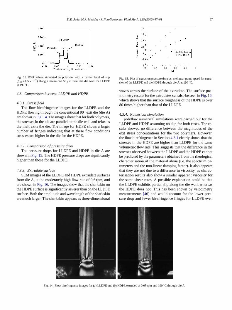
4.3.1. Stress fieldThe flow birefringence images for the LLDPE and the
HDPE flowing through the conventional 90◦ exit die (die A)are shown inFig. 14. The images show that for both polymers,the stresses in the die are parallel to the die wall and relax asthe melt exits the die. The image for HDPE shows a largernumber of fringes indicating that at these flow conditionsstresses are higher in the die for the HDPE.
4.3.2. Comparison of pressure dropThe pressure drops for LLDPE and HDPE in die A are
shown inFig. 15. The HDPE pressure drops are significantlyhigher than those for the LLDPE.
4.3.3. Extrudate surfaceSEM images of the LLDPE and HDPE extrudate surfaces
from die A, at the moderately high flow rate of 0.6 rpm, andare shown inFig. 16. The images show that the sharkskin onthe HDPE surface is significantly severer than on the LLDPEsurface. Both the amplitude and wavelength of the sharkskinare much larger. The sharkskin appears as three-dimensional
Fig. 15. Plot of extrusion pressure drop vs. melt gear pump speed for extru-sion of the LLDPE and the HDPE through die A at 190◦C.
waves across the surface of the extrudate. The surface pro-filometry results for the extrudates can also be seen inFig. 16,which shows that the surface roughness of the HDPE is over80 times higher than that of the LLDPE.
4.3.4. Numerical simulationpolyflow numerical simulations were carried out for the
LLDPE and HDPE assuming no slip for both cases. The re-sults showed no difference between the magnitudes of theexit stress concentrations for the two polymers. However,the flow birefringence in Section4.3.1clearly shows that thestresses in the HDPE are higher than LLDPE for the samevolumetric flow rate. This suggests that the difference in thestresses observed between the LLDPE and the HDPE cannotbe predicted by the parameters obtained from the rheologicalcharacterisation of the material alone (i.e. the spectrum pa-rameters and the non-linear damping factor). It also appearsthat they are not due to a difference in viscosity, as charac-terisation results also show a similar apparent viscosity forthe same shear rates. A possible explanation could be thatthe LLDPE exhibits partial slip along the die wall, whereasthe HDPE does not. This has been shown by velocimetrymeasurements[46] and would account for the lower pres-sure drop and fewer birefringence fringes for LLDPE even
and (b
Fig. 14. Flow birefringence images for (a) LLDPE ) HDPE extruded at 0.05 rpm and 190◦C through die A.
58 D.R. Arda, M.R. Mackley / J. Non-Newtonian Fluid Mech. 126 (2005) 47–61
Fig. 16. SEM images and surface profilometry profiles with Rq values for extrudate surfaces of (a) LLDPE and (b) HDPE extruded at 0.6 rpm and 190◦Cthrough die A (note ordinate scale difference).
though simulations predict that these should be the same forboth polymers.
While the HDPE shows a much higher extrusion pressuredrop and a correspondingly higher number of birefringencefringes for the same volumetric flow rate as the LLDPE, theLLDPE does not exhibit such severe sharkskin even for samepressure drop and number of birefringence fringes. Theremust be something other than the pressure drop and flowbirefringence that accounts for the difference in the sharkskinseverity between the two polymers. The other possible factorsthat could be responsible are discussed in the conclusions tothis paper.
4.4. The effect of a fluoropolymer additive
In this section experiments that were carried out with theHDPE containing 1500 ppm of fluoropolymer as a polymer-processing additive are described. The preparation of the ma-terial is detailed in Section2 of this paper. Rheological char-acterisation experiments showed that G′, G′′ and�* for theHDPE were not modified by addition of the fluoropolymer. Itwas not possible to carry out flow birefringence for the HDPEwith PPA as the fluoropolymer was opaque, and therefore didnot allow penetration of light though the die.
4PPA
t ,t ighert e ofp
4tru-
d
images show that sharkskin is completely eliminated fromthe surface of the HDPE with PPA. There appears to be mi-croscopically small scratch marks at the side of the extrudatetape of the HDPE with PPA. However, this only appears onone side of the tape suggesting it was due to a small protru-sion on the die wall. This extrudate also visually shows whatlook like very small bubbles on the extrudate surface. Thereis no explanation for these at present, but they appeared forall HDPE extrudates with the fluoropolymer as PPA. Surfaceprofilometry results for the HDPE and the HDPE with PPAextruded at 0.6 rpm and 190◦C is also shown inFig. 18. Thesurface roughness of the HDPE extrudate is over 55 timeshigher than the roughness of the HDPE with PPA. The PPAcompletely eliminated sharkskin in the HDPE for all flowrates studied in this paper.
The extrusion pressure drops suggest that the fluoropoly-mer imparts a slip boundary condition along the die wall. Thelevel of slip imparted cannot be obtained using flow velocime-try techniques due to the opaque nature of the fluoropolymeradditive. However, Stewart and Dealy[35] reported that foran optimised system, slip velocity is found to increase with in-
F extru-s
.4.1. Comparison of pressure dropThe pressure drops for pure HDPE and HDPE with
hrough die A at 190◦C are shown inFig. 17. As expectedhe pressure drops for the pure HDPE are significantly hhan those of the HDPE with PPA, indicating the presencartial slip with the addition of the fluoropolymer.
.4.2. Extrudate surfaceSEM images of the pure HDPE and HDPE with PPA ex
ate surfaces from die A at 0.6 rpm are shown inFig. 18. The
ig. 17. Plot of extrusion pressure drop vs. melt gear pump speed forion of the pure HDPE and the HDPE with PPA through die A at 190◦C.
D.R. Arda, M.R. Mackley / J. Non-Newtonian Fluid Mech. 126 (2005) 47–61 59
Fig. 18. SEM images and surface profilometry profiles with Rq values for extrudate surfaces of (a) HDPE and (b) HDPE + PPA extruded at 0.6 rpm and 190◦Cthrough die A (note ordinate scale difference).
creasing fluoropolymer concentration up to about 500 ppm,while for higher fluoropolymer concentrations, the slip ve-locity remains practically constant. The fluoropolymer, thuseliminates the local die exit stress concentrations, and sincethe additive coats all surfaces, there are no additional stressconcentrations elsewhere. Sharkskin is therefore completelyeliminated.
5. Conclusions
Experimental results reported in this paper show that cur-vature of the die exit reduces sharkskin. Optical observationsat the die exit show a delay in the separation point of themelt from the die. This delay in melt/wall separation forcurved exit dies is believed to allow the stresses at the dieexit to relax, and hence reduce the exit melt stress concen-trations. Numerical simulations confirm that with the sepa-rations points experimentally observed for curved exit dies,there is a reduction in the stress concentration at the die exit.Flow birefringence exit fringe concentrations are also quali-tatively observed to reduce with increasing die exit curvature.The number of fringes identified within the main die area, aswell as the pressure drops, are not observed to change with dieexit curvature. These results are consistent with those of Rut-g inf omc avye factt ointa redt ara-t skini
Reducing the roughness of the die surface has been ex-perimentally found to reduce sharkskin. Using three progres-sively smoother dies led to a progressive reduction in themagnitude of sharkskin. This result is consistent with simu-lations of partial slip along the die wall, which show reducedstress concentrations for certain levels of slip. Partial slip isconsistent with the reduced pressure drop and reduced num-ber of birefringence fringes observed for the smoother dies.It is therefore possible that decreasing die surface roughnessreduces sharkskin by allowing partial slip of the melt alongthe die wall, and thereby reducing the magnitude of the stressconcentration at the die exit.
Different polymers show different levels of sharkskin forthe same volumetric flow. The sharkskin on the metalloceneHDPE was found to be significantly severer than on theLLDPE. At a given flow rate, higher pressure drops and morebirefringence fringes were observed for the HDPE. However,this does not completely explain the difference in sharkskinseverity between the two polymers, since for the same pres-sure drop and stress field, the sharkskin exhibited by DowlexLLDPE is still significantly less pronounced. While it is clearthat stress concentrations are a crucial factor for the devel-opment of the sharkskin instability, they cannot be the onlyfactor. Issues that may also be involved include melt strength[12], the level of wall slip[20], the stability of the partialslip boundary condition[25] and the stability of the point ofs
g aflp flu-o ates . Thisi icta long
ers and Mackley[47] who found a reduction in sharkskor a 0.5 mm radiused exit die. A further observation frurved exit dies is that with increased exit curvature, a wxtrudate was obtained, possibly originating from thehat with die exit curvature, the melt/wall separation pt the die exit is less well defined. It could be conjectu
hat at a micron scale, this instability of the melt/wall sepion point can also promote the development of the sharknstability.
eparation of the melt from the die exit[26–28].A well-established way of reducing sharkskin is usin
uoropolymer additive (see, for example[20,22]) and ex-erimental results reported in this paper confirm this. Aropolymer additive was found to dramatically eliminharkskin as well as reduce the extrusion pressure drops consistent with simulations of partial slip, which pred
reduced pressure drop for extrusion with partial slip a

60 D.R. Arda, M.R. Mackley / J. Non-Newtonian Fluid Mech. 126 (2005) 47–61
the die wall. Since the additive is deposited along the wholeof the die surface, as well as the extruder screw and barrel[35], a stress concentration arises only at the die exit. Themagnitude of this stress concentration is lower than that for adie with no slip, since the change in boundary condition fromstick to partial slip is not as abrupt as a change from stick tofull slip, as at the die exit. Additives are thus a very effectivemethod for eliminating sharkskin.
In summary, the results presented in this paper supportthe model that sharkskin instabilities are a consequence oflocal melt stress concentrations. Techniques that reduce themagnitude of the stress concentration, for example die exitcurvature (which allows the exit melt stresses to relax), de-creasing die wall roughness (which is believed to allow apartial wall slip) and introduction of a polymer-processingadditive (which also provides wall slip) have all been found toreduce the severity of the sharkskin instability. However, thefact that the metallocene HDPE shows significantly severersharkskin than the LLDPE for the same extrusion pressuredrop and stress field, indicates that stress concentrations aloneare not the only factor of importance, but other issues such asmelt strength, stability of the partial slip boundary conditionor the melt/wall separation point must also contribute. Fur-ther work is required to determine the exact mechanism bywhich stress concentrations cause sharkskin, whether it is bymelt rupture at or downstream of the die exit, whether it in-v heri
A
oft 3PI).T . B.V thes iningt
R
hE
luid
92)
ess,
: P.logy,logy,
ori-99)
[7] J.J. Benbow, P. Lamb, New aspects of melt fracture, S.P.E. Trans. 3(1963) 7–17.
[8] R.H. Moynihan, D.G. Baird, R. Ramanathan, Additional observationson the surface melt fracture behaviour of LLDPE, J. Non-NewtonianFluid Mech. 36 (1990) 255–263.
[9] F.N. Cogswell, Stretching flow instabilities at the exits of extrusiondies, J. Non-Newtonian Fluid Mech. 2 (1977) 37–47.
[10] P. Beaufils, B. Vergnes, J.F. Agassant, Characterization of the shark-skin defect and its development with the flow conditions, Int. Polym.Proc. 4 (2) (1989) 78–84.
[11] N. El Kissi, J.M. Piau, Adhesion of linear low density polyethylenefor flow regimes with sharkskin, J. Rheol. 38 (5) (1994) 1447–1463.
[12] R.P.G. Rutgers, M.R. Mackley, The correlation of experimentalsurface extrusion instabilities with numerically predicted exit sur-face stress concentrations and melt strength for linear low-densitypolyethylene, J. Rheol. 44 (6) (2000) 1319–1334.
[13] N. Bergem, Visualization studies of polymer melt flow anomaliesin extruders, in: Proceeding of Seventh International Congress onRheology, Gothenberg, 1976, p. 50.
[14] S.J. Kurtz, Die geometry solutions to sharkskin melt fracture in ad-vances in rheology, in: Nineth International Congress on Rheology,Mexico, 1984, pp. 399–407.
[15] Y.W. Inn, R.J. Fischer, M.T. Shaw, Visual observation of develop-ment of sharkskin melt fracture in polybutadiene extrusion, Rheol.Acta 37 (1998) 573–582.
[16] F. Legrand, J.M. Piau, Spatially resolved stress birefringence andflow visualization in the flow instabilities of a polydimethylsiloxaneextruded though a slit die, J. Non-Newtonian Fluid Mech. 77 (1998)123–150.
[17] A.V. Ramamurthy, Wall slip in viscous fluids and influence of ma-
[ 1)
[ ear
[ co-frac-
[ cialol.
[ ofate
[ ar in-sion
[ ofnear
[ bili-
[ en-213.
[ II:97)
[ monian
[ s on317–
[ meltsNon-
olves the wall slip boundary or die exit stability, or whett involves another factor that has not yet been covered.
cknowledgements
The authors would like to thank the EU for the fundinghis project Postpone Polymer Processing Instabilities (hey would also like to thank Prof. J.F. Agassant, Drergnes and Dr. O. Kulikov for useful discussions onubject. Tony Burgess is thanked for his assistance obtahe SEM photographs.
eferences
[1] C.J.S. Petrie, M.M. Denn, Instabilities in polymer processing, AICJ. 22 (2) (1976) 209–236.
[2] M.M. Denn, Issues in viscoelastic fluid mechanics, Annu. Rev. FMech. 22 (1990) 13–34.
[3] R.G. Larson, Instabilities in viscoelastic flow, Rheol. Acta 31 (19213–263.
[4] J.P. Tordella, in: F.R. Eirich (Ed.), Rheology, vol. 5, Academic PrNew York, 1969, p. 57.
[5] M.M. Denn, Surface-induced effects in polymer melt flow, inMoldenaers, R. Keunings (Eds.), Theoretical and Applied Rheoin: Proceeding of the Eleventh International Congress on RheoElsevier, New York, 1992, pp. 45–49.
[6] S.Q. Wang, Molecular transitions at polymer/wall interfaces:gins of flow instabilities and wall slip, Adv. Polym. Sci. 138 (19227–275.
terials of construction, J. Rheol. 30 (2) (1986) 337–357.18] M. Mooney, Explicit formulas for slip and fluidity, J. Rheol. 2 (193
210–222.19] D.S. Kalika, M.M. Denn, Wall slip and extrudate distortion in lin
low-density polyethylene, J. Rheol. 31 (1987) 815–834.20] K.B. Migler, Y. Son, F. Qiao, K. Flynn, Extensional deformation,
hesive failure, and boundary conditions during sharkskin meltture, J. Rheol. 46 (2) (2002) 383–400.
21] X. Yang, H. Ishida, S.Q. Wang, Wall slip and absence of interfaflow instabilities in capillary flow of various polymer melts, J. Rhe42 (1) (1998) 63–80.
22] S.Q. Wang, P.A. Drda, Molecular instabilities in capillary flowpolymer melts: interfacial stick-slip transition, wall slip and extruddistortion, Macromol. Chem. Phys. 198 (1997) 673–701.
23] J.R. Barone, N. Plucktaveesak, S.Q. Wang, Interfacial moleculstability mechanism for sharkskin phenomenon in capillary extruof linear polyethylenes, J. Rheol. 42 (4) (1998) 813–832.
24] S.Q. Wang, P.A. Drda, Y.W. Inn, Exploring molecular originssharkskin, partial slip, and slope change in flow curves of lilow-density polyethylene, J. Rheol. 40 (5) (1996) 875–898.
25] J. Molenaar, R.J. Koopmans, Modeling polymer melt-flow instaties, J. Rheol. 38 (1994) 99–109.
26] P.K. Dhori, J.C. Slattery, Common line motion I: implications oftropy inequality, J. Non-Newtonian Fluid Mech. 71 (1997) 197–
27] P.K. Dhori, A.J. Giacomin, J.C. Slattery, Common line motionsliding plate rheometry, J. Non-Newtonian Fluid Mech. 71 (19215–229.
28] P.K. Dhori, R.S. Jeyaseelan, A.J. Giacomin, J.C. Slattery, Comline motion III: implications in polymer extrusion, J. Non-NewtonFluid Mech. 71 (1997) 231–243.
29] D.D. Joseph, Y.J. Liu, Letter to the editor: steep wave frontextrudates of polymer melts and solutions, J. Rheol. 40 (1996)319.
30] D.D. Joseph, Steep wave fronts on extrudates of polymerand solutions: lubrication layers and boundary lubrication, J.Newtonian Fluid Mech. 70 (1997) 187–203.

D.R. Arda, M.R. Mackley / J. Non-Newtonian Fluid Mech. 126 (2005) 47–61 61
[31] J. Barone, S.Q. Wang, Flow birefringence study of sharkskin andstress relaxation in polybutadiene melts, Rheol. Acta 38 (1999)404–414.
[32] B. Tremblay, Sharkskin defects of polymer melts: the role of cohe-sion and adhesion, J. Rheol. 35 (6) (1991) 985–998.
[33] D.E. Priester, C.W. Stewart, New Processing Additives for Poly-olefins Minimize Formulation Interactions, SPE ANTEC, Detroit,1992, pp. 2024–2028.
[34] C.W. Stewart, Wall slip in the extrusion of linear polyolefins, J.Rheol. 37 (3) (1993) 499–513.
[35] C.W. Stewart, J.M. Dealy, Technical note: new information on themechanism of action of the adhesion promoter reported in wall slipof molten high density polyethylene, J. Rheol. 35 (1991) 497;C.W. Stewart, J.M. Dealy, Technical note: new information on themechanism of action of the adhesion promoter reported in wallslip of molten high density polyethylene, J. Rheol. 36 (5) (1992)967–969.
[36] F. Yip, S.G. Hatzikiriakos, T.M. Clere, A new processing aid forthe extrusion of polyolefins, J. Vinyl Addit. Technol. 6 (2) (2000)113–118.
[37] E.E. Rosenbaum, S.K. Randa, S.G. Hatzikiriakos, C.W. Stewart, D.L.Henry, M. Buckmaster, Boron nitride as a processing aid for theextrusion of polyolefins and fluoropolymers, Polym. Eng. Sci. 40(1) (2000) 179–190.
[38] J.M. Piau, N. El Kissi, F. Toussaint, A. Mezghani, Distortions ofpolymer melt extrudates and their elimination using slippery sur-faces, Rheol. Acta 34 (1995) 40–57.
[39] S.G. Hatzikiriakos, J.M. Dealy, Effects of interfacial conditions onwall slip and sharkskin melt fracture of HDPE, Int. Pol. Proc. 8(1993) 30–35.
[40] O. Kulikov, K. Hornung, A simple way to suppress sur-face defects in the processing of polyethylene, in: Pro-ceedings of Twelfth International Conference of Deformation,Yield and Fracture of Polymers, Cambridge, 2003, pp. 411–414.
[41] D.R. Arda, The sharkskin extrusion instability and its min-imisation in polyethylene processing, Ph.D. Thesis, Cambridge,2003.
[42] G.G. Lipscomb, R. Keunings, M.M. Denn, Implications of boundarysingularities in complex geometries, J. Non-Newtonian Fluid Mech.24 (1) (1987) 85–96.
[43] M. Renardy, Current issues in non-newtonian flows: a mathemat-ical perspective, J. Non-Newtonian Fluid Mech. 90 (2–3) (2000)243–259.
[44] C. Venet, B. Vergnes, Experimental characterization of sharkskin inpolyethylenes, J. Rheol. 41 (4) (1997) 873–892.
[45] D.R. Arda, M.R. Mackley, Sharkskin instabilities and the effect ofslip from gas-assisted extrusion, Submitted to Rheol. Acta, March2004.
[46] H. Munstedt, A. Merten, A personal communication, 2004.[47] R.P.G. Rutgers, M.R. Mackley, The effect of channel geometry and
wall boundary conditions on the formation of extrusion surface in-stabilities for LLDPE, J. Non-Newtonian Fluid Mech. 98 (2001)185–199.