the experimental and theoretical evaluation of a …
TRANSCRIPT
Ocean Engng, Vol. 10, No 5, pp. 325-345, 1983. 0029-8018/83 $3.00+.00 Printed in Great Britain. Pergamon Press Ltd.
THE EXPERIMENTAL AND THEORETICAL EVALUATION OF A TWIN-FLAP WAVE-ENERGY ABSORBING DEVICE
ROBERT M. SCHER,* ARMIN W. TROESCH* and GuoJuN ZHou' l *Department of Naval Architecture and Marine Engineering, The University of Michigan, Ann Arbor, MI
48109, U.S.A. and *Visiting Research Scientist, The University of Michigan, China Ship Scientific Research Center, China
AbstraetmA series of model experiments with a twin-flap wave-energy absorbing device is described, and the results compared with numerical predictions based on theoretical work reported by Srokosz and Evans (1979). Measurements were made of absorption efficiency, flap motion responses, and total flap forces (mooring forces), all with the supporting structure held fixed, with normal wave encounter. Both 2-D and finite-length flap experiments were conducted.
Generally, fair agreement was obtained between theory and experiments with regard to efficiency vs wavenumber and applied damping coefficient was generally matched by apparent from these experiments. Maximum efficiencies approaching 100% (as predicted analytically) were confirmed by experiments. Further, the predicted behavior of curves of efficiency vs wave number and applied damping coefficient was generally matched by experimental results.
Results for flap motion responses and forces showed good agreement with theory. Some basic conclusions are drawn with regard to practical design and economic considerations
for a twin-flap power generating system.
I N T R O D U C T I O N
WITHIN the last several years there has been a significant amount of research activity in the field of energy recovery f rom ocean waves. In several nations, notably Japan and the Uni ted Kingdom, these efforts have extended to the construction and testing of large-scale prototypes , some of them capable of electrical-power generat ion on the order of 100 kW or more (see, for example , Panicker, 1976; Proc. Syrup. Wave Tidal Energy, 1979, 1981).
Because of the nature of water waves, there is an almost unlimited number of possible device configurations for convert ing the mot ion of water into mechanical response and ult imately into useful work, as an inspection of patent claims will show. This repor t describes a series of model exper iments with a twin-flap wave-energy absorbing device, pe r fo rmed during 1981 and early 1982 in the towing tank of the Depa r tmen t of Naval Archi tecture and Marine Engineering at the University of Michigan. In addition to model tests an analytical compute r p rogram, based on earlier work repor ted by Srokosz and Evans (1979), was adapted to the Universi ty 's compute r system, with certain modif icat ions to facili tate direct compar isons be tween exper imenta l results and theoretical predictions. The analytical results, therefore , are based on linear wave, ideal-fluid theory. In addition, the so-called "far-field" approximat ion, due to Ohkusu (1974) is made implicitly.
325

326 ROBERT M. SCHER et al.
EXPERIMENTAL APPARATUS
The twin-flap device consists of two independent parallel flaps, partially immersed and supported so as to allow roll or sway motion of the flaps in response to incident waves. The motion of each flap is damped by an external power takeoff system. For the purposes of small model experiments it was considered essential that each power takeoff consist of a single hydraulic cylinder; otherwise, the required instrumentation would have become too complex.
A principal objective of these model tests was to obtain a direct comparison with the theoretical results by Srokosz and Evans (1979), which was based strictly on two-dimensional flow. Accordingly, two-dimensional tests were conducted initially, using a flap width that spanned the entire tank, with the smallest possible clearances at the sides. The flap widths were 6.43 m, with a maximum flap draft of about 0.38 m. In a subsequent series of experiments, the flaps were modified to permit the modeling of end effects. It should be mentioned here, however, that at no time was the model intended to represent any particular "full-scale" device. Thus, no particular scale ratio was implied by the choice of model dimensions. Figure 1 shows a cross-section of one of the flaps, with its supporting guides.
Wave measurements
In most experiments in waves, a single measurement of the incident wave is obtained with a wire or sonic wave probe, located in such a position that the amplitude of the measured wave is presumably unaffected by the presence of the model. In experiments with the flap device, however, the presence of a reflected wave component made the identification of the incident wave amplitude considerably more difficult.
In the majority of the experimental runs described here, the following procedure was employed to resolve the various wave components:
iiIiiitli,,ll/,.,./,
Linear baLL bushings ~
~"~.~ Guide rod
I ...................... ~~,~/j./" ~'on~;~,;'s'.;L~ .......... '""
/ WaterLine
FIG. la. Elevation showing flap support and side-guide arrangement.

Twin-flap wave-energy device
U - ~ ' " ~'~,,'~J
'1 II II
FIG. lb. Spring arrangement (elevation on tank centerline).
327
FLuid reservoir
Damping '-11"11"- control / 1 1 / vo~. \ tllllT
Check valve
~ ¥o .~o 0o~ ~ "
L
Load cett
: I I ,
FIG. lc. Schematic of power takeoff and mechanical power measurement instrumentation.
On the side toward the wavemaker , as shown in Fig. 2, the wave system was assumed to consist of two components: an incident wave, travelling in the positive x-direction, and a "'reflected" wave, travelling in the negative x-direction. In order to resolve the amplitudes of these two waves, two wave probes were required on the wave-ward side of

328 ROBERT M. SCHER et al.
E
l X
IA/D Converter I - ' ~ -~
WaterOne
! _L
FIG. 2. Schematic of experimental instrumentation and twin-flap device geometry.
• the model. The signals from these two probes, after being Fourier transformed, were combined to give the resulting amplitudes of the incident and reflected waves. Two wire probes, located about 3.6 m from the flap device, and separated by about 0.75 m, were used for the incident and reflected wave measurements.
On the side away from the wavemaker, only a wave travelling in the positive x-direction could exist. Therefore, a single wave probe was used to measure the transmitted wave.
In later experiments, investigating flap end effects, it became necessary to evaluate the incident wave amplitude indirectly, since it was observed that wave amplitudes varied considerably at different locations across the width of the tank. For this reason, calibration experiments were performed on the wavemaker itself, in the absence of the

Twin-flap wave-energy device 329
flaps, relating the amplitude of the wavemaker's displacement to the amplitude of the incident wave at the location of the model flap device. These tests were performed at two frequencies, and permitted the incident wave amplitude to be inferred from the motion of the wavemaker. Over a number of runs, the repeatability of the wave amplitudes was found to be within 1-2%, and therefore an acceptable degree of accuracy was expected. A sonic wave probe was used to measure the displacement of the wavemaker in these later experiments.
Flap displacement measurements
Records of the motion of the two flaps were obtained by linear potentiometers, consisting of a spring-loaded reel and cable system connected to a normal rotary potentiometer. The body of the instrument was installed on a fixed support, while the free end of the cable was attached to a fitting on the flap, near the centerline. The output from these two "yo-yo" potentiometers was then proportional to the position of the flaps, and could be processed in much the same manner as wave records.
Power takeoff force measurements
In order to measure the power outpu t and to evaluate the damping coefficients on a given run, force measurements were required in conjunction with flap motion records. These forces were measured between the hydraulic cylinders and fixed supports attached to the carriage, using standard 4500-N capacity load cells.
Data recording and processing
The output from instruments normally consisted of 7 channels as shown in Fig. 2: three wave probes, two yo-yo potentiometers, and two load cells. These signals were converted from analog to digital form on a Tektronix 4052 microcomputer, and all subsequent processing was performed on the digitized records, each record consisting of 1024 sample points. To begin the analysis, each signal was tapered, using a Harming window, then Fourier transformed, and a spectral peak was found on one of the records (usually the lead wave probe). Since the testing took place in nominally sinusoidal waves, the spectral decomposition of the data was quite narrow-banded. In general, the only significant spectral densities on any channel were to be found at the peak frequency or the frequency components immediately adjacent to it. For this reason, printed output was confined to just a few of the frequency components around the peak, usually five components, with the most significant results normally to be found at the peak frequency itself.
The following experimental output requires definition:
Wave efficiency. The efficiency of the device was measured from data on incident, reflected, and transmitted wave amplitudes, without recourse to load-cell or flap-motion results. Thus, this definition of efficiency also includes energy extracted by extraneous damping components due to friction in the guides, etc., which were not directly measured through the load cells. Specifically, at any given frequency, the wave efficiency was defined as
+
"q., = 1 ~t 2

330 ROBERT M. SCnER et al.
where .~t, ~R, and ~r are the incident, reflected, and transmitted wave amplitudes, respectively. This definition of efficiency has been derived by Srokarz and Evans, and elsewhere.
Reflection and transmission coefficients. For comparison with theoretical predictions, the reflected and transmitted wave amplitudes were simply divided by the amplitude of the incident wave, forming the coefficients
R = {R/{t, T = ~4g, i
Flap-motion response amplitude operators. For each flap, the amplitude of the motion was divided by the incident wave amplitude, giving the dimensionless responses
RAOI = A1/{,, RA02 ---- A 2 / ~ I ,
where A1 and A2 are the flap motion amplitudes.
Mechanical efficiency. The efficiency in terms of actual power output from the hydraulic dampers and power contained in the 2-D incident wave was evaluated at each output frequency as follows: power output from each power takeoff was calculated as
Po~t = "rrFXf
where F is the amplitude of the load cell force record, X is the amplitude of the flap motion as measured by the yo-yo potentiometer, andf is the frequency of the component (in Hz). These two power outputs were independent, and were therefore added to give a total mechanical power output. The power in an incident deep-water sinusoidal wavefront of width w and frequency f is given by linear theory as
1 Pin = 8"rr- pg2~/2 w/f
where p is the density of water, g the acceleration of gravity. Thus, the mechanical efficiency is given by
Pore = 8TI,2 fZ(F,X, + FzX2) 'l'~mech -- Pin pgew ~12
where the subscripts 1 and 2 refer to the force and motion amplitudes of the two flaps, respectively. It should be noted that this form of evaluating the efficiency neglects any power losses through guide friction. The definition and calculation of mechanical

Twin-flap wave-energy device 331
efficiency allowed an alternative check on the wave efficiency previously mentioned, using measurements needed to evaluate the effective damping coefficients (see below). In those experiments where both efficiencies were calculated, it was found that the wave efficiency was generally more reliable.
Effective damping coefficients. For the purposes of comparison with theorectical predictions it was necessary to estimate the damping coefficients provided by the hydraulic power takeoffs. These were simply calculated as
D1 -- 2 ~ f X l ' D2 - 2~fX2
for the two flaps. Note that this method of calculating the external damping also excludes any friction in the side guides, etc. Thus, this estimate of damping is by definition a lower bound on the actual value.
Mooring force. For the sway geometry, the total force acting on the supporting structure was assumed to include the damper forces, whose magnitudes and phases were directly measured from the load cell records, and the spring forces. Although the forces at the spring brackets were not measured directly, the magnitude and phase of the flap displacements were available as measured by the yo-yo potentiometers. Thus, the magnitudes and phases of the spring forces were obtained from the displacements, using a total spring constant measured during the calibration process, as will be discussed subsequently. The spring and damper forces for each flap were added vectorially in the sense of a phase diagram. The sum of these forces for both flaps is referred to as the mooring force for the twin-flap array, Fmoor. For the purpose of data presentation, the nondimensional mooring force coefficient is defined as
Cmoor t Fmoor ( 4/Tr )pgaw~z
where a is the flap draft, w is the flap width, and I / i s the incident wave amplitude.
Experimental results
The experimental results are shown together with the theoretical calculations in Figs 3-18. The experimental data points are denoted by either "o" or "o"s. The corresponding theory is shown by solid lines. For ease of comparing theory with experiment, it was intended that both PTO's have the same damping coefficient. However, the damping coefficients D1 and D2 were controllable only within a very rough tolerance before each run. Therefore, on most runs it was found that the values of D1 and D2 were dissimilar to an extent, usually by less than 1%, but occasionally by as much as 15%. For this reason, the comparison of experimental points with theoretical curves should be regarded as indicating broad trends rather than detailed magnitudes.
332 ROBERT M. SCrIER et al.
3.5
3.0
2 5 / o o o2oo 2.0 DI = /72 = 6.0
1.5
~ O - 0 . 0 0.5
D-3.0 I I I f I I p - ' ~ D=6 .0
0,2 0.4. 0.6 0.8 1.0 1.2 1.4 I 6
Ira
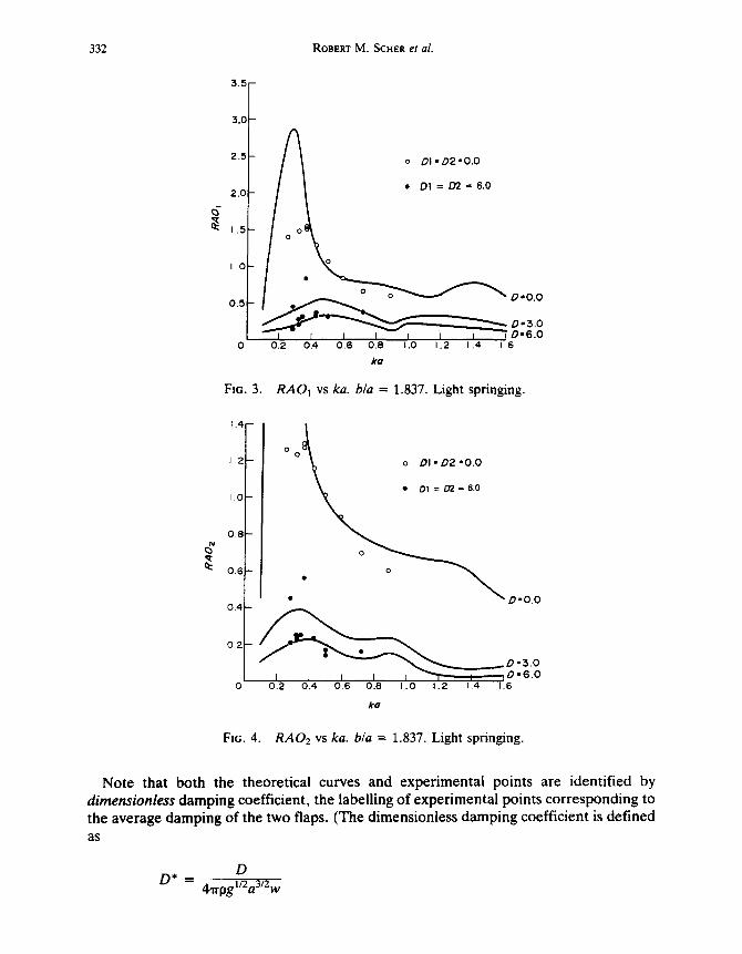
FIG. 3. RA01 v s ka. b/a = 1 . 8 3 7 . Light springing.
1.4
1.2
I 0
0.8
0.6
0.4
0.2
o o ~ o DI'D2=O.O
• • o o " O'O.O
Ira
FIG. 4. R A 0 2 vs ka. b/a = 1.837. Light springing.
Note that both the theoretical curves and experimental points are identified by d i m e n s i o n l e s s damping coefficient, the labelling of experimental points corresponding to the average damping of the two flaps. (The dimensionless damping coefficient is defined a s
D D* - 4,trpgl/2a3/2w

Twin- f l ap w a v e - e n e r g y dev ice 333
0 . 6
==
' ; 0.4
I . O ~
o D I = D 2 " 0 . 0
• DI = D 2 - - - 6 . 0 0 , 8
- | o
oQ
• O - 3 . O
o L / o v • D = 6.0
0 . 2 / / o
• o
0 0 . 2 ~).4 0 . 6 0 . 8 1.0 1.2 1.4 ! .8
k ¢
FIG. 5. Wave efficiency vs ka. b/a = 1.837. Light springing.
"E
e-
,= n.-
1 .0
0 . 8
0 . 6
0 .4
0 .2
o D I = D 2 " 0 . 0
• D1 = 02 = 6.0 / o.o.o
o o
I 0.2 ~).4 0.6 0.8 1.01.2 1.4 1.6
#O
FIG. 6. Reflection coefficient vs ka. b/a = 1.837. Light springing.
where D is the dimensional damping coefficient, a the flap draft, and w the flap width.) The spring constants were set at a value of approximately 7000 N/M for each flap. This
is identified in the figures as "Light springing". Figures 3--8, respectively, show RAOI, RAO2, ~lw, R, T, and Cmoor, all plotted vs
nondimensional wavenumber ka for a particular model geometry and springing. These figures show generally good agreement in motion RAO's, although wave efficiencies are

3 3 4 ROBERT M . SCHER et al.
1.0 -- o o o o - - ~
0 . 8 o " L \ ? ! o o.oo
d 1 J I I I I J 0 0.2 04 06 0.8 1.0 1.2 1.4 1.6
ka
Transmission coefficient vs ka. b/a = 1.837. Light springing.
0 . 6
~ 0 . 4
c
k-
0 . 2
FIG. 7.
to
o~
E ~o
FIG. 8.
5.0
40
3.0
2.0
1,0
o DI= D2=O.0
• Ol = D 2 - 6 . 0
" ~ D ' 6 . 0 I / ~ o - 3 . o
_ o . o . o
I I I ~ I I I I 0.2 0.4 0.6 0.8 1.0 1.2 1.4 16
ka
Mooring force coefficient vs ka. b/a = 1.837. Light springing.
higher than theoretical predictions, particularly at light damping. Apparent ly, this reflects frictional losses, which were not measured by the load cells on the power takeoffs.
In Figs 9-14, the flap motion RAO's , wave efficiency, reflection and transmission coefficients, and mooring force coefficient are plotted on a base of dimensionless damping coefficient, rather than nondimensionai wavenumber ka.

Twin-flap wave-energy device 335
3.5
FIG. 9.
FIG. 10.
RAO] vs
3.0
2,5
2.0
1.5
o k o ' 0 . 6 7 2
• ka = 1.051
0.~ = k o • 0 . 6 7 2 k o = I .051
0 1.0 2.0 3.0 4.0 5.0 6.0
Domping coefficient
dimensionless damping coefficient, b/a = 0.880. Light springing.
4 f 1.2
1.0
0.8'
0 .6
0 .4
0.2
0
o k o . 0 . 6 7 2
• #o=1.052
I ra =0 .672
k o = 1.051
1.0 2.0 3.0 4 0 5.0 6.0
Dornping coefficient
R A O 2 vs dimensionless damping coefficient, b/a = 0.880. Light springing.
The results in Figs 9-14 were plotted for two wavenumbers, ka = 0.672 and 1.051. Agreement with theory is generally good, however, there remains a fairly consistent divergence from theory on the wave efficiency, with the experimental measurements generally higher than theory predicts. This discrepancy was more notable for the shorter waves, ka = 1.051.
Figures 15-28 show the results of two setup geometries, namely, a full-width flap and a

336 ROBERT M. SCHER et al.
FIG. 11.
1.0
• g O
0 0 0.8
• ~ #a=0.672
0.6 #o = I .051
0.4i
0.2: " ~
0 1.0 2.0 3.0 4.0 5.0 6.0
D a m p i n 9 c o e f f i c i e n t
Wave efficiency vs dimensionless damping coefficient, b/a = 0.880. Light springing.
1.0
,.a
..?,= "$
0.81
O.E
0.4
0.2
o k a = 0.672
• ka =1 ,051 ka =1.051
=, o ka = 0.672 • 0
I t I ~ I I I .0 2 . 0 3 . 0 4 . 0 5 . 0 6 . 0
D a m p i n g c o e f f i c i e n t
FIG. 12. Reflection coefficient vs dimensionless damping coefficient, b/a = 0 . 8 8 0 . Light springing.
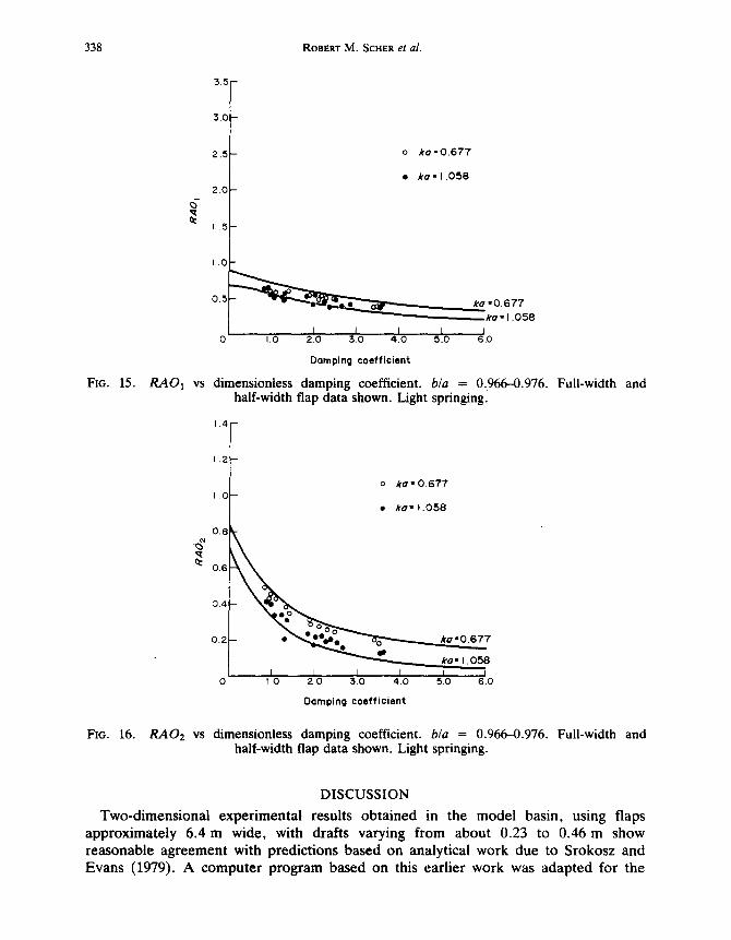
half-width flap with spring constants roughly halved and approximately the same range of nondimensional damping coefficients. The data is plotted versus damping. The results for the flap motion RAO's agree well with theory, and there is little difference between the two flap widths. In fact, the variation in motion RAO's for the two widths was within experimental scatter, so the two sets of points are not differentiated in Figs 15 and 16. With regard to mechanical efficiency (wave efficiency was not measured in the 3-D

T w i n - f l a p w a v e - e n e r g y d e v i c e 337
I.O
FIG. 13.
"• o f ro = 0 . 6 7 2
° . , "
~_ ko = 0 . 6 7 2
0 .2 - .. f • eo~~~o o . • • 1"0"511
0 1.0 2 .0 3 . 0 4 . 0 .5.0 6 .0
Damping coefficient.
Transmission coefficient vs dimensionless damping coefficient, bla = 0.880. Light springing.
3 . 5 -
3 . 0
'~ 2 . 5 .o .o
,~ 2 .0 o
1.5
g "o ~ - I. 0 =E
0 .5
o ka l 0 . 6 7 7
• k o = 1.058
o °~lP k a = O ' 6 T ' / ' 8 ~ ~ a ~l̀'̀---,',"̀'-'-'-~'~ e _ k a = 1 . 0 5 8
0
f i I I r J 1.0 2 .0 $ .0 4 .0 5 .0 C.O
Domping coefficient
FIG. 14. Mooring force coefficient vs dimensionless damping coefficient, b/a -- 0.880. Light springing.
experiments, for reasons already given) the results again show a consistent divergence from theory, with experimental points nearly always higher than theoretical predictions. For the longer wavelength, ka = 0.68, the two geometries yielded essentially similar results; for the shorter wavelength, significantly lower efficiences occurred with the shortened flap, as shown in Fig. 17. Mooring force coefficients show fair agreement with theory, with experiments generally somewhat higher than predictions.
338 ROBERT M. SCHER et al.
3.5-
FIG. 15.
FIG. 16.
R A O l vs
5.0
2.~
2.0
1.5
1.0
o k a • 0 . 6 7 7
• k e • 1.0.58
0.5 k~~.~.,~,~~ =0.677 # o • 1 . 0 5 8
I 0 i.O 2.0 3.0 4.0 5.0 6.0
D a m p i n g c o e f f i c i e n t
dimensionless damping coefficient, b/a = 0.966--0.976. Full-width and half-width flap data shown. Light springingl
o ka= 0.677
• /re= 1.058
•g~7 #a = 1.058
f I I I I I l O 20 3.0 4.0 5.0 6.0
4 I t.2
1.0
0.8
0.6
0.4
0.2
0
D a m p i n g c o e f f i c i e n t
R A O 2 v s dimensionless damping coefficient, b/a = 0.966--0.976. Full-width and half-width flap data shown. Light springing.
DISCUSSION
Two-dimensional experimental results obtained in the model basin, using flaps approximately 6.4 m wide, with drafts varying from about 0.23 to 0.46 m show reasonable agreement with predictions based on analytical work due to Srokosz and Evans (1979). A computer program based on this earlier work was adapted for the

Twin-flap wave-energy device 339
1,0 e o % ~
I ~ "°° %° o al . ; . "
• i ,o ,o.o.6,
0.21/F! • • k o " 1.058
/ ! I I I I I J
0 1.0 2.0 3.0 4.0 5.0 6.0
Domping coeff icient
FIG. 17. Mechanical efficiency vs dimensionless damping coefficient, b/a = 0.966-0.976. Full-width and half-width flap data shown (half-width data points encircled). Light springing.
3 . 5 -
FIG. 18.
0
g g
3.0
2.5
2.0
1.5
1.0
0
o ko • 0.672
• ha= 1.051
o _ _ k a . 0 . 6 7 2
~ k o • 1.051
I I J I I I I.G 2 .0 3 0 4 .0 5.0 6 .0
Damping c o e f f i c i e n t
Mooring force coefficient vs dimensionless damping coefficient, b/a = 0.966--0.976. Full-width and half-width flap data shown. Light springing.
Michigan computer system, and slightly modified to permit the prediction of performance for flaps moving in pure sway (which was the arrangement chosen for the experimental apparatus) as well as roll. This program was then used to facilitate the comparison between theory and experimental results.
Some qualitative conclusions based on this comparison are as follows:
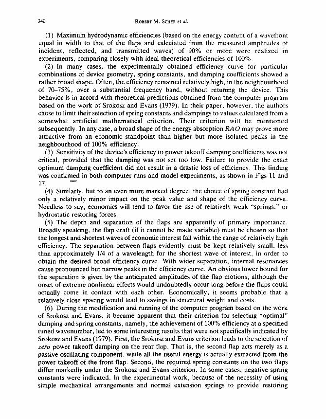
340 ROBERT M. SCHER et al.
(1) Maximum hydrodynamic efficiencies (based on the energy content of a wavefront equal in width to that of the flaps and calculated from the measured amplitudes of incident, reflected, and transmitted waves) of 90% or more were realized in experiments, comparing closely with ideal theoretical efficiencies of 100%.
(2) In many cases, the experimentally obtained efficiency curve for particular combinations of device geometry, spring constants, and damping coefficients showed a rather broad shape. Often, the efficiency remained relatively high, in the neighbourhood of 70-75%, over a substantial frequency band, without retuning the device. This behavior is in accord with theoretical predictions obtained from the computer program based on the work of Srokosz and Evans (1979). In their paper, however, the authors chose to limit their selection of spring constants and dampings to values calculated from a somewhat artificial mathematical criterion. Their criterion will be mentioned subsequently. In any case, a broad shape of the energy absorption R A O may prove more attractive from an economic standpoint than higher but more isolated peaks in the neighbourhood of 100% efficiency.
(3) Sensitivity of the device's efficiency to power takeoff damping coefficients was not critical, provided that the damping was not set too low. Failure to provide the exact optimum damping coefficient did not result in a drastic loss of efficiency. This finding was confirmed in both computer runs and model experiments, as shown in Figs 11 and 17. "-"
(4) Similarly, but to an even more marked degree, the choice of spring constant had only a relatively minor impact on the peak value and shape of the efficiency curve. Needless to say, economics will tend to favor the use of relatively weak "springs," or hydrostatic restoring forces.
(5) The depth and separation of the flaps are apparently of primary importance. Broadly speaking, the flap draft (if it cannot be made variable) must be chosen so that the longest and shortest waves of economic interest fall within the range of relatively high efficiency. The separation between flaps evidently must be kept relatively small, less than approximately 1/4 of a wavelength for the shortest wave of interest, in order to obtain the desired broad efficiency curve. With wider separation, internal resonances cause pronounced but narrow peaks in the efficiency curve. An obvious lower bound for the separation is given by the anticipated amplitudes of the flap motions, although the onset of extreme nonlinear effects would undoubtedly occur long before the flaps could actually come in contact with each other. Economically, it seems probable that a relatively close spacing would lead to savings in structural weight and costs.
(6) During the modification and running of the computer program based on the work of Srokosz and Evans, it became apparent that their criterion for selecting "optimal" damping and spring constants, namely, the achievement of 100% efficiency at a specified tuned wavenumber, led to some interesting results that were not specifically indicated by Srokosz and Evans (1979). First, the Srokosz and Evans criterion leads to the selection of zero power takeoff damping on the rear flap. That is, the second flap acts merely as a passive oscillating component, while all the useful energy is actually extracted from the power takeoff of the front flap. Second, the required spring constants on the two flaps differ markedly under the Srokosz and Evans criterion. In some cases, negative spring constants were indicated. In the experimental work, because of the necessity of using simple mechanical arrangements and normal extension springs to provide restoring

Twin-flap wave-energy device 341
force, only positive spring constants were studied. However, both of these results may be of economic or practical design significance.
(7) Accordingly, it seems that future models of the twin-flap device should be of the rolling type, with a pivot point located at or below the bottom edge of the flap, rather than the sway linear-motion type used in the experiments up to this point. In fact, the linear type was adopted because it simplified the springing arrangements and the measurement of certain forces and displacements, but it also proved to have its drawbacks in terms of friction and alignment problems.
A rolling arrangement, if used (in full scale) with suitable buoyancy tanks fixed to the flaps, would be able to provide hydrostatic restoring forces that would take the place of mechanical springing. At full scale, it is clear that the use of hydrostatic restoring forces is essential. In addition, the partial or complete flooding of these submerged tanks could be used to produce negative "spring constants" if desired. Apart from this, a pivoted rolling flap arrangement might produce some structural and mechanical simplifications.
(8) The common use of the two-dimensional definition of efficiency for wave-power absorbers (namely, the extracted power divided by the average power contained in an extent of incident wavefront equal to the width of the device) is arbitrary, although it offers a convenient means of comparing systems of various sizes, as in model testing. By contrast, the concept of "capture width," which is simply the length of wavefront containing incident power equal to the extracted power, is of more significance, particularly in the case of oblique encounter, finite width arrays, or "point" absorbers. However, it is not a dimensionless quantity. Nondimensionalizing by the array length or width results in a complete analogy with the two-dimensional efficiency, which is useful for scaling model results, but not for comparing alternative systems. Clearly, the actual measure of merit for competing wavepower systems is an economic one, and total system costs are not solely dependent on array length, but on other factors as well. These must include structural weight, complexity, vertical and horizontal mooring or supporting forces, and perhaps most importantly, the mechanical arrangements involved in power conversion.
Several technical issues arising from a consideration of these theoretical and experimental results are discussed at greater length in the following sections.
Effects of finite flap length on two-dimensional efficiency Apart from the issue of efficiency in oblique seas, which has not yet been investigated
in detail, the question of end effects arises even with normal wave encounter. For flaps of finite length the diffraction of the incident wave can, in principle at least, lead to either increased or decreased values of the 2-D efficiency, relative to the results of a purely two-dimensional analysis. Thus, for example, a so-called "point absorber" can in fact intercept wave energy from a width of wave-front that is essentially unrelated to the device's projected width. By the same token, however, it is possible that the incident wave may be diffracted around the array, leading to a reduction in the apparent 2-D efficiency.
In the limit of short wavelength, that is, with a wavelength that is substantially shorter than the width of the array, the hydrodynamic solution is essentially two-dimensional everywhere except in the immediate neighborhood of the ends. Thus, for short waves,

342 ROBERT M. SCHER et al.
the amount of energy extracted by the device should be directly proportional to the width of the array, and the 2-D efficiency will not vary significantly with flap width. For long waves, where the wavelength may greatly exceed the width of the array, the diffraction of the incident wave due to finite array length must be considered more carefully in order to predict the influence on efficiency.
In our model tests, finite array widths were studied as follows: the outboard quarter lengths of the flaps were removed, leaving a flap width equal to one-half the tank width. Thus, for incident waves having a given total energy, a constant 2-D efficiency would result in an extracted power equal to one-half of the energy extracted using a full-width flap.
Two incident wavelengths were examined: the longer wave had a wavelength approximately equal to the width of the shortened flap, while the shorter wavelength was on the order of half of the flap width. It would have been desirable to conduct similar tests with wavelengths substantially longer than the flap width, and with extremely short waves, but this was not possible due to limitations of the wavemaker and the experimental apparatus.
The results of these experiments deserve some comment. For the shorter wavelength the measured 2-D efficiency declined significantly from the full-width flap to the shortened flap setup, noting that the spring constants and damping coefficients were also halved in order to yield equivalent stiffness and damping per unit of flap width. This is not in keeping with the expected (and theoretically correct) two-dimensional nature of the solution in the limit of short waves. Apparently a wavelength on the order of half the flap length may not be construed as representing the limit of short waves.
For the longer wave (a wavelength on the order of the flap width) a very slight increase in the measured 2-D efficiency was noted. Again, it must be stated that this behavior may or may not continue into the limit of very long waves. The answer to this question must await either further experimental results or a detailed three-dimensional analytical model.
It should also be mentioned here that the test configuration with the half-width flap does not correspond exactly to the situation of a single isolated flap segment in the presence of a long-crested incident wave. Due to the finite width of the tank itself, the actual experiment corresponds rather to an infinite array of interrupted flaps, with the space between adjacent segments equal to the widths of the segments. In the limit of short wavelengths, the presence of these "images" should have no effect on the results. The question then becomes this: up to what wavelength can the short-wave solution be regarded as reasonably valid for practical purposes?
In a sense, the fact that the 2-D efficiency remained almost constant even for a wavelength on the order of a flap width suggests that the two-dimensional behavior of the solution extends up to relatively long waves without giving large errors. Certainly, for flap segments separated by a wavelength the interaction between adjacent segments might be expected to be small, at least on an intuitive level. A further resolution of this question, which really involves the behavior of the system in the limit of very long waves, is not possible on the basis of the experimental work done so far.
Mooring forces With regard to mooring forces, the agreement between the experimental results and
the theoretical predictions is in general quite good.
Twin-flap wave-energy device 343
It has been noted that the theory predicts that for certain geometries the mooting force vanishes at a certain wavelength, and this has been verified by experiment (as in Fig. 8). However, the geometries involved seem to be those with relatively large b/a, which in general are not those associated with high, broad efficiency curves. In addition, the wavenumbers at which the mooring forces are minimized also seem to correspond to dips in the efficiency curves.
In itself, this behavior is not necessarily undesirable. From a practical standpoint, the need to minimize mooring forces occurs in extreme seastates, which may also be so energetic that the generating capacity of the power takeoff device cannot han~lle the entire input with the absorber working at high efficiency. Thus, a balanced design would recognize the fact that in seastates where mooring forces must be minimized, the generators would be working near capacity even with a reduced absorption efficiency.
A typical value of the mooting force coefficient near maximum efficiency (say for the b/a = 0.88 configuration, at ka = 0.8) is about 1.2. For a hypothetical full scale device with a draft of 7.3 m, operating in regular waves of 1 m amplitude, this coefficient corresponds to a mooring force amplitude of 143,000 N/m of array width. Clearly, such forces must be considered as a major design problem; any form of mooring in deep water would allow at least some motion of the supporting structure under these forces. Presumably, such motions would result in some loss of efficiency, if the experience of other experimenters (for example, Carmichael, 1978) is any guide.
For this reason, it now seems that large mooring forces may dictate a return to the idea of a fixed rather than a floating structure. To a first approximation, mooring force is linear in wave height. While a 2-m wave height might represent a perfectly reasonable design seastate insofar as energy considerations are concerned, the mooring forces will become extremely large in seastates above design. Note also that in a typical random sea with a 2-m significant height, much higher waves exist.
In any case, the ability to reduce mooring forces by suitable tunings (as can be done for certain array geometries) now seems to be a very desirable thing for full scale applications. In fact, this ability may be worth some substantial compromises in terms of efficiency.
It should be mentioned, though, that the mooring forces measured in our experiments, and predicted by the current version of the analytical program, include not only the damping reaction forces but also the spring forces. With the use of hydrostatic restoring forces the actual values of the mooring force amplitudes will change, although the extent of the saving cannot be predicted at this point. Without question this point should be investigated in greater detail in future work.
Economic concerns
The principal economic issues to be resolved may be placed in a few distinct categories:
(1) Scaling. As shown above, for a particular seastate, the choice of a geometry (b/a, primarily) implies that a certain value of the flap draft must be selected in order to place the RAO curve in a suitable part of the spectrum for maximum energy extraction. Presumably, since a given geographic location is characterized by a distribution of seastates (rather than a unique spectrum) the actual scale of the device must be selected as a compromise. The nature of this compromise is likely to be critical, but the fact that a given flap draft (in connection with a fixed geometry) can only be optimized for a given

344 ROBERT M. SCHER et al.
seastate, and is "off-design" for all other conditions, is a strong argument for variable spacings or variable flap draft, or both.
(2) Generator ratings. As indicated in previous work (Giendenning, 1977) the maximum capacity of generator units is crucial. Again, since the environment is a distribution of seastates the maximum rating cannot be chosen simply for a single condition. A more detailed study is planned in connection with future work.
(3) Moorings vsfixed structures. Primarily, this question resolves itself into a matter of extreme loads. There are a number of applicable statistical methods for predicting extreme mooring forces, subject to a given seastate (or distribution of seastates). Here, there is an excellent chance that the twin-flap's ability to reduce mooring forces (at the expense of efficiency) may be an advantage. The economic merit of settling for near-shore locations, (where the total incident energy may be substantially less) in order to build the system on mass concrete, must be looked at carefully.
(4) Roll vs sway geometry. A preliminary look at the Srokosz and Evans analytic program has shown that the efficiencies available from either roll or sway devices will be about the same. Therefore, the choice will eventually be made on other grounds. After our experiences with the sway-geometry model described here, the mechanical advantages of a rolling flap setup have become more obvious than they seemed a year or more ago. Nowhere was this more strongly shown than in the difficulties of obtaining good mechanical alignment and eliminating binding in the guides. The principal advantages of a rolling geometry include simpler supporting structures and bearings, and possible advantages in the placement of the power takeoff (although that will still probably be above water for ease of maintenance and simplicity of sealing). Of equal importance, though, the use of a rolling flap will permit hydrostatic restoring forces to replace actual springs, thereby reducing the spring reaction component of the mooring force. In addition, a rolling flap with buoyant restoring forces raises the possibility of obtaining negative restoring forces coefficients, if desired, by suitably flooding the buoyancy tanks.
(5) Performance in oblique seas. This subject will lend itself more favorably to an analytical approach, rather than to model tests. Therefore, an analytical effort in this area is currently being proposed for future work.
(6) Optimization of design parameters. For any proposed site, the optimization of fixed design parameters must be based on a sound measure of merit. At present, this measure is assumed to be cost per kWh at the shore. The "fixed" design parameters to be considered will have to include the following:
(a) Flap draft, or limits on draft, if this is adjustable. (b) Flap spacing or limits. (c) Distance offshore (presumably this decision will subtend a choice between a fixed
or floating supporting structure). (d) Directional orientation. (e) Selection of maximum generator ratings.
(7) Use of controlled damping for power takeoffs. Other work (Falnes and Budal, 1978; Budal et al. 1981) suggests that improvements can be made in extraction efficiency over a range of frequencies by cyclically applying and releasing brakes on the absorber. More generally, this corresponds to a periodic variation of the damping. Striking increases in the absorber's motion RAO have been noted at frequencies other than the
Twin-flap wave-energy device 345
t u n e d f requency of the simple mass - sp r ing-damper system. The appl icabi l i ty of such
controls to the use of a twin-f lap array in r a n d o m seas r ema ins to be s tudied. Acknowledgements--This work was sponsored under subcontract from the O Corporation, Troy, Michigan, contractor for the Department of Energy.
R E F E R E N C E S
BUDAL, K., FALNES, J. and IVERSEN, L.C. 1981. Model experiment with a phase controlled point absorber. 2nd Int, Syrup. on Wave and Tidal Energy, Cambridge, England.
CARblICHAEL, A.D. 1978. An experimental study and engineering evaluation of the salter cam wave energy converter. MIT Sea GI;ant College Program Report MITSG 78-22.
FALNE$, J. and BUDAL, K. 1978. Wave power conversion by point absorbers. Norw. Marit. Res. 6. GLENDENNING, I. 1977. Ocean wave power. Appl. Energy, 3. PANlCgER, N.N. 1976. Review of the technology for wave power conversion. Mar. Technol. Soc. J. 10. Proc. Int. Syrup. on Wave and Tidal Energy, Canterbury, England. September 1979. Proc. Second Int. Syrup. on Wave and Tidal Energy, Cambridge, England, September 1981. SROKOSZ, M.A. and EVANS, D.V. 1979. A theory for wave-power absorption by two independently oscillating
bodies. J. Fluid Mech. 90. OHKUSU, M. 1974. PAPER 12 Proc. Int. Syrup. on the Dynamics o f Marine Vehicles and Structures in Waves, pp.
107-112, London.