the juggler double - installation guide d00058.2...
TRANSCRIPT
Installation Guide
This Installation Guide applies to systems based on
The Juggler Double dispenserFor instructions on how to use The Juggler, refer to our User Manual or visit our website.
www.thejuggler.com.au
D00058.2 A01

This Installation Guide applies to systems based on
The Juggler Double dispenserFor instructions on how to use The Juggler, refer to our User Manual or visit our website.
The Juggler Double D00058.2 A01
l 1
Contents l 3
INTRODUCTION
About this guide 2
HACCP 2
IMPORTANT INFORMATION
Safety First! 5
Cleaning 5
Refrigeration 5
Airfl ow 5
Lifting 5
Environment 5
1. PRODUCT OVERVIEW
System Components 6
Overview 7
Basic Dosing Functions 7
Automatic Jug Sense and dispense 7
Adjusting the Doses 7
2. INSTALLATION OVERVIEW AND PROCEDURE
Planning your coff ee bar 8
Workfl ow 8
Pump & Controller/Chiller Confi guration 8
Services Required 8
Installation Checklist 8
The Juggler Dispensing Unit 9
Positioning the dispenser 9
Dimensions 9
Installation Guidelines 9
The Juggler Chiller 10
Operating Temperature Range 10
Locating the Cabinet 10
Positioning The Cabinet 10
Operation 10
Dimensions - Including Pump and Control Units 11
The Juggler Double
2 l
Contents
Thank you for choosing to install The Juggler cafe milk tap system.
The Juggler has been designed to effi ciently dispense cold milk in a busy cafe environment. It is simple to use, clean and maintain. In order to ensure the system remains hygienic and in top working order it is important that you read and understand this manual before connecting The Juggler to a power outlet.
Keep this manual in a safe place for future reference.
ABOUT THIS GUIDE
This Installation Guide contains all the information you will require to install The Juggler Double and the Chiller.
The manual is set out in 3 sections:
1. Product Overview
This section will introduce you to The Juggler.
2. Installation Overview and Procedure
This section describes installation requirements, dimensions and the installation procedure.
3. System Settings
This section contains detailed information regarding the set-up of the machine.
HACCP
HACCP Australia Pty Ltd endorses The Juggler as food-safe and suitable for dispensing pasteurised or ultra-heat treated milk in food facilities that operate in accordance with a HACCP based Food Safety Programme.
This HACCP endorsement is conditional to the following requirements:
1. The Juggler must not be operated for more than one day without performing a full clean-sanitise using the supplied cleaning solution and equipment.
2. The Juggler must not be operated for more than six months without deep cleaning and sanitising, which requires dismantling the unit.
The Juggler is designed to store and dispense cold pasteurised milk.
Australian food laws require that the temperature of milk is 5ºC or colder when it is received, displayed, transported or stored. You should check the temperature of milk when it is delivered and reject the order if the milk is warmer than 5ºC.
After receiving a delivery of milk, immediately place milk bladders into The Juggler, your cold room or an alternative refrigeration unit.
Check the temperature displayed on The Juggler fridge unit every two hours during the day. A temperature of more than 5ºC may indicate a problem which requires action.
You should record the temperature of the milk at least once per day. Local government health inspectors or environment offi cers may request to see these records.
If the temperature of the milk inside The Juggler is warmer than 5ºC you are breaking the law and could make people sick.

Important Information
l 54 l Contents
SAFETY FIRST!
Carefully read all instructions and ensure The Juggler is properly assembled before connecting to a power outlet and operating.
This appliance is not intended for use by persons (including children) with reduced physical, sensory or mental capabilities, or lack of experience or knowledge, unless they have been given supervision or instruction concerning use of the appliance by a person responsible for their safety. Children should be supervised to ensure they do not play with the appliance.
Do not use this appliance for other than its intended use.
Do not probe any opening.
Do not cover the grilles or block the entry or exhaust or airfl ow by placing objects up against the refrigerator.
To protect against electric shock, do not immerse cord, plug or appliance in water or any other liquid.
The power cables and power outlet must be in a safe visible position for connection.
It is recommended to regularly inspect the appliance. Do not use the appliance if power supply cord, power plug, or appliance becomes damaged in anyway.
The installation of a residual current device (safety switch) is recommended to provide additional safety protection when using electrical appliances. It is advisable that a safety switch with a rated residual operating current not exceeding 30mA be installed in the electrical circuit supplying the appliance. See your electrician for professional advice.
All electrical work must be performed by authorised personnel.
CLEANING
The milk lines must be sanitised daily using The Juggler milk line cleaner.
Use of The Juggler Milk Line Cleaner is a condition
of our HACCP endorsement and our warranty.
REFRIGERATION
The Juggler Chiller contains R134A refrigerant under pressure.
No part of the unit should be exposed to a naked fl ame.
Maintenance of the refrigeration unit must be carried out by an accredited service provider or qualifi ed refrigeration mechanic.
Always disconnect the cabinet from the mains power supply before any cleaning or maintenance.
It is important that you clean the condenser coil air fi lter at least once a week to minimise service costs, electricity usage and prolong the life of the compressor.
In addition to this, the condenser coil should be brushed down and blown clean by qualifi ed service personnel every 6 months.
Failure to keep the fi lter and condenser coil clean
will void the warranty on The Juggler Chiller.
AIRFLOW
To ensure effi cient and safe operation of the system, adequate air circulation must be provided for the Chiller and Pump and Control unit.
Refer to the page 10 for ventilation requirements for the The Juggler Chiller.
LIFTING
Take care when lifting The Juggler. Parts of the system exceed safe lifting limits and require more than one person to lift.
Do not lift the chiller by the doors. Where the Control and Pump Unit are fi xed to the chiller Unit, do not lift the unit by the Control and Pump Unit.
ENVIRONMENT
This unit is intended for indoor use only and should not be installed outdoors or exposed to the elements of nature. This unit should not be installed in an area that may be cleaned by a water jet and must not be cleaned by a water jet.
Installation Procedure 12
Step A - Cut a hole in the bench for the Dispensing Unit 12
Step B - Mounting the Pump and Control Units to the side of the Chiller 12
Step C - Connecting the milk lines and data cables 13
Step D - Connecting the jug rinser and drain 12
Step E - Setting the Dispensing Unit in place 14
Step F - Commissioning The Juggler 15
Calibrating the jugs 15
Jug Calibration 16
Accessing the hidden setup menu 16
Calibrating the jugs 16
Commissioning Proceedure 17
3. SYSTEM SETTINGS
The Juggler Dispenser 18
Adjusting Doses 18
Adjust Primary Doses 18
Adjust Secondary Doses 18
The Juggler Chiller 19
Carel Easy Electronic Controller 19
Stand-By Mode 19
Temperature Setpoint 19
Carel Easy - Icons and Functions 20
Carel Easy - Messages and Alarms 20
1 2
3
4
5
6
7
8
9
1
2
4
5
6
7
3
1
2
3
4
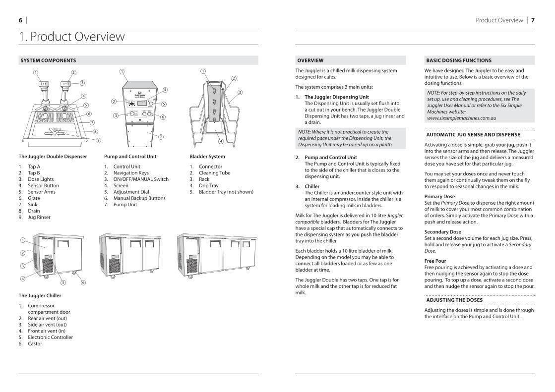
SYSTEM COMPONENTS
The Juggler Double Dispenser
1. Tap A2. Tap B3. Dose Lights4. Sensor Button5. Sensor Arms6. Grate7. Sink8. Drain9. Jug Rinser
Pump and Control Unit
1. Control Unit2. Navigation Keys3. ON/OFF/MANUAL Switch4. Screen5. Adjustment Dial6. Manual Backup Buttons7. Pump Unit
Bladder System
1. Connector2. Cleaning Tube3. Rack4. Drip Tray5. Bladder Tray (not shown)
1. Product Overview
Product Overview l 76 l
The Juggler Chiller
1. Compressor compartment door
2. Rear air vent (out)3. Side air vent (out)4. Front air vent (in)5. Electronic Controller6. Castor
5 6
3
4
1
2
OVERVIEW
The Juggler is a chilled milk dispensing system designed for cafes.
The system comprises 3 main units:
1. The Juggler Dispensing Unit
The Dispensing Unit is usually set fl ush into a cut out in your bench. The Juggler Double Dispensing Unit has two taps, a jug rinser and a drain.
NOTE: Where it is not practical to create the required pace under the Dispensing Unit, the Dispensing Unit may be raised up on a plinth.
2. Pump and Control Unit
The Pump and Control Unit is typically fi xed to the side of the chiller that is closes to the dispensing unit.
3. Chiller
The Chiller is an undercounter style unit with an internal compressor. Inside the chiller is a system for loading milk in bladders.
Milk for The Juggler is delivered in 10 litre Juggler compatible bladders. Bladders for The Juggler have a special cap that automatically connects to the dispensing system as you push the bladder tray into the chiller.
Each bladder holds a 10 litre bladder of milk. Depending on the model you may be able to connect all bladders loaded or as few as one bladder at time.
The Juggler Double has two taps. One tap is for whole milk and the other tap is for reduced fat milk.
BASIC DOSING FUNCTIONS
We have designed The Juggler to be easy and intuitive to use. Below is a basic overview of the dosing functions.
NOTE: For step-by-step instructions on the daily set up, use and cleaning procedures, see The Juggler User Manual or refer to the Six Simple Machines website:www.sixsimplemachines.com.au
AUTOMATIC JUG SENSE AND DISPENSE
Activating a dose is simple, grab your jug, push it into the sensor arms and then release. The Juggler senses the size of the jug and delivers a measured dose you have set for that particular jug.
You may set your doses once and never touch them again or continually tweak them on the fl y to respond to seasonal changes in the milk.
Primary Dose
Set the Primary Dose to dispense the right amount of milk to cover your most common combination of orders. Simply activate the Primary Dose with a push and release action.
Secondary Dose
Set a second dose volume for each jug size. Press, hold and release your jug to activate a Secondary Dose.
Free Pour
Free pouring is achieved by activating a dose and then nudging the sensor again to stop the dose pouring. To top up a dose, activate a second dose and then nudge the sensor again to stop the pour.
ADJUSTING THE DOSES
Adjusting the doses is simple and is done through the interface on the Pump and Control Unit.
215
380
300
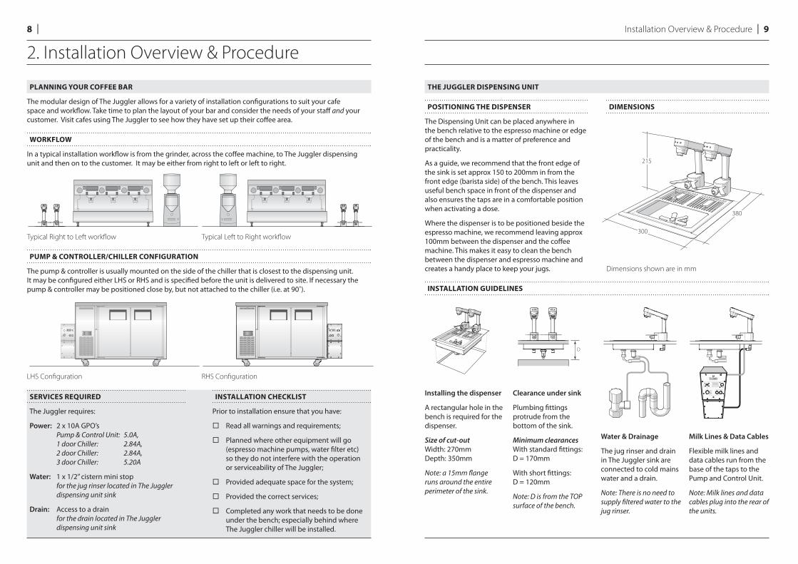
THE JUGGLER DISPENSING UNIT
POSITIONING THE DISPENSER
The Dispensing Unit can be placed anywhere in the bench relative to the espresso machine or edge of the bench and is a matter of preference and practicality.
As a guide, we recommend that the front edge of the sink is set approx 150 to 200mm in from the front edge (barista side) of the bench. This leaves useful bench space in front of the dispenser and also ensures the taps are in a comfortable position when activating a dose.
Where the dispenser is to be positioned beside the espresso machine, we recommend leaving approx 100mm between the dispenser and the coff ee machine. This makes it easy to clean the bench between the dispenser and espresso machine and creates a handy place to keep your jugs.
DIMENSIONS
Dimensions shown are in mm
INSTALLATION GUIDELINES
SERVICES REQUIRED
The Juggler requires:
Power: 2 x 10A GPO’s Pump & Control Unit: 5.0A,1 door Chiller: 2.84A, 2 door Chiller: 2.84A, 3 door Chiller: 5.20A
Water: 1 x 1/2” cistern mini stop for the jug rinser located in The Juggler dispensing unit sink
Drain: Access to a drain for the drain located in The Juggler dispensing unit sink
INSTALLATION CHECKLIST
Prior to installation ensure that you have:
Read all warnings and requirements;
Planned where other equipment will go (espresso machine pumps, water fi lter etc) so they do not interfere with the operation or serviceability of The Juggler;
Provided adequate space for the system;
Provided the correct services;
Completed any work that needs to be done under the bench; especially behind where The Juggler chiller will be installed.
D
2. Installation Overview & Procedure
Installation Overview & Procedure l 98 l
PLANNING YOUR COFFEE BAR
The modular design of The Juggler allows for a variety of installation confi gurations to suit your cafe space and workfl ow. Take time to plan the layout of your bar and consider the needs of your staff and your customer. Visit cafes using The Juggler to see how they have set up their coff ee area.
WORKFLOW
In a typical installation workfl ow is from the grinder, across the coff ee machine, to The Juggler dispensing unit and then on to the customer. It may be either from right to left or left to right.
Typical Right to Left workfl ow Typical Left to Right workfl ow
PUMP & CONTROLLER/CHILLER CONFIGURATION
The pump & controller is usually mounted on the side of the chiller that is closest to the dispensing unit. It may be confi gured either LHS or RHS and is specifi ed before the unit is delivered to site. If necessary the pump & controller may be positioned close by, but not attached to the chiller (i.e. at 90˚).
LHS Confi guration RHS Confi guration
Installing the dispenser
A rectangular hole in the bench is required for the dispenser.
Size of cut-outWidth: 270mm Depth: 350mm
Note: a 15mm fl ange runs around the entire perimeter of the sink.
Clearance under sink
Plumbing fi ttings protrude from the bottom of the sink.
Minimum clearancesWith standard fi ttings:D = 170mm
With short fi ttings:D = 120mm
Note: D is from the TOP surface of the bench.
Water & Drainage
The jug rinser and drain in The Juggler sink are connected to cold mains water and a drain.
Note: There is no need to supply fi ltered water to the jug rinser.
Milk Lines & Data Cables
Flexible milk lines and data cables run from the base of the taps to the Pump and Control Unit.
Note: Milk lines and data cables plug into the rear of the units.
46
0
905195
1100
27
5
75
05
45
73
0A
B
1205195
1400
46
02
75
40
07
30
A7
50
B
1800195
1995
46
02
75
44
57
30
A7
50
B
Installation Overview & Procedure l 1110 l Installation Overview & Procedure
THE JUGGLER CHILLER
OPERATING TEMPERATURE RANGE
The chiller is designed to operate at 1°C to 4°C in up to 40°C ambient and 40% relative humidity.
LOCATING THE CABINET
Location
When positioning the cabinet, avoid direct sunlight and warm draughts etc and areas where the refrigeration unit could be exposed to water or moisture. The cabinet must NOT be situated where it is aff ected by warm or hot air from adjacent equipment as this will compromise the airfl ow and performance of the cabinet.
The cabinet must be positioned on a level surface for the doors to shut and seal correctly and to prevent the condensate tray from overfl owing.
Allow adequate space for the doors to open fully, including the compressor compartment door.
Ensure all packaging is removed from the cabinet.
Ventilation
Ensure there is always at least a 150mm gap around the back and the refrigeration unit side of the cabinet. It is critical that the hot refrigeration exhaust air is not restricted and that it can easily fl ow out and away from the front of the cabinet. Never store cardboard cartons or other items in front of the refrigeration unit. The ventilation slots on the refrigeration unit front cover must be kept clear at all times.
Normal operating conditions should not exceed the operating temperature range.
Power Supply
The cabinet is supplied with a fl exible power cord and plug which exits the rear of the cabinet. Before fi nal positioning of the cabinet, pull the power cord out from the rear compartment and connect to the power supply. For convenience, any surplus cord length may be left inside the cabinet compartment.
WARNING: Do NOT overload the power supply. See the rating label inside the cabinet for power supply and current draw.
POSITIONING THE CABINET
Castors
The castors screw into the castor mounting plates in the bottom of the cabinet. Where locking castors are supplied, they should be fi tted to the to the front of the cabinet.
OPERATION
Automatic Start-Up
Connect the cabinet to the mains power supply and check operation of the refrigeration unit and electronic controller. Ensure the cabinet power switch is turned on.
IMPORTANT: If the cabinet has been on its back, leave for 30 minutes before running.
Power Switch
The cabinet is fi tted with a power switch, located beside the electronic controller. Open the compressor cabinet door to access the switch.
Refrigeration Unit
The compressor and the condenser and evaporator fans should all operate within two minutes from the time the cabinet is plugged in. This may be verifi ed by listening for compressor switch-on and checking for air movement inside the cabinet. The compressor and condenser fan will switch off when the cabinet internal air reaches a pre-set temperature.
Electronic Controller
When the cabinet is connected to the power supply, the electronic controller will display the current cabinet temperature. The compressor symbol will come on after a few minutes, indicating the compressor and condenser fan is operating.
To ensure effi cient operation, the electronic controller forces regular defrosts. During the defrost cycle, the compressor and condenser fan switch off and the evaporator fan stays on.
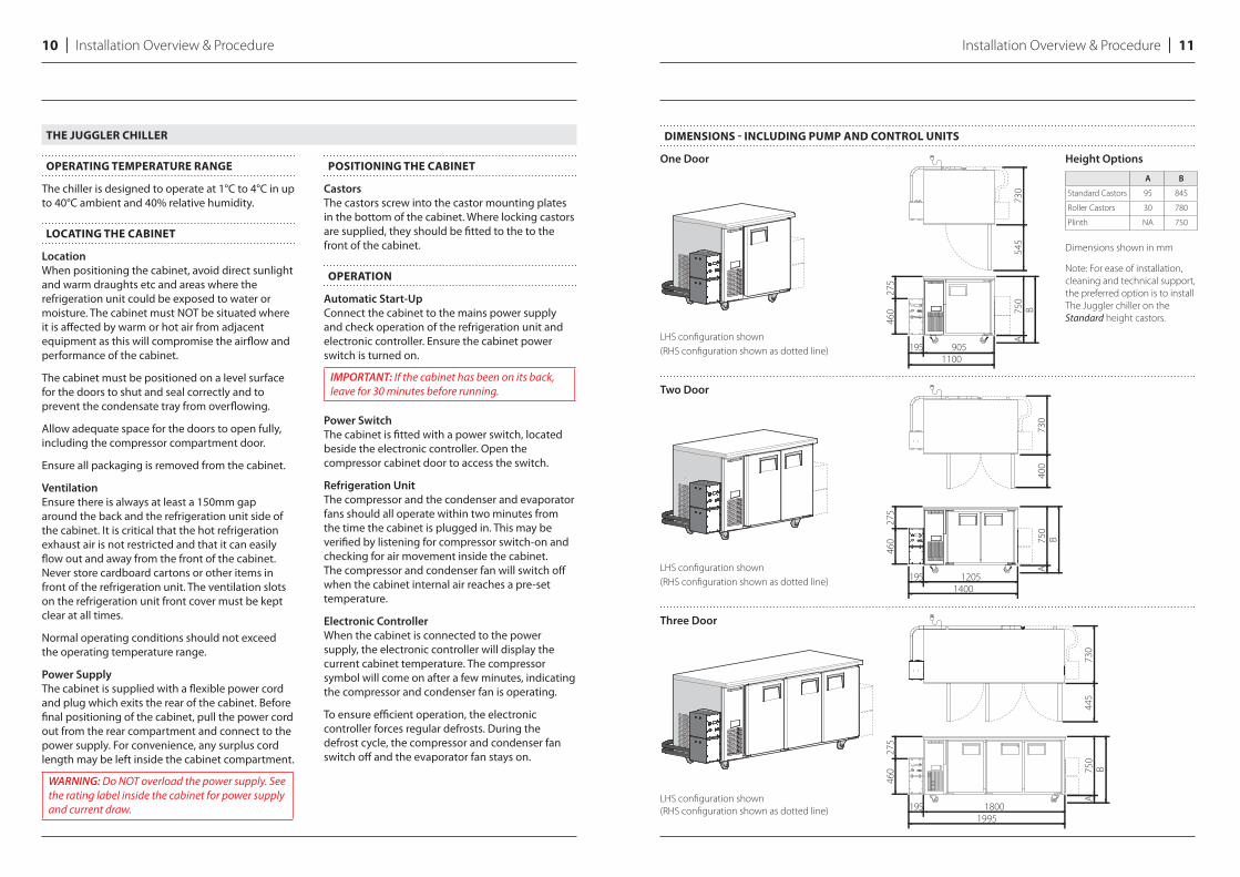
DIMENSIONS - INCLUDING PUMP AND CONTROL UNITS
One Door Height Options
LHS confi guration shown
(RHS confi guration shown as dotted line)
Two Door
LHS confi guration shown
(RHS confi guration shown as dotted line)
Three Door
LHS confi guration shown
(RHS confi guration shown as dotted line)
A B
Standard Castors 95 845
Roller Castors 30 780
Plinth NA 750
Dimensions shown in mm
Note: For ease of installation,
cleaning and technical support,
the preferred option is to install
The Juggler chiller on the
Standard height castors.
Note:
‘L’ symbol
at top
Note:
‘r’ symbol
at top
Bracket
(fixed to LHS
of Chiller)
Bracket
(fixed to RHS
of Chiller)
Installation Overview & Procedure l 1312 l Installation Overview & Procedure
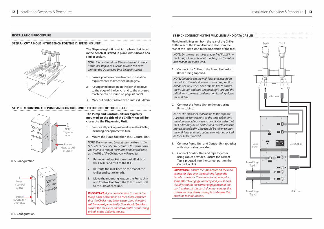
INSTALLATION PROCEDURE
STEP A - CUT A HOLE IN THE BENCH FOR THE DISPENSING UNIT
The Dispensing Unit is set into a hole that is cut
in the bench. It is fi xed in place with silicone or a
similar sealant.
NOTE: It is best to set the Dispensing Unit in place as the last step to ensure the silicone can cure without the Dispensing Unit being disturbed.
1. Ensure you have considered all installation requirements as described on page 9.
2. A suggested position on the bench relative to the edge of the bench and to the espresso machine can be found on pages 8 and 9.
3. Mark out and cut a hole: w270mm x d350mm.
STEP B - MOUNTING THE PUMP AND CONTROL UNITS TO THE SIDE OF THE CHILLER
LHS Confi guration
RHS Confi guration
The Pump and Control Units are typically
mounted on the side of the Chiller that will be
closest to the Dispensing Unit..
1. Remove all packing material from the Chiller, including clear protective fi lm.
2. Mount the Pump Unit then the, i Control Unit.
NOTE: The mounting bracket may be fi xed to the LHS side of the chiller by default. If this is the casef you intend to mount the Pump and Control Units on the RHS of the Chiller, you will need to:
1. Remove the bracket form the LHS side of the Chiller and fi x it to the RHS.
2. Re-route the milk lines on the rear of the chiller and cut to length.
3. Move the mounting lugs on the Pump Unit and Control Unit from the RHS of each unit to the LHS of each unit.
IMPORTANT: If you do not intend to mount the Pump and Control Units on the Chiller, consider that the Chiller may be on castors and therefore will be moved periodically. Care should be taken so that the milk lines and data cables cannot snag or kink as the Chiller is moved.
STEP C - CONNECTING THE MILK LINES AND DATA CABLES
Flexible milk lines run from the rear of the Chiller to the rear of the Pump Unit and also from the rear of the Pump Unit to the underside of the taps.
NOTE: Ensure that all tubes are pushed FULLY into the fi ttings. Take note of all markings on the tubes and rear of the Pump Unit.
1. Connect the Chiller to the Pump Unit using 8mm tubing supplied.
NOTE: Carefully cut the milk lines and insulation material so the milk lines are as short as practical but do not kink when bent. Use zip ties to ensure the insulation ends are wrapped tight around the milk lines to prevent condensation forming along the milk lines.
2. Connect the Pump Unit to the taps using 8mm tubing.
NOTE: The milk lines that run up to the taps are supplied the same length as the data cables and therefore should not need to be cut. Consider that the Chiller may be on castors and therefore will be moved periodically. Care should be taken so that the milk lines and data cables cannot snag or kink as the Chiller is moved.
3. Connect Pump Unit and Control Unit together with short cable provided.
4. Connect Control Unit and taps together using cables provided. Ensure the correct Tap is plugged into the correct port on the Controller Unit.
IMPORTANT: Ensure the small catch on the male connector clips over the retaining lug on the female connector. The connectors can require some eff ort to engage correctly and you should visually confi rm the correct engagement of the catch and lug. If this catch does not engage the connector may slowly uncouple and cause the machine to malfunction.
Cafe milk tap system
TM
MODEL: THE JUGGLER
240V~50Hz 140WRated Pressure: 200 kPaJug Washer Max Pressure: 240kPa
DO NOT EXPOSE TO WATER JETSPatent Pending l Registered Design l Made in Australia
TO TAP B
TO TAP B
TO CONTROLLERUNIT
TO PUMPUNIT
230-240v50Hz
TO TAP A
TO TAP A
FROM FRIDGETAP B
FROM FRIDGETAP A
From Fridge
Tap A
From Fridge
Tap B
Milk Lines
Milk Lines
Data CablesData
Cable
Tap ATap B
Flexible braided
hose supplied
Flexible drain
hose supplied
1/2” BSP cistern cock
(not included)
Cafe drain
2
3
1
Installation Overview & Procedure l 1514 l Installation Overview & Procedure
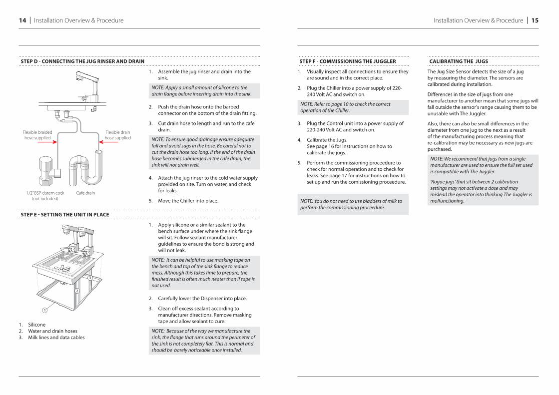
STEP D - CONNECTING THE JUG RINSER AND DRAIN
1. Assemble the jug rinser and drain into the sink.
NOTE: Apply a small amount of silicone to the drain fl ange before inserting drain into the sink.
2. Push the drain hose onto the barbed connector on the bottom of the drain fi tting.
3. Cut drain hose to length and run to the cafe drain.
NOTE: To ensure good drainage ensure adequate fall and avoid sags in the hose. Be careful not to cut the drain hose too long. If the end of the drain hose becomes submerged in the cafe drain, the sink will not drain well.
4. Attach the jug rinser to the cold water supply provided on site. Turn on water, and check for leaks.
5. Move the Chiller into place.
STEP E - SETTING THE UNIT IN PLACE
1. Apply silicone or a similar sealant to the bench surface under where the sink fl ange will sit. Follow sealant manufacturer guidelines to ensure the bond is strong and will not leak.
NOTE: It can be helpful to use masking tape on the bench and top of the sink fl ange to reduce mess. Although this takes time to prepare, the fi nished result is often much neater than if tape is not used.
2. Carefully lower the Dispenser into place.
3. Clean off excess sealant according to manufacturer directions. Remove masking tape and allow sealant to cure.
NOTE: Because of the way we manufacture the sink, the fl ange that runs around the perimeter of the sink is not completely fl at. This is normal and should be barely noticeable once installed.
STEP F - COMMISSIONING THE JUGGLER
1. Visually inspect all connections to ensure they are sound and in the correct place.
2. Plug the Chiller into a power supply of 220-240 Volt AC and switch on.
NOTE: Refer to page 10 to check the correct operation of the Chiller.
3. Plug the Control unit into a power supply of 220-240 Volt AC and switch on.
4. Calibrate the Jugs. See page 16 for instructions on how to calibrate the jugs.
5. Perform the commissioning proceedure to check for normal operation and to check for leaks. See page 17 for instructions on how to set up and run the comissioning proceedure.
NOTE: You do not need to use bladders of milk to perform the commissioning proceedure.
CALIBRATING THE JUGS
The Jug Size Sensor detects the size of a jug by measuring the diameter. The sensors are calibrated during installation.
Diff erences in the size of jugs from one manufacturer to another mean that some jugs will fall outside the sensor's range causing them to be unusable with The Juggler.
Also, there can also be small diff erences in the diameter from one jug to the next as a result of the manufacturing process meaning that re-calibration may be necessary as new jugs are purchased.
NOTE: We recommend that jugs from a single manufacturer are used to ensure the full set used is compatible with The Juggler.
'Rogue jugs' that sit between 2 calibration settings may not activate a dose and may mislead the operator into thinking The Juggler is malfunctioning.
1. Silicone 2. Water and drain hoses 3. Milk lines and data cables
Installation Overview & Proceedure l 1716 l Installation Overview & Proceedure
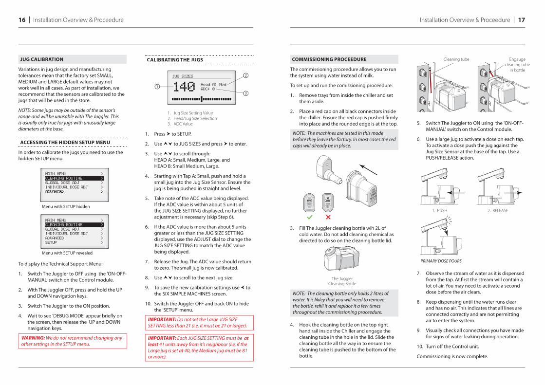
COMMISSIONING PROCEEDURE
The commissioning proceedure allows you to run the system using water instead of milk.
To set up and run the comissioning proceedure:
1. Remove trays from inside the chiller and set them aside.
2. Place a red cap on all black connectors inside the chiller. Ensure the red cap is pushed fi rmly into place and the rounded edge is at the top.
NOTE: The machines are tested in this mode before they leave the factory. In most cases the red caps will already be in place.
3. Fill The Juggler cleaning bottle wih 2L of cold water. Do not add cleaning chemical as directed to do so on the cleaning bottle lid.
NOTE: The cleaning bottle only holds 2 litres of water. It is likley that you will need to remove the bottle, refi ll it and replace it a few times throughout the commissioning proceedure.
4. Hook the cleaning bottle on the top right hand rail inside the Chiller and engage the cleaning tube in the hole in the lid. Slide the cleaning bottle all the way in to ensure the cleaning tube is pushed to the bottom of the bottle.
5. Switch The Juggler to ON using the 'ON-OFF-MANUAL' switch on the Control module.
6. Use a large jug to activate a dose on each tap. To activate a dose push the jug against the Jug Size Sensor at the base of the tap. Use a PUSH/RELEASE action.
7. Observe the stream of water as it is dispensed from the tap. At fi rst the stream will contain a lot of air. You may need to activate a second dose before the air clears.
8. Keep dispensing until the water runs clear and has no air. This indicates that all lines are connected correctly and are not permitting air to enter the system.
9. Visually check all connections you have made for signs of water leaking during operation.
10. Turn off the Control unit.
Commissioning is now complete.
Cleaning tube Engauge
cleaning tube
in bottle
The Juggler
Cleaning Bottle
PRIMARY DOSE POURS
1. PUSH 2. RELEASE
JUG CALIBRATION
Variations in jug design and manufacturing tolerances mean that the factory set SMALL, MEDIUM and LARGE default values may not work well in all cases. As part of installation, we recommend that the sensors are calibrated to the jugs that will be used in the store.
NOTE: Some jugs may be outside of the sensor's range and will be unusable with The Juggler. This is usually only true for jugs with unusually large diameters at the base.
ACCESSING THE HIDDEN SETUP MENU
In order to calibrate the jugs you need to use the hidden SETUP menu.
To display the Technical Support Menu:
1. Switch The Juggler to OFF using the 'ON-OFF-MANUAL' switch on the Control module.
2. With The Juggler OFF, press and hold the UP and DOWN navigation keys.
3. Switch The Juggler to the ON position.
4. Wait to see 'DEBUG MODE' appear briefl y on the screen, then release the UP and DOWN navigation keys.
WARNING: We do not recommend changing any other settings in the SETUP menu.
CALIBRATING THE JUGS
1. Press to SETUP.
2. Use to JUG SIZES and press to enter.
3. Use to scroll through: HEAD A: Small, Medium, Large, and HEAD B: Small Medium, Large.
4. Starting with Tap A: Small, push and hold a small jug into the Jug Size Sensor. Ensure the jug is being pushed in straight and level.
5. Take note of the ADC value being displayed. If the ADC value is within about 5 units of the JUG SIZE SETTING displayed, no further adjustment is necessary (skip Step 6).
6. If the ADC value is more than about 5 units greater or less than the JUG SIZE SETTING displayed, use the ADJUST dial to change the JUG SIZE SETTING to match the ADC value being displayed.
7. Release the Jug. The ADC value should return to zero. The small jug is now calibrated.
8. Use to scroll to the next jug size.
9. To save the new calibration settings use to the SIX SIMPLE MACHINES screen.
10. Switch the Juggler OFF and back ON to hide the 'SETUP' menu.
IMPORTANT: Do not set the Large JUG SIZE SETTING less than 21 (i.e. it must be 21 or larger).
IMPORTANT: Each JUG SIZE SETTING must be at least 41 units away from it's neighbour (i.e. if the Large jug is set at 40, the Medium jug must be 81 or more).
In order to calibrate the jugs you need to use the hidden SETUP menu.
To display the Technical Support Menu:
Menu with SETUP hidden
Menu with SETUP revealed
CALIBRATING THE JUGS
1. Jug Size Setting Value
2. Head/Jug Size Selection
3. ADC Value
1
2
3
3. System Settings
System Settings l 1918 l
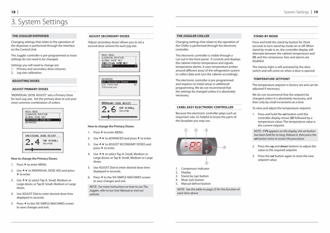
THE JUGGLER DISPENSER
Changing settings that relate to the operation of the dispenser is performed through the interface on the Control Unit.
The Juggler controller is pre-programmed so most settings do not need to be changed.
Settings you will need to change are:1. Primary and secondary dose volumes,2. Jug size calibration.
ADJUSTING DOSES
ADJUST PRIMARY DOSES
'INDIVIDUAL DOSE ADJUST' sets a Primary Dose for each jug size. Set the primary dose to suit your most common combination of orders.
How to change the Primary Doses:
1. Press to enter MENU.
2. Use to INDIVIDUAL DOSE ADJ and press to enter.
3. Use to select Tap A: Small, Medium or Large doses; or Tap B: Small, Medium or Large doses.
4. Use ADJUST Dial to enter desired dose time displayed in seconds.
5. Press to the SIX SIMPLE MACHINES screen to save changes and exit.
ADJUST SECONDARY DOSES
‘Adjust secondary doses’ allows you to set a second dose volume for each jug size.
How to change the Primary Doses:
1. Press to enter MENU.
2. Use to ADVANCED and press to enter.
3. Use to ADJUST SECONDARY DOSES and press to enter.
4. Use to select Tap A: Small, Medium or Large doses; or Tap B: Small, Medium or Large doses.
5. Use ADJUST Dial to enter desired dose time displayed in seconds.
6. Press to the SIX SIMPLE MACHINES screen to save changes and exit.
NOTE: For more instructions on how to use The Juggler, refer to our User Manual or visit our website.
THE JUGGLER CHILLER
Changing settings that relate to the operation of the Chiller is performed through the electronic controller.
The electronic controller is visible through a cut-out in the front panel. It controls and displays the cabinet interior temperature and signals temperature alarms. It uses temperature probes around diff erent areas of the refrigeration system to collect data and runs the cabinet accordingly .
The electronic controller is pre-programmed and requires no initial setup or additional programming. We do not recommend that the settings be changed unless it is absolutely necessary.
CAREL EASY ELECTRONIC CONTROLLER
Because the electronic controller plays such an important role, it’s helpful to know the parts of the faceplate you may use.
1. Compressor Indicator2. Display3. Stand-by (up) button4. Mute (set) button5. Manual defrost button
NOTE: See the table on page 25 for the function of each item above.
STAND-BY MODE
Press and hold the stand-by button for three seconds to turn stand-by mode on or off . When stand-by mode is on, the controller display will alternate between the cabinet temperature and Of, and the compressor, fans and alarms are disabled.
The interior light is still activated by the door switch and will come on when a door is opened.
TEMPERATURE SETPOINT
The temperature setpoint is factory set and can be adjusted if necessary.
We do not recommend that the setpoint be changed unless it is absolutely necessary, and then only by small increments at a time.
To view and adjust the temperature setpoint:
1. Press and hold the set button until the controller display shows SEt followed by a temperature value. The temperature value is the current setpoint.
NOTE: If PS appears on the display, the set button has been held for to long. Release it, then press the set button twice to restart the procedure.
2. Press the up and down buttons to adjust the value to the required setpoint.
3. Press the set button again to store the new setpoint value.
1 2 3
5
4
20 l System Settings
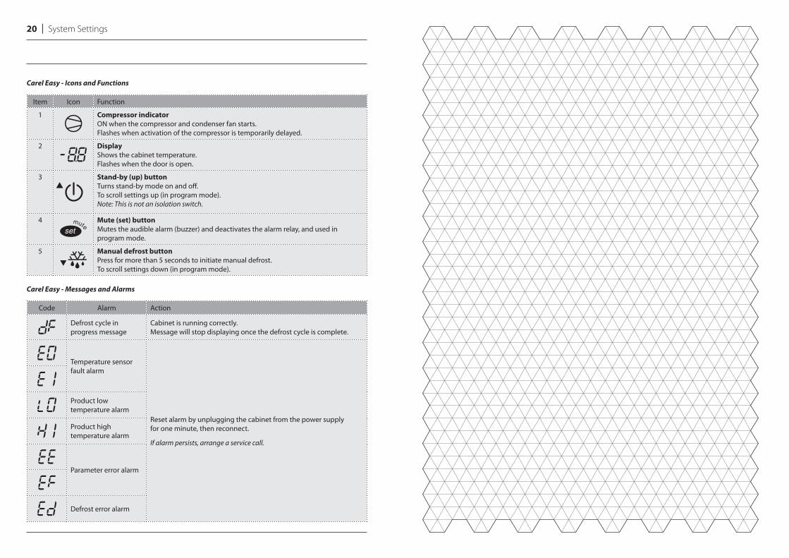
Carel Easy - Icons and Functions
Item Icon Function
1 Compressor indicator
ON when the compressor and condenser fan starts. Flashes when activation of the compressor is temporarily delayed.
2 Display
Shows the cabinet temperature. Flashes when the door is open.
3 Stand-by (up) button Turns stand-by mode on and off . To scroll settings up (in program mode).Note: This is not an isolation switch.
4 Mute (set) button
Mutes the audible alarm (buzzer) and deactivates the alarm relay, and used in program mode.
5 Manual defrost button
Press for more than 5 seconds to initiate manual defrost. To scroll settings down (in program mode).
Carel Easy - Messages and Alarms
Code Alarm Action
Defrost cycle in progress message
Cabinet is running correctly. Message will stop displaying once the defrost cycle is complete.
Temperature sensor fault alarm
Reset alarm by unplugging the cabinet from the power supply for one minute, then reconnect.
If alarm persists, arrange a service call.
Product low temperature alarm
Product high temperature alarm
Parameter error alarm
Defrost error alarm

At Six Simple Machines we are always looking for ways to improve our products.The illustrations in this guide may differ slightly from the actual product.
Patent Pending l Made in AustraliaD00058.2 A01 l © 2016 SIX SIMPLE MACHINES Pty Ltd