the scf interim industry standard · msc 87, held in may 2010, stressed the importance of...
TRANSCRIPT

SCF Interim Industry Standard – 7 March 2016
Page-1
The SCF Interim Industry Standard
7 March 2016
Approved for submission to MSC 96
SCF Interim Industry Standard – 7 March 2016
Page-2
Introduction
Goal-Based Ship Construction Standards for Bulk carriers and Oil Tankers (GBS) define high-level safety objectives to be achieved through “functional requirements” and “detailed requirements”. The conformity of rules and regulations of classification societies with the “functional requirements” are to be verified by procedures. GBS, accordingly, has a five-tier structure consisting of Tier I – Goals, Tier II – Functional requirements, Tier III – Verification of conformity, Tier IV – Rules and regulations for ship design and construction and Tier V – Industry practices and standards. The IMO supervises Tier I, II, III and IV, whereas Tier V is dealt with on industry level. In order to ensure design transparency, one of the “functional requirements” of GBS, each Ship is required by the International Convention for the Safety of Life at Sea (SOLAS) to have specific information and documentation on ship design and construction onboard the Ship throughout the Ship’s life. This set of documents, drawings and information is collectively called the Ship Construction File (SCF). The documents and drawings required to be provided as part of the SCF contain shipbuilding know-how. Therefore, all who have access to such sensitive information is expected to give due consideration to the intellectual property rights (IPR). At the 2009 Tripartite Meeting (Shipowners, Shipbuilders and Classification Societies) 1 it was agreed to develop a cross industry concept for ensuring both design transparency and the protection of intellectual property (IP) which needs to be based on safekeeping certain SCF information at a dedicated Archive Center ashore. MSC 87, held in May 2010, stressed the importance of addressing both design transparency and IPR, supported the cross-industry model presented and noted these proposals. It was also acknowledged by MSC 87 that detailed standard for SCF would be developed by the industry (Industry Standard). GBS is applied only to bulk carriers and oil tankers of 150 meters in length and above. GBS-related rules (amendments to SOLAS Ch. II-1 and regulations concerning GBS) came into effect on January 1, 2012, and the members of the International Association of Classification Societies (IACS) developed GBS compatible structural rules. The Industry Standard presented in this document corresponds to GBS Tier V and may be referred to or quoted in the rules and regulations for ship design and construction (Tier IV). The SCF Industry Standard establishes procedures for implementing the Ship Construction File (SCF), which is defined by four IMO documents – MSC.287 (87) (adopted at MSC 87 on 20 May 2010), MSC.290 (87) (adopted at MSC 87 on 21 May 2010), MSC.296 (87) (adopted at MSC 87 on 20 May 2010) and MSC.1/Circ.1343 (circulated on 2 June 2010) and supplement those IMO documents based on MSC 87/5/4 (endorsed by MSC 87). The Industry Standard was developed in consultation with a cross industry group of the following industry organizations:
CANSI (China Association of the National Shipbuilding Industry); CESA (Community of European Shipyards’ Associations); KOSHIPA (Korea Offshore & Shipbuilding Association);
1 Tripartite Meeting is a regular annual cross-industry meeting between the high level participants from Shipowners, Shipbuilders and Classification Societies to discuss and agree on prospective collective actions that will contribute to the development of maritime industry.
SCF Interim Industry Standard – 7 March 2016
Page-3 SAJ (The Shipbuilders’ Association of Japan);
SCA (Shipbuilders Council of America); BIMCO; ICS (International Chamber of Shipping); INTERCARGO (The International Association of Dry Cargo Shipowners); INTERTANKO (The International Association of Independent Tanker Owners); OCIMF (Oil Companies International Marine Forum); and IACS (International Association of Classification Societies, Ltd.)
The cross industry group has agreed on the following principles.
The SCF Interim Industry Standard (SCF IS) serves as industry guidance and therefore do not oblige parties to fully follow the contents but rather provide principles, which will facilitate agreement being reached for each Ship. Such agreements and the resulting commitments will reflect specific individual situations. In other words, the purpose of the SCF IS is to promote common understanding of the industry issues involved, and to facilitate agreement on individual projects.
Furthermore, the SCF IS is intended to provide guidance on the principles of how the various parties manage the information and on taking various actions pertaining to SCF Information. The intention is to provide users of the SCF IS with practical assistance on the administrative, technical, operational and document management aspects.
Additional, more detailed guidance for the practical implementation of the SCF IS is provided in the Interim Supplementary Guidance (SCF SG) of the SCF IS.
The principles outlined in the SCF IS could also be used to facilitate the management of information other than the SCF required by GBS (entered into force in January 2012), which could then be kept according to a voluntary private agreement between, for example, the Shipowner, IP-Holder and the Archive Center.
The Shipbuilder prepares the relevant SCF Information for design and construction transparency, (see Ch. 3.1)
The Shipowner keeps and updates the SCF Information. (see Ch. 3.4)
SCF Information is to include necessary and sufficient information concerning the Ship’s hull structure in order to facilitate the Ship’s safe operation, maintenance, inspections and repair as well as response in emergency situations. (see Ch. 2.1)
Access Right Holders, need to give due consideration to the IPR. (see Ch. 3.2).
All parties should manage SCF Information in accordance with the access and safekeeping principles provided in the SCF IS. (see Ch. 3.2)
The SCF Supplement Ashore is kept at an Archive Center to ensure both transparency of the information and protection of IP. (see Ch 2.1)
Standard storage location of various documents and drawings is provided in Table 2.
The Archive Center keeps the SCF Supplement Ashore and a full copy of the SCF Onboard and discloses them to Access Right Holders through the Shipowner. (see Ch. 3.2 and 3.3)
SCF Interim Industry Standard – 7 March 2016
Page-4 1. Definitions
(a) Access Right Holders are persons and institutions that have a right to access SCF Information, e.g. Shipowner, Seafarer, Ship operator and their Sub-contractors for the safe operation of the Ship and/or due to other legitimate obligation, authorities such as representatives of flag States, coastal States and their Recognized Organizations for Port State Controls or marine accident investigations, etc. as well as registered classification societies for surveys.
(b) Archive Center means a facility tasked with storage, safekeeping and managing access of to the SCF Information that it holds.
(c) IP-Holder means an entity which possesses rights related to the intellectual property in the Ship’s SCF Information. The entity may cover the Shipbuilder, Shiprepairer, Equipment maker, Shipowner, etc.
(d) Intellectual Property (IP) refers to creations of the mind which is divided into industrial property and copyright. In the field of shipbuilding, IP covers but is not limited to: proprietary technical descriptions, calculations, test results, plans, drawings, designs, models, specifications, reports and any other knowledge assets, registered and unregistered, which are instrumental for competitiveness and company strategies of the IP holder.
(e) Rules means not only the rules by Classification Societies but also other rules and regulations that are sufficient to demonstrate the Ship meets that the GBS functional requirements concerning the hull structure.
(f) Safe Operation Purpose means a purpose related to safe operations, maintenance, inspections and repair (structural work to maintain the structural strength assumed at the time of construction, such as restoring damaged parts to their original state and reinforcing parts with insufficient strength) of the Ship, and responses in emergency situations of the Ship.
(g) SCF Information means a collection of information composed of the SCF Onboard and SCF Supplement Ashore. It is a general term given to a collection of information that is sufficient to demonstrate that the Ship meets the GBS functional requirements concerning the hull structure and is needed for the safe operation of the Ship, maintenance, inspections and repair as well as in emergency situations. In this document, the term “SCF Information” means the SCF Onboard and/or SCF Supplement Ashore, irrespective of whether it refers to partial or the whole, or to the original or a copy.
(h) SCF Onboard means SCF Information that is required to be kept onboard the Ship at all times.
(i) SCF Supplement Ashore means SCF Information that is Highly IP sensitive information but not absolutely necessary and relevant to be kept onboard the Ship at all times. Usually, it means information that is kept only at the Archive Center.
(j) Seafarer means individuals who are employed and work regularly onboard the Ship.
(k) Ship means an oil tanker of 150 meters in length and above or a bulk carrier of 150 meters in length and above, constructed with single deck, top-side tanks and hopper side tanks in cargo spaces, excluding ore carrier and combination carrier, that fulfills one of the following criteria:
i. The building contract is placed on or after July 1, 2016; ii. In the absence of a building contract, the keels are laid or are at a similar stage of
construction on or after July 1, 2017; or iii. The delivery is on or after July 1, 2020.
(l) Shipowner means an entity that has entered into possession of a Ship through acts like a purchase or a transfer and engaged in safekeeping and updating of SCF Information during the
SCF Interim Industry Standard – 7 March 2016
Page-5 Ship’s operational lifetime in accordance with amendments to the SOLAS Convention Chapter
II-1 Part A-1. These tasks in relation to management of SCF Information may also be tasked to Ship operators, management companies etc.
(m) Sub-contractor means an entity (such as a Shipbuilder for repair/conversion) that is contracted, directly or indirectly, by the Shipowner.
(n) Third Party means those other than the IP-Holder, Shipowner, Seafarer, Ship operator, Ship management company. Engineering houses and/or consultants employed by the Shipowner, Seafarer, Ship operator or Ship management company form a part of Third Party.
(o) Update means promptly updating SCF Information when any modification is made to the Ship that requires a change or addition of SCF Information at any major event, including, but not limited to, substantial repair, Conversion or any modification to the Ship structure, or the updated portion of SCF Information.
SCF Interim Industry Standard – 7 March 2016
Page-6 2. SCF Information
2.1. Composition of SCF Information and Scope of Application
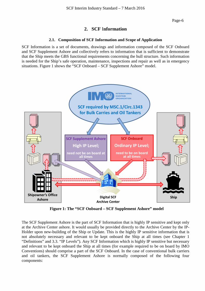
SCF Information is a set of documents, drawings and information composed of the SCF Onboard and SCF Supplement Ashore and collectively refers to information that is sufficient to demonstrate that the Ship meets the GBS functional requirements concerning the hull structure. Such information is needed for the Ship’s safe operation, maintenance, inspections and repair as well as in emergency situations. Figure 1 shows the “SCF Onboard – SCF Supplement Ashore” model.
Figure 1: The “SCF Onboard – SCF Supplement Ashore” model
The SCF Supplement Ashore is the part of SCF Information that is highly IP sensitive and kept only at the Archive Center ashore. It would usually be provided directly to the Archive Center by the IP-Holder upon new-building of the Ship or Update. This is the highly IP sensitive information that is not absolutely necessary and relevant to be kept onboard the Ship at all times (see Chapter 1 “Definitions” and 3.3. “IP Levels”). Any SCF Information which is highly IP sensitive but necessary and relevant to be kept onboard the Ship at all times (for example required to be on board by IMO Conventions) should comprise a part of the SCF Onboard. In the case of conventional bulk carriers and oil tankers, the SCF Supplement Ashore is normally composed of the following four components:
SCF required by MSC.1/Circ.1343 for Bulk Carries and Oil Tankers
SCF Supplement Ashore
High IP Level;need not be on board at
all times
SCF Onboard
Ordinary IP Level;need to be on board
at all times
Digital SCFArchive Center
Shipowner’s Office Ashore Ship

SCF Interim Industry Standard – 7 March 2016
Page-7 • full “Detailed structural strength calculation” document(2)(see also page 24);
• full “Detailed fatigue life calculation” document(3)( see also page 36); • “Yard plans” drawings(4)(see also page 32) ;and • Master “Lines plan” drawing(5)( see also page 34).
2.2. Definition of SCF Information
The list of information to be included in the SCF is provided in Table 1. The actual names and sets of such documents and drawings may differ from those listed in the example documents or drawings as they depend on each Shipbuilder’s drawing system. The information provided may be in more than one document or drawing with appropriate names. Explanatory notes are provided below the Table.
This Table is not identical with the Appendix to MSC.1/Circ.1343, but includes additional items and explanations which are considered to be relevant to be included in the SCF by the cross industry group..
(2) Full “Detailed strength calculation” documents contain the full bulky output of structural strength calculations, which is defined under Item 3-2 contained in Annex. Summarized information on structural strength calculation is available on board through documents such as Item 3-3 and 3-3A (Plan showing highly stressed areas prone to yielding and/or buckling). (3) Full “Detailed fatigue life calculation” documents contain the full bulky output of fatigue life calculations, which is defined under Item 4-1 contained in Annex. Summarized information on fatigue is available on board through document Item 4-2 (Plan showing areas prone to fatigue). (4) “Yard plans” drawings – besides scantling information of structural members – contain also sensitive proprietary information on fabrication processes. The scantling information of structural members to fulfil the day-to-day needs on board is, however, available on board, by means of Item 3-5 (Key construction plans) and Item 3-6 (Net scantlings of structural constituent parts) defined in Annex.. (5) Master “Lines plan” is a master drawing displaying the detailed hull form of the entire ship. Hull form information frequently required is readily made available on board, by means of Item 3-5 (Key construction plans) defined in Annex. Hull form information needed in emergency situations is also encrypted and stored on ship loading computers on board as numerical data. (Refer to Item 3-11 “Equivalent to Lines plan” defined in Annex, too.)
SCF Interim Industry Standard – 7 March 2016
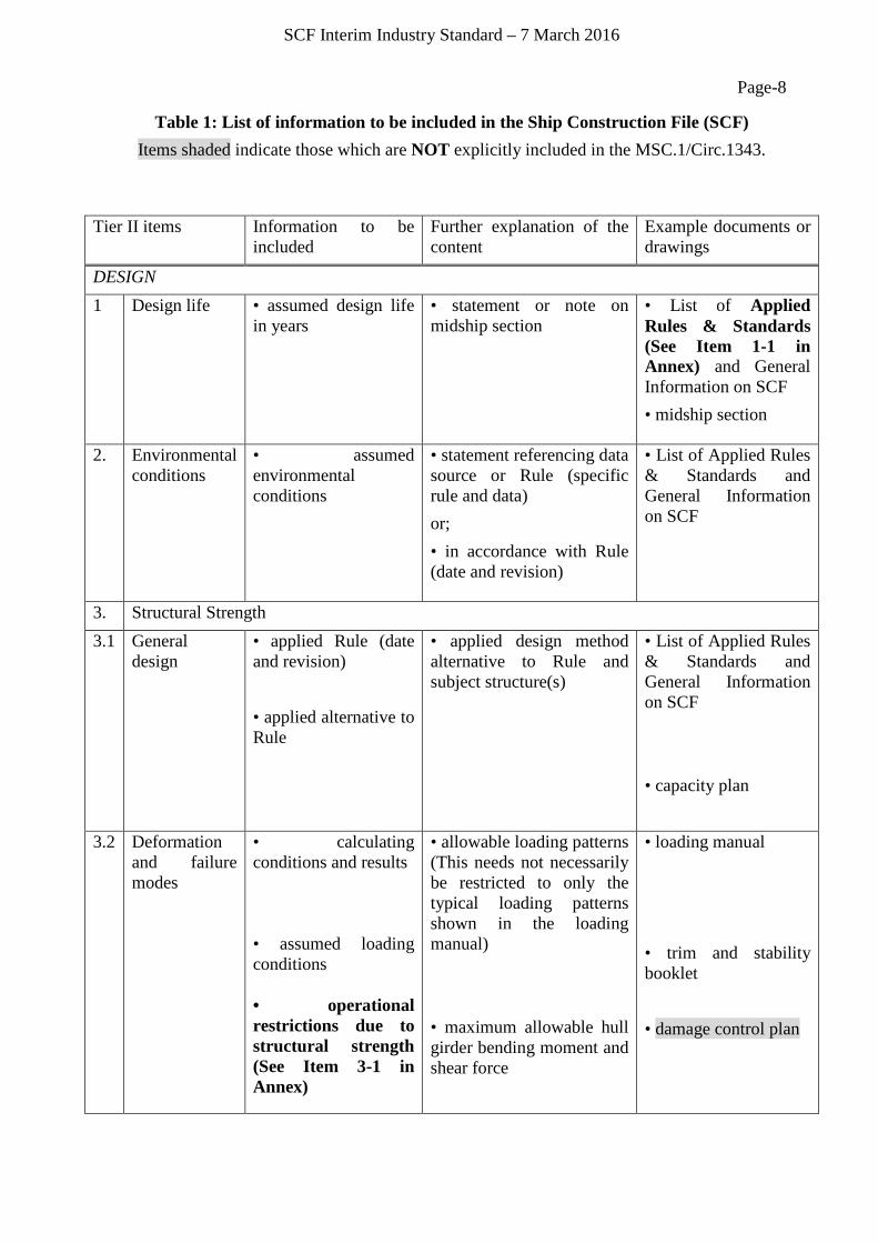
Page-8 Table 1: List of information to be included in the Ship Construction File (SCF)
Items shaded indicate those which are NOT explicitly included in the MSC.1/Circ.1343.
Tier II items Information to be included
Further explanation of the content
Example documents or drawings
DESIGN 1 Design life • assumed design life
in years • statement or note on midship section
• List of Applied Rules & Standards (See Item 1-1 in Annex) and General Information on SCF • midship section
2. Environmental conditions
• assumed environmental conditions
• statement referencing data source or Rule (specific rule and data) or; • in accordance with Rule (date and revision)
• List of Applied Rules & Standards and General Information on SCF
3. Structural Strength 3.1 General
design
• applied Rule (date and revision) • applied alternative to Rule
• applied design method alternative to Rule and subject structure(s)
• List of Applied Rules & Standards and General Information on SCF • capacity plan
3.2 Deformation and failure modes
• calculating conditions and results • assumed loading conditions • operational restrictions due to structural strength (See Item 3-1 in Annex)
• allowable loading patterns (This needs not necessarily be restricted to only the typical loading patterns shown in the loading manual) • maximum allowable hull girder bending moment and shear force
• loading manual • trim and stability booklet • damage control plan
SCF Interim Industry Standard – 7 March 2016
Page-9 Tier II items Information to be
included Further explanation of the content
Example documents or drawings
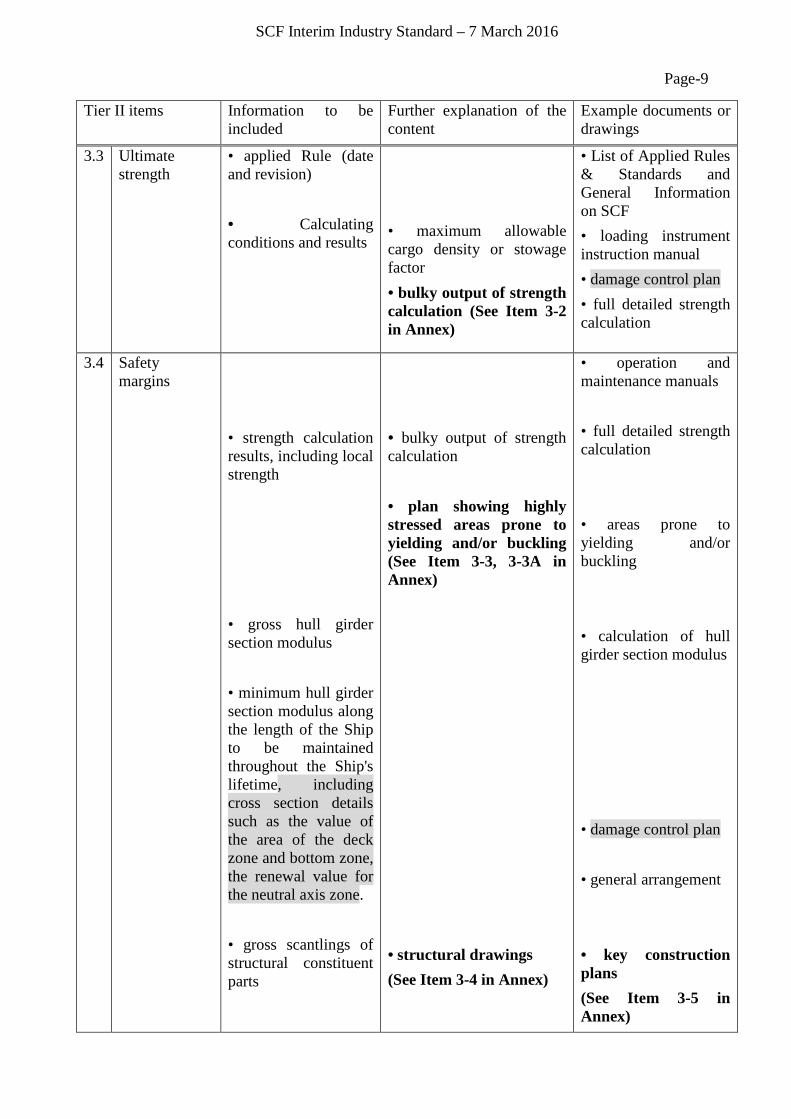
3.3 Ultimate strength
• applied Rule (date and revision) • Calculating conditions and results
• maximum allowable cargo density or stowage factor • bulky output of strength calculation (See Item 3-2 in Annex)
• List of Applied Rules & Standards and General Information on SCF • loading instrument instruction manual • damage control plan • full detailed strength calculation
3.4 Safety margins
• strength calculation results, including local strength • gross hull girder section modulus • minimum hull girder section modulus along the length of the Ship to be maintained throughout the Ship's lifetime, including cross section details such as the value of the area of the deck zone and bottom zone, the renewal value for the neutral axis zone. • gross scantlings of structural constituent parts
• bulky output of strength calculation • plan showing highly stressed areas prone to yielding and/or buckling (See Item 3-3, 3-3A in Annex) • structural drawings (See Item 3-4 in Annex)
• operation and maintenance manuals • full detailed strength calculation • areas prone to yielding and/or buckling • calculation of hull girder section modulus • damage control plan • general arrangement • key construction plans (See Item 3-5 in Annex)
SCF Interim Industry Standard – 7 March 2016
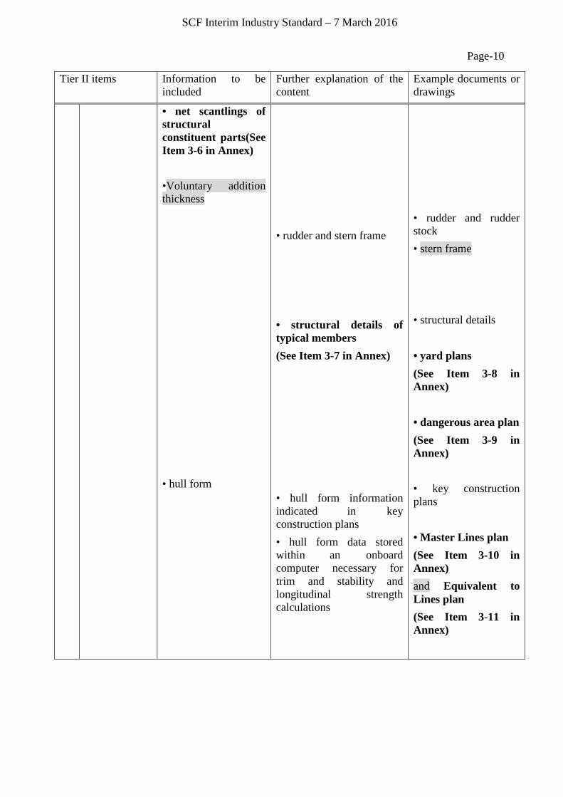
Page-10 Tier II items Information to be
included Further explanation of the content
Example documents or drawings
• net scantlings of structural constituent parts(See Item 3-6 in Annex) •Voluntary addition thickness • hull form
• rudder and stern frame • structural details of typical members (See Item 3-7 in Annex) • hull form information indicated in key construction plans • hull form data stored within an onboard computer necessary for trim and stability and longitudinal strength calculations
• rudder and rudder stock • stern frame • structural details • yard plans (See Item 3-8 in Annex) • dangerous area plan (See Item 3-9 in Annex) • key construction plans • Master Lines plan (See Item 3-10 in Annex) and Equivalent to Lines plan (See Item 3-11 in Annex)

SCF Interim Industry Standard – 7 March 2016
Page-11 Tier II items Information to be
included Further explanation of the content
Example documents or drawings
4. Fatigue life • applied Rule (date and revision) • applied alternative to Rule • calculating conditions and results; • assumed loading conditions • fatigue life calculation results
• applied design method alternative to Rule and subject structure(s) • assumed loading conditions and rates • bulky output of fatigue life calculation (See Item 4-1 in Annex) • plan showing areas prone to fatigue (See Item 4-2 in Annex)
• List of Applied Rules & Standards and General Information on SCF • structural details • full detailed fatigue life calculation • areas prone to fatigue
5. Residual strength
• applied Rule (date and revision) •Calculating conditions and results
• bulky output of strength calculation
• List of Applied Rules & Standards and General Information on SCF • damage control plan • full detailed strength calculation
6. Protection against corrosion 6.1 Coating life • coated areas and
target coating life and other measures for corrosion protection in holds, cargo and ballast tanks, other structure-integrated deep tanks and void spaces • specification for coating in holds, cargo and ballast tanks, other structure- integrated deep tanks and void spaces
• List of Applied Rules & Standards and General Information on SCF Coating Technical File required by PSPC
SCF Interim Industry Standard – 7 March 2016
Page-12 Tier II items Information to be
included Further explanation of the content
Example documents or drawings
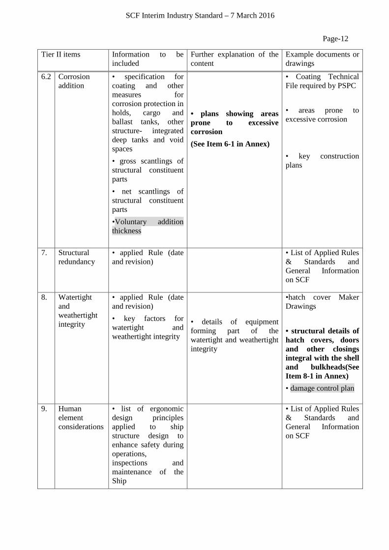
6.2
Corrosion addition
• specification for coating and other measures for corrosion protection in holds, cargo and ballast tanks, other structure- integrated deep tanks and void spaces • gross scantlings of structural constituent parts • net scantlings of structural constituent parts •Voluntary addition thickness
• plans showing areas prone to excessive corrosion (See Item 6-1 in Annex)
• Coating Technical File required by PSPC • areas prone to excessive corrosion • key construction plans
7. Structural redundancy
• applied Rule (date and revision)
• List of Applied Rules & Standards and General Information on SCF
8. Watertight and weathertight integrity
• applied Rule (date and revision) • key factors for watertight and weathertight integrity
• details of equipment forming part of the watertight and weathertight integrity
•hatch cover Maker Drawings • structural details of hatch covers, doors and other closings integral with the shell and bulkheads(See Item 8-1 in Annex) • damage control plan
9. Human element considerations
• list of ergonomic design principles applied to ship structure design to enhance safety during operations, inspections and maintenance of the Ship
• List of Applied Rules & Standards and General Information on SCF
SCF Interim Industry Standard – 7 March 2016
Page-13 Tier II items Information to be
included Further explanation of the content
Example documents or drawings
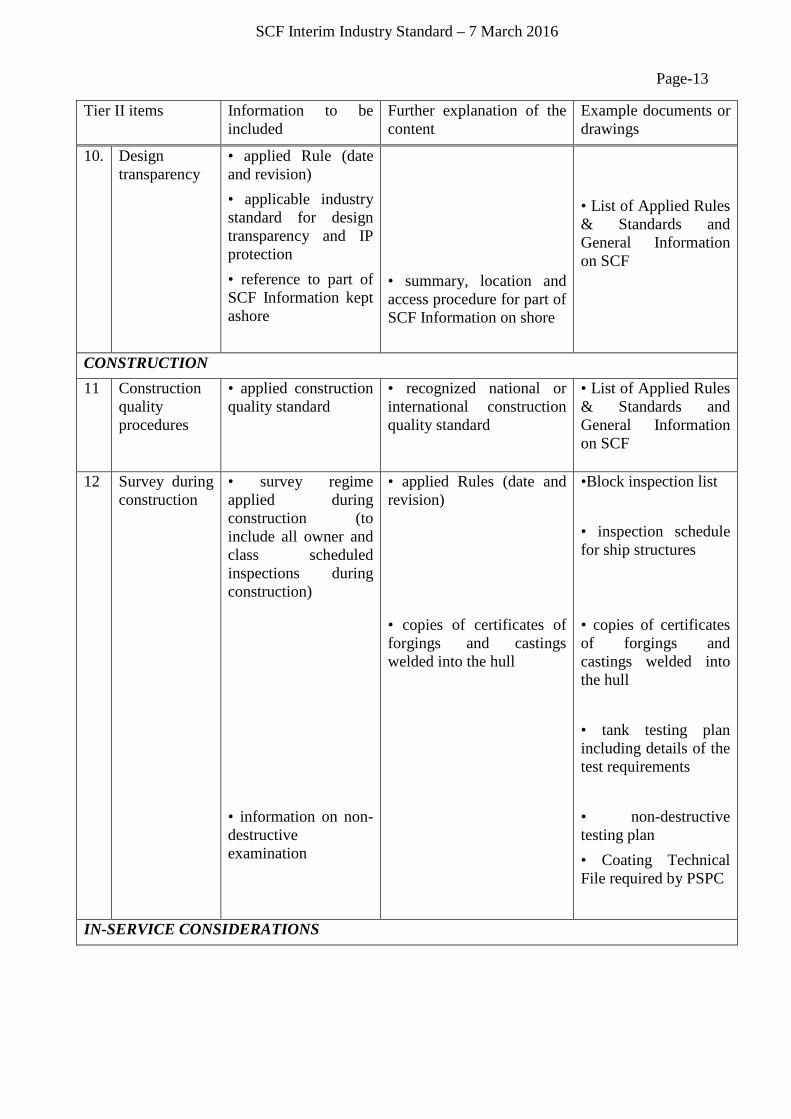
10. Design transparency
• applied Rule (date and revision) • applicable industry standard for design transparency and IP protection • reference to part of SCF Information kept ashore
• summary, location and access procedure for part of SCF Information on shore
• List of Applied Rules & Standards and General Information on SCF
CONSTRUCTION 11 Construction
quality procedures
• applied construction quality standard
• recognized national or international construction quality standard
• List of Applied Rules & Standards and General Information on SCF
12 Survey during construction
• survey regime applied during construction (to include all owner and class scheduled inspections during construction) • information on non-destructive examination
• applied Rules (date and revision) • copies of certificates of forgings and castings welded into the hull
•Block inspection list • inspection schedule for ship structures • copies of certificates of forgings and castings welded into the hull • tank testing plan including details of the test requirements • non-destructive testing plan • Coating Technical File required by PSPC
IN-SERVICE CONSIDERATIONS
SCF Interim Industry Standard – 7 March 2016
Page-14 Tier II items Information to be
included Further explanation of the content
Example documents or drawings
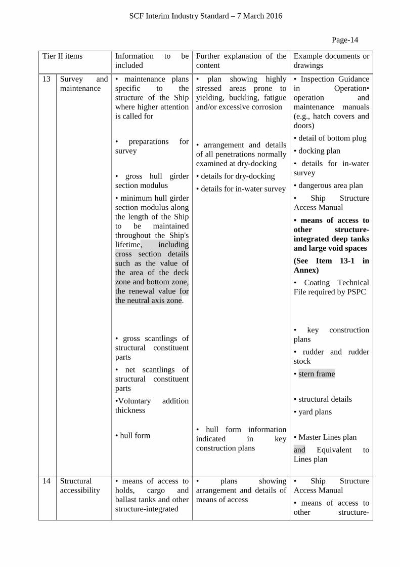
13 Survey and maintenance
• maintenance plans specific to the structure of the Ship where higher attention is called for • preparations for survey • gross hull girder section modulus • minimum hull girder section modulus along the length of the Ship to be maintained throughout the Ship's lifetime, including cross section details such as the value of the area of the deck zone and bottom zone, the renewal value for the neutral axis zone. • gross scantlings of structural constituent parts • net scantlings of structural constituent parts •Voluntary addition thickness • hull form
• plan showing highly stressed areas prone to yielding, buckling, fatigue and/or excessive corrosion • arrangement and details of all penetrations normally examined at dry-docking • details for dry-docking • details for in-water survey • hull form information indicated in key construction plans
• Inspection Guidance in Operation• operation and maintenance manuals (e.g., hatch covers and doors) • detail of bottom plug • docking plan • details for in-water survey • dangerous area plan • Ship Structure Access Manual • means of access to other structure-integrated deep tanks and large void spaces (See Item 13-1 in Annex) • Coating Technical File required by PSPC • key construction plans • rudder and rudder stock • stern frame • structural details • yard plans • Master Lines plan and Equivalent to Lines plan
14 Structural accessibility
• means of access to holds, cargo and ballast tanks and other structure-integrated
• plans showing arrangement and details of means of access
• Ship Structure Access Manual • means of access to other structure-
SCF Interim Industry Standard – 7 March 2016
Page-15 Tier II items Information to be
included Further explanation of the content
Example documents or drawings
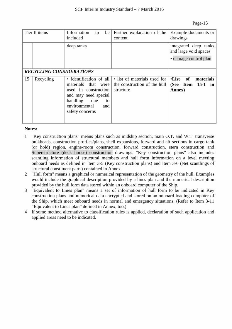
deep tanks
integrated deep tanks and large void spaces • damage control plan
RECYCLING CONSIDERATIONS 15 Recycling • identification of all
materials that were used in construction and may need special handling due to environmental and safety concerns
• list of materials used for the construction of the hull structure
•List of materials (See Item 15-1 in Annex)
Notes: 1 "Key construction plans" means plans such as midship section, main O.T. and W.T. transverse
bulkheads, construction profiles/plans, shell expansions, forward and aft sections in cargo tank (or hold) region, engine-room construction, forward construction, stern construction and Superstructure (deck house) construction drawings. “Key construction plans” also includes scantling information of structural members and hull form information on a level meeting onboard needs as defined in Item 3-5 (Key construction plans) and Item 3-6 (Net scantlings of structural constituent parts) contained in Annex.
2 "Hull form" means a graphical or numerical representation of the geometry of the hull. Examples would include the graphical description provided by a lines plan and the numerical description provided by the hull form data stored within an onboard computer of the Ship.
3 "Equivalent to Lines plan" means a set of information of hull form to be indicated in Key construction plans and numerical data encrypted and stored on an onboard loading computer of the Ship, which meet onboard needs in normal and emergency situations. (Refer to Item 3-11 “Equivalent to Lines plan” defined in Annex, too.)
4 If some method alternative to classification rules is applied, declaration of such application and applied areas need to be indicated.
SCF Interim Industry Standard – 7 March 2016
Page-16 2.3. IP Levels
The following two IP Levels are defined for SCF documents and drawings considering IP sensitivity, operational needs and standard access procedures:
• Ordinary IP Level • High IP Level
Standard IP Levels of SCF documents and drawings are shown along with standard storage locations in Table 2.
These standard IP Levels indicated in Table 2 may be modified for specific Ships subject to agreement between the Shipowner and IP-Holders concerned.
Storage locations indicated in Table 2 may be changed subject to agreement between the Shipowner and IP-Holder concerned. However, any item required to be on board by IMO Conventions, and those items listed as being on board in the table are to be on board as a minimum to ensure that they are transferred with the Ship whenever a change of Shipowner takes place.
All SCF Information will need appropriate care to be taken to safeguard the relevant IP.
2.4. Format of SCF Information
In order to facilitate both the use of the safety related information and the protection of IP, the SCF Onboard could be stored and used in different formats, e.g. either hardcopies or digital files (including a viewer/browser with printout functionality) at the choice of the Shipowner or in accordance with requirements of the Flag State and/or port States. A complete set of the SCF Onboard and SCF Supplement Ashore in a digital format is kept at the Archive Center.
Digital SCF documents need to be stored in a format (software and hardware) that ensures compatibility with standard hardware/software (standard PC operating systems) and that can be upgraded in the future to cater for IT technology advancement. Recognized global standards are expected to be used as far as practical so that there will be no critical access failure when hardware such as personal computers and/or software such as operating systems and browsers are updated or renewed, or when the Shipowner or the Archive Center is changed.
Regardless of the format of documents and drawings, the access to and safekeeping of SCF Information is performed in accordance with the principles provided in Ch. 3.2.
SCF Interim Industry Standard – 7 March 2016
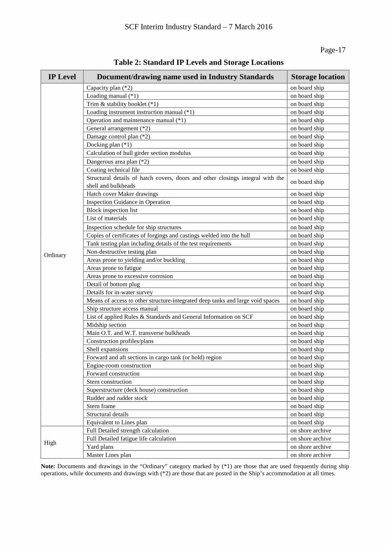
Page-17 Table 2: Standard IP Levels and Storage Locations
IP Level Document/drawing name used in Industry Standards Storage location
Ordinary
Capacity plan (*2) on board ship Loading manual (*1) on board ship Trim & stability booklet (*1) on board ship Loading instrument instruction manual (*1) on board ship Operation and maintenance manual (*1) on board ship General arrangement (*2) on board ship Damage control plan (*2) on board ship Docking plan (*1) on board ship Calculation of hull girder section modulus on board ship Dangerous area plan (*2) on board ship Coating technical file on board ship Structural details of hatch covers, doors and other closings integral with the shell and bulkheads on board ship
Hatch cover Maker drawings on board ship Inspection Guidance in Operation on board ship Block inspection list on board ship List of materials on board ship Inspection schedule for ship structures on board ship Copies of certificates of forgings and castings welded into the hull on board ship Tank testing plan including details of the test requirements on board ship Non-destructive testing plan on board ship Areas prone to yielding and/or buckling on board ship Areas prone to fatigue on board ship Areas prone to excessive corrosion on board ship Detail of bottom plug on board ship Details for in-water survey on board ship Means of access to other structure-integrated deep tanks and large void spaces on board ship Ship structure access manual on board ship List of applied Rules & Standards and General Information on SCF on board ship Midship section on board ship Main O.T. and W.T. transverse bulkheads on board ship Construction profiles/plans on board ship Shell expansions on board ship Forward and aft sections in cargo tank (or hold) region on board ship Engine-room construction on board ship Forward construction on board ship Stern construction on board ship Superstructure (deck house) construction on board ship Rudder and rudder stock on board ship Stern frame on board ship Structural details on board ship Equivalent to Lines plan on board ship
High
Full Detailed strength calculation on shore archive Full Detailed fatigue life calculation on shore archive Yard plans on shore archive Master Lines plan on shore archive
Note: Documents and drawings in the “Ordinary” category marked by (*1) are those that are used frequently during ship operations, while documents and drawings with (*2) are those that are posted in the Ship’s accommodation at all times.
SCF Interim Industry Standard – 7 March 2016
Page-18 3. Management of SCF Information
3.1. Preparation of SCF Information
Upon delivery of the newly built ship, the Shipbuilder – functioning as co-ordinator of all IP-Holders – provides SCF Information in accordance with the IMO requirements as described below:
i. The SCF Onboard to the Ship; ii. Copy of the SCF Onboard to the Shipowner’s Office Ashore; and
iii. Copy of the SCF Onboard and SCF Supplement Ashore to the Archive Center
3.2. Access and Safekeeping of SCF Information
Shipowner securely keeps SCF Information throughout the Ship’s operational lifetime in order to ensure safe operations of the Ship.
Shipowner, for Safe Operation Purposes, can access the SCF Information on board at any time and permit other Access Right Holders to access SCF Information through the Shipowner under the following principles:
• The IP of SCF Information including confidentiality needs to be protected; and • Appropriate procedures to manage access to and securely keep SCF Information in line with
the SCF IS need to be implemented by the Shipowner, e.g. as a part of the Quality Management Systems.
In principle, the applicable access and safekeeping procedures are to be:
i. strict enough to ensure IP protection; ii. simple enough for smooth access;
iii. robust enough for onboard utilization; iv. durable enough for lifetime service; v. compatible with standard hardware/software systems in the market; and
vi. cost effective.
The access and safekeeping procedures for each IP Level are as follows:
a) Ordinary IP Level information: the company document management system as a part of the Ship’s Quality Management System is expected to include procedures for access management (e.g., recording of name of document or drawing, access date, name of accessing person/organization and the existence of a confidentiality agreement between the IP Holder(s) and Shipowner needs to be recognized.) It is anticipated that appropriate IT security procedures to protect information held in electronic form are put in place. These include periodical renewal of passwords or equivalent and may include periodical renewal of the information to ensure that a complete set of the latest information is used and that the information has not been compromised.
b) High IP Level information: is stored at the Archive Center ashore. When the Shipowner initiates the procedures for access to the information, accompanied with information related to the uses of the information, the Archive Center, in accordance with the specific procedures, provides the required information after obtaining confirmation by the IP Holder. After the period of use, High IP Level information is to be returned to the Archive Center.
Hull form and structural strength information that is required for mandatory Emergency Response Services (ERS) can be kept by dedicated ERS providers if IPR protection
SCF Interim Industry Standard – 7 March 2016
Page-19 obligations are acknowledged by the provider such as by means of a confidentiality
agreement. The specific protection obligations and access procedures of the SCF IS may be modified to adapt to the needs of the ERS.
The full detailed strength and fatigue life calculation documents are available to the Shipowner during the design and construction period of the Ship, and can after the delivery of the Ship be provided to the Shipowner from the Archive Center for internal use subject to the requirement not to disclose to any Third Party unless specifically agreed by the IP-Holders. (refer to the Annex, Item 3-2 and Item 4-1)
In general, it is envisaged that a confidentiality agreement could be developed between the owner and the IP-Holder. Company procedures for SCF access management need to take account of such agreement.
3.3. Archive Center The Archive Center securely keeps SCF Information and arranges appropriate measures for access to and IP protection of SCF Information, in accordance with the principles shown in the SCF IS.
The Archive Center is operated in accordance with the following basic operational requirements. The Archive Center:
i. takes a nonpartisan stance; ii. provides services 24 hours and 365 days in accordance with a predetermined
operational plan in order to respond to any global and urgent requirement to provide SCF Information kept at the Archive Center;
iii. provides services at least in English; iv. makes and keeps secure backup copies of the digital documents it keeps; v. provides the information on necessary hardware and software, and on relevant software
updates/upgrades, so that accessing individual may access SCF Information kept at the Archive Center; and
vi. provides tools such as browser software to view SCF Information that should be compatible with standard PC operating systems.
The Archive Center provides the SCF Onboard Information after checking whether:
• the party that required Access to SCF Information is either the Shipowner or another registered Access Right Holder; and
• the party requesting the information has confirmed that the information is needed for the Ship’s Safe Operation Purposes.
Archive Center provides the SCF Supplement Information after checking whether:
• the party that required Access to SCF Information is the Shipowner or another registered Access Right Holder who is making access via the Shipowner;
• there is an agreement between Shipowner and IP-Holder; and • required SCF Information is necessary and sufficient for the purpose.
The Archive Center appointed by the IP-Holder, from accredited candidates at the time of new-building of the Ship, needs to be agreed with the Shipowner.
SCF Interim Industry Standard – 7 March 2016
Page-20 3.4. Update of SCF Information
The Shipowner, following any significant event including, for example, substantial repair, conversion or any major modification to the Ship structure that requires Update of the SCF Information, needs to arrange an Update of the SCF Information.
In such cases, SCF Information before the Update needs to be continuously retained without destruction or modification along with the updated SCF Information for traceability purposes.
The Shipowner may task the Archive Center to carry out procedures for Update as appropriate. Updated SCF Information needs to be stored at the same Archive Center that keeps the Ship’s original SCF Information.
3.5. Use of SCF Information for Purposes other than Safe Operation The Shipowner is expected to agree in advance with the IP-Holder when SCF Information is disclosed to a Third Party for purposes other than Safe Operation Purpose, noting that the definition of ‘safe operation’ includes maintenance, repair, inspection and emergency response.
4. Revision of the Interim Industry Standards
In the event that the IMO requirement is amended or a relevant issue concerning IT progress or use of this SCF IS arises and a proposal is made by any member of the cross industry group (see the Introduction for its definition) for the revision of this SCF IS, the cross industry group will consider the need for a revision to the SCF IS. Following agreement of such a need, this SCF IS may be revised as appropriate.
In addition it is anticipated that in the absence of significant issues arising, a general review will be initiated by the cross industry group within 24 months from 1 July 2016 to take account of experience gained in the initial use of this SCF IS.
References
[1] International Maritime Organization: Res. MSC 290(87) SOLAS II-1/3-10: Goal-based Ship Construction Standards for Bulk Carriers and Oil Tankers (2010)
[2] International Maritime Organization: Res. MSC 287(87): Adoption of the International Goal-based Ship Construction Standards for Bulk Carriers and Oil Tankers (2010)
[3] International Maritime Organization: Res. MSC 296(87): Adoption of the Guidelines for Verification of Conformity with Goal-based Ship Construction Standards for Bulk Carriers and Oil Tankers (2010)
[4] International Maritime Organization: MSC.1/Circ.1343: Guidelines for the Information to be included in a Ship Construction File (2010)
[5] International Maritime Organization: MSC/Circ.1135: As-built Construction Drawings to be Maintained on Board the Ship and Ashore, 15 December (2004)

SCF Interim Industry Standard – 7 March 2016
Page-21 Annex Practical Guidelines for SCF Information Definition
A.1 Introduction
(1) Purpose and notes
- This Annex shows a collection of detailed definitions, models and examples of SCF Information which is based on the requirements of the IMO. The purpose of the detailed definitions, models and examples of SCF Information is to provide practical clarification and explanation on the "List of information to be included in the Ship Construction File (SCF)" indicated in Table 1 of Chapter 2 so as to prevent misinterpretation and confusion.
- Items with detailed definitions, models and examples are indicated by markers such as Items 1-1 to 15-1 in Table 1 of Chapter 2. In general, detailed definitions, models and examples are given on one page for each item. It should be noted that the set of SCF documents and drawings, models and examples given to each document/drawing are only for a specific design case, and different set of documents and drawings are acceptable as long as they include sufficient information conforming to requirements of SCF Information as a whole.
(2) Additional definitions
- Substantial repair: Steel replacement of the hull area of Ship affected by an accident (damage caused by contact, collision or grounding, etc.) or substantial corrosion.
- Any modification of the Ship structure: Scantling or shape change of original ship structure, or the addition of local reinforcements due to the installation of new equipment on board, etc.
- Updated SCF: Depending on Shipowner's decision, the Shipyard for repair/conversion updates the key construction plans or provides new sheets in relation with the modification which are additional to the existing key construction plans. Updated key construction plans or new sheets as well as relevant yard plans (fabrication and installation drawings) in a digital format are also provided as addition to SCF Supplement Ashore by the Shipyard for repair/conversion.
A.2 List of Applied Rules & Standards and General Information on SCF
“List of Applied Rules & Standards and General Information on SCF” means the information listed hereunder. However, IP-Holder may divide such information into SCF document(s) or provide such information in SCF drawing(s). IP-Holder may also compile following information into one document as part of SCF Onboard:
1) Applied Rules and Standards 2) List of SCF Onboard Information: Documents and drawings that constitute SCF Onboard of the
Ship need to be listed. 3) Table showing the storage location, IP Level and IP-Holder name for each of the SCF
documents or drawings containing SCF Information. 4) Table showing the linkage between each of the documents and drawings containing SCF
Information and the GBS Tier II functional requirements. 5) List of the documents and drawings kept at the Archive Center as SCF Supplement. 6) Location of the Archive Center and access information including contact points. 7) Procedures for updating SCF Information 8) The IS and SG including Intellectual property provisions.

SCF Interim Industry Standard – 7 March 2016
Page-22 Item 1-1: Applied Rules & Standards
Definition
- This document shows the names and versions of applied rules and standards as required by GBS.
- However, IP-Holder may divide such information and indicate in relevant SCF document(s) or drawing(s).
Models &
Examples (Information List)
Remarks
- The models and examples attached in this document are only for a specific design case, and different set of documents are acceptable as long as they include necessary information conforming to SCF requirements as a whole.
SCF items Information
1 Design life Design lifeA design life of 25 years is assumed for selecting ship design parameters. The specified design life is thenominal period that the ship is assumed to be exposed to operating conditions.
2Environmental
conditionsEnvironmental
conditions
Applied rules : Common Structural Rules for Bulk Carriers and Oil Tankers (DD MM YY)
Assumed environmental condition :
(North Atlantic wave environment)The rule requirements are based on a ship trading in the North Atlantic wave environment for its entire designlife.(Wind and current)The effects of wind and current with regard to the strength of the structure are not considered.(Ice)The effects of ice and ice accretion are not taken into account by the Rules.(Design temperatures)The Rules assume that the structural assessment of hull strength members is valid for the following designtemperatures: • Lowest mean daily average temperature in air is -10°C. • Lowest mean daily average temperature in seawater is 0°C.Ships intended to operate in areas with lower mean daily average temperature, e.g. regular service during winterseasons to Arctic or Antarctic waters are subject to the requirements as specified by the Society.In the above, the following definitions apply: Mean : Statistical mean over observation period (at least 20 years). Daily Average : Average during one day and night. Lowest : Lowest during year.For seasonally restricted service the lowest value within the period of operation applies.(Thermal loads)The effects of thermal loads and residual stresses are not taken into account in the Rules.
3Structuralstrength
General design
Applied rules : Common Structural Rules for Bulk Carriers and Oil TankerCalculating software : ClassNK PrimeShip-HULL(Rules)(DSA) Ver.○.○.○
Details of strength calculations are included in "Calculation sheet of Hull Strength".
4 Fatigue life Fatigue life
Applied rules : Common Structural Rules for Bulk Carriers and Oil Tankers (DD MM YY)Calculating software : ClassNK PrimeShip-HULL(Rules)(DSA) Ver.○.○.○
Details of fatigue life calculations are included in full "Detailed fatigue life calculation".
5Residualstrength
Residualstrength
Applied rules : Common Structural Rules for Bulk Carriers and Oil Tankers (DD MM YY)Calculating software : ClassNK PrimeShip-HULL(Rules)(DSA) Ver.○.○.○
Details of strength calculations are included in full "Detailed strength calculation".
6Protection
againstcorrosion
Coating life Coating specifications are included in "Painting Schedule" and "Coating Technical File".
7Structural
redundancyStructural
redundancy
Applied rules : Common Structural Rules for Bulk Carriers and Oil Tankers (DD MM YY)Calculating software : ClassNK PrimeShip-HULL(Rules)(DSA) Ver.○.○.○
Details of strength calculations are included in full "Detailed strength calculation".
9Human elementconsiderations
Human elementconsiderations
Applied rules : Common Structural Rules for Bulk Carriers and Oil Tankers (DD MM YY)
10Design
transparencyDesign
transparencyApplied rules : Common Structural Rules for Bulk Carriers and Oil Tankers (DD MM YY)Applied industry standard : SCF Industry Standard & Unified Interpretation
11Construction
qualityprocedures
Constructionquality
proceduresApplied construction quality standard : Japan Shipbuilding Quality Standard Ver.○.○.○
GBS TierⅡitems
SCF Interim Industry Standard – 7 March 2016
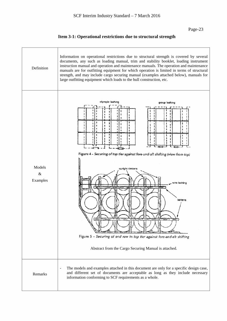
Page-23 Item 3-1: Operational restrictions due to structural strength
Definition
Information on operational restrictions due to structural strength is covered by several documents, any such as loading manual, trim and stability booklet, loading instrument instruction manual and operation and maintenance manuals. The operation and maintenance manuals are for outfitting equipment for which operation is limited in terms of structural strength, and may include cargo securing manual (examples attached below), manuals for large outfitting equipment which loads to the hull construction, etc.
Models &
Examples
Abstract from the Cargo Securing Manual is attached.
Remarks
- The models and examples attached in this document are only for a specific design case,
and different set of documents are acceptable as long as they include necessary information conforming to SCF requirements as a whole.
SCF Interim Industry Standard – 7 March 2016
Page-24
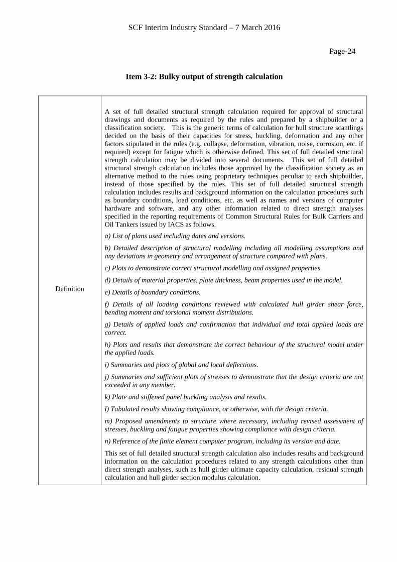
Item 3-2: Bulky output of strength calculation
Definition
A set of full detailed structural strength calculation required for approval of structural drawings and documents as required by the rules and prepared by a shipbuilder or a classification society. This is the generic terms of calculation for hull structure scantlings decided on the basis of their capacities for stress, buckling, deformation and any other factors stipulated in the rules (e.g. collapse, deformation, vibration, noise, corrosion, etc. if required) except for fatigue which is otherwise defined. This set of full detailed structural strength calculation may be divided into several documents. This set of full detailed structural strength calculation includes those approved by the classification society as an alternative method to the rules using proprietary techniques peculiar to each shipbuilder, instead of those specified by the rules. This set of full detailed structural strength calculation includes results and background information on the calculation procedures such as boundary conditions, load conditions, etc. as well as names and versions of computer hardware and software, and any other information related to direct strength analyses specified in the reporting requirements of Common Structural Rules for Bulk Carriers and Oil Tankers issued by IACS as follows. a) List of plans used including dates and versions.
b) Detailed description of structural modelling including all modelling assumptions and any deviations in geometry and arrangement of structure compared with plans.
c) Plots to demonstrate correct structural modelling and assigned properties.
d) Details of material properties, plate thickness, beam properties used in the model.
e) Details of boundary conditions.
f) Details of all loading conditions reviewed with calculated hull girder shear force, bending moment and torsional moment distributions.
g) Details of applied loads and confirmation that individual and total applied loads are correct.
h) Plots and results that demonstrate the correct behaviour of the structural model under the applied loads.
i) Summaries and plots of global and local deflections.
j) Summaries and sufficient plots of stresses to demonstrate that the design criteria are not exceeded in any member.
k) Plate and stiffened panel buckling analysis and results.
l) Tabulated results showing compliance, or otherwise, with the design criteria.
m) Proposed amendments to structure where necessary, including revised assessment of stresses, buckling and fatigue properties showing compliance with design criteria.
n) Reference of the finite element computer program, including its version and date.
This set of full detailed structural strength calculation also includes results and background information on the calculation procedures related to any strength calculations other than direct strength analyses, such as hull girder ultimate capacity calculation, residual strength calculation and hull girder section modulus calculation.

SCF Interim Industry Standard – 7 March 2016
Page-25
Models &
Examples
Results of Finite Element Analysis
Remarks
- Full detailed structural strength calculation is available to the Shipowner during the construction period, with the Shipowner procedurally complying with the IP protection principles, similar to those stated in the Introduction and chapter 3 of the SCF IS (similar in the sense that the SCF IS descriptions are primarily for actions taking place after delivery of the ship).
- It is standard to store such detailed structural strength calculation only at the Archive Center from the viewpoint of protection of Intellectual Property Rights.
- The models and examples attached in this document are only for a specific design case, and different set of documents are acceptable as long as they include necessary information conforming to SCF requirements as a whole.

SCF Interim Industry Standard – 7 March 2016
Page-26 Item 3-3: Plan showing highly stressed areas prone to yielding and/or buckling
Definition
This plan is used for proper and preventive inspections and surveys during construction and after the delivery of the Ship, and indicates each specific area for the Ship as "areas without margin more than a certain degree". In addition to the above, areas where general caution is advised may be included.
Models &
Examples
Trans. Ring Section
Horizontal Stringer Plan
Figure: Typical plan showing higly stressed areas prone to yielding and/or buckling for
Double Hull Oil Tanker (Note) Highly stressed areas prone to yielding and/or buckling are shown by the following marks:
Remarks
- Background of this subject is the cautionary statement below in the Tier I Goal of GBS: "Ships shall be designed and constructed for a specified design life to be safe and environmentally friendly, when properly operated and maintained under the specified operating and environmental conditions"
- "Specified design life is the nominal period that the ship is assumed to be exposed to operating and/or environmental conditions and/or the corrosive environment and is used for selecting appropriate ship design parameters. However, the ship's actual service life may be longer or shorter depending on the actual operating conditions and maintenance of the ship throughout its life cycle."
- Acceptance criteria by classification society for yielding and buckling of all structural members are satisfied as a matter of course (see Item 3-2).
- The models and examples attached in this document are only for a specific design case, and different set of documents are acceptable as long as they include necessary information conforming to SCF requirements as a whole.
SCF Interim Industry Standard – 7 March 2016
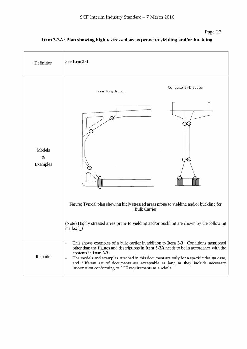
Page-27 Item 3-3A: Plan showing highly stressed areas prone to yielding and/or buckling
Definition
See Item 3-3
Models &
Examples
Figure: Typical plan showing higly stressed areas prone to yielding and/or buckling for Bulk Carrier
(Note) Highly stressed areas prone to yielding and/or buckling are shown by the following marks:
Remarks
- This shows examples of a bulk carrier in addition to Item 3-3. Conditions mentioned other than the figures and descriptions in Item 3-3A needs to be in accordance with the contents in Item 3-3.
- The models and examples attached in this document are only for a specific design case, and different set of documents are acceptable as long as they include necessary information conforming to SCF requirements as a whole.

SCF Interim Industry Standard – 7 March 2016
Page-28 Item 3-4: Structural drawings
Definition
1.A collection of drawings for structural members composing main hull 2.Including scantlings (as-built, net) of all structural members of the main hull 3.Including information on leg length of welds 4. Composed of following figures. (1) key construction plans See Item 3-5. (2) yard plans See Item 3-8. 5. Describing method for gross and net scantlings See Item 3-6. 6. Describing method for weld leg length See Item 3-8. 7. Explanation of abbreviated symbols Abbreviated symbols used for above SCF Information need to be explained in the drawings
or in a separate drawing. Explanation of symbols not related to SCF Information (for instance, information provided
by the shipbuilder for construction) is not necessary. 8. Examples of figures Key construction plans: See Item 3-5. Yard plans: See Item 3-8.
Models &
Examples
Remarks
- The models and examples attached in this document are only for a specific design case,
and different set of documents are acceptable as long as they include necessary information conforming to SCF requirements as a whole.

SCF Interim Industry Standard – 7 March 2016
Page-29 Item 3-5: Key construction plan
Definition
A set of plans (drawings) showing shapes and gross scantlings of major structural members required mainly for classification approval, including superstructure construction.
Models &
Examples
- Key construction plans are composed of the following set of drawings described in the explanatory note 2 of MSC.1/Circ.1343.
+midship section +main O.T. and W.T. transverse bulkheads +construction profiles/plans +shell expansions +forward and aft section in cargo tank (or hold) region +engine-room construction +forward construction +stern construction +superstructure (deck house) construction
Example of a key construction plan
Remarks
- Leg length of welds may be included in separate drawings. - Detailed structure may be included in separate drawings as "structural details”. Refer
to Item 3-6. - Hull form information should also be shown in cross section, plan and profile on a
sufficient level meeting onboard needs. - Abbreviated symbols used for SCF Information need to be explained in the drawings or
in a separate drawing. - Explanation of abbreviated symbols not related to SCF Information (for instance,
information provided by the shipbuilder for construction) is not necessary. - The models and examples attached in this document are only for a specific design case,
and different set of documents are acceptable as long as they include necessary information conforming to SCF requirements as a whole
SCF Interim Industry Standard – 7 March 2016
Page-30 Item 3-6: Net scantlings of structural constituent parts
Definition
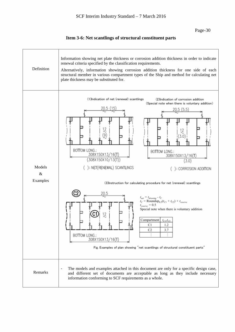
Information showing net plate thickness or corrosion addition thickness in order to indicate renewal criteria specified by the classification requirements. Alternatively, information showing corrosion addition thickness for one side of each structural member in various compartment types of the Ship and method for calculating net plate thickness may be substituted for.
Models &
Examples
Remarks
- The models and examples attached in this document are only for a specific design case,
and different set of documents are acceptable as long as they include necessary information conforming to SCF requirements as a whole.
SCF Interim Industry Standard – 7 March 2016
Page-31 Item 3-7: Structural details of typical members
Definition
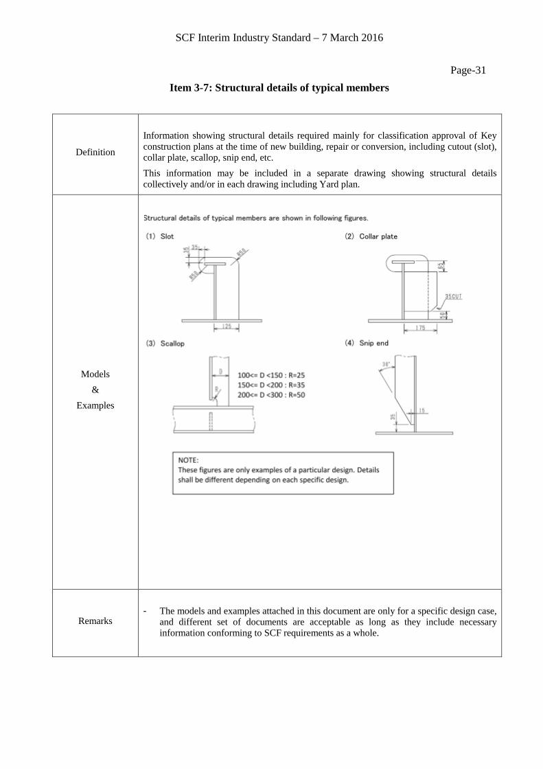
Information showing structural details required mainly for classification approval of Key construction plans at the time of new building, repair or conversion, including cutout (slot), collar plate, scallop, snip end, etc. This information may be included in a separate drawing showing structural details collectively and/or in each drawing including Yard plan.
Models &
Examples
Remarks
- The models and examples attached in this document are only for a specific design case,
and different set of documents are acceptable as long as they include necessary information conforming to SCF requirements as a whole.
SCF Interim Industry Standard – 7 March 2016
Page-32 Item 3-8: Yard plans
Definition
A set of plans (drawings) containing scantling information of all structural members of the Ship. The size, thickness, grade and continuity of structural members including weld property are shown. If the key construction plans include scantling information of all structural members, they can be substituted for yard plans, however, need to be kept as a part of SCF Onboard.
Models &
Examples
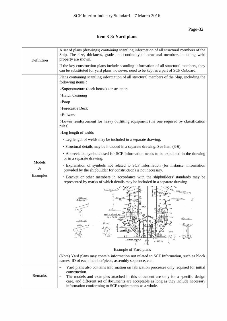
Plans containing scantling information of all structural members of the Ship, including the following items:
○Superstructure (deck house) construction ○Hatch Coaming ○Poop ○Forecastle Deck ○Bulwark ○Lower reinforcement for heavy outfitting equipment (the one required by classification rules) ○Leg length of welds
・Leg length of welds may be included in a separate drawing.
・Structural details may be included in a separate drawing. See Item (3-6).
・Abbreviated symbols used for SCF Information needs to be explained in the drawing or in a separate drawing.
・Explanation of symbols not related to SCF Information (for instance, information provided by the shipbuilder for construction) is not necessary.
・Bracket or other members in accordance with the shipbuilders' standards may be represented by marks of which details may be included in a separate drawing.
Example of Yard plans
(Note) Yard plans may contain information not related to SCF Information, such as block names, ID of each member/piece, assembly sequence, etc.
Remarks
- Yard plans also contains information on fabrication processes only required for initial construction.
- The models and examples attached in this document are only for a specific design case, and different set of documents are acceptable as long as they include necessary information conforming to SCF requirements as a whole.

SCF Interim Industry Standard – 7 March 2016
Page-33 Item 3-9: Dangerous area plan
Definition Drawing showing dangerous areas of the Ship which are defined in IEC 60092-502 Electrical installation in ships Part 502 Tankers-Special features. Applicable to oil tankers only.
Models &
Examples
Remarks - The models and examples attached in this document are only for a specific design case,
and different set of documents are acceptable as long as they include necessary information conforming to SCF requirements as a whole.

SCF Interim Industry Standard – 7 March 2016
Page-34 Item 3-10: Master Lines plan
Definition A Master Lines plan is dedicated to show detailed hull form of the Ship entirely.
Models &
Examples
Body plan (Aft) Body plan (Fore) (Station lines) (Station lines)
Forward part of half breadth and sheer plans
(Water lines and buttock lines)
Aft part of half breadth and sheer plans
(Water lines and buttock lines) (Note) Reproduced from the Report of the Shipping Research Association of Japan, the 154th Research Committee, (Research material No.235), March 1977, with the permission by Japan Ship Technology Research Association (JSTRA)
Remarks
- The models and examples attached in this document are only for a specific design case,
and different set of documents are acceptable as long as they include necessary information conforming to SCF requirements as a whole.
SCF Interim Industry Standard – 7 March 2016
Page-35 Item 3-11: Equivalent to Lines plan
Definition
"Equivalent to Lines plan" means graphical and/or numerical information of the geometry of the hull form needed for onboard repair of any part of the hull structure and/or trim & stability and longitudinal strength calculation needed routinely or in emergency situations onboard. It is provided by set of information of hull form to be indicated in Key construction plans and numerical data encrypted and stored on an onboard loading computer of the Ship.
Models &
Examples
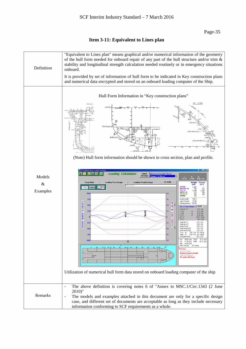
Hull Form Information in “Key construction plans”
(Note) Hull form information should be shown in cross section, plan and profile.
Utilization of numerical hull form data stored on onboard loading computer of the ship
Remarks
- The above definition is covering notes 6 of "Annex to MSC.1/Circ.1343 (2 June 2010)"
- The models and examples attached in this document are only for a specific design case, and different set of documents are acceptable as long as they include necessary information conforming to SCF requirements as a whole.
SCF Interim Industry Standard – 7 March 2016
Page-36 Item 4-1: Bulky output of fatigue life calculation
Definition
A set of full detailed fatigue strength calculation required for approval of structural drawings and documents as required by the rules and prepared by a shipbuilder or a classification society. This set of full detailed fatigue life calculation may be divided into several documents. This set of full detailed fatigue life calculation includes those approved by the classification society as an alternative method to the rules using proprietary techniques peculiar to each shipbuilder, instead of those specified by the rules. This set of full detailed fatigue life calculation includes results and background information on the calculation procedures such as boundary conditions, load conditions, etc. as well as names and versions of computer hardware and software, and any other information related to direct fatigue life analyses specified in the reporting requirements of Common Structural Rules for Bulk Carriers and Oil Tankers issued by IACS as follows. a) List of plans used including dates and versions.
b) Detailed description of structural modelling including all modelling assumptions and any deviations in geometry and arrangement of structure compared with plans.
c) Plots to demonstrate correct structural modelling and assigned properties.
d) Details of material properties, plate thickness, beam properties used in the model.
e) Details of boundary conditions.
f) Details of all loading conditions reviewed with calculated hull girder shear force, bending moment and torsional moment distributions.
g) Details of applied loads and confirmation that individual and total applied loads are correct.
h) Plots and results that demonstrate the correct behaviour of the structural model under the applied loads.
i) Summaries and plots of global and local deflections.
j) Summaries and sufficient plots of stresses to demonstrate that the design criteria are not exceeded in any member.
k) Plate and stiffened panel buckling analysis and results.
l) Tabulated results showing compliance, or otherwise, with the design criteria.
m) Proposed amendments to structure where necessary, including revised assessment of stresses, buckling and fatigue properties showing compliance with design criteria.
n) Reference of the finite element computer program, including its version and date.
This set of full detailed fatigue life calculation also includes results and background information on the calculation procedures related to any fatigue life calculations other than direct fatigue life analyses, such as simplified fatigue life calculations.
SCF Interim Industry Standard – 7 March 2016
Page-37
Models &
Examples
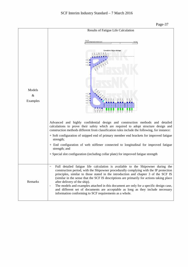
Results of Fatigue Life Calculation
Advanced and highly confidential design and construction methods and detailed calculations to prove their safety which are required to adopt structure design and construction methods different from classification rules include the following, for instance: + Soft configuration of snipped end of primary member end brackets for improved fatigue
strength; + End configuration of web stiffener connected to longitudinal for improved fatigue
strength; and + Special slot configuration (including collar plate) for improved fatigue strength
Remarks
- Full detailed fatigue life calculation is available to the Shipowner during the construction period, with the Shipowner procedurally complying with the IP protection principles, similar to those stated in the introduction and chapter 3 of the SCF IS (similar in the sense that the SCF IS descriptions are primarily for actions taking place after delivery of the ship).
- The models and examples attached in this document are only for a specific design case, and different set of documents are acceptable as long as they include necessary information conforming to SCF requirements as a whole.
SCF Interim Industry Standard – 7 March 2016
Page-38 Item 4-2: Plan showing areas prone to fatigue
Definition
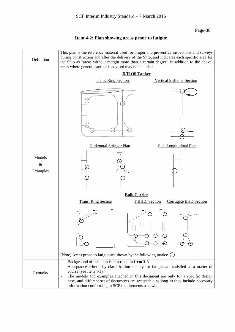
This plan is the reference material used for proper and preventive inspections and surveys during construction and after the delivery of the Ship, and indicates each specific area for the Ship as "areas without margin more than a certain degree" In addition to the above, areas where general caution is advised may be included.
Models &
Examples
D/H Oil Tanker Trans. Ring Section Vertical Stiffener Section
Horizontal Stringer Plan Side Longitudinal Plan
Bulk Carrier
Trans. Ring Section T.BHD. Section Corrugate BHD Section
(Note) Areas prone to fatigue are shown by the following marks:
Remarks
- Background of this item is described in Item 3-3. - Acceptance criteria by classification society for fatigue are satisfied as a matter of
course (see Item 4-1). - The models and examples attached in this document are only for a specific design
case, and different set of documents are acceptable as long as they include necessary information conforming to SCF requirements as a whole.
SCF Interim Industry Standard – 7 March 2016
Page-39 Item 6-1: Plan showing areas prone to excessive corrosion
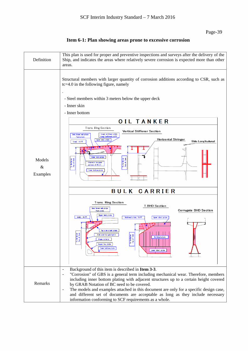
Definition This plan is used for proper and preventive inspections and surveys after the delivery of the Ship, and indicates the areas where relatively severe corrosion is expected more than other areas.
Models &
Examples
Structural members with larger quantity of corrosion additions according to CSR, such as tc=4.0 in the following figure, namely . - Steel members within 3 meters below the upper deck - Inner skin - Inner bottom
Remarks
- Background of this item is described in Item 3-3. - "Corrosion" of GBS is a general term including mechanical wear. Therefore, members
including inner bottom plating with adjacent structures up to a certain height covered by GRAB Notation of BC need to be covered.
- The models and examples attached in this document are only for a specific design case, and different set of documents are acceptable as long as they include necessary information conforming to SCF requirements as a whole.
SCF Interim Industry Standard – 7 March 2016
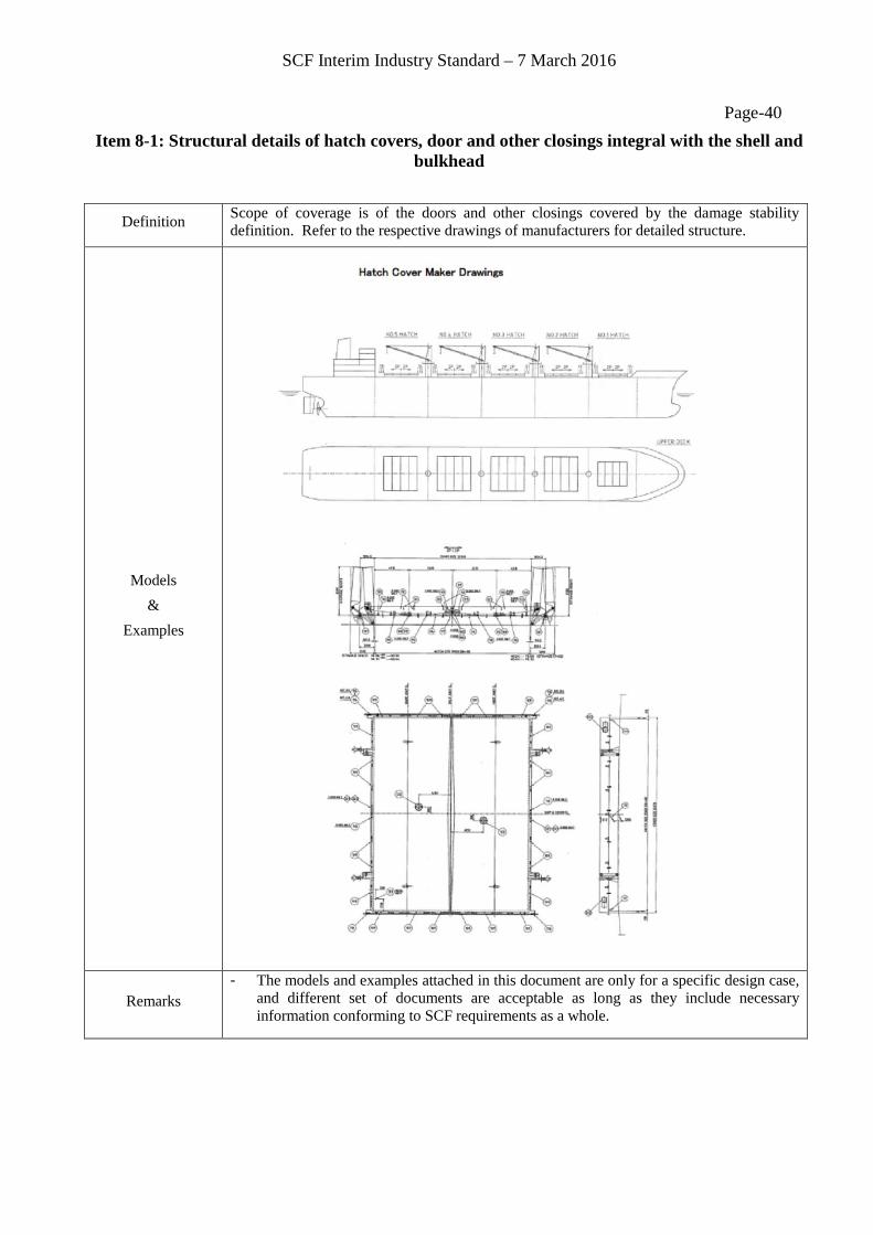
Page-40 Item 8-1: Structural details of hatch covers, door and other closings integral with the shell and
bulkhead
Definition Scope of coverage is of the doors and other closings covered by the damage stability definition. Refer to the respective drawings of manufacturers for detailed structure.
Models &
Examples
Remarks - The models and examples attached in this document are only for a specific design case,
and different set of documents are acceptable as long as they include necessary information conforming to SCF requirements as a whole.
SCF Interim Industry Standard – 7 March 2016
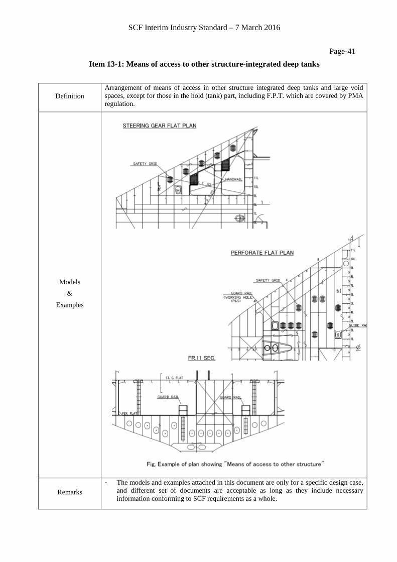
Page-41 Item 13-1: Means of access to other structure-integrated deep tanks
Definition Arrangement of means of access in other structure integrated deep tanks and large void spaces, except for those in the hold (tank) part, including F.P.T. which are covered by PMA regulation.
Models &
Examples
Remarks - The models and examples attached in this document are only for a specific design case,
and different set of documents are acceptable as long as they include necessary information conforming to SCF requirements as a whole.

SCF Interim Industry Standard – 7 March 2016
Page-42 Item 15-1: List of materials
Definition List of materials used for the hull structure.
Models &
Examples
Remarks
- The models and examples attached in this document are only for a specific design case,
and different set of documents are acceptable as long as they include necessary information conforming to SCF requirements as a whole.