the simple plair n flap used in other tail-first designs...
TRANSCRIPT
By Don Hewes (EAA 32101)12 Meadow Drive
Newport News, VA 23606
IN THE FIRST installment of this 3 part article, we discussedprimarily aerodynamic characteristics that could influence theflight behavior of tail-first airplanes when they encounter someform of contamination; that is, rain, snow, frost, bugs, dirt orwhat have you. The term "Flight Behavior Change" or "FBC"was coined to identify this influence. This month we will lookspecifically at some pertinent wind tunnel and flight test dataobtained by NASA using the VariEze airplane and relate thesefindings to our previous discussions of FBC and to the behaviorof several other current tail-first designs. We will also discussvarious design, construction and operational factors that can havesome significant effect on FBC.
Before proceeding, however, I would like to restate what I saidpreviously: that the VariEze was selected by NASA because itincorporated a number of unique and interesting advanced designfeatures and NOT because it has some particular problem. Thedata were used for this article because they were the only dataavailable pertinent to the subject of this article. The specific dataapplies only to the VariEze design and should not be applied tothe other designs without proper consideration being given to thephysical differences. However, some of the trends and effects notedcan be applied in a more or less straight forward manner as willbe discussed in this installment.
Wind Tunnel Data For VariEze Tail SurfaceIn the first installment we focused our attention on the critical
nature of the tail surface, so let's examine this further by lookingat the NASA wind tunnel data obtained from Reference 1 for theVariEze's tail surface. Figure 5 shows how the lift of the tail andthe complete airplane varies in the wind tunnel as the angle ofattack of the airplane is varied with the elevator set at severaldeflections for the clean or uncontaminated condition. (These datafor the tail are given in terms of the area of the main wing and,consequently, have smaller values than you would normally ex-pect to see. The difference between the two curves represents thelift contribution of the wing and the fuselage combination.)
Note that the increments of tail lift produced by deflection ofthe elevator (the spacing between the tail lift curves) decrease asthe elevator is deflected further and further downward. This isespecially evident for angles of attack above about 10°. Also, notethat the canard begins to stall at about 14° with zero deflectionBUT it begins at about 8° with maximum down deflection. Thus,DOWNWARD deflection of the elevator REDUCES THE LIFTEFFECTIVENESS OF THE ELEVATOR AND CAUSES EAR-LIER STALL of the complete canard surface. Bear in mind thatthis surface uses a slotted flap as the elevator which generally ismore effective in generating lift increments with deflection than48 JUNE 1983
the simpler plain flap used in other tail-first designs. The generaltrends in the data as illustrated here should be fairly similar,however.
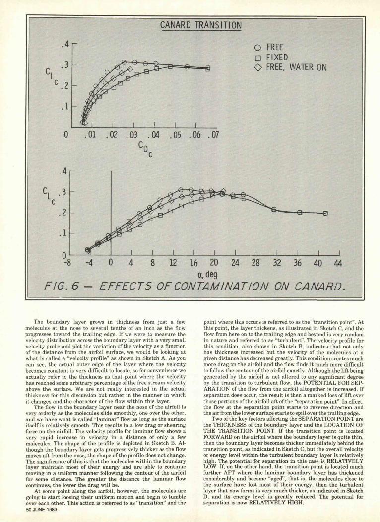
In Figure 6, three sets of data are shown, one for the tail witha dry smooth surface (FREE), one with the leading edges artifi-cially roughened with a small amount of coarse grit glued to bothleft and right tail panels (FIXED), and the last with both panelssmooth but with one panel wetted with water sprayed from nozzlesto simulate rain (FREE, WATER ON). The elevator deflection iszero for all cases. (The terms "free" and "fixed" refer to the typesof air flow transition associated with the smooth and roughenedleading edges.)
There is a LOSS OF ABOUT 27% of the TAIL LIFT through-out the normal flight range of angles of attack for the secondset of data compared with the first set showing that the ap-plication of the coarse grit, representing a "bad case of thebugs", had a very pronounced effect on the aerodynamic charac-teristics of the canard. The loss of lift produced by the WATERSPRAY IS ROUGHLY EQUIVALENT TO THAT OF THE GRITwhen you consider that only half of the canard was sprayed withwater. There are also corresponding increases in the drag of thecanard associated with these losses of life.
These are very large changes in the aerodynamic characteris-tics and certainly indicate a significant effect of contaminationon the characteristics of the tail surface. (Remember, however,we are looking only at the tail contribution and not the total aerocharacteristics of the airplane.) Of course, the influence of surfacecontamination on the drag of sailplanes has been recognized formany years and is associated with the premature TRANSITIONfrom laminar to turbulent flow which causes the drag to increasesignificantly but does not alter the lift to any extent at cruiseconditions. The somewhat unusual aspect of these data is therelatively large loss of lift at the low angles of attack due to theroughness but this type of loss can be found with some otherairfoils that are unusually thick. The loss is attributed to prema-ture turbulent flow SEPARATION near the trailing edge occur-ring at the lower angles of attack.
The trends noted in the data do correspond to those assumedin our earlier discussions, however, we are missing elevator hingemoment data which unfortunately were not available.
Discussion of Tail Sensitivity to ContaminationWhat is it that makes the tail aerodynamics so sensitive to
the effect of rain and bugs? The quick answer to this question isthat it is the particular type of airfoil that is being used for thetail surface and is not the location of the surface on the airplane.But this needs explanation.
As air flows past an airfoil, the molecules of air next to thesurface are slowed by the frictional forces acting between themolecules and the airfoil surface as well as the molecules them-selves. This action forms what is referred to as a boundary layeron both the top and lower surfaces. We will concern ourselveswith the layer over the upper surface. This boundary layer andwhat happens to it are the key factors to the FBC phenomenon.
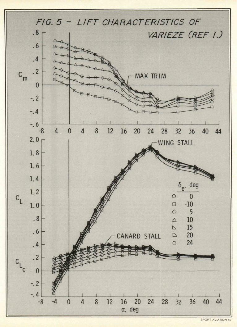
FIG. 5 - LIFT CHARACTERISTICS OF• 8 f VARIEZE (REF I.)
Q-«..6
m
- 8 - 4 0 4 8 12 16 20 24 28 32 36 40 44WING STALL
CANARD STALL
12 16 20 24a, cleg
28 32 36 40 44
SPORT AVIATION 49
CANARD TRANSITION
.4
.3
.2
.1
0
O FREED FIXEDO FREE, WATER ON
,01 .02 .03 .04 .05 .06 .07
- 4 0 4 8 12 16 20 24 28 32 36 40 44a,deg
FIG. 6 - EFFECTS OF CONTAMINATION ON CANARD.
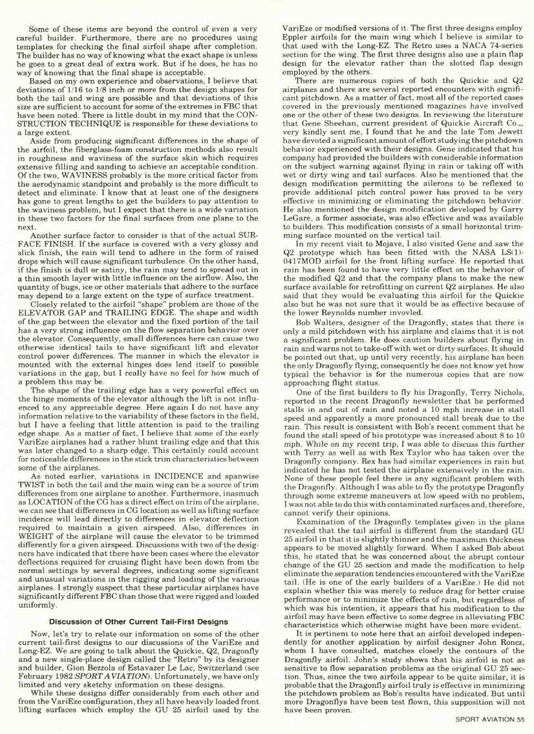
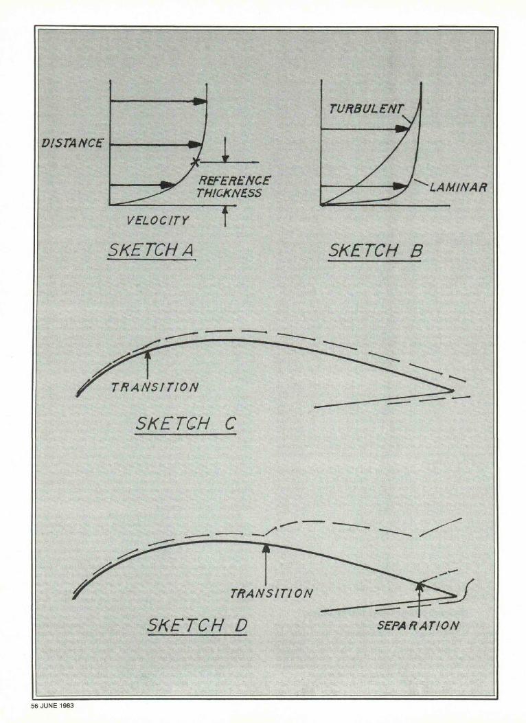
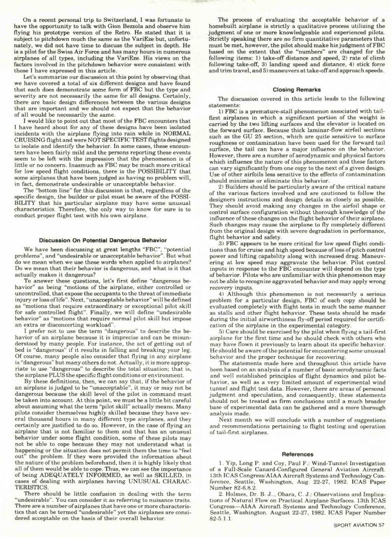
The boundary layer grows in thickness from just a fewmolecules at the nose to several tenths of an inch as the flowprogresses toward the trailing edge. If we were to measure thevelocity distribution across the boundary layer with a very smallvelocity probe and plot the variation of the velocity as a functionof the distance from the airfoil surface, we would be looking atwhat is called a "velocity profile" as shown in Sketch A. As youcan see, the actual outer edge of the layer where the velocitybecomes constant is very difficult to locate, so for convenience weactually refer to the thickness as that point where the velocityhas reached some arbitrary percentage of the free stream velocityabove the surface. We are not really interested in the actualthickness for this discussion but rather in the manner in whichit changes and the character of the flow within this layer.
The flow in the boundary layer near the nose of the airfoil isvery orderly as the molecules slide smoothly, one over the other,and we have what is called "laminar" flow as long as the surfaceitself is relatively smooth. This results in a low drag or shearingforce on the airfoil. The velocity profile for laminar flow shows avery rapid increase in velocity in a distance of only a fewmolecules. The shape of the profile is depicted in Sketch B. Al-though the boundary layer gets progressively thicker as the flowmoves aft from the nose, the shape of the profile does not change.The significance of this is that the molecules within the boundarylayer maintain most of their energy and are able to continuemoving in a uniform manner following the contour of the airfoilfor some distance. The greater the distance the laminar flowcontinues, the lower the drag will be.
At some point along the airfoil, however, the molecules aregoing to start loosing their uniform motion and begin to tumbleover each other. This action is referred to as "transition" and the50 JUNE 1983
point where this occurs is referred to as the "transition point". Atthis point, the layer thickens, as illustrated in Sketch C, and theflow from here on to the trailing edge and beyond is very randomin nature and referred to as "turbulent". The velocity profile forthis condition, also shown in Sketch B, indicates that not onlyhas thickness increased but the velocity of the molecules at agiven distance has decreased greatly. This condition creates muchmore drag on the airfoil and the flow finds it much more difficultto follow the contour of the airfoil exactly. Although the lift beinggenerated by the airfoil is not altered to any significant degreeby the transition to turbulent flow, the POTENTIAL FOR SEP-ARATION of the flow from the airfoil altogether is increased. Ifseparation does occur, the result is then a marked loss of lift overthose portions of the airfoil aft of the "separation point". In effect,the flow at the separation point starts to reverse direction andthe air from the lower surface starts to spill over the trailing edge.
Two of the key factors affecting the SEPARATION POINT arethe THICKNESS of the boundary layer and the LOCATION OFTHE TRANSITION POINT. If the transition point is locatedFORWARD on the airfoil where the boundary layer is quite thin,then the boundary layer becomes thicker immediately behind thetransition point, as indicated in Sketch C, but the overall velocityor energy level within the turbulent boundary layer is relativelyhigh. The potential for separation in this case is RELATIVELYLOW. If, on the other hand, the transition point is located muchfurther AFT where the laminar boundary layer has thickenedconsiderably and become "aged", that is, the molecules close tothe surface have lost most of their energy, then the turbulentlayer that now forms is very much thicker, as indicated in SketchD, and its energy level is greatly reduced. The potential forseparation is now RELATIVELY HIGH.
The expanding shape of the forward portions of all airfoilscreates a positive pressure gradient which helps the air moleculesmove out of the way of the wing as it passes through the air. Thisfavorable gradient also helps to damp or stabilize the smallamounts of airflow turbulence that tend to build up in the boun-dary layer. This causes the TRANSITION POINT to be furtheraft on the airfoil than it would be if there were no favorablegradient.
The tapering shape of the rear portion of the airfoil creates anegative or adverse pressure gradient which tends to cause theairflow to become turbulent sooner than it would if there wereno adverse gradient. Thus the TRANSITION POINT tends tomove forward in the presence of such a gradient. Not only thisbut also the negative gradient, if strong enough, will cause theSEPARATION TO OCCUR PREMATURELY.
Increasing angle of attack to produce greater lift increases thepressure gradients over both portions of the airfoil. This increasein the negative gradients over the aft portion is what causes theairfoil to stall ultimately. If one airfoil at zero lift has a greaternegative gradient than another airfoil due to greater trailing-edgetaper, then that airfoil will stall at a lower angle of attack anddevelop less lift than the other.
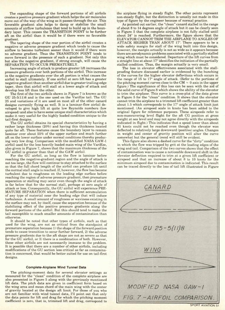
The first of the two airfoils shown in Figure 7 is known as theGU 25-5(11)8 and is the one used on the VariEze tail. The GU25 and variations of it are used on most all of the other canarddesigns currently flying as well. It is a laminar-flow airfoil de-veloped to give high lift at quite low Reynolds numbers (lowairspeed) and also to have some unique stall characteristics whichmake it very useful for the highly loaded condition unique to thetail-first designs.
The GU airfoil obtains its special characteristics by having arather large thickness (20%) and having this thickness locatedquite far aft. These features cause the boundary layer to remainlaminar over about 55% of the upper surface and much furtheraft on the lower surface under normal conditions thereby produc-ing very low drag. Comparison with the modified NASA GAW-1airfoil used for the less heavily loaded main wing of the VariEze,also given in Figure 7, shows that the maximum thickness of theGU airfoil is greater than that of the GAW airfoil.
For the GU airfoil, as long as the flow is laminar beforereaching the negative-gradient region and the angle of attack isnot too large, the flow will continue to stay attached to the surfaceso that the full chord length of the airfoil can produce lift untilthe normal stall angle is reached. If, however, the flow has becometurbulent due to roughness on the leading edge surface beforereaching the region of adverse pressure gradient, then prematureseparation or stalling may occur even though the angle of attackis far below that for the normal stall, perhaps at zero angle ofattack or less. Consequently, the GU airfoil will experience PRE-MATURE SEPARATION when there is sufficient accumulationof any type of material near the leading edge that will induceturbulence. A small amount of roughness or waviness existing inthe surface may not, by itself, cause the separation because of thestabilizing effect of the positive pressure gradients along theforward portions of the airfoil. But this should tend to make thetail susceptible to much smaller amounts of contamination thanotherwise.
It should be noted that other types of airfoils, such as thatused for the wing, are not as critical from the standpoint ofpremature separation because 1) the shape of the forward positiontends to cause transition to occur further forward, 2) the adversepressure gradients due to the aft shape are not as severe as thatfor the GU airfoil, or 3) there is a combination of both. However,these other airfoils are not necessarily immune to the problem.It is possible that there are a number of other airfoils, includingmodifications of the GU section less critical as far as contamina-tion is concerned, that would be better suited for use on tail-firstdesigns.
Complete-Airplane Wind Tunnel DataThe pitching-moment data for several elevator settings as
measured for the "clean" condition of the complete airplane arealso presented in Figure 5 along with the previously mentionedlift data. The pitch data are given in coefficient form based onthe wing area and mean chord of the main wing with the centerof gravity located at the design aft limit. For those of you whoare not familiar with wind tunnel data, I'll point out that onlythe data points for lift and drag for which the pitching momentcoefficient is zero, that is, trimmed lift and drag, correspond to
the airplane flying in steady flight. The other points representnon-steady flight, but the distinction is usually not made in thistype of figure by the engineer because of normal practice.
As pointed out earlier, the "clean" canard stalled in the rangeof about 8 to 14 degrees angle of attack but it can be clearly seenin Figure 5 that the complete airplane is not fully stalled untilabout 24° is reached. Furthermore, the figure shows that theELEVATOR CANNOT TRIM THE AIRPLANE TO ANGLES OFATTACK HIGHER THAN ABOUT 17°. There appears to be awide safety margin for stall of the wing built into this design,however, the margin actually is not as wide as it appears becausethere are aerodynamic problems associated with a partially stalledwing which must be considered. Departure of the lift curves froma straight line at about 17° identifies the initiation of the partiallystalled condition. Thus, the margin actually is very small.
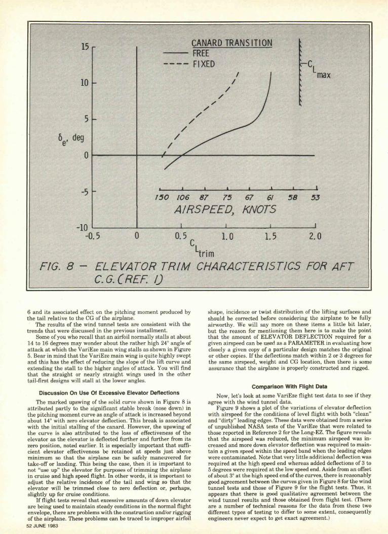
The loss in elevator effectiveness associated with the stall-proofing feature discussed earlier is evidenced by the bunchingof the curves for the higher elevator deflections which occurs inthe range of 15 to 17° angle of attack. (Refer to the portions ofthe pitching moment curves close to the CM = 0 axis in the upperfigure.) The significance of this loss can be seen with the aid ofthe solid curve of Figure 8 which shows the ability of the elevatorto trim the airplane. This curve is a cross-plot of the data givenin Figure 5 for the "clean" condition. It shows that the elevatorcannot trim the airplane to a trimmed lift coefficient greater thanabout 1.5 which corresponds to the 17° angle of attack limit justmentioned. (An airspeed scale in knots has been added to theoriginal figure for reference purposes. These airspeeds refer tonon-maneuvering level flight for the aft CG position at grossweight at sea level and may not agree directly with the airspeedsindicated in flight.) This indicates that a speed lower than about61 knots could not be reached even though the elevator wasdeflected to relatively large downward (positive) angles. Changesin weight and center of gravity position will alter the curvesomewhat but the general trend will still be evident.
This figure also shows a dashed curve for the "dirty" conditionin which the flow was tripped by grit at the leading edges of thewing and tail. Comparison of the two curves shows that the effectof contamination was to cause a noticeable downward shift in theelevator deflection required to trim at a given lift coefficient orairspeed and that an increase of about 8 to 10 knots for theminimum airspeed due to contamination is indicated. This resultcan be traced directly to the loss of tail lift illustrated in Figure
CANARD
GU 25-5(11)8
WING
MODIFIED NASA GAW-I
FIG. 7-AIRFOIL COMPARISON.SPORT AVIATION 51
15
10
0
-5
-10
CANARD TRANSITIONFREE
——— FIXEDmax
150 106 87 75 67 61 58 53AIRSPEED, KNOTS
-0.5 0 0.5 1.0 1.5 2.0Ltrim
FIG. 8 - ELEVATOR TRIM CHARACTERISTICS FOR AFTC.G.CREF. 0
6 and its associated effect on the pitching moment produced bythe tail relative to the CG of the airplane.
The results of the wind tunnel tests are consistent with thetrends that were discussed in the previous installment.
Some of you who recall that an airfoil normally stalls at about14 to 16 degrees may wonder about the rather high 24° angle ofattack at which the VariEze main wing stalls as shown in Figure5. Bear in mind that the VariEze main wing is quite highly sweptand this has the effect of reducing the slope of the lift curve andextending the stall to the higher angles of attack. You will findthat the straight or nearly straight wings used in the othertail-first designs will stall at the lower angles.
Discussion On Use Of Excessive Elevator DeflectionsThe marked upswing of the solid curve shown in Figure 8 is
attributed partly to the significant stable break (nose down) inthe pitching moment curve as angle of attack is increased beyondabout 14° with zero elevator deflection. This break is associatedwith the initial stalling of the canard. However, the upswing ofthe curve is also attributed to the loss of effectiveness of theelevator as the elevator is deflected further and further from itszero position, noted earlier. It is especially important that suffi-cient elevator effectiveness be retained at speeds just aboveminimum so that the airplane can be safely maneuvered fortake-off or landing. This being the case, then it is important tonot "use up" the elevator for purposes of trimming the airplanein cruise and high speed flight. In other words, it is important toadjust the relative incidence of the tail and wing so that theelevator will be trimmed close to zero deflection or, perhaps,slightly up for cruise conditions.
If flight tests reveal that excessive amounts of down elevatorare being used to maintain steady conditions in the normal flightenvelope, there are problems with the construction and/or riggingof the airplane. These problems can be traced to improper airfoil52 JUNE 1983
shape, incidence or twist distribution of the lifting surfaces andshould be corrected before considering the airplane to be fullyairworthy. We will say more on these items a little bit later,but the reason for mentioning them here is to make the pointthat the amount of ELEVATOR DEFLECTION required for agiven airspeed can be used as a PARAMETER in evaluating howclosely a given copy of a particular design matches the originalor other copies. If the deflections match within 2 or 3 degrees forthe same airspeed, weight and CG location, then there is someassurance that the airplane is properly constructed and rigged.
Comparison With Flight DataNow, let's look at some VariEze flight test data to see if they
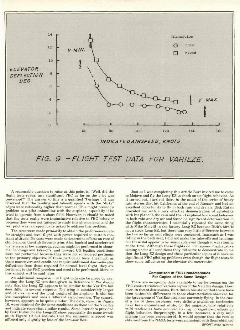
agree with the wind tunnel data.Figure 9 shows a plot of the variations of elevator deflection
with airspeed for the conditions of level flight with both "clean"and "dirty" leading edges. These data were obtained from a seriesof unpublished NASA tests of the VariEze that were related tothose reported in Reference 2 for the Long-EZ. The figure revealsthat the airspeed was reduced, the minimum airspeed was in-creased and more down elevator deflection was required to main-tain a given speed within the speed band when the leading edgeswere contaminated. Note that very little additional deflection wasrequired at the high speed end whereas added deflections of 3 to5 degrees were required at the low speed end. Aside from an offsetof about 3° at the high speed end of the curves, there is reasonablygood agreement between the curves given in Figure 8 for the windtunnel tests and those of Figure 9 for the flight tests. Thus, itappears that there is good qualitative agreement between thewind tunnel results and those obtained from flight test. (Thereare a number of technical reasons for the data from these twodifferent types of testing to differ to some extent, consequentlyengineers never expect to get exact agreement.)
14
12
10
ELEVATORDEFLECTION 8
DE6.6
V MIN.
Transition
free
fixed
o
V MAX.
I_
60 80 100 120 140
INDICATEDAIRSPEED, KNOTS
160
FIG. 9 -FLIGHT TEST DATA FOR VARIEZE.
A reasonable question to raise at this point is, "Well, did theflight tests reveal any significant FBC as far as the pilot wasconcerned?" The answer to this is a qualified "Perhaps". It wasobserved that the landing and take-off speeds with the "dirty"edges were noticeably higher than normal. This might present aproblem to a pilot unfamiliar with the airplane, especially if hetried to operate from a short field. However, it should be notedthat the tests really were inconclusive relative to FBC behaviorbecause they were not tailored to study this phenomenon and thetest pilot was not specifically asked to address this problem.
The tests were made primarily to obtain the performance datafor straight and level flight with power required to sustain con-stant altitude. No tests were made to determine effects on rate ofclimb and on the stick forces or trim. Also, banked and acceleratedmaneuvers at low airspeeds, such as might be performed in abnor-mal landings and take-offs, and forward CG loading conditionswere not performed because they were not considered pertinentto the primary objective of these particular tests. Inasmuch asthese maneuvers and conditions require additional down-elevatordeflections from those required for normal level flight, they arepertinent to the FBC problem and need to be performed. More onthis subject will be said later.
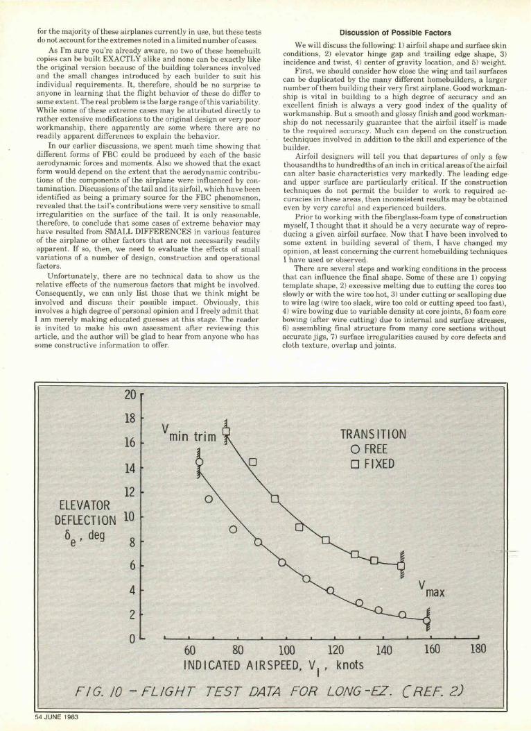
An additional comparison of flight data can be made by exa-mining the Long-EZ test data given in Reference 2. We shouldnote that the Long-EZ appears to be similar to the VariEze butdoes differ in several respects. The wing is considerably largerand carries more of the total weight of the airplane. It also hasless sweepback and uses a different airfoil section. The canard,however, appears to be quite similar. The data, shown in Figure10, were obtained for the same conditions as those for the VariEzeand indicate somewhat similar results. Some later data providedby Burt Rutan for the Long-EZ show essentially the same trendsas in Figure 10 but indicate that the minimum airspeed wasaffected only slightly by loss of the laminar flow.
Just as I was completing this article Burt invited me to cometo Mojave and fly the Long-EZ to check on its flight behavior. Asit turned out, I arrived there in the midst of the series of heavyrain storms that hit California at the end of January and had anexcellent opportunity to fly in both rain and dry air. Dick Rutanprovided me with a very effective demonstration of aerobaticswith his plane in the rain and then I explored low speed behaviorin both rain and dry air and found no significant deterioration inthe flight characteristics. I essentially repeated the same thingwith Mike Melvill in the factory Long-EZ because Dick's bird isnot a stock Long-EZ, but there was very little difference betweenthe two as far as rain effects were concerned. Inasmuch as I wasriding in the back seat, I did not make the take-offs and landingsbut these did appear to be reasonable even though it was rainingat the time. Although these flights do not represent exhaustivetesting under all conditions they did serve to demonstrate to methat the Long-EZ design and these particular copies of it have nosignificant FBC piloting problems even though the flight tests doshow some influence on the elevator characteristics.
Comparison of FBC CharacteristicsFor Copies of the Same Design
There are no specific data available to me for comparing theFBC characteristics of various copies of the VariEze design. How-ever, in recent discussions, Burt Rutan has stated that there havebeen noticeable differences in these characteristics observed forthe large group of VariEze airplanes currently flying. In the caseof a few of these airplanes, very definite pitchdown tendencieshave been encountered while, for the majority, only relativelymild tendencies have occurred having no significant effects onflight behavior. Surprisingly, in a few instances, a very mildpitchup has been encountered. It would appear that the resultsobtained from the NASA tests were consistent with those obtained
SPORT AVIATION 53
for the majority of these airplanes currently in use, but these testsdo not account for the extremes noted in a limited number of cases.
As I'm sure you're already aware, no two of these homebuiltcopies can be built EXACTLY alike and none can be exactly likethe original version because of the building tolerances involvedand the small changes introduced by each builder to suit hisindividual requirements. It, therefore, should be no surprise toanyone in learning that the flight behavior of these do differ tosome extent. The real problem is the large range of this variability.While some of these extreme cases may be attributed directly torather extensive modifications to the original design or very poorworkmanship, there apparently are some where there are noreadily apparent differences to explain the behavior.
In our earlier discussions, we spent much time showing thatdifferent forms of FBC could be produced by each of the basicaerodynamic forces and moments. Also we showed that the exactform would depend on the extent that the aerodynamic contribu-tions of the components of the airplane were influenced by con-tamination. Discussions of the tail and its airfoil, which have beenidentified as being a primary source for the FBC phenomenon,revealed that the tail's contributions were very sensitive to smallirregularities on the surface of the tail. It is only reasonable,therefore, to conclude that some cases of extreme behavior mayhave resulted from SMALL DIFFERENCES in various featuresof the airplane or other factors that are not necessarily readilyapparent. If so, then, we need to evaluate the effects of smallvariations of a number of design, construction and operationalfactors.
Unfortunately, there are no technical data to show us therelative effects of the numerous factors that might be involved.Consequently, we can only list those that we think might beinvolved and discuss their possible impact. Obviously, thisinvolves a high degree of personal opinion and I freely admit thatI am merely making educated guesses at this stage. The readeris invited to make his own assessment after reviewing thisarticle, and the author will be glad to hear from anyone who hassome constructive information to offer.
Discussion of Possible FactorsWe will discuss the following: 1) airfoil shape and surface skin
conditions, 2) elevator hinge gap and trailing edge shape, 3)incidence and twist, 4) center of gravity location, and 5) weight.
First, we should consider how close the wing and tail surfacescan be duplicated by the many different homebuilders, a largernumber of them building their very first airplane. Good workman-ship is vital in building to a high degree of accuracy and anexcellent finish is always a very good index of the quality ofworkmanship. But a smooth and glossy finish and good workman-ship do not necessarily guarantee that the airfoil itself is madeto the required accuracy. Much can depend on the constructiontechniques involved in addition to the skill and experience of thebuilder.
Airfoil designers will tell you that departures of only a fewthousandths to hundredths of an inch in critical areas of the airfoilcan alter basic characteristics very markedly. The leading edgeand upper surface are particularly critical. If the constructiontechniques do not permit the builder to work to required ac-curacies in these areas, then inconsistent results may be obtainedeven by very careful and experienced builders.
Prior to working with the fiberglass-foam type of constructionmyself, I thought that it should be a very accurate way of repro-ducing a given airfoil surface. Now that I have been involved tosome extent in building several of them, I have changed myopinion, at least concerning the current homebuilding techniquesI have used or observed.
There are several steps and working conditions in the processthat can influence the final shape. Some of these are 1) copyingtemplate shape, 2) excessive melting due to cutting the cores tooslowly or with the wire too hot, 3) under cutting or scalloping dueto wire lag (wire too slack, wire too cold or cutting speed too fast),4) wire bowing due to variable density at core joints, 5) foam corebowing (after wire cutting) due to internal and surface stresses,6) assembling final structure from many core sections withoutaccurate jigs, 7) surface irregularities caused by core defects andcloth texture, overlap and joints.
2018
16
14
12ELEVATOR
DEFLECTION 10
6e ' de9 8
6
4
2
0
Vmin trim ITIONTRANSOFRD FIXED
Vmax
60 80 100 120 140 160 180INDICATED AIRSPEED, V( , knots
FIG. 10 -FLIGHT TEST DATA FOR LONG-EZ. CFtEF. 2)
54 JUNE 1983
Some of these items are beyond the control of even a verycareful builder. Furthermore, there are no procedures usingtemplates for checking the final airfoil shape after completion.The builder has no way of knowing what the exact shape is unlesshe goes to a great deal of extra work. But if he does, he has noway of knowing that the final shape is acceptable.
Based on my own experience and observations, I believe thatdeviations of 1/16 to 1/8 inch or more from the design shapes forboth the tail and wing are possible and that deviations of thissize are sufficient to account for some of the extremes in FBC thathave been noted. There is little doubt in my mind that the CON-STRUCTION TECHNIQUE is responsible for these deviations toa large extent.
Aside from producing significant differences in the shape ofthe airfoil, the fiberglass-foam construction methods also resultin roughness and waviness of the surface skin which requiresextensive filling and sanding to achieve an acceptable condition.Of the two, WAVINESS probably is the more critical factor fromthe aerodynamic standpoint and probably is the more difficult todetect and eliminate. I know that at least one of the designershas gone to great lengths to get the builders to pay attention tothe waviness problem, but I expect that there is a wide variationin these two factors for the final surfaces from one plane to thenext.
Another surface factor to consider is that of the actual SUR-FACE FINISH. If the surface is covered with a very glossy andslick finish, the rain will tend to adhere in the form of raiseddrops which will cause significant turbulence. On the other hand,if the finish is dull or satiny, the rain may tend to spread out ina thin smooth layer with little influence on the airflow. Also, thequantity of bugs, ice or other materials that adhere to the surfacemay depend to a large extent on the type of surface treatment.
Closely related to the airfoil "shape" problem are those of theELEVATOR GAP and TRAILING EDGE. The shape and widthof the gap between the elevator and the fixed portion of the tailhas a very strong influence on the flow separation behavior overthe elevator. Consequently, small differences here can cause twootherwise identical tails to have significant lift and elevatorcontrol power differences. The manner in which the elevator ismounted with the external hinges does lend itself to possiblevariations in the gap, but I really have no feel for how much ofa problem this may be.
The shape of the trailing edge has a very powerful effect onthe hinge moments of the elevator although the lift is not influ-enced to any appreciable degree. Here again I do not have anyinformation relative to the variability of these factors in the field,but I have a feeling that little attention is paid to the trailingedge shape. As a matter of fact, I believe that some of the earlyVariEze airplanes had a rather blunt trailing edge and that thiswas later changed to a sharp edge. This certainly could accountfor noticeable differences in the stick trim characteristics betweensome of the airplanes.
As noted earlier, variations in INCIDENCE and spanwiseTWIST in both the tail and the main wing can be a source of trimdifferences from one airplane to another. Furthermore, inasmuchas LOCATION of the CG has a direct effect on trim of the airplane,we can see that differences in CG location as well as lifting surfaceincidence will lead directly to differences in elevator deflectionrequired to maintain a given airspeed. Also, differences inWEIGHT of the airplane will cause the elevator to be trimmeddifferently for a given airspeed. Discussions with two of the desig-ners have indicated that there have been cases where the elevatordeflections required for cruising flight have been down from thenormal settings by several degrees, indicating some significantand unusual variations in the rigging and loading of the variousairplanes. I strongly suspect that these particular airplanes havesignificantly different FBC than those that were rigged and loadeduniformly.
Discussion of Other Current Tail-First DesignsNow, let's try to relate our information on some of the other
current tail-first designs to our discussions of the VariEze andLong-EZ. We are going to talk about the Quickie, Q2, Dragonflyand a new single-place design called the "Retro" by its designerand builder, Gion Bezzola of Estavazer Le Lac, Switzerland (seeFebruary 1982 SPORT AVIATION). Unfortunately, we have onlylimited and very sketchy information on these designs.
While these designs differ considerably from each other andfrom the VariEze configuration, they all have heavily loaded frontlifting surfaces which employ the GU 25 airfoil used by the
VariEze or modified versions of it. The first three designs employEppler airfoils for the main wing which I believe is similar tothat used with the Long-EZ. The Retro uses a NACA 74-seriessection for the wing. The first three designs also use a plain flapdesign for the elevator rather than the slotted flap designemployed by the others.
There are numerous copies of both the Quickie and Q2airplanes and there are several reported encounters with signifi-cant pitchdown. As a matter of fact, most all of the reported casescovered in the previously mentioned magazines have involvedone or the other of these two designs. In reviewing the literaturethat Gene Sheehan, current president of Quickie Aircraft Co.,,very kindly sent me, I found that he and the late Tom Jewetthave devoted a significant amount of effort studying the pitchdownbehavior experienced with their designs. Gene indicated that hiscompany had provided the builders with considerable informationon the subject warning against flying in rain or taking off withwet or dirty wing and tail surfaces. Also he mentioned that thedesign modification permitting the ailerons to be reflexed toprovide additional pitch control power has proved to be veryeffective in minimizing or eliminating the pitchdown behavior.He also mentioned the design modification developed by CarryLeGare, a former associate, was also effective and was availableto builders. This modification consists of a small horizontal trim-ming surface mounted on the vertical tail.
In my recent visit to Mojave, I also visited Gene and saw theQ2 prototype which has been fitted with the NASA LS(1>-0417MOD airfoil for the front lifting surface. He reported thatrain has been found to have very little effect on the behavior ofthe modified Q2 and that the company plans to make the newsurface available for retrofitting on current Q2 airplanes. He alsosaid that they would be evaluating this airfoil for the Quickiealso but he was not sure that it would be as effective because ofthe lower Reynolds number invovled.
Bob Walters, designer of the Dragonfly, states that there isonly a mild pitchdown with his airplane and claims that it is nota significant problem. He does caution builders about flying inrain and warns not to take-off with wet or dirty surfaces. It shouldbe pointed out that, up until very recently, his airplane has beenthe only Dragonfly flying, consequently he does not know yet howtypical the behavior is for the numerous copies that are nowapproaching flight status.
One of the first builders to fly his Dragonfly, Terry Nichols,reported in the recent Dragonfly newsletter that he performedstalls in and out of rain and noted a 10 mph increase in stallspeed and apparently a more pronounced stall break due to therain. This result is consistent with Bob's recent comment that hefound the stall speed of his prototype was increased about 8 to 10mph. While on my recent trip, I was able to discuss this furtherwith Terry as well as with Rex Taylor who has taken over theDragonfly company. Rex has had similar experiences in rain butindicated he has not tested the airplane extensively in the rain.None of these people feel there is any significant problem withthe Dragonfly. Although I was able to fly the prototype Dragonflythrough some extreme maneuvers at low speed with no problem,I was not able to do this with contaminated surfaces and, therefore,cannot verify their opinions.
Examination of the Dragonfly templates given in the plansrevealed that the tail airfoil is different from the standard GU25 airfoil in that it is slightly thinner and the maximum thicknessappears to be moved slightly forward. When I asked Bob aboutthis, he stated that he was concerned about the abrupt contourchange of the GU 25 section and made the modification to helpeliminate the separation tendencies encountered with the VariEzetail. (He is one of the early builders of a VariEze.) He did notexplain whether this was merely to reduce drag for better cruiseperformance or to minimize the effects of rain, but regardless ofwhich was his intention, it appears that his modification to theairfoil may have been effective to some degree in alleviating FBCcharacteristics which otherwise might have been more evident.
It is pertinent to note here that an airfoil developed indepen-dently for another application by airfoil designer John Roncz,whom I have consulted, matches closely the contours of theDragonfly airfoil. John's study shows that his airfoil is not assensitive to flow separation problems as the original GU 25 sec-tion. Thus, since the two airfoils appear to be quite similar, it isprobable that the Dragonfly airfoil truly is effective in minimizingthe pitchdown problem as Bob's results have indicated. But untilmore Dragonflys have been test flown, this supposition will nothave been proven.
SPORT AVIATION 55
DISTANCE
REFERENCETHICKNESS
VELOCITY f
SKETCH A
SKETCH C
LAMINAR
SKETCH B
TRANSITION
SKETCH D SEPARATION
56 JUNE 1983
On a recent personal trip to Switzerland, I was fortunate tohave the opportunity to talk with Gion Bezzola and observe himflying his prototype version of the Retro. He stated that it issubject to pitchdown much the same as the VariEze but, unfortu-nately, we did not have time to discuss the subject in depth. Heis a pilot for the Swiss Air Force and has many hours in numerousairplanes of all types, including the VariEze. His views on thefactors involved in the pitchdown behavior were consistent withthose I have expressed in this article.
Let's summarize our discussion at this point by observing thatwe have covered a total of six different designs and have foundthat each does demonstrate some form of FBC but the type andseverity are not necessarily the same for all designs. Certainly,there are basic design differences between the various designsthat are important and we should not expect that the behaviorof all would be necessarily the same.
I would like to point out that most of the FBC encounters thatI have heard about for any of these designs have been isolatedincidents with the airplane flying into rain while in NORMALCRUISING flight and were NOT SPECIFIC TEST flights designedto isolate and identify the behavior. In some cases, these encoun-ters have been fairly mild and the persons reporting these eventsseem to be left with the impression that the phenomenon is oflittle or no concern. Inasmuch as FBC may be much more criticalfor low speed flight conditions, there is the POSSIBILITY thatsome airplanes that have been judged as having no problem will,in fact, demonstrate undesirable or unacceptable behavior.
The "bottom line" for this discussion is that, regardless of thespecific design, the builder or pilot must be aware of the POSSI-BILITY that his particular airplane may have some unusualcharacteristics. Therefore, the only way to know for sure is toconduct proper flight test with his own airplane.
Discussion On Potential Dangerous BehaviorWe have been discussing at great lengths "FBC", "potential
problems", and "undesirable or unacceptable behavior". But whatdo we mean when we use these words when applied to airplanes?Do we mean that their behavior is dangerous, and what is it thatactually makes it dangerous?
To answer these questions, let's first define "dangerous be-havior" as being "motions of the airplane, either controlled oruncontrolled, that expose the occupants to the threat of immediateinjury or loss of life". Next, "unacceptable behavior" will be definedas "motions that require extraordinary or exceptional pilot skillfor safe controlled flight". Finally, we will define "undesirablebehavior" as "motions that require normal pilot skill but imposean extra or disconcerting workload".
I prefer not to use the term "dangerous" to describe the be-havior of an airplane because it is imprecise and can be misun-derstood by many people. For instance, the act of getting out ofbed is "dangerous" if it results in falling and breaking your leg.Of course, many people also consider that flying in any airplaneis "dangerous" but many others do not. Actually, it is more approp-riate to use "dangerous" to describe the total situation; that is,the airplane PLUS the specific flight conditions or environment.
By these definitions, then, we can say that, if the behavior ofan airplane is judged to be "unacceptable", it may or may not bedangerous because the skill level of the pilot in command mustbe taken into account. At this point, we must be a little bit carefulabout assuming what the term "pilot skill" actually means. Manypilots consider themselves highly skilled because they have sev-eral thousand hours in many different type airplanes, and theycertainly are justified to do so. However, in the case of flying anairplane that is not familiar to them and that has an unusualbehavior under some flight condition, some of these pilots maynot be able to cope because they may not understand what ishappening or the situation does not permit them the time to "feelout" the problem. If they were provided the information aboutthe nature of the problem beforehand, then it is highly likely thatall of them would be able to cope. Thus, we can see the importanceof being ADEQUATELY INFORMED, as well as SKILLED, incases of dealing with airplanes having UNUSUAL CHARAC-TERISTICS.
There should be little confusion in dealing with the term"undesirable". You can consider it as referring to nuisance traits.There are a number of airplanes that have one or more characteris-tics that can be termed "undesirable" yet the airplanes are consi-dered acceptable on the basis of their overall behavior.
The process of evaluating the acceptable behavior of ahomebuilt airplane is strictly a qualitative process utilizing thejudgment of one or more knowledgeable and experienced pilots.Strictly speaking there are no firm quantitative parameters thatmust be met, however, the pilot should make his judgment of FBCbased on the extent that the "numbers" are changed for thefollowing items: 1) take-off distance and speed, 2) rate of climbfollowing take-off, 3) landing speed and distance, 4) stick forceand trim travel, and 5) maneuvers at take-off and approach speeds..
Closing RemarksThe discussion covered in this article leads to the following
statements:1) FBC is a premature-stall phenomenon associated with tail-
first airplanes in which a significant portion of the weight iscarried by the two lifting surfaces and the elevator is located onthe forward surface. Because thick laminar-flow airfoil sectionssuch as the GU 25 section, which are quite sensitive to surfaceroughness or contamination have been used for the forward tailsurface, the tail can have a major influence on the behavior.However, there are a number of aerodynamic and physical factorswhich influence the nature of this phenomenon and these factorscan vary significantly from one copy to the next of a given design.Use of other airfoils less sensitive to the effects of contaminationshould minimize or eliminate this behavior.
2) Builders should be particularly aware of the critical natureof the various factors involved and are cautioned to follow thedesigners instructions and design details as closely as possible.They should avoid making any changes in the airfoil shape orcontrol surface configuration without thorough knowledge of theinfluence of these changes on the flight behavior of their airplane.Such changes may cause the airplane to fly completely differentfrom the original design with severe degradation in performance,flight behavior and safety.
3) FBC appears to be more critical for low speed flight condi-tions than for cruise and high speed because of loss of pitch controlpower and lifting capability along with increased drag. Maneuv-ering at low speed may aggravate the behavior. Pilot controlinputs in response to the FBC encounter will depend on the typeof behavior. Pilots who are unfamiliar with this phenomenon maynot be able to recognize aggravated behavior and may apply wrongrecovery inputs.
4) Although this phenomenon is not necessarily a seriousproblem for a particular design, FBC of each copy should beevaluated completely with flight tests in much the same manneras stalls and other flight behavior. These tests should be madeduring the initial airworthiness fly-off period required for certifi-cation of the airplane in the experimental category.
5) Care should be exercised by the pilot when flying a tail-firstairplane for the first time and he should check with others whomay have flown it previously to learn about its specific behavior.He should be aware of the potential for encountering some unusualbehavior and the proper technique for recovering.
The statements made here and throughout this article havebeen based on an analysis of a number of basic aerodynamic factsand well established principles of flight dynamics and pilot be-havior, as well as a very limited amount of experimental windtunnel and flight test data. However, there are areas of personaljudgment and speculation, and consequently, these statementsshould not be treated as firm conclusions until a much broaderbase of experimental data can be gathered and a more thoroughanalysis made.
Next month we will conclude with a number of suggestionsand recommendations pertaining to flight testing and operationof tail-first airplanes.
References1. Yip, Long P. and Coy, Paul F.: Wind-Tunnel Investigation
of a Full-Scale Canard-Configured General Aviation Aircraft.13th ICAS Congress; AIAA Aircraft Systems and Technology Con-ference, Seattle, Washington, Aug. 22-27, 1982. ICAS PaperNumber 82-6.8.2.
2. Holmes, Dr. B. J.., Obara, C. J.: Observations and Implica-tions of Natural Flow on Practical Airplane Surfaces. 13th ICASCongress—AIAA Aircraft Systems and Technology Conference,Seattle, Washington. August 22-27, 1982. ICAS Paper Number82-5.1.1.
SPORT AVIATION 57