the star forward g em t racker (fgt ) - bnl.gov fileoutline 2 fgt fgt physics motivation - w program...
TRANSCRIPT
Bernd Surrow
AGS-RHIC Users Meeting, Workshop Session 3 - Upgrades Upton, NY, May 27, 2008 Bernd Surrow
1
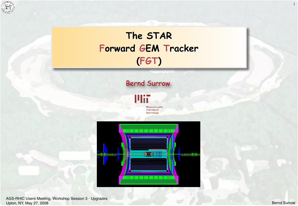
The STARForward GEM Tracker
(FGT)

Bernd SurrowAGS-RHIC Users Meeting, Workshop Session 3 - Upgrades Upton, NY, May 27, 2008
Outline2
FGT
FGT Physics motivation - W program
FGT Layout - Simulation results and optimization
FGT Technical Realization
Triple-GEM detector development - R&D
Mechanical design
Front-End Electronics
DAQ
FGT Schedule / Milestones
Summary
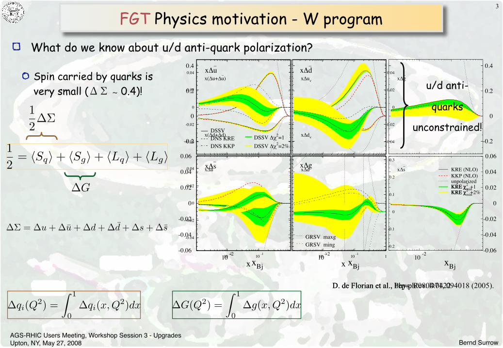
D. de Florian et al., Phys. Rev. D71, 094018 (2005).
8
parabola and the 1! uncertainty in any observable would correspond to !"2 = 1. In order to account for unexpectedsources of uncertainty, in modern unpolarized global analysis it is customary to consider instead of !"2 = 1 betweena 2% and a 5% variation in "2 as conservative estimates of the range of uncertainty.
As expected in the ideal framework, the dependence of "2 on the first moments of u and d resemble a parabola(Figures 3a and 3b). The KKP curves are shifted upward almost six units relative to those from KRE, due to thedi"erence in "2 of their respective best fits. Although this means that the overall goodness of KKP fit is poorer thanKRE, #d and #u seem to be more tightly constrained. The estimates for #d computed with the respective best fitsare close and within the !"2 = 1 range, suggesting something close to the ideal situation. However for #u, they onlyoverlap allowing a variation in !"2 of the order of a 2%. This is a very good example of how the !"2 = 1 does notseem to apply due to an unaccounted source of uncertainty: the di"erences between the available sets of fragmentationfunctions.
-0.2
0
0.2
0.4
-0.2
0
0.2
0.4
-0.06
-0.04
-0.02
0
0.02
0.04
0.06
10-2
10-2
x(!u+!u–)
x(!d+!d–)
x!uv
x!dv
x!g–
x!u–
xBj
x!d–
xBj
x!s–
xBj
KRE (NLO)
KKP (NLO)unpolarizedKRE "
2KRE "
min+1
KRE "2
KRE "min
+2%
-0.06
-0.04
-0.02
0
0.02
0.04
0.06
10-2
FIG. 4: Parton densities at Q2 = 10 GeV2, and the uncertainty bands corresponding to !!2 = 1 and !!2 = 2%
An interesting thing to notice is that almost all the variation in "2 comes from the comparison to pSIDIS data.The partial "2 value computed only with inclusive data, "2
pDIS , is almost flat reflecting the fact the pDIS data are
not sensitive to u and d distributions. In Figure 3, we plot "2pDIS with an o"set of 206 units as a dashed-dotted line.
The situation however changes dramatically when considering #s or #g as shown in Figures 3c and 3f, respectively.In the case of the variation with respect to #s, the profile of "2 is not at all quadratic, and the distribution is muchmore tightly constrained (notice that the scale used for #s is almost four times smaller than the one used for lightsea quarks moments). The "2
pDIS corresponding to inclusive data is more or less indi"erent within an interval aroundthe best fit value and increases rapidly on the boundaries. This steep increase is related to a positivity constraints on!s and !g. pSIDIS data have a similar e"ect but also helps to define a minimum within the interval. The preferredvalues for #s obtained from both NLO fits are very close, and in the case of KRE fits, it is also very close to thoseobtained for #u and #d suggesting SU(3) symmetry.
Bernd SurrowAGS-RHIC Users Meeting, Workshop Session 3 - Upgrades Upton, NY, May 27, 2008
FGT Physics motivation - W program3
12
= !Sq" + !Sg" + !Lq" + !Lg"
!" = !u + !u + !d + !d + !s + !s
!G
What do we know about u/d anti-quark polarization?
Spin carried by quarks is very small (ΔΣ ∼ 0.4)!
!qi(Q2) =! 1
0!qi(x,Q2)dx !G(Q2) =
! 1
0!g(x,Q2)dx
12!"
-0.04
-0.02
0
0.02
0.04
-0.04
-0.02
0
0.02
0.04
-0.04
-0.02
0
0.02
0.04
10 -2 10 -1
DSSVDNS KREDNS KKP
DSSV !"2=1DSSV !"2=2%
x!u–
x!d–
x!s–
x
GRSV maxgGRSV ming
x!g
x
-0.2
-0.1
0
0.1
0.2
0.3
10 -2 10 -1 1
D. de Florian et al., hep-ph/0804.0422
u/d anti-
quarks
unconstrained!
AWL =
1P
N+(W )!N!(W )N+(W )!N!(W )
RHICBOS W simulation at 500GeV CME
00.10.20.30.40.50.60.70.80.9
1
0 20 40pT (GeV)
d!/d
p T (pb
/GeV
)
W+ for CTEQ5M
Total cross-section: 14.41<ye<2
00.10.20.30.40.50.60.70.80.9
1
0 20 40pT (GeV)
d!/d
p T (pb
/GeV
)
W- for CTEQ5M
Total cross-section: 8.01<ye<2’
0123456789
10
0 20 40pT (GeV)
d!/d
p T (pb
/GeV
)
W+ for CTEQ5M
Total cross-section: 134.7No cuts
0123456789
10
0 20 40pT (GeV)
d!/d
p T (pb
/GeV
)
W- for CTEQ5M
Total cross-section: 42.0No cuts
W! ! e! + !e
W+ ! e+ + !e
Bernd SurrowAGS-RHIC Users Meeting, Workshop Session 3 - Upgrades Upton, NY, May 27, 2008
FGT Physics motivation - W program
Quark / Anti-Quark Polarization - W production
4
!d + u!W+
!u + d!W+
!d + u!W!
!u + d!W!
!d + u!W+
!u + d!W+
W!
Key signature: High pT lepton (e-/e+ or
μ-/μ+) (Max. MW/2) - Selection of
W-/W+ : Charge sign discrimination of
high pT lepton
Required: Lepton/Hadron
discrimination
W+ pT > 20GeV/c
y lepton y lepton
W! pT > 20GeV/c
AL
AL
Bernd SurrowAGS-RHIC Users Meeting, Workshop Session 3 - Upgrades Upton, NY, May 27, 2008
FGT Physics motivation - W program
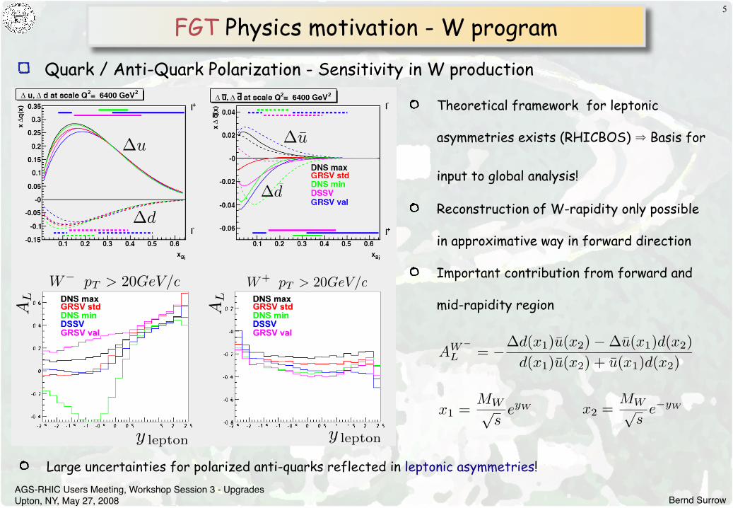
Quark / Anti-Quark Polarization - Sensitivity in W production
5
Large uncertainties for polarized anti-quarks reflected in leptonic asymmetries!
!u !u
!d
!d
x1 =MW!
seyW x2 =
MW!s
e!yW
Theoretical framework for leptonic
asymmetries exists (RHICBOS) ⇒ Basis for
input to global analysis!
Reconstruction of W-rapidity only possible
in approximative way in forward direction
Important contribution from forward and
mid-rapidity region
AW!
L = !!d(x1)u(x2)!!u(x1)d(x2)d(x1)u(x2) + u(x1)d(x2)
Bernd SurrowAGS-RHIC Users Meeting, Workshop Session 3 - Upgrades Upton, NY, May 27, 2008
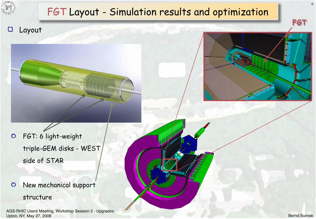
FGT Layout - Simulation results and optimization
Layout
6
FGT: 6 light-weight
triple-GEM disks - WEST
side of STAR
New mechanical support
structure
FGT
Bernd SurrowAGS-RHIC Users Meeting, Workshop Session 3 - Upgrades Upton, NY, May 27, 2008
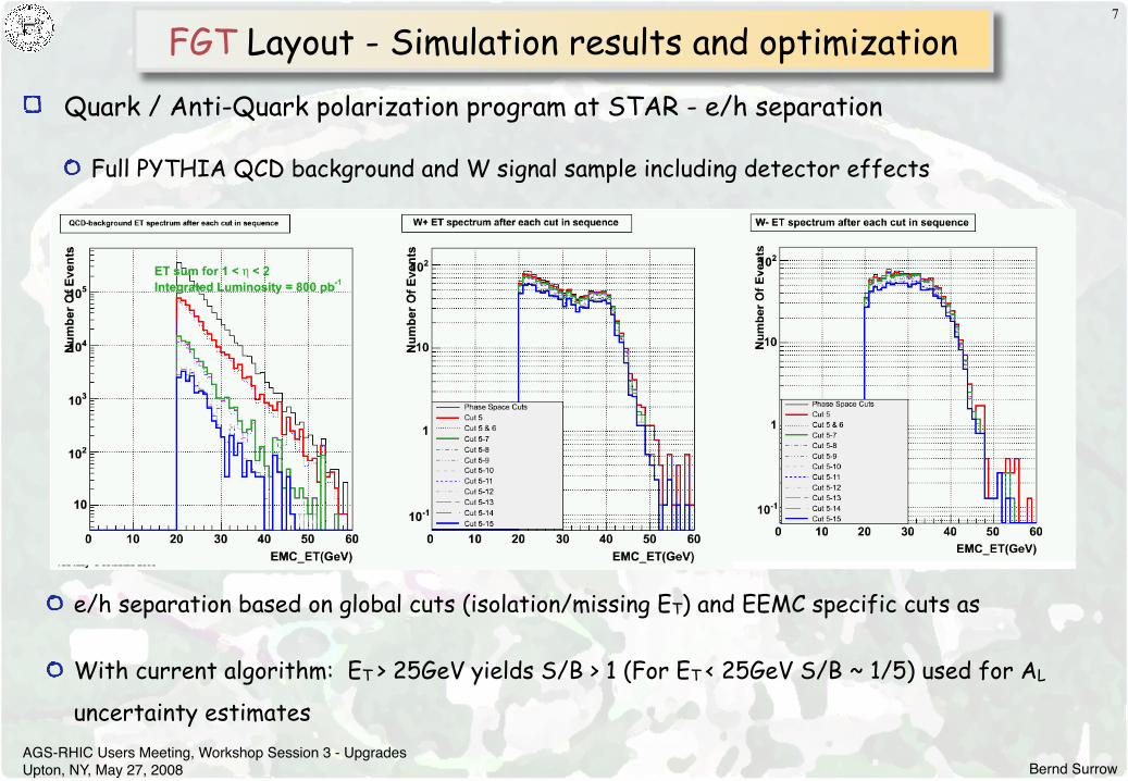
FGT Layout - Simulation results and optimization7
Quark / Anti-Quark polarization program at STAR - e/h separation
Full PYTHIA QCD background and W signal sample including detector effects
e/h separation based on global cuts (isolation/missing ET) and EEMC specific cuts as
With current algorithm: ET > 25GeV yields S/B > 1 (For ET < 25GeV S/B ~ 1/5) used for AL
uncertainty estimates
Bernd SurrowAGS-RHIC Users Meeting, Workshop Session 3 - Upgrades Upton, NY, May 27, 2008
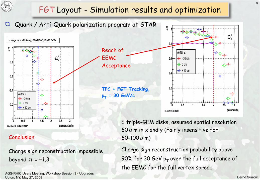
FGT Layout - Simulation results and optimization8
Conclusion:
Charge sign reconstruction impossiblebeyond η = ~1.3
TPC + FGT Tracking, pT = 30 GeV/c
6 triple-GEM disks, assumed spatial resolution 60μm in x and y (Fairly insensitive for60-100μm)
Charge sign reconstruction probability above 90% for 30 GeV pT over the full acceptance ofthe EEMC for the full vertex spread
Quark / Anti-Quark polarization program at STAR
Reach of EEMCAcceptance
Bernd SurrowAGS-RHIC Users Meeting, Workshop Session 3 - Upgrades Upton, NY, May 27, 2008
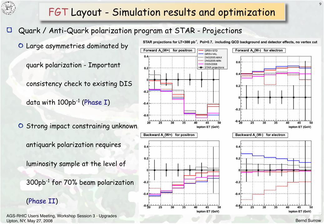
FGT Layout - Simulation results and optimization9
Quark / Anti-Quark polarization program at STAR - Projections
Large asymmetries dominated by
quark polarization - Important
consistency check to existing DIS
data with 100pb-1 (Phase I)
Strong impact constraining unknown
antiquark polarization requires
luminosity sample at the level of
300pb-1 for 70% beam polarization
(Phase II)

Bernd SurrowAGS-RHIC Users Meeting, Workshop Session 3 - Upgrades Upton, NY, May 27, 2008
FGT Technical realization
GEM technology
10
Standard layout:Pitch (P) 140 µmOuter diameter (D) 70 µmInner diameter (d) 50 µm
C. Altunbas et al., Nucl Instr. andMeth. A490 (2002) 177.
F. Sauli, Nucl Instr. andMeth. A386 (1997) 531.
Example: Triple-GEM application at COMPASS
Advantages:
Reliable (COMPASS, multi-year experience)
High gas amplification (Multiple GEMs: up to ~106)
Fast (< 20 ns FWHM, rate capability up to 105 Hz/mm)
Low mass (50µm Kapton + 10µm Cu; Thin low Z read-out
plane)
Good spacial resolution (1D and 2D) (~60µm)
Simple construction and in-expensive
Bernd SurrowAGS-RHIC Users Meeting, Workshop Session 3 - Upgrades Upton, NY, May 27, 2008
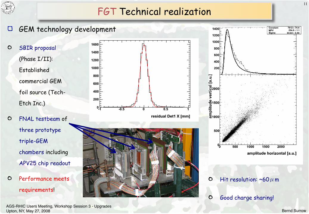
FGT Technical realization
GEM technology development
11
SBIR proposal
(Phase I/II):
Established
commercial GEM
foil source (Tech-
Etch Inc.)
FNAL testbeam of
three prototype
triple-GEM
chambers including
APV25 chip readout
Performance meets
requirements!
Hit resolution: ~60μm
Good charge sharing!
Bernd SurrowAGS-RHIC Users Meeting, Workshop Session 3 - Upgrades Upton, NY, May 27, 2008
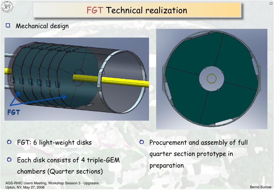
FGT Technical realization12
FGT: 6 light-weight disks
Each disk consists of 4 triple-GEM
chambers (Quarter sections)
FGT
Mechanical design
Procurement and assembly of full
quarter section prototype in
preparation
Bernd SurrowAGS-RHIC Users Meeting, Workshop Session 3 - Upgrades Upton, NY, May 27, 2008
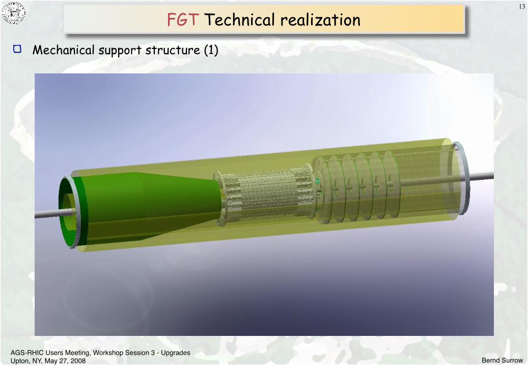
FGT Technical realization
Mechanical support structure (1)
13

Bernd SurrowAGS-RHIC Users Meeting, Workshop Session 3 - Upgrades Upton, NY, May 27, 2008
FGT Technical realization
Mechanical support structure (2)
14

Bernd SurrowAGS-RHIC Users Meeting, Workshop Session 3 - Upgrades Upton, NY, May 27, 2008
FGT Technical realization
Mechanical support structure (3)
15

Bernd SurrowAGS-RHIC Users Meeting, Workshop Session 3 - Upgrades Upton, NY, May 27, 2008
FGT Technical realization
Triple-GEM detectors - Quarter section (1)
16
Single disk
5mm Nomex honeycomb
0.25mm FR4 skins
Pins used as part of assembly and
alignment
GEM quadrant
Pins define position
Pins preserve shape
Gas manifolds and rails

Bernd SurrowAGS-RHIC Users Meeting, Workshop Session 3 - Upgrades Upton, NY, May 27, 2008
FGT Technical realization
Triple-GEM detectors - Quarter section (2)
17
HV
La
ye
r
GE
M F
oil
1
GE
M F
oil
2
GE
M F
oil
3
2D
Re
ad
ou
t L
aye
r
Component Material Radiation Length [%]
Support plate 5 mm Nomex 0.040
2x250 μm FR4 0.257
HV layer 5 μm Cu 0.035
50 μm Kapton 0.017
GEM foils 6x5 μm Cu (70%) 0.147
3x50 μm Kapton (70%) 0.036
Readout 5 μm Cu (20%) 0.007
50 μm Kapton (20%) 0.003
5 μm Cu (88%) 0.031
50 μm Kapton 0.017
5 μm Cu (10%) 0.004
0.125 mm FR4 0.064
5 μm Cu (10%) 0.004
Drift gas 10 mm CO2 (30%) 0.002
10 mm Ar (70%) 0.006
Total 0.670
Bernd SurrowAGS-RHIC Users Meeting, Workshop Session 3 - Upgrades Upton, NY, May 27, 2008
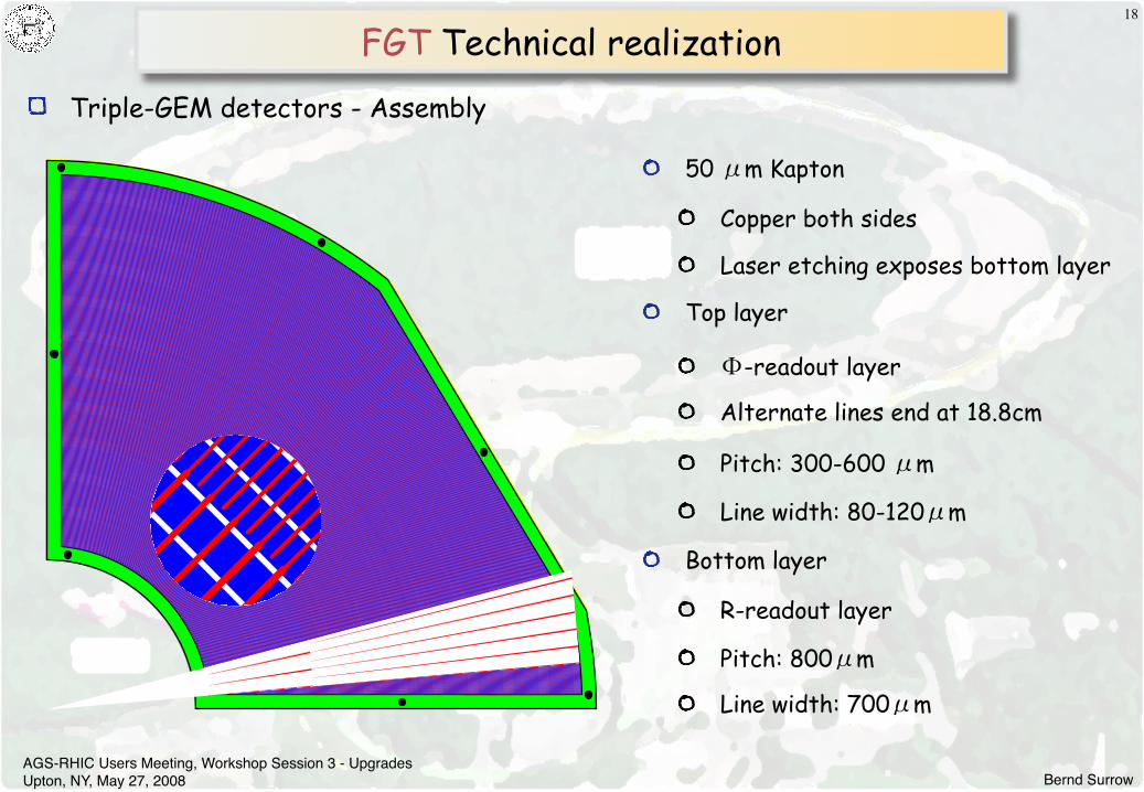
FGT Technical realization
Triple-GEM detectors - Assembly
18
50 μm Kapton
Copper both sides
Laser etching exposes bottom layer
Top layer
Φ-readout layer
Alternate lines end at 18.8cm
Pitch: 300-600 μm
Line width: 80-120μm
Bottom layer
R-readout layer
Pitch: 800μm
Line width: 700μm

Bernd SurrowAGS-RHIC Users Meeting, Workshop Session 3 - Upgrades Upton, NY, May 27, 2008
FGT Technical realization
Front-End Electronics (1)
19
Developed for CMS (75000 in CMS tracker)
and also used by COMPASS for triple-GEM
detector readout
0.25μm CMOS
128 channels
40 MHz sampling rate
4μs analogue pipeline
11:1 Signal / Noise
0.25Watt/chip
Radiation hard
Off-the shelf readout chip: APV25-S1
Used for STAR IST and FGT (1 readout system)!
8055μm
7100μm
Bernd SurrowAGS-RHIC Users Meeting, Workshop Session 3 - Upgrades Upton, NY, May 27, 2008
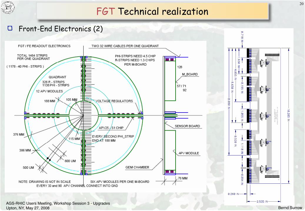
FGT Technical realization
Front-End Electronics (2)
20
Bernd SurrowAGS-RHIC Users Meeting, Workshop Session 3 - Upgrades Upton, NY, May 27, 2008
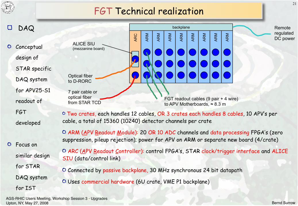
FGT Technical realization
DAQ
21
backplane
AR
C
AR
M
AR
M
AR
M
AR
M
AR
M
AR
M
AR
M
AR
M
Optical fiber to D-RORC
7 pair cable or optical fiber from STAR TCD
ALICE SIU (mezzanine board)
FGT readout cables (9 pair + 4 wire) to APV Motherboards, ≈ 8.3 m
Remote regulated DC power
Two crates, each handles 12 cables, OR 3 crates each handles 8 cables, 10 APV’s per cable, a total of 15360 (10240) detector channels per crate
ARM (APV Readout Module): 20 OR 10 ADC channels and data processing FPGA’s (zero suppression, pileup rejection); power for APV on ARM or separate new board (4/crate)
ARC (APV Readout Controller): control FPGA’s, STAR clock/trigger interface and ALICE SIU (data/control link)
Connected by passive backplane, 30 MHz synchronous 24 bit datapath
Uses commercial hardware (6U crate, VME P1 backplane)
Conceptual
design of
STAR specific
DAQ system
for APV25-S1
readout of
FGT
developed
Focus on
similar design
for STAR
DAQ system
for IST
Bernd SurrowAGS-RHIC Users Meeting, Workshop Session 3 - Upgrades Upton, NY, May 27, 2008
22
Overview - Planing
Goal: Installation in summer 2010 ⇒ Ready for anticipated first long 500GeV polarized
pp run in FY11 consistent with STAR 5-year Beam Use Request
Review: Successful review January 2008 / Beginning of construction funds FY08
Cost estimate and planing relies on the R&D and pre-design work:
Triple-GEM Detector: Complete prototype tested on the bench and during FNAL testbeam
experiment with extensive experience in mechanical design work (MIT-Bates) and assembly
including previous experience at COMPASS
Front-End Electronics (FEE) System: Complete prototype tested on the bench and during FNAL
testbeam experiment based on existing APV25-S1 readout chip (MIT-Bates)
Data Acquisition (DAQ) System: Conceptual layout is based on similar DAQ sub-detector
systems with extensive experience (ANL/IUCF)
GEM foil development: Successful development of industrially produced GEM foils through SBIR
proposal in collaboration with Tech-Etch Inc. (BNL, MIT, Yale University)
FGT Schedule / Milestones
Bernd SurrowAGS-RHIC Users Meeting, Workshop Session 3 - Upgrades Upton, NY, May 27, 2008
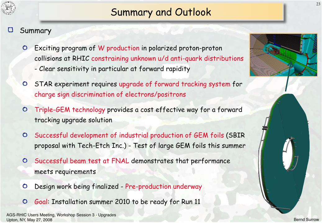
Summary and Outlook
Summary
Exciting program of W production in polarized proton-proton collisions at RHIC constraining unknown u/d anti-quark distributions - Clear sensitivity in particular at forward rapidity
STAR experiment requires upgrade of forward tracking system for charge sign discrimination of electrons/positrons
Triple-GEM technology provides a cost effective way for a forward tracking upgrade solution
Successful development of industrial production of GEM foils (SBIR proposal with Tech-Etch Inc.) - Test of large GEM foils this summer
Successful beam test at FNAL demonstrates that performance meets requirements
Design work being finalized - Pre-production underway
Goal: Installation summer 2010 to be ready for Run 11
23