the (un)official vmware vcix-nv study guidelostdomain.org/.../04/...vcix-nv-study-guide-v1.0.pdf ·...
TRANSCRIPT
The (Un)Official VMware VCIX-NV Study Guide Martijn Smit
By Martijn Smit
@smitmartijn – lostdomain.org
Welcome to the (Un)Official VMware VCIX-NV Study Guide! This guide was
compiled during the preparations of my own VCIX-NV exam, working my way
through the blueprint and blogging the notes I took per each blueprint subject.
This guide can be used for your own preparations, as a handy cookbook
reference or just for a look inside the VMware NSX solution.
If you are using this guide for preparation for your own VCIX-NV, make sure you
perform the tasks in real life and that you don’t use this guide as your only
preparation. Read the installation and configuration guides, the NSX
documentation, run the VMware Hands on Labs scenarios and read a bunch of
blogs. Best of luck!
If you are here just for the NSX fun, enjoy!
On to the good stuff. The topics below are taken from the VCIX-NV blueprint
guide version 1.7, 9 Dec 2014.

v1.0 – 05-04-2015 Page 2 of 245
Section 1 – Install and Upgrade VMware NSX
Objective 1.1 – Deploy VMware NSX Components
Objective 1.2 – Upgrade VMware NSX Components
Objective 1.3 – Configure and Manage Transport Zones
Section 2 – Create and Manage VMware NSX Virtual Networks
Objective 2.1 – Create and Administer Logical Switches
Objective 2.2 – Configure VXLANs
Objective 2.3 – Configure and Manage Layer 2 Bridging
Objective 2.4 – Configure and Manage Logical Routers
Section 3 – Deploy and Manage NSX Network Services
Objective 3.1 – Configure and Manage Logical Load Balancing
Objective 3.2 – Configure and Manage Logical Virtual Private Networks (VPNs)
Objective 3.3 – Configure and Manage DHCP/DNS/NAT
Section 4 – Perform Operational Maintenance
Objective 4.1 – Backup and Restore Network Configurations
Objective 4.2 – Monitor an NSX Implementation
Section 5 – Perform Advanced Troubleshooting
Objective 5.1 – Troubleshoot Common NSX Installation/Configuration Issues
Objective 5.2 – Troubleshoot Common NSX Component Issues
Objective 5.3 – Troubleshoot Common Connectivity Issues
Objective 5.4 – Troubleshoot Common Service Issues

v1.0 – 05-04-2015 Page 3 of 245
Section 6 – Secure an NSX Environment
Objective 6.1 – Configure and Administer Firewall Services
Objective 6.2 – Configure and Administer Role Based Access Control
Objective 6.3 – Configure and Manage Service Composer
Section 7 – Utilize API and CLI Commands to Manage an NSX Deployment
Objective 7.1 – Administer and Execute calls using the NSX vSphere API
Objective 7.2 – Manage and Report on an NSX Environment using the NSX
Command Line Interface

v1.0 – 05-04-2015 Page 4 of 245
Objective 1.1 – Deploy VMware NSX Components
Deploy the NSX Manager virtual appliance
Integrate the NSX Manager with vCenter Server
Create IP Pools
Implement and Configure NSX Controllers
Prepare Host Clusters for Network Virtualization
Implement NSX Edge Services Gateway devices
Implement Logical Routers Deploy vShield Endpoints
Implement Data Security
Deploy the NSX Manager virtual appliance
Requirements:
Working vSphere 5.5 environment (vCenter appliance, ESXi, Management
VM network).
NSX Manager Appliance.
VMware Documentation: Install the NSX Manager Virtual Appliance
Download the latest 6.0 NSX for vSphere appliance from the VMware
Downloads site.
Deploy the NSX Manager OVF
In the vSphere Web client, right click your cluster and select “Deploy
OVF Template”. Select the local file that you just downloaded.
v1.0 – 05-04-2015 Page 5 of 245
The “Review details” gives you an overview of the VM requirements and
requires you to tick “Accept extra configuration options”.
Accept the EULA (or not and continue to use legacy networking).
Select the destination VM name, vCenter folder, datastore, management
network portgroup.
Customise the NSX Manager settings and enter a password, hostname,
IP details, DNS servers and NTP servers.
Review configuration and click “Finish”.
Integrate the NSX Manager with vCenter Server
Requirements:
NSX Manager deployed and running.
VMware Documentation: Register vCenter Server with NSX Manager
Register NSX Manager to vCenter
Connect to the NSX Manager web interface via https://your.nsxmanager
Click on “Manage vCenter Registration”.
Click on the “Edit” button of the Lookup Service.
Fill out your SSO server details. Accept the certificate when asked.
After registering with SSO, click the “Edit” button for the vCenter Server.
Enter your vCenter server details. The tick “Modify plugin download
location” is only required when the NSX Manager is behind a firewall
type of masking device (don’t do that though). Also accept the SSL
certificate when proceeding.

v1.0 – 05-04-2015 Page 6 of 245
When that’s done, the Lookup Service and vCenter Server status should say
“Connected” and you should have the “Networking & Security” plugin
registered in your vCenter (the last one might require logging out and back in
again).
Create IP Pools
Requirements:
NSX Manager registered to vCenter server.
Documentation: Create an IP Pool
In order to deploy NSX Controllers, we need an IP pool where they get their IP
addresses from. This IP Pool is created in the Networking & Security plugin
under the NSX Manager we just registered.
Create an IP Pool
Navigate to Networking & Security.
Click on the “NSX Managers” menu.
Double-click on the IP address or hostname of your NSX Manager.
Select the “Manage” tab and select the “Grouping Objects” sub-tab.
Select “IP Pools” and click the “+” icon to begin adding a new IP Pool.
Give the IP Pool a name and enter the IP details (default gateway, prefix
length, DNS servers, IP Address pool) which the NSX Controllers will be
using.
Click “OK” to add the pool.

v1.0 – 05-04-2015 Page 7 of 245
This might look a bit like this:
Implement and Configure NSX Controllers
Requirements:
NSX Manager registered to vCenter server.
NSX IP Pool for NSX Controllers created.
VMware Documentation: Set Up the Control Plane
Deploy the NSX Controllers always in an odd number to avoid split-brain
situations. Deploy either 1 (only in a lab!), 3 (recommended), 5, etc., based on
scale. Current scaling of NSX can be handled by 3 NSX Controllers. After
deploying manually set up DRS anti-affinity rules to keep the controllers
running on different ESXi nodes.
v1.0 – 05-04-2015 Page 8 of 245
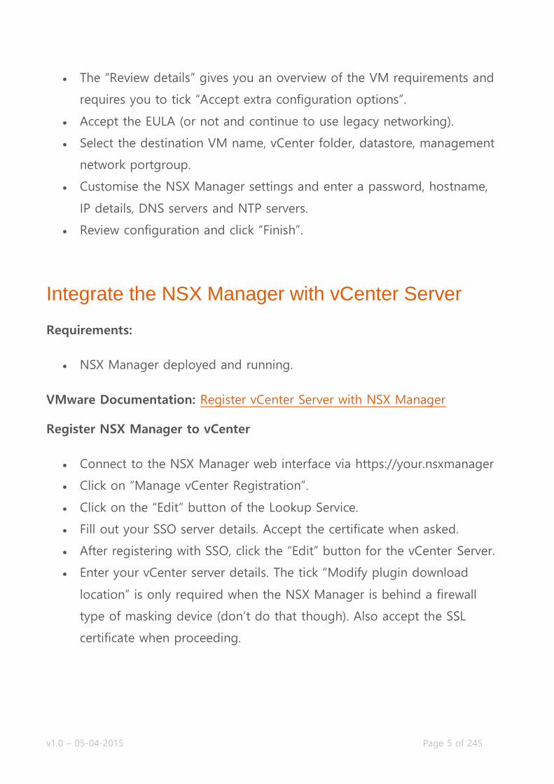
Deploy NSX Controller(s)
Navigate to Networking & Security and then the “Installation” menu.
Click on the “+” icon in the “NSX Controller Nodes” view to start the
deployment procedure.
Fill out the required details; which vCenter datacenter, cluster, datastore
you want to deploy on. Select the VM management network portgroup,
the IP Pool and the password of the controller.
Click “OK” when satisfied with your settings to start deployment.
Repeat step for the remaining NSX Controllers you would like to deploy.
The settings for deploying a NSX Controller might look like this:
v1.0 – 05-04-2015 Page 9 of 245
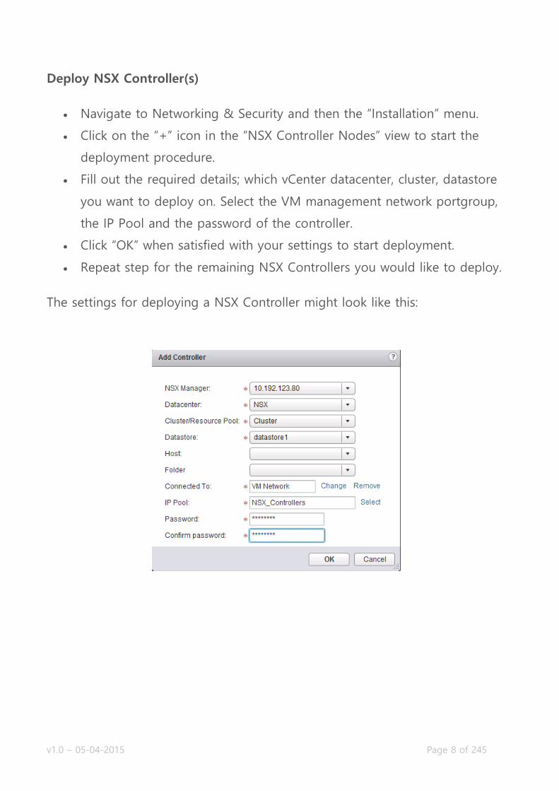
When deployed successfully, your “NSX Controller nodes” view will look like
this:
Prepare Host Clusters for Network Virtualization
Requirements:
NSX Manager registered to vCenter server.
Available distributed vSwitch for the ESXi nodes.
NSX Controller(s) deployed.
VMware Documentation: Prepare Clusters for Network Virtualization
NSX needs a bit of software (a VIB) on an ESXi node for it to be able to use
the NSX features, like the logical switch or the distributed firewall. Before you
can start using NSX, you need to install this on the ESXi nodes. Luckily, the
NSX Manager does this for you (through vCenter).
Prepare ESXi nodes
Navigate to Networking & Security and then the “Installation” menu.
Select the “Host Preparation” tab.
Select the cluster you want to use for NSX and click “Install” under
“Installation Status”
After a minute or so the installation will be complete and you’ll see a green
tick in front of your cluster. To enable the firewall module, reboot all your
nodes. After installing the NSX VIBs onto your nodes, you’ll need to configure

v1.0 – 05-04-2015 Page 10 of 245
the ESXi nodes for VXLAN. VXLAN is the backend for all your NSX networking
traffic, commonly called the “Transport Network”.
Preparing the ESXi nodes for VXLAN basically means adding a VMKernel
adapter that will be used for VXLAN communication on each ESXi node. These
VMKernel adapters require communication over IP, so they need an IP
address. You can do that in two ways; using an IP Pool or using DHCP. Both
are fine, I like to use IP Pools so that you don’t need a DHCP service and
modify the network devices to relay DHCP.
Configure VXLAN
Navigate to Networking & Security and then the “Installation” menu.
Select the “Host Preparation” tab.
Select the cluster you want to use for NSX and click “Configure” under
“VXLAN”
Select your distributed vSwitch, VLAN for the Transport network, VMKNic
IP Addressing method and the VMKNic Teaming Policy and click “OK”.
The VXLAN settings might look something like this:
v1.0 – 05-04-2015 Page 11 of 245
After a minute or so, the VMKernel adapters will be created and there will be
a green tick in the “VXLAN” column.
Implement NSX Edge Services Gateway devices
Requirements:
NSX Manager registered to vCenter server.
Prepared ESXi nodes.
VMware Documentation: Install an NSX Edge Services Gateway
VMware NSX Edge Services Gateway devices are virtual appliances that
provide several different functions to the virtual network. They can provide
Firewalling, VPN and SSL-VPN, Dynamic Routing, Load balancing and Layer 2
stretching. You can use it to define virtual network boundaries and separate
certain resources (for example different tenants). There are two types of NSX
Edges; the Edge Services Gateway and the Logical Distributed Router. The
second is discussed in the next topic. Both type Edges can be deployed in a
high availability mode, which would deploy two virtual appliances that can
take over for one and other. NSX 6.1 brings ECMP (equal cost multi pathing),
where you can deploy up to 8 Edges for a very high available solution, but as
mentioned, that is NSX 6.1 and currently not in the scope for VCIX-NV.
Deploying a NSX Edge
Navigate to Networking & Security and then the “NSX Edges” menu.
Click the “+” icon to bring up the deployment window.
v1.0 – 05-04-2015 Page 12 of 245
Select “Edge Services Gateway” as the “Install Type”, give it a name and
optional hostname, description or tenant name (used to group tenant
Edges).
Enter an username and password for the appliance(s), choose whether to
enable SSH and high availability. “Enable auto rule generation” is
recommended, as it automatically creates firewall rules when enabling
services (DHCP, VPN, etc).
Select the vCenter datacenter to deploy in, the size of your Edge
(consult the documentation for guidance).
Click the “+” icon at the “NSX Edge Appliances” view to add the virtual
appliance. Select the cluster or resource pool and the datastore to
deploy it on. Optionally select the specific ESXi node and folder.
Configure network interfaces by clicking the “+” icon in the next window
to add nics. There are two types; Internal and Uplink. Use Internal
interfaces for VM to Edge traffic and Uplink interfaces for Edge to
network traffic. Add the interfaces you want by giving it a name,
selecting the type and where it is connected to (standard vSwitch port,
dvSwitch port or Logical Switch). Add their IP addresses in the
“Configure subnets” view.
Next, configure the default gateway for the Edge.
Then optionally configure the default firewall policy and high availability
parameters.
Review your configuration and click “Finish” to start deployment.
v1.0 – 05-04-2015 Page 13 of 245
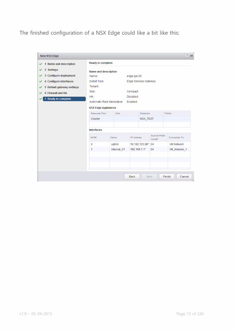
The finished configuration of a NSX Edge could like a bit like this:

v1.0 – 05-04-2015 Page 14 of 245
Implement Logical Routers
Requirements:
NSX Manager registered to vCenter server.
Prepared ESXi nodes.
VMware Documentation: Install a Logical (Distributed) Router
The second type of NSX Edge is the Logical Distributed Router, or LDR. The
LDR is a virtual appliance that can act as a router. The difference between the
Edge Services gateway is that the LDR uses the ESXi nodes as part of the
router. The LDR embed the routing information into the ESXi kernel, allowing
network traffic between two virtual machines to be routed locally inside the
ESXi node. The Edge that you deploy when setting up a LDR, is the control
machine that handles the configuration.
Deploying a Logical Distributed Router
Navigate to Networking & Security and then the “NSX Edges” menu.
Click the “+” icon to bring up the deployment window.
Select “Logical (Distributed) Router” as the “Install Type”, give it a name
and optional hostname, description or tenant name (used to group
tenant Edges).
Enter an username and password for the appliance(s), choose whether to
enable SSH and high availability.
Select the datacenter to deploy in and add the actual virtual appliance
by clicking the “+” icon in the “NSX Edge Appliances” view.
Select the cluster or resource pool and datastore to deploy in. Optionally
select an ESXi node and folder.
Select the port of the management interface of the LDR (dvSwitch port
or Logical Switch) and give it a management IP address.
v1.0 – 05-04-2015 Page 15 of 245
Then create the interfaces used for routing. VM to LDR traffic and LDR
to outside network interfaces should be added.
Next, configure the default gateway for the Edge.
Review your configuration and click “Finish” to start deployment.
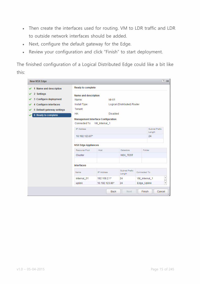
The finished configuration of a Logical Distributed Edge could like a bit like
this:
v1.0 – 05-04-2015 Page 16 of 245
Deploy vShield Endpoints
Requirements:
NSX Manager registered to vCenter server.
Prepared ESXi nodes.
IP Pool or DHCP.
VMware Documentation: Install vShield Endpoint
vShield Endpoints are service appliances which create the possibility for third-
party vendors to deliver their services inside NSX. Examples are TrendMicro
Deep Security for antivirus, Palo Alto firewalls, etc. Deploying the vShield
Endpoints is a necessary evil, but doesn’t take a lot of effort. You will need a
IP Pool specific for the vShield Endpoints before you continue, or you can give
them IP addresses using DHCP.
Deploying the vShield Endpoints
Navigate to Networking & Security and then the “Installation” menu.
Select the “Service Deployments” tab.
Click the “+” icon to start the deployment procedure.
Select “VMware Endpoint” (or “vShield Endpoint” depending on your
NSX version. In NSX 6.1 it is “Guest Introspection”) and click “Next”.
Then select the datacenter and tick the cluster to deploy in.
Select the datastore to deploy in, management network and IP
assignment method.
Review your configuration and click “Finish” to start deployment.
v1.0 – 05-04-2015 Page 17 of 245
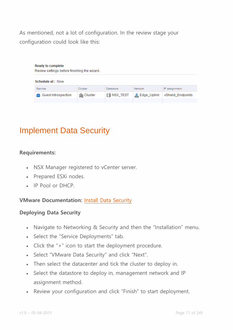
As mentioned, not a lot of configuration. In the review stage your
configuration could look like this:
Implement Data Security
Requirements:
NSX Manager registered to vCenter server.
Prepared ESXi nodes.
IP Pool or DHCP.
VMware Documentation: Install Data Security
Deploying Data Security
Navigate to Networking & Security and then the “Installation” menu.
Select the “Service Deployments” tab.
Click the “+” icon to start the deployment procedure.
Select “VMware Data Security” and click “Next”.
Then select the datacenter and tick the cluster to deploy in.
Select the datastore to deploy in, management network and IP
assignment method.
Review your configuration and click “Finish” to start deployment.

v1.0 – 05-04-2015 Page 18 of 245
In the review stage your configuration could look like this:

v1.0 – 05-04-2015 Page 19 of 245
Objective 1.2 – Upgrade VMware NSX Components
Upgrade vShield Manager 5.5 to NSX Manager 6.x
Upgrade NSX Manager 6.0 to NSX Manager 6.0.x
Upgrade Virtual Wires to Logical Switches
Upgrade vShield App to NSX Firewall
Upgrade vShield 5.5 to NSX Edge 6.x
Upgrade vShield Endpoint 5.x to vShield Endpoint 6.x
Upgrade to NSX Data Security
Upgrade vShield Manager 5.5 to NSX Manager 6.x
Requirements:
vCenter 5.5+
vShield Data Security has been uninstalled
vShield Edges 5.5+
VMware Documentation: Upgrade to NSX Manager
It is possible to upgrade vShield Manager to NSX Manager. Upgrading from
vShield to NSX keeps current virtual network configurations in place and
enabling the advanced NSX features. The upgrade process is pretty easy and
harmless, as described below.
Upgrade vShield Manager to NSX Manager
Make sure the requirements on the existing environment are met.
Get the vShield Manager Upgrade to NSX Manager bundle.
Login to the vShield Manager.
v1.0 – 05-04-2015 Page 20 of 245
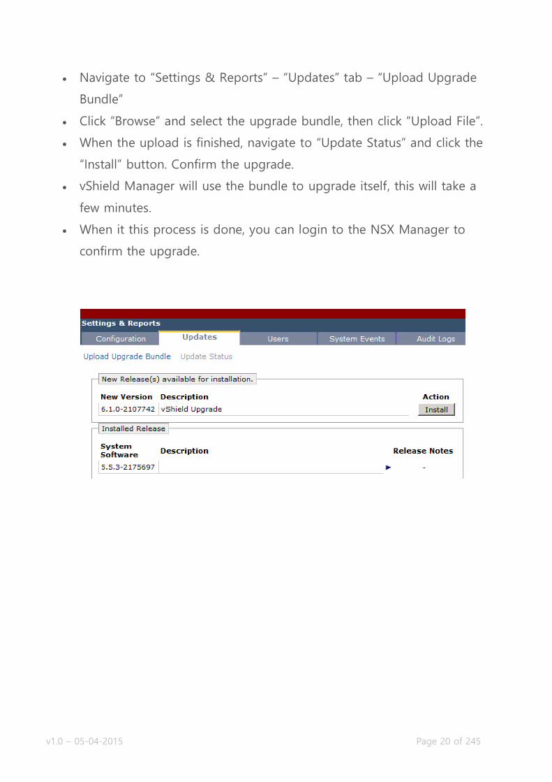
Navigate to “Settings & Reports” – “Updates” tab – “Upload Upgrade
Bundle”
Click “Browse” and select the upgrade bundle, then click “Upload File”.
When the upload is finished, navigate to “Update Status” and click the
“Install” button. Confirm the upgrade.
vShield Manager will use the bundle to upgrade itself, this will take a
few minutes.
When it this process is done, you can login to the NSX Manager to
confirm the upgrade.

v1.0 – 05-04-2015 Page 21 of 245
Upgrade NSX Manager 6.0 to NSX Manager 6.0.x
VMware Documentation: Upgrade NSX Manager from version 6.0 to 6.0.x
Upgrading NSX Manager from 6.0 to 6.0.x is as easy as pie. In the same
manner you can upgrade vShield Manager to NSX Manager, you can update
NSX Manager to the next version.
NSX Manager 6.0 to NSX Manager 6.0.x
Get the NSX Manager upgrade bundle.
Login to NSX Manager.
Navigate to “Upgrade”, press the “Upgrade” button at the top right,
select the upgrade bundle and press “Continue”.
Wait until the process completes and the login window reappears.
Login to NSX Manager and verify the version at the top right.
Upgrade Virtual Wires to Logical Switches
Requirements:
vShield Manager has been upgraded to NSX Manager.
VMware Documentation: Upgrade to Logical Switches and Install Network
Virtualization Components
Existing Virtual Wires have to be upgrades to Logical Switches to use the NSX
features. Even without Virtual Wires this procedure needs to be completed,
before NSX features can be used on the ESXi hosts. This upgrade might cause
service interruption for your Virtual Wires and ESXi hosts will be put in
v1.0 – 05-04-2015 Page 22 of 245
maintenance mode to install the NSX VIBs, so perform this during a
maintenance window.
Upgrade Virtual Wires to Logical Switches
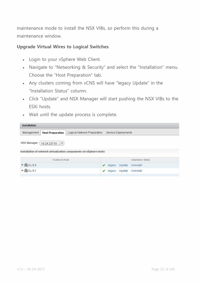
Login to your vSphere Web Client.
Navigate to “Networking & Security” and select the “Installation” menu.
Choose the “Host Preparation” tab.
Any clusters coming from vCNS will have “legacy Update” in the
“Installation Status” column.
Click “Update” and NSX Manager will start pushing the NSX VIBs to the
ESXi hosts.
Wait until the update process is complete.

v1.0 – 05-04-2015 Page 23 of 245
Upgrade vShield App to NSX Firewall
Requirements:
vShield Manager has been upgraded to NSX Manager.
vShield Apps are running version 5.5+
Your Virtual Wires have been upgrades to Logical Switches, or hosts
have been prepared.
VMware Documentation: Upgrade to NSX Firewall
Upgrading the vShield App firewall to the NSX Distributed Firewall will migrate
the existing policies. Objects with source ports will be migrated to application
sets inside NSX. When the upgrade is finished, you have to edit the policies to
make use of the newly created application sets.
Upgrade vShield App to NSX Firewall
Login to your vSphere Web Client.
Navigate to “Networking & Security” and select the “Installation” menu.
Choose the “Host Preparation” tab.
After upgrading the Virtual Wires, the “Host Preparation” tab will show
the message that the firewall is ready to upgrade.
Click the “Upgrade” button. This will take a moment.
When this process is done, the “Firewall” column should say “Enabled”.
After upgrading the firewall, check your firewall policies to make sure they are
as expected and make any corrections if needed. Also move the object groups
to the global scope instead of the policy scope.

v1.0 – 05-04-2015 Page 24 of 245
Upgrade vShield 5.5 to NSX Edge 6.x
Requirements:
vShield Manager has been upgraded to NSX Manager.
Virtual wires have been upgraded to NSX Logical Switches.
VMware Documentation: Upgrade to NSX Edge
Upgrade your vShield appliances to NSX Edge appliances by using the
following procedure.
Upgrade vShield to NSX Edge
Login to your vSphere Web Client.
Navigate to “Networking & Security” and select the “NSX Edge” menu.
The actions menu will display “Upgrade”, click that.
After the upgrade is complete, verify the upgrade by checking the
version and deploy status next to the NSX Edges.
v1.0 – 05-04-2015 Page 25 of 245
Upgrade vShield Endpoint 5.x to vShield Endpoint 6.x
Requirements:
A Distributed vSwitch has been created and all hosts are connected to it.
vShield Manager has been upgraded to NSX Manager.
Virtual wires have been upgraded to NSX Logical Switches.
VMware Documentation: Upgrade vShield Endpoint
Upgrade vShield Endpoint 5.x to 6.x
Login to your vSphere Web Client.
Navigate to “Networking & Security” and select the “Installation” menu.
Choose the “Service Deployments” tab.
Click the “Upgrade Available” option next to your vShield Endpoints.
Select the target datastore and network during the upgrade window.
Upgrade to NSX Data Security
VMware Documentation: Upgrade to NSX Data Security
There is no upgrade path available for NSX Data Security. You have to
uninstall the old vShield Data Security before upgrading to NSX, so before you
even start an upgrade to NSX; remove Data Security. If you upgraded vShield
Manager to NSX Manager without removing Data Security, you can only
remove it using a REST API call to uninstall it.
Data Security policies and reports are migrated to the vSphere Web Client,
however scanning is only possible after uninstalling vShield Data Security and
installing vSphere Data Security 6.0.

v1.0 – 05-04-2015 Page 26 of 245
Objective 1.3 – Configure and Manage Transport Zones
Create Transport Zones
Configure the control plane mode for a Transport Zone
Add clusters to Transport Zones
Remove clusters from Transport Zones
What is the Transport Zone?
The Transport Zone is the heart of the VXLAN network. It is the network where
the Logical Switches (previously known as portgroups) send their data traffic. It
is the network where the ESXi nodes create tunnels between themselves for
the VXLAN termination, making each ESXi node a VTEP. The transport zone
can span one or more vSphere clusters and your NSX environment can
contain just one or more transport zones.
v1.0 – 05-04-2015 Page 27 of 245
There are three modes a transport zone can operate in: Multicast, Unicast and
Hybrid. This mode reflects on how NSX will replicate the VXLAN data (VTEP,
ARP and MAC) between ESXi nodes.
Multicast mode is the recommended mode and uses the underlying network
for VXLAN replication, which requires multicast configuration (PIM, IGMP) on
the underlying network.
Unicast mode is where the VXLAN replication is handled by the NSX
controllers. This is where the NSX controllers control and distribute the VXLAN
data to the ESXi clusters inside the configured transport zone. Unicast mode
does not require changes to the underlying network, but is not as efficient as
using multicast.
Hybrid mode is a combination of unicast and multicast replication. Locally
inside the same first-hop switch will contain multicast replication and between
multiple switches the NSX controllers will replicate through unicast. Physical
switches need to have IGMP snooping configured, but there is no need for
multicast routing (PIM).
Create Transport Zones
Requirements:
NSX Manager and NSX controller(s) installed.
VMware Documentation: Add a Transport Zone
Add a Transport Zone
Login to your vSphere Web Client.
Navigate to “Networking & Security” and select the “Installation” menu.
Choose the “Logical Network Preparation” tab.

v1.0 – 05-04-2015 Page 28 of 245
Select the “Transport Zones” sub-tab and click the “+” icon to start
adding a transport zone.
Give the new transport zone a name and an optional description, select
the type replication and tick the clusters it will be servicing.
Click “OK”.
v1.0 – 05-04-2015 Page 29 of 245
Configure the control plane mode for a Transport Zone
Requirements:
Existing Transport Zone to modify.
VMware Documentation: View and Edit a Transport Zone
Once you created a transport zone with a specific replication mode, you have
the option to change that replication mode. If underlying network
requirements change over time, it is possible to migrate the VXLAN replication
method this way.
Change control plane mode
Login to your vSphere Web Client.
Navigate to “Networking & Security” and select the “Installation” menu.
Choose the “Logical Network Preparation” tab.
Select the “Transport Zones” sub-tab and right click the transport zone
you want to modify, choose “Edit Settings”.
Select the new replication mode for this transport zone.
Also tick the option “Migrate existing Logical Switches to the new
control plane mode”. If you do not, you will have a mix of replication
modes; the existing Logical Switches will remain using the previous
replication mode and newly created Logical Switches will start using the
new replication mode. Don’t do this without a very good reason, it will
get messy.
Click “OK”.

v1.0 – 05-04-2015 Page 30 of 245
Add clusters to Transport Zones
Requirements:
New cluster with prepared ESXi nodes.
Existing Transport Zone to extend.
VMware Documentation: Expand a Transport Zone
Newly created clusters are not included in a Transport Zone by default; you
need to manually add any new clusters. Prepare the cluster in the “Host
Preparation” tab of the “Installation” menu. The process of adding the new
cluster to an existing Transport Zone is described below.
v1.0 – 05-04-2015 Page 31 of 245
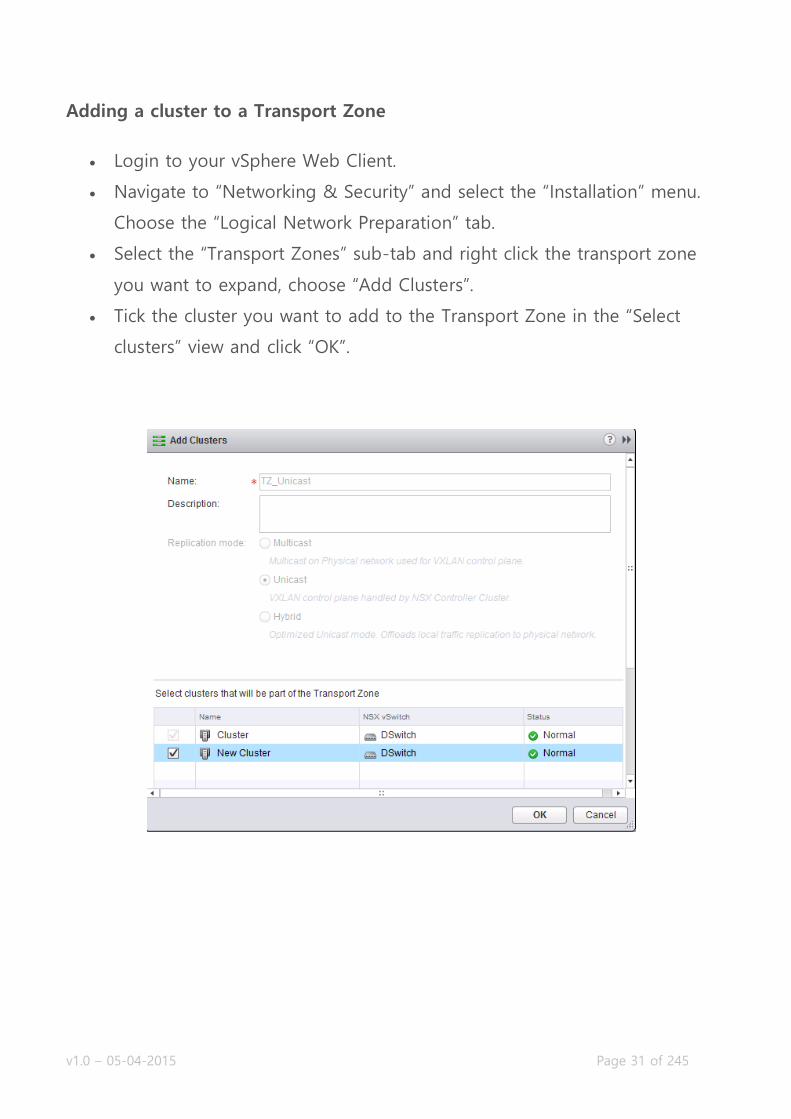
Adding a cluster to a Transport Zone
Login to your vSphere Web Client.
Navigate to “Networking & Security” and select the “Installation” menu.
Choose the “Logical Network Preparation” tab.
Select the “Transport Zones” sub-tab and right click the transport zone
you want to expand, choose “Add Clusters”.
Tick the cluster you want to add to the Transport Zone in the “Select
clusters” view and click “OK”.

v1.0 – 05-04-2015 Page 32 of 245
Remove clusters from Transport Zones
Requirements:
Existing Transport Zone with cluster to remove.
VMware Documentation: Contract a Transport Zone
When phasing out a cluster, you will need to manually remove this cluster
from the Transport Zone it is a part of, before deleting the cluster. Make sure
the cluster no longer has virtual machines connected to Logical Switches when
doing this (you will get a warning about this as well).
Removing a cluster from a Transport Zone
Login to your vSphere Web Client.
Navigate to “Networking & Security” and select the “Installation” menu.
Choose the “Logical Network Preparation” tab.
Select the “Transport Zones” sub-tab and right click the transport zone
you want the cluster removed from, choose “Remove Clusters”.
Tick the cluster you want to remove from the Transport Zone in the
“Select clusters” view and click “OK”.

v1.0 – 05-04-2015 Page 33 of 245
Objective 2.1 – Create and Administer Logical Switches
Create/Delete Logical Switches
Assign and configure IP Addresses
Connect a Logical Switch to an NSX Edge
Deploy services on a Logical Switch
Connect/Disconnect virtual machines to/from a Logical Switch
Test Logical Switch connectivity
What is a Logical Switch?
In previous versions of vSphere, you had two networking options for virtual
machines, which were a portgroup on a standard vSwitch or a portgroup on a
Distributed vSwitch. These usually consisted of a logical wire mapped to a
specific VLAN on the physical network. This way, you can isolate virtual
machines or multiple tenants from each other. The NSX Logical Switch also
creates a logical separation between different logical switches, but uses the
VXLAN technology to realise this.
This means the underlay network merely consists of 1 VLAN for the data
transport (or even routed subnets), where VXLAN facilitates the network
isolation between different logical switches. This allows the administrators to
create separated networks for virtual machines on the fly.
The logical switches are created inside Transport Zones, which in turn spans
the logical switches across all clusters that a transport zone contains. A logical
switch gets a dedicated VXLAN number for traffic identification. This number
comes from the Segment ID pool which you need to configure before creating
any logical switches.

v1.0 – 05-04-2015 Page 34 of 245
Create/Delete Logical Switches Requirements:
NSX Base components installed and configured.
Prepared clusters and ESXi nodes.
VMware Documentation: Add a Logical Switch
Add a Logical Switch
Login to your vSphere Web Client.
Navigate to “Networking & Security” and select the “Logical Switches”
menu.
Click the “+” icon to start adding a logical switch.
Give the new logical switch a name and an optional description; select
the transport zone you want to create this logical switch in.
Usually you should leave the replication mode as the default of the
transport zone, but you have an option to create an exception per
logical switch.
Click “OK”.

v1.0 – 05-04-2015 Page 35 of 245
Remove a Logical Switch
Before removing a logical switch; make sure there are no virtual machines
attached to the switch.
Login to your vSphere Web Client.
Navigate to “Networking & Security” and select the “Logical Switches”
menu.
Right click the logical switch you want to remove and select “Remove”.
Confirm deletion.
v1.0 – 05-04-2015 Page 36 of 245
Assign and configure IP Addresses
It’s not real clear to me what VMware means with this requirement, as nothing
is defined in the NSX documentation, any design guides or community
discussion. You can’t assign an IP address to a logical switch, as it’s simply a
layer-2-like boundary for virtual machines. Each virtual machine should have
an IP address (IPv4 or IPV6) and there should be some type of gateway
attached to the logical switch as well. The gateway can be a Logical
Distributed Router or an Edge Services gateway, which will have an IP address
as well.
I’m guessing that if you can assign IP addresses to virtual machines (method
depends on the operation system) and know how to deploy NSX Edges and
assign IP addresses there, you have met this requirement.
Connect a Logical Switch to an NSX Edge
Requirements:
Existing NSX Logical Switch.
Existing NSX Edge gateway.
VMware Documentation: Connect a Logical Switch to an NSX Edge
To enable network connectivity (routing) inside your NSX network, you need
NSX Edge gateways to build a bridge between logical switches. You can attach
either type of NSX Edge (Logical Distributed Router or Edge Services Gateway)
to a logical switch, the procedure is the same.

v1.0 – 05-04-2015 Page 37 of 245
Add a NSX Edge to a Logical Switch
Login to your vSphere Web Client.
Navigate to “Networking & Security” and select the “Logical Switches”
menu.
Select the Logical Switch to which you want to add the NSX Edge and
click the Edge icon:
Select the NSX Edge you want to add and click “Next”.
Select the interface of the NSX Edge that will be attached to the logical
switch and click “Next”.
Edit the details of the NSX Edge interface; give it a name, indicate
whether this will be an internal or an uplink port, set the default
connectivity status and optionally change the MTU size if needed.
Add IP addresses by click the “+” icon in the “Configure subnets” view.
Click the “+” icon again in the popup window to add the IP address,
select which IP address is the primary interface IP address and fill out
the prefix length of the subnet. Click “OK” when done.
Click “Next” when you’re finished with the NSX Edge interface
configuration.
Review your configuration and click “Finish” to add the NSX Edge to
your logical switch.

v1.0 – 05-04-2015 Page 38 of 245
Deploy services on a Logical Switch
Requirements:
Existing NSX Logical Switch.
Existing Service Profile.
VMware Documentation: Deploy Services on a Logical Switch
Service profiles contain third party features that can be attached to a logical
switch, the same as an Edge Services Gateway can be attached to a logical
switch. Before you can attach a service profile, you have to create it first.
Creating a service profile is out of scope for this procedure, the following only
describes the attaching of a service profile to a logical switch.

v1.0 – 05-04-2015 Page 39 of 245
Add Services to a Logical Switch
Login to your vSphere Web Client.
Navigate to “Networking & Security” and select the “Logical Switches”
menu.
Select the Logical Switch to which you want to add the Service and click
the Service icon:
Select Service from the dropdown menu in the popup window, attach
any filters if required and click “OK”.
Connect/Disconnect virtual machines to/from a Logical Switch
Requirements:
Existing NSX Logical Switch and a few virtual machines.
VMware Documentation: Connect Virtual Machines to a Logical Switch
Now to the good part, adding virtual machines to a logical switch. This is what
it is all about, adding virtual machines to the logical switch so they are able to
use the shiny new and advanced features of the NSX Edge Services Gateway
or Logical Distributed Router, or just separating their internal network traffic.
You are going to have to think a little bit different than regular portgroup
management on a VM though, as you need to do this from the logical switch,
not from the VM perspective. Usually you edit the VM, go to the network
interface and select the portgroup you want to place the VM in there. With
NSX, you do it from the Logical Switch management pane, select a logical
switch and add VMs to it.
v1.0 – 05-04-2015 Page 40 of 245
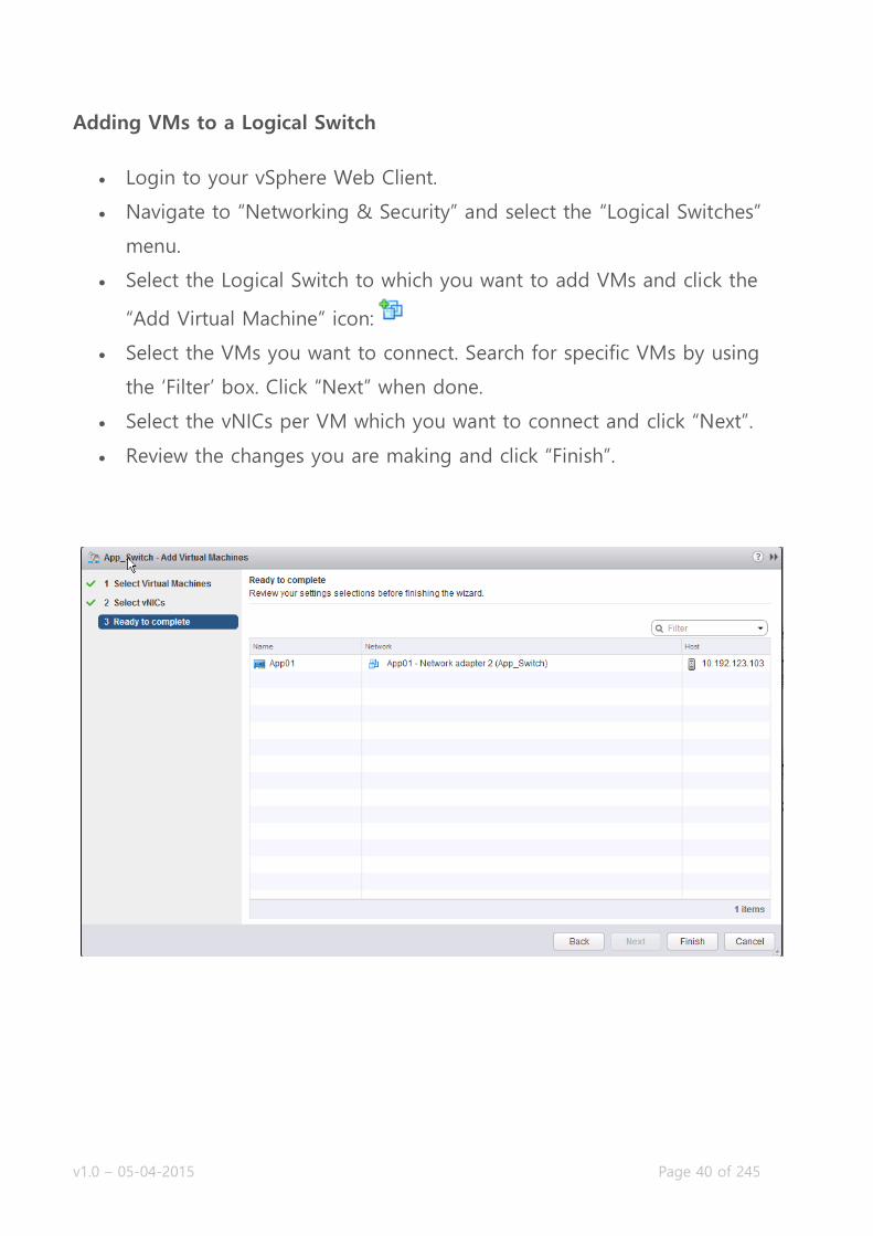
Adding VMs to a Logical Switch
Login to your vSphere Web Client.
Navigate to “Networking & Security” and select the “Logical Switches”
menu.
Select the Logical Switch to which you want to add VMs and click the
“Add Virtual Machine” icon:
Select the VMs you want to connect. Search for specific VMs by using
the ‘Filter’ box. Click “Next” when done.
Select the vNICs per VM which you want to connect and click “Next”.
Review the changes you are making and click “Finish”.
v1.0 – 05-04-2015 Page 41 of 245
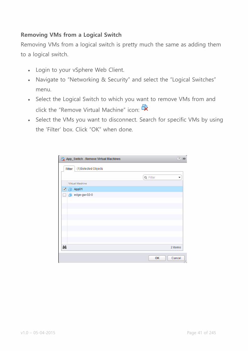
Removing VMs from a Logical Switch
Removing VMs from a logical switch is pretty much the same as adding them
to a logical switch.
Login to your vSphere Web Client.
Navigate to “Networking & Security” and select the “Logical Switches”
menu.
Select the Logical Switch to which you want to remove VMs from and
click the “Remove Virtual Machine” icon:
Select the VMs you want to disconnect. Search for specific VMs by using
the ‘Filter’ box. Click “OK” when done.

v1.0 – 05-04-2015 Page 42 of 245
Test Logical Switch connectivity
Requirements:
Existing NSX Logical Switch.
VMware Documentation: Test Logical Switch Connectivity
There are certain network requirements that a VXLAN transport network needs
to fulfil before a transport zone and the logical switches inside will actually
work. NSX provides troubleshooting tools to detect whether these
requirements have been met, or if there’s an issue somewhere. Testing the
logical switch connectivity between ESXi nodes should be a standard for
adding new logical switches.
Testing Logical Switch connectivity
Login to your vSphere Web Client.
Navigate to “Networking & Security” and select the “Logical Switches”
menu.
Click the logical switch you want to test and select the “Hosts” tab after
that.
Select a host and click “Test Connectivity” in the “More Actions” menu.
The popup window allows you to test the connectivity. The earlier
selected host will appear as Source Host and you need to select a
Destination Host.
Select the size of the test packets; the “VXLAN standard” packet is 1550
bytes.
Click “Start Test” to start testing.
After sending the test packets the result will appear below. Here is an
example of a failed test:

v1.0 – 05-04-2015 Page 43 of 245

v1.0 – 05-04-2015 Page 44 of 245
Objective 2.2 – Configure VXLANs
Prepare a cluster for VXLAN
Configure VXLAN Transport Zone parameters
Configure the appropriate teaming policy for a given implementation
VXLAN
VXLAN (or Virtual eXtensible LAN) is a widely support technology to create
logically separated network inside an existing physical network. VXLAN has a
logical limit of 16 million networks, where the modern physical network has a
limit of around 4000 (VLANs). To read a lot more about VXLAN and how it is
built, I’d like to refer you to the two-part blog of Kamau Wanguhu; VXLAN
Primer – Part 1 and VXLAN Primer – Part 2. Duncan Epping also
elaborated here.
The physical network has a few requirements to support VXLAN;
Larger MTU size; minimal 1572, 1600 is recommended.
Multicast; IGMP snooping should be enabled on the layer-2 switches and
if needed, PIM routing on the layer-3 routers.
When putting the different NSX components in perspective, the NSX Transport
Zone is the VXLAN backbone network and a Logical Switch is a VXLAN
network.
v1.0 – 05-04-2015 Page 45 of 245
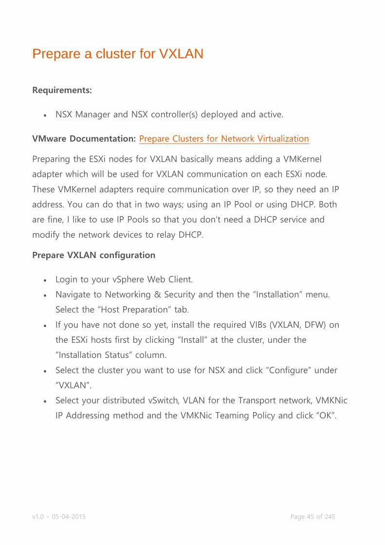
Prepare a cluster for VXLAN
Requirements:
NSX Manager and NSX controller(s) deployed and active.
VMware Documentation: Prepare Clusters for Network Virtualization
Preparing the ESXi nodes for VXLAN basically means adding a VMKernel
adapter which will be used for VXLAN communication on each ESXi node.
These VMKernel adapters require communication over IP, so they need an IP
address. You can do that in two ways; using an IP Pool or using DHCP. Both
are fine, I like to use IP Pools so that you don’t need a DHCP service and
modify the network devices to relay DHCP.
Prepare VXLAN configuration
Login to your vSphere Web Client.
Navigate to Networking & Security and then the “Installation” menu.
Select the “Host Preparation” tab.
If you have not done so yet, install the required VIBs (VXLAN, DFW) on
the ESXi hosts first by clicking “Install” at the cluster, under the
“Installation Status” column.
Select the cluster you want to use for NSX and click “Configure” under
“VXLAN”.
Select your distributed vSwitch, VLAN for the Transport network, VMKNic
IP Addressing method and the VMKNic Teaming Policy and click “OK”.

v1.0 – 05-04-2015 Page 46 of 245
Configure VXLAN Transport Zone parameters
Requirements:
Prepared cluster for NSX.
VXLAN configured for cluster.
VMware Documentation: Configure VXLAN Transport Parameters
After having configured your cluster for VXLAN, you need to specify a
Segment ID Pool. This pool of numbers is the pool where logical switches will
get their VXLAN Identifiers from. Each number (between 5000 and 16777216)
will represent an isolated network.
Setting the Segment ID Pool
Login to your vSphere Web Client.
Navigate to “Networking & Security” and select the “Installation” menu.
Choose the “Logical Network Preparation” tab.
Select the “Segment ID” sub-tab and click “Edit”.

v1.0 – 05-04-2015 Page 47 of 245
In the popup window, enter the range of IDs you want to use for your
VXLAN networks and click “OK”.
Configure the appropriate teaming policy for a given implementation
VMware Documentation: Teaming Policy for Virtual Distributed Switches
The teaming policy of uplink NICs in the distributed vSwitch which is servicing
the VXLAN backbone network should always be selected with keeping the
physical network (dual homed? meshed?) and capabilities of the hardware of
your ESXi host, so it differs per design. For instance, with UCS Blades you
cannot use LACP bundling and you should use the “Failover” option.
Below is an overview of teaming policies. Important to note is that is Source
MAC (MAC Hash) is selected, NSX will create multiple VMKNics which will
serve as VXLAN Endpoint Termination Point (VTEP).

v1.0 – 05-04-2015 Page 48 of 245
v1.0 – 05-04-2015 Page 49 of 245
Objective 2.3 – Configure and Manage Layer 2 Bridging
Add Layer 2 Bridging
Connect Layer 2 Bridging to the appropriate distributed virtual port
group
Layer-2 Bridging
When you’re talking about Logical Switches, you’re talking about a VXLAN
network. VXLAN packets and routing are handled by VTEPs, which are usually
ESXi hosts or Top-of-Rack switches. The network packets are inherently
different than regular VLAN network packets and need to be processed by a
VTEP before it can be translated into a packet which a VM understands. This
means there has to be a translation somewhere between VLAN boundaries
and VXLAN boundaries; they don’t magically understand each other.
If you run into a case where a physical server needs to be in the same subnet
as a VM running in a NSX logical switch, or if you need to use the physical
network devices as the default gateway (either a physical load balancer,
firewall or a router), or even in a migration scenario, you need to have a
translation between the logical switch VXLAN network and the VLAN they
need to be on. NSX does this with its Logical Distributed Router (LDR)
appliance.

v1.0 – 05-04-2015 Page 50 of 245
In this case, the LDR has two network interfaces; one inside the logical switch
and one inside a distributed portgroup that is inside the VLAN where we need
to be. The VLAN network traffic will have to go through the LDR control VM,
which can be prone to disruptions (ESXi host crashes). This is why the LDR
supports a high-availability deployment, where you basically deploy two LDR
control VMs which can take over for one and other.
Below we will walk through the steps needed to create a Layer-2 bridge
between a logical switch and a distributed portgroup.
v1.0 – 05-04-2015 Page 51 of 245
Add Layer 2 Bridging
Requirements:
NSX Manager and NSX controller(s) deployed and active.
Existing Logical Switch and VMs attached to it.
VMware Documentation: Add L2 Bridge
To set up a layer-2 bridge between a logical switch and a distribute
portgroup, we will create a Logical Distributed Router and configure it for
layer-2 bridging. Here’s how.
Set up a Layer-2 Bridge
Login to your vSphere Web Client.
Navigate to Networking & Security and then the “NSX Edges” menu.
Click the “+” icon to add a NSX Edge.
Select the “Logical (Distributed) Router” type, give it a name and
optional hostname, description and tenant. Click “Next”.
On the “Settings” tab, enter a username and password, determine
whether to enable SSH and if you want to enable High Availability. Click
“Next”.
Click on the “+” icon to add the details for the appliance. Select the
cluster, datastore and optional ESXi host and folder for the appliance.
Click “OK”. Click “Next” on the previous window.
Configure the management interface of the LDR. Select a network where
it should be connected and add the management IP addresses. Don’t
add any other interfaces yet and click “Next”.
Click through “Default gateway settings”, review your configuration and
click “Finish” to start building the LDR.

v1.0 – 05-04-2015 Page 52 of 245
After this, wait a moment while the LDR control VM is being deployed and
configured. When it’s done being busy, continue with building the bridge.
Double click the LDR you want to create a bridge on.
Navigate to the “Bridging” tab and click the “+” icon to create the
bridge.
In the popup window, give the bridge a name; select the logical switch
and distributed portgroup and click “OK”.
Lastly, press the button “Publish” on the top of the screen when you’re
added the bridge to push the change to the LDR.
Connect Layer 2 Bridging to the appropriate distributed virtual port group
If you have gone through the previous task, you have successfully connected a
layer-2 bridge to the appropriate distributed virtual portgroup. To make a
change to the bridge afterwards (ie. if you’ve selected the wrong distributed
portgroup), do the following:
Login to your vSphere Web Client.
Navigate to Networking & Security and then the “NSX Edges” menu.
Double click the LDR you want to modify a bridge on.

v1.0 – 05-04-2015 Page 53 of 245
Navigate to the “Bridging” tab and select the bridge you want to modify.
In the popup window, select the appropriate distributed portgroup and
click “OK”.
Lastly, press the button “Publish” on the top of the screen when you’re
added the bridge to push the change to the LDR.
v1.0 – 05-04-2015 Page 54 of 245
Objective 2.4 – Configure and Manage Logical Routers
Configure default gateway parameters
Add/Remove static routes
Configure dynamic routing protocols
o OSPF
o BGP
o IS-IS
What is a Logical Distributed Router?
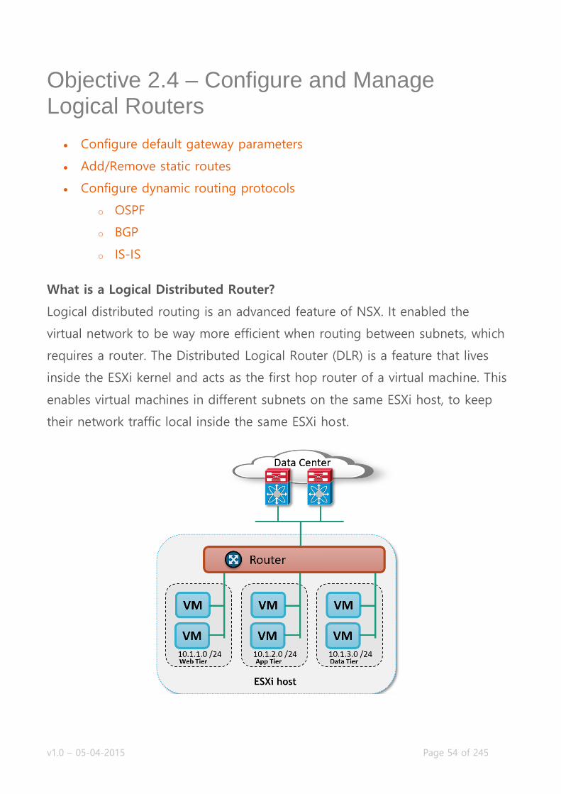
Logical distributed routing is an advanced feature of NSX. It enabled the
virtual network to be way more efficient when routing between subnets, which
requires a router. The Distributed Logical Router (DLR) is a feature that lives
inside the ESXi kernel and acts as the first hop router of a virtual machine. This
enables virtual machines in different subnets on the same ESXi host, to keep
their network traffic local inside the same ESXi host.

v1.0 – 05-04-2015 Page 55 of 245
Deploying the LDR entails deploying a virtual appliance (NSX Edge) which is
called the LDR control VM. This control VM maintains the routing data for the
attached virtual networks and virtual machines, maintains the dynamic routing
relationships (OSPF, BGP or IS-IS) and keeps the NSX controllers updated with
this information. The NSX controllers update the ESXi hosts, which do the
actual routing. Important to know is that (normally) the network traffic going
outside the virtual network, does not go through the control VM.
There are a lot of details in the logical distributed router I could go in to, but
no one explains it better than Anthony Burke in his NSX Compendium. Really
do give that a very good read and you’ll be verse in the LDR in no time. We’ll
dive in the required tasks below.
Configure default gateway parameters
Requirements:
Existing NSX Edge Logical Distributed Router.
VMware Documentation: Specify Global Configuration
When not using dynamic routing to receive external routes, you can define a
default gateway within the LDR.
Configuring default gateway
Login to your vSphere Web Client.
Navigate to “Networking & Security” and select the “NSX Edges” menu.
Choose the NSX Edge you want to modify and select the “Manage” tab.
Then select the “Routing” sub-tab and select the “Global Configuration”
sub-menu.

v1.0 – 05-04-2015 Page 56 of 245
Once there, click the “Edit” button on the right side of the “Default
gateway” table.
In the popup window, enter the default gateway details; the external
interface, gateway IP address, MTU and an optional description.
Click “OK” when done and finally click on “Publish changes” on the top
of the page.
Add/Remove static routes
Requirements:
Existing NSX Edge Logical Distributed Router.
VMware Documentation: Add a Static Route
For smaller LDR deployments, static routes might make the configuration
easier than using dynamic routing. Maintaining these static routes can be a
time consuming and sometimes confusing task, so try to keep this at a
minimal.

v1.0 – 05-04-2015 Page 57 of 245
Adding static routes
Login to your vSphere Web Client.
Navigate to “Networking & Security” and select the “NSX Edges” menu.
Choose the NSX Edge you want to modify and select the “Manage” tab.
Then select the “Routing” sub-tab and select the “Static Routes” sub-
menu.
Click the “+” icon. In the popup window, enter the destination network
in CIDR notation, next hop IP address, outgoing interface, MTU and an
optional description.
Click “OK” when done and finally click on “Publish changes” on the top
of the page.

v1.0 – 05-04-2015 Page 58 of 245
Configure dynamic routing protocols
Dynamic routing is what NSX allows to be very flexible and allow for rapid
deployment of new virtual networks, which will get propagated into the rest of
the network and activated on the fly. NSX supports three types of dynamic
routing protocols, which are basically the three most used protocols in the
modern datacenter. These protocols are: OSPF, BGP and IS-IS. Basics of these
protocols and configuration guides are below. If you’re a virtualization
administrator venturing into the networking world and want to learn more
about these protocols, there are plenty online and offline resources about
these protocols, a quick search will get you plenty.
OSPF
Requirements:
Existing NSX Edge Logical Distributed Router.
OSPF neighbor.
VMware Documentation: Configure OSPF Protocol
OSPF (or Open Shortest Path First) is a lightweight routing protocol heavily
used in datacenters. OSPF gathers link state information from available routers
and constructs a topology map of the network inside its own database and
decides routing information using that database. When configuring a LDR
instance to use OSPF, make sure you have an OSPF-capable neighbor (usually
the NSX Edge Services Gateway) inside the same network that the LDR is in.
Also create a network design for OSPF (areas, authentication, route
redistribution) before beginning with this configuring.
v1.0 – 05-04-2015 Page 59 of 245
Important definitions to know, before beginning:
Forwarding Address: This IP address will be used by the LDR to forward
network traffic and is shared by the ESXi hosts. This one should exist on an
interface attached to the LDR.
Protocol Address: This IP address is used by the LDR control VM to maintain
the peering connections.
Configuring OSPF on the LDR
Login to your vSphere Web Client.
Navigate to “Networking & Security” and select the “NSX Edges” menu.
Choose the NSX Edge you want to modify and select the “Manage” tab.
Then select the “Routing” sub-tab and select the “Global Configuration”
sub-menu.
Click the “Edit” button on the “Dynamic Routing Configuration” table.
Select a “Router ID” and whether or not you want to log dynamic
routing events. The Router ID can be an interface address or a fictional
IP address you make up.
Click “Publish changes” on the top of the page and navigate to the
“OSPF” sub-menu.
Click the “Edit” button at the top right corner. Tick “Enable OSPF” and fill
out the “Protocol” and “Forwarding” addresses and click “OK”.
In the view called “Area Definitions”, click the “+” icon to add an area.
In the popup window, enter the area ID, type (normal or NSSA) and
whether you would like to have authentication (the “Value” field is the
password) between the OSPF peers. Like regular network equipment,
NSX supports area IDs of numeric value of IP address format. Click “OK”.
In the view called “Area to Interface mappings”, click the “+” icon.

v1.0 – 05-04-2015 Page 60 of 245
Select the interface and the matching area ID and optional timer
settings. Adjust the timer settings to the OSPF neighbor or leave them
as default if you’re peering with another NSX Edge. Click “OK”.
Click “OK” when done and finally click on “Publish changes” on the top
of the page.

v1.0 – 05-04-2015 Page 61 of 245
Once your configuration is done, you can verify the OSPF peering status by
logging into the LDR management console (KVM or SSH) and executing the
following commands:
show ip ospf neighbors
show ip route ospf
The exact output depends on your network configuration, but it should look a
bit like this:
BGP
Requirements:
Existing NSX Edge Logical Distributed Router.
BGP neighbor.
VMware Documentation: Configure BGP Protocol
Border Gateway Protocol (or BGP) is a dynamic routing protocol usually found
at the edge of your network, peering with transit providers or public peers
sharing their network routes. For internal network use, it can be rather slow.
The convergence speed depends on your timer configuration, but generally
speaking: BGP is for scale, not for convergence speed.
v1.0 – 05-04-2015 Page 62 of 245
BGP works with Autonomous Systems (AS) which identify a network. When
using it in your internal network, they usually say you’re using iBGP (internal
BGP, as opposed to external BGP (eBGP)). When creating a peering between
routers, you can define prefix filters which determine which IP prefixes
(subnets) are accepted or rejected by the router and which IP prefixes are sent
out to the neighbors. You can also secure a peering with a password.
NSX supports BGP on the LDR and on the ESG, but my personal
recommendation is to stick with OSPF or IS-IS for internal peerings (unless
your networking team requires otherwise).
Adding a BGP Neighbor
Login to your vSphere Web Client.
Navigate to “Networking & Security” and select the “NSX Edges” menu.
Choose the NSX Edge you want to modify and select the “Manage” tab.
Then select the “Routing” sub-tab and select the “Global Configuration”
sub-menu.
Click the “Edit” button on the “Dynamic Routing Configuration” table.
Select a “Router ID” and whether or not you want to log dynamic
routing events. The Router ID can be an interface address or a fictional
IP address you make up.
Click “Publish changes” on the top of the page and navigate to the
“BGP” sub-menu.
Click the “Edit” button at the top right corner. Tick “Enable BGP” and fill
out the “Local AS” field with the desired Autonomous System (AS)
number and click “OK”.
Next, define a BGP peer. In the “Neighbors” table, click the “+” icon to
start adding a BGP peer.
Enter the peer details. “IP Address” is the IP of the remote peer.
“Forwarding” and “Protocol” IP addresses are the same as in the OSPF

v1.0 – 05-04-2015 Page 63 of 245
configuration. Enter the “Remote AS” local to the remote peer.
Optionally enter a customized weight, keep alive and hold down timers.
Also provide an optional peering password and IP filters. Click “OK”
when you’re done.
Click “OK” when done and finally click on “Publish changes” on the top
of the page.
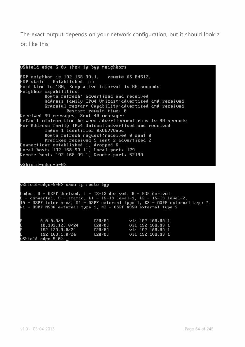
Once your configuration is done, you can verify the BGP peering status by
logging into the LDR management console (KVM or SSH) and executing the
following commands:
show ip bgp neighbors
show ip route bgp
v1.0 – 05-04-2015 Page 64 of 245
The exact output depends on your network configuration, but it should look a
bit like this:

v1.0 – 05-04-2015 Page 65 of 245
IS-IS
Requirements:
Existing NSX Edge Logical Distributed Router.
IS-IS neighbor.
VMware Documentation: Configure IS-IS Protocol
The Intermediate System to Intermediate System (IS-IS) is a widely used
protocol as underlay dynamic routing protocol. Examples are Ciscos Overlay
Transport Virtualization and FabricPath.
Configuring IS-IS
Login to your vSphere Web Client.
Navigate to “Networking & Security” and select the “NSX Edges” menu.
Choose the NSX Edge you want to modify and select the “Manage” tab.
Then select the “Routing” sub-tab and select the “Global Configuration”
sub-menu.
Click the “Edit” button on the “Dynamic Routing Configuration” table.
Select a “Router ID” and whether or not you want to log dynamic
routing events. The Router ID can be an interface address or a fictional
IP address you make up.
Click “Publish changes” on the top of the page and navigate to the “IS-
IS” sub-menu.
Click the “Edit” button at the top right of the page. In the popup
window, tick “Enable IS-IS”, enter a “System ID“, select the “IS Type” and
enter a domain and area password. Click “OK” when you’re done.
In the “Areas” view, click “Edit” to define the IS-IS areas. Click “OK when
you’re done.
Next, activate an interface for IS-IS by clicking the “+” icon at the
“Interface Mapping” table.

v1.0 – 05-04-2015 Page 66 of 245
Select the interface, the “Circuit Type” and optionally enter the different
timers to tweak the IS-IS behavior.
Click “OK” when done and finally click on “Publish changes” on the top
of the page

v1.0 – 05-04-2015 Page 67 of 245
Objective 3.1 – Configure and Manage Logical Load Balancing
Configure the Load Balancer service
Create/Modify/Remove a service monitor
Create/Modify/Remove a server pool
Create/Modify/Remove an application profile and rules
Create/Modify/Remove virtual servers
Load Balancing inside NSX
VMware NSX supplies a basic form of load balancing, which can enabled and
configured inside the NSX Edge Services Gateway. It can provide you with
basic load balancing tasks and it is mostly used to enable the scaling out of
web applications on multiple web virtual machines.
If the basic form of the NSX Load Balancer does not fit your requirements
because you need advanced rulesets, health check scripting, GSLB and other
features, the VMware NSX Partner Ecosystem will be able to help you out.
Among others, F5, Citrix and Radware have integration between NSX and their
products, so you can take advantage of their products and closely tie them in
to NSX.

v1.0 – 05-04-2015 Page 68 of 245
http://roie9876.wordpress.com/
The Load Balancing feature in the ESG can be deployed using a few methods:
One-armed mode (or proxy mode)
The ESG lives inside the virtual machine network and proxies the traffic to the
web virtual machines from its own IP address, so the web virtual machines
reply directly to the ESG. The ESG then forwards the response to the client.
The traffic flow goes as following:
User connects to an IP address that lives in the ESG (virtual-IP or VIP).
The ESG performs a destination NAT to replace the VIP with one of the
web servers in the configured pool. It also performs a source NAT to
replace the users IP address with its own IP address.
The ESG forwards the request to the web server.
The web server replies to the ESG, because the ESG replaced the users IP
address with its own.
The ESG relays the web servers response to the user.

v1.0 – 05-04-2015 Page 69 of 245
This configuration is possibly the fastest configuration to deploy, but it has a
few draw backs. The first being that the web server does not see the original
user as the incoming IP address, which has an impact on traffic analysis. To be
fair, it is a widely used configuration and the user IP is not entirely lost as you
can enabled an option called “Insert X-Forwarded-For HTTP Header” – which
make the ESG send the user IP along in the HTTP headers, which the web
server can use for analysis.
Another drawback (or benefit, depending on how you look at it) is that you
would need a dedicated ESG to do only load balancing. An existing ESG that is
serving as the default gateway of your web virtual machines cannot be
configured in this mode. If you want the ESG which serves as the default
gateway to handle load balancing, pick the next option:
Inline mode (or transparent mode)
With inline mode, the ESG performing the load balancing it literarily in the line
of the network traffic to the web servers. It is required that the web servers
have the inline ESG configured as their default gateway. Most logical would be
to use the ESG that is already the default gateway of the web servers. Inline
mode works as follows:
User connects to an IP address that lives in the ESG (virtual-IP or VIP).
The ESG performs a destination NAT to replace the VIP with an IP
address of the web servers in the configured pool.
The ESG forwards the request to the web server.
The web server receives the request from the ESG with the user IP as the
source and replies directly to the user.
As the web server replies to the user, the response goes through the
web servers default gateway, which is the ESG.
The ESG updates the load balancing service and forwards the response
to the uplinks.

v1.0 – 05-04-2015 Page 70 of 245
This method leaves the user (origin) IP address intact, which allows the web
servers to act on the origin and perform certain tasks (block/allow or analyze).
The drawback is that the ESG has to be in the path of the web servers, which
makes the design less flexible.
Configure the Load Balancer service
Requirements:
Existing NSX Edge Services Gateway.
VMware Documentation: Configure Load Balancer Service
Before you can configure anything related the load balancing, you need to
enable the load balancing service on the ESG you’re working with.
Enable the Load Balancer service
Login to your vSphere Web Client.
Navigate to “Networking & Security” and select the “NSX Edges” menu.
Choose the NSX Edge you want to modify and select the “Manage” tab.
Then select the “Load Balancer” sub-tab and select the “Global
Configuration” sub-menu.
Once there, click the “Edit” button on the right side of the “Load
balancer global configuration” table.
Tick “Enable Load Balancer”, tick “Logging” and set a “Log Level” if you
want it to log.
If you’re not going to use any Layer-7 features, tick “Enable
Acceleration”. This makes the ESG use the faster Layer-4 only load
balancing engine and disables any Layer-7 features.

v1.0 – 05-04-2015 Page 71 of 245
“Enable Service Insertion” is for third party load balancer vendors. When
you’re deploying such vendors product, enable this option, select the
service definition and configuration and any required configuration
needed (the window will tell you what is required) to complete the
wizard.
v1.0 – 05-04-2015 Page 72 of 245
Create/Modify/Remove a service monitor
Requirements:
Existing NSX Edge Services Gateway with Load Balancing Service
enabled.
VMware Documentation: Create a Service Monitor
Service Monitors are definitions of how a server that is being load balanced
(loadbalancee?) will be monitored whether it is alive or not and should receive
user requests. You can check for several things: a HTTP or HTTPS request, a
TCP or UDP port and an ICMP ping.
When using a HTTP(s) request, you can define the interval it will be checked,
what type of HTTP request (GET, OPTIONS or POST), what URL should be
tested and most importantly, you can define a string that should be received
back. If the response of the request is not what you would expect it to be, the
server can be taken out of the pool so it does not receive any new requests.
Using this, you can grant a page that simply spells out “OK” if all the services
are ok (if the database connection works, if the scheduled tasks are running,
etc, etc) and perform a granular health check.
Adding a Service Monitor
Login to your vSphere Web Client.
Navigate to “Networking & Security” and select the “NSX Edges” menu.
Choose the NSX Edge you want to modify and select the “Manage” tab.
Then select the “Load Balancer” sub-tab and select the “Service
Monitoring” sub-menu.
Click the “+” icon to add a service monitor.

v1.0 – 05-04-2015 Page 73 of 245
Enter a name, the interval it should be checked, the timeout and
maximal retries.
Then select the type monitor, as mentioned you can pick between HTTP,
HTTPS, TCP, ICMP, UDP.
Configure the specific monitor type parameters.
o HTTP(s): Pick the HTTP method (GET, OPTIONS or POST), expected
HTTP header (i.e. HTTP/1.1), the URL to check, “Send” can be POST
values to send and “Receive” is the response text that we’re
looking for.
o TCP/UDP: You can send specific text (“Send”) over the port and
check the reply (“Receive”).
o ICMP: Has no settings. What do you want, it’s a ping.
The “Extension” textfield can be used to extend the check with a bunch
of settings, which are defined in the manual.
Click “OK” when you’re done.
v1.0 – 05-04-2015 Page 74 of 245
To edit or remove a Service Monitor, simply select it and use the pencil or
cross icon to do what you need to do.
Create/Modify/Remove a server pool
Requirements:
Existing NSX Edge Services Gateway with Load Balancing Service
enabled.
Already added a Service Monitor.
VMware Documentation: Add a Server Pool
Server Pools are where the servers that do the work live. It is a collection of
worker server that will be attached to a virtual IP address later on. There are a
few settings that are important here, mainly the algorithm:
ROUND-ROBIN
Each server has a weight assigned to it. The requests are assigned to the
servers in the pool according to that weight. If you have a pool of 2 servers
with a weight of 50 each, they will both get 50% of the requests. If you have a
pool of 2 servers where one has a weight of 25 and the other a weight of 75,
they will respectively get 25% and 75% of the requests.
IP-HASH
The balancing is determined by a hash of the source and destination IP
address of the requests. This basically means the same user will get the same
server each request (unless that server dies).
v1.0 – 05-04-2015 Page 75 of 245
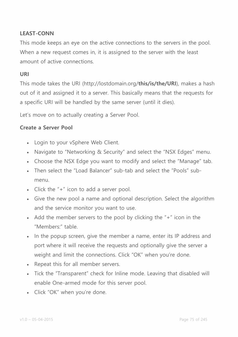
LEAST-CONN
This mode keeps an eye on the active connections to the servers in the pool.
When a new request comes in, it is assigned to the server with the least
amount of active connections.
URI
This mode takes the URI (http://lostdomain.org/this/is/the/URI), makes a hash
out of it and assigned it to a server. This basically means that the requests for
a specific URI will be handled by the same server (until it dies).
Let’s move on to actually creating a Server Pool.
Create a Server Pool
Login to your vSphere Web Client.
Navigate to “Networking & Security” and select the “NSX Edges” menu.
Choose the NSX Edge you want to modify and select the “Manage” tab.
Then select the “Load Balancer” sub-tab and select the “Pools” sub-
menu.
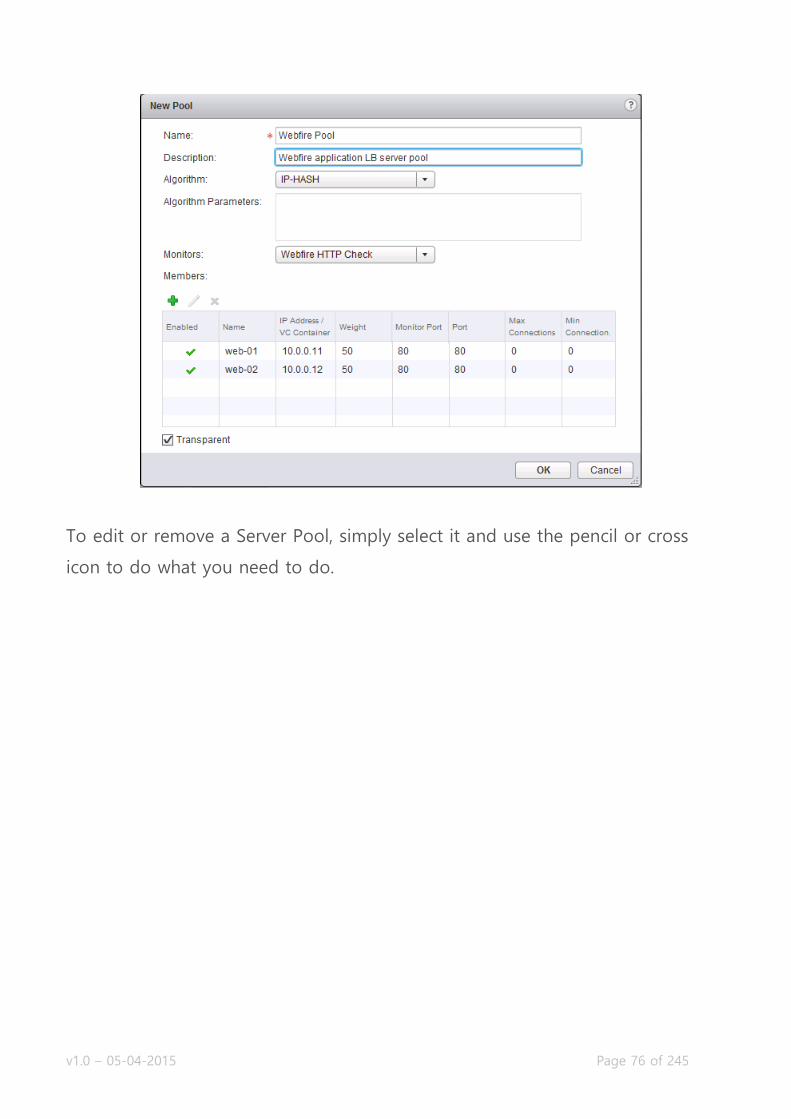
Click the “+” icon to add a server pool.
Give the new pool a name and optional description. Select the algorithm
and the service monitor you want to use.
Add the member servers to the pool by clicking the “+” icon in the
“Members:” table.
In the popup screen, give the member a name, enter its IP address and
port where it will receive the requests and optionally give the server a
weight and limit the connections. Click “OK” when you’re done.
Repeat this for all member servers.
Tick the “Transparent” check for Inline mode. Leaving that disabled will
enable One-armed mode for this server pool.
Click “OK” when you’re done.
v1.0 – 05-04-2015 Page 76 of 245
To edit or remove a Server Pool, simply select it and use the pencil or cross
icon to do what you need to do.

v1.0 – 05-04-2015 Page 77 of 245
Create/Modify/Remove an application profile and rules
Requirements:
Existing NSX Edge Services Gateway with Load Balancing Service
enabled.
VMware Documentation: Create an Application Profile, Add an Application
Rule
Application profiles are rules and settings on how the NSX Load Balancer
treats an application and what information it inserts into the request towards
the server handling the request. It specifies the persistence of a request (based
on a cookie or source IP address), configures SSL offloading (and the used SSL
certificate) or pass-through and does an optional HTTP redirect. For TCP
The way you configure these profiles are based on the requirements of your
application and therefor differ per application. You’ll need to figure out your
settings with your developer colleagues.
Create an Application Profile
Login to your vSphere Web Client.
Navigate to “Networking & Security” and select the “NSX Edges” menu.
Choose the NSX Edge you want to modify and select the “Manage” tab.
Then select the “Load Balancer” sub-tab and select the “Application
Profiles” sub-menu.
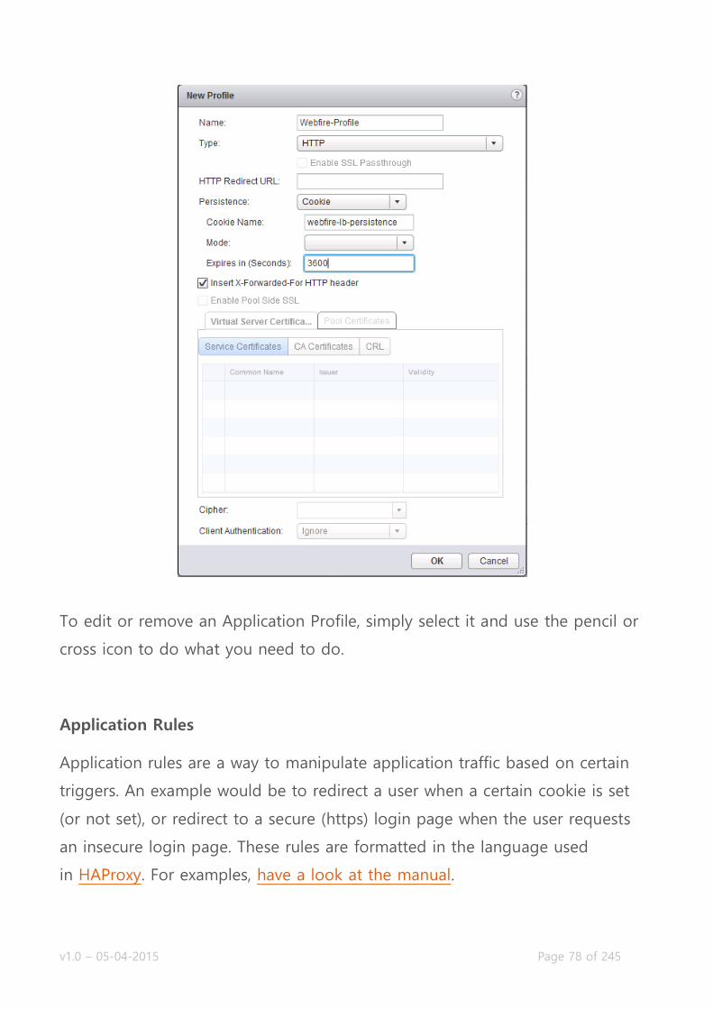
Click the “+” icon to add an application profile.
Give the profile a name and select its type. Based on the type, select the
application specific settings.
Click “OK” when you’re done.
v1.0 – 05-04-2015 Page 78 of 245
To edit or remove an Application Profile, simply select it and use the pencil or
cross icon to do what you need to do.
Application Rules
Application rules are a way to manipulate application traffic based on certain
triggers. An example would be to redirect a user when a certain cookie is set
(or not set), or redirect to a secure (https) login page when the user requests
an insecure login page. These rules are formatted in the language used
in HAProxy. For examples, have a look at the manual.
v1.0 – 05-04-2015 Page 79 of 245
Adding an Application Rule
Login to your vSphere Web Client.
Navigate to “Networking & Security” and select the “NSX Edges” menu.
Choose the NSX Edge you want to modify and select the “Manage” tab.
Then select the “Load Balancer” sub-tab and select the “Application
Rules” sub-menu.
Click the “+” icon to add a rule.
Give the rule a name and enter the rule script into the “Script” text field.
To edit or remove an Application Rule, simply select it and use the pencil or
cross icon to do what you need to do.
Create/Modify/Remove virtual servers
Requirements:
Existing NSX Edge Services Gateway with Load Balancing Service
enabled.
You’ve created an Application Profile, Service Monitor and Server Pool.
VMware Documentation: Add Virtual Servers
The virtual server is what it all is about. This is what ties it all together and
activates all your previous settings. Inside the virtual server you will find the
virtual IP address (VIP) and references to an application profile and a server
pool. When you’ve created a virtual server, you should be able to connect to
the virtual IP address and enjoy the magic of being load balanced.
Creating a Virtual Server
Login to your vSphere Web Client.

v1.0 – 05-04-2015 Page 80 of 245
Navigate to “Networking & Security” and select the “NSX Edges” menu.
Choose the NSX Edge you want to modify and select the “Manage” tab.
Then select the “Load Balancer” sub-tab and select the “Virtual Servers”
sub-menu.
Click the “+” icon to add a virtual server.
In the popup window, select the application profile; give the VIP a name
and optional description. Then select the IP address you want to use as
VIP. This IP should be already attached to the ESG.
Select the protocol you want to load balance (HTTP, HTTPS, TCP or
UDP). Enter the port number for the virtual server to listen on and select
the server pool.
Optionally give a total Connection Limit and/or a Connection Rate Limit
(per second) and click “OK” when you’re done.
Congratulations, you now have a functioning load balancer! Connect to the
virtual IP address to try it out.

v1.0 – 05-04-2015 Page 81 of 245
Objective 3.2 – Configure and Manage Logical Virtual Private Networks (VPNs)
Enable/Disable IPSec VPN Service
Configure global IPSec VPN parameters
Generate a Certificate Signing Request (CSR)
Enable and configure logging
Implement Network Access SSL VPN-Plus
o Make the ESG listen on an interface
o Add an authentication server
o Add an IP Pool
o Add a Private Network
o Add an Installation Package
o Enable the SSL VPN-Plus Service
Implement Web Access SSL VPN-Plus
Enable/Disable L2 VPN
Add and configure a L2 VPN Server
Add and configure a L2 VPN Client
Virtual Private Networks
The NSX Edge Services Gateway allows you to set up VPN tunnels between
the ESG and any VPN/IPsec capable device. There are a few different kinds of
VPN that the ESG supports: regular IPsec VPN, L2 (Layer-2) VPNs to bridge
networks and SSL-VPN for end-users.
Everyone knows regular the IPsec VPN, to create a secure connection between
two sites and route the internal subnets between those two sites. L2 VPNs are
relatively new though, allow for some pretty great migration scenarios or a
way to effortlessly burst your computing to another site (cloud hoster) using
v1.0 – 05-04-2015 Page 82 of 245
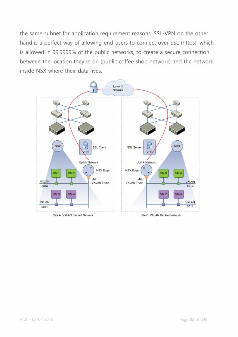
the same subnet for application requirement reasons. SSL-VPN on the other
hand is a perfect way of allowing end-users to connect over SSL (https), which
is allowed in 99.9999% of the public networks, to create a secure connection
between the location they’re on (public coffee shop network) and the network
inside NSX where their data lives.

v1.0 – 05-04-2015 Page 83 of 245
Enable/Disable IPSec VPN Service
Requirements:
Existing NSX Edge Services Gateway.
VMware Documentation: Enable IPSec VPN Service
Before configuring IPsec VPN tunnels, you need to enable the IPsec service.
This is probably the most difficult task in the entire VCIX-NV blueprint. Hang
on to your socks.
Enable the IPsec VPN service
Login to your vSphere Web Client.
Navigate to “Networking & Security” and select the “NSX Edges” menu.
Choose the NSX Edge you want to modify and select the “Manage” tab.
Then select the “VPN” sub-tab and select the “IPsec VPN” sub-menu.
Once there, click the “Enable” button.
Click the “Publish changes” button that appears.
v1.0 – 05-04-2015 Page 84 of 245
Configure global IPSec VPN parameters
Requirements:
Existing NSX Edge Services Gateway.
VMware Documentation: Specify Global IPSec VPN Configuration
Global IPsec VPN parameters consists of a default Pre-Shared Key (PSK) and
the SSL certificate the service uses for certificate authentication.
Configure default IPsec VPN settings
Login to your vSphere Web Client.
Navigate to “Networking & Security” and select the “NSX Edges” menu.
Choose the NSX Edge you want to modify and select the “Manage” tab.
Then select the “VPN” sub-tab and select the “IPsec VPN” sub-menu.
Once there, click the “Configure” link to open the global settings.
In the popup window, configure the default PSK and SSL certificate and
click “OK” when done.
Finally click the “Publish Changes” button that appears.

v1.0 – 05-04-2015 Page 85 of 245

v1.0 – 05-04-2015 Page 86 of 245
Generate a Certificate Signing Request (CSR)
Requirements:
Existing NSX Edge Services Gateway.
VMware Documentation: Working with Certificates
The NSX Edges can use SSL certificates for a bunch of things (load balancing,
IPsec VPN authentication and SSL-VPN website authenticity). I’m not going to
dive in to the workings of SSL certificates; there are a lot of resources on that.
To start the SSL certificate signing process, you need a Certificate Signing
Request. Here’s how to create a CSR in the NSX Edge.
Creating a CSR
Login to your vSphere Web Client.
Navigate to “Networking & Security” and select the “NSX Edges” menu.
Choose the NSX Edge you want to modify and select the “Manage” tab.
Then select the “Settings” sub-tab and select the “Certificates” sub-
menu.
Once there, click the “Action” menu and select “Generate CSR”.
In the popup window, enter all the required certificate details (and take
note of the details) and click “OK” when you’re done.
When the CSR is generated you will be returned to the “Certificates”
screen and you can select the CSR and copy the “PEM Encoding” for use
in the certificate request you need to file with your private Certificate
Authority (CA) or a public CA.

v1.0 – 05-04-2015 Page 87 of 245
Enable and configure logging
Requirements:
Existing NSX Edge Services Gateway.
VMware Documentation: Enable Logging for IPSec VPN
Setting up VPNs between different vendors can be tricky. Logging can save
your day there and you would be wise to enable logging at least during setup.
Enabling Logging
Login to your vSphere Web Client.
Navigate to “Networking & Security” and select the “NSX Edges” menu.
Choose the NSX Edge you want to modify and select the “Manage” tab.
Then select the “VPN” sub-tab and select the “IPsec VPN” sub-menu.
Expand “Logging Policy” and tick “Enable logging” and set a logging
level.
Click the “Publish Changes” button that appears.

v1.0 – 05-04-2015 Page 88 of 245
Implement Network Access SSL VPN-Plus
Requirements:
Existing NSX Edge Services Gateway.
VMware Documentation: Configure Network Access SSL VPN-Plus
SSL VPN-Plus inside the NSX Edge Services Gateway will allow you to grant
remote users access to the virtual network through a SSL-VPN tunnel. This
runs over https and is allowed over most public networks, so the ideal way to
set up a VPN whereever your users are. To implement SSL VPN-Plus you have
to go through a few steps, which are listed below.
Make the ESG listen on an interface
Login to your vSphere Web Client.
Navigate to “Networking & Security” and select the “NSX Edges” menu.
Choose the NSX Edge you want to modify and select the “Manage” tab.
Then select the “SSL VPN-Plus” sub-tab and select the “Server Settings”
sub-menu.
Click the “Change” button. Then in the popup window select the IPv4
Address (interface), optional IPv6 interface and the port (default 443).
Also optionally select a server certificate to use for the SSL connection.
Click “OK” when you’re done.

v1.0 – 05-04-2015 Page 89 of 245
After setting the listening IP address, you need to configure an authentication
server. This is where the ESG will perform the user authentication on and it
can be of the following types: Active Directory (AD), LDAP, RADIUS, RSA-ACE
and LOCAL authentication. The LOCAL server type will keep the authentication
locally on the ESG and you will need to submit accounts to the ESG interface.
In this example, I’ll be using an active directory server.
Add an authentication server
Move from the “Server Settings” sub-menu to the “Authentication” sub-
menu.
Then select the “Load Balancer” sub-tab and select the “Global
Configuration” sub-menu.
Click the “+” icon to add an authentication server.
Select the server type and enter all details needed. In the case of an AD
server: IP address, LDAP port, LDAP Search base, Bind DN (username),
Bind Password and the login attribute and search filter (default will be
okay there).
If you selected “LOCAL” as the authentication type, you’ll need to head
over to the “Users” sub-menu and add yourself a user to test with.
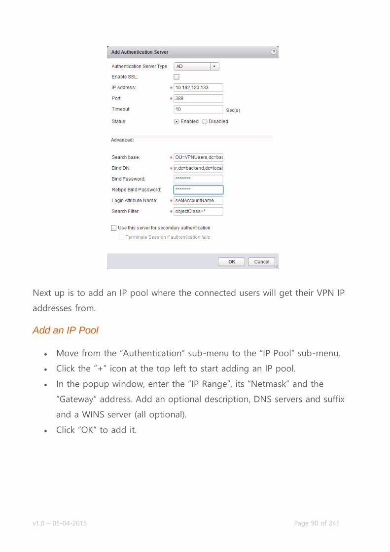
v1.0 – 05-04-2015 Page 90 of 245
Next up is to add an IP pool where the connected users will get their VPN IP
addresses from.
Add an IP Pool
Move from the “Authentication” sub-menu to the “IP Pool” sub-menu.
Click the “+” icon at the top left to start adding an IP pool.
In the popup window, enter the “IP Range”, its “Netmask” and the
“Gateway” address. Add an optional description, DNS servers and suffix
and a WINS server (all optional).
Click “OK” to add it.

v1.0 – 05-04-2015 Page 91 of 245
After giving the users an IP address from that IP Pool you just created, you
need to determine what IP networks the user needs to be able to reach over
the VPN. You can also insert exceptions for networks that need to routed over
the internet instead of through the tunnel, which is handy if you decide to
route everything over the tunnel and want to add exceptions for internet
addresses.
Add a Private Network
Move from the “IP Pool” sub-menu to the “Private Networks” sub-menu.
Click the “+” icon at the top left to start adding a private network.
In the popup window, the details of the subnet you want to include or
except in or from the VPN tunnel. In the example, I’m routing the CRM
Servers over the VPN tunnel. Click “OK” when you’re done.

v1.0 – 05-04-2015 Page 92 of 245
The last thing to do before enabling the SSL VPN-Plus service is to add an
“Installation package”. The VMware NSX SSL-VPN client is delivered in an
installer download, which you as an NSX administrator can edit to fit your
requirements. It is possible to create an installer with a predefined gateway
address, an option to run it on system startup and a bunch of other settings.
In this example, I will create a package for Windows, Linux and Mac, make it
launch on startup, the SSL network adapter will be hidden and there will be a
desktop icon.
Add an Installation Package
Move from the “Private Networks” sub-menu to the “Installation
Package” sub-menu.
Click the “+” icon at the top left to start adding a package.
In the popup window, give the package a name, add the gateway
address by clicking the “+” icon, select for which operation system it is
intended and select any other option you need. Click “OK” when you’re
done.

v1.0 – 05-04-2015 Page 93 of 245
After building the installation package, adding a private network and IP Pool,
adding an authentication method, you can go ahead and enable the SSL VPN-
Plus service.
Enable the SSL VPN-Plus Service
Move from the “Installation package” sub-menu to the “Dashboard” sub-
menu.
Click the shiny “Enable” button to enable the service.

v1.0 – 05-04-2015 Page 94 of 245
Once you’ve gone through all these steps, you should be able to browse to
the portal via a browser, login, download the installer package, install it and
login to your VPN.
v1.0 – 05-04-2015 Page 95 of 245
Implement Web Access SSL VPN-Plus
Requirements:
Existing NSX Edge Services Gateway.
SSL VPN-Plus service configured and enabled.
VMware Documentation: Configure Web Access SSL VPN-Plus
Web Access in SSL VPN-Plus is a way to share internal resources (CRM,
Sharepoint data, other web applications) through the SSL VPN-Plus interface.
A secured reverse proxy, if you will.
Adding a Web Resource
Login to your vSphere Web Client.
Navigate to “Networking & Security” and select the “NSX Edges” menu.
Choose the NSX Edge you want to modify and select the “Manage” tab.
Then select the “SSL VPN-Plus” sub-tab and select the “Web Resource”
sub-menu.
Once there, click the “+” icon to open the “Add Web Resource” popup
window.
Enter the resource name, the URL where it translates to and optionally
select the HTTP method and query parameters and a description for the
resource. Also decide to “Enable” or “Disable” it.
Click “OK” when you’re done.

v1.0 – 05-04-2015 Page 96 of 245
Enable/Disable L2 VPN
Requirements:
Existing NSX Edge Services Gateway.
VMware Documentation: Enable L2 VPN
L2 VPNs (or Layer-2 VPNs) are VPN tunnels that extend the layer-2 domain
(same subnet) across routed links. They can be established over a leased line
or even the internet. They are mostly used for migration purposes and
compute bursting. The next two chapters will show you how to configure a L2
VPN tunnel.

v1.0 – 05-04-2015 Page 97 of 245
First, we need to enable the service.
Enable the Load Balancer service
Login to your vSphere Web Client.
Navigate to “Networking & Security” and select the “NSX Edges” menu.
Choose the NSX Edge you want to modify and select the “Manage” tab.
Then select the “VPN” sub-tab and select the “L2 VPN” sub-menu.
First, set the listening IP address by clicking “Change” on the “Global
Configuration Details” table.
Select the “Listener IP” address, select the “Encryption Algorithm” and
optional change the port number and select whether to use a self-
signed certificate or a certificate you created earlier. Click “OK” when
you’re done.
Click the “Enable” button at the top of the page.
Before clicking “Publish Changes” to activate the L2 VPN service, you’ll
need to add a “Peer Site” which is described in the next chapter.

v1.0 – 05-04-2015 Page 98 of 245
Add and configure a L2 VPN Server
Requirements:
Existing NSX Edge Services Gateway.
Second NSX ESG to set up the L2 VPN with.
VMware Documentation: Add L2 VPN Server
After setting the Listener IP address, the L2 VPN server needs to be configured
with “Peer Site”. This Peer Site basically contains the authentication and
stretched interfaces.

v1.0 – 05-04-2015 Page 99 of 245
Configure a L2 VPN Server
(Assuming you’re still on the “L2 VPN” sub-menu).
Click the “+” icon on the “Site Configuration Details” table.
In the popup window, give the L2 VPN a name, optional description, a
username and password for authentication and select the stretch
interfaces (mind that only trunked interfaces are supported, so you have
to have created one).
Click “OK” when you’re done and click “Publish Changes” at the top of
the page to enable the configuration you did in the last two chapters.
v1.0 – 05-04-2015 Page 100 of 245
Add and configure a L2 VPN Client
Requirements:
Existing NSX Edge Services Gateway.
Second NSX ESG configured as a L2 VPN Server.
VMware Documentation: Add L2 VPN Client
After setting up a L2 VPN Server, you can configure an ESG as a L2 VPN Client
to create the VPN and bridge the network.
Configure a L2 VPN Client
Login to your vSphere Web Client.
Navigate to “Networking & Security” and select the “NSX Edges” menu.
Choose the NSX Edge you want to modify and select the “Manage” tab.
Then select the “VPN” sub-tab and select the “L2 VPN” sub-menu.
Click the “Enable” button at the top of the page.
Select “Client” radius in the “L2VPN Mode” selection.
Click the “Change” button on the “Global Configuration Details” table.
In the popup window, enter the server IP address, select the port
number and encryption algorithm (needs to match the servers) and
select the stretch interface. Below enter the username and password
details for authentication.
Click “OK” when you’re done.
Click “Publish Changes” to enable the configuration you just did.

v1.0 – 05-04-2015 Page 101 of 245
After setting up the L2 VPN Server and L2 VPN Client, possibly waiting a
minute or so, you should get good news by clicking the “Fetch Status” button
the L2 VPN Client or the “Show L2VPN Statistics” link on the L2 VPN Server.
The client status should look like this:

v1.0 – 05-04-2015 Page 102 of 245
Objective 3.3 – Configure and Manage DHCP/DNS/NAT
Add/Modify/Delete a DHCP IP Pool
Enable/Disable the DHCP Service
Add/Remove a DHCP Static binding
Enable/Disable DNS Services & Configure DNS Services
Add/Modify/Delete a Source NAT (SNAT) Rule
Add/Modify/Delete a Destination NAT (DNAT) Rule
DHCP, DNS and NAT services
An edge router/firewall wouldn’t be complete with services like DHCP, DNS
and NAT (source and destination), so the NSX Edge Services Gateway has
these services to complement your virtual network. There’s not much to tell
about these services, as these functionalities should be will on your resume, so
I’ll dive into the configuration.
Add/Modify/Delete a DHCP IP Pool
Requirements:
Existing NSX Edge Services Gateway.
VMware Documentation: Add a DHCP IP Pool
The ESG can provision IP addresses for virtual machines, or it can relay DHCP
requests to another DHCP service. This is how to configure an IP Pool for
DHCP to use.

v1.0 – 05-04-2015 Page 103 of 245
Add a DHCP IP Pool
Login to your vSphere Web Client.
Navigate to “Networking & Security” and select the “NSX Edges” menu.
Choose the NSX Edge you want to modify and select the “Manage” tab.
Then select the “DHCP” sub-tab and select the “Pools” sub-menu.
Click the “+” icon to add a DHCP IP Pool.
In the popup window, enter the “Start IP” and “End IP” to create the
pool. Optionally enter other details to give to the DHCP requestor; a
domain name, primary and secondary DNS server, a default gateway and
a lease time. For the lease time, you can tick “Lease Never Expires” or
give an expiration time in seconds. The “Auto Configure DNS” option will
use the DNS service configuration on the ESG for DNS on the DHCP
client.
Click “OK” when you’re done and click the “Publish Changes” button
when it appears.

v1.0 – 05-04-2015 Page 104 of 245
Enable/Disable the DHCP Service
Requirements:
Existing NSX Edge Services Gateway.
DHCP IP Pool is configured.
VMware Documentation: Enable the DHCP Service
To start the DHCP service, first configure the DHCP IP Pool as we did in the
previous chapter and then simply enable the DHCP service.
Enable DHCP Service
Login to your vSphere Web Client.
Navigate to “Networking & Security” and select the “NSX Edges” menu.
Choose the NSX Edge you want to modify and select the “Manage” tab.
Then select the “DHCP” sub-tab and select the “Pools” sub-menu.
Click the “Enable” button and determine whether you want to log the
DHCP requests.
Click the “Publish Changes” button that appears.
v1.0 – 05-04-2015 Page 105 of 245
Add/Remove a DHCP Static binding
Requirements:
Existing NSX Edge Services Gateway.
VMware Documentation: Add a DHCP Static Binding
As with other DHCP services, it is possible to create static bindings
(reservations) for statically binding MAC addresses to IP addresses when those
MAC addresses send out a DHCP request. NSX event makes it a lot easier by
allowing you to select a specific virtual machines network interface as the
binding source, which means the binding will follow the virtual machine, even
if the MAC address changes. You can just use a static MAC address as well.
Here’s how we do this:
Add a DHCP static binding
Login to your vSphere Web Client.
Navigate to “Networking & Security” and select the “NSX Edges” menu.
Choose the NSX Edge you want to modify and select the “Manage” tab.
Then select the “DHCP” sub-tab and select the “Bindings” sub-menu.
Click the “+” icon to add a binding. In the popup window, select “Use
VM NIC Binding” or “Use MAC Binding” to choose whether to make the
binding on a VM NIC basis or a static MAC address.
Once you’ve made your selection, fill out the details. In case of a VM
NIC binding, select the ESG interface, the VM itself and its NIC, enter the
hostname and IP address and optional domain name, DNS servers and
default gateway that the VM will receive.
In case of a static MAC address binding, enter the MAC address,
hostname and IP address and optionally enter a domain name, DNS
servers and a default gateway.

v1.0 – 05-04-2015 Page 106 of 245
Click “OK” when you’re done and click “Publish Changes” when it
appears.
Enable/Disable DNS Services & Configure DNS Services
Requirements:
Existing NSX Edge Services Gateway.
VMware Documentation: Configure DNS Servers
NSXs Edge Services Gateway can act as a DNS request relay service for the
virtual machines inside the local network of the ESG. The ESG uses a DNS
cache (by default 16MB) to cache DNS requests and keep them from going
outside the network and prevent extra network traffic.

v1.0 – 05-04-2015 Page 107 of 245
Configuring the DNS Service
Login to your vSphere Web Client.
Navigate to “Networking & Security” and select the “NSX Edges” menu.
Choose the NSX Edge you want to modify and select the “Manage” tab.
Then select the “Settings” sub-tab and select the “Configuration” sub-
menu.
In the “DNS Configuration” table, click the “Change” link.
In the popup window, tick “Enable DNS service” and enter the DNS
servers to which to forward the DNS requests to and a cache size in MB.
Optionally enable logging.
Click “OK” when you’re done.

v1.0 – 05-04-2015 Page 108 of 245
Add/Modify/Delete a Source NAT (SNAT) Rule
Requirements:
Existing NSX Edge Services Gateway.
VMware Documentation: Add an SNAT Rule
To transition from an internal network to an external network, source NAT is
usually used to mask the IP addresses in the internal network to the external
IP address of the router that’s between the internal and external network. The
ESG can perform this function as well, which allows the ESG to be used for
internet connections or simply to mask certain networks (for example in case
of overlapping subnets). Here’s how to mask an internal network:
Adding a SNAT rule
Then select the “NAT” sub-tab.
Click the “+” icon and select “Add SNAT Rule”.
In the popup window, select the external interface where this translation
should apply, enter the original source IP address (or range) and enter
the translated IP address (or range). Tick “Enabled” and optionally tick
“Enable logging” and click “OK” when you’re done.
The “IP/Range” can have a few different value formats: Single IP:
192.168.0.135, IP Range: 192.168.0.135-192.168.0.136 or an IP Subnet:
192.168.0.0/24
Click “Publish Changes” to activate the source NAT rule.

v1.0 – 05-04-2015 Page 109 of 245
Add/Modify/Delete a Destination NAT (DNAT) Rule
Requirements:
Existing NSX Edge Services Gateway.
VMware Documentation: Add a DNAT Rule
If your virtual network is closed off by the ESG by using source NAT to mask
the internal IP addresses to the outside, destination NAT is a way to open up
certain ports from the outside to the inside of the network. Usually used for
services that need to be reachable from the public, such as mail servers, web
applications, etc.
Adding a DNAT rule
Login to your vSphere Web Client.
Navigate to “Networking & Security” and select the “NSX Edges” menu.
Choose the NSX Edge you want to modify and select the “Manage” tab.
Then select the “NAT” sub-tab.
Click the “+” icon and select “Add DNAT Rule”.
In the popup window, select the outside interface in “Applied On:”, enter
the outside IP address in “Original IP”, select the protocol (TCP, UDP, IP

v1.0 – 05-04-2015 Page 110 of 245
and a lot more), the destination port (or any port), then enter the
destination IP address and port. Give the rule an optional description
and tick “Enabled” and optionally tick “Enable logging” to log
connections to this rule.
Click “OK” when you’re done and click “Publish Changes” when it
appears.
v1.0 – 05-04-2015 Page 111 of 245
Objective 4.1 – Backup and Restore Network Configurations
Schedule/Backup/Restore NSX Manager data
Export/Restore vSphere Distributed Switch configuration
Import/Export Service Composer profiles
Export/Import/Load Distributed Firewall configurations
Backup & Restore in NSX
When a complete NSX virtual network is built with logical switches, distributed
routers & firewalls, edge services gateways and all the virtual machine network
data, there has gone a lot of time into that configuration. As with physical
switches, you’d want to make sure that the implementation time cannot be
thrown away by some major disaster where you lose configuration and need
to do it all over again. With NSX, you can back up the networking
configuration, in case of disaster striking. The NSX Manager, Distributed
vSwitch, NSX Service Composer and the NSX Distributed Firewall all have
backup and restore options, which are covered in this post.
Schedule/Backup/Restore NSX Manager data
Requirements:
Deployed NSX Manager.
(S)FTP Server to push backups to.
VMware Documentation: Back Up Your NSX Manager Data

v1.0 – 05-04-2015 Page 112 of 245
The NSX Manager is the foundation for the NSX configuration inside the
virtual environment. You set it up to make NSX available within vCenter, it
handles the preparation of ESXi hosts and is involved in pretty much every
configuration step that is performed. This means the configuration inside the
NSX Manager is pretty important and you damn well create some backups of
it, in case of a natural disaster crippling it (software bug corrupting the
database). Luckily, the NSX Manager has the option to manually create a
backup, create a scheduled task for FTP or SFTP backups and of course, to
restore backups. This all happens in the NSX Manager interface, not the
vCenter interface, keep that in mind for the next walkthroughs.
Backup NSX Manager Setup
Login to your NSX Manager interface.
Navigate to the “Backup & Restore” page by using the big button.
First, configure the (S)FTP server the backups will be stored on by
clicking the “Change” button next to the “FTP Server Settings”.
In the popup window, enter the details of your server. Enter the IP
address or hostname, select the protocol (SFTP or FTP), the server port,
username and password details, a directory to put the backups in, a
prefix for the backup files and a pass phrase to protect the backup with
a password.
Click “OK” when you’re done.
NSX Manager will now login to (S)FTP server and check what files are
there. If it cannot connect for some reason, an error message will appear
at the top of the page. If there are existing backups on the server, they
will be displayed in the “Backup History” table.
To run a backup manually, click the “Backup” button.

v1.0 – 05-04-2015 Page 113 of 245
Now that you have set up the backup destination server and created your first
manual backup to confirm that the destination server is working as it should
be, you can configure the NSX Manager to automatically create backups with
a scheduled task.
Configure scheduled NSX Manager Backups
Login to your NSX Manager interface.
Navigate to the “Backup & Restore” page by using the big button.
Click the “Change” button next to “Scheduling:”
In the popup window, select the backup frequency (Weekly, Daily, and
Hourly). Depending on the backup frequency, you can select the day of
the week, hour of the day and minute in the hour to run the backup.
Click “Schedule” when you’re done.

v1.0 – 05-04-2015 Page 114 of 245
When first configuring the (S)FTP server, the NSX Manager will login to the
server and see if there are any existing backups in there. If you’re restoring a
NSX Manager from a backup, you can select one of those existing backups
and restore it.
Restoring a NSX Manager backup
Login to your NSX Manager interface.
Navigate to the “Backup & Restore” page by using the big button.
In the “Backup History” table, select the backup you want to restore
from (dates are displayed) and click the “Restore” button.
A popup window will ask you to confirm the restore, as it’ll interrupt
connections with the NSX Manager and redirect you to the login screen
when it is done.

v1.0 – 05-04-2015 Page 115 of 245
Export/Restore vSphere Distributed Switch configuration
Requirements:
Existing vSphere Distributed Switch to backup.
VMware Documentation: Export, Import, and Restore Distributed Switch
Configurations
The Distributed vSwitch is another integral part of a NSX environment, with
the transport zone portgroup and all logical switch virtual wire portgroups
created on the dvSwitch. A backup of the distributed vSwitch can be made
through the vSphere Web Client.
Export dvSwitch configuration
Login to your vSphere Web Client.
Navigate to “Networking” under “Inventories”.
Right click on the dvSwitch you want to backup, go down to “All vCenter
Actions” and select “Export Configuration” in the sub-menu.
In the popup window, select whether to export the dvSwitch
configuration and the created portgroups or just the dvSwitch
configuration. Also give it an optional description. Click “OK” when
you’re ready.
After creating the export, it will ask you if you want to save the exported
file. Click “Yes” to save the file on your local computer.

v1.0 – 05-04-2015 Page 116 of 245
After making a backup of a dvSwitch, you can use that saved file to restore
the configuration of a dvSwitch.
Restore dvSwitch configuration
Login to your vSphere Web Client.
Navigate to “Networking” under “Inventories”.
Right click on the dvSwitch you want to restore (create a new one if
you’re starting from scratch), go down to “All vCenter Actions” and
select “Restore Configuration” in the sub-menu.
In the popup window, select the backup file and select whether to
restore just the dvSwitch configuration or also the portgroups. Keep in
mind that existing portgroups that do not conflict will not be deleted.
Click “Next”, review your pending action and click “Finish” to perform the
restore.
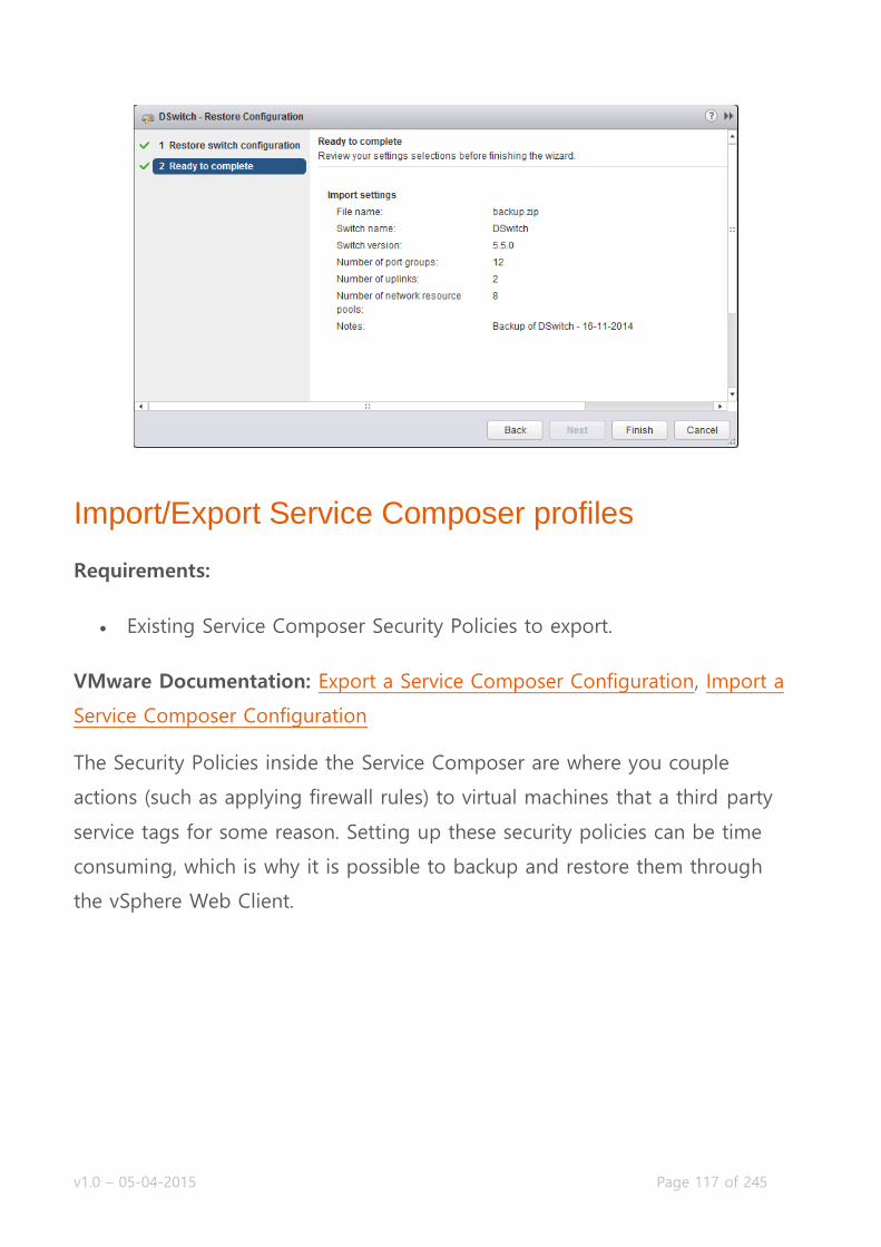
v1.0 – 05-04-2015 Page 117 of 245
Import/Export Service Composer profiles
Requirements:
Existing Service Composer Security Policies to export.
VMware Documentation: Export a Service Composer Configuration, Import a
Service Composer Configuration
The Security Policies inside the Service Composer are where you couple
actions (such as applying firewall rules) to virtual machines that a third party
service tags for some reason. Setting up these security policies can be time
consuming, which is why it is possible to backup and restore them through
the vSphere Web Client.

v1.0 – 05-04-2015 Page 118 of 245
Export a Security Policy
Login to your vSphere Web Client.
Navigate to “Networking & Security” and select the “Service Composer”
menu.
Select the “Security Policies” sub-tab and right click the security policy
you want to backup and select “Export Configuration”.
In the popup window, give the export a name, description and object
prefix. Click “Next”.
Double check the right security policy is selected and optionally select
more. Click “Next” when ready.
Review the export and click “Finish” when done. When asked, save the
export somewhere on your local computer.

v1.0 – 05-04-2015 Page 119 of 245
After creating a backup file of a security policy, you can import that policy
back into the service composer to restore the policy if it has been deleted.
Import a Security Policy
Login to your vSphere Web Client.
Navigate to “Networking & Security” and select the “Service Composer”
menu.
Select the “Security Policies” sub-tab and click on the “Import
Configuration” icon:
In the popup window, browse to the backup file by using the “Browse”
link, give the imported objects an optional prefix and click “Next”.
Review the import task and click “Finish” to start importing.
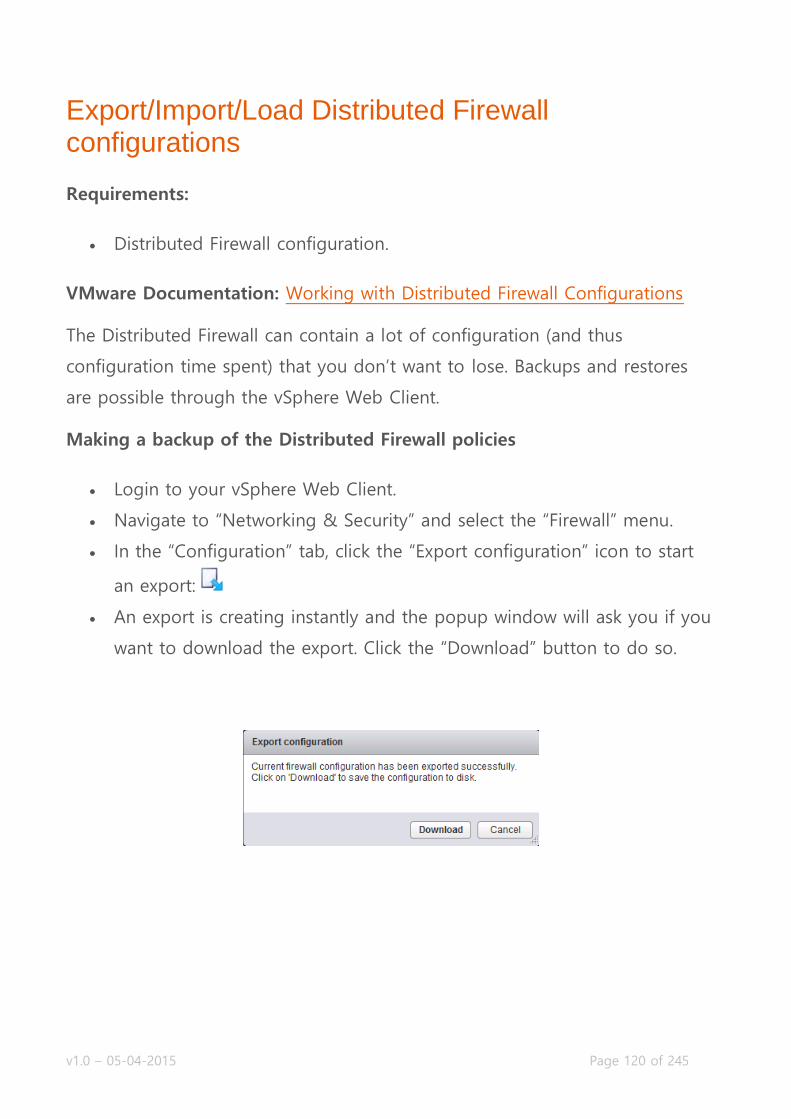
v1.0 – 05-04-2015 Page 120 of 245
Export/Import/Load Distributed Firewall configurations
Requirements:
Distributed Firewall configuration.
VMware Documentation: Working with Distributed Firewall Configurations
The Distributed Firewall can contain a lot of configuration (and thus
configuration time spent) that you don’t want to lose. Backups and restores
are possible through the vSphere Web Client.
Making a backup of the Distributed Firewall policies
Login to your vSphere Web Client.
Navigate to “Networking & Security” and select the “Firewall” menu.
In the “Configuration” tab, click the “Export configuration” icon to start
an export:
An export is creating instantly and the popup window will ask you if you
want to download the export. Click the “Download” button to do so.
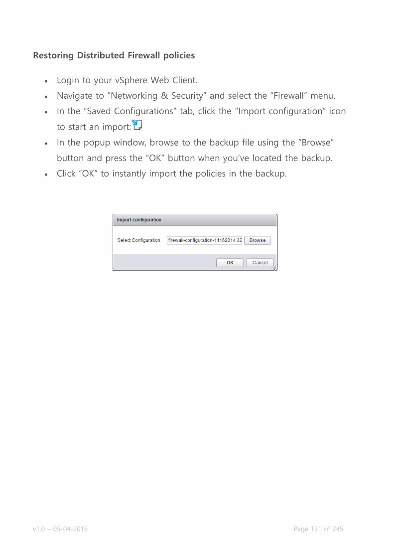
v1.0 – 05-04-2015 Page 121 of 245
Restoring Distributed Firewall policies
Login to your vSphere Web Client.
Navigate to “Networking & Security” and select the “Firewall” menu.
In the “Saved Configurations” tab, click the “Import configuration” icon
to start an import:
In the popup window, browse to the backup file using the “Browse”
button and press the “OK” button when you’ve located the backup.
Click “OK” to instantly import the policies in the backup.

v1.0 – 05-04-2015 Page 122 of 245
Objective 4.2 – Monitor an NSX Implementation
Configure and manage centralized logging for the NSX Manager and
NSX Edge devices
Create/Edit/Delete a Service Monitor
Monitor and analyze networking and security metrics with vCenter
Operations Manager
Monitor security policies with Activity Monitoring and ensure they are
being enforced correctly
Monitor and analyze traffic to and from protected virtual machines with
Flow Monitoring
Monitor statistics, counters and health of networking services
Monitor health and status of infrastructure components, such as
vSphere, NSX Manager and Control Cluster
Enable data collection for single/multiple virtual machines
Monitoring your NSX installation
As with any other platform, configuring monitoring your NSX environment
should be one of the first things you realize after it’s installed. There are
several ways to keep tabs on the NSX network, ranging from sending events
to a centralized syslog server to proactive alerts which allows you to respond
to network issues in real-time. This chapter covers several methods of using
the NSX tooling available to collect information from the NSX network.

v1.0 – 05-04-2015 Page 123 of 245
Configure and manage centralized logging for the NSX Manager and NSX Edge devices
Requirements:
NSX Environment, including NSX Edges.
VMware Documentation: NSX Manager: Specify Syslog Server, NSX Edge:
Configure Remote Syslog Servers
Storing logs in a centralized database can help correlate messages, increase
the log retention time and simply make it easier to read them and get better
intel. We start by sending the NSX Manager logs to a central syslog server.
Configuring Syslog Server in NSX Manager
Login to your NSX Manager.
Navigate to “Manage Appliance Settings”.
In the “Syslog Server” tab, click the “Edit” button.
Enter the syslog server details (IP address or hostname, network port
and protocol) and click “OK”.

v1.0 – 05-04-2015 Page 124 of 245
Each NSX Edge Gateway you deploy, also has the ability to send the
generated log entries to a central syslog server.
Configure Syslog Server on a NSX Edge
Login to your vSphere Web Client.
Navigate to “Networking & Security” and select the “NSX Edges” menu.
Choose the NSX Edge you want to modify and select the “Manage” tab.
Then select the “Settings” sub-tab and select the “Configuration” sub-
menu.
In the “Details:” table, click “Change” next to the “Syslog servers” line.
Enter the IP address or hostname in the syslog server field and click
“OK” when you’re done.
v1.0 – 05-04-2015 Page 125 of 245
Create/Edit/Delete a Service Monitor I’m pretty sure VMware means the Service Monitor inside the Edge Load
Balancer service, as there are no other references to a Service Monitor.
Managing Service Monitors was covered in the Load Balancing post.
Monitor and analyze networking and security metrics with vCenter Operations Manager You can already use vCenter Operations to monitor your virtual environment,
storage, physical network, virtual machines and applications. Using the vCops
Management Pack for NSX-vSphere, you can add NSX information to vCOps
(or “vROps: vRealize Operations” these days) to enable a full information
spectrum.
You’re encouraged to set up a test environment with vCops and the NSX
Management Pack, but for time reasons I have not been able to get my own
testlab up and running, so no live screenshots for this one.
Instead I offer an explanation from the VMware blogs:
The vC Ops Management Pack for NSX-vSphere 1.0 extends the operational
management capabilities of vCenter Operations into the areas of virtual and
physical data center networking. It provides the following operations
capabilities for virtual administrators and network operations administrators, in
highly virtualized network environments which use both vSphere and NSX
technologies:

v1.0 – 05-04-2015 Page 126 of 245
Visibility of all NSX networking services deployed within each vSphere
cluster including NSX manager, NSX controllers, and NSX data plane
services (logical switch, routers, firewalls etc.). Several different pre-
defined vCenter Operations widgets are leveraged for representing NSX
services.
Visibility of vSphere hosts in NSX transport zones, within or across
multiple vSphere clusters (for seeing the mobility and routing spans).
Search and drill down functions for obtaining the operations health of
deployed NSX objects.
Embedded dependency rules of both logical and physical networking
relationships for problem alerting and root-cause problem solving. This
includes detection and alerting of NSX configuration, connectivity, and
health problems. All alerts are consolidated into a vCenter Operations
Manager alert interface.
Extension of the core vCenter Operations Manager health and risk
analytics engine for the inclusion of NSX object key performance and
health indicators.

v1.0 – 05-04-2015 Page 127 of 245
NSX delivers a completely new operational model for networking that breaks
through current physical network barriers allowing data center operators to
achieve order of magnitude better speed, economics and choice.
Just like server virtualization enables IT to treat physical hosts as a pool of
compute capacity, the NSX approach allows IT to treat their physical network

v1.0 – 05-04-2015 Page 128 of 245
as a pool of transport capacity that can be consumed and repurposed on
demand.
For more information on NSX, please look here.
The following diagram details the NSX constructs and the Software Defined
Data Center Operational Management Solutions:
Important information for this release (Release notes, documentation and
download page) can be found at:
https://solutionexchange.vmware.com/store/products/vmware-
vcenter-operations-management-pack-for-nsx-vsphere-1-0
Source: http://blogs.vmware.com/management/2014/07/announcing-vmware-vcenter-
operations-management-pack-nsx-vsphere-1-0.html

v1.0 – 05-04-2015 Page 129 of 245
Monitor security policies with Activity Monitoring and ensure they are being enforced correctly
Requirements:
Running virtual machines with open network communication.
VMware Documentation: Activity Monitoring,View Virtual Machine Activity
Report, Enable Data Collection
The Activity Monitoring feature inside NSX is a way to monitor application
traffic inside the virtual network. This feature is about actual user connections
to applications and reports usernames, groups and all kinds of vCenter
container objects and generating reports about connections between all of
those objects.
Inside the Activity Monitoring page, you can generate reports for:
Activity between source and destination VMs and application traffic.
Inbound or outbound traffic from Active Directory groups to certain
virtual machines.
Inter Container network traffic from specific Active Directory groups to
either desktop pools or security groups (which you might remember, can
contain every type of vCenter object so the sky is the limit there)

v1.0 – 05-04-2015 Page 130 of 245
Monitor and analyze traffic to and from protected
virtual machines with Flow Monitoring
Requirements:
Running virtual machines with open network communication.
VMware Documentation: Flow Monitoring
The Flow Monitoring inside NSX is a way to generate reports or generate live
reporting of network flows going through the virtual network. This is
somewhat like NetFlow, although limited in the time period that flows are
stored. You can have the NSX Manager report on the top destination and
source IP addresses or top services. Flows are also divided into “Allowed” and
“Blocked” flows, which allows you to see which network flows have been
blocked by the NSX services. The most powerful feature of the Flow Monitor is
the Live Flow page, where you can start a live packet capture of a vNIC of a
virtual machine.
Before Flow Monitoring kicks in, it needs to be enabled first.
Enabling Flow Monitoring
Login to your vSphere Web Client.
Navigate to “Networking & Security” and select the “Flow Monitoring”
menu.
Choose the “Configuration” tab and click the “Enable” button to enable
flow monitoring.

v1.0 – 05-04-2015 Page 131 of 245
After enabling Flow Monitoring, NSX starts collecting the network flows going
through the network. It might take a while before the data becomes available
on the “Dashboard” and “Details by Service” – don’t panic if you don’t see any
results right away.
What will give you direct data, is the “Flow Monitoring” page. Here you can
select a specific vNIC of a specific virtual machine and start a live capture of
the network flows going over that vNIC. This can be especially useful when
troubleshooting a network issue pertaining to a specific virtual machine. Also,
it’s pretty cool to see live flows running by.

v1.0 – 05-04-2015 Page 132 of 245
Live Monitoring Network Flows
Login to your vSphere Web Client.
Navigate to “Networking & Security” and select the “Flow Monitoring”
menu.
Choose the “Live Flow” tab and click the “Browse” link to open the
window to select a vNIC.
In the popup window, look for the VM and the vNIC you want to
capture.
When you’ve got a vNIC selected, click the “Start” button to start the
capture.
Do your analysis on the output data.
When you’re done, click the “Stop” button.

v1.0 – 05-04-2015 Page 133 of 245
Monitor statistics, counters and health of networking services We’ve covered this in other chapters or will cover in upcoming chapters, not
much new to add here.
Monitor health and status of infrastructure components, such as vSphere, NSX Manager and Control Cluster Checking the health status for several infrastructure components.
Check controller health
Login to your vSphere Web Client.
Navigate to “Networking & Security” and select the “Installation” menu
and “Management” tab.
Check the controllers in the “NSX Controller nodes” table.

v1.0 – 05-04-2015 Page 134 of 245
Check NSX Manager Health
Login to your NSX Manager.
Click the “View Summary” button and check the health data.
Check ESXi Cluster nodes NSX health
Login to your vSphere Web Client.
Navigate to “Networking & Security” and select the “Installation” menu
and “Host Preparation” tab.
Check the ESXi nodes in the status table.

v1.0 – 05-04-2015 Page 135 of 245
Check ESXi nodes health
Login to your vSphere Web Client.
Navigate to “Hosts and Clusters” and select a cluster, then the “Related
Objects” and the “Hosts” tab in the related objects page.
Check the ESXi nodes in the status table.
Enable data collection for single/multiple virtual machines
Requirements:
Existing NSX Edge Services Gateway.
VMware Documentation: Enable Data Collection
Before you can run the Activity Monitor reports as explained above, you need
to enable data collection on the virtual machine(s) you want to include in your
report. There are two ways you can enable data collection on virtual machines;
per VM and multiple VMs at the same time.
Enable Data Collection on a single VM
Login to your vSphere Web Client.
Navigate to “VMs & Templates” and browse to the virtual machine
you’re looking for.

v1.0 – 05-04-2015 Page 136 of 245
In the “NSX Activity Monitoring” table, click “Edit”.
Click “Yes” in the popup question if you’re really sure to enable data
collection.
Enable Data Collection on Multiple VMs
Login to your vSphere Web Client.
Navigate to “Networking & Security” and select the “Service Composer”
menu.
Browse to the “Security Groups” tab, select the “Activity Monitoring Data
Collection” group and click the “Edit Security Group” button.
On the “Select objects to include” wizard page, manually select the VMs
you want to monitor and click “Finish” to apply.

v1.0 – 05-04-2015 Page 137 of 245

v1.0 – 05-04-2015 Page 138 of 245
Objective 5.1 – Troubleshoot Common NSX Installation/Configuration Issues
Troubleshoot port assignments in an NSX implementation
Troubleshoot lookup service configuration
Troubleshoot vCenter Server integration
Troubleshoot licensing issues
Troubleshoot permissions issues
Troubleshoot host preparation issues
Troubleshoot IP pool issues
Troubleshooting NSX installation
Order of operations with a NSX installation is important. If you skip a step or
forget to fulfil a prerequisite, you will have issues in completing the installation
in peaceful harmony. This page lists some of the most common issues you can
run into and methods to troubleshoot those.
Troubleshoot port assignments in an NSX implementation
I’m not exactly sure what they mean with port assignments. It can be several
things; network ports for communication between the NSX Manager and the
vSphere platform, virtual machine vnic or edge gateway ports assignments to
logical switches, or VXLAN network ports on the ESXi hosts or even service
ports assignments in the distributed firewall.
Being pretty sure these topics are covered in other troubleshooting topics, I’m
not defining them here.

v1.0 – 05-04-2015 Page 139 of 245
Troubleshoot lookup service configuration
VMware Documentation: Unable to Configure Lookup Service
The Lookup Service is an optional configuration for the NSX installation and
allows you to configure group-based authentication within the NSX Manager.
Things to check when you’re unable to configure the lookup service (or SSO):
Time settings. As with Active Directory, time is an important thing to
have down when using the lookup service. Make sure the lookup service
and NSX Manager are in the same time zone and have the same time.
Also configure NTP servers on both components.
DNS is another important service to get right. Make sure all components
have a valid forward and reverse record.
If there’s a firewall between the NSX Manager and the Lookup Service
server, make sure TCP port 7444 is allowed.
Lastly, make sure you’re using an admin user (preferably
Lookup Service DNS issues

v1.0 – 05-04-2015 Page 140 of 245
Troubleshoot vCenter Server integration
VMware Documentation: Unable to Configure vCenter Server
The vCenter integration is crucial. Without registering a vCenter within the
NSX Manager, you will not be able to use the NSX features in your virtual
environment. This vCenter mapping is currently a one-to-one relationship,
which means you can only register one vCenter with one NSX Manager.
Fortunately, there are not many things that can go wrong when registering a
vCenter to the NSX Manager.
A few things to check:
IP Reachability. Make sure NSX Manager and vCenter can reach each
other through the network. Preferably put then in the same subnet so
there’s no firewall in between. If you for some reason require a firewall
between the vCenter server and NSX Manager, make sure the right ports
are allowed. Required ports are listed below in a table.
DNS settings. The entire vSphere suite and NSX relies heavily on DNS.
Get this one right.
Authentication to vCenter. When registering vCenter, you need to enter
credentials to login with. Make sure these are credentials with
administrator privileges.
Time settings. Make sure the NSX Manager and the vCenter are in sync
when it comes to the time. Use a NTP server on both to make sure.

v1.0 – 05-04-2015 Page 141 of 245
Network ports required for NSX Manager communication:
Troubleshoot licensing issues
VMware Documentation: Install and Assign NSX for vSphere License
Some tips to troubleshoot licensing issues:
Have a look at the License Reporting module in the vSphere Web Client.
It needs to be installed and linked to your vCenter server to have any
use. Find the reporting module in: Home – Licensing.
Navigate to “Networking & Security” and select the “Service Composer”
menu.
Make sure the “NSX for vSphere” license is assigned to NSX under the
“Solutions” tab of the licensing module in vCenter.
Make sure the ESXi and vCenter servers are properly licensed.

v1.0 – 05-04-2015 Page 142 of 245
Troubleshoot permissions issues
VMware Documentation: User Management
Troubleshooting permissions issues
Make sure the user has the proper role. There are four roles:
o Auditor: This role can view settings, events and reports. A read-
only role.
o Security Administrator: The Security Administrator can manage all
security related settings, such as the firewall services, NAT,
SpoofGuard, Security Groups, etc.
o NSX Administrator: This role can deploy and configure NSX
Edges, Logical Switches, etc.
o Enterprise Administrator: This role can do anything within NSX.
Make sure the user has the proper scope. There are 2 scopes:
o No restriction: Access to all of NSX.
o Limit access: Only access to a certain Edge gateway.
Check which groups the user is a member of. Users can inherit
permissions from groups, as you can grant a group permissions. If the
user has a direct role, this will override any group permissions the user
already has.

v1.0 – 05-04-2015 Page 143 of 245
Troubleshoot host preparation issues
VMware Documentation: Prepare Clusters for Network Virtualization
The proper preparation of your ESXi hosts is crucial to a working environment.
If any host has issues with its NSX or distributed firewall vib installation, or
VXLAN configuration, your virtual network will have a black hole or work
intermittently.
Troubleshooting host preparation
Check whether all ESXi hosts in your cluster are properly prepared:
Networking & Security – Installation – Host Preparation. All hosts should
be marked as “Ready”. If any or all ESXi hosts are “Not Ready” – use the
“Resolve” action to start resolving the installation issues.
Check VXLAN configuration on ESXi hosts. Under the Installation – Host
Preparation tab, check the VXLAN column. All ESXi hosts should report
the status of “Enabled”. If any or all hosts are not reporting “Enabled”
resolve the issues with the “Resolve” action.
Check VXLAN configuration on the network configuration of the ESXi
hosts. Browse to the ESXi host configuration Network tab and check for
a VMKernel port configured inside the vxlan TCP/IP stack. If not present,
resynchronize the VXLAN configuration from the Installation page in
Networking & Security page.
If the VXLAN configuration cannot be completed, check for enough free
IP addresses in the IP Pool used for the VXLAN network.

v1.0 – 05-04-2015 Page 144 of 245

v1.0 – 05-04-2015 Page 145 of 245
Troubleshoot IP pool issues
VMware Documentation: Create an IP Pool
IP Pools can be used for VXLAN network deployment. When you’re adding
new ESXi hosts to a cluster, IP Pools can be an issue getting those new ESXi
hosts clusters to partake in the NSX networking.
Make sure the IP Pool has the proper settings. Network netmask, default
gateway and size.
Check whether the IP Pool has enough IP addresses available.
If the IP Pool has no IP addresses available for expansion, edit the IP
Pool to create a large pool of available IP addresses.

v1.0 – 05-04-2015 Page 146 of 245
Objective 5.2 – Troubleshoot Common NSX Component Issues
Troubleshoot NSX Manager Services
Troubleshoot NSX Controller cluster status, roles and connectivity
Troubleshoot active NSX Controller connections
Troubleshoot Logical Switch transport zone and NSX Edge mappings
Troubleshoot Logical Router interface and route mappings
Troubleshoot VXLAN and Logical Router mapping tables
Troubleshoot L2 Bridge learned MAC addresses
Troubleshoot distributed and edge firewall implementations

v1.0 – 05-04-2015 Page 147 of 245
Troubleshoot NSX Manager Services
If you’re having trouble with provisioning NSX services, it’d be wise to check
the NSX Manager and its services. Login to your NSX Manager to check the
status page:
If that looks good and the NSX Manager is still giving you issues, start the
SSH service and login via SSH. There are a few things you can check.
Check the file system usage:

v1.0 – 05-04-2015 Page 148 of 245
Check the event log:
Check for rogue processes:
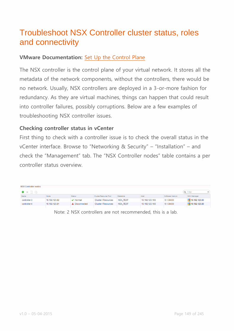
v1.0 – 05-04-2015 Page 149 of 245
Troubleshoot NSX Controller cluster status, roles and connectivity
VMware Documentation: Set Up the Control Plane
The NSX controller is the control plane of your virtual network. It stores all the
metadata of the network components, without the controllers, there would be
no network. Usually, NSX controllers are deployed in a 3-or-more fashion for
redundancy. As they are virtual machines, things can happen that could result
into controller failures, possibly corruptions. Below are a few examples of
troubleshooting NSX controller issues.
Checking controller status in vCenter
First thing to check with a controller issue is to check the overall status in the
vCenter interface. Browse to “Networking & Security” – “Installation” – and
check the “Management” tab. The “NSX Controller nodes” table contains a per
controller status overview.
Note: 2 NSX controllers are not recommended, this is a lab.
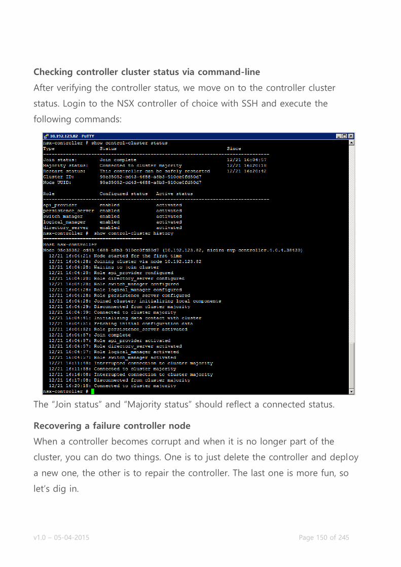
v1.0 – 05-04-2015 Page 150 of 245
Checking controller cluster status via command-line
After verifying the controller status, we move on to the controller cluster
status. Login to the NSX controller of choice with SSH and execute the
following commands:
The “Join status” and “Majority status” should reflect a connected status.
Recovering a failure controller node
When a controller becomes corrupt and when it is no longer part of the
cluster, you can do two things. One is to just delete the controller and deploy
a new one, the other is to repair the controller. The last one is more fun, so
let’s dig in.
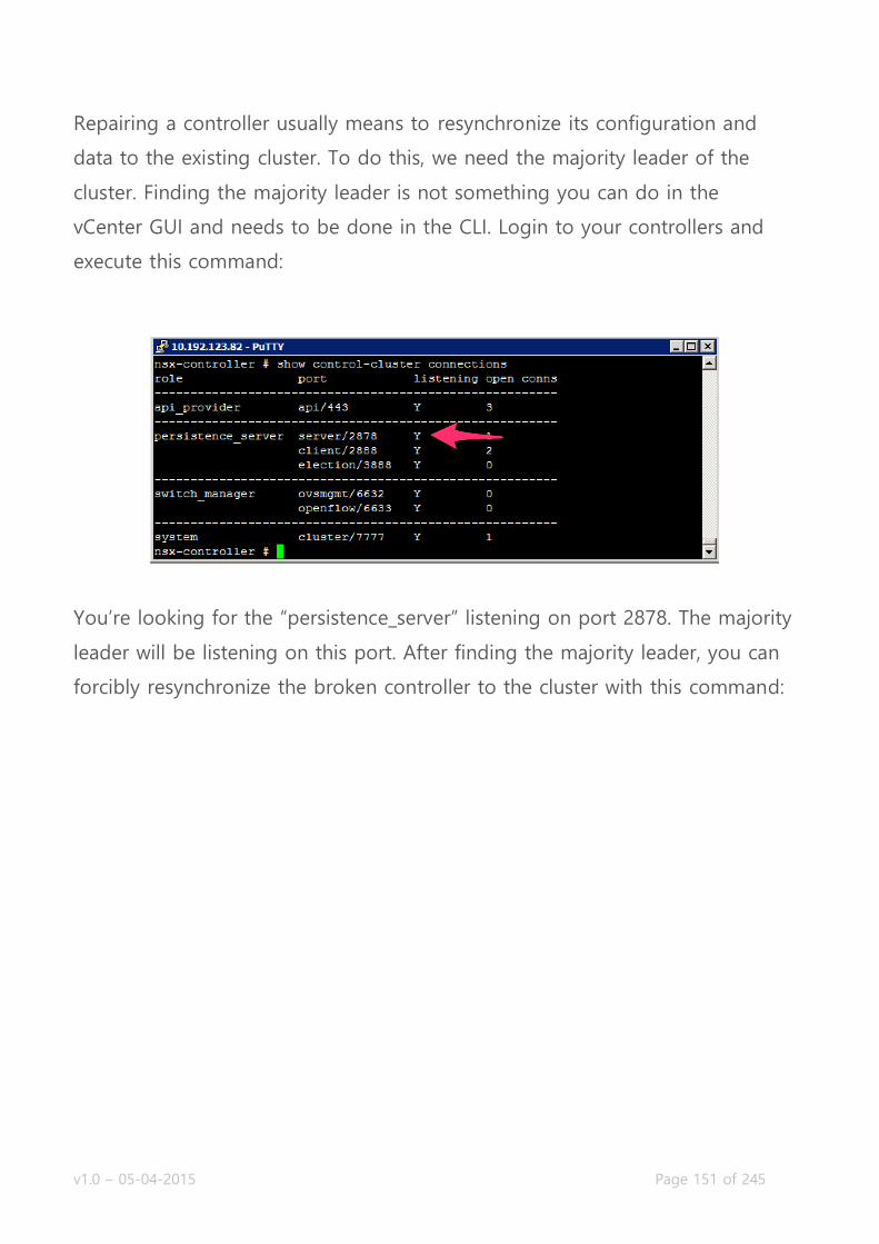
v1.0 – 05-04-2015 Page 151 of 245
Repairing a controller usually means to resynchronize its configuration and
data to the existing cluster. To do this, we need the majority leader of the
cluster. Finding the majority leader is not something you can do in the
vCenter GUI and needs to be done in the CLI. Login to your controllers and
execute this command:
You’re looking for the “persistence_server” listening on port 2878. The majority
leader will be listening on this port. After finding the majority leader, you can
forcibly resynchronize the broken controller to the cluster with this command:

v1.0 – 05-04-2015 Page 152 of 245
Troubleshoot active NSX Controller connections
With troubleshooting active NSX Controller connections, I’m assuming to
make them visible. Below are a few commands to get some insight into the
open connections of a controller.
show control-cluster connections (show active cluster connections)

v1.0 – 05-04-2015 Page 153 of 245
show control-cluster core stats (show cluster connections current, received,
transmitted)
show network connections of-type tcp (show active TCP connections)
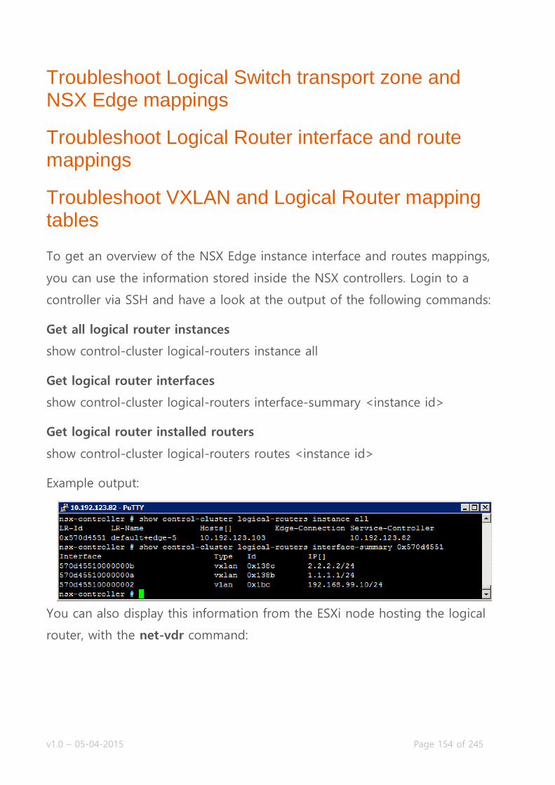
v1.0 – 05-04-2015 Page 154 of 245
Troubleshoot Logical Switch transport zone and NSX Edge mappings
Troubleshoot Logical Router interface and route mappings
Troubleshoot VXLAN and Logical Router mapping tables
To get an overview of the NSX Edge instance interface and routes mappings,
you can use the information stored inside the NSX controllers. Login to a
controller via SSH and have a look at the output of the following commands:
Get all logical router instances
show control-cluster logical-routers instance all
Get logical router interfaces
show control-cluster logical-routers interface-summary <instance id>
Get logical router installed routers
show control-cluster logical-routers routes <instance id>
Example output:
You can also display this information from the ESXi node hosting the logical
router, with the net-vdr command:

v1.0 – 05-04-2015 Page 155 of 245
Getting Transport Zone (VXLAN backend) information can help you
troubleshoot connectivity issues. Useful information is usually located on the
ESXi node.
# esxcli network vswitch dvs vmware vxlan network mac --vds-name <distributed vsw
itch> --vxlan-id <VXLAN id>
IP Segment ID Is MTEP 192.168.99.104 192.168.99.0 False
To get a lot more information, check this awesome post by William Lam.

v1.0 – 05-04-2015 Page 156 of 245
Troubleshoot L2 Bridge learned MAC addresses
The Logical Distributed Router can bridge VXLAN and VLANs. The control VM
of the LDR executes this bridging and learn the physical mac addresses. Login
to the ESXi node hosting the LDR Control VM, lookup the LDR name with a
previous mentioned command and execute the following commands to get an
overview of MAC addresses learned on the bridge.
First, let’s have a look at the general information about the bridge:

v1.0 – 05-04-2015 Page 157 of 245
After which we can look at the mac address table for the different networks
the bridge is attached to:
As you can see, the VXLAN network does not have any hosts on it, but the
VLAN network does have quite a few hosts on it.
Troubleshoot distributed and edge firewall implementations
The Distributed Firewall is inside the ESXi kernel, so the ESXi node knows
about what policies are configured on the virtual machines the ESXi node
hosts. You can learn about the policies set on a VM through the command
line of ESXi.
First, we need to find the UUID of the virtual machine called App01:
~ # summarize-dvfilter | grep App01
world 1764245 vmm0:App01 vcUuid:'50 03 e7 19 22 48 f7 64-41 9a c8 4b 6f 75 31 69'

v1.0 – 05-04-2015 Page 158 of 245
Then we look for the filter name for that virtual machine UUID:
~ # vsipioctl getfilters
Filter Name : nic-1764245-eth1-vmware-sfw.2
VM UUID : 50 03 e7 19 22 48 f7 64-41 9a c8 4b 6f 75 31 69
VNIC Index : 1
Service Profile : --NOT SET--
Filter Name : nic-1764245-eth0-vmware-sfw.2
VM UUID : 50 03 e7 19 22 48 f7 64-41 9a c8 4b 6f 75 31 69
VNIC Index : 0
Service Profile : --NOT SET--
As you might notice, this App01 virtual machine has two vNICs. That is why it
has two policies attached to it.
After getting the filter name, you can look up the rules for that filter:
~ # vsipioctl getrules -f
nic-1764245-eth0-vmware-sfw.2
ruleset domain-c7 {
# Filter rules
rule 1011 at 1 inout protocol any from addrset ip-securitygroup-15 to any drop;
rule 1006 at 2 inout protocol any from addrset ip-securitygroup-15 to any drop;
rule 1010 at 3 inout protocol tcp from addrset ip-securitygroup-12 to addrset ip-securitygroup-13 p
ort 5672 accept;
rule 1009 at 4 inout protocol tcp from addrset src1009 to addrset ip-securitygroup-14 port 3306 acc
ept;
rule 1008 at 5 inout protocol tcp from any to addrset ip-securitygroup-12 port 443 accept with log;
rule 1008 at 6 inout protocol tcp from any to addrset ip-securitygroup-12 port 80 accept with log;
rule 1008 at 7 inout protocol tcp from any to addrset ip-securitygroup-12 port 1234 accept with log
;
rule 1004 at 8 inout protocol ipv6-icmp icmptype 135 from any to any accept;
rule 1004 at 9 inout protocol ipv6-icmp icmptype 136 from any to any accept;
rule 1007 at 10 inout protocol any from any to any accept;
rule 1003 at 11 inout protocol udp from any to any port 67 accept;
rule 1003 at 12 inout protocol udp from any to any port 68 accept;
rule 1002 at 13 inout protocol any from any to any accept;
}
ruleset domain-c7_L2 {
# Filter rules
rule 1001 at 1 inout ethertype any from any to any accept;
}
~ #
You can also look up the address lists that these rules are using for traffic
policing:
~ # vsipioctl getaddrsets -f
nic-1764245-eth0-vmware-sfw.2
addrset ip-securitygroup-12 { }
addrset ip-securitygroup-13 { }
addrset ip-securitygroup-14 { }
addrset ip-securitygroup-15 { }
addrset src1009 { }
~ #

v1.0 – 05-04-2015 Page 159 of 245
Objective 5.3 – Troubleshoot Common Connectivity Issues
Troubleshoot virtual machine connectivity to Logical Switches
Troubleshoot dynamic routing protocols
Troubleshoot Virtual Private Networks (VPNs)
Troubleshoot VXLAN, VTEP, and VNI configuration and connectivity
Troubleshoot virtual machine connectivity to Logical Switches
I’m not really sure what VMware means with this subject. There are several
things that fall under this, like VXLAN connectivity preventing the virtual
machine from going across the logical switch. We’ll cover this in other topics.
Troubleshoot dynamic routing protocols
The NSX Edge can use OSPF, BGP and IS-IS for dynamic routing between
other network components (other Edges or physical devices). Below are some
troubleshooting tips for dynamic routing:
Show active neighbors
vShield-edge-12-0> show ip ospf neighbor
Neigbhor ID Priority Address Dead Time State
1.1.1.1 128 192.168.99.1 36 Full/DR
vShield-edge-2-0> show ip bgp neighbors
vShield-edge-2-0> show isis neighbors

v1.0 – 05-04-2015 Page 160 of 245
Show installed dynamic routes
vShield-edge-2-0> sh ip route bgp
vShield-edge-2-0> sh ip route isis
vShield-edge-12-0> show ip route ospf
Codes: O - OSPF derived, i - IS-IS derived, B - BGP derived, C - connected, S - static, L1 - IS-IS le
vel-1, L2 - IS-IS level-2, IA - OSPF inter area, E1 - OSPF external type 1, E2 - OSPF external type 2
, N1 - OSPF NSSA external type 1, N2 - OSPF NSSA external type 2
O E2 1.1.1.0/24 [110/0] via 192.168.99.1
O E2 2.2.2.0/24 [110/0] via 192.168.99.1
O E2 10.1.5.0/24 [110/0] via 192.168.99.1
O E2 192.168.1.0/24 [110/0] via 192.168.99.1
Show interfaces listening for neighbors
vShield-edge-2-0> show ip ospf interface
vNic_3 is activated
Internet Address 192.168.99.1, Network Mask 255.255.255.0, Area 0.0.0.0
Transmit Delay is 1 sec, Network Type BROADCAST, State DR, Priority 128
Designated Router's Interface Address 192.168.99.1
Backup Designated Router's Interface Address 0.0.0.0
Timer intervals configured, Hello 10, Dead 40, Retransmit 5
vShield-edge-2-0> show isis interface
Show link state database for OSPF/ISIS
vShield-edge-2-0> show isis database vShield-edge-2-0> show ip ospf database
Detect Authentication Failure
vShield-edge-12-0> show log reverse
2015-01-31T12:38:18+00:00 vShield-edge-12-0 routing[876]: [user.info] AUDIT 0x3e02-39 (0000): OSPF 1
Packet received with unexpected authentication type 1.
Detect OSPF Area Misconfiguration
vShield-edge-12-0> show log reverse
2015-01-31T12:40:58+00:00 vShield-edge-12-0 routing[876]: [user.emerg] EXCEPTION 0x3e01-110 (0000): O
SPF 1 OSPF packet dropped because it was received on non-existent or inactive virtual or sham link
Debugging
In addition to doing all kinds of show commands to determine the status of
ISIS, OSPF or BGP, you can also debug the protocols to get a lot more
information about what the processes are doing in the background. To start
the debugging process:
vShield-edge-12-0> debug ip ospf
vShield-edge-12-0> debug ip bgp
vShield-edge-12-0> debug isis

v1.0 – 05-04-2015 Page 161 of 245
When enabled, the log will fill up with messages from the protocol. You
should never let this running continuously; always disable it when you’re done.
To stop the debugging process:
vShield-edge-12-0> no debug ip ospf
vShield-edge-12-0> no debug ip bgp
vShield-edge-12-0> no debug isis
A sample output of the debug messages OSPF sends when establishing a
neighbor relationship:
2015-01-31T12:46:58+00:00 vShield-edge-12-0 routing[876]: [user.info] AUDIT 0x3e01-226 (0000): OSPF 1
i/f idx 0X00000004 rtr ID 1.1.1.1 IP addr 192.168.99.1 neighbor FSM has processed an input.
2015-01-31T12:46:58+00:00 vShield-edge-12-0 routing[876]: [user.info] AUDIT 0x3e01-200 (0000): OSPF 1
Database exchange with an adjacent OSPF neighbor has been completed.
2015-01-31T12:46:58+00:00 vShield-edge-12-0 routing[876]: [user.info] AUDIT 0x3e01-226 (0000): OSPF 1
i/f idx 0X00000004 rtr ID 1.1.1.1 IP addr 192.168.99.1 neighbor FSM has processed an input.
Troubleshoot Virtual Private Networks (VPNs)
VPNs can be tricky, especially between two vendors. So when you’re
configuring them, you should know where to look if one doesn’t come up.
The NSX Edge keeps logs of the events, which are stored in
/var/log/messages. The contents can be viewed through the command “show
log”. You can either check that or check the central syslog facility, if you have
one. The following log lines are taken from the output of “show log reverse”.
Phase 1 or 2 Policy Mismatch
When the VPN on the NSX Edge hangs in the “STATE_MAIN_I1″ state, there’s
something wrong with the Phase 1 or 2 negotiations. Look for “s1-c1″ and
“NO_PROPOSAL_CHOSEN” in the logs:
Jan 31 13:11:35 gw-vpn01 ipsec[6769]: | got payload 0x800(ISAKMP_NEXT_N) needed: 0x0 opt: 0x0
Jan 31 13:11:35 gw-vpn01 ipsec[6769]: | ***parse ISAKMP Notification Payload:
Jan 31 13:11:35 gw-vpn01 ipsec[6769]: | next payload type: ISAKMP_NEXT_NONE
Jan 31 13:11:35 gw-vpn01 ipsec[6769]: | length: 96
Jan 31 13:11:35 gw-vpn01 ipsec[6769]: | DOI: ISAKMP_DOI_IPSEC
Jan 31 13:11:35 gw-vpn01 ipsec[6769]: | protocol ID: 0
Jan 31 13:11:35 gw-vpn01 ipsec[6769]: | SPI size: 0
Jan 31 13:11:35 gw-vpn01 ipsec[6769]: | Notify Message Type: NO_PROPOSAL_CHOSEN

v1.0 – 05-04-2015 Page 162 of 245
Jan 31 13:11:35 gw-vpn01 ipsec[6769]: "s1-c1" #1: ignoring informational payload, type NO_PROPOSAL_CH
OSEN msgid=00000000
Pre-Shared Key Mismatch
When the PSK does not match, the log will tell you something about
“INVALID_ID_INFORMATION”, after initiating the “Quick Mode” for information
exchange.
Jan 31 13:15:00 gw-vpn01 ipsec[3855]: "s1-c1" #1: transition from state STATE_MAIN_I3 to state STATE_
MAIN_I4
Jan 31 13:15:00 gw-vpn01 ipsec[3855]: "s1-c1" #1: STATE_MAIN_I4: ISAKMP SA established {auth=OAKLEY_P
RESHARED_KEY cipher=oakley_3des_cbc_192 prf=oakley_sha group=modp1024}
Jan 31 13:15:00 gw-vpn01 ipsec[3855]: "s1-c1" #1: Dead Peer Detection (RFC 3706): enabled
Jan 31 13:15:00 gw-vpn01 ipsec[3855]: "s1-c1" #2: initiating Quick Mode PSK+ENCRYPT+TUNNEL+PFS+UP+SAR
EFTRACK {using isakmp#1 msgid:e8add10e proposal=3DES(3)_192-SHA1(2)_160 pfsgroup=OAKLEY_GROUP_MODP102
4}
Jan 31 13:15:00 gw-vpn01 ipsec[3855]: "s1-c1" #1: ignoring informational payload, type INVALID_ID_INF
ORMATION msgid=00000000
Troubleshoot VXLAN, VTEP, and VNI configuration and connectivity
MTU Size
VXLAN requires you to set a larger MTU size. The recommended size is 1600.
You can check from the ESXi server CLI whether the VXLAN stack has issues
and if the correct MTU has been configured on the ESXi host uplinks by
simply doing a (special) ping:
~ # ping ++netstack=vxlan -d -s 1572 -I vmk3 192.168.99.103
PING 192.168.99.103 (192.168.99.103): 1572 data bytes
1580 bytes from 192.168.99.103: icmp_seq=0 ttl=64 time=1.108 ms
1580 bytes from 192.168.99.103: icmp_seq=1 ttl=64 time=3.246 ms
If the ESXi host (192.168.99.103 is a different host from where the test was)
does not respond correctly, try with a lower packet size like 1472. If it does
respond that time, the MTU is not configured correctly.
If it does respond, but VXLAN issues persist, zoom in on the controller and
ESXi host communication. First, get the ID of the logical switch you’re having

v1.0 – 05-04-2015 Page 163 of 245
issues with (through the GUI or CLI) and login to a controller to see whether
your ESXi hosts are logged in to the controller for this logical switch:
nsx-controller # show control-cluster logical-switches connection-table
5003 Host-IP Port ID 192.168.99.103 43261 1 192.168.99.104 42155 2
If that looks okay, check whether the ESXi hosts have registered as VTEPs with
the controller:
nsx-controller # show control-cluster logical-switches vtep-table 5003
VNI IP Segment MAC Connection-ID
5003 192.168.99.103 192.168.99.0 00:50:56:63:18:db 1
5003 192.168.99.104 192.168.99.0 00:50:56:66:08:fe 2
If there are no VTEPs registered, there might be an issue with multicast on the
network (if configured). If you’ve discovered that the ESXi hosts have
registered as VTEPs, check whether any MAC addresses of virtual machines are
registering with the controller for the logical switch:
nsx-controller # show control-cluster logical-switches mac-table 5003
VNI MAC VTEP-IP Connection-ID
5003 00:50:56:bc:21:ab 192.168.99.103 1
5003 00:50:56:ed:1a:bc 192.168.99.104 2
If there are no MAC addresses present, multicast (if configured) might be the
culprit. If everything looks fine and you still don’t have connectivity, start
checking firewalls.

v1.0 – 05-04-2015 Page 164 of 245
Objective 5.4 – Troubleshoot Common Service Issues
Troubleshoot NSX Management Services issues
Troubleshoot Service creation/deletion issues
Troubleshoot Service Group creation/deletion issues
Troubleshoot DHCP service issues
Troubleshoot DNS service issues
Troubleshoot Network Address Translation (NAT) service issues
Troubleshoot Logical Load Balancer implementation issues

v1.0 – 05-04-2015 Page 165 of 245
Troubleshoot NSX Management Services issues
If you’re having trouble with provisioning NSX services, it’d be wise to check
the NSX Manager and its services. Login to your NSX Manager to check the
status page:
The vPostgres service is the database service. Without this, none of the
configuration will be saved or even read. The API would give errors when
retrieving or setting configuration, the control-plane would be generally
unusable. The data-plane would be unaffected. The RabbitMQ service is an
internal messaging service. The NSX Manager uses this to execute tasks,
basically respond to certain UI interactions. If the RabbitMQ service is down,
the most configuration will not be executed, even though it appears to be
successful.
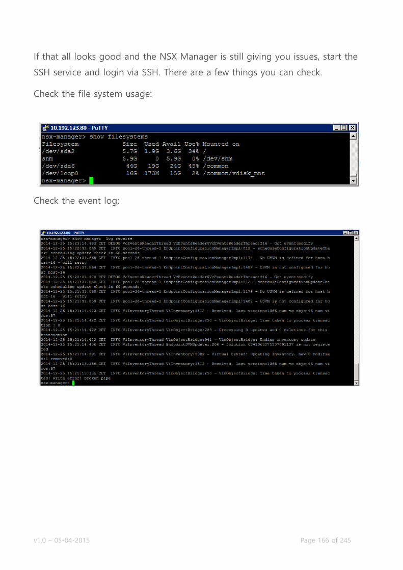
v1.0 – 05-04-2015 Page 166 of 245
If that all looks good and the NSX Manager is still giving you issues, start the
SSH service and login via SSH. There are a few things you can check.
Check the file system usage:
Check the event log:
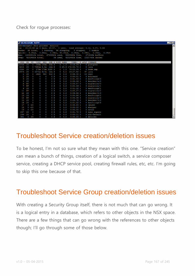
v1.0 – 05-04-2015 Page 167 of 245
Check for rogue processes:
Troubleshoot Service creation/deletion issues
To be honest, I’m not so sure what they mean with this one. “Service creation”
can mean a bunch of things, creation of a logical switch, a service composer
service, creating a DHCP service pool, creating firewall rules, etc, etc. I’m going
to skip this one because of that.
Troubleshoot Service Group creation/deletion issues
With creating a Security Group itself, there is not much that can go wrong. It
is a logical entry in a database, which refers to other objects in the NSX space.
There are a few things that can go wrong with the references to other objects
though; I’ll go through some of those below.

v1.0 – 05-04-2015 Page 168 of 245
Introspection Services unavailable
Selected services (Guest Introspection or Network Introspection) are not
usable on the cluster which the virtual machines that are selected. When
linking Security Policies to security groups, services can be put in the path of
the network. You can even select services that are ultimately unavailable on
the vSphere clusters:
Virtual Machines not showing up
There are three ways to include virtual machines in a Security Group: dynamic
membership (based on machine criteria), static including and static excluding.
Reasons for virtual machines not showing up in a security group are fairly
simple: they do not match are of the dynamic membership criteria or they are
statically excluded from the selection.
The dynamic membership can contain a lot of variable rules, which can
complement or contradict each other in the same set of rules. Make sure you
don’t make it overly complicated; keep it simple where ever you can.
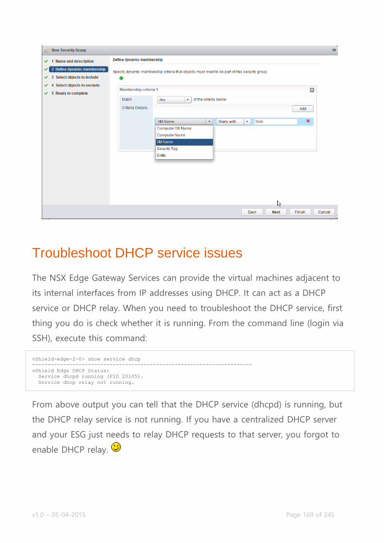
v1.0 – 05-04-2015 Page 169 of 245
Troubleshoot DHCP service issues
The NSX Edge Gateway Services can provide the virtual machines adjacent to
its internal interfaces from IP addresses using DHCP. It can act as a DHCP
service or DHCP relay. When you need to troubleshoot the DHCP service, first
thing you do is check whether it is running. From the command line (login via
SSH), execute this command:
vShield-edge-2-0> show service dhcp
-----------------------------------------------------------------------
vShield Edge DHCP Status:
Service dhcpd running (PID 20105).
Service dhcp relay not running.
From above output you can tell that the DHCP service (dhcpd) is running, but
the DHCP relay service is not running. If you have a centralized DHCP server
and your ESG just needs to relay DHCP requests to that server, you forgot to
enable DHCP relay.

v1.0 – 05-04-2015 Page 170 of 245
Moving on to the DHCP server service, specifically showing and clearing DHCP
leases for virtual machines. To get an overview of all leases given out to virtual
machines, execute this:
vShield-edge-2-0> show service dhcp leaseinfo
# The format of this file is documented in the dhcpd.leases(5) manual page.
# This lease file was written by isc-dhcp-4.2.5-P1
server-duid "\000\001\000\001\034M\026\326\000PV\203\355\374";
lease 192.168.1.200 {
starts 6 2015/01/17 12:51:20;
ends 0 2015/01/18 12:51:20;
cltt 6 2015/01/17 12:51:20;
binding state active;
next binding state free;
rewind binding state free;
hardware ethernet 00:50:56:83:b3:df;
}
vShield-edge-2-0>
The output will be formatted in a pretty readable format. You’ve got a block
of settings per lease that is given out. Starting with the IP address, you can
also view the time the lease was given out, when it will be released and the
mac address it is bound to.
You can manually release DHCP leases from the command line. I have not
found a way to do so in the GUI, this seems the only way:
vShield-edge-2-0> enable
Password:
vShield-edge-2-0# clear service dhcp lease
vShield-edge-2-0# disable
vShield-edge-2-0> show service dhcp leaseinfo
# The format of this file is documented in the dhcpd.leases(5) manual page.
# This lease file was written by isc-dhcp-4.2.5-P1
server-duid "\000\001\000\001\034M\031\231\000PV\203\355\374";
vShield-edge-2-0>
The not so funny bit about this command is that you cannot choose which
lease you want to clear. It is all or nothing, which can be a problem if you
have a few VMs with DHCP and you’d like to keep those on the same IP
address. Having said that, you should really enter manual DHCP bindings if
that is a concern.
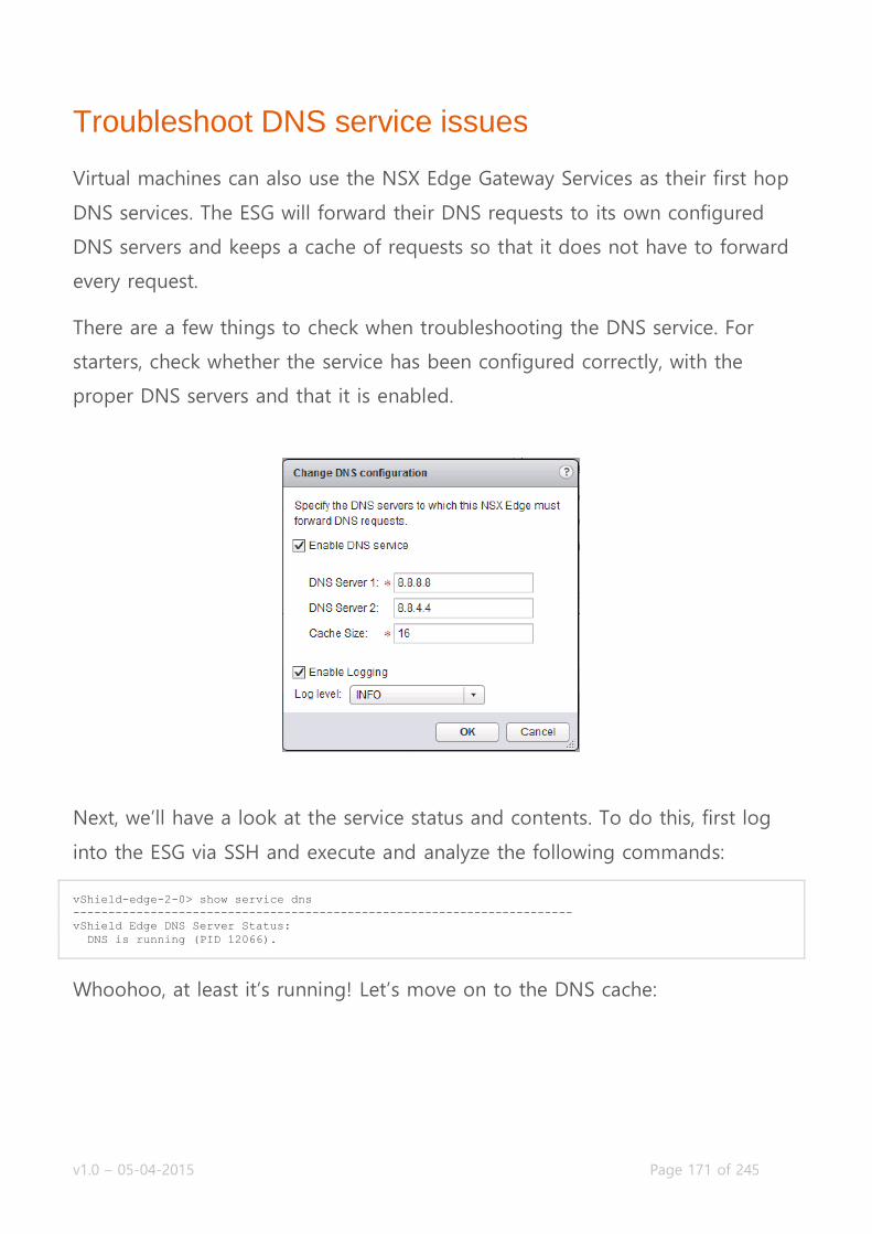
v1.0 – 05-04-2015 Page 171 of 245
Troubleshoot DNS service issues
Virtual machines can also use the NSX Edge Gateway Services as their first hop
DNS services. The ESG will forward their DNS requests to its own configured
DNS servers and keeps a cache of requests so that it does not have to forward
every request.
There are a few things to check when troubleshooting the DNS service. For
starters, check whether the service has been configured correctly, with the
proper DNS servers and that it is enabled.
Next, we’ll have a look at the service status and contents. To do this, first log
into the ESG via SSH and execute and analyze the following commands:
vShield-edge-2-0> show service dns
-----------------------------------------------------------------------
vShield Edge DNS Server Status:
DNS is running (PID 12066).
Whoohoo, at least it’s running! Let’s move on to the DNS cache:

v1.0 – 05-04-2015 Page 172 of 245
vShield-edge-2-0> show service dns cache
;
; Start view vsm-default-view
;
;
; Cache dump of view 'vsm-default-view' (cache vsm-default-view)
; $DATE 20150117123540 ...snip...
; answer 113.66.194.173.in-addr.arpa. 3382 PTR we-in-f113.1e100.net.
; answer 138.66.194.173.in-addr.arpa. 4455 PTR we-in-f138.1e100.net.
; answer google.nl. 219 A 74.125.133.94 ...snip...
The cache contains a lot information, I’ve snipped it down a bit. The important
things to notice is the “$DATE” value, which is the time the DNS record was
cached and will be cleared.
If you’re having issues with the ESG returning wrong DNS records, you can
clear the DNS cache manually by doing:
vShield-edge-2-0> enable
Password: *********
vShield-edge-2-0# clear service dns cache
vShield-edge-2-0# disable
vShield-edge-2-0> show service dns cache
;
; Start view vsm-default-view
;
;
; Cache dump of view 'vsm-default-view' (cache vsm-default-view)
; $DATE 20150117124458
;
; Address database dump
;
;
; Unassociated entries
;
;
; Bad cache
;
;
vShield-edge-2-0>

v1.0 – 05-04-2015 Page 173 of 245
Troubleshoot Network Address Translation (NAT) service issues
The first gold rule of troubleshooting NAT issues, is checking whether the
firewall service is enabled. The NAT rules are injected to the firewall rules, as
they are on a Linux server. The ESG is a linux-type appliance, which works with
the same firewall format as IPTables. If you’re used to CentOS, Redhat kind of
Linux distros, the following troubleshooting command outputs will look very
familiar to you. If you’re not one of those people, it’ll take some getting used
to.
All right, with that out of the way, let’s dig in. To get an active overview of all
NAT rules, you can execute the following command via command line:
vShield-edge-2-0> show nat
Chain PREROUTING (policy ACCEPT 0 packets, 0 bytes)
rid pkts bytes target prot opt in out source destination
0 0 0 int_dnat all -- * * 0.0.0.0/0 0.0.0.0/0
0 0 0 usr_dnat all -- * * 0.0.0.0/0 0.0.0.0/0
Chain INPUT (policy ACCEPT 0 packets, 0 bytes)
rid pkts bytes target prot opt in out source destination
Chain OUTPUT (policy ACCEPT 0 packets, 0 bytes)
rid pkts bytes target prot opt in out source destination
Chain POSTROUTING (policy ACCEPT 0 packets, 0 bytes)
rid pkts bytes target prot opt in out source destination
0 0 0 int_snat all -- * * 0.0.0.0/0 0.0.0.0/0
0 0 0 usr_snat all -- * * 0.0.0.0/0 0.0.0.0/0
Chain int_dnat (1 references)
rid pkts bytes target prot opt in out source destination
Chain int_snat (1 references)
rid pkts bytes target prot opt in out source destination
0 0 0 ACCEPT all -- * * 0.0.0.0/0 0.0.0.0/0 policy match dir out pol ips
ec mode tunnel
Chain usr_dnat (1 references)
rid pkts bytes target prot opt in out source destination
0 234 1423 LOG tcp -- vNic_0 * 0.0.0.0/0 10.192.123.88 multiport dports 1234
LOG flags 0 level 4 prefix "DNAT_"
0 234 1423 DNAT tcp -- vNic_0 * 0.0.0.0/0 10.192.123.88 multiport
dports 1234 to:192.168.1.200:1233
Chain usr_snat (1 references)
rid pkts bytes target prot opt in out source destination
0 2 84 LOG all -- * vNic_0 192.168.1.0/24 0.0.0.0/0 LOG flags 0 level 4 pre
fix "SNAT_"
0 2 84 SNAT all -- * vNic_0 192.168.1.0/24 0.0.0.0/0 to:10.192.123.88
Now, this is an ESG with two NAT rules configured. A single source NAT and a
single destination NAT rule. You’ll notice that those rules are placed under the
‘usr_dnat’ and ‘usr_snat’ chains. All NAT rules you configure yourself will be
placed under those chains, all NAT rules that are configured by the ESG itself

v1.0 – 05-04-2015 Page 174 of 245
(when you are configuring other services and the ESG needs NAT rules to
activate those) will be placed under the ‘int_dnat’ and ‘int_snat’ chains. All
rules are on a first-come first-serve basis, so rules actually doing something
(not the LOG rules) are processed from the top down.
Let’s break it down a bit and focus on this one:
Chain usr_snat (1 references)
rid pkts bytes target prot opt in out source destination
0 2 84 LOG all -- * vNic_0 192.168.1.0/24 0.0.0.0/0 LOG flags 0 level 4 prefi
x "SNAT_"
0 2 84 SNAT all -- * vNic_0 192.168.1.0/24 0.0.0.0/0 to:10.192.123.88
The “rid” field is a simple rule id, which is an internal ID as far as I can tell. The
“pkts” and “bytes” fields are packet amount and size counters, you can see
quickly spot whether the rule is getting any traffic. The “prot” field is the
network protocol type (tcp, udp, ip, etc). The “out” field is the outgoing
interface on which this rule is applied; this needs to be the interface that the
traffic is leaving (or entering in destination NAT). The “source” and
“destination” fields are the matching IP ranges on which the rule is triggered.
The last field is extra information on what the rule does. As you can see, the
first rule only creates a log entry with a level 4 notification and prefixes the
log entry with SNAT_. The second rule shows the IP address the source range
is translated to. This can be the external interface IP address or a secondary IP
address on the interface.
The destination NAT rules have pretty much the same fields and syntax, except
for the extra information in the last field:
multiport dports 1234 LOG flags 0 level 4 prefix "DNAT_" multiport dports 1234 to:192.168.1.200:1233
Destination NAT works in most cases as a port forwarding mechanism. The
configuration used for a port forward is mentioned in the rules output. Of the
output above, the first rule is another simple logging rule, logging to syslog

v1.0 – 05-04-2015 Page 175 of 245
with a level 4 and the message prefixed with DNAT_. The second rule contains
the port mapping information. The first bit, multiport basically just means it
can contain multiple destination ports. The second part “dports 1234″ contains
the actual destination (outside) ports and behind that is the translated inside
IP address and port. When reading this right, you’ll see a translation of
incoming port 1234 on vNic_0 that is translated to 192.168.1.200 to port 1233.
Troubleshoot Logical Load Balancer implementation issues
Below is an overview of commands you can use to troubleshoot load balancer
issues. Seeing as load balancing is a broad subject, there is a lot of
information you can grab from the Edge Services Gateway. I recommend using
the command line for faster access to data and the fact that you can jump a
bit more in detail.
vShield-edge-2-0> show service loadbalancer ?
error Show loadbalancer Latest Errors information.
monitor Show loadbalancer HealthMonitor information.
pool Show loadbalancer pool information.
session Show loadbalancer Session information.
table Show loadbalancer Sticky-Table information.
virtual Show loadbalancer virtualserver information.
show service loadbalancer error
Show loadbalancer Latest Errors information.
Show the latest errors that occurred on the load balancer service.
Configuration errors, health check errors, session errors, name it. If you’re
having a misbehaving load balancer, check this first.
show service loadbalancer monitor
Checks the load balancer health monitor status. See if every service that is
configured is healthy or is partly down.
v1.0 – 05-04-2015 Page 176 of 245
show service loadbalancer pool
Retrieves load balancer pool information.
show service loadbalancer session
Shows all active network sessions to the configured load balancer services.
Handy to tell if any services are overloaded, or if they are even receiving traffic
at all.
show service loadbalancer table
Shows the current sticky connection table. If services are configured with a
sticky setting on them, recurring connections from the same origin will be
redirected to the same server. This table lists the mappings between
connections and servers.
show service loadbalancer virtual
The virtual server is where the connections come in. This will show the
configured virtual servers and current active information about those virtual
servers.

v1.0 – 05-04-2015 Page 177 of 245
Objective 6.1 – Configure and Administer Firewall Services
Create/Modify/Delete an Edge Firewall rule
Create/Modify/Delete a Distributed Firewall rule
Configure Source/Destination/Service/Action rule components
Modify the order/priority of Firewall rules
Create/Modify/Delete Firewall rule sections
Create/Modify/Delete Source and Destination Network Address
Translation rules
Create/Modify/Delete SpoofGuard policies
NSX Firewalls
There are several security measures inside the NSX platform. When it comes to
firewalls, you have two options; the Edge Services Gateway Firewall or the
Distributed Firewall.
The first one can act like any border gateway with a firewall, allowing and
blocking network traffic that goes through the border of a network (or logical
switch). The Distributed Firewall is another beast and is what makes NSX
unique in the security aspect of virtual machines. The Distributed Firewall is
similar to the Distributed Router, as firewall policies can be centrally managed
and are then pushed down to the ESXi hosts. The ESXi hosts use these firewall
rules inside the ESXi kernel to check the network traffic on a per virtual NIC
basis. This means that you can isolate virtual machines (to the vNIC level) from
their peer VMs in the same subnet, which usually is unfiltered communication
on any other platform. They usually call this micro segmentation.
NSX also makes creating the firewall policies a lot easier than other products
as you can use vSphere objects to select sources and destinations. Examples
v1.0 – 05-04-2015 Page 178 of 245
are a Cluster, Datacenter, Distributed Port Group, IP Sets, Legacy
(standard) Port Group, Logical Switch, Resource Pool, NSX Security Group,
vApp, Virtual Machine or vNIC.
If you mix it up, it means that you can create a firewall policy where you allow
vNIC-0 from VM-A to only communicate with a specific Resource Pool, where
membership of that resource pool can be dynamic; add another VM and that
VM will be allowed as well.
Another important feature which you should be diving in to, are the Security
Groups. Security Groups dynamically filled groups of virtual machines. As
mentioned before, you can use security groups in firewall policies. Combine
that with Security Group Membership criteria and the sky is the limit. Inside
the Membership criteria, you can choose what goes in the security group.
Criteria objects can be: Computer OS Name, Computer Name, VM Name,
Security Tag and (vSphere) Entity. These objects can be matched in several
ways, you can enter text that the object should contain (“Contains”), what the
object should end with (“Ends with”), or the object should completely equal
(“Equals”), or the object should not equal to (“Not Equals To”), or what it
should start with (“Starts With”).
Using these criteria, you for example can build groups where you can simply
tag a specific virtual machine with the tag “webserver” and that virtual
machine will get all the required firewall policies to actually act as a web
server (connect to the database server, have users connect to port 80, etc, etc).
I have to mention that the functionality for a security group does not stop
with the firewall policies; they are also used inside the Service Composer to
link third party vendor services (F5, Palo Alto, etc) to the virtual machines
inside these groups. For instance, you can force certain virtual machines
through the Palo Alto advanced firewall services for deeper protection of
those VMs. More on that in the Service Composer chapter.

v1.0 – 05-04-2015 Page 179 of 245
I hope you can see how powerful these security groups are now, and I really
should emphasis that you have to go and play with them to understand just
how powerful they are. But for now, let’s dive into the tasks for this objective.
Create/Modify/Delete an Edge Firewall rule
Requirements:
NSX Environment, including a NSX Edge.
VMware Documentation: Working with Edge Firewall Rules
The Edge Services Gateway firewall is the border firewall of your local network
(Logical Switch to Logical Switch or the physical network), treat the firewall
policies like any other border firewall.
Add a Firewall Policy to an ESG
Login to your vSphere Web Client.
Navigate to “Networking & Security” and select the “NSX Edges” menu.
Choose the NSX Edge you want to modify and select the “Manage” tab.
Then select the “Firewall” sub-tab and first check if the firewall is
enabled. If it’s disabled, click the “Enable” button and “Publish Changes”
when it appears to enable the firewall. Do this only with new ESGs or
when you’re sure the firewall policies are correct (or if there’s a “Default
Rule” that allows any), to prevent cutting off network communication.
To start adding a policy, click the “+” icon at the top of the policy table.
You can also click the “+” icon at the rule number to get a menu where
you can select to create a rule below or above another one.
This adds a row in the policy table and you need to edit the policy
inside the table. This is a bit unnatural to the rest of NSX (wizard based),
but you’ll get used to it.
v1.0 – 05-04-2015 Page 180 of 245
To edit a policy, click the “+” icon in the column you’re hovering your
mouse over.
Give the policy a name you recognize (such as “Allow HTTP”), then select
the source object (remember the vSphere objects you can use here?) or
leave it as any, select a destination object or leave it as any, then select
the service (the predefined services cover a lot, but you can also create
your own service inside the Service popup, if needed) and finally, select
the Action that should be taken. On Action you can select Deny, Accept
or Reject, opt to log the policy hits and under “Advanced options” you
can select the traffic direction this policy should be applied on.
You can also base the policy on IP (single, subnet or range), instead of
an object. Click the “IP” icon in the source or destination column to do
so.
For the service, you can also use a protocol or source port. Click the
“Port” icon in the service column to do so.
Repeat this process for any other policies you would like to add. When
you’re done, click “Publish Changes” at the top of the page to push the
policies down to the ESG.
In the example below, I created a policy called “Allow HTTP” which allows
traffic from anywhere to the “Web-SG” Security Group (housing VMs starting
with “Web”) over HTTP and HTTPS.

v1.0 – 05-04-2015 Page 181 of 245
Create/Modify/Delete a Distributed Firewall rule
Requirements:
NSX Environment with prepared ESXi hosts
VMware Documentation: Working with Firewall Rules
Distributed Firewall policies are the policies that get pushed down to the ESXi
hosts, so that they can police network traffic inside the kernel before it even
enters the virtual switch. Before expecting the Distributed Firewall to work,
make sure that your ESXi clusters are prepared and have the firewall enabled
(check “Networking & Security” – “Installation” – “Host Preparation” –
“Firewall” column, this should be “Enabled”). We are going to create
distributed firewall policies in the next bit.
Adding a Distributed Firewall policy works pretty much the same as adding a
firewall policy to the ESG. You add a policy, select the source, destination,
service and action and publish it. There are a few extra options though, such

v1.0 – 05-04-2015 Page 182 of 245
as Sections to group policies together (we’ll go into those later on), Layer-2
policies (instead of just Layer-3) and management over the Service Composer
policies (separate sections).
Add a Distributed Firewall policy
Login to your vSphere Web Client.
Navigate to “Networking & Security” and select the “Firewall” menu,
then the “Configuration” tab.
Click the “+” icon on a specific section or at the top of the table to add
a policy.
In the new policy, hover over the columns to click the “+” icon in there.
Select a source, destination, service and action for this policy.
Click “Publish Changes” when you’re done.
In the example below, I have added the same policy as we did in the previous
task on the ESG.
v1.0 – 05-04-2015 Page 183 of 245
Configure Source/Destination/Service/Action rule components
I’m not entirely sure what they mean here, but I’m pretty sure they mean that
you should be able to create or select custom destinations, sources and
services for use in the firewall policies.
The custom source and destinations that you can create are the Security
Groups, which will be covered later on. When it comes to selecting sources
and destinations, well, you did that in the previous sections.
That leaves custom services. Services can be added in two different places.
You can do it from the NSX Managers grouping objects or directly from the
service window. The added value of doing it through the NSX Manager is that
you can use the custom service on every firewall service (ESG and DFW).
Add a custom service from the Distributed Firewall
Login to your vSphere Web Client.
Navigate to “Networking & Security” and select the “Firewall” menu,
then the “Configuration” tab.
Hover over the policy you want to create the service for and click the
“+” icon in the Service column.
In the popup window, click the “New Service…” link to create a custom
service.
In the “Add Service” window, give the new service a name, select the
protocol (TCP, UDP, ICMP, etc) and enter the Destination ports when
required. Click “OK” when you’re done.
Your new service will automatically be selected in the “Selected Objects”
table. Click “OK” to confirm. Click “Publish Changes” when it appears to
take the policies into effect.
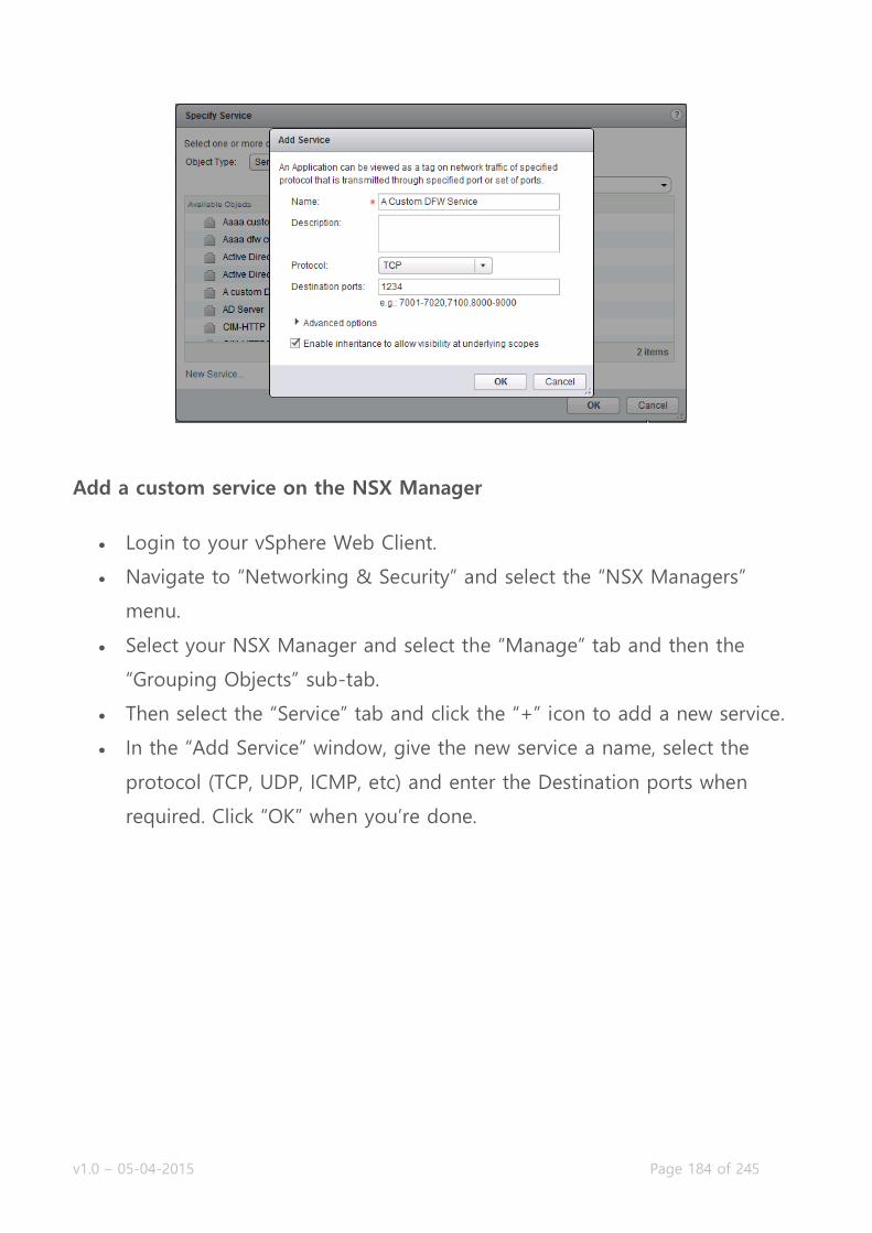
v1.0 – 05-04-2015 Page 184 of 245
Add a custom service on the NSX Manager
Login to your vSphere Web Client.
Navigate to “Networking & Security” and select the “NSX Managers”
menu.
Select your NSX Manager and select the “Manage” tab and then the
“Grouping Objects” sub-tab.
Then select the “Service” tab and click the “+” icon to add a new service.
In the “Add Service” window, give the new service a name, select the
protocol (TCP, UDP, ICMP, etc) and enter the Destination ports when
required. Click “OK” when you’re done.

v1.0 – 05-04-2015 Page 185 of 245
Modify the order/priority of Firewall rules
Requirements:
NSX Environment.
Existing firewall rules to re-order.
VMware Documentation: Change the Order of a Rule
As any existing firewall solution, NSX processes the firewall policies in a first-
come first-serve basis. Meaning if you have a “deny all” policy at the top and
an “allow service” underneath the deny policy, all your traffic will get denied.
To fix that, you’ll need to put the “deny all” policy at the bottom. Here’s how:
Re-ordering a Distributed Firewall rule
Login to your vSphere Web Client.
Navigate to “Networking & Security” and select the “Firewall” menu.

v1.0 – 05-04-2015 Page 186 of 245
Select the rule you want to move and click the “Move rule down” or
“Move rule up” icons:
Click “Publish Changes” to activate your changes.
Create/Modify/Delete Firewall rule sections
Requirements:
NSX Environment.
VMware Documentation: Working with Distributed Firewall Rule Sections
Inside the Distributed Firewall, you have the ability to create Sections, which
allow you to group certain firewall policies together to keep them organized.
They also help to keep overview in the configuration view, as the policies
inside the distributed firewall are for your entire virtual environment. With this,
I mean that the amount of policies that are configured in a real environment
could be humongous.
Adding a Section to the Distributed Firewall
Login to your vSphere Web Client.
Navigate to “Networking & Security” and select the “Firewall” menu.
To add a Section, click the folder icon with a “+” attached . Do this on
the existing section you want the new section to be near to (remember
the first-come first-serve rule).
In the popup window, give the new section a name and select whether
to place it above or below the section you used to create this new one.
Keep in mind that sections cannot be re-ordered in NSX 6.0.x.
Click “OK” to create the section and “Publish Changes” to activate.

v1.0 – 05-04-2015 Page 187 of 245
Create/Modify/Delete Source and Destination Network Address Translation rules
Requirements:
NSX Environment, including a deployed NSX Edge.
VMware Documentation: Managing NAT Rules
If you’ve reached this point, you should already know (and use) what NAT is,
but just to be complete: Network Address Translation (NAT) rules are a way to
make your border firewall to hide internal subnets from the outside world. For
example, every consumer internet connection will have an internal network
(your computers, phones, tablets, etc) which is in the globally determined
internal IP subnet range. Your border device will hide that internal network to
prevent overlap, create a security border between the outside and inside and
simply because the internal ranges are not routed on the internet. NAT is also
used in server environments where different server pods use the same internal
IP subnets, for instance in a development and Q&A environment where the
developers have individual pods but using the same internal IP subnets in
each pod. To read more about NAT, check this wiki article.
Important to know is that to use NAT on a NSX Edge, you need to have the
firewall service enabled. If you do not enable the firewall service, NAT will not
work.
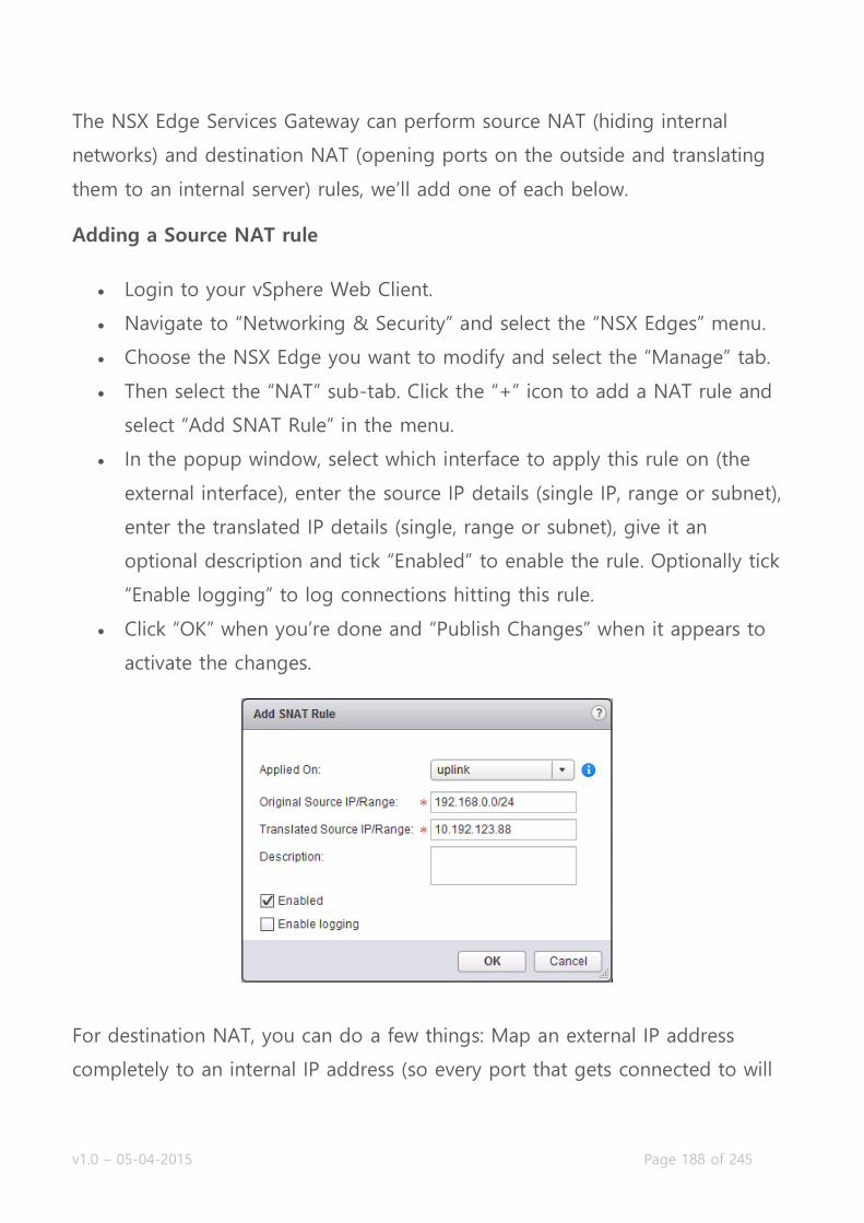
v1.0 – 05-04-2015 Page 188 of 245
The NSX Edge Services Gateway can perform source NAT (hiding internal
networks) and destination NAT (opening ports on the outside and translating
them to an internal server) rules, we’ll add one of each below.
Adding a Source NAT rule
Login to your vSphere Web Client.
Navigate to “Networking & Security” and select the “NSX Edges” menu.
Choose the NSX Edge you want to modify and select the “Manage” tab.
Then select the “NAT” sub-tab. Click the “+” icon to add a NAT rule and
select “Add SNAT Rule” in the menu.
In the popup window, select which interface to apply this rule on (the
external interface), enter the source IP details (single IP, range or subnet),
enter the translated IP details (single, range or subnet), give it an
optional description and tick “Enabled” to enable the rule. Optionally tick
“Enable logging” to log connections hitting this rule.
Click “OK” when you’re done and “Publish Changes” when it appears to
activate the changes.
For destination NAT, you can do a few things: Map an external IP address
completely to an internal IP address (so every port that gets connected to will
v1.0 – 05-04-2015 Page 189 of 245
be translated to that internal IP), do a single IP and network port translation
(external IP on port 80 translated to internal IP on port 80), map a single
external IP address to multiple internal IP addresses (poor mans load
balancing) and map a range of external IP addresses to a range of internal IP
addresses. The most common is the single IP address translation (single port
or any port). In the following example, a single external IP address and single
port will be mapped to a single internal IP address with the same single port.
Adding a Destination NAT rule
Login to your vSphere Web Client.
Navigate to “Networking & Security” and select the “NSX Edges” menu.
Choose the NSX Edge you want to modify and select the “Manage” tab.
Then select the “NAT” sub-tab. Click the “+” icon to add a NAT rule and
select “Add DNAT Rule” in the menu.
In the popup window, select which interface to apply this rule on (the
external interface), enter the original IP address (where the user
connects, can be a single IP, range or subnet), enter the network
protocol to translate, enter the original (outside) port, enter the
translated (internal) IP address (can be a single IP, range or subnet) and
translated port, add an optional description and tick “Enabled” to enable
the rule. Optionally tick “Enable logging” to log connections hitting this
rule.
Click “OK” when you’re done and “Publish Changes” when it appears to
activate the changes.

v1.0 – 05-04-2015 Page 190 of 245
Create/Modify/Delete SpoofGuard policies
Requirements:
NSX Environment.
VMware Documentation: Using SpoofGuard
SpoofGuard is a security feature known to the networking world for ages. It is
a method to stop hosts in a network to spoof IP addresses and potentially
cause trouble for other hosts. If a host sends a lot of spoofed traffic to
another host, the recipient will be busy setting up sessions to the spoofed
(non-existing) IP address, which need to time out. When the recipient has too
many sessions open (waiting to timeout), the recipient starts having problems
with processing real network traffic.
In physical networks, SpoofGuard is usually implemented using a DHCP
Snooping service to detect which IP addresses are given to hosts and to deny
v1.0 – 05-04-2015 Page 191 of 245
all other IP addresses that would come out of that host. In NSX, it is
implemented through the VMware tools. The tools read out the IP address(es)
and use those to apply a SpoofGuard policy. There are two types of operating
modes for a SpoofGuard policy: Trust initial IP addresses, trust no IP addresses
before manual approval.
The “Trust Initial” mode grabs the IP address through the VMware tools when
the VM gets its first IP address. All IP changes after the initial IP address, have
to be approved (trusted) manually. In the “Trust none” mode, you will need to
manually approve all IP addresses, even the initial IPs that the VMware tools
discover.
By default SpoofGuard is disabled in NSX. SpoofGuard is activated in the ESXi
kernel, just as the Distributed Firewall is. You can activate SpoofGuard on a per
network (Standard Port Group, Distributed Port Group and Logical Switch)
basis and select different operation modes per network. This is done by
adding policies for SpoofGuard.
Adding a SpoofGuard policy
Login to your vSphere Web Client.
Navigate to “Networking & Security” and select the “SpoofGuard” menu.
In the SpoofGuard Policies table, click the “+” icon to add a policy.
In the popup window, give the new policy a name, select whether to
enable SpoofGuard, select the Operation Mode and optionally select
“Allow local address” to allow APIPA addresses to take part in
SpoofGuard (usually don’t enable this). Click “Next” to continue.
Now select the networks you want to enable this policy one by clicking
the “+” icon and selecting the proper port groups.
Click “Finish” when you’re done adding port groups and want to activate
this policy.
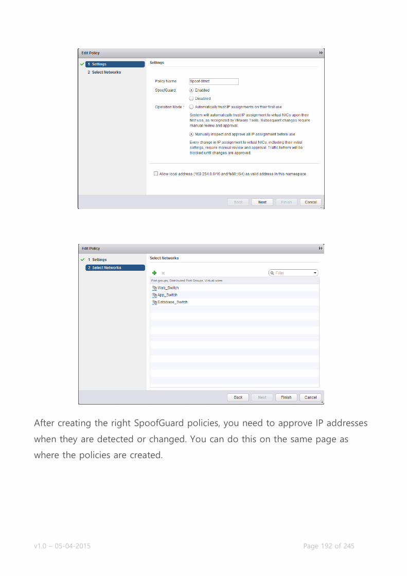
v1.0 – 05-04-2015 Page 192 of 245
After creating the right SpoofGuard policies, you need to approve IP addresses
when they are detected or changed. You can do this on the same page as
where the policies are created.
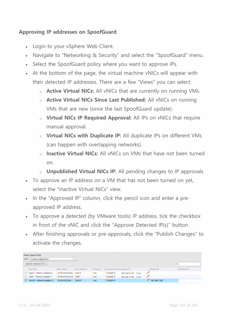
v1.0 – 05-04-2015 Page 193 of 245
Approving IP addresses on SpoofGuard
Login to your vSphere Web Client.
Navigate to “Networking & Security” and select the “SpoofGuard” menu.
Select the SpoofGuard policy where you want to approve IPs.
At the bottom of the page, the virtual machine vNICs will appear with
their detected IP addresses. There are a few “Views” you can select:
o Active Virtual NICs: All vNICs that are currently on running VMs.
o Active Virtual NICs Since Last Published: All vNICs on running
VMs that are new (since the last SpoofGuard update).
o Virtual NICs IP Required Approval: All IPs on vNICs that require
manual approval.
o Virtual NICs with Duplicate IP: All duplicate IPs on different VMs
(can happen with overlapping networks).
o Inactive Virtual NICs: All vNICs on VMs that have not been turned
on.
o Unpublished Virtual NICs IP: All pending changes to IP approvals
To approve an IP address on a VM that has not been turned on yet,
select the “Inactive Virtual NICs” view.
In the “Approved IP” column, click the pencil icon and enter a pre-
approved IP address.
To approve a detected (by VMware tools) IP address, tick the checkbox
in front of the vNIC and click the “Approve Detected IP(s)” button.
After finishing approvals or pre-approvals, click the “Publish Changes” to
activate the changes.
v1.0 – 05-04-2015 Page 194 of 245
Objective 6.2 – Configure and Administer Role Based Access Control
Implement identity service support for Active Directory, NIS, and LDAP
with Single Sign-On (SSO)
Configure/Modify/Delete user accounts
Configure/Modify/Delete user roles
Assign roles to user accounts
Disable/Enable user accounts
Role Based Access Control
The NSX Manager has its own authentication database and permission roles
you can assign to users. When installing NSX and linking the NSX Manager to
vCenter, the NSX Manager gets access to the vCenter authentication database
and single sign on is achieved for the vSphere Web Client. The vCenter user
you registered the NSX Manager will get the administrator role, but you will
need to grant additional users permission roles manually.
NSX Manager has four roles:
Auditor: This role can view settings, events and reports. A read-only
role.
Security Administrator: The Security Administrator can manage all
security related settings, such as the firewall services, NAT, SpoofGuard,
Security Groups, etc.
NSX Administrator: This role can deploy and configure NSX Edges,
Logical Switches, etc.
Enterprise Administrator: This role can do anything within NSX.
v1.0 – 05-04-2015 Page 195 of 245
The user system also has scopes, which allow granting permissions to a
specific NSX Edge. The scope definitions are: No restriction (access to all of
NSX), Limit access (access to a certain Edge). NSX 6.1 brings the port groups
and datacenters to the scope as well.
As with vCenter, you can register NSX Manager with a domain to enable SSO
between regular vCenter operations and the NSX management pane. You will
need to register this separately from the vCenter connections though. In the
upcoming tasks, we will register a domain and manage user accounts.
Implement identity service support for Active Directory, NIS, and LDAP with Single Sign-On (SSO)
Requirements:
NSX Environment.
VMware Documentation: Register a Windows Domain with NSX Manager
In this task, we will register a Windows domain to the NSX Manager so that
we can use the domain accounts for access to the NSX Management plane.
Registering a Windows domain to NSX Manager
Login to your vSphere Web Client.
Navigate to “Networking & Security” and select the “NSX Managers”
menu.
Choose the NSX Manager you want to modify, select the “Manage” tab
and select the “Domains” sub-tab.
Click the “+” icon to start the wizard to add a domain.

v1.0 – 05-04-2015 Page 196 of 245
On the first page, give the domain a name and provide its NetBIOS
Name. Click “Next” to continue.
Next provide the LDAP server details: Server IP or hostname, which
protocol to use (LDAP or secure LDAP(s)), which port to connect to and
domain credentials (which has access to add computers and read the
domain). Click “Next” to validate the settings.
If the domain connection succeeds (server reachable and right
credentials), you will get to the “Security Event Log Access” page. This
page determines on how NSX will retrieve security logs from the domain
server. You can do this via CIFS or WMI and optionally provide different
credentials to do so. When you’re ready, click “Next” to continue.
Lastly, review your settings on the “Ready to complete” page and click
“Finish” to add the domain.

v1.0 – 05-04-2015 Page 197 of 245
To enable SSO between vCenter and NSX Management, the Lookup Service
(SSO) needs to be registered in the NSX Manager. If this was already done
during the installation of NSX, great: you’re done! If not, follow these steps:
Registering NSX Manager to the Lookup Service
Login to your NSX Manager.
Navigate to “Manage Appliance Settings” and select the “NSX
Management Service” menu.
Click the “Edit” button in the “Lookup Service” table.
In the popup window, enter the Lookup Service IP (usually vCenter), the
port and the credentials to connect (usually
[email protected]). Click “OK” when you’re done.
When SSO is registered, the status should look like this:
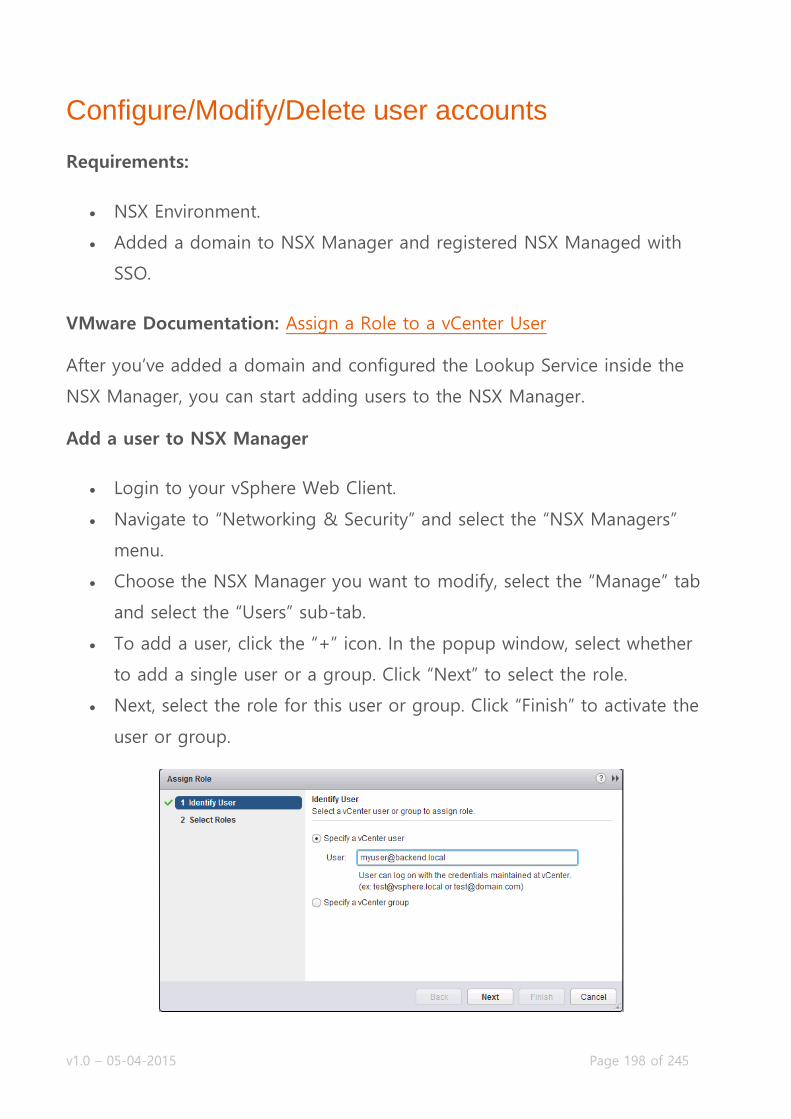
v1.0 – 05-04-2015 Page 198 of 245
Configure/Modify/Delete user accounts
Requirements:
NSX Environment.
Added a domain to NSX Manager and registered NSX Managed with
SSO.
VMware Documentation: Assign a Role to a vCenter User
After you’ve added a domain and configured the Lookup Service inside the
NSX Manager, you can start adding users to the NSX Manager.
Add a user to NSX Manager
Login to your vSphere Web Client.
Navigate to “Networking & Security” and select the “NSX Managers”
menu.
Choose the NSX Manager you want to modify, select the “Manage” tab
and select the “Users” sub-tab.
To add a user, click the “+” icon. In the popup window, select whether
to add a single user or a group. Click “Next” to select the role.
Next, select the role for this user or group. Click “Finish” to activate the
user or group.

v1.0 – 05-04-2015 Page 199 of 245
After adding users, you can only edit their role. So if you make a typo in the
username, delete the typoed username and just add the right one! Also, don’t
forget to give the user or group permissions inside vCenter itself; otherwise
they would not see the “Networking & Security” menu.
Configure/Modify/Delete user roles
Requirements:
NSX Environment.
Existing user to edit.
VMware Documentation: Change a User Role
Edit a users role
Login to your vSphere Web Client.
Navigate to “Networking & Security” and select the “NSX Managers”
menu.
Choose the NSX Manager you want to modify, select the “Manage” tab
and select the “Users” sub-tab.
Select the user you want to edit by clicking on it and click the “pencil”
icon to edit the user.
In the popup window, select their new role and click “Finish” to save.

v1.0 – 05-04-2015 Page 200 of 245
Assign roles to user accounts By completing the previous tasks, you will have completed this task as well,
hooray!
Disable/Enable user accounts
Requirements:
NSX Environment.
Existing user to enable or disable.
VMware Documentation: Disable or Enable a User Account
Once you’re created a few users or groups, let’s say you’re the NSX
administrator and you want to punish a colleague by temporarily taking away
the awesomeness of NSX. You can disable and enable specific users or groups,
without having to remove them (which makes you need to add them again
later).

v1.0 – 05-04-2015 Page 201 of 245
Disabling a NSX user
Login to your vSphere Web Client.
Navigate to “Networking & Security” and select the “NSX Managers”
menu.
Choose the NSX Manager you want to modify, select the “Manage” tab
and select the “Users” sub-tab.
Select the user or group you want to disable and click the “Disable” icon:
If you look at the “Status” column of the user table, you can tell whether a
user or group is currently enabled or disabled.
Enabling a NSX user
Login to your vSphere Web Client.
Navigate to “Networking & Security” and select the “NSX Managers”
menu.
Choose the NSX Manager you want to modify, select the “Manage” tab
and select the “Users” sub-tab.
Select the user or group you want to enable and click the “Enable” icon:

v1.0 – 05-04-2015 Page 202 of 245
Objective 6.3 – Configure and Manage Service Composer
Create/Modify/Delete Security Groups
Create/Modify/Delete Security Policies
Map Security Policies to Security Groups
Add/Assign/Edit/Delete Security Tags
View and manage effective services and failures for a Security Policy
Manage Security Policy priorities
Service Composer
Some say the Service Composer inside VMware is the most powerful feature
of the entire NSX platform, I tend to agree. With the service composer, you
can ‘compose’ chains of services which network traffic of a virtual machine is
directed through. For instance, you can construct a chain where the network
traffic of virtual machines that contain high sensitive data, automatically pass
through advanced firewalls (such as Palo Alto). Or automatically pushing web
servers towards advanced load balancers (such as F5).
The word automatically refers to the Security Groups. You might remember
these security groups from a few chapters back, from where the firewall
capabilities of NSX were discussed. To refresh the specifics: Security Groups
are groups of virtual machines that you can configure to be dynamically filled
with virtual machines. You can define criteria to match virtual machines on.
These criteria are: Computer OS Name, Computer Name, VM Name, Security
Tag, Entity (vSphere Object). Even more, you can match these criteria in a few
ways: you can enter text that the object should contain (“Contains”), what the
object should end with (“Ends with”), or the object should completely equal
(“Equals”), or the object should not equal to (“Not Equals To”), or what it
v1.0 – 05-04-2015 Page 203 of 245
should start with (“Starts With”). But wait, there’s even more! You can also use
multiple criteria and match any or all criteria specified.
Using these security groups, you can make a lot of imaginable matches. For
instance, you can create a group that has all virtual machines which are called
Web-XXX, have the ‘webfire’ tag, have the hostname
webfireXXXX.backend.local and run CentOS 6.1. Your imagination is the limit
here.
If you’ve got your security groups, you can attach Security Policies to them to
actually do something with the security groups. You might remember the
security groups from the distributed firewall as well, they have their own
distributed firewall section and can have specific firewall rules applied to them.
Besides from having special firewall rules, you can also specify Guest
Introspection Services and Network Introspection Services to them (these are
usually the third party services).
When you put the security groups and security policies together, you can
create a policed situation where a virtual machine that has a simple tag called
‘quarantine’ – it would be automatically put in a security group which is linked
to a security policy which in turn has specific firewall rules defined to
quarantine the virtual machine from the network. Pretty amazing, huh?
Let’s dive in to the tasks for this chapter.

v1.0 – 05-04-2015 Page 204 of 245
Create/Modify/Delete Security Groups
Requirements:
NSX Environment.
VMware Documentation: Create a Security Group in Service Composer
Let’s start with creating a simple security group which matches virtual
machines that have a name starting with ‘Web’
Registering a Windows domain to NSX Manager
Login to your vSphere Web Client.
Navigate to “Networking & Security” and select the “Service Composer”
menu.
Select the “Security Groups” tab and click the “+” icon to start the
wizard.
In the popup window, give your new security group a name, an optional
description and click “Next” to proceed.
The next page is where the magic happens, this is where you define the
criteria. In this example we’re only adding a single criteria, but you can
add as many as you want.
Add a criteria for the “VM Name”, select “Starts With” and enter “Web”
into the text field. Click “Next”.
Security Groups can have a scope to limit the gathering of virtual
machines (Other Security Groups, Cluster, Virtual wire, Network, Virtual
App, Datacenter, IP sets, AD groups, MAC Sets, Security tag, vNIC, Virtual
Machine, Resource Pool, Distributed Virtual Port Group). If you want to
limit the scope, configure the scope here. If you don’t want to limit the
scope, leave it unconfigured (as that uses global perspective). Click
“Next”.
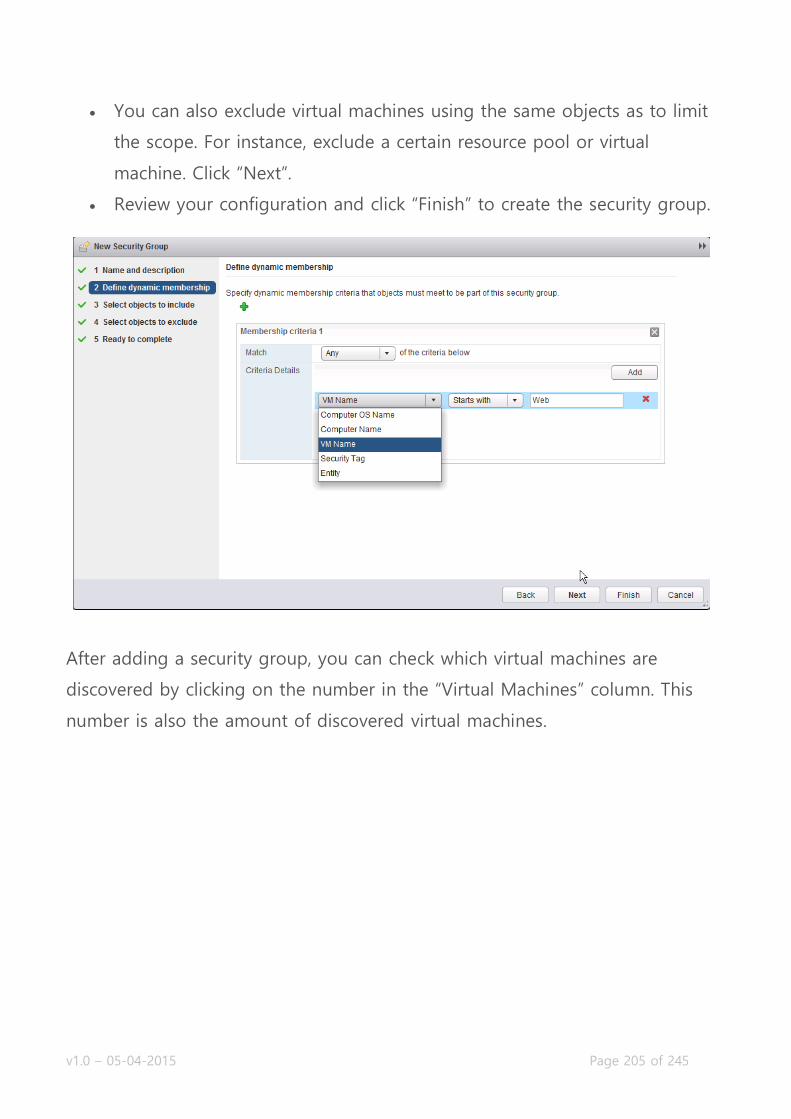
v1.0 – 05-04-2015 Page 205 of 245
You can also exclude virtual machines using the same objects as to limit
the scope. For instance, exclude a certain resource pool or virtual
machine. Click “Next”.
Review your configuration and click “Finish” to create the security group.
After adding a security group, you can check which virtual machines are
discovered by clicking on the number in the “Virtual Machines” column. This
number is also the amount of discovered virtual machines.

v1.0 – 05-04-2015 Page 206 of 245
Create/Modify/Delete Security Policies
Requirements:
NSX Environment.
VMware Documentation: Create a Security Policy
After creating the security group, you’ll want to do something with it. As
mentioned before, you can use them in firewall rules, but security policies is
what it’s really about.
Creating a Security Policy
Login to your vSphere Web Client.
Navigate to “Networking & Security” and select the “Service Composer”
menu.
Select the “Security Policies” tab and click the “+” icon to start the
wizard:
In the popup window, give the security policy and name and optional
description. You can also choose to inherit configuration from another
security policy here. Click “Next” when you’re done.
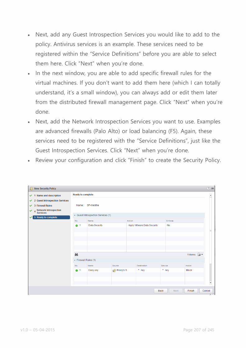
v1.0 – 05-04-2015 Page 207 of 245
Next, add any Guest Introspection Services you would like to add to the
policy. Antivirus services is an example. These services need to be
registered within the “Service Definitions” before you are able to select
them here. Click “Next” when you’re done.
In the next window, you are able to add specific firewall rules for the
virtual machines. If you don’t want to add them here (which I can totally
understand, it’s a small window), you can always add or edit them later
from the distributed firewall management page. Click “Next” when you’re
done.
Next, add the Network Introspection Services you want to use. Examples
are advanced firewalls (Palo Alto) or load balancing (F5). Again, these
services need to be registered with the “Service Definitions”, just like the
Guest Introspection Services. Click “Next” when you’re done.
Review your configuration and click “Finish” to create the Security Policy.

v1.0 – 05-04-2015 Page 208 of 245
Map Security Policies to Security Groups
Requirements:
NSX Environment.
Existing Security Group and Security Policy.
VMware Documentation: Map a Security Policy to a Security Group
After creating Security Groups and Security Policies, you might have noticed
that there’s no link between them yet. The relationship between a security
policy and security group is many to many. One security group can be
mapped to multiple security policies and one security policy can contain
multiple security groups. To create these mappings, do the following:
Create a Security Group to Security Policy relation
Login to your vSphere Web Client.
Navigate to “Networking & Security” and select the “Service Composer”
menu.
Select the “Security Policies” tab, select your security policy and click the
“Apply Security Policy” icon:
In the popup window, select the security groups to map and click “OK”
to apply your changes.

v1.0 – 05-04-2015 Page 209 of 245
Add/Assign/Edit/Delete Security Tags
Requirements:
NSX Environment.
VMware Documentation: Working with Security Tags
Security Tags are certain tags that a third party service (or VMware Data
Security) can put on a virtual machine. The most basic example is an Antivirus
scanner that tags a virtual machine with “Virus Found!”. You can create custom
security tags and apply them manually to virtual machines, but the most
sensible is to let the third party service create the tags and assign them, while
you just use them in security groups to match and police the virtual machines.
The whole concept is to automate these things.
But we still need to cover it because it’s on the blueprint, so lets go!

v1.0 – 05-04-2015 Page 210 of 245
Creating a custom Security Tag
Login to your vSphere Web Client.
Navigate to “Networking & Security” and select the “NSX Manager”
menu.
Select your NSX Manager and click the “Manage” tab, then the “Security
Tags” sub-tab.
Click the “New Security Tag” icon to add a new security tag:
In the name field, enter the entire tag name in a format as:
TagName=TagValue
Then enter an optional description and click “OK” to add the tag.
After creating the security tag, you can manually assign it to virtual machines
using this procedure:
Assigning a Security Tag
Login to your vSphere Web Client.
Navigate to “Networking & Security” and select the “NSX Manager”
menu.
Select your NSX Manager and click the “Manage” tab, then the “Security
Tags” sub-tab.
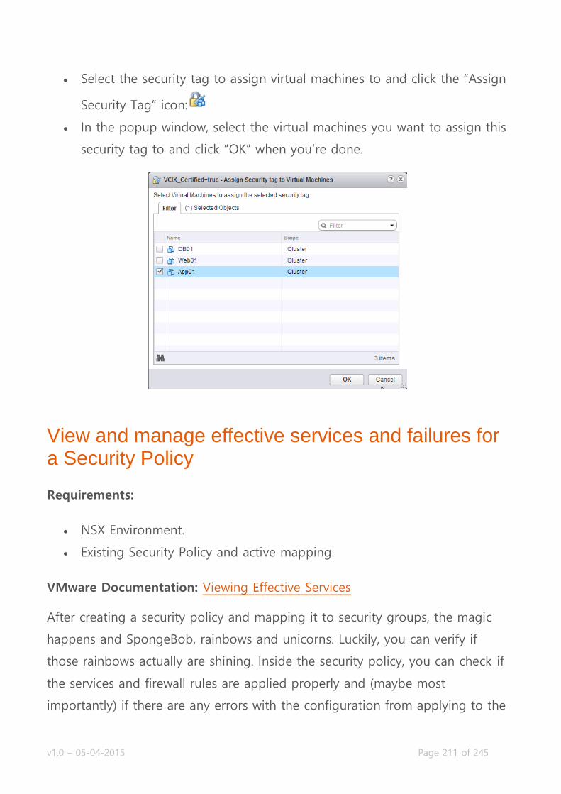
v1.0 – 05-04-2015 Page 211 of 245
Select the security tag to assign virtual machines to and click the “Assign
Security Tag” icon:
In the popup window, select the virtual machines you want to assign this
security tag to and click “OK” when you’re done.
View and manage effective services and failures for a Security Policy
Requirements:
NSX Environment.
Existing Security Policy and active mapping.
VMware Documentation: Viewing Effective Services
After creating a security policy and mapping it to security groups, the magic
happens and SpongeBob, rainbows and unicorns. Luckily, you can verify if
those rainbows actually are shining. Inside the security policy, you can check if
the services and firewall rules are applied properly and (maybe most
importantly) if there are any errors with the configuration from applying to the

v1.0 – 05-04-2015 Page 212 of 245
virtual infrastructure. Let’s start by verifying if the configuration has been
applied.
Check Security Policy settings
Login to your vSphere Web Client.
Navigate to “Networking & Security” and select the “Service Composer”
menu.
Select the “Security Policies” tab and double click the security policy you
want to check.
Inside the security policy, navigate to the “Manage” tab and select the
“Information Security” sub-tab.
Once there, you can double check and possibly edit the Guest
Introspection Services, Firewall Rules and Network Introspection Services.
Next, let’s check the enforcement of the security policy. Maybe there’s an error
actually applying the policy.
Check Security Policy application
Login to your vSphere Web Client.
Navigate to “Networking & Security” and select the “Service Composer”
menu.

v1.0 – 05-04-2015 Page 213 of 245
Select the “Security Policies” tab and double click the security policy you
want to check.
Inside the security policy, navigate to the “Monitor” tab and select the
“Service Errors” sub-tab.
If there are any errors, they should show here. If it’s empty, good! In the
example below, there’s an obvious reason for the VMware Data Security
service to not have applied on the virtual machine called Web01.
VMware Data Security is not installed.
Manage Security Policy priorities
Requirements:
NSX Environment.
Multiple Security Policies mapped to Security Groups.
VMware Documentation: Manage Security Policy Priority
Because you can map security policies to several security groups and a
security group could end up with multiple security policies, there’s a chance
that one security policy may override another security policy. They can
certainly complement each other (one security policy only for advanced
firewall service, another only for load balancing), so VMware has devised to
implement security policy priorities. Much like firewall rules, the security
policies act like on a first-come first-serve basis and you can arrange their
priorities. Here’s how:

v1.0 – 05-04-2015 Page 214 of 245
Re-ordering Security Policies
Login to your vSphere Web Client.
Navigate to “Networking & Security” and select the “Service Composer”
menu.
Select the “Security Policies” tab, select a security policy and click the
“Manage Priority: icon:
In the popup window, select a policy you want to move up or down and
click the “Move Up” or “Move Down” icons to do so:
Click “OK” when you’re done re-ordering.
v1.0 – 05-04-2015 Page 215 of 245
Objective 7.1 – Administer and Execute calls using the NSX vSphere API
Deploy and successfully authenticate an REST API client
Construct and execute an API call using correct syntax and formatting
Analyze, modify, and successfully retrieve configuration data using an
existing API call
NSX API
The NSX Platform management is an open door. Through the NSX API you
can deploy and configure all the different components. The API is used by
third party vendors to deliver services inside NSX, inside automation tools
(vRealize Automation) and for operational scripts.
To cover the VCIX-NV blueprint on the API, you need to know how to execute
basic API calls to get information and create basic objects. Don’t expect that
you need to be on the level of a developer (unless you’re developing an
application on top of NSX of course ). Especially if your area of expertise is
networking and you’re new to the application world, you need to play around
with this. Create a few basic things; a logical switch, edge gateway, hook a VM
to a logical switch, create a firewall rule, etc.
The API itself is located on the NSX Manager and goes through REST
(REpresentational State Transfer) with a XML format as the configuration body.
In non-developer speak: it uses different URLs for different operations
(simplified for example: /getuser, /create/edge) and you can use HTTP
operations such as GET (to retrieve information), POST (to push information,
create objects), PUT (modify objects) and DELETE (to delete objects). The
content of the call is structured in XML, details of which are specified in the
NSX API Guide. So for example, creating a logical switch would result in a
v1.0 – 05-04-2015 Page 216 of 245
POST to https://nsxmanager/api/2.0/services/securitygroup/bulk/globalroot-0
with the XML content from the guide.
REST API calls are usually done from a bit of code, but there are handy
browser plugins that allow you to do calls from inside your browser. Here are
my favorites:
Chrome: Postman
Firefox: RESTClient
All API calls have to be authenticated using credentials to login to the NSX
Manager. The credentials are encrypted using base64 and inserted into the
HTTP header.
Let’s dig in.
Deploy and successfully authenticate an REST API client
We start by downloading and installing the REST Client. In the upcoming
examples I’ll be using the Postman plugin in Chrome. The basic functionality
of the different plugins are the same though, so the screenshots should look
familiar on whichever you pick. Download and install a plugin of your choice
before proceeding.
After installing a REST plugin and before you start making API calls, make sure
the SSL certificate of the NSX Manager is trusted by your computer. If the NSX
Manager has a self-signed certificate, you need to install that certificate in the
trusted certificate store. If you do not do this and the SSL certificate is marked
as untrusted (you get a popup upon visiting the NSX Manager SSL webpage),
the REST Client will present you with a very non-descriptive error message
(something like “Server returned 0″).
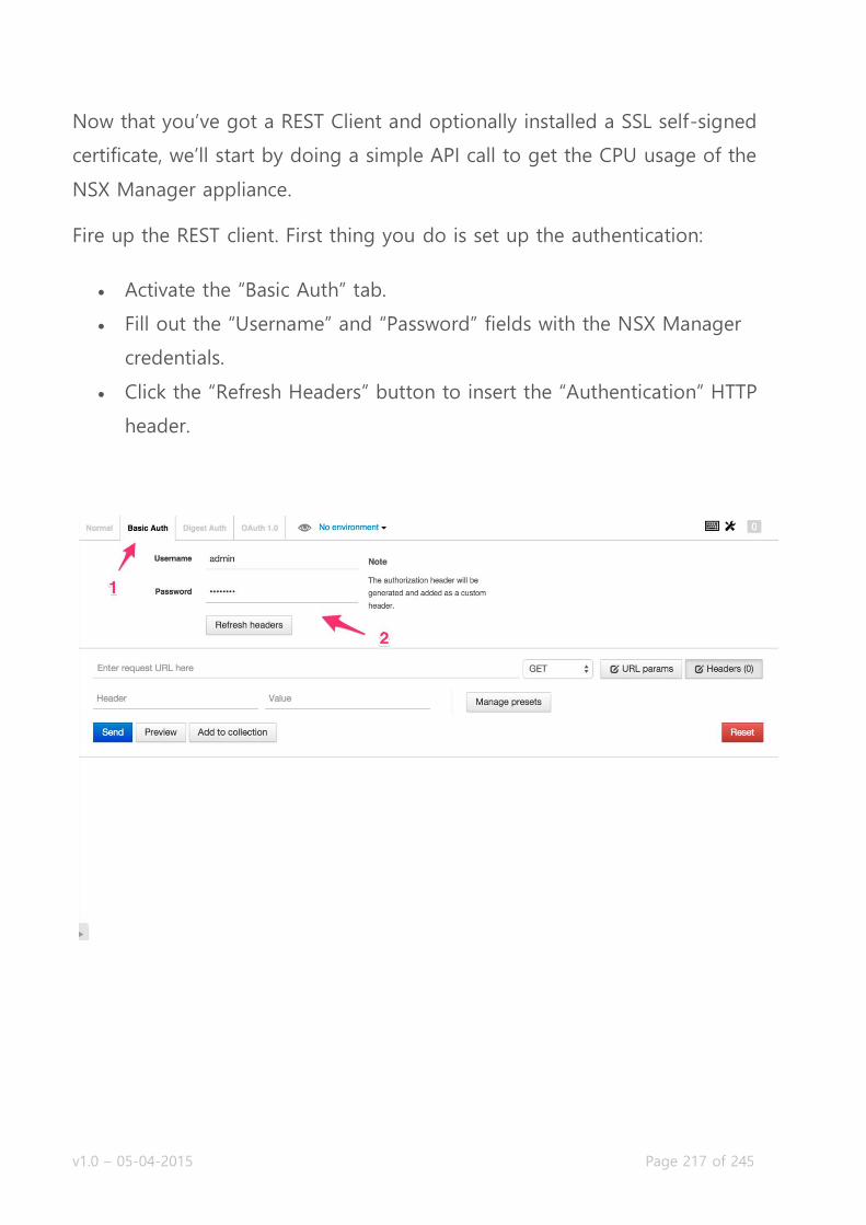
v1.0 – 05-04-2015 Page 217 of 245
Now that you’ve got a REST Client and optionally installed a SSL self-signed
certificate, we’ll start by doing a simple API call to get the CPU usage of the
NSX Manager appliance.
Fire up the REST client. First thing you do is set up the authentication:
Activate the “Basic Auth” tab.
Fill out the “Username” and “Password” fields with the NSX Manager
credentials.
Click the “Refresh Headers” button to insert the “Authentication” HTTP
header.

v1.0 – 05-04-2015 Page 218 of 245
After inserting the authentication header, you can move on to the actual API
call. Let’s get that CPU information!
Enter the API URL for the call you want to do. In this case that will
behttps://10.192.123.80/api/1.0/appliance-
management/system/cpuinfo. Check the NSX API Guide for the specific
URL for all the API calls you can execute.
Make sure the HTTP method select box is set to “GET” (which is the
default).
Click the “Send” button to send the HTTP request.
The output is formatted in JSON which can be parsed by any programming or
scripting language, or the naked eye. As you can see the NSX Manager had a
CPU load of 21% at the time of the call.

v1.0 – 05-04-2015 Page 219 of 245
Construct and execute an API call using correct syntax and formatting
The good news is that if you executed the API call in the previous bit, you
know how to do this – congratulations! But let’s go a bit further.
So getting information is pretty easy, all you need is a GET request to an URL.
Creating objects is a bit more complex and you need to do a tiny bit more to
pull that off. When pushing information to the API, an extra HTTP header
needs to be set: “Content-Type” with value “application/xml”. Next to the extra
header, the content (payload) needs to be formatted in the way NSX wants it.
It is formatted as XML and the contents are specified in the NSX API Guide.
Let’s do another example and add a NSX Security Tag. Here’s the formatted
XML:
<securityTag>
<objectTypeName>SecurityTag</objectTypeName>
<type>
<typeName>SecurityTag</typeName>
</type>
<name>My_Security_Tag_API</name>
<description>I just created this tag through the API!</description>
<extendedAttributes/>
</securityTag>
The properties of a Security Tag are pretty simplistic: a name and a
description, that’s it. The other tags around it are the formatted command to
create a security tag (that NSX API Guide is pretty important when you’re
doing this). Let’s execute it:

v1.0 – 05-04-2015 Page 220 of 245
After creating objects through the API, the returned result will mostly always
be the identifier of the object. You’ll notice that this is not the name, it is
usually the name of the type of object (in this case ‘securitytag’) and number.
Especially when modifying objects and creating objects that refer to other
objects (for example a new logical switch on a transport zone), these object
identifiers are important.
Back to the security tag. The API call output returned an object identifier,
which means the tag was created. When you double check in vCenter, you’ll
see that the security tag actually has been created:

v1.0 – 05-04-2015 Page 221 of 245
So now you’re able to get information from the NSX Manager and create
objects. Let’s move on to some more advanced stuff.
Analyze, modify, and successfully retrieve configuration data using an existing API call
To get a little deeper in the NSX API, we’re going to be adding several other
NSX components through the API. We’re going to be adding a NSX controller,
edge gateway and a logical switch.
If you’re adding objects that have relations to other vCenter objects, you need
to get the vCenter identifiers for those objects. I’m talking a bit abstract
because these objects have a very wide range. It can be a datacenter,
datastore, network portgroup or IP Pool. These are all objects that have
identifiers that we can use in API calls.
To retrieve object identifiers of existing vCenter objects, you can browse to
https://yourvcenter/mob. Login with admin credentials, click the “content” link
next to ServiceContent and look for the “rootFolder” row on the next page.
Click the link in that row. Finally, click the link next to “childObject” and you’ll
have most of the identifiers displayed on the next page.
Adding a NSX controller
Adding a controller is pretty straightforward, but you need quite a lot of info
before you can execute the API call. The call itself looks like this:
<controllerSpec>
<name>my-new-controller-api1</name>
<description>Created through the API</description>
<ipPoolId>ipaddresspool-1</ipPoolId>
<resourcePoolId>domain-c7</resourcePoolId>
<hostId>host-10</hostId>
<datastoreId>datastore-15</datastoreId>
<networkId>network-12</networkId>
<deployType>small</deployType>
<password>aPassword</password>
</controllerSpec>
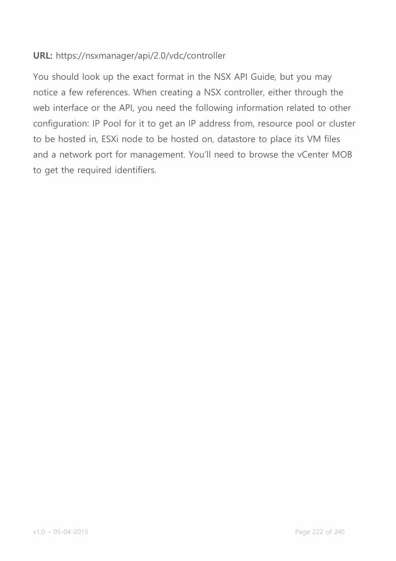
v1.0 – 05-04-2015 Page 222 of 245
URL: https://nsxmanager/api/2.0/vdc/controller
You should look up the exact format in the NSX API Guide, but you may
notice a few references. When creating a NSX controller, either through the
web interface or the API, you need the following information related to other
configuration: IP Pool for it to get an IP address from, resource pool or cluster
to be hosted in, ESXi node to be hosted on, datastore to place its VM files
and a network port for management. You’ll need to browse the vCenter MOB
to get the required identifiers.
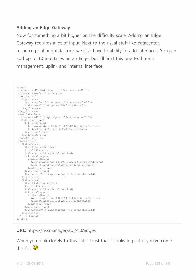
v1.0 – 05-04-2015 Page 223 of 245
Adding an Edge Gateway
Now for something a bit higher on the difficulty scale. Adding an Edge
Gateway requires a lot of input. Next to the usual stuff like datacenter,
resource pool and datastore, we also have to ability to add interfaces. You can
add up to 10 interfaces on an Edge, but I’ll limit this one to three: a
management, uplink and internal interface.
<edge>
<datacenterMoid>datacenter-2</datacenterMoid>
<type>gatewayServices</type>
<appliances>
<appliance>
<resourcePoolId>resgroup-8</resourcePoolId>
<datastoreId>datastore-15</datastoreId>
</appliance>
</appliances>
<mgmtInterface>
<connectedToId>dvportgroup-59</connectedToId>
<addressGroups>
<addressGroup>
<primaryAddress>10.192.123.84</primaryAddress>
<subnetMask>255.255.252.0</subnetMask>
</addressGroup>
</addressGroups>
</mgmtInterface>
<interfaces>
<interface>
<type>uplink</type>
<mtu>1500</mtu>
<isConnected>true</isConnected>
<addressGroups>
<addressGroup>
<primaryAddress>10.192.192.10</primaryAddress>
<subnetMask>255.255.255.252</subnetMask>
</addressGroup>
</addressGroups>
<connectedToId>dvportgroup-32</connectedToId>
</interface>
<interface>
<type>internal</type>
<mtu>1500</mtu>
<isConnected>true</isConnected>
<addressGroups>
<addressGroup>
<primaryAddress>192.168.0.1</primaryAddress>
<subnetMask>255.255.255.0</subnetMask>
</addressGroup>
</addressGroups>
<connectedToId>dvportgroup-43</connectedToId>
</interface>
</interfaces>
</edge>
URL: https://nsxmanager/api/4.0/edges
When you look closely to this call, I trust that it looks logical, if you’ve come
this far.
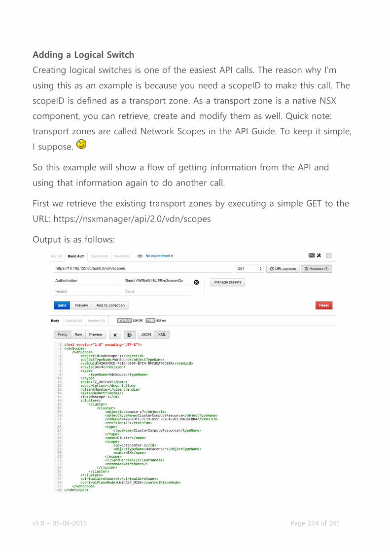
v1.0 – 05-04-2015 Page 224 of 245
Adding a Logical Switch
Creating logical switches is one of the easiest API calls. The reason why I’m
using this as an example is because you need a scopeID to make this call. The
scopeID is defined as a transport zone. As a transport zone is a native NSX
component, you can retrieve, create and modify them as well. Quick note:
transport zones are called Network Scopes in the API Guide. To keep it simple,
I suppose.
So this example will show a flow of getting information from the API and
using that information again to do another call.
First we retrieve the existing transport zones by executing a simple GET to the
URL: https://nsxmanager/api/2.0/vdn/scopes
Output is as follows:

v1.0 – 05-04-2015 Page 225 of 245
There’s only one transport zone in this testlab, so the output is easy to read. If
you’ve got multiple transport zones, there will be simply more <vdnScope>
entities defined. We need to get the <objectId> value for the next call, make a
note.
Next we create the logical switch by doing this call:
<virtualWireCreateSpec>
<name>t1-web-servers</name>
<description>Logical switch for T1 web servers</description>
<tenantId>Tenant 1</tenantId>
</virtualWireCreateSpec>
URL: https://nsxmanager/api/2.0/vdn/scopes/vdnscope-1/virtualwires (replace
the vdnscope-1with the transport zone object id)
If all goes well, the output of this call will be very slim. It’ll be just the logical
switch object identifier, formatted as virtualwire-#. Here’s the example in
Postman:
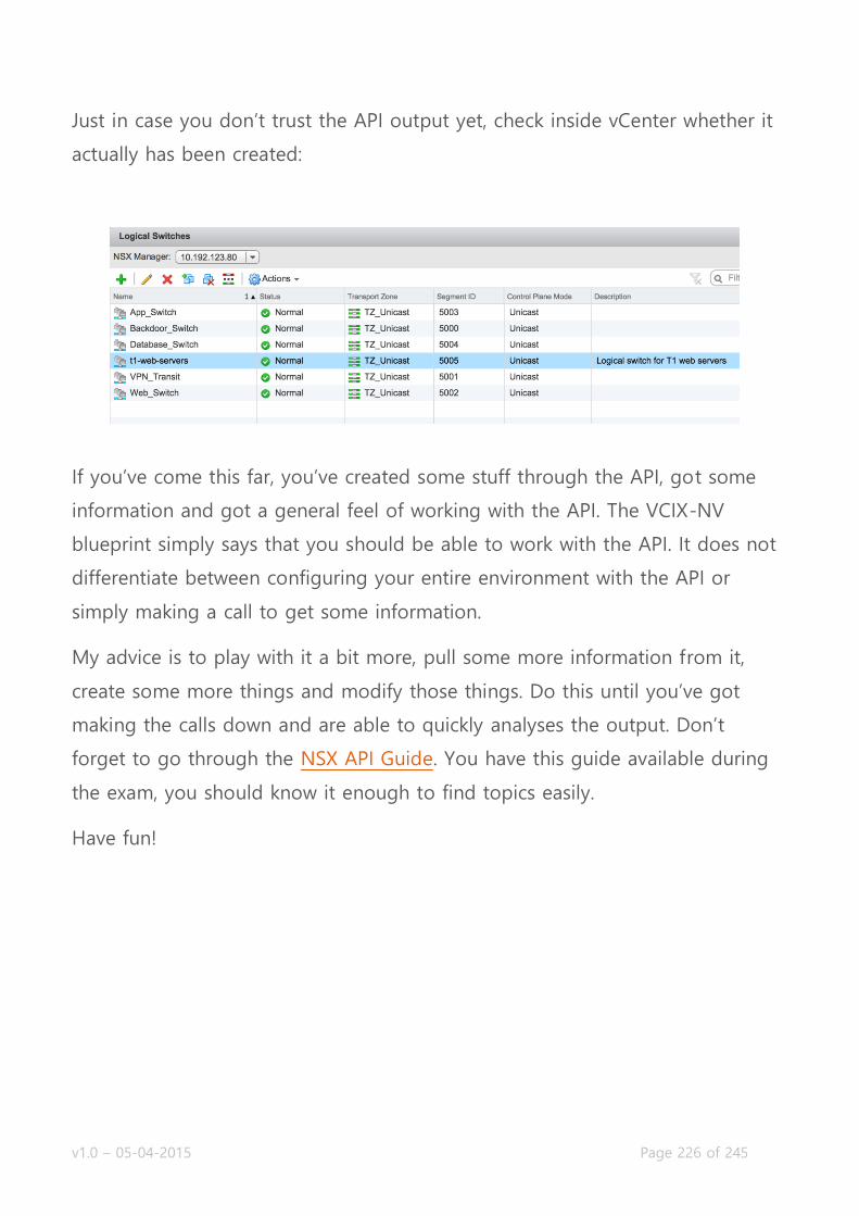
v1.0 – 05-04-2015 Page 226 of 245
Just in case you don’t trust the API output yet, check inside vCenter whether it
actually has been created:
If you’ve come this far, you’ve created some stuff through the API, got some
information and got a general feel of working with the API. The VCIX-NV
blueprint simply says that you should be able to work with the API. It does not
differentiate between configuring your entire environment with the API or
simply making a call to get some information.
My advice is to play with it a bit more, pull some more information from it,
create some more things and modify those things. Do this until you’ve got
making the calls down and are able to quickly analyses the output. Don’t
forget to go through the NSX API Guide. You have this guide available during
the exam, you should know it enough to find topics easily.
Have fun!

v1.0 – 05-04-2015 Page 227 of 245
Objective 7.2 – Manage and Report on an NSX Environment using the NSX Command Line Interface
Manage and report on an NSX installation status using ESXi Command
Line Interface (CLI) commands
Manage and report on an NSX Infrastructure using NSX Manager, NSX
Controller, and ESXi CLI commands
Manage and report on a Logical Switch using NSX Controller and ESXi
CLI commands
Manage and report on a Logical Router NSX Controller, NSX Edge, and
ESXi CLI commands
Manage and report on a Distributed Firewall using NSX Manager and
ESXi CLI commands
Manage and report on an Edge Services VPN-Plus device using NSX
Edge and client OS CLI commands
Manage and report on Load Balancers using NSX Edge CLI commands
Command Line Interface on NSX
Traditional network infrastructure is managed via command line. Every network
administrator out there is glued to the command line for configuration,
troubleshooting and setup tasks. Even though this is changing by all kinds of
automation tools out there that present a GUI (ACI, APIC-EM, NSX, OpenFlow
GUIs, etc), most of them retain some form of command line interface (CLI).
VMware NSX is no different.
v1.0 – 05-04-2015 Page 228 of 245
NSX offers command line interfaces on the following:
NSX Manager
NSX Controller
NSX Edge Gateway Services appliance
NSX Logical Distributed Router
ESXi host (existing, but added functionality for NSX)
There are way too many useful commands to cover them as a whole, so I
recommend fully to read the entire (yes entire!@#) NSX Command Line
Interface Reference. As for me, as usual the topics are laid out from the VCIX-
NV blueprint and I’ll be share the most useful commands there are, to
kickstart the process.
If you’re not a network administrator, please keep in mind that the console
prompt displayed like this device> is called exec mode, which you get into by
default when logging into a device. The console prompt displayed
like device# is enabled mode, which you can get to by using the enable
command and entering your password again. The examples below are
displayed in both exec and enabled mode, it’s up to you to get there.
You should also check out the brilliant post by Sébastien Braun on NSX
vSphere troubleshooting, as it has a lot of useful commands.

v1.0 – 05-04-2015 Page 229 of 245
Manage and report on an NSX installation status using ESXi Command Line Interface (CLI) commands
Manage and report on an NSX Infrastructure using NSX Manager, NSX Controller, and ESXi CLI commands
We’re going to run through the NSX components top to bottom and have a
look at some CLI outputs and change some stuff. While I’m going through, I’m
going to assume that by know you know to login via SSH onto the NSX
component that is referenced.
NSX Manager
You do not have the entire functionality of the NSX Manager at your disposal
via the CLI. There does not seem to be a way to manage the integration with
vCenter and SSO, among others. Let’s start by looking at the basic system
configuration:
nsx-manager# show running-config
Building configuration...
Current configuration:
!
ntp server nl.pool.ntp.org
!
ip name server 8.8.8.8
!
hostname nsx-manager
!
interface mgmt
ip address 10.192.123.80/24
!
ip route 0.0.0.0/0 10.192.123.1
!
web-manager
nsx-manager#
You need to be in enabled mode to show or modify anything configuration
related. Somewhat like a regular switch, the output shows the DNS, NTP and
IP configuration of the NSX Manager. If you’d like to change something, let’s

v1.0 – 05-04-2015 Page 230 of 245
say the IP address of the NSX Manager, first go into configuration mode and
set a new IP address:
nsx-manager# configure terminal
nsx-manager(config)# interface mgmt
nsx-manager(config-if)# ip address 10.192.123.90/24
Not sure if this remark is needed, but if you do this, you’ll lose your
connection and you’ll need to set up the SSH connection again. With any
other switch-type interface, you need to save the changes to the startup
configuration file to save it permanently.
nsx-manager# write memory
Building Configuration...
Configuration saved. [OK]
nsx-manager#
Using the CLI is a good way to get detailed logging from the NSX Manager:
nsx-manager> show manager log reverse
2015-01-17 19:04:45.384 CET INFO pool-23-thread-1 EndpointConfigurationManagerImpl:812 - scheduleConf
igurationUpdateCheck: scheduling update check in 60 seconds.
2015-01-17 19:04:45.384 CET INFO pool-23-thread-1 EndpointConfigurationManagerImpl:1174 - No USVM is
defined for host host-16 - will retry
2015-01-17 19:04:45.384 CET INFO pool-23-thread-1 EndpointConfigurationManagerImpl:1482 - USVM is not
configured for host host-16
NSX Controller
The NSX Controllers are a Linux-based appliance that contains all information
of the virtual network, it retains and controls the active state of your network.
Edges are registered here, along with their interfaces and routes. When
requesting information from a controller cluster, make sure you connect to the
master.
Let’s start by getting the controller cluster state:
nsx-controller # show control-cluster status
Type Status Since
--------------------------------------------------------------------------------
Join status: Join complete 01/16 15:06:25
Majority status: Connected to cluster majority 01/17 06:22:37
Restart status: This controller can be safely restarted 01/17 06:22:27
Cluster ID: 95e35052-cd43-4688-a8b3-910ce0fd50d7
Node UUID: aadd57da-0d39-4377-a011-5abfd0620ebf
Role Configured status Active status
--------------------------------------------------------------------------------
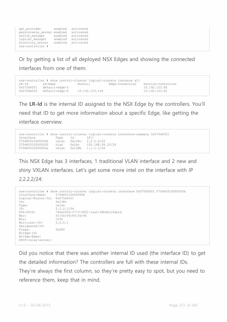
v1.0 – 05-04-2015 Page 231 of 245
api_provider enabled activated
persistence_server enabled activated
switch_manager enabled activated
logical_manager enabled activated
directory_server enabled activated
nsx-controller #
Or by getting a list of all deployed NSX Edges and showing the connected
interfaces from one of them:
nsx-controller # show control-cluster logical-routers instance all
LR-Id LR-Name Hosts[] Edge-Connection Service-Controller
0x570d4551 default+edge-5 10.192.123.82
0x570d4552 default+edge-4 10.192.123.104 10.192.123.81
The LR-Id is the internal ID assigned to the NSX Edge by the controllers. You’ll
need that ID to get more information about a specific Edge, like getting the
interface overview:
nsx-controller # show control-cluster logical-routers interface-summary 0x570d4551
Interface Type Id IP[]
570d45510000000b vxlan 0x138c 2.2.2.2/24
570d455100000002 vlan 0x1bc 192.168.99.10/24
570d45510000000a vxlan 0x138b 1.1.1.1/24
This NSX Edge has 3 interfaces, 1 traditional VLAN interface and 2 new and
shiny VXLAN interfaces. Let’s get some more intel on the interface with IP
2.2.2.2/24:
nsx-controller # show control-cluster logical-routers interface 0x570d4551 570d45510000000b
Interface-Name: 570d45510000000b
Logical-Router-Id: 0x570d4551
Id: 0x138c
Type: vxlan
IP: 2.2.2.2/24
DVS-UUID: 78dc0350-3773-5831-1aaf-f8b44c18decd
Mac: 02:50:56:83:3d:66
Mtu: 1500
Multicast-IP: 0.0.0.1
Designated-IP:
Flags: 0x280
Bridge-Id:
Bridge-Name:
DHCP-relay-server:
Did you notice that there was another internal ID used (the interface ID) to get
the detailed information? The controllers are full with these internal IDs.
They’re always the first column, so they’re pretty easy to spot, but you need to
reference them, keep that in mind.

v1.0 – 05-04-2015 Page 232 of 245
NSX Edge Services Gateway
Of the two types of NSX Edges, the ESG and LDR. When you’re on the CLI,
you don’t see a lot of difference, apart from the ESG having a lot more
commands (simply because it has more functionality). The following examples
are mostly applicable to both, unless otherwise is mentioned. The CLI of both
Edge types are meant for showing information and debugging traffic flow,
there is no real configuration possible.
Let’s get a list of interfaces to start. NSX Edges are deployed with a number of
interfaces, whether or not you decide to use them. This means the output of
getting the interfaces can be huge, even though you thought you just
configured 2 interfaces.
vShield-edge-2-0> show interface
Interface VDR is up, line protocol is up
index 2 metric 1 mtu 1500 <UP,BROADCAST,RUNNING,NOARP>
...snip...
Interface br-sub is up, line protocol is up
...snip...
Interface lo is up, line protocol is up
...snip...
Interface vNic_0 is up, line protocol is up
index 3 metric 1 mtu 1500 <UP,BROADCAST,RUNNING,MULTICAST>
HWaddr: 00:50:56:83:48:7b
inet6 fe80::250:56ff:fe83:487b/64
inet 10.192.123.88/24
proxy_arp: disabled
Auto-duplex (Full), Auto-speed (2191Mb/s)
input packets 116733, bytes 7800485, dropped 9378, multicast packets 6
input errors 0, length 0, overrun 0, CRC 0, frame 0, fifo 0, missed 0
output packets 21624, bytes 2151234, dropped 0
output errors 0, aborted 0, carrier 0, fifo 0, heartbeat 0, window 0
collisions 0
Interface vNic_4 is up, line protocol is up
index 4 metric 1 mtu 1500 <UP,BROADCAST,RUNNING,MULTICAST>
HWaddr: 00:50:56:83:dc:35
inet 10.1.5.12/24
...snip...
Interface vNic_8 is down
...snip...
Interface vNic_1 is up, line protocol is up
...etc...
Regular interfaces are called vNic_X, but you’ll notice a few other interfaces
listed in the output. TheVDR interface is the Virtual Distributed Router (or
LDR), the br-sub interface is the Layer 2 VPN tunnel interface and
the lo interface is a loopback interface which can be used in routing protocol
configuration (just like regular routers).

v1.0 – 05-04-2015 Page 233 of 245
We got the interfaces, let’s see if there are any ARP entries for connected
hosts:
vShield-edge-2-0> show arp
-----------------------------------------------------------------------
vShield Edge ARP Cache:
IP Address Interface MAC Address State
10.192.123.1 vNic_0 00:00:0c:9f:f0:59 REACHABLE
192.168.1.200 vNic_1 00:50:56:83:b3:df REACHABLE
What about the routing table which the Edge uses to make routing decisions?
vShield-edge-2-0> show ip route
Codes: O - OSPF derived, i - IS-IS derived, B - BGP derived, C - connected, S - static, L1 - IS-IS l
evel-1, L2 - IS-IS level-2, IA - OSPF inter area, E1 - OSPF external type 1, E2 - OSPF external type
2, N1 - OSPF NSSA external type 1, N2 - OSPF NSSA external type 2
Total number of routes: 7
S 0.0.0.0/0 [1/1] via 10.192.123.1
C 1.1.1.0/24 [0/0] via 1.1.1.1
C 2.2.2.0/24 [0/0] via 2.2.2.1
C 10.1.5.0/24 [0/0] via 10.1.5.12
C 10.192.123.0/24 [0/0] via 10.192.123.88
C 192.168.1.0/24 [0/0] via 192.168.1.1
C 192.168.99.0/24 [0/0] via 192.168.99.1
One particularly handy command on the ESG is to show the firewall flows to
show top network consumers:
vShield-edge-2-0> show firewall flows topN 2
...snip...
Chain usr_rules (2 references)
rid pkts bytes target prot opt in out source destination
131073 288 19902 ACCEPT all -- * * 0.0.0.0/0 0.0.0.0/0
------ flow info for rule 131073 ------
1: icmp 1 9 src=192.168.1.200 dst=74.125.71.139 type=8 code=0 id=37382 pkts=20757 bytes=1743588 src=7
4.125.71.139 dst=10.192.123.88 type=0 code=0 id=37382 pkts=20757 bytes=1743588 mark=2048 rid=131073 u
se=1
2: tcp 6 3599 ESTABLISHED src=10.192.120.150 dst=10.192.123.88 sport=1590 dport=22 pkts=1166 bytes=98
156 src=10.192.123.88 dst=10.192.120.150 sport=22 dport=1590 pkts=1031 bytes=152413 [ASSURED] mark=20
48 rid=131073 use=1
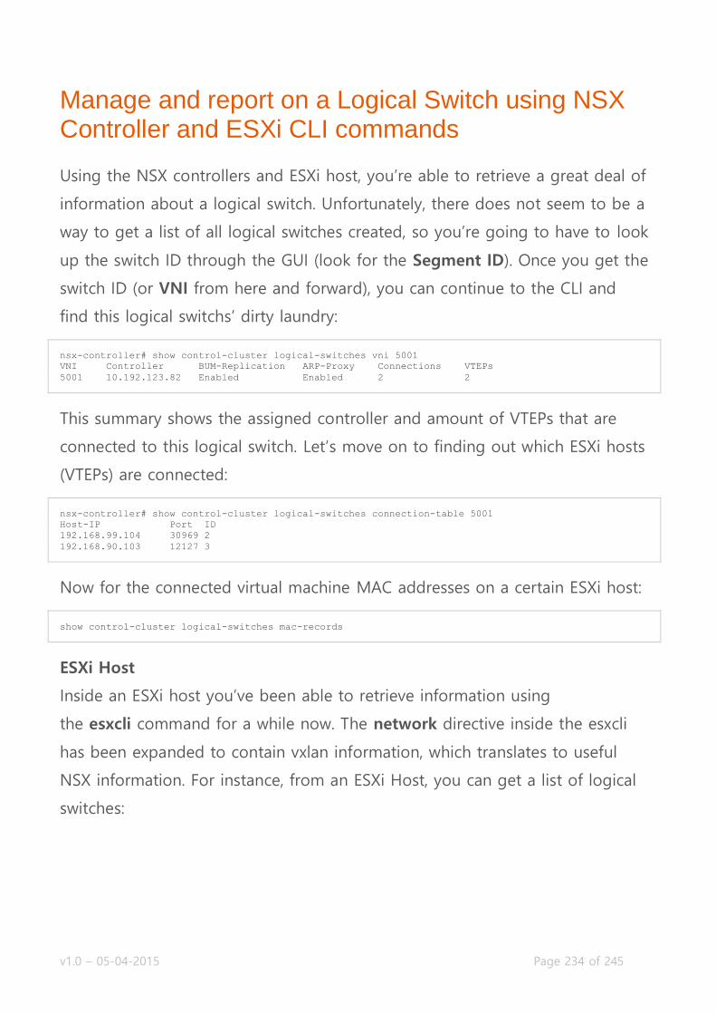
v1.0 – 05-04-2015 Page 234 of 245
Manage and report on a Logical Switch using NSX Controller and ESXi CLI commands
Using the NSX controllers and ESXi host, you’re able to retrieve a great deal of
information about a logical switch. Unfortunately, there does not seem to be a
way to get a list of all logical switches created, so you’re going to have to look
up the switch ID through the GUI (look for the Segment ID). Once you get the
switch ID (or VNI from here and forward), you can continue to the CLI and
find this logical switchs’ dirty laundry:
nsx-controller# show control-cluster logical-switches vni 5001
VNI Controller BUM-Replication ARP-Proxy Connections VTEPs
5001 10.192.123.82 Enabled Enabled 2 2
This summary shows the assigned controller and amount of VTEPs that are
connected to this logical switch. Let’s move on to finding out which ESXi hosts
(VTEPs) are connected:
nsx-controller# show control-cluster logical-switches connection-table 5001
Host-IP Port ID
192.168.99.104 30969 2
192.168.90.103 12127 3
Now for the connected virtual machine MAC addresses on a certain ESXi host:
show control-cluster logical-switches mac-records
ESXi Host
Inside an ESXi host you’ve been able to retrieve information using
the esxcli command for a while now. The network directive inside the esxcli
has been expanded to contain vxlan information, which translates to useful
NSX information. For instance, from an ESXi Host, you can get a list of logical
switches:
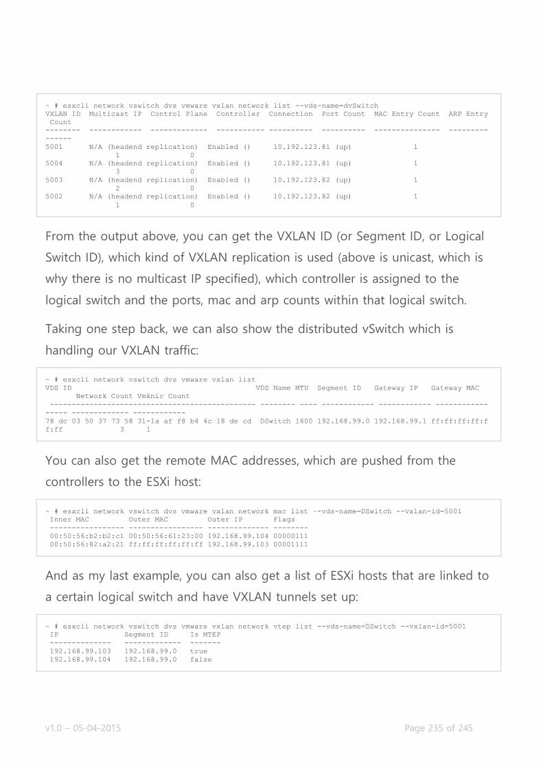
v1.0 – 05-04-2015 Page 235 of 245
~ # esxcli network vswitch dvs vmware vxlan network list --vds-name=dvSwitch
VXLAN ID Multicast IP Control Plane Controller Connection Port Count MAC Entry Count ARP Entry
Count
-------- ------------ ------------- ----------- ---------- ---------- --------------- ---------
------
5001 N/A (headend replication) Enabled () 10.192.123.81 (up) 1
1 0
5004 N/A (headend replication) Enabled () 10.192.123.81 (up) 1
3 0
5003 N/A (headend replication) Enabled () 10.192.123.82 (up) 1
2 0
5002 N/A (headend replication) Enabled () 10.192.123.82 (up) 1
1 0
From the output above, you can get the VXLAN ID (or Segment ID, or Logical
Switch ID), which kind of VXLAN replication is used (above is unicast, which is
why there is no multicast IP specified), which controller is assigned to the
logical switch and the ports, mac and arp counts within that logical switch.
Taking one step back, we can also show the distributed vSwitch which is
handling our VXLAN traffic:
~ # esxcli network vswitch dvs vmware vxlan list
VDS ID VDS Name MTU Segment ID Gateway IP Gateway MAC
Network Count Vmknic Count
----------------------------------------------- -------- ---- ------------ ------------ ------------
----- ------------- ------------
78 dc 03 50 37 73 58 31-1a af f8 b4 4c 18 de cd DSwitch 1600 192.168.99.0 192.168.99.1 ff:ff:ff:ff:f
f:ff 3 1
You can also get the remote MAC addresses, which are pushed from the
controllers to the ESXi host:
~ # esxcli network vswitch dvs vmware vxlan network mac list –-vds-name=DSwitch --vxlan-id=5001
Inner MAC Outer MAC Outer IP Flags
----------------- ----------------- -------------- --------
00:50:56:b2:b2:c1 00:50:56:61:23:00 192.168.99.104 00000111
00:50:56:82:a2:21 ff:ff:ff:ff:ff:ff 192.168.99.103 00001111
And as my last example, you can also get a list of ESXi hosts that are linked to
a certain logical switch and have VXLAN tunnels set up:
~ # esxcli network vswitch dvs vmware vxlan network vtep list --vds-name=DSwitch --vxlan-id=5001
IP Segment ID Is MTEP
-------------- ------------- -------
192.168.99.103 192.168.99.0 true
192.168.99.104 192.168.99.0 false

v1.0 – 05-04-2015 Page 236 of 245
Manage and report on a Logical Router NSX Controller, NSX Edge, and ESXi CLI commands
We’ve already covered retrieving logical router information from the NSX
Controller in the first topic on this page, so we’re going to go straight to the
NSX Edge itself.
There are a few commands that you might use in an operational sense. Most
of them we’ve already covered in other topics, so I’m going to just list them:
Show attached hosts:
vShield-edge-11-0> show arp
-----------------------------------------------------------------------
vShield Edge ARP Cache:
IP Address Interface MAC Address State
10.192.123.1 vNic_0 00:00:0c:9f:f0:59 REACHABLE
vShield-edge-11-0>
Show installed routing table:
vShield-edge-11-0> show ip route
Codes: O - OSPF derived, i - IS-IS derived, B - BGP derived, C - connected, S - static, L1 - IS-IS
level-1, L2 - IS-IS level-2, IA - OSPF inter area, E1 - OSPF external type 1, E2 - OSPF external type
2, N1 - OSPF NSSA external type 1, N2 - OSPF NSSA external type 2
Total number of routes: 4
S 0.0.0.0/0 [1/1] via 10.192.123.1
C 10.192.123.0/24 [0/0] via 10.192.123.78
C 192.168.1.0/24 [0/0] via 192.168.1.1
C 192.168.2.0/24 [0/0] via 192.168.2.1
Show attached interfaces:
vShield-edge-11-0> show interface
Interface VDR is up, line protocol is up
index 2 metric 1 mtu 1500 <UP,BROADCAST,RUNNING,NOARP>
HWaddr: 96:b4:01:91:36:1b
inet6 fe80::94b4:1ff:fe91:361b/64
inet 192.168.1.1/24
...snip...

v1.0 – 05-04-2015 Page 237 of 245
Show current network flows:
vShield-edge-11-0> show firewall flows
Chain PREROUTING (policy ACCEPT 26240 packets, 3473K bytes)
rid pkts bytes target prot opt in out source destination
Chain INPUT (policy ACCEPT 25689 packets, 3406K bytes)
rid pkts bytes target prot opt in out source destination
Chain FORWARD (policy ACCEPT 0 packets, 0 bytes)
rid pkts bytes target prot opt in out source destination
Chain OUTPUT (policy ACCEPT 24301 packets, 3356K bytes)
rid pkts bytes target prot opt in out source destination
Chain POSTROUTING (policy ACCEPT 24301 packets, 3356K bytes)
rid pkts bytes target prot opt in out source destination
ESXi Host Commands
As the distributed router is embedded in the ESXi kernel, the ESXi host needs
to know about its configuration in other to handle local routing traffic. This
means that the routing info that the LDR Control VM collects, is pushed down
to the ESXi host, so it can make informed decisions on where to send traffic.
VMware has extended the CLI on ESXi so you can pull that information out. I’ll
walk you through some of the most used ones. One thing to note is that ‘LDR’
(logical distributed router) in terminology translated to VDR (virtual distributed
router) inside ESXi. Let’s start with getting an overview of the logical router
instances that are located on the host:
~ # net-vdr --instance –l
VDR Instance Information :
---------------------------
Vdr Name: default+edge-11
Vdr Id: 1969527526
Number of Lifs: 5
Number of Routes: 4
State: Enabled
Controller IP: 10.192.123.81
Control Plane IP: 10.192.123.103
Control Plane Active: Yes
Num unique nexthops: 1
Generation Number: 0
Edge Active: Yes

v1.0 – 05-04-2015 Page 238 of 245
Once you get the edge identifier, you can look up the interfaces of this NSX
Edge, or the logical interfaces (lif):
~ # net-vdr --lif -l default+edge-11
VDR default+edge-11 LIF Information :
Name: 75649ae600000002
Mode: Routing, Distributed, Uplink
Id: Vlan: 495
Ip(Mask): 10.192.123.77(255.255.255.0)
Connected Dvs: DSwitch
Designated Instance: Yes
DI IP: 10.192.123.103
State: Enabled
Flags: 0x8
DHCP Relay: Not enabled
Name: 75649ae60000000b
Mode: Routing, Distributed, Internal
Id: Vlan: 444
Ip(Mask): 192.168.2.1(255.255.255.0)
Connected Dvs: DSwitch
Designated Instance: Yes
DI IP: 10.192.123.103
State: Enabled
Flags: 0x88
DHCP Relay: Not enabled
Name: 75649ae60000000a
Mode: Routing, Distributed, Internal
Id: Vlan: 333
Ip(Mask): 192.168.1.1(255.255.255.0)
Connected Dvs: DSwitch
Designated Instance: Yes
DI IP: 10.192.123.103
State: Enabled
Flags: 0x88
DHCP Relay: Not enabled
As mentioned, the ESXi host knows about the routes the LDR has, so it can
make the informed decision on where to route the traffic. If it can do a local
route, it will. To verify the network routes installed in the LDR, you can use the
following command:
~ # net-vdr --route -l default+edge-11
VDR default+edge-11
Route Table Legend: [U: Up], [G: Gateway], [C: Connected], [I: Interface] Legend: [H: Host], [F: Sof
t Flush] [!: Reject] [E: ECMP]
Destination GenMask Gateway Flags Ref Origin UpTime Interface
----------- ------- ------- ----- --- ------ ------ ---------
0.0.0.0 0.0.0.0 10.192.123.1 UG 1 AUTO 120 75649ae600000002
10.192.123.0 255.255.255.0 0.0.0.0 UCI 1 MANUAL 126 75649ae600000002
192.168.1.0 255.255.255.0 0.0.0.0 UCI 1 MANUAL 126 75649ae60000000a
192.168.2.0 255.255.255.0 0.0.0.0 UCI 1 MANUAL 126 75649ae60000000b
Now you have the most important information for the routing of the logical
distributed router inside the ESXi kernel. There’s another functionality that the
LDR can perform; bridging of VXLAN and VLAN networks. We talked about
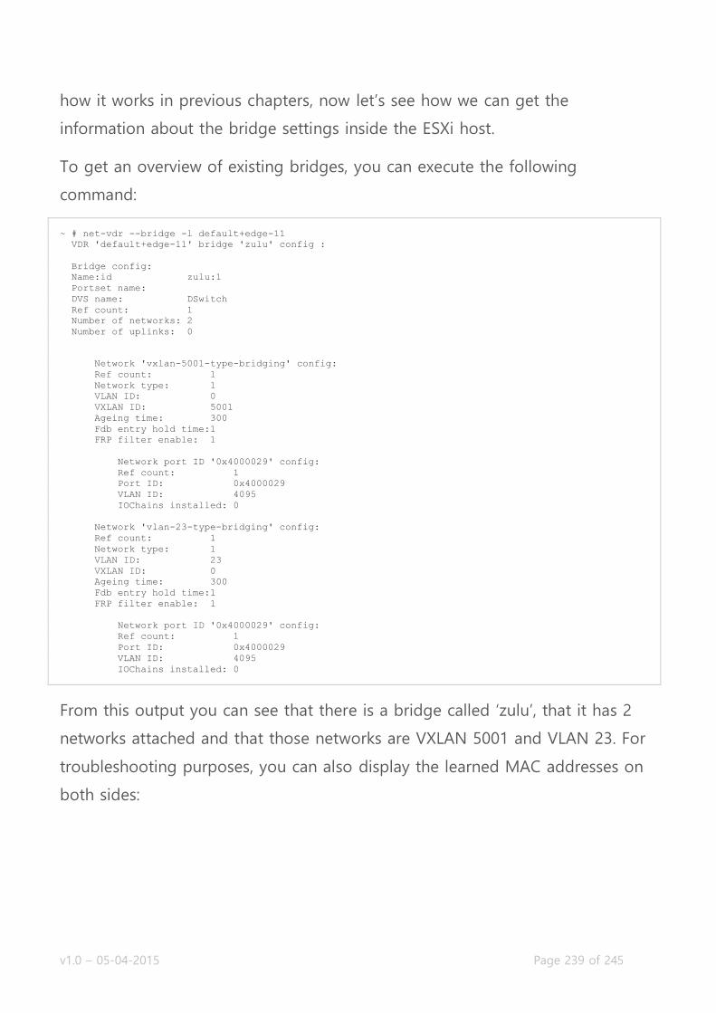
v1.0 – 05-04-2015 Page 239 of 245
how it works in previous chapters, now let’s see how we can get the
information about the bridge settings inside the ESXi host.
To get an overview of existing bridges, you can execute the following
command:
~ # net-vdr --bridge -l default+edge-11
VDR 'default+edge-11' bridge 'zulu' config :
Bridge config:
Name:id zulu:1
Portset name:
DVS name: DSwitch
Ref count: 1
Number of networks: 2
Number of uplinks: 0
Network 'vxlan-5001-type-bridging' config:
Ref count: 1
Network type: 1
VLAN ID: 0
VXLAN ID: 5001
Ageing time: 300
Fdb entry hold time:1
FRP filter enable: 1
Network port ID '0x4000029' config:
Ref count: 1
Port ID: 0x4000029
VLAN ID: 4095
IOChains installed: 0
Network 'vlan-23-type-bridging' config:
Ref count: 1
Network type: 1
VLAN ID: 23
VXLAN ID: 0
Ageing time: 300
Fdb entry hold time:1
FRP filter enable: 1
Network port ID '0x4000029' config:
Ref count: 1
Port ID: 0x4000029
VLAN ID: 4095
IOChains installed: 0
From this output you can see that there is a bridge called ‘zulu’, that it has 2
networks attached and that those networks are VXLAN 5001 and VLAN 23. For
troubleshooting purposes, you can also display the learned MAC addresses on
both sides:
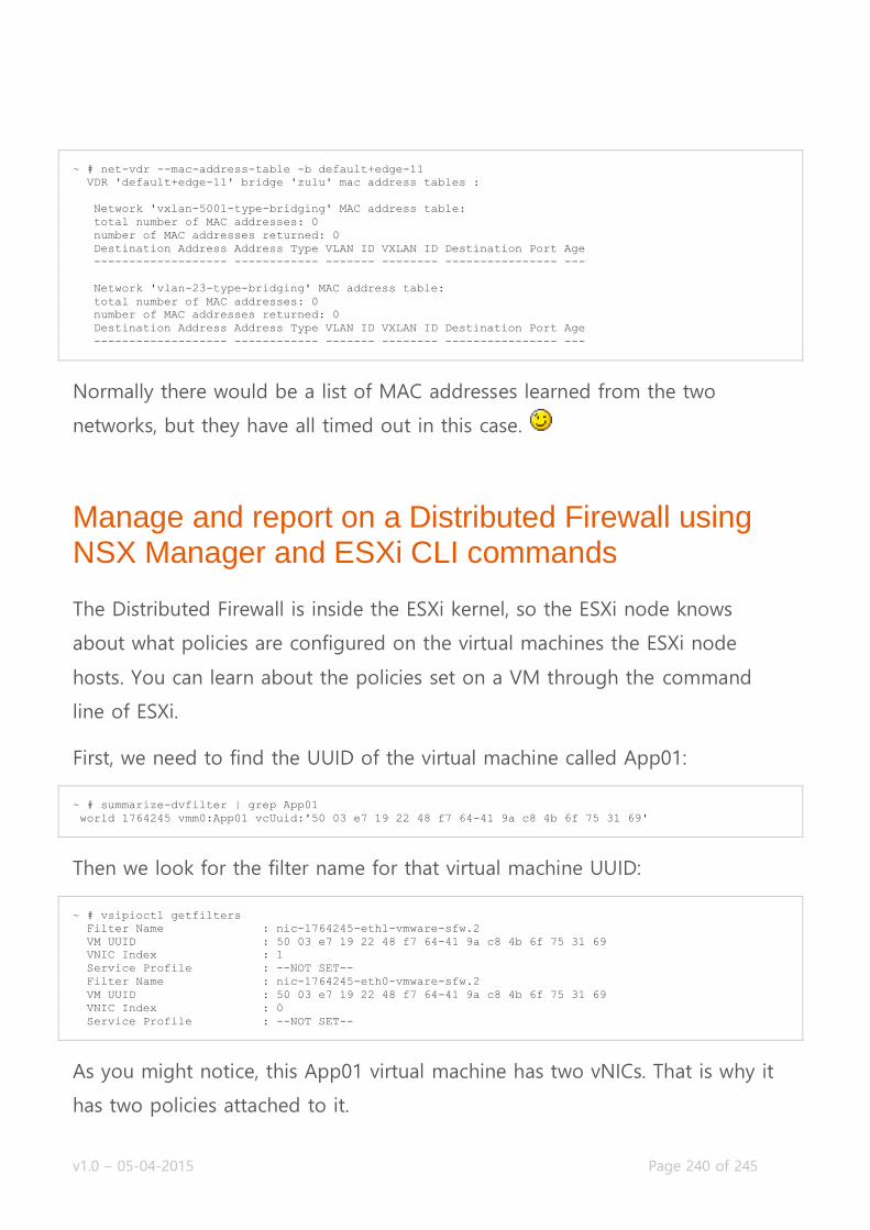
v1.0 – 05-04-2015 Page 240 of 245
~ # net-vdr --mac-address-table -b default+edge-11
VDR 'default+edge-11' bridge 'zulu' mac address tables :
Network 'vxlan-5001-type-bridging' MAC address table:
total number of MAC addresses: 0
number of MAC addresses returned: 0
Destination Address Address Type VLAN ID VXLAN ID Destination Port Age
------------------- ------------ ------- -------- ---------------- ---
Network 'vlan-23-type-bridging' MAC address table:
total number of MAC addresses: 0
number of MAC addresses returned: 0
Destination Address Address Type VLAN ID VXLAN ID Destination Port Age
------------------- ------------ ------- -------- ---------------- ---
Normally there would be a list of MAC addresses learned from the two
networks, but they have all timed out in this case.
Manage and report on a Distributed Firewall using NSX Manager and ESXi CLI commands
The Distributed Firewall is inside the ESXi kernel, so the ESXi node knows
about what policies are configured on the virtual machines the ESXi node
hosts. You can learn about the policies set on a VM through the command
line of ESXi.
First, we need to find the UUID of the virtual machine called App01:
~ # summarize-dvfilter | grep App01
world 1764245 vmm0:App01 vcUuid:'50 03 e7 19 22 48 f7 64-41 9a c8 4b 6f 75 31 69'
Then we look for the filter name for that virtual machine UUID:
~ # vsipioctl getfilters
Filter Name : nic-1764245-eth1-vmware-sfw.2
VM UUID : 50 03 e7 19 22 48 f7 64-41 9a c8 4b 6f 75 31 69
VNIC Index : 1
Service Profile : --NOT SET--
Filter Name : nic-1764245-eth0-vmware-sfw.2
VM UUID : 50 03 e7 19 22 48 f7 64-41 9a c8 4b 6f 75 31 69
VNIC Index : 0
Service Profile : --NOT SET--
As you might notice, this App01 virtual machine has two vNICs. That is why it
has two policies attached to it.
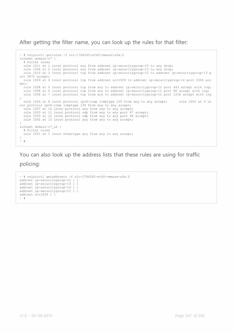
v1.0 – 05-04-2015 Page 241 of 245
After getting the filter name, you can look up the rules for that filter:
~ # vsipioctl getrules -f nic-1764245-eth0-vmware-sfw.2
ruleset domain-c7 {
# Filter rules
rule 1011 at 1 inout protocol any from addrset ip-securitygroup-15 to any drop;
rule 1006 at 2 inout protocol any from addrset ip-securitygroup-15 to any drop;
rule 1010 at 3 inout protocol tcp from addrset ip-securitygroup-12 to addrset ip-securitygroup-13 p
ort 5672 accept;
rule 1009 at 4 inout protocol tcp from addrset src1009 to addrset ip-securitygroup-14 port 3306 acc
ept;
rule 1008 at 5 inout protocol tcp from any to addrset ip-securitygroup-12 port 443 accept with log;
rule 1008 at 6 inout protocol tcp from any to addrset ip-securitygroup-12 port 80 accept with log;
rule 1008 at 7 inout protocol tcp from any to addrset ip-securitygroup-12 port 1234 accept with log
;
rule 1004 at 8 inout protocol ipv6-icmp icmptype 135 from any to any accept; rule 1004 at 9 in
out protocol ipv6-icmp icmptype 136 from any to any accept;
rule 1007 at 10 inout protocol any from any to any accept;
rule 1003 at 11 inout protocol udp from any to any port 67 accept;
rule 1003 at 12 inout protocol udp from any to any port 68 accept;
rule 1002 at 13 inout protocol any from any to any accept;
}
ruleset domain-c7_L2 {
# Filter rules
rule 1001 at 1 inout ethertype any from any to any accept;
}
~ #
You can also look up the address lists that these rules are using for traffic
policing:
~ # vsipioctl getaddrsets -f nic-1764245-eth0-vmware-sfw.2
addrset ip-securitygroup-12 { }
addrset ip-securitygroup-13 { }
addrset ip-securitygroup-14 { }
addrset ip-securitygroup-15 { }
addrset src1009 { }
~ #

v1.0 – 05-04-2015 Page 242 of 245
Manage and report on an Edge Services VPN-Plus device using NSX Edge and client OS CLI commands
Once the SSL-VPN feature on a NSX Edge has been configured, you can use
the command line of the NSX Edge to report the configuration and the
current usage of SSL-VPN users.
vShield-edge-6-0> show configuration sslvpn-plus
-----------------------------------------------------------------------
vShield Edge SSL VPN-Plus Config: {
"sslvpn" : {
"enable" : true,
"webResources" : [],
"users" : [
{
...snip...
}
],
"serverSettings" : {
"certificateId" : null,
"vmSize" : 1,
"cipherList" : [
"RC4-MD5"
],
"ips" : [
"10.192.123.153"
],
"port" : 443,
"ccu" : 100
},
...snip...
}
}
As you can see the configuration is presented in a JSON format and all
settings are included. Handy for easy safe-keeping. On to some operational
commands:
Checking to see whether the SSL VPN-Plus service is running.
vShield-edge-6-0> show service sslvpn-plus
-----------------------------------------------------------------------
vShield Edge SSL VPN-Plus Status:
SSL VPN-PLUS is running.
It is possible for the service to be configured through the GUI and possibly
not running due to a malfunction in the service that runs on the NSX Edge.
You’ll get a “connection refused” message if or when that happens. It’ll also

v1.0 – 05-04-2015 Page 243 of 245
return a “connection refused” when the SSL VPN-Plus service has not been
configured through the GUI.
If the service is configured and is accepting users, you can view what open
user sessions exist:
vShield-edge-6-0> show service sslvpn-plus sessions
3 martijn 0 Hr. 16 Min. 24 Sec
And for the last example, possibly the most important one, we’re going to
look at the current active SSL VPN tunnels on the NSX Edge:
vShield-edge-6-0> show service sslvpn-plus tunnels
Tunnel User Authenticated Tunnel Type Os-Type W-bytes R-bytes Uptime(s) Idle-time Virtual-ip : C
lient-ip(Port) Ref-count
191 martijn YES PHAT Win 0 0 1138 206 172.16.34.10 :
10.192.120.150(16090) 0000000001
As you can see each tunnel will be attached to an user, have uptime and
bandwidth counters and contains the virtual IP address that has been assigned
to the user from the IP Pool you have configured.
Manage and report on Load Balancers using NSX Edge CLI commands
Similar with the SSL VPN-Plus feature of the NSX ESG, the configuration for
load balancing has to be done from the GUI (or API), but information can be
requested from the command line. Also just like the SSL VPN-Plus feature, you
can request the running configuration:
vShield-edge-2-0> show configuration loadbalancer
-----------------------------------------------------------------------
vShield Edge Loadbalancer Config: {
"monitorService" : {
"logging" : {
"enable" : false,
"logLevel" : "info"
},
"enable" : true,
"healthMonitors" : [ ...snip...

v1.0 – 05-04-2015 Page 244 of 245
All configured settings are in the JSON output presented to you. Handy for
easy safe-keeping. Now for some operational command examples. Let’s start
with what is probably the most important one, getting the status of the virtual
servers:
vShield-edge-2-0> show service loadbalancer virtual myVirtualServer
-----------------------------------------------------------------------
Loadbalancer VirtualServer Statistics:
VIRTUAL myVirtualServer
| ADDRESS [10.192.123.154]:80
| SESSION (cur, max, total) = (0, 0, 0)
| RATE (cur, max, limit) = (0, 0, 0)
| BYTES in = (0), out = (0)
+->POOL Webfire-Pool
| LB METHOD ip-hash
| LB PROTOCOL L7
| Transparent disabled
| SESSION (cur, max, total) = (0, 0, 0)
| BYTES in = (0), out = (0)
+->POOL MEMBER: Webfire-Pool/web1, STATUS: UP
| | STATUS = UP, MONITOR STATUS = OK
| | SESSION (cur, max, total) = (11, 11, 253)
| | BYTES in = (2542), out = (2344)
+->POOL MEMBER: Webfire-Pool/web2, STATUS: DOWN
| | STATUS = UP, MONITOR STATUS = CRITICAL
| | SESSION (cur, max, total) = (0, 0, 0)
| | BYTES in = (0), out = (0)
The output is fairly technical, but it’s pretty readable. There is a tree for every
virtual server, listing the IP address and other settings first. Then it goes into
the server pool attached to the virtual server, displays the global settings of
that pool and then drills into the real servers configured in that pool. All
objects in the output have a status field, which shows you whether the service
is online. As you can see from this example, my web1 server is working
correctly and receiving incoming connections, while the web2 server is down
and not receiving any connections.
You can also omit the virtual server name in the command to get an overview
of all operational virtual servers.
If you’re just looking of the status of a specific server pool, you can use this
command:
vShield-edge-2-0> show service loadbalancer pool [pool_name]
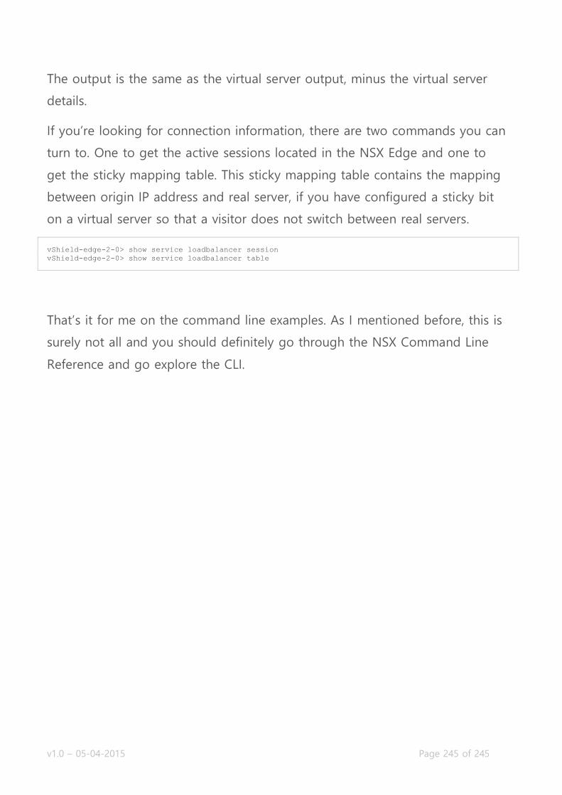
v1.0 – 05-04-2015 Page 245 of 245
The output is the same as the virtual server output, minus the virtual server
details.
If you’re looking for connection information, there are two commands you can
turn to. One to get the active sessions located in the NSX Edge and one to
get the sticky mapping table. This sticky mapping table contains the mapping
between origin IP address and real server, if you have configured a sticky bit
on a virtual server so that a visitor does not switch between real servers.
vShield-edge-2-0> show service loadbalancer session
vShield-edge-2-0> show service loadbalancer table
That’s it for me on the command line examples. As I mentioned before, this is
surely not all and you should definitely go through the NSX Command Line
Reference and go explore the CLI.