theremino cnc - v5.1 instructions · display settings re-size the two halves of the main window the...
TRANSCRIPT
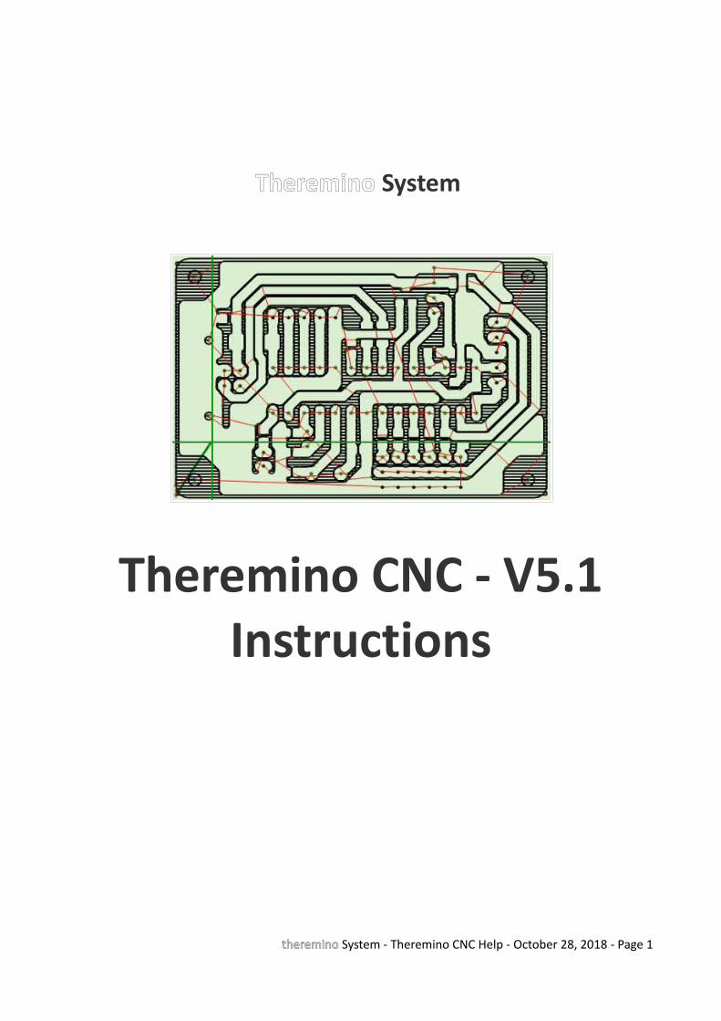
Theremino System
Theremino CNC - V5.1Instructions
theremino System - Theremino CNC Help - October 28, 2018 - Page 1

Table of ContentsTheremino CNC.....................................................................................................................................4
Start without reading the instructions............................................................................................5What if Theremino CNC does not start............................................................................................6
Display Settings.....................................................................................................................................7
Re-size the two halves of the main window....................................................................................7Hardware controls...........................................................................................................................7Choose colors...................................................................................................................................8The DPI setting in the Windows screen...........................................................................................8
GCode...................................................................................................................................................9
Gcode panel.....................................................................................................................................9GCode context menu.....................................................................................................................10Modify the GCode..........................................................................................................................11
Toolpath..............................................................................................................................................12
Toolpath panel...............................................................................................................................12Keyboard Controls (manual JOG)...................................................................................................13Mouse Controls..............................................................................................................................13Touchpad Controls.........................................................................................................................14Gamepad Controls.........................................................................................................................15Toolpath Views...............................................................................................................................16Initial reset.....................................................................................................................................17
Controls and Settings..........................................................................................................................18
Control Panel..................................................................................................................................18Motor Panel (left side)...................................................................................................................19Motor Panel (right).......................................................................................................................20Insert manually a coordinate.........................................................................................................21Make small corrections during processing....................................................................................21Axes A and B...................................................................................................................................22Calibration Panel............................................................................................................................23Tuning of calibration parameters...................................................................................................24The application Menu....................................................................................................................25The options Menu..........................................................................................................................26Tool Bar..........................................................................................................................................27Status Bar.......................................................................................................................................27
Motor settings in Theremino HAL......................................................................................................28
Adjusting values in the numerical boxes............................................................................................29
Multiple applications .........................................................................................................................30
Tips for less obvious functions...........................................................................................................31
theremino System - Theremino CNC Help - October 28, 2018 - Page 2
Appendix 1 - Machining speed...........................................................................................................32
Appendix 2 - The calculation of the trajectory...................................................................................33
Appendix 3 - Processing times............................................................................................................34
Appendix 4 - Implemented Functions................................................................................................35
Appendix 5 - Not Implemented Functions.........................................................................................37
Appendix 6 - The circular interpolations G02 and G03......................................................................38
Appendix 7 - HOME Controls (G28 and following).............................................................................39
Appendix 8 - Theremino CNC Adapter...............................................................................................40
Appendix 9 - Input / Output Slots......................................................................................................42
Master Module InOut PIN..............................................................................................................43Output signals................................................................................................................................44Input signals...................................................................................................................................45Wiring diagrams for all ON-OFF inputs..........................................................................................46
Appendix 10 - Rules for electrical connections..................................................................................47
Appendix 11 - opto-couplers..............................................................................................................48
Appendix 12 - Motor driver connections...........................................................................................49
Appendix 13 - The “Stepper Sound”...................................................................................................50
Appendix 14 - Double coordinates.....................................................................................................51
Appendix 15 - Settings to zero............................................................................................................52
Appendix 16 - The probes...................................................................................................................53
Appendix 17 - Interpolation in 5 dimensions vectors.........................................................................54
Appendix 18 - Control over control....................................................................................................55
Appendix 19 - Asynchronous operation.............................................................................................56
Appendix 20 - Accuracy of the forward speed...................................................................................57
Appendix 21 - Gcode generation for Theremino CNC........................................................................58
Appendix 22 - PCB built with Eagle and Fast Gcode...........................................................................59
Appendix 23 - 3D Printers...................................................................................................................61
Appendix 24 - Temperature sensors...................................................................................................62
Appendix 25 - Temperature tables.....................................................................................................63
Examples of temperature tables....................................................................................................64
theremino System - Theremino CNC Help - October 28, 2018 - Page 3
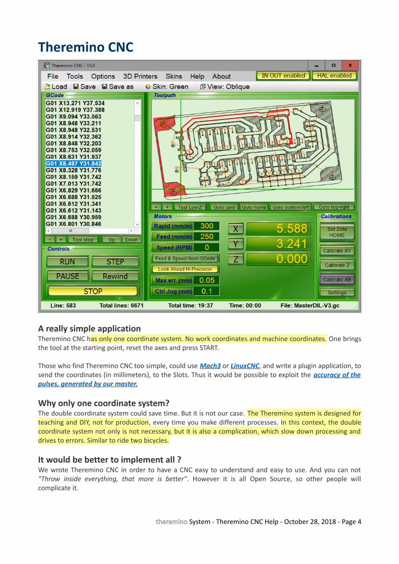
Theremino CNC
A really simple applicationTheremino CNC has only one coordinate system. No work coordinates and machine coordinates. One bringsthe tool at the starting point, reset the axes and press START.
Those who find Theremino CNC too simple, could use Mach3 or LinuxCNC, and write a plugin application, tosend the coordinates (in millimeters), to the Slots. Thus it would be possible to exploit the accuracy o f thepulses , generated by our master.
Why only one coordinate system?The double coordinate system could save time. But it is not our case. The Theremino system is designed forteaching and DIY, not for production, every time you make different processes. In this context, the doublecoordinate system not only is not necessary, but it is also a complication, which slow down processing anddrives to errors. Similar to ride two bicycles.
It would be better to implement all ?We wrote Theremino CNC in order to have a CNC easy to understand and easy to use. And you can not"Throw inside everything, that more is better". However it is all Open Source, so other people willcomplicate it.
theremino System - Theremino CNC Help - October 28, 2018 - Page 4

Start without reading the instructions
Check the parameters of the motorsThe main conditions are that the value of "Rapid" must not be greater than the "Maximum speed" of theslowest motor and the settings "Max acc." and "Steps per mm" of all motors must be adjusted, tested andoptimized. Also the Slot numbers have to match.
If the motors are not well regulated, as explained in the "Motor setting in the HAL", we advise to do onlybrief tests, without tools, with the tip held high "to eat air" and standing ready to press the START buttonagain, or the SPACE bar.
Load a GCodeTheremino CNC reads all extensions: .gc, .tap, .nc, .ncc, .dnc, .iso, and also .txt If the loading is done without error messages, you can start working immediately. Otherwise you have tocontrol codes "G" and "M" indicated and find a way to get rid of them. Or you can program the CAM not touse them (configure the post-processor). In all the cases, but especially when running GCode made byothers, it is good rule holding the Z axis very high and "work in air", until you are definitely sure that thetool path is right.
Move the tool at the start pointDeciding the starting point (zero processing) is a controversial practice. Some people consider to be zero,the leftmost and bottom position the machine can reach, when it hits the limit switches. Then prepare allGCode, with distances far from zero, so as to working, approximately in half range. And finally, fixing thework-piece, where the GCode will go to work. This way to reset is inaccurate and dangerous. Just wrongcalculations, or wrong position, can break the tool or scratch the work-piece. What is more, you can notmake more pieces, in different positions, using the same GCode.
It is better establishing zero point related to the work-piece (not related to machine) and "reset" all GCode.Thus, the zero values of GCode should indicate the point in the lower left of the work piece, not the zero ofthe machine. All GCode that are used, should follow this rule, you have to trust that the GCode. Possiblypass it all with the "Translate to zero" of the "Tools" menu.
Reset axesAfter the piece has been fastened and the tool tip taken manually exactly in the work-piece zero, press thezero axis. It is also possible to adjust a single coordinate, and then reset it (this is often done on the verticalaxis Z). The alignment with the machine remains valid, even after turning off the machine and PC. If theposition of the work-piece remains the same, you can interrupt the machining, and continue the next day. Itis not necessary to repeat the zeroing at every start-up.
StartPress START and immediately press it again to stop. This way you do a short test. If you feel somethingstrange (eg spindle motor that does not start), stop and check all the settings.
Starting again with START and be prepared to press it again, until you are sure, that the processing proceedsregularly.
theremino System - Theremino CNC Help - October 28, 2018 - Page 5
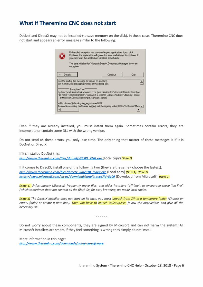
What if Theremino CNC does not start
DotNet and DirectX may not be installed (to save memory on the disk). In these cases Theremino CNC doesnot start and appears an error message similar to the following:
Even if they are already installed, you must install them again. Sometimes contain errors, they areincomplete or contain some DLL with the wrong version.
Do not send us these errors, you only lose time. The only thing that matter of these messages is if it isDotNet or DirectX.
If it's installed DotNet this: http://www.theremino.com/files/dotnetfx35SP1_ENG.exe (Local copy) (Note 1)
If it comes to DirectX, install one of the following two (they are the same - choose the fastest):http://www.theremino.com/files/directx_Jun2010_redist.exe (Local copy) (Note 1) (Note 2)https://www.microsoft.com/en-us/download/details.aspx?id=8109 (Download from Microsoft) (Note 2)
(Note 1) Unfortunately Microsoft frequently move files, and hides installers "off-line", to encourage those "on-line"(which sometimes does not contain all the files). So, for easy browsing, we made local copies.
(Note 2) The DirectX installer does not start on its own. you must unpack from ZIP in a temporary folder (Choose anempty folder or create a new one). Then you have to launch DxSetup.exe, follow the instructions and give all thenecessary OK.
- - - - - -
Do not worry about these components, they are signed by Microsoft and can not harm the system. AllMicrosoft installers are smart, if they feel something is wrong they simply do not install.
More information in this page:http://www.theremino.com/downloads/notes-on-software
theremino System - Theremino CNC Help - October 28, 2018 - Page 6
Display Settings
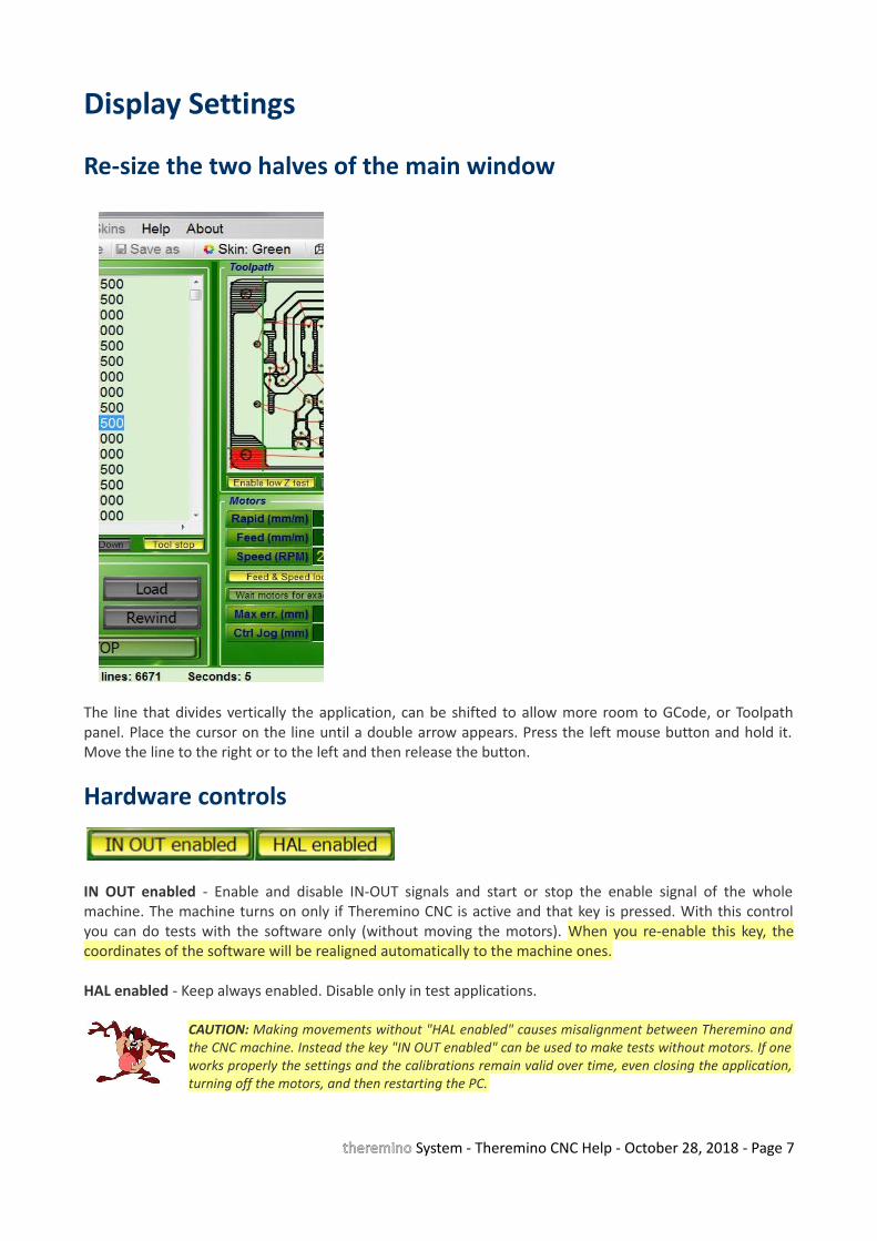
Re-size the two halves of the main window
The line that divides vertically the application, can be shifted to allow more room to GCode, or Toolpathpanel. Place the cursor on the line until a double arrow appears. Press the left mouse button and hold it.Move the line to the right or to the left and then release the button.
Hardware controls
IN OUT enabled - Enable and disable IN-OUT signals and start or stop the enable signal of the wholemachine. The machine turns on only if Theremino CNC is active and that key is pressed. With this controlyou can do tests with the software only (without moving the motors). When you re-enable this key, thecoordinates of the software will be realigned automatically to the machine ones.
HAL enabled - Keep always enabled. Disable only in test applications.
CAUTION: Making movements without "HAL enabled" causes misalignment between Theremino andthe CNC machine. Instead the key "IN OUT enabled" can be used to make tests without motors. If oneworks properly the settings and the calibrations remain valid over time, even closing the application,turning off the motors, and then restarting the PC.
theremino System - Theremino CNC Help - October 28, 2018 - Page 7
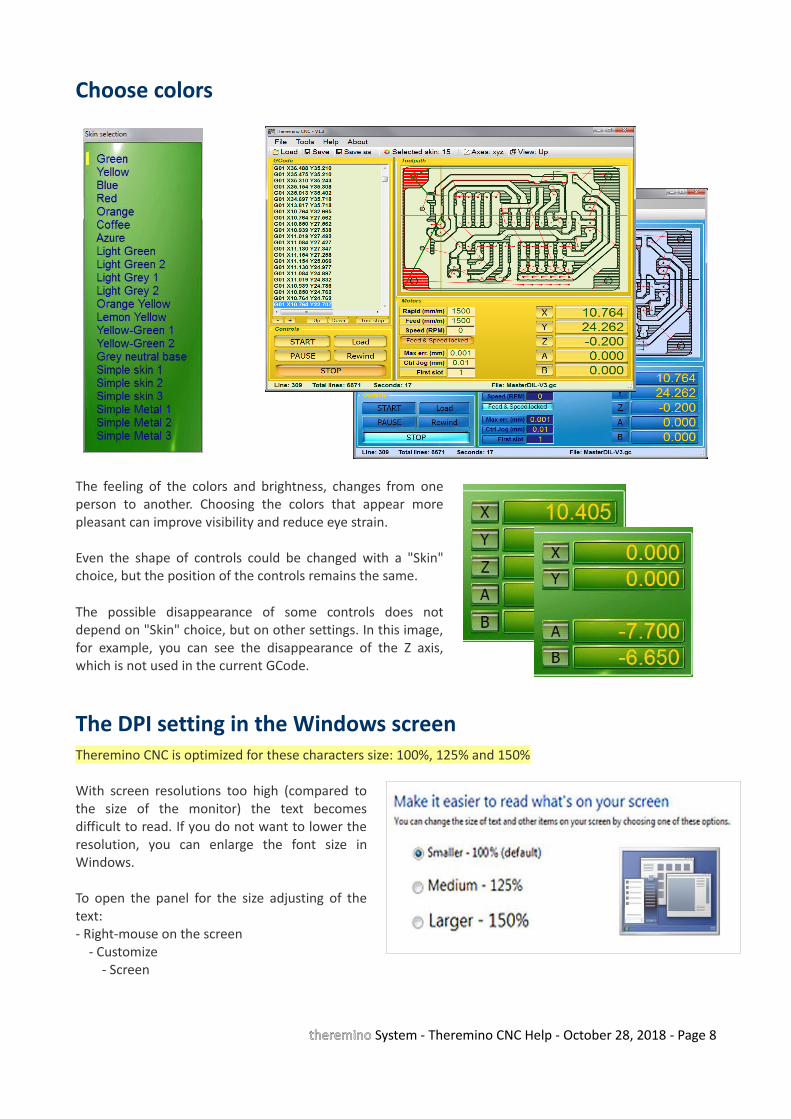
Choose colors
The feeling of the colors and brightness, changes from oneperson to another. Choosing the colors that appear morepleasant can improve visibility and reduce eye strain.
Even the shape of controls could be changed with a "Skin"choice, but the position of the controls remains the same.
The possible disappearance of some controls does notdepend on "Skin" choice, but on other settings. In this image,for example, you can see the disappearance of the Z axis,which is not used in the current GCode.
The DPI setting in the Windows screenTheremino CNC is optimized for these characters size: 100%, 125% and 150%
With screen resolutions too high (compared tothe size of the monitor) the text becomesdifficult to read. If you do not want to lower theresolution, you can enlarge the font size inWindows.
To open the panel for the size adjusting of thetext:- Right-mouse on the screen - Customize - Screen
theremino System - Theremino CNC Help - October 28, 2018 - Page 8
GCode
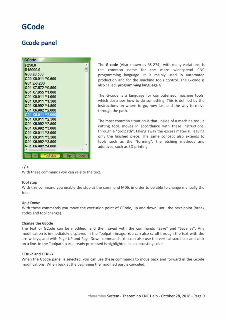
Gcode panel
The G-code (Also known as RS-274), with many variations, isthe common name for the more widespread CNCprogramming language. It is mainly used in automatedproduction and for the machine tools control. The G-code isalso called: programming language G.
The G-code is a language for computerized machine tools,which describes how to do something. This is defined by theinstructions on where to go, how fast and the way to movethrough the path.
The most common situation is that, inside of a machine tool, acutting tool, moves in accordance with these instructions,through a "toolpath", taking away the excess material, leavingonly the finished piece. The same concept also extends totools such as the "forming", the etching methods andadditives, such as 3D printing.
- / +With these commands you can re-size the text.
Tool stop With this command you enable the stop at the command M06, in order to be able to change manually thetool.
Up / DownWith these commands you move the execution point of GCode, up and down, until the next point (breakcodes and tool change).
Change the GcodeThe text of GCode can be modified, and then saved with the commands "Save" and "Save as". Anymodification is immediately displayed in the Toolpath image. You can also scroll through the text with thearrow keys, and with Page UP and Page Down commands. You can also use the vertical scroll bar and clickon a line. In the Toolpath part already processed is highlighted in a contrasting color.
CTRL-Z and CTRL-YWhen the Gcode panel is selected, you can use these commands to move back and forward in the Gcodemodifications. When back at the beginning the modified part is canceled.
theremino System - Theremino CNC Help - October 28, 2018 - Page 9
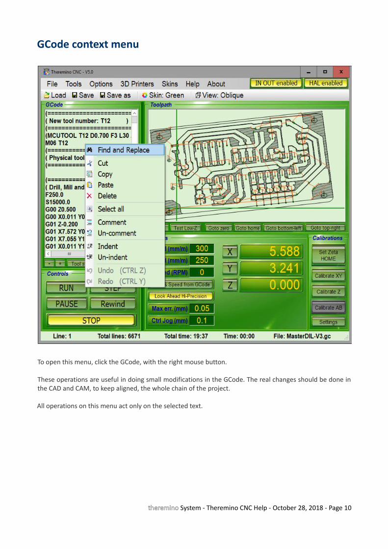
GCode context menu
To open this menu, click the GCode, with the right mouse button.
These operations are useful in doing small modifications in the GCode. The real changes should be done inthe CAD and CAM, to keep aligned, the whole chain of the project.
All operations on this menu act only on the selected text.
theremino System - Theremino CNC Help - October 28, 2018 - Page 10

Modify the GCode
Theremino CNC is a simple application, but has advanced commands (Find, Replace, Convert, Rotate,Translate, Normalize). With other CNC without these operations, you must use the "rotated work-piececoordinate system" or other methods, which involve the exchange of the axes with the resulting confusion.(eg the Zero X acting on the Y axis).
These commands are used to find text, and replace it if necessary. To open this panel, select "Find andreplace" in the menu on the previous page.
The operations of this menu, are performedthroughout the GCode, and not only on the area of Gcode selected.
There are operations useful to adjust the GCode,but it would be better to make them in the CAD andCAM, to keep “aligned” the whole chain of theproject.
Reset GCodeAll GCode should be reset in order to avoid the processing of the GCode “some where”.
But some GCode does not respond to reset command, even with the "Translate to zero", because they arewritten in a way doubly evil, with a displacement which plans to place the piece, roughly half machine. Buteven with some coordinates which are zero, leading the tip to slam, bottom left, against the limit switchesof the machine, and lowering the tool until it touches the part.
To clear the GCode not able to be reset, you must manually delete (carefully) all the lines, which lead thecoordinates to zero (usually at the beginning and at the end). Finally you use "Translate to zero" and checkin the Toolpath, that zeroing is correct. If you make a mistake use "Undo" and try again.
theremino System - Theremino CNC Help - October 28, 2018 - Page 11
Toolpath
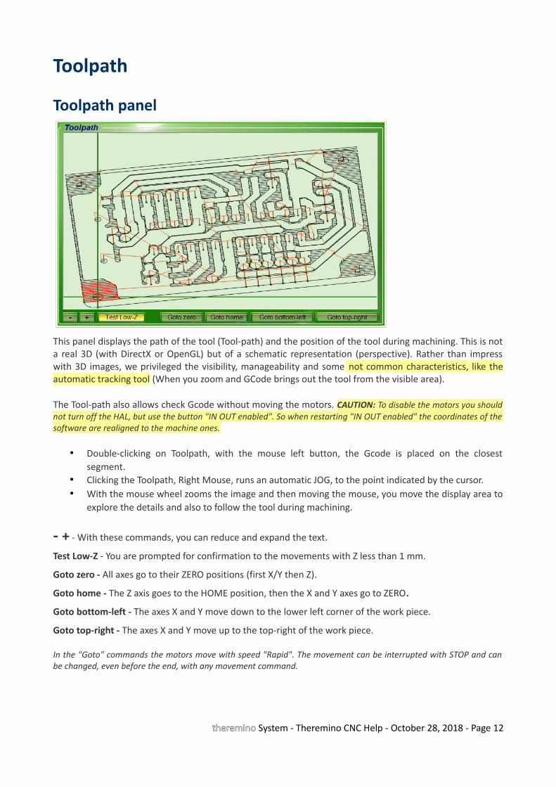
Toolpath panel
This panel displays the path of the tool (Tool-path) and the position of the tool during machining. This is nota real 3D (with DirectX or OpenGL) but of a schematic representation (perspective). Rather than impresswith 3D images, we privileged the visibility, manageability and some not common characteristics, like theautomatic tracking tool (When you zoom and GCode brings out the tool from the visible area).
The Tool-path also allows check Gcode without moving the motors. CAUTION: To disable the motors you shouldnot turn off the HAL, but use the button "IN OUT enabled". So when restarting "IN OUT enabled" the coordinates of thesoftware are realigned to the machine ones.
• Double-clicking on Toolpath, with the mouse left button, the Gcode is placed on the closestsegment.
• Clicking the Toolpath, Right Mouse, runs an automatic JOG, to the point indicated by the cursor.• With the mouse wheel zooms the image and then moving the mouse, you move the display area to
explore the details and also to follow the tool during machining.
- + - With these commands, you can reduce and expand the text.
Test Low-Z - You are prompted for confirmation to the movements with Z less than 1 mm.
Goto zero - All axes go to their ZERO positions (first X/Y then Z).
Goto home - The Z axis goes to the HOME position, then the X and Y axes go to ZERO.
Goto bottom-left - The axes X and Y move down to the lower left corner of the work piece.
Goto top-right - The axes X and Y move up to the top-right of the work piece.
In the "Goto" commands the motors move with speed "Rapid". The movement can be interrupted with STOP and canbe changed, even before the end, with any movement command.
theremino System - Theremino CNC Help - October 28, 2018 - Page 12
Keyboard Controls (manual JOG)
RIGHT and LEFT Arrows = Jog axis XUP and DOWN Arrows = Jog axis YPAGE-UP and PAGE-DOWN = Jog axis ZLetters Z and X = Jog axis Z <-- For keyboards without Page Up / DownLetters A and S = Jog axis ALetters B and N = Jog axis BSHIFT + previous keys = Jog with speed “Jog speed SHIFT”CTRL + previous keys = Individual steps, specified in the "Ctrl Jog (mm)"ALT + previous keys = Thousandths of a millimeter, with auto-repeatF8 = RUNF5 = STEP
Arrows and letters used alone move with "Jog speed normal" rate (see the Options Menu)While holding down SHIFT, the speed is determined by "Jog Speed SHIFT" (see the Options Menu)Jog and SHIFT + Jog movements also act on several axes, those with CTRL and ALT only one axis at a time.
If the GCode panel is active, then the keyboard acts on GCode.To enable the Jog instead of GCode, you click with the mouse in the frame of the Toolpath.
Prerequisite for the "JOG" is that "Rapid" is not greater than the slowest motor (settings"Max speed" motor HAL) and the settings of the motors (HAL) are correct.
Mouse Controls
Click on GCodeSelect the line to be executed and the part already performed is highlighted in the graphics window.
Double click the left mouse button on the Toolpath The Gcode is placed on the closest segment.
Click on the Toolpath with right mouse buttonJog is performed automatically to the point indicated by the cursor.The axes which move depend on the type of view (perspective) currently selected and are always only two(XY, XZ, YZ, AB, AZ, BZ).Be careful that the parallax can sometimes deceive (Z may be higher or lower than it seems).
Mouse wheel Magnification of the graphic and, moving the mouse, shifting the displayed area.
Prerequisite for the movements, is that "Rapid" is not greater than the motor slower(settings "Max speed" motor HAL) and the settings of the engines (HAL), are correct.
theremino System - Theremino CNC Help - October 28, 2018 - Page 13

Touchpad Controls
The right side of the pad, which simulates a mouse wheel,can act on the Toolpath zoom.
On some notebooks, especially with XP, this simulationdoes not work well (works only on the text of GCode andnot on the graphics window).
In these cases go to:Control panel Mouse Hardware Property Driver Update Driver
And finally, use the search and automatic installation of the driver: "Allow the connection to Windows tosearch for software"
If you can not enable zooming on the pad, you can use the buttons “-” e “+” situated under the Toolpathwindow.
Adjust the zoom speed with the touchpad
Open: Control panel Mouse Device settings Settings Virtual Scrolling Scrolling long paths Sliding speed
Finally adjust the slider. It is advisable to adjust it at about halfway.
theremino System - Theremino CNC Help - October 28, 2018 - Page 14
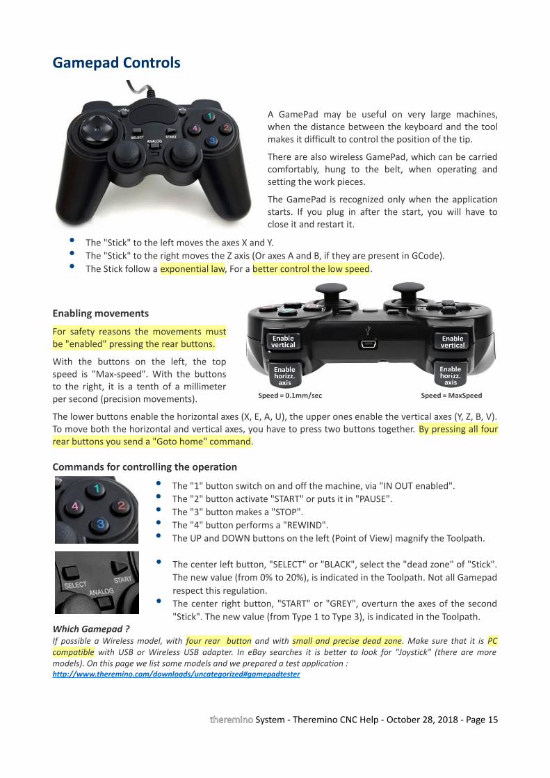
Gamepad Controls
A GamePad may be useful on very large machines,when the distance between the keyboard and the toolmakes it difficult to control the position of the tip.
There are also wireless GamePad, which can be carriedcomfortably, hung to the belt, when operating andsetting the work pieces.
The GamePad is recognized only when the applicationstarts. If you plug in after the start, you will have toclose it and restart it.
• The "Stick" to the left moves the axes X and Y.• The "Stick" to the right moves the Z axis (Or axes A and B, if they are present in GCode).• The Stick follow a exponential law, For a better control the low speed.
Enabling movements
For safety reasons the movements mustbe "enabled" pressing the rear buttons.
With the buttons on the left, the topspeed is "Max-speed". With the buttonsto the right, it is a tenth of a millimeterper second (precision movements).
The lower buttons enable the horizontal axes (X, E, A, U), the upper ones enable the vertical axes (Y, Z, B, V).To move both the horizontal and vertical axes, you have to press two buttons together. By pressing all fourrear buttons you send a "Goto home" command.
Commands for controlling the operation
• The "1" button switch on and off the machine, via "IN OUT enabled".• The "2" button activate "START" or puts it in "PAUSE".• The "3" button makes a "STOP".• The "4" button performs a "REWIND".• The UP and DOWN buttons on the left (Point of View) magnify the Toolpath.
• The center left button, "SELECT" or "BLACK", select the "dead zone" of "Stick".The new value (from 0% to 20%), is indicated in the Toolpath. Not all Gamepadrespect this regulation.
• The center right button, "START" or "GREY", overturn the axes of the second"Stick". The new value (from Type 1 to Type 3), is indicated in the Toolpath.
Which Gamepad ?If possible a Wireless model, with four rear button and with small and precise dead zone. Make sure that it is PCcompatible with USB or Wireless USB adapter. In eBay searches it is better to look for "Joystick" (there are moremodels). On this page we list some models and we prepared a test application :http://www.theremino.com/downloads/uncategorized#gamepadtester
theremino System - Theremino CNC Help - October 28, 2018 - Page 15

Toolpath Views
Up - Top View Front - Front View Side - Side View
Frontal - From Above Isometric - 3D isometric Oblique - oblique 3D
With this menu, you can choose the type of display.
If GCode includes axes A and B then three other views will appear (not shownhere) :
• AB_Up• AB_Isometric• AB_Oblique
- - - - - - -
Because the toolpath is not a true 3D?
Short answer: Because the 3D should be done in CAD, not in CAM and let alone in the CNC.
Long answer: Even before publishing the first version, many people asked this question. So we carefully consideredthe pros and cons. Definitely a good thing would be the visual impact. But we are not here for “show” and we are notinterested in selling. Rather we want to see clearly the path during processing and that the software would be validalso for educational purposes. So easy to use and easy to understand and with all trigonometric functions clearlywritten without calling DirectX or OpenGL.
These are not justifications. When the 3D is to be used we know how to, here are some of our achievements:http://www.theremino.com/downloads/uncategorized#3D http://www.fastvr.com/web/it/about_Gallery.htmhttp://www.fastvr.com/web/it/downloads_Demos.htmwww.spray3d.it/new
theremino System - Theremino CNC Help - October 28, 2018 - Page 16
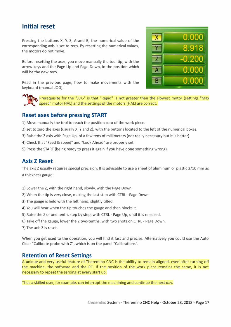
Initial reset
Pressing the buttons X, Y, Z, A and B, the numerical value of thecorresponding axis is set to zero. By resetting the numerical values,the motors do not move.
Before resetting the axes, you move manually the tool tip, with thearrow keys and the Page Up and Page Down, in the position whichwill be the new zero.
Read in the previous page, how to make movements with thekeyboard (manual JOG).
Prerequisite for the "JOG" is that "Rapid" is not greater than the slowest motor (settings "Maxspeed" motor HAL) and the settings of the motors (HAL) are correct.
Reset axes before pressing START1) Move manually the tool to reach the position zero of the work piece.
2) set to zero the axes (usually X, Y and Z), with the buttons located to the left of the numerical boxes.
3) Raise the Z axis with Page Up, of a few tens of millimeters (not really necessary but it is better)
4) Check that "Feed & speed" and "Look Ahead" are properly set
5) Press the START (being ready to press it again if you have done something wrong)
Axis Z ResetThe axis Z usually requires special precision. It is advisable to use a sheet of aluminum or plastic 2/10 mm as
a thickness gauge:
1) Lower the Z, with the right hand, slowly, with the Page Down
2) When the tip is very close, making the last step with CTRL - Page Down.
3) The gauge is held with the left hand, slightly tilted.
4) You will hear when the tip touches the gauge and then blocks it.
5) Raise the Z of one tenth, step by step, with CTRL - Page Up, until it is released.
6) Take off the gauge, lower the Z two-tenths, with two shots on CTRL - Page Down.
7) The axis Z is reset.
When you get used to the operation, you will find it fast and precise. Alternatively you could use the AutoClear "Calibrate probe with Z", which is on the panel "Calibrations".
Retention of Reset SettingsA unique and very useful feature of Theremino CNC is the ability to remain aligned, even after turning offthe machine, the software and the PC. If the position of the work piece remains the same, it is notnecessary to repeat the zeroing at every start up.
Thus a skilled user, for example, can interrupt the machining and continue the next day.
theremino System - Theremino CNC Help - October 28, 2018 - Page 17
Controls and Settings
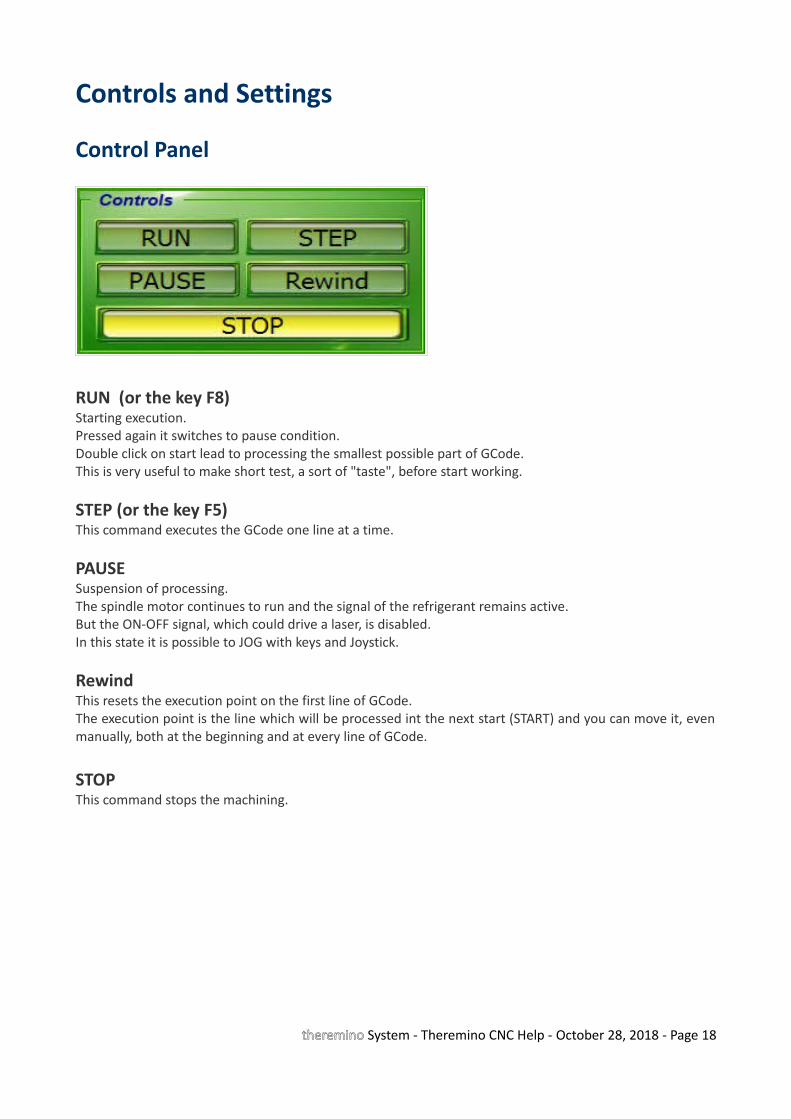
Control Panel
RUN (or the key F8)Starting execution.Pressed again it switches to pause condition.Double click on start lead to processing the smallest possible part of GCode. This is very useful to make short test, a sort of "taste", before start working.
STEP (or the key F5)This command executes the GCode one line at a time.
PAUSESuspension of processing. The spindle motor continues to run and the signal of the refrigerant remains active. But the ON-OFF signal, which could drive a laser, is disabled.In this state it is possible to JOG with keys and Joystick.
RewindThis resets the execution point on the first line of GCode.The execution point is the line which will be processed int the next start (START) and you can move it, evenmanually, both at the beginning and at every line of GCode.
STOPThis command stops the machining.
theremino System - Theremino CNC Help - October 28, 2018 - Page 18
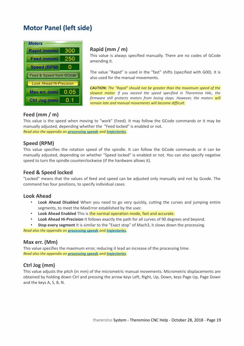
Motor Panel (left side)
Rapid (mm / m)This value is always specified manually. There are no codes of GCodeamending it.
The value "Rapid" is used in the "fast" shifts (specified with G00). It isalso used for the manual movements.
CAUTION: The "Rapid" should not be greater than the maximum speed of theslowest motor. If you exceed the speed specified in Theremino HAL, thefirmware still protects motors from losing steps. However, the motors willremain late and manual movements will become difficult.
Feed (mm / m)This value is the speed when moving to "work" (Feed). It may follow the GCode commands or it may bemanually adjusted, depending whether the "Feed locked" is enabled or not.Read also the appendix on processing speeds and trajectories.
Speed (RPM)This value specifies the rotation speed of the spindle. It can follow the GCode commands or it can bemanually adjusted, depending on whether "Speed locked" is enabled or not. You can also specify negativespeed to turn the spindle counterclockwise (if the hardware allows it).
Feed & Speed locked"Locked" means that the values of feed and speed can be adjusted only manually and not by Gcode. Thecommand has four positions, to specify individual cases.
Look Ahead• Look Ahead Disabled When you need to go very quickly, cutting the curves and jumping entire
segments, to meet the MaxError established by the user. • Look Ahead Enabled This is the normal operation mode, fast and accurate. • Look Ahead Hi-Precision It follows exactly the path for all curves of 90 degrees and beyond. • Stop every segment It is similar to the "Exact stop" of Mach3, it slows down the processing.
Read also the appendix on processing speeds and trajectories.
Max err. (Mm)This value specifies the maximum error, reducing it lead an increase of the processing time. Read also the appendix on processing speeds and trajectories.
Ctrl Jog (mm)This value adjusts the pitch (in mm) of the micrometric manual movements. Micrometric displacements areobtained by holding down Ctrl and pressing the arrow keys Left, Right, Up, Down, keys Page Up, Page Downand the keys A, S, B, N.
theremino System - Theremino CNC Help - October 28, 2018 - Page 19
Motor Panel (right)
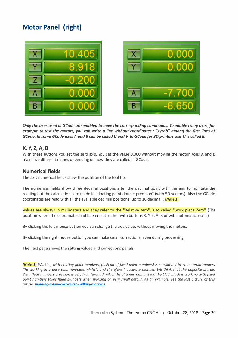
Only the axes used in GCode are enabled to have the corresponding commands. To enable every axes, forexample to test the motors, you can write a line without coordinates : "xyzab" among the first lines ofGCode. In some GCode axes A and B can be called U and V. In GCode for 3D printers axis U is called E.
X, Y, Z, A, BWith these buttons you set the zero axis. You set the value 0.000 without moving the motor. Axes A and Bmay have different names depending on how they are called in GCode.
Numerical fieldsThe axis numerical fields show the position of the tool tip.
The numerical fields show three decimal positions after the decimal point with the aim to facilitate thereading but the calculations are made in "floating point double precision" (with 5D vectors). Also the GCodecoordinates are read with all the available decimal positions (up to 16 decimal). (Note 1)
Values are always in millimeters and they refer to the "Relative zero", also called "work piece Zero" (Theposition where the coordinates had been reset, either with buttons X, Y, Z, A, B or with automatic resets)
By clicking the left mouse button you can change the axis value, without moving the motors.
By clicking the right mouse button you can make small corrections, even during processing.
The next page shows the setting values and corrections panels.
(Note 1) Working with floating point numbers, (instead of fixed point numbers) is considered by some programmerslike working in a uncertain, non-deterministic and therefore inaccurate manner. We think that the opposite is true.With float numbers precision is very high (around millionths of a micron). Instead the CNC which is working with fixedpoint numbers takes huge blunders when working on very small details. As an example, see the last picture of thisarticle: building-a-low-cost-micro-milling-machine
theremino System - Theremino CNC Help - October 28, 2018 - Page 20
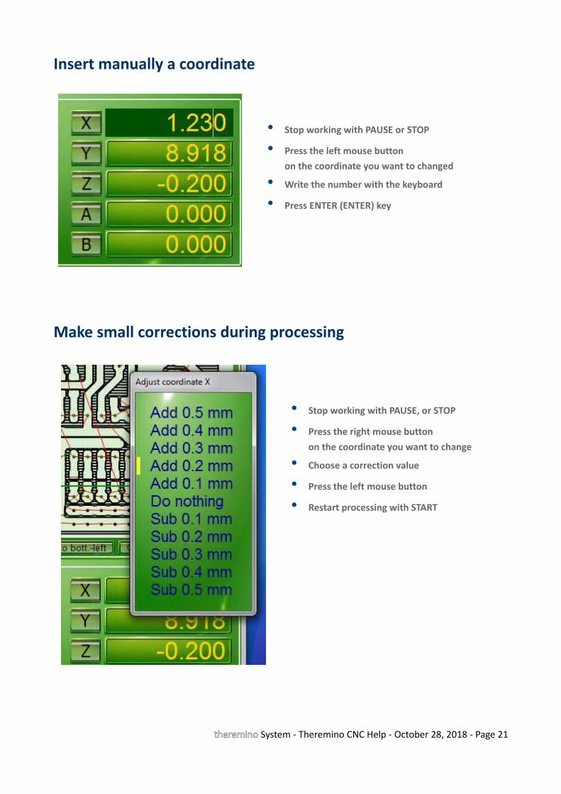
Insert manually a coordinate
• Stop working with PAUSE or STOP
• Press the left mouse button on the coordinate you want to changed
• Write the number with the keyboard
• Press ENTER (ENTER) key
Make small corrections during processing
• Stop working with PAUSE, or STOP
• Press the right mouse buttonon the coordinate you want to change
• Choose a correction value
• Press the left mouse button
• Restart processing with START
theremino System - Theremino CNC Help - October 28, 2018 - Page 21
Axes A and B
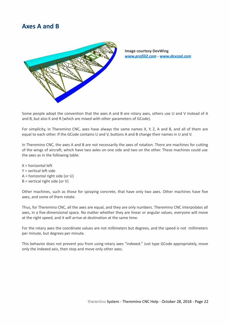
Image courtesy DevWingwww.profili2.com - www.devcad.com
Some people adopt the convention that the axes A and B are rotary axes, others use U and V instead of Aand B, but also K and R (which are mixed with other parameters of GCode).
For simplicity, in Theremino CNC, axes have always the same names X, Y, Z, A and B, and all of them areequal to each other. If the GCode contains U and V, buttons A and B change their names in U and V.
In Theremino CNC, the axes A and B are not necessarily the axes of rotation. There are machines for cuttingof the wings of aircraft, which have two axles on one side and two on the other. These machines could usethe axes as in the following table:
X = horizontal leftY = vertical left sideA = horizontal right side (or U)B = vertical right side (or V)
Other machines, such as those for spraying concrete, that have only two axes. Other machines have fiveaxes, and some of them rotate.
Thus, for Theremino CNC, all the axes are equal, and they are only numbers. Theremino CNC interpolates allaxes, in a five-dimensional space. No matter whether they are linear or angular values, everyone will moveat the right speed, and it will arrive at destination at the same time.
For the rotary axes the coordinate values are not millimeters but degrees, and the speed is not millimetersper minute, but degrees per minute.
This behavior does not prevent you from using rotary axes "indexed." Just type GCode appropriately, moveonly the indexed axis, then stop and move only other axes.
theremino System - Theremino CNC Help - October 28, 2018 - Page 22
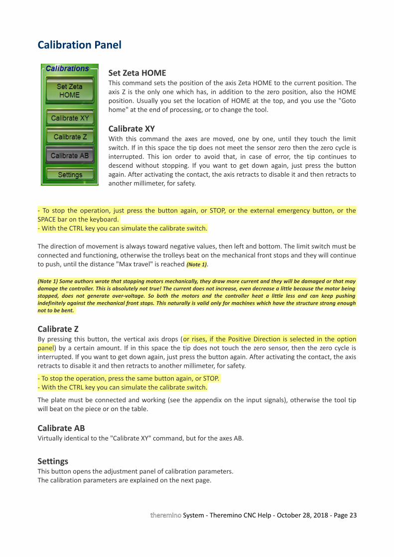
Calibration Panel
Set Zeta HOMEThis command sets the position of the axis Zeta HOME to the current position. Theaxis Z is the only one which has, in addition to the zero position, also the HOMEposition. Usually you set the location of HOME at the top, and you use the "Gotohome" at the end of processing, or to change the tool.
Calibrate XYWith this command the axes are moved, one by one, until they touch the limitswitch. If in this space the tip does not meet the sensor zero then the zero cycle isinterrupted. This ion order to avoid that, in case of error, the tip continues todescend without stopping. If you want to get down again, just press the buttonagain. After activating the contact, the axis retracts to disable it and then retracts toanother millimeter, for safety.
- To stop the operation, just press the button again, or STOP, or the external emergency button, or theSPACE bar on the keyboard. - With the CTRL key you can simulate the calibrate switch.
The direction of movement is always toward negative values, then left and bottom. The limit switch must beconnected and functioning, otherwise the trolleys beat on the mechanical front stops and they will continueto push, until the distance "Max travel" is reached (Note 1).
(Note 1) Some authors wrote that stopping motors mechanically, they draw more current and they will be damaged or that maydamage the controller. This is absolutely not true! The current does not increase, even decrease a little because the motor beingstopped, does not generate over-voltage. So both the motors and the controller heat a little less and can keep pushingindefinitely against the mechanical front stops. This naturally is valid only for machines which have the structure strong enoughnot to be bent.
Calibrate ZBy pressing this button, the vertical axis drops (or rises, if the Positive Direction is selected in the optionpanel) by a certain amount. If in this space the tip does not touch the zero sensor, then the zero cycle isinterrupted. If you want to get down again, just press the button again. After activating the contact, the axisretracts to disable it and then retracts to another millimeter, for safety.
- To stop the operation, press the same button again, or STOP. - With the CTRL key you can simulate the calibrate switch.
The plate must be connected and working (see the appendix on the input signals), otherwise the tool tipwill beat on the piece or on the table.
Calibrate ABVirtually identical to the "Calibrate XY" command, but for the axes AB.
SettingsThis button opens the adjustment panel of calibration parameters.The calibration parameters are explained on the next page.
theremino System - Theremino CNC Help - October 28, 2018 - Page 23
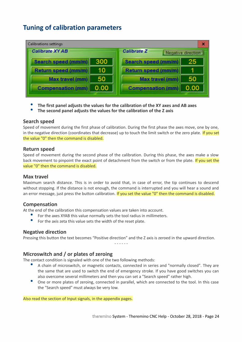
Tuning of calibration parameters
• The first panel adjusts the values for the calibration of the XY axes and AB axes• The second panel adjusts the values for the calibration of the Z axis
Search speedSpeed of movement during the first phase of calibration. During the first phase the axes move, one by one,in the negative direction (coordinates that decrease) up to touch the limit switch or the zero plate. If you setthe value "0" then the command is disabled.
Return speedSpeed of movement during the second phase of the calibration. During this phase, the axes make a slowback movement to pinpoint the exact point of detachment from the switch or from the plate. If you set thevalue "0" then the command is disabled.
Max travelMaximum search distance. This is in order to avoid that, in case of error, the tip continues to descendwithout stopping. If the distance is not enough, the command is interrupted and you will hear a sound andan error message, just press the button calibration. If you set the value "0" then the command is disabled.
CompensationAt the end of the calibration this compensation values are taken into account.
• For the axes XYAB this value normally sets the tool radius in millimeters.• For the axis zeta this value sets the width of the reset plate.
Negative directionPressing this button the text becomes “Positive direction” and the Z axis is zeroed in the upward direction.
- - - - - -
Microswitch and / or plates of zeroingThe contact condition is signaled with one of the two following methods:
• A chain of microswitch, or magnetic contacts, connected in series and "normally closed". They arethe same that are used to switch the end of emergency stroke. If you have good switches you canalso overcome several millimeters and then you can set a "Search speed" rather high.
• One or more plates of zeroing, connected in parallel, which are connected to the tool. In this casethe "Search speed" must always be very low.
Also read the section of Input signals, in the appendix pages.
theremino System - Theremino CNC Help - October 28, 2018 - Page 24
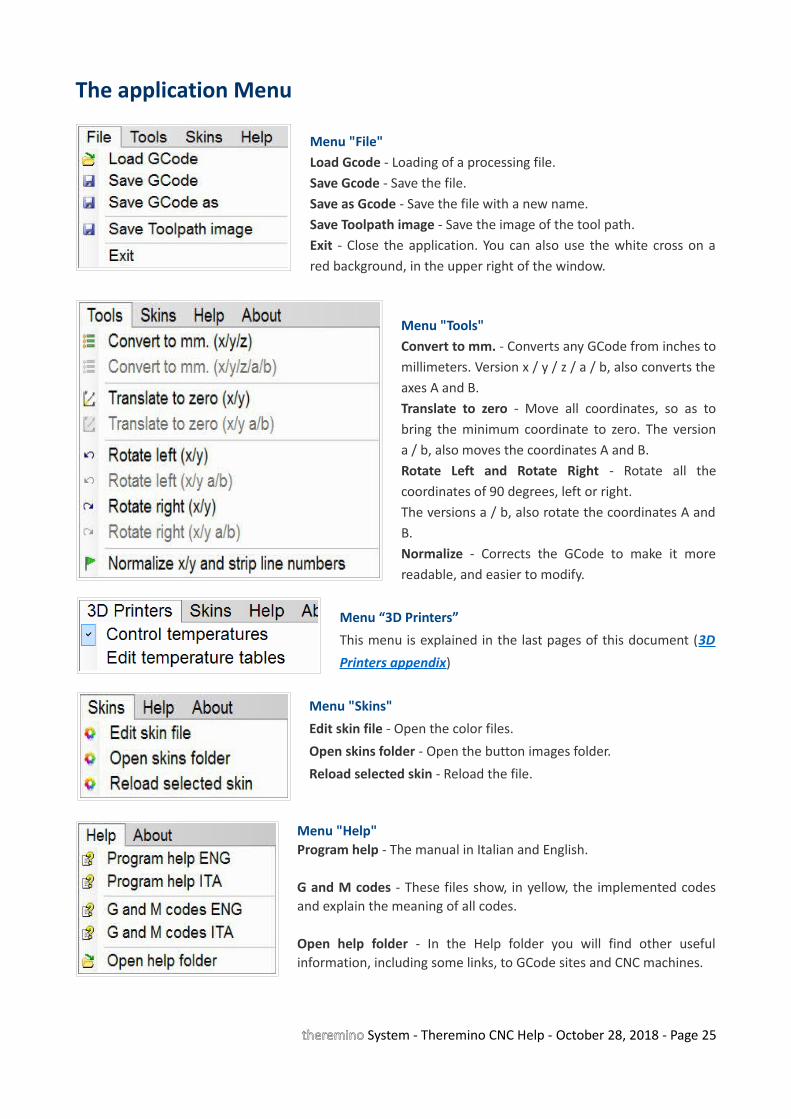
The application Menu
Menu "File"Load Gcode - Loading of a processing file.Save Gcode - Save the file.Save as Gcode - Save the file with a new name.Save Toolpath image - Save the image of the tool path.Exit - Close the application. You can also use the white cross on ared background, in the upper right of the window.
Menu "Tools"Convert to mm. - Converts any GCode from inches tomillimeters. Version x / y / z / a / b, also converts theaxes A and B.Translate to zero - Move all coordinates, so as tobring the minimum coordinate to zero. The versiona / b, also moves the coordinates A and B. Rotate Left and Rotate Right - Rotate all thecoordinates of 90 degrees, left or right.The versions a / b, also rotate the coordinates A andB. Normalize - Corrects the GCode to make it morereadable, and easier to modify.
Menu “3D Printers”
This menu is explained in the last pages of this document (3D
Printers appendix)
Menu "Skins"
Edit skin file - Open the color files.
Open skins folder - Open the button images folder.
Reload selected skin - Reload the file.
Menu "Help"Program help - The manual in Italian and English.
G and M codes - These files show, in yellow, the implemented codesand explain the meaning of all codes.
Open help folder - In the Help folder you will find other usefulinformation, including some links, to GCode sites and CNC machines.
theremino System - Theremino CNC Help - October 28, 2018 - Page 25

The options Menu (left part)
First SlotThis is the first slot to be used for the inputs and outputs. See the Appendix 9 - Input / OutputSlots.
Jog speed normalThis is the “Jog” moving speed, see the Keyboard Controls. The range is from 1% to 100% of the“Rapid” speed.
Jog speed with SHIFTThis is the “Jog + SHIFT” moving speed, see the Keyboard Controls. The range is from 1% to 100%of the “Rapid” speed.
Delay after spindle ONThis value is a pause time in seconds and fractions. The pause is applied each time the spindlemotor (Slot 11) and serves to allow time for slow motors to reach the working speed. Note thatevery time you switch to Rapid (G00), the spindle motor stops and then resuming machining thereis a new pause. If you want a different behavior you set this value to zero and specify pauses (G04)at the desired points of the GCode.
theremino System - Theremino CNC Help - October 28, 2018 - Page 26

The options Menu (right part)
Movement type• Normal movement - This mode of operation is suitable for classic "Cartesian" machines, ie
with the axes orthogonal to each other, and a motor for each axis.• CoreXY with motors A-B - This mode of operation is only suitable for machines with belts
connected in "CoreXY" mode, and only two motors called A-B. More information on thesemachines can be found on many websites, for example on this page.
Stop soundWith this button you can choose the sounds to be used as signal for the end of processing (whenthe Gcode is finished and the application goes into STOP mode).
Show real tip positionBy enabling this option the toolpath the cross-hairs and the axes numerical coordinates show theactual position of the engines. Then you can visually check the path failure. To see the actualposition of the motors the HAL must be active and connected to the Master. If you do not want tomove the motors you can switch off the driver power supply.
Under normal conditions the position requested by the software and the real one are very similarfor which the effect of this command is not very visible. But in some cases the motors are "leftbehind" and you can see significant differences between the location specified by GCode and thereal one. To avoid these path errors you have to increase the acceleration or reduce the maximumspeed in the HAL application (Max Speed no more than five or at most ten times Max Acc). It isalso important to reduce the segment max lenght in the Cam post-processor.
Compensate acceleration effectsThis option enables the compensation of the path errors, caused by low acceleration engines. Seethe Appendix 26 - Low accelerations compensation.
theremino System - Theremino CNC Help - October 28, 2018 - Page 27
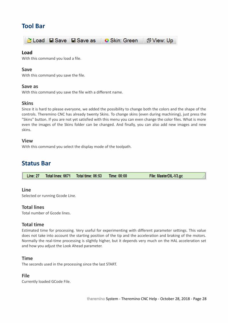
Tool Bar
LoadWith this command you load a file.
SaveWith this command you save the file.
Save asWith this command you save the file with a different name.
SkinsSince it is hard to please everyone, we added the possibility to change both the colors and the shape of thecontrols. Theremino CNC has already twenty Skins. To change skins (even during machining), just press the"Skins" button. If you are not yet satisfied with this menu you can even change the color files. What is moreeven the images of the Skins folder can be changed. And finally, you can also add new images and newskins.
ViewWith this command you select the display mode of the toolpath.
Status Bar
Line Selected or running Gcode Line.
Total linesTotal number of Gcode lines.
Total timeEstimated time for processing. Very useful for experimenting with different parameter settings. This valuedoes not take into account the starting position of the tip and the acceleration and braking of the motors.Normally the real-time processing is slightly higher, but it depends very much on the HAL acceleration setand how you adjust the Look Ahead parameter.
TimeThe seconds used in the processing since the last START.
FileCurrently loaded GCode File.
theremino System - Theremino CNC Help - October 28, 2018 - Page 28

Motor settings in Theremino HAL
Checklist and motor adjustments:
• Control the frequency of repetition (at least 200 fps, but better 500 and over). If necessary increase theparameter CommSpeed (or decrease it to reduce the load on the CPU).
• Set the Pin-type "Stepper", they usually are 3, and they have to be in positions 1, 3 and 5. Its "Stepper_dir" are automatically set and do not require any adjustment.
• Normally Slots for "Stepper" and "StepperDir" are left with the values 1, 2, 3, 4, 5 and 6 (check it)
• Check all Pin-type "Stepper". Select them one by one and check that the three values of the panel "Pinproperties", are 1000, 0 and 100, and that the "Response speed" is disabled.
• For all Pin "Stepper", set the "Steps per mm" that depend on the number of steps per revolution of the motor(usually 200), multiplied by the number of microstep (1, 2, 4, 8, 16 or 32) and finally multiplied, for the pitchof the worm screw, or the ratio of the pulleys (usually x1, x2 or x4)
• For every Pin "Stepper", raise (try and test) "MaxSpeed", trying out the motors with the Slot Viewer (withouttool). Up to detect the speed that makes "shelling" the motor (the motor sounds wiiiii and does not move),and after decrease of 20% to have a safety margin.
• For every Pin "Stepper", raise (try and test) "MaxAcc". Up to detect the acceleration that makes "shelling" themotor, and after decrease of 20% to have a safety margin. Normal values range from 20 ( heavy machines) to200 (light and fast equipment).
To reverse the direction of movement of an axis swap values "1000" and "0" for the numerical fields "1000means mm" and "0 means mm".
Finally we add some Pin of type "Dig_Out", "Pwm_8", "Pwm_16", "Dig_In" or "Dig_In_Pu", for the outputsignals and the input and set their Pin. As explained in the appendix on the InOut signals.
theremino System - Theremino CNC Help - October 28, 2018 - Page 29
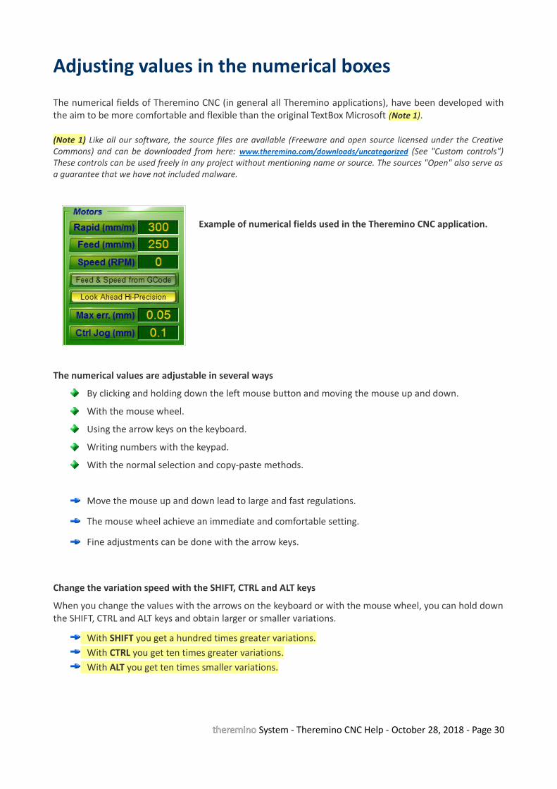
Adjusting values in the numerical boxes
The numerical fields of Theremino CNC (in general all Theremino applications), have been developed withthe aim to be more comfortable and flexible than the original TextBox Microsoft (Note 1).
(Note 1) Like all our software, the source files are available (Freeware and open source licensed under the CreativeCommons) and can be downloaded from here: www.theremino.com/downloads/uncategorized (See "Custom controls")These controls can be used freely in any project without mentioning name or source. The sources "Open" also serve asa guarantee that we have not included malware.
Example of numerical fields used in the Theremino CNC application.
The numerical values are adjustable in several ways
By clicking and holding down the left mouse button and moving the mouse up and down.
With the mouse wheel.
Using the arrow keys on the keyboard.
Writing numbers with the keypad.
With the normal selection and copy-paste methods.
Move the mouse up and down lead to large and fast regulations.
The mouse wheel achieve an immediate and comfortable setting.
Fine adjustments can be done with the arrow keys.
Change the variation speed with the SHIFT, CTRL and ALT keys
When you change the values with the arrows on the keyboard or with the mouse wheel, you can hold downthe SHIFT, CTRL and ALT keys and obtain larger or smaller variations.
With SHIFT you get a hundred times greater variations.With CTRL you get ten times greater variations.With ALT you get ten times smaller variations.
theremino System - Theremino CNC Help - October 28, 2018 - Page 30
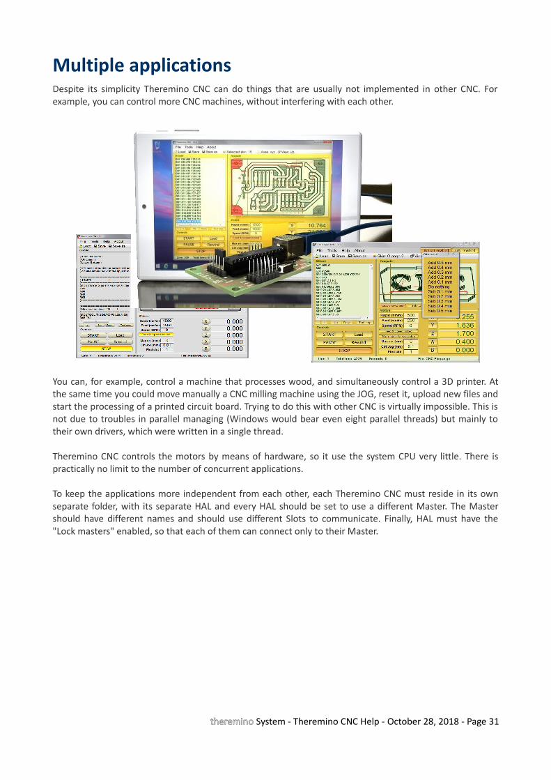
Multiple applications Despite its simplicity Theremino CNC can do things that are usually not implemented in other CNC. Forexample, you can control more CNC machines, without interfering with each other.
You can, for example, control a machine that processes wood, and simultaneously control a 3D printer. Atthe same time you could move manually a CNC milling machine using the JOG, reset it, upload new files andstart the processing of a printed circuit board. Trying to do this with other CNC is virtually impossible. This isnot due to troubles in parallel managing (Windows would bear even eight parallel threads) but mainly totheir own drivers, which were written in a single thread.
Theremino CNC controls the motors by means of hardware, so it use the system CPU very little. There ispractically no limit to the number of concurrent applications.
To keep the applications more independent from each other, each Theremino CNC must reside in its ownseparate folder, with its separate HAL and every HAL should be set to use a different Master. The Mastershould have different names and should use different Slots to communicate. Finally, HAL must have the"Lock masters" enabled, so that each of them can connect only to their Master.
theremino System - Theremino CNC Help - October 28, 2018 - Page 31
Tips for less obvious functions
Start, Stop and EmergencyThe alignment of the machine remains valid even after turning off the machine and PC. It is notnecessary to repeat the zeroing at every start up.
Double clicking on the START button, the processing is started and immediately after paused. Whatyou obtain is a step by step operation (it is performed only one line of Gcode or even only a part ofthe movement, in the case of long shifts).
Doing double-click on the start button is useful in short tests and to be sure that everything isworking well. For example to check that the spindle motor can start.
During processing you can put the machine in pause, pressing START again. This allows you to keepthe focus on the work without the need to move the mouse cursor.
As emergency button you can also use the space bar on the keyboard.
The emergency stop is not a normal STOP : the motors stop without slowing. So you lose the actualposition and you will have to redo the zeroing axis.
You can change the tip and then start again from every point in GCode (it is enough to click on a lineof GCode and press START)
STOP button shows the reasons for the stop.
Toolpath (toolpath)Double-clicking on the tool path, you can locate the GCode corresponding line (better enlarge first,with the mouse wheel)
Clicking the GCode, the performed parts are highlighted (in contrasting color), in the frame thatdisplays the toolpath.
Unlike other CNC, the image of the tool path reminds performed areas (in contrasting color) andthey are shown even after a perspective or size change.
Motion commandsGoto bottom-left and Goto top-right does not move the Z axis
Goto Home and Goto Zero also move the Z axis
The difference between Goto Zero and Goto Home is only the vertical position of axis Z
Slots and First SlotFirst of all you have to match the HAL Slots, with those of Theremino CNC. If they do not matchanything can happen.
Make sure that "First Slot" corresponds to the first Slot on the HAL.
The Slots are in a fixed sequence in CNC Theremino but they can be modified and sent by HAL toany PIN hardware.
A same Slot can also control different motors (eg two motors in gantry).
theremino System - Theremino CNC Help - October 28, 2018 - Page 32
Appendix 1 - Machining speed
The movement speed, "Rapid" and "Feed", can be set with any value, even very high value. The actualspeed and acceleration of the motors, are then limited by the firmware (adjustments in the HALapplication), because of this you can be sure that the motors never loose steps. But you should not setRapid and Feed Speed to higher values than those set in the application HAL for the slowest motor.
At the beginning it is normal to have all the parameters not correctly adjusted. You have to test a lot inorder to find a right balance. This balance depends on both the machine and the motors, on the HALadjustments and the type of work that they do.
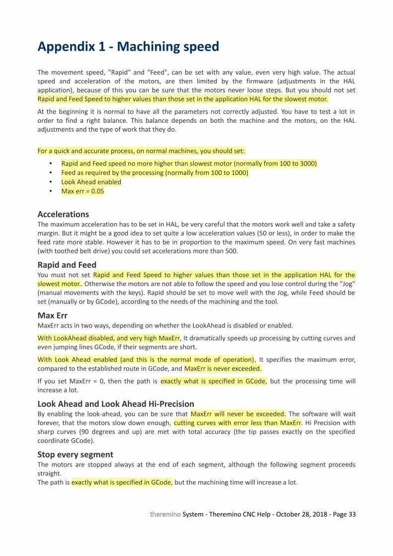
For a quick and accurate process, on normal machines, you should set:
• Rapid and Feed speed no more higher than slowest motor (normally from 100 to 3000)• Feed as required by the processing (normally from 100 to 1000)• Look Ahead enabled• Max err = 0.05
Accelerations The maximum acceleration has to be set in HAL, be very careful that the motors work well and take a safetymargin. But it might be a good idea to set quite a low acceleration values (50 or less), in order to make thefeed rate more stable. However it has to be in proportion to the maximum speed. On very fast machines(with toothed belt drive) you could set accelerations more than 500.
Rapid and FeedYou must not set Rapid and Feed Speed to higher values than those set in the application HAL for theslowest motor.. Otherwise the motors are not able to follow the speed and you lose control during the "Jog"(manual movements with the keys). Rapid should be set to move well with the Jog, while Feed should beset (manually or by GCode), according to the needs of the machining and the tool.
Max ErrMaxErr acts in two ways, depending on whether the LookAhead is disabled or enabled.
With LookAhead disabled, and very high MaxErr, It dramatically speeds up processing by cutting curves andeven jumping lines GCode, if their segments are short.
With Look Ahead enabled (and this is the normal mode of operation), It specifies the maximum error,compared to the established route in GCode, and MaxErr is never exceeded.
If you set MaxErr = 0, then the path is exactly what is specified in GCode, but the processing time willincrease a lot.
Look Ahead and Look Ahead Hi-PrecisionBy enabling the look-ahead, you can be sure that MaxErr will never be exceeded. The software will waitforever, that the motors slow down enough, cutting curves with error less than MaxErr. Hi Precision withsharp curves (90 degrees and up) are met with total accuracy (the tip passes exactly on the specifiedcoordinate GCode).
Stop every segmentThe motors are stopped always at the end of each segment, although the following segment proceedsstraight.The path is exactly what is specified in GCode, but the machining time will increase a lot.
theremino System - Theremino CNC Help - October 28, 2018 - Page 33
Appendix 2 - The calculation of the trajectory
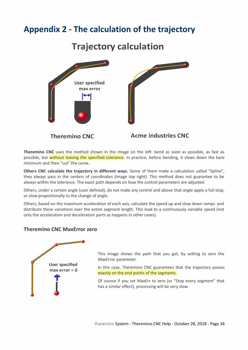
Theremino CNC uses the method shown in the image on the left: bend as soon as possible, as fast aspossible, but without leaving the specified tolerance. In practice, before bending, it slows down the bareminimum and then "cut" the curve.
Others CNC calculate the trajectory in different ways. Some of them make a calculation called "Spline",they always pass in the centers of coordinates (image top right). This method does not guarantee to bealways within the tolerance. The exact path depends on how the control parameters are adjusted.
Others, under a certain angle (user defined), do not make any control and above that angle apply a full stop,or slow proportionally to the change of angle.
Others, based on the maximum acceleration of each axis, calculate the speed up and slow down ramps anddistribute these variations over the entire segment length. This lead to a continuously variable speed (notonly the acceleration and deceleration parts as happens in other cases).
Theremino CNC MaxError zero
This image shows the path that you get, by setting to zero theMaxError parameter.
In this case, Theremino CNC guarantees that the trajectory passesexactly on the end points of the segments.
Of course if you set MaxErr to zero (or "Stop every segment" thathas a similar effect), processing will be very slow.
theremino System - Theremino CNC Help - October 28, 2018 - Page 34
Appendix 3 - Processing timesThe processing time "Total time" is continuously updated, based on loaded GCode and on settings of"Rapid", "Feed" and "Feed locked" (but does not take into account the preparatory movements).
If the motors are turned off or disconnected or if you set "Look Ahead disabled" then the software waits foracceleration and deceleration. In these conditions the processing time is equal to the calculated "Totaltime" (or even lower if you rise a lot the "MaxErr").
If motors are connected and you use the "Look Ahead", then the processing time increases, with sometuning it could even double.
A processing time much greater than the calculated, indicates that wrong parameters are being used.
Some examples of machining timesTimes measured on file "AdapterSplit5V.gc", with Rapid = 300, Feed = 300, Feed locked enabled, Max err. = 0.05 andaccelerations = 50 mm/sxs
• Look Ahead Disabled: 60 seconds (exactly equal to the calculated "Total Time") • Look Ahead Enabled: 64 seconds (+ 6%)• Look Ahead Hi-Precision: 68 seconds (+ 13%)• Stop every segment: 87 seconds (+ 45%)
Times measured on file "AdapterSplit5V.gc", with Rapid = 500, feed = 500, Feed locked enabled, Max err. = 0.05 andaccelerations = 50 mm /sxs
• Look Ahead Disabled: 34 seconds (less than 36 sec calculated - Note 1)• Look Ahead Enabled: 47 seconds (+ 30%)• Look Ahead Hi-Precision: 51 seconds (+ 42%)• Stop every segment: 74 seconds (+ 120%)
Note 1 - With "Look Ahead disabled" and "Max Err" greater than zero, you cut the corners and you can get processingtimes even lower than the calculated ones.
Which Look Ahead use• Look Ahead Disabled - To be used rarely and carefully. If you increase MaxErr processing time will
be shortened considerably, cutting the curve and jump whole segments. But the position and speederrors can become intolerable and you can even break the tools.
• Look Ahead Enabled - Fast processing and adjustable accuracy. Raising MaxErr and accepting smallerrors in position and velocity can greatly shorten the time. Adjust MaxErr rather low, usually 0.05or 0.1 mm.
• Look Ahead Hi-Precision - This might be a good choice for all processes. The processing timeincreases only a little, but the feed speed is set with precision and the tool passes exactly at thecoordinates in tight bends (angles of 90 degrees or more). Adjust MaxErr rather low, usually 0.05 or0.1 mm.
• Stop every segment - This setting is seldom used. For each line of GCode stop all the motors.MaxErr is disabled and the tool follows exactly the coordinates.
theremino System - Theremino CNC Help - October 28, 2018 - Page 35

Appendix 4 - Implemented FunctionsG00 = Rapid modeG01 = Work modeG02 = Clockwise circular interpolation G03 = Counterclockwise circular interpolationG04 = Dwell time specified by prefixes or U P (U = seconds, P = milliseconds)G05 = Progress Stop (Pause)G09 = Exact Stop - not modal (manual in Theremino CNC)G17 = Working on the X / Y levelG21 and G71 = Millimeters modeG28 = Goto HOME (Meaning different in some machines. Read the appendix on the G28)G40 = Cancellation of tool compensationG49 = Cancellation of tool length compensationG61 ... G64 = Enable and disable exact stop G62 = Automatic corner override (automatic in Theremino CNC)G80 = Erase "canned" cycles G90 = Absolute coordinatesG91.1 = Return to normal incremental mode for parameters I / J / KG92 Enn = Set the extruder to valore nn (without moving the motor)G93 = "Inverse time" mode (F = 1 / duration of the motion in minutes)G94 = Back to normal feed mode (F = mm / min)
M00 = Program Stop (Stop)M01 = Optional Program Stop (Pause)M02 = End of program (Stop)M03 M04 = Spindle Rotation clockwise (M03) and counterclockwise (M04)M05 = Stop spindle rotationM06 = Tool changeM07 = Refrigerant 1M08 = Refrigerant 2M09 = Stop refrigerantM10 M11 = Work piece Locking and unlocking M13 M14 = Activation refrigerant 1 and spindle rotation clockwise (M13) or anticlockwise (M14)M19 = Spindle orientation, in degrees, defined by the letter "C"M30 = End of program (Stop)M31 = Suspension (Pause)M41 ... M44 = Speed rangesM50 = Refrigerant 3M51 = Refrigerant 4M84 = Machine disable (acts on the “IN-OUT enabled” button)M99 = End of subroutine (Stop)
() = CommentF = Feed speedS = Spindle rotation speedN = Number of lineI, J, K, R = Circular interpolations parameters X, Y, Z, A, B = Destination for each axis (are also valid U and V that are translated into A and B)C = Rotation Z axis (in degrees) for spindle orientation.
theremino System - Theremino CNC Help - October 28, 2018 - Page 36
Implemented functions - 3D printers specific functions
M 82 - Set extruder to absolute mode (default for 3D printers - does nothing)M 84 - Disable motors
M 105 - Read the current temperature (system implemented - does nothing)
M 106 - Fans ONM 107 - Fans OFF
M 104 - Set the selected extruder temperature (Example: M104 S190 - temperature = 190°C)M 109 - Set the selected extruder temperature and wait (Example: M109 S215 - temperature = 215°C)M 140 - Set print bed temperature (Example M140 S190 - temperature = 190°C) M 141 - Set chamber temperature (Example: M141 S90 - temperature = 90°C)
- - - - - - - - - - -
The temperature control tables are in the file “TemperatureTables.txt”, acccessible by the menu “3DPrinters”.
Instructions for temperature sensors and tables are in the Appendix 23
theremino System - Theremino CNC Help - October 28, 2018 - Page 37
Appendix 5 - Not Implemented FunctionsAs stated in the presentation, Theremino CNC implements only the basic functions. We do not want it tobecome, like other applications, so complex to need to to ask for help to “San Gennaro” in order to use it.
All not implemented codes could be replaced by only G00 and G01, just instruct the CAM post-processor.Twenty years ago there were floppy disks, but today in 2015 no longer makes sense risking errors just tosave something like 100K in the memory occupation of the file.
In the Theremino system it is possible to use an automation programming language which is more advancedthan GCode. The hardware and software modularity allows you to program complex systems and writecomplex algorithms, virtually not possible in GCode. For example read the Web-cam or program a PID withanalogue sensors. (Note 3)
G53 G54 (and all codes that indicate machine coordinates and work piece coordinates) - Theremino CNC alwaysworks in relative coordinates (work piece coordinates). No machine coordinates.
Codes from G41 to G59 - The tool diameter compensation (from G41 to G52) is done in the CAM (Note 1). WithTheremino CNC the zero offset (G54 to G59) are performed manually with JOG (Note 2). Using inches or incrementalprogramming, coordinates GCode are different from the actual coordinates of the tool, with all the difficulties thatcome with it. Drilling cycles (G81 to G 89) work, but Theremino CNC does not consider them different from otherprocessing cycles.
Codes from G61 to G83 - For example the G83 specify that the tip must go down a number of times and each timetrace a little "backed off a bit", http://linuxcnc.org/docs/html/gcode/gcode.html#sec:G83-Drilling-Peck. But this "a little" ofa machining operation, may be a "too" for another. Also allowing the G83, would open the door to a Pandora's jar ofpossible bugs, because then you enqueue the G82, G81, G76, G73, G64, G61, which are also different on differentmachines. It is better to tell the CAM to replace everything with G00 and G01. This will make the CAM itself to be theowner of any movement and can adjust the "a little" in the best way, for each job.
Backlash compensation - A "patch" that creates more troubles than it solves - By Mach3 manual: ".... Compensation is a"last resort" when the mechanical design of your machine .... can not overcome problems with the machine in continuous cutting ....by using the constant speed is lost .... Mach3 does not respect most parameters of acceleration and you risk losing steps ". From theoriginal manual Mach3: "Backlash compensation is a "last resort" when the mechanical design of your machine .... it can notovercome problems with the machine in continuous cutting. ... Using Generally it will disable the "constant velocity" features at"corners". ... Mach3 Able you is not fully honor the axis acceleration parameters .... When compensating for backlash so steppersystems Generally will have to be detuned to avoid risk of lost steps. "(Note 1) A CNC application does not know the size of the tool and not even the shape and position of the work piece. Writingparameters disguised as comments is a distortion of the meaning of GCode that, rightly, not provides for them. (Note 2) Place pieces side by side depends on the size of the raw part that is available. Fixed positions in GCode do lose more timethan they save. When you make a habit to use the JOG manual, make more pieces in different locations is easy and immediate.(Note 3) GCode is not a good programming language, it is not structured and uses commands like GOTO, well known for generating“spaghetti code”. In Theremino system the automation software is written in modern languages, objects and structured (VB6,VBNET, C ++, CSharp, Python, Theremino Script, Theremino Automation, MaxMSP etc ..)
theremino System - Theremino CNC Help - October 28, 2018 - Page 38
Appendix 6 - The circular interpolations G02 and G03
We have implemented the circular interpolations because many have asked. But we have never liked themand still we do not like them. They are implemented well and work exactly how they should work, but ouradvice is not to use them. They have inherent flaws in the definition of the command:
• It is not possible to use them on machines with 3, 4 or 5 axes, if not with a "indexed" functioning. Inother words, G02 and G03 move up to two axes at the same time, and the other axes mustnecessarily stand still. Instead, G00 and G01 movements are true multidimensional and can move asingle axis, two, three, four or even all five axes simultaneously.
• G02 and G03, being limited to only two axes, are operated separately, and disturb the smoothfunctioning and the multidimensional calculations of Look Ahead. The movements on several axes isnecessarily split across several Gcode lines and then it will be performed indexed (an euphemismnot to say "jerky"). With G02 and the G03 the indexed operation is inevitable, it happens on anyCNC, not only on Theremino CNC.
• The parameters that defines the circle arc are inconsistent. For example it is possible that thedestination contradicts as specified by the origin and by the center of rotation. So what should youdo? Discard the command? Ask the user what to do? Stop processing and ruin the piece? Run thesame command and scratch the piece? Some may say that a warning is enough and let the usercorrect the command. But usually it is just inaccuracies due to rounding. And the user should dodifficult trigonometric calculations. It is better to avoid them and use only commands that areinternally consistent.
• There is also a version of G02 and G03 that specifies the radius, instead of the center of rotation.The intention of those who designed this version of the command was to eliminate theinconsistency of the parameters. It is a pity that with this version you can not do a full circle, andthat to do is to break the circle in three lines, or use the inconsistent version of the command.
• On some CNC it is not possible to make a circle, not even with the version of G02 and G03 whichspecifies the center of rotation.
• In the command definition the rotation direction is not clearly established. The direction is definedas "clockwise" or "counterclockwise", but what does "clockwise" mean in a multidimensionalenvironment? Where is the observer compared to the bow, in front, behind, above or below? Wesolved this problem by copying exactly the behavior of METACUT and Mach3. But we found someGCode examples which are run by Mach3 in a certain direction and by METACUT in the oppositedirection.
• We also found cases of G02 which METACUT performs regularly but Mach3 not. Probably theparameters have minimal inconsistencies, due to rounding, but Mach3 instead of giving an error,simply skip them and go to the next line.
• Internet is full of cases of problems caused by codes G02 and G03. Look for "G02 errors" and youwill find that they have caused any kind of defect. And these are not small flaws, the tool may breakor do even worse damages, because it is in a completely different position than the calculated one.
In conclusion, G02 and G03 are born evil and are not essential. Just tell the post-processor of the CAM notto use them and the only disadvantage is that you have files a bit 'longer. When you used the floppy diskfrom 700k, 100k savings could be useful, but now it no longer makes sense.
theremino System - Theremino CNC Help - October 28, 2018 - Page 39

Appendix 7 - HOME Controls (G28 and following)
Caution: Do not trust HOME command. They may be performed differently from how you are used to. Insome GCode you may need to add one or more preparatory movements.
Since Theremino CNC is a generic application (for cutters, 3D printers, cutting polystyrene, laser cutting,engraving and special machines) preparatory movements, useful in some cases, may be arbitrary anddangerous in others. So Theremino CNC does not perform preparatory movements, when it meets a G28code it goes directly to the home point.
To avoid interference with the work piece it may be necessary to precede the G28 with:
• G00 ZNN (to lift the tip up to a security level)
• G00 X0 Y0 (if you want that the movement to zero X and Y precedes the movement Z)
- - - - - - -
Implementations variables command from G28 to G32
We have implemented the command G28 because it is widely used, but its implementation will change on differentmachines.
• G28 - Go to Predefined Position (Linux CNC)
• G28 - Goto Home (Machine for 3D printing trade)
• G28 - Machine zero, aka machine reference point (Wikipedia)
• G28 - Goto Home Location coordinates (Manual Mach3)
• G28 - Moves to the supplied axis back to the zero end stops as quickly as it can (RepRap wiki)
As you can see it is not always the same point, it may be the "Machine zero", or a predefined point by another GCode,or a point that you specify in certain fields of the application (Mach3).
Also there are no rules whether the route should be performed in 3D, or if some axis must be moved before others.And in this case which axis you must move first. And what the axes A and B have to do for machines cuttingpolystyrene.
The G28.1 that means Home position on some machines, is instead starting a scan of the reset switches on othermachines.
The commands of the secondary HOME (from G30 to G32) are even more variables (test of the printing level on somemachines, skip the measurement functions on others).
- - - - - -
We verified what they do in practice some machines and found very different behaviors.
For example, a Cubex (3D printer trade) when process a G28 makes these movements:
1. Moves the plan down to 10 mm
2. It moves the X and Y together until X = zero and Y = zero
3. Move the floor up to Z = zero
The preparatory movement of 10 mm (which is safe for a 3D printer) could instead be dangerous (or worthless or notenough) for a cutter. And before moving X and Y of Z, it could cause a collision with the work piece.
theremino System - Theremino CNC Help - October 28, 2018 - Page 40
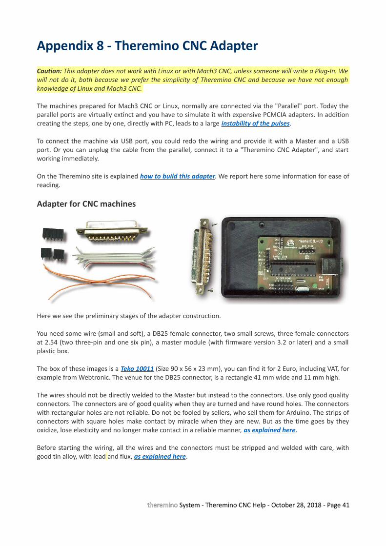
Appendix 8 - Theremino CNC Adapter
Caution: This adapter does not work with Linux or with Mach3 CNC, unless someone will write a Plug-In. Wewill not do it, both because we prefer the simplicity of Theremino CNC and because we have not enoughknowledge of Linux and Mach3 CNC.
The machines prepared for Mach3 CNC or Linux, normally are connected via the "Parallel" port. Today theparallel ports are virtually extinct and you have to simulate it with expensive PCMCIA adapters. In additioncreating the steps, one by one, directly with PC, leads to a large instability of the pulses.
To connect the machine via USB port, you could redo the wiring and provide it with a Master and a USBport. Or you can unplug the cable from the parallel, connect it to a "Theremino CNC Adapter", and startworking immediately.
On the Theremino site is explained how to build this adapter. We report here some information for ease ofreading.
Adapter for CNC machines
Here we see the preliminary stages of the adapter construction.
You need some wire (small and soft), a DB25 female connector, two small screws, three female connectorsat 2.54 (two three-pin and one six pin), a master module (with firmware version 3.2 or later) and a smallplastic box.
The box of these images is a Teko 10011 (Size 90 x 56 x 23 mm), you can find it for 2 Euro, including VAT, forexample from Webtronic. The venue for the DB25 connector, is a rectangle 41 mm wide and 11 mm high.
The wires should not be directly welded to the Master but instead to the connectors. Use only good qualityconnectors. The connectors are of good quality when they are turned and have round holes. The connectorswith rectangular holes are not reliable. Do not be fooled by sellers, who sell them for Arduino. The strips ofconnectors with square holes make contact by miracle when they are new. But as the time goes by theyoxidize, lose elasticity and no longer make contact in a reliable manner, as explained here.
Before starting the wiring, all the wires and the connectors must be stripped and welded with care, withgood tin alloy, with lead and flux, as explained here.
theremino System - Theremino CNC Help - October 28, 2018 - Page 41
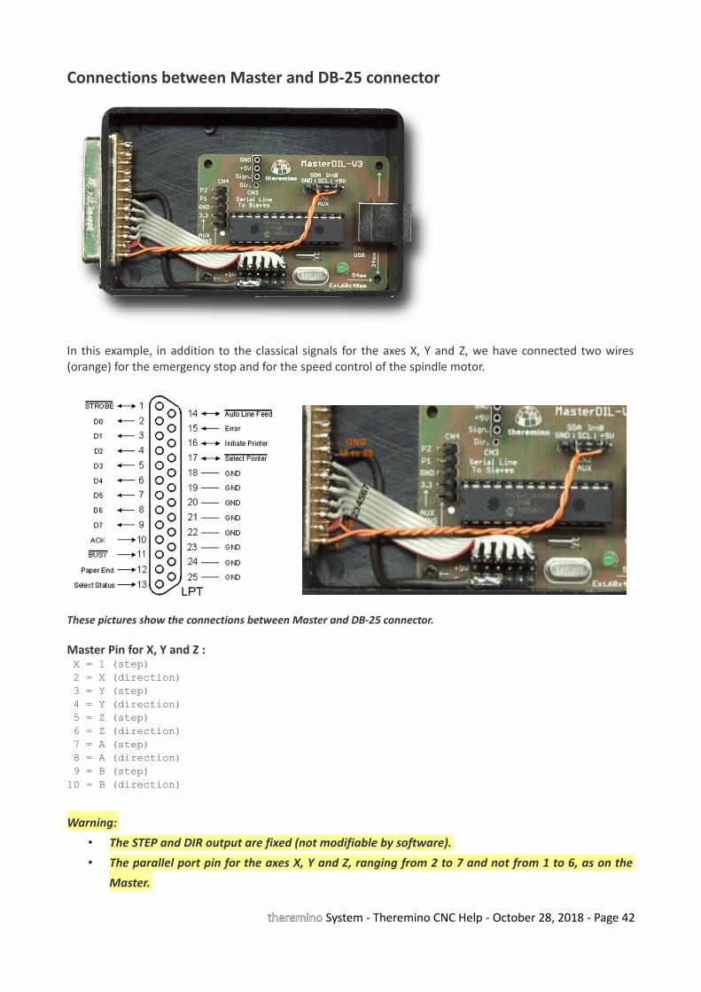
Connections between Master and DB-25 connector
In this example, in addition to the classical signals for the axes X, Y and Z, we have connected two wires(orange) for the emergency stop and for the speed control of the spindle motor.
These pictures show the connections between Master and DB-25 connector.
Master Pin for X, Y and Z : X = 1 (step) 2 = X (direction) 3 = Y (step) 4 = Y (direction) 5 = Z (step) 6 = Z (direction) 7 = A (step) 8 = A (direction) 9 = B (step)10 = B (direction)
Warning:
• The STEP and DIR output are fixed (not modifiable by software).
• The parallel port pin for the axes X, Y and Z, ranging from 2 to 7 and not from 1 to 6, as on the
Master.
theremino System - Theremino CNC Help - October 28, 2018 - Page 42
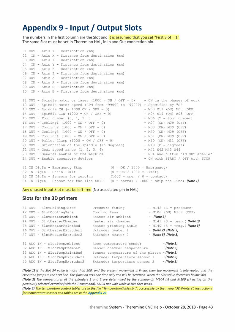
Appendix 9 - Input / Output SlotsThe numbers in the first column are the Slot and it is assumed that you set "First Slot = 1".The same Slot must be set in Theremino HAL, in In and Out connection pin.
01 OUT - Axis X - Destination (mm)02 IN - Axis X - Distance from destination (mm)03 OUT - Axis Y - Destination (mm)04 IN - Axis Y - Distance from destination (mm)05 OUT - Axis Z - Destination (mm)06 IN - Axis Z - Distance from destination (mm)07 OUT - Axis A - Destination (mm)08 IN - Axis A - Distance from destination (mm)09 OUT - Axis B - Destination (mm)10 IN - Axis B - Distance from destination (mm)
11 OUT - Spindle motor or laser (1000 = ON / OFF = 0) - ON in the phases of work12 OUT - Spindle motor speed (RPM from -99000 to +99000) - Specified by "S"13 OUT - Spindle CW (= 1000 ON / OFF = 0) - M03 M13 (ON) M05 (OFF)14 OUT - Spindle CCW (1000 = ON / OFF = 0) - M04 M14 (ON) M05 (OFF)15 OUT - Tool number (0, 1, 2, 3 ...) - M06 (T = tool number)16 OUT - Cooling1 (1000 = ON / OFF = 0) - M07 (ON) M09 (OFF)17 OUT - Cooling2 (1000 = ON / OFF = 0) - M08 (ON) M09 (OFF)18 OUT - Cooling3 (1000 = ON / OFF = 0) - M50 (ON) M09 (OFF)19 OUT - Cooling4 (1000 = ON / OFF = 0) - M51 (ON) M09 (OFF)20 OUT - Pallet Clamp (1000 = ON / OFF = 0) - M10 (ON) M11 (OFF)21 OUT - Orientation of the spindle (in degrees) - M19 (C = degrees)22 OUT - Gear speed range (1, 2, 3, 4) - M41 M42 M43 M4423 OUT - General enable of the machine - M84 and button "IN OUT enable"24 OUT - Enable accessory devices - ON with START / OFF with STOP
31 IN DigIn - Emergency Stop (0 = OK / 1000 = Emergency)32 IN DigIn - Chain Limit (0 = OK / 1000 = limit)33 IN DigIn - Sensors for zeroing (1000 = open / 0 = contact)34 IN DigIn - Sensor for the line SKIP (0 = normal / 1000 = skip the line) (Note 1)
Any unused Input Slot must be left free (No associated pin in HAL).
Slots for the 3D printers
41 OUT - SlotHoldingForce Pressure fixing - M142 (S = pressure)42 OUT - SlotCoolingFans Cooling fans - M106 (ON) M107 (OFF)43 OUT - SlotHeaterAmbient Heater air ambient - (Note 3)44 OUT - SlotHeaterChamber Heater air chamber - M141 (S = temp.) (Note 3)45 OUT - SlotHeaterPrintBed Heater printing table - M140 (S = temp.) (Note 3)46 OUT - SlotHeaterExtruder1 Extruder heater 1 - (Note 2) (Note 3)47 OUT - SlotHeaterExtruder2 Extruder heater 2 - (Note 3) (Note 3)
51 ADC IN - SlotTempAmbient Room temperature sensor - (Note 3)52 ADC IN - SlotTempChamber Sensor chamber temperature - (Note 3)53 ADC IN - SlotTempPrintBed Sensor temperature of the platen - (Note 3)54 ADC IN - SlotTempExtruder1 Extruder temperature sensor 1 - (Note 3)55 ADC IN - SlotTempExtruder2 Extruder temperature sensor 2 - (Note 3)
(Note 1) If the Slot 34 value is more than 500, and the present movement is linear, then the movement is interrupted and theexecution jumps to the next line. This function acts one time only and will be 'rearmed' when the Slot value decreases below 500.(Note 2) The temperatures of the extruders 1 and 2 are determined by the commands M104 (s) and M109 (s) acting on thepreviously selected extruder (with the T command). M104 not wait while M109 does waits.(Note 3) The temperature control tables are in the file “TemperatureTables.txt”, acccessible by the menu “3D Printers”. Instructionsfor temperature sensors and tables are in the Appendix 23
theremino System - Theremino CNC Help - October 28, 2018 - Page 43
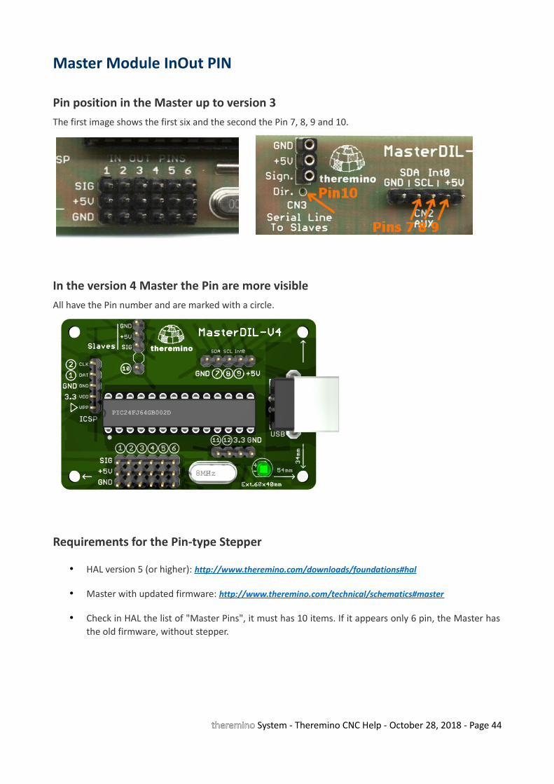
Master Module InOut PIN
Pin position in the Master up to version 3The first image shows the first six and the second the Pin 7, 8, 9 and 10.
In the version 4 Master the Pin are more visibleAll have the Pin number and are marked with a circle.
Requirements for the Pin-type Stepper
• HAL version 5 (or higher): http://www.theremino.com/downloads/foundations#hal
• Master with updated firmware: http://www.theremino.com/technical/schematics#master
• Check in HAL the list of "Master Pins", it must has 10 items. If it appears only 6 pin, the Master hasthe old firmware, without stepper.
theremino System - Theremino CNC Help - October 28, 2018 - Page 44

Output signals
The output signals are valid even if the process starts from an intermediate GCode line. At the Start timethe control codes are searched backwards in GCode and the most recent is used. If a code is not found itsoutput signal is turned off ( Slot value = 0).
The signal of the Slot 11 is controlled only by the application and during work is always on. It serves tocontrol laser and similar tools, it is turned on during processing and switched off during rapid movements.
With some CNC every time you press START, you are living a moment of fear: "The spindle motor will turnon? Or maybe in GCode is missing the code to start it, so it will not move and I will break the tool?". ButTheremino CNC has this signal, which is turned on by the application and not by GCode. So (if you prefer)you can configure the hardware, for the lighting of the spindle, not be dependent on GCode. Withappropriate AND and OR (hardware or software), the ON-OFF signal with the other output signals, you cangenerate suitable signals for machines of any type (laser, cutting, spray, etc ...)
The signal of the Slot 12 is controlled by the "Speed RPM" filed and also from GCode if "Feed locked" isdisabled.
The signals of the Slots from 13 to 20 are controlled by M codes:• 1 output tool change, with the number (Tnn) tool (M06) • 4 separate outputs for refrigerants (M07 M08 M50 M51) (M09 and to turn off)• 1 output for locking and unlocking of the piece (M10 and M11)• 1 out of spindle orientation in degrees (M19)• 1 output for 4 speed ranges (gear) (M41 M42 M43 M44)
Auxiliary connectionsA single Master, in addition to the axes X, Y and Z, can control other four signals, with Pin 7, 8, 9 and 10.These signals can be generic IN-OUT or can control other two motors (in Theremino CNC they are called Aand B). The special connection, for controlling the spindle speed, for the power of the laser, for theemergency button and switches for end stroke, are to be studied from time to time. Follow the links, whichwere made by Mach3, the list "Ports and Pins" in Mach3, and InOut table on the previous page.
ENABLE signal of the motorsThe controllers have always an "Enable" input and it is natural to ask where to connect it. We recommendthat you DO NOT connect to the software. This saves a Pin, which might be more useful for other functions,it also increases the security of maintaining alignment with the motors.
Theremino CNC remains aligned to the motors and it does not require constant resets. Even after turningoff the machine and after turning off and restarting the PC, it remains aligned. You can do tests with poweroff, using the button "IN OUT enabled", which restores the coordinates when it is enabled again.
But if you disable the HAL or if you turns off the power of the machine and perform a movement thealignment is lost. So we recommend this sequence: (1) Turn on the machine, (2) Start Theremino CNC, (3)Work without turning off the machine or motors, (4) Turn off Theremino CNC, (5) Turn off the machine.
To check GCode, edit and execute it without motors it is better to prepare a copy of Theremino CNC, in aseparate folder and use it with the buttons "IN OUT enabled" and "HAL enabled" always off.
theremino System - Theremino CNC Help - October 28, 2018 - Page 45
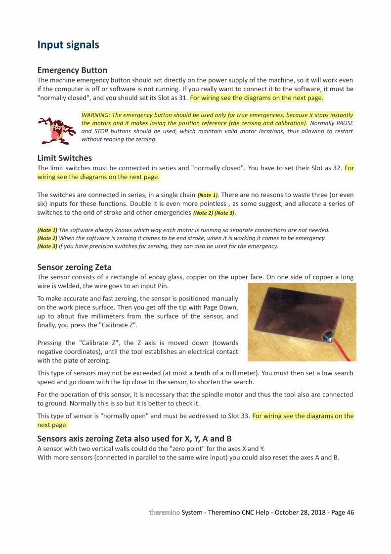
Input signals
Emergency ButtonThe machine emergency button should act directly on the power supply of the machine, so it will work evenif the computer is off or software is not running. If you really want to connect it to the software, it must be"normally closed", and you should set its Slot as 31. For wiring see the diagrams on the next page.
WARNING: The emergency button should be used only for true emergencies, because it stops instantlythe motors and it makes losing the position reference (the zeroing and calibration). Normally PAUSEand STOP buttons should be used, which maintain valid motor locations, thus allowing to restartwithout redoing the zeroing.
Limit SwitchesThe limit switches must be connected in series and "normally closed". You have to set their Slot as 32. Forwiring see the diagrams on the next page.
The switches are connected in series, in a single chain (Note 1). There are no reasons to waste three (or evensix) inputs for these functions. Double it is even more pointless , as some suggest, and allocate a series ofswitches to the end of stroke and other emergencies (Note 2) (Note 3).
(Note 1) The software always knows which way each motor is running so separate connections are not needed.(Note 2) When the software is zeroing it comes to be end stroke, when it is working it comes to be emergency.(Note 3) If you have precision switches for zeroing, they can also be used for the emergency.
Sensor zeroing ZetaThe sensor consists of a rectangle of epoxy glass, copper on the upper face. On one side of copper a longwire is welded, the wire goes to an input Pin.
To make accurate and fast zeroing, the sensor is positioned manuallyon the work piece surface. Then you get off the tip with Page Down,up to about five millimeters from the surface of the sensor, andfinally, you press the "Calibrate Z".
Pressing the "Calibrate Z", the Z axis is moved down (towardsnegative coordinates), until the tool establishes an electrical contactwith the plate of zeroing.
This type of sensors may not be exceeded (at most a tenth of a millimeter). You must then set a low searchspeed and go down with the tip close to the sensor, to shorten the search.
For the operation of this sensor, it is necessary that the spindle motor and thus the tool also are connectedto ground. Normally this is so but it is better to check it.
This type of sensor is "normally open" and must be addressed to Slot 33. For wiring see the diagrams on thenext page.
Sensors axis zeroing Zeta also used for X, Y, A and BA sensor with two vertical walls could do the "zero point" for the axes X and Y.With more sensors (connected in parallel to the same wire input) you could also reset the axes A and B.
theremino System - Theremino CNC Help - October 28, 2018 - Page 46
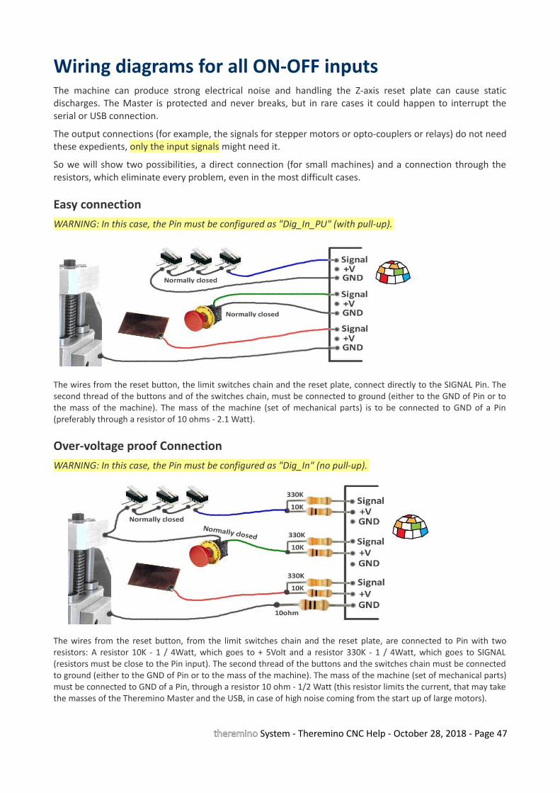
Wiring diagrams for all ON-OFF inputsThe machine can produce strong electrical noise and handling the Z-axis reset plate can cause staticdischarges. The Master is protected and never breaks, but in rare cases it could happen to interrupt theserial or USB connection.
The output connections (for example, the signals for stepper motors or opto-couplers or relays) do not needthese expedients, only the input signals might need it.
So we will show two possibilities, a direct connection (for small machines) and a connection through theresistors, which eliminate every problem, even in the most difficult cases.
Easy connectionWARNING: In this case, the Pin must be configured as "Dig_In_PU" (with pull-up).
The wires from the reset button, the limit switches chain and the reset plate, connect directly to the SIGNAL Pin. Thesecond thread of the buttons and of the switches chain, must be connected to ground (either to the GND of Pin or tothe mass of the machine). The mass of the machine (set of mechanical parts) is to be connected to GND of a Pin(preferably through a resistor of 10 ohms - 2.1 Watt).
Over-voltage proof ConnectionWARNING: In this case, the Pin must be configured as "Dig_In" (no pull-up).
The wires from the reset button, from the limit switches chain and the reset plate, are connected to Pin with tworesistors: A resistor 10K - 1 / 4Watt, which goes to + 5Volt and a resistor 330K - 1 / 4Watt, which goes to SIGNAL(resistors must be close to the Pin input). The second thread of the buttons and the switches chain must be connectedto ground (either to the GND of Pin or to the mass of the machine). The mass of the machine (set of mechanical parts)must be connected to GND of a Pin, through a resistor 10 ohm - 1/2 Watt (this resistor limits the current, that may takethe masses of the Theremino Master and the USB, in case of high noise coming from the start up of large motors).
theremino System - Theremino CNC Help - October 28, 2018 - Page 47
Appendix 10 - Rules for electrical connectionsWhen using high power motors and high power supplies, the power lines and earthing lines should bearranged professionally, otherwise you may experiment communication interruptions at each motorstarting.
The grounding should always be arranged star like, so as to provide paths that do not pass through theelectronic circuits.
The earthing paths of both high inrush currents and powerful power supplies should never go through theMaster, the Slave serial line or through USB line. This is not because electronics weakness, but insteadbecause every device must be wired according to these rules.
Even the micro of the very expensive professional controller would crash if the grounding were done badlybut of course in professional appliances electrical connections are made as they should.
An easy way, which does not require much and work for sure is to keep completely separate grounding andpower supplies of motors from power and grounding of PC. Doing so there is no galvanic connection withthe Master, with the USB and the PC and consequently, driving all that it is NOT powered by the USB,through opto-couplers.
An example of problems caused by the inrush currentIn the milling cutter that we have in the laboratory, the two suction motors were driven with a mosfet, froma 24 V dc power supply. The ground was in common with the Master and the PC.
The trouble was that the steppers did “ghost” steps when the vacuum were turned on and sometimes evenwhen the fluorescent lamps were switched on.
We have blamed the controller of the stepper motors for a long time before finding out what it was.
Now the motor supply has an opto-coupler and its power supply is completely separate, with no galvanicconnection with the PC. With this solution the problem has been completely solved.
theremino System - Theremino CNC Help - October 28, 2018 - Page 48

Appendix 11 - opto-couplers
The opto-couplers are not necessary, as you may think, to protect the Master or the PC. The Master is verysturdy and never breaks and the PC is still protected by PIC which is located on the Master. In really severecases the PIC acts as a fuse and you can change it with only three euro.
Insulation with opto-couplers has the aim to avoid ground loops which can lead to extremely highinstantaneous currents, in the motors and relays switching time.
Strong currents on the ground pass along the entire chain from the machine to the PC towards the groundof the electrical system (so it is better to use notebooks without ground connection).
Strong currents along the ground can cause false steps and also can cause communication errors or eveninterrupt the communication with the PC. This situation gets worse when it comes to drive powerful motorsand could be negligible if it is just to drive the stepper.
One thing not to do is go to the spindle motor with two wires (signal and ground) connected to the Master.It is better to connect the ground of the control spindle (negative reference) to the mass of the machine andfrom there also the mass of the PC, and finally bring the signal wire from the Master to the controller of thespindle.
For safety it would be good to add a 10K resistor along the signal wire (Assuming that the controller has ahigh input impedance)
- - - - - -
Using opto-couplers can only give advantages, but the PCB of the driver becomes much larger and expensive. We are planning to design a separate module with opto-couplers. In this way you could start without and add them only if really needed.
In fact it is a module that anyone would know how to do in 10 minutes on a prototype PCB, so we postponeit.
In any case you must use fast opto-couplers, 6N135type or similar. The fast opto-couplers require a supplyvoltage.
In case of parallel Adapter there is not the 5 Volt onside parallel. So you can not (or would be verycomplex) add the opto-couplers.
In the case of small cutters (more or less all those forhobby) and provided that the spindle motor is opto-coupled and that the motor of the suction is too opto-coupled and that the disposition of grounding is well done ... then the stepper opto-couplers may beomitted.The Proxxon we have in the laboratory has been running for a month with Theremino CNC and also theprototype with four motors, on a wooden board, is working without opto-couplers and the Master neverlost communication (but of course the grounding is well-done and star shaped).
theremino System - Theremino CNC Help - October 28, 2018 - Page 49
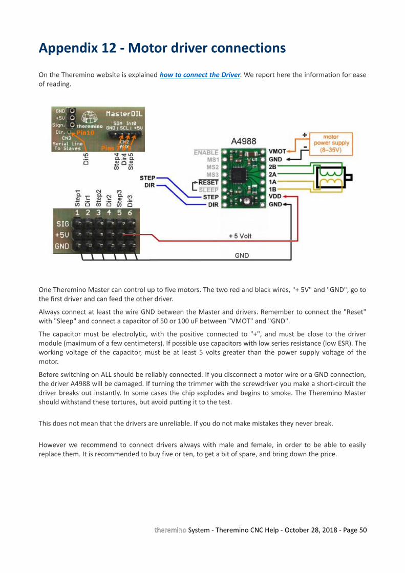
Appendix 12 - Motor driver connections
On the Theremino website is explained how to connect the Driver. We report here the information for easeof reading.
One Theremino Master can control up to five motors. The two red and black wires, "+ 5V" and "GND", go tothe first driver and can feed the other driver.
Always connect at least the wire GND between the Master and drivers. Remember to connect the "Reset"with "Sleep" and connect a capacitor of 50 or 100 uF between "VMOT" and "GND".
The capacitor must be electrolytic, with the positive connected to "+", and must be close to the drivermodule (maximum of a few centimeters). If possible use capacitors with low series resistance (low ESR). Theworking voltage of the capacitor, must be at least 5 volts greater than the power supply voltage of themotor.
Before switching on ALL should be reliably connected. If you disconnect a motor wire or a GND connection,the driver A4988 will be damaged. If turning the trimmer with the screwdriver you make a short-circuit thedriver breaks out instantly. In some cases the chip explodes and begins to smoke. The Theremino Mastershould withstand these tortures, but avoid putting it to the test.
This does not mean that the drivers are unreliable. If you do not make mistakes they never break.
However we recommend to connect drivers always with male and female, in order to be able to easilyreplace them. It is recommended to buy five or ten, to get a bit of spare, and bring down the price.
theremino System - Theremino CNC Help - October 28, 2018 - Page 50
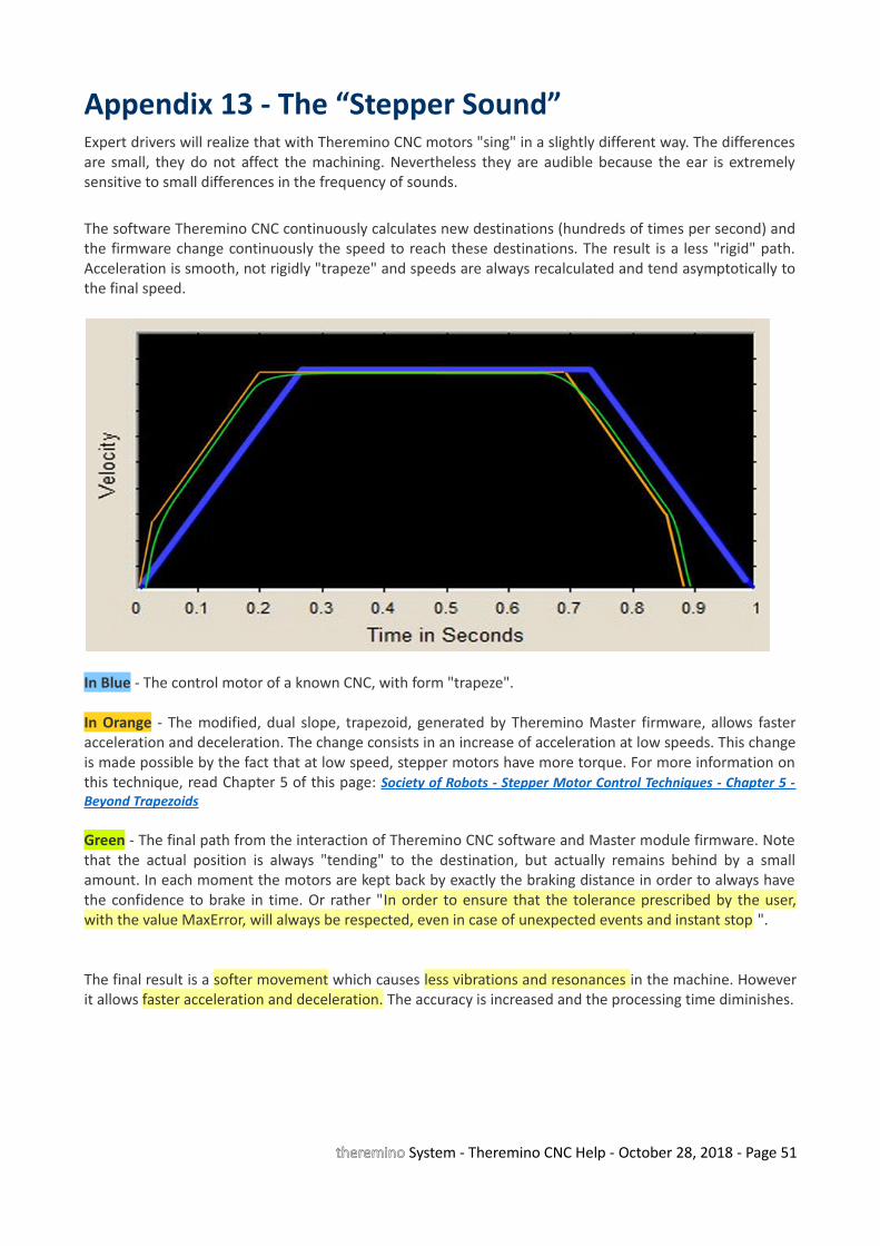
Appendix 13 - The “Stepper Sound”Expert drivers will realize that with Theremino CNC motors "sing" in a slightly different way. The differencesare small, they do not affect the machining. Nevertheless they are audible because the ear is extremelysensitive to small differences in the frequency of sounds.
The software Theremino CNC continuously calculates new destinations (hundreds of times per second) andthe firmware change continuously the speed to reach these destinations. The result is a less "rigid" path.Acceleration is smooth, not rigidly "trapeze" and speeds are always recalculated and tend asymptotically tothe final speed.
In Blue - The control motor of a known CNC, with form "trapeze".
In Orange - The modified, dual slope, trapezoid, generated by Theremino Master firmware, allows fasteracceleration and deceleration. The change consists in an increase of acceleration at low speeds. This changeis made possible by the fact that at low speed, stepper motors have more torque. For more information onthis technique, read Chapter 5 of this page: Society of Robots - Stepper Motor Control Techniques - Chapter 5 -Beyond Trapezoids
Green - The final path from the interaction of Theremino CNC software and Master module firmware. Notethat the actual position is always "tending" to the destination, but actually remains behind by a smallamount. In each moment the motors are kept back by exactly the braking distance in order to always havethe confidence to brake in time. Or rather "In order to ensure that the tolerance prescribed by the user,with the value MaxError, will always be respected, even in case of unexpected events and instant stop ".
The final result is a softer movement which causes less vibrations and resonances in the machine. Howeverit allows faster acceleration and deceleration. The accuracy is increased and the processing time diminishes.
theremino System - Theremino CNC Help - October 28, 2018 - Page 51
Appendix 14 - Double coordinates
The term "Double coordinates" means: "the machine coordinate" and "work piece coordinates." Somedrivers are so accustomed to seeing the cutter going to “home position” at start up, that consider thisoperation obvious and have not ever wondered if they are actually using the machine coordinates.
We have thought a lot and it turned out that only machines that make production (doing the same pieceevery day) and have an accurate piece loader can take advantage of the machine zero. But none of us willconnect Theremino CNC to these machines that cost more than 50,000 Euros. In fact we take theopportunity to remind that the big professional machines can be dangerous and require certifications andlegal guarantees. In this document we always refer to simple machines, without automatic mechanisms andquite slow, intrinsically safe.
- - - - -
Whereby in Theremino CNC there is no zero machine and neither a second coordinate system. Thissimplifies everything:
Take for example the processing of a piece starting from a reference, which indicates the part zero:
With double coordinates :• You will reset the machine coordinates by starting the reset procedure.• Moves with the JOG to the point of reference• Read the numbers shown, for example, X =Y = Z = 234.05 137.00 05.15• Write the three numbers X =Y = Z = 234.95 137.00 05.15 in Gcode• Press Start. And since the X was 234.05 and not 234.95, throw away the piece
One Coordinate :• Moves with the JOG to the point of reference• Reset axes• Press Start
Take for example, measuring the distance between two points:
With double coordinates it does so:• Go to the first point• Read the coordinates (distances from the machine zero)• Write the coordinates, for example X = Y = 234.05 137.00• Go to the second point• Read the coordinates (distances from the machine zero), for example X = Y = 244.05 157.00• Calculate for each axes and you get X = 20 mm Y = 20 mm
Coordinate with each:• Go to the first point• Resets• Go to the second point• Read the result: X = 20 mm Y = 20 mm
theremino System - Theremino CNC Help - October 28, 2018 - Page 52
Appendix 15 - Settings to zeroZ ZeroThe work piece zero in Z axes is done with thickness gauge, feeling when it gets hard enough, this method isvery accurate, better than optical control with side camera. The accuracy is better than a tenth of mm. Butjust move ten centimeters in X or Y axes and vertical alignment is no longer safe (the pieces themselves arenot perfectly planar, the cutter itself is not perfectly orthogonal, we are not at Ferrari or at NASA, but in thelaboratory of a hobbyist). So the part zero must be done every time you change the piece. A zero piecedone far away from the piece is not valid. Even if you tight the piece, this operation can move it in asignificant amount.
A good way to do zeroing Z, is to use the automatic "Z Calibrate with probe", explained in the instructions ofthe panel "Calibrations".
X and Y ZeroThis is done quite easy, with the camera placed at 45 degrees, very close with high zoom. Another goodmethod is to look closely, with eyepiece that magnifies a lot (for example the eyepiece of an old projector).Approaching the tip very close to the surface and focuses a point with the JOG (precision CTRL-JOG). Thenyou get off the tip of two tenths, with CTRL-PageDown, go up with CTRL-PageUp, and check that the notchis centered.
Many times it is not possible to start from a "raw piece", measuring slightly larger, and then take it toprecise measure. In this case the zero must be done on the piece itself and not from the machine zero.
What is the utility of Z precision ?To peel a layer of precise thickness from a surface. In mechanical machining of pre-machined pieces. Inprinted circuit boards, two-color labels with thin surface layer and in other similar processes. In the PCB thecopper layer is thin and 5 hundredths of a millimeter can be seen very well. If you “eat” little, copper linesremain where they should not remain. If you “eat” too much, the stripped part is too dug, too "rough" andthe edges are jagged and ugly. If you “eat” too much you can also break the tool tip. To do a good job, youhave to reset the Z mid-piece, or the "sacrifice piece" should be taken to plan each time, AFTER it has beenfixed, because even the tighten operation could lead to little deformations.
What is the utility of X / Y precision ?For each operation that has to be done on pre-machined or partially worked pieces. For example punctureson a piece which was formed with the drill but not by other means. For example photoengraving or manualoperations on a container.
The X / Y zero should be remade for each clone flanked horizontally and vertically. This is because the zero,made in the lower left corner of the first piece, is not quite accurate for the last piece in upper right corner,and the holes would be visibly moved.
theremino System - Theremino CNC Help - October 28, 2018 - Page 53
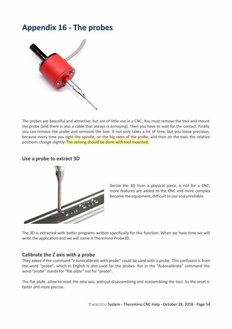
Appendix 16 - The probes
The probes are beautiful and attractive, but are of little use in a CNC. You must remove the tool and mountthe probe (and there is also a cable that always is annoying). Then you have to wait for the contact. Finallyyou can remove the probe and remount the tool. It not only takes a lot of time, but you loose precision,because every time you tight the spindle, on the big stem of the probe, and then on the tool, the relativepositions change slightly. The zeroing should be done with tool mounted.
Use a probe to extract 3D
Derive the 3D from a physical piece, is not for a CNC,more features are added to the CNC and more complexbecome the equipment, difficult to use and unreliable.
The 3D is extracted with better programs written specifically for this function. When we have time we willwrite the application and we will name it Theremino Probe3D.
Calibrate the Z axis with a probeThey asked if the command "z Autocalibrate with probe" could be used with a probe. This confusion is fromthe word "probe", which in English is also used for the probes. But in the "Autocalibrate" command theword "probe" stands for "flat plate" not for "probe".
The flat plate, allow to reset the zeta axis, without disassembling and reassembling the tool. So the reset isfaster and more precise.
theremino System - Theremino CNC Help - October 28, 2018 - Page 54
Appendix 17 - Interpolation in 5 dimensions vectorsTheremino CNC just runs the GCode. If in GCode it is written "B30" then it writes the value 30 in the Slotcorresponding to axis B . If then reads "B40", it interpolates in coordination with the other axes up to 40.Whether these values are right or wrong, or whether they are degrees or something different, it does notmatter for the CNC. It does not matter if the unit is mm or degrees, just interpolate all in 3, 4 or 5dimensions.
In other words the only important thing is that the speed of each axis is calculated in the multidimensionalspace, so that they all arrive to the destination at the same time. For arcs (G02 and G03) there is noproblem because the same GCode limits them to two dimensions (Note 1)
In well designed software the functions are split in layers: CAD - CAM - CNC - HAL. If one of the layers beginto do the work of others, it messes up the whole architecture.
CAD - Design in 3D. 3D visualization with every tool (mechanical annotations, dimensions etc ...)
CAM - Transformation of the 3D tool path (taking into account the dimensions of the tools, the size of thework piece, any possible "interference", the mechanical characteristics of the machine, width compensationtool, route optimization, speed of feed, strategies processing ...)
CNC - Pure execution of the route (none knowledge of how the tool or the work piece are made, because ofthis no interference control nor compensation). "Wire frame" type display of the tool center path (nomachined surfaces).
HAL - Transformation of numbers in hardware movements, taking into account step per millimeter etc ...(the Mach3 motor panel or the HAL system Theremino)
(Note 1) An important aspect which has to be considered is that if you really want to work with 3, 4 or 5 simultaneousaxes you can not use the circular interpolation G02 and G03. The circular interpolations G02 and G03 always work ontwo axes (X / Y, X / Z or Y / Z) and the other axes are still during the interpolation (function indexed). Instead, the G00and G01, can move all five axes together, just write G01 Xnn Ynn ZNN Ann Bnn. This was one of the reasons why wewanted to eliminate G02 and G03
theremino System - Theremino CNC Help - October 28, 2018 - Page 55
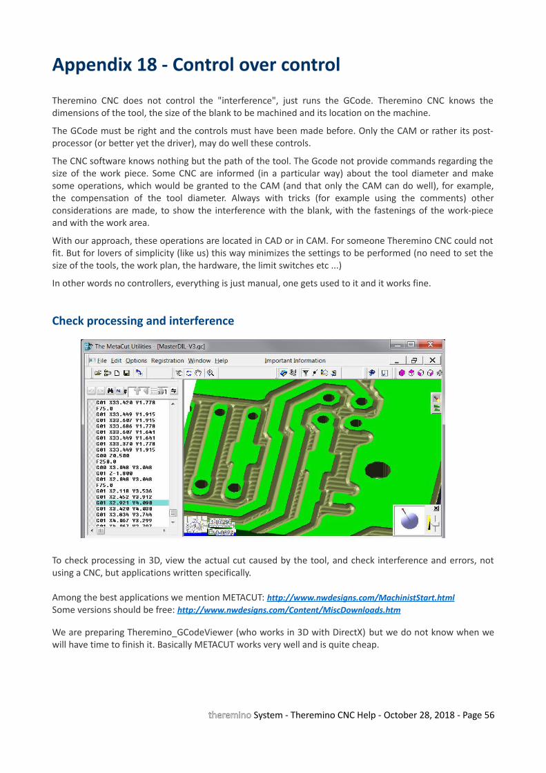
Appendix 18 - Control over control
Theremino CNC does not control the "interference", just runs the GCode. Theremino CNC knows thedimensions of the tool, the size of the blank to be machined and its location on the machine.
The GCode must be right and the controls must have been made before. Only the CAM or rather its post-processor (or better yet the driver), may do well these controls.
The CNC software knows nothing but the path of the tool. The Gcode not provide commands regarding thesize of the work piece. Some CNC are informed (in a particular way) about the tool diameter and makesome operations, which would be granted to the CAM (and that only the CAM can do well), for example,the compensation of the tool diameter. Always with tricks (for example using the comments) otherconsiderations are made, to show the interference with the blank, with the fastenings of the work-pieceand with the work area.
With our approach, these operations are located in CAD or in CAM. For someone Theremino CNC could notfit. But for lovers of simplicity (like us) this way minimizes the settings to be performed (no need to set thesize of the tools, the work plan, the hardware, the limit switches etc ...)
In other words no controllers, everything is just manual, one gets used to it and it works fine.
Check processing and interference
To check processing in 3D, view the actual cut caused by the tool, and check interference and errors, notusing a CNC, but applications written specifically.
Among the best applications we mention METACUT: http://www.nwdesigns.com/MachinistStart.htmlSome versions should be free: http://www.nwdesigns.com/Content/MiscDownloads.htm
We are preparing Theremino_GCodeViewer (who works in 3D with DirectX) but we do not know when wewill have time to finish it. Basically METACUT works very well and is quite cheap.
theremino System - Theremino CNC Help - October 28, 2018 - Page 56
Appendix 19 - Asynchronous operation
Theremino CNC, as all other Theremino applications, is based on totally asynchronous communications. Fordetails read here: http://www.theremino.com/contacts/the-theremino-mission
In the specific case of CNC, you can identify five independent layers, deliberately NOT synchronous witheach other:
• The application Theremino CNC sends the values of the axes to the Slot every 5 milliseconds.
• The application reads the HAL Slot, turns data in hardware format (Hardware Abstraction) andsends them via the USB system. This process is not synchronous with Theremino CNC, and occursevery one or two milliseconds.
• The numerical values of the axes are read from the firmware layer, at each USB exchange (one ortwo milliseconds)
• The firmware, according to the continuously variable destination, recalculates the displacementparameters exactly once each millisecond, with high precision. To accurately calculate accelerationsand speeds, these calculations are managed by an interrupt handler and therefore areasynchronous, with respect to both USB and Theremino CNC and the STEP of the motors.
• Hardware PWM module produce the STEP to the motors, with skidding of less than 20 nanoseconds (depending on the quartz clock at 48 MHz). Therefore this layer is completely independentand asynchronous with respect to the previous layers.
Many people feel more comfortable with completely deterministic systems and consider inferior, if not"completely wrong", our working principles.http://www.theremino.com/contacts/the-theremino-mission#precision
We do not want to start a discussion about this. Just explain that, though willing it would be impossible totransform the system Theremino in a synchronous system. To do that you should redesign the wholesystem, a new communication protocol with the hardware, Master and Slave firmware modules, much ofHAL (which is really big) and all Input Output Theremino CNC. Finally, you may no longer use the Slot, as weunderstand them now, because the Slots do not include commands, but only numeric values, and nosynchronization mechanism.
A job like this, it could take years, even for us that we designed the system (as it took years to design as it isnow) and still we are not willing to do that, because it would be exactly the opposite direction, compared toour vision : http://www.theremino.com/contacts/the-theremino-mission#inout
With regard to gifts, we remember that our work is totally Nonprofit and we can not do any kind offavoritism. That is, donations are to be totally disconnected from our work. Otherwise they would be not"donations" but "compensation". To explore this topic read here: http://www.theremino.com/contacts/copyrights#donations
theremino System - Theremino CNC Help - October 28, 2018 - Page 57

Appendix 20 - Accuracy of the forward speedThe firmware of the Master controls the motor steps with high precision (variations less then 20 nS) and ensures thatthe variations between one pulse and the next, never exceed the specified acceleration. This ensures that the motorsnever lose steps.
But, since the timing of the advancements is done in real time from an application on the computer, some users haveexpressed concerns, on the speed accuracy and stability. The argument they make is that when the computer is busy itbecomes slower. But by requiring the Windows scheduler a granularity of 1 mS and with a Real-Time thread, we haveobtained a remarkable stability and precision that (according to us) is more than enough for each type of processing. Inthe latest versions of Theremino CNC (from 3.31), we have also added a stabilizer algorithm, which has greatlyimproved precision.
Result test without stabilizer - Speed accuracy: 3% - Wow and Flutter: +/- 1.5%Result test with stabilizer latest version, from 3.31 version- Speed accuracy: 0.5% - Wow and Flutter: +/- 0.2%
Download videos of testhttp://www.theremino.com/files/ThereminoCNC_V3.31_Without_Stabilizer.avihttp://www.theremino.com/files/ThereminoCNC_V3.31_With_Stabilizer.avi
For those wishing to repeat the measurements, the following ZIP files also include test and configuration.http://www.theremino.com/files/ThereminoCNC_SpeedSpectrums.ziphttp://www.theremino.com/files/ThereminoCNC_SpeedSpectrums_Stabilized.zip
Conditions of measurementThe tests have been done with the CPU under load (two CPU from 3 GHz to more than 50%). This was due to the simultaneousexecution of the CNC, the spectrum analyzer DAA, and the program CamStudio to capture video. Without DAA and CamStudio,signals were audibly more stable. This is a safety margin, for the declared characteristics.
Configuration parametersMax Speed(hal) = 900 Max Acc (hal) = 50Steps per mm (hal) = 400 Feed (cnc) = 100 / 300 / 700
CommentsWith stabilizer Wow and Flutter are reduced to levels not audible. If you set low acceleration (for large and heavy machines) valuesof Wow and Flutter also fall below 0.1%. These are excellent results which are valid for any type of processing.
Principle of operation speed stabilizer- Even using a real time Thread, when the Windows scheduler is overloaded it becomes late.- In worst times the loop time increases by a few milliseconds, and it is not possible to stabilize it.- Being not possible to stabilize it, it is better to measure it and compensate by varying the length of the interpolate micro-segments.- This stabilizes the "driving"speed on firmware .. Even without this fix the work would be enough good. But eliminating the "mewling" effect is important because it could give a badimpression.
theremino System - Theremino CNC Help - October 28, 2018 - Page 58

Appendix 21 - Gcode generation for Theremino CNC
With a CAD - CAMIt would be good to create a new post-processor in CAM, name it Theremino CNC, and set it to generate theright codes.
The main things to check in the CAM post-processor :• Using millimeters (Metric mode)• Use absolute coordinates (Absolute mode)• Use only G and M codes listed in the table "Codes implemented"• G02 and G03 are implemented, but we advise not to use them (see the relevant page)
When in doubt, just Load Gcode and check it for invalid codes
With an Eagle project or other editor of printed circuit boards
We recommend Eagle for PCB, with our libraries, and with our "Fast Gcode" post processor which is notexactly a post processor but rather a ULP (User Language Program).
Fast Gcode creates optimized GCode (minimizes the movement) and creates all the PCB examples, like theexamples of Theremino CNC.
http://www.theremino.com/downloads/uncategorized#eagle
theremino System - Theremino CNC Help - October 28, 2018 - Page 59
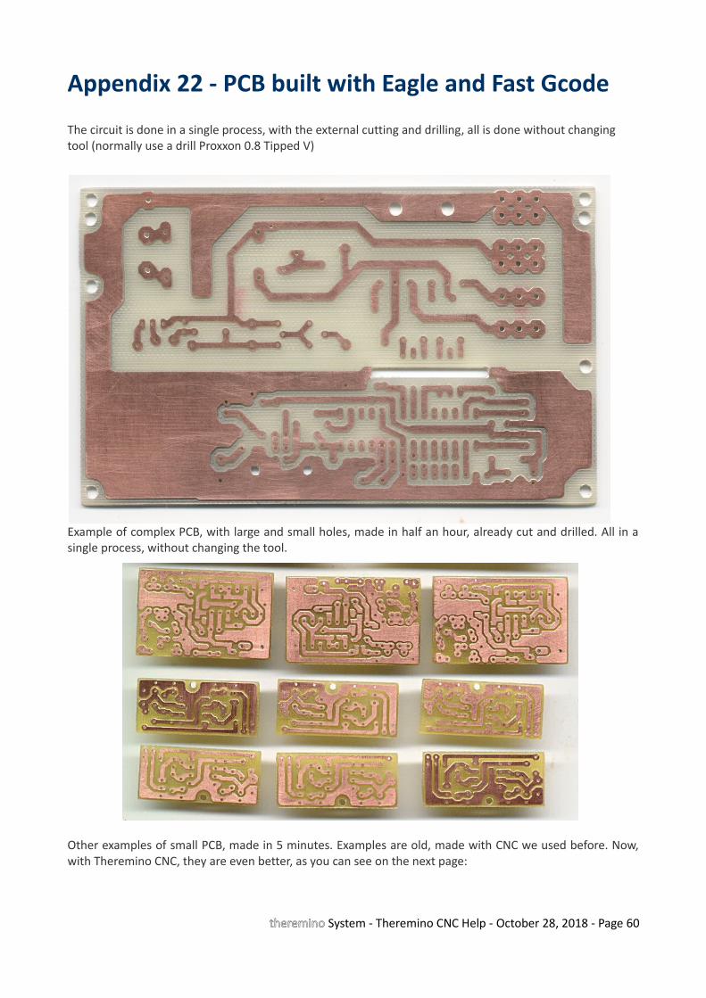
Appendix 22 - PCB built with Eagle and Fast Gcode
The circuit is done in a single process, with the external cutting and drilling, all is done without changing tool (normally use a drill Proxxon 0.8 Tipped V)
Example of complex PCB, with large and small holes, made in half an hour, already cut and drilled. All in asingle process, without changing the tool.
Other examples of small PCB, made in 5 minutes. Examples are old, made with CNC we used before. Now,with Theremino CNC, they are even better, as you can see on the next page:
theremino System - Theremino CNC Help - October 28, 2018 - Page 60
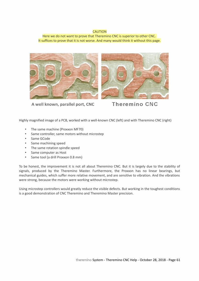
CAUTIONHere we do not want to prove that Theremino CNC is superior to other CNC.
It suffices to prove that it is not worse. And many would think it without this page.
Highly magnified image of a PCB, worked with a well-known CNC (left) and with Theremino CNC (right)
• The same machine (Proxxon MF70)• Same controller, same motors without microstep• Same GCode• Same machining speed• The same rotation spindle speed• Same computer as Host• Same tool (a drill Proxxon 0.8 mm)
To be honest, the improvement it is not all about Theremino CNC. But it is largely due to the stability ofsignals, produced by the Theremino Master. Furthermore, the Proxxon has no linear bearings, butmechanical guides, which suffer more relative movement, and are sensitive to vibration. And the vibrationswere strong, because the motors were working without microstep.
Using microstep controllers would greatly reduce the visible defects. But working in the toughest conditionsis a good demonstration of CNC Theremino and Theremino Master precision.
theremino System - Theremino CNC Help - October 28, 2018 - Page 61
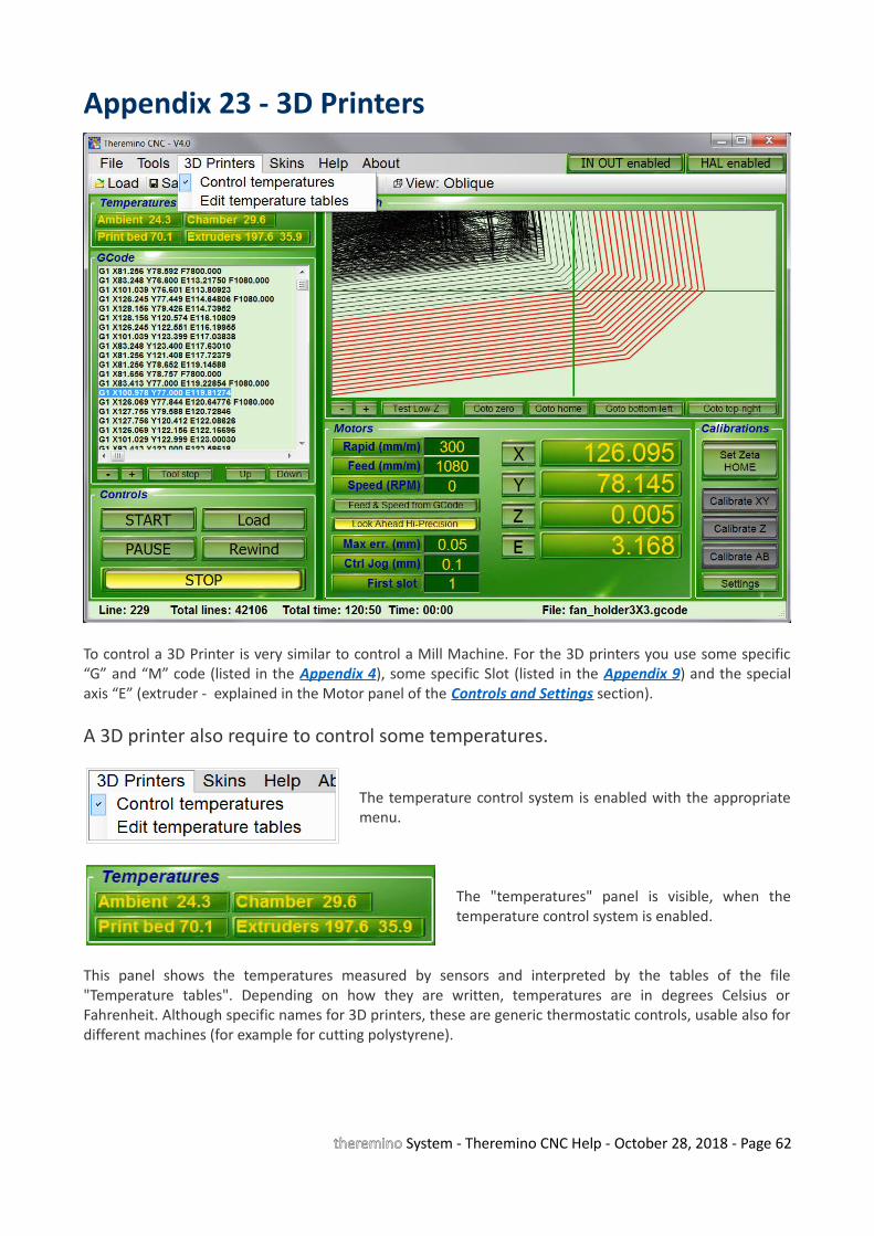
Appendix 23 - 3D Printers
To control a 3D Printer is very similar to control a Mill Machine. For the 3D printers you use some specific“G” and “M” code (listed in the Appendix 4), some specific Slot (listed in the Appendix 9) and the specialaxis “E” (extruder - explained in the Motor panel of the Controls and Settings section).
A 3D printer also require to control some temperatures.
The temperature control system is enabled with the appropriatemenu.
The "temperatures" panel is visible, when thetemperature control system is enabled.
This panel shows the temperatures measured by sensors and interpreted by the tables of the file"Temperature tables". Depending on how they are written, temperatures are in degrees Celsius orFahrenheit. Although specific names for 3D printers, these are generic thermostatic controls, usable also fordifferent machines (for example for cutting polystyrene).
theremino System - Theremino CNC Help - October 28, 2018 - Page 62
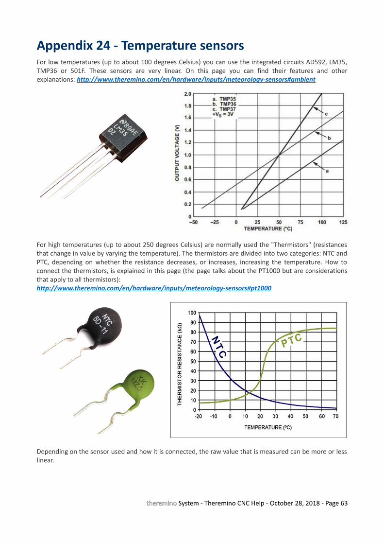
Appendix 24 - Temperature sensorsFor low temperatures (up to about 100 degrees Celsius) you can use the integrated circuits AD592, LM35,TMP36 or 501F. These sensors are very linear. On this page you can find their features and otherexplanations: http://www.theremino.com/en/hardware/inputs/meteorology-sensors#ambient
For high temperatures (up to about 250 degrees Celsius) are normally used the "Thermistors" (resistancesthat change in value by varying the temperature). The thermistors are divided into two categories: NTC andPTC, depending on whether the resistance decreases, or increases, increasing the temperature. How toconnect the thermistors, is explained in this page (the page talks about the PT1000 but are considerationsthat apply to all thermistors):http://www.theremino.com/en/hardware/inputs/meteorology-sensors#pt1000
Depending on the sensor used and how it is connected, the raw value that is measured can be more or lesslinear.
theremino System - Theremino CNC Help - October 28, 2018 - Page 63
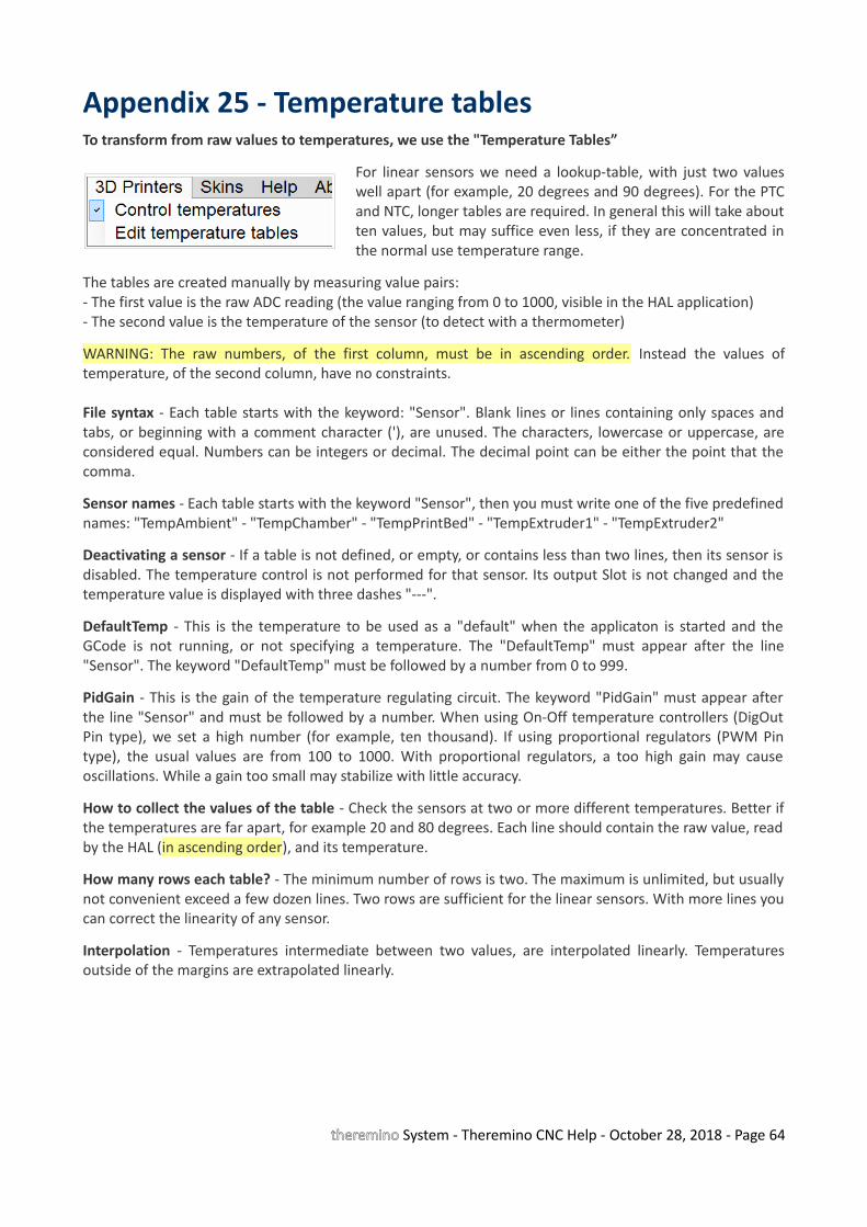
Appendix 25 - Temperature tablesTo transform from raw values to temperatures, we use the "Temperature Tables”
For linear sensors we need a lookup-table, with just two valueswell apart (for example, 20 degrees and 90 degrees). For the PTCand NTC, longer tables are required. In general this will take aboutten values, but may suffice even less, if they are concentrated inthe normal use temperature range.
The tables are created manually by measuring value pairs:- The first value is the raw ADC reading (the value ranging from 0 to 1000, visible in the HAL application)- The second value is the temperature of the sensor (to detect with a thermometer)
WARNING: The raw numbers, of the first column, must be in ascending order. Instead the values oftemperature, of the second column, have no constraints.
File syntax - Each table starts with the keyword: "Sensor". Blank lines or lines containing only spaces andtabs, or beginning with a comment character ('), are unused. The characters, lowercase or uppercase, areconsidered equal. Numbers can be integers or decimal. The decimal point can be either the point that thecomma.
Sensor names - Each table starts with the keyword "Sensor", then you must write one of the five predefinednames: "TempAmbient" - "TempChamber" - "TempPrintBed" - "TempExtruder1" - "TempExtruder2"
Deactivating a sensor - If a table is not defined, or empty, or contains less than two lines, then its sensor isdisabled. The temperature control is not performed for that sensor. Its output Slot is not changed and thetemperature value is displayed with three dashes "---".
DefaultTemp - This is the temperature to be used as a "default" when the applicaton is started and theGCode is not running, or not specifying a temperature. The "DefaultTemp" must appear after the line"Sensor". The keyword "DefaultTemp" must be followed by a number from 0 to 999.
PidGain - This is the gain of the temperature regulating circuit. The keyword "PidGain" must appear afterthe line "Sensor" and must be followed by a number. When using On-Off temperature controllers (DigOutPin type), we set a high number (for example, ten thousand). If using proportional regulators (PWM Pintype), the usual values are from 100 to 1000. With proportional regulators, a too high gain may causeoscillations. While a gain too small may stabilize with little accuracy.
How to collect the values of the table - Check the sensors at two or more different temperatures. Better ifthe temperatures are far apart, for example 20 and 80 degrees. Each line should contain the raw value, readby the HAL (in ascending order), and its temperature.
How many rows each table? - The minimum number of rows is two. The maximum is unlimited, but usuallynot convenient exceed a few dozen lines. Two rows are sufficient for the linear sensors. With more lines youcan correct the linearity of any sensor.
Interpolation - Temperatures intermediate between two values, are interpolated linearly. Temperaturesoutside of the margins are extrapolated linearly.
theremino System - Theremino CNC Help - October 28, 2018 - Page 64
Examples of temperature tablesThe values of the following examples have been calculated starting from the theoretical characteristics ofthe sensors. The precision should be within a fraction of a degree. To obtain a more precise calibration, youwill have to slightly touch up the values.
This is an example of a complete table, which reads the temperature of the air inside the chamber. Thetemperature values are calculated for a sensor LM35.'========================= Sensor TempChamber DefaultTemp 20 PidGain 100'========================='HAL_Value Temperature'------------------------- 0 0 455 150
Values calculated for a sensor LM35, powered at 5 Volts.
'HAL_Value Temperature'------------------------- 0 0 455 150
Values calculated for a sensor TMP36, powered at 5 Volts.
'HAL_Value Temperature'------------------------- 15 -50 530 125
Values calculated for a sensor 501F, powered at 5 Volts.
'HAL_Value Temperature'------------------------- 43.3 0 303 60
Values calculated for a sensor AD592, powered at 5 Volts, with a 8.2k resistor from output to ground.
'HAL_Value Temperature'------------------------- 678.4 0 939.3 125
The following example was used with an NTC thermistor, connected with a resistor to 3.3 volts.For thermistors you can not use these values, but you will have to write specific tables for each sensor.Note that the values of the left column should always be growing.
'HAL_Value Temperature'------------------------- 87 250 122 200 176 150 312 100 560 50
theremino System - Theremino CNC Help - October 28, 2018 - Page 65

Appendix 26 - Low accelerations compensationNormally the stepper motors acceleration (Acc.max parameter in the HAL application), is adjusted aboutone-tenth of the maximum speed (Vel.max parameter, always in the HAL). In these conditions, theacceleration time is negligible and has minimal effect on the tool path.
But the machines with small engines and heavy trucks need very low accelerations, sometimes even lessthan a hundredth of the maximum speed. In these cases, the acceleration time becomes longer, comparedto that calculated and displayed in the status bar of the application, also the engine that has to do moreroad arrives late and the tool path differs from the ideal one. The movements broken into small segmentsand the horizontal, vertical movements and to 45 degrees are not affected by this defect. But in some cases,with intermediate slopes, errors can also get to a few millimeters.
In this and the following images you see the path errors on"Test_LowAccCorrector.gc", setting a very low acceleration,Acc.max = 5 and Vel.max = 700.
In these conditions the errors (distance between the redand the black line) are approximately one millimeter and insome points exceeding it.
The running time is 8 seconds, in large part caused by thelow acceleration of the motors.
In this second picture we see the effect of the option"Compensate acceleration effects".
The errors are limited to three tenths of a millimeter, setting"Max err. (Mm) = 0.3 ".
With this accuracy the running time increases slightly andwent from eight to nine seconds.
In this image we see the effect of the option "Compensateacceleration effects" with errors limited to one-tenth of amillimeter, with "Max err. (Mm) = 0.1 ".
In this case the running time is increased from eight totwelve seconds.
Further reducing the "Max err. (mm)" parameter, a greateraccuracy is obtained, at the expense of a progressivelylonger time. With five cens of a millimeter the timeincreases to 14 seconds and with three cents to 17 seconds.
It is advisable to do experiments and not to exaggerate the precision so as not to increase times too much.
Using "Look ahead" with low values of "Max err" and with an optimum advancement speed, thiscompensation is not necessary. Therefore enable it only as a quick and brutal solution.
theremino System - Theremino CNC Help - October 28, 2018 - Page 66