thermal power division, montreal, canada - board of commissioners
TRANSCRIPT
FEASIBILITY STUDY OF HTGS UNITS 1&2 CONVERSION TO SYNCHRONOUS CONDENSER - AN EVALUATION OF RUN UP OPTIONS FOR GENERATORS
THERMAL POWER DIVISION, MONTREAL, CANADA
NALCOR
ORIGINAL
REPORT
Contract No. 503743
Revision 02
February 2011
Muskrat Falls Project - CE-56 Rev. 1 (Public) Page 1 of 51

Thermal Power Holyrood Synchronous Condenseur Study 503743
NALCOR
FEASIBILITY STUDY OF HTGS UNITS 1&2 CONVERSION TO
SYNCHRONOUS CONDENSER - AN EVALUATION OF RUN UP OPTIONS
FOR GENERATORS
REPORT
REVISION 02
SNC-LAVALIN Thermal Power
February 2011
Muskrat Falls Project - CE-56 Rev. 1 (Public) Page 2 of 51
Muskrat Falls Project - CE-56 Rev. 1 (Public) Page 3 of 51
Thermal Power ii
© 2011 SNC-Lavalin Inc. All rights reserved - Confidential
Holyrood Synchronous Condenser Study 503743 - Rev. 02
TABLE OF CONTENTS
EXECUTIVE SUMMARY
1.0 INTRODUCTION AND MANDATE................................................................................1-2
2.0 TECHNOLOGY REVIEW...............................................................................................2-1 2.1 Unit 3 Existing System (Option 1) ......................................................................2-2 2.2 Motor Drive with Magnetic Coupling (Option 2)..................................................2-3 2.3 Motor Drive with Hydraulic Coupling (Option 3) .................................................2-5 2.4 Variable Speed Drive with Overrunning Clutch (Option 4A, 4B) ........................2-6 2.5 Static Frequency Converter Generator Start(Option 5).....................................2-7
3.0 RFP AND BUDGETARY PROPOSALS RECEIVED ....................................................3-1 3.1 Acceleration Skids..............................................................................................3-1 3.2 Static Start Units.................................................................................................3-2 3.3 Other Potential Suppliers for Static Start Units ..................................................3-2
4.0 ADVANTAGES AND DISADVANTAGES OF TECHNOLOGY OPTIONS ...................4-1
5.0 MODIFICATIONS REQUIRED TO UNITS 1 & 2 GENERATOR ROTORS...................5-1 5.1 Available Space Footprint Behind Generator Exciter .........................................5-1 5.2 Decoupling Generator From Steam Turbine ......................................................5-2 5.3 Installation of Generator Thrust Bearing ............................................................5-3 5.4 Barring System...................................................................................................5-3 5.5 Conversion Process ...........................................................................................5-4 5.6 Auxiliary Systems...............................................................................................5-4
6.0 BUDGETARY EQUIPMENT COSTS.............................................................................6-1
7.0 RECOMMENDATION FOR TECHNOLOGY .................................................................7-1 7.1 Recommendation ...............................................................................................7-1 7.2 Single Line Diagram (SLD).................................................................................7-2 7.3 Proposed Equipment Location ...........................................................................7-2
8.0 COST ESTIMATE FOR RECOMMENDED OPTION.....................................................8-1 8.1 Direct Costs........................................................................................................8-1 8.2 Indirect Costs .....................................................................................................8-1 8.3 Exclusions ..........................................................................................................8-2 8.4 Alternative Configuration ....................................................................................8-4 8.5 Estimate Accuracy..............................................................................................8-4
9.0 PRELIMINARY PROJECT SCHEDULE........................................................................9-1
10.0 ITEMS TO BE INCLUDED IN NEXT PHASE..............................................................10-1
Muskrat Falls Project - CE-56 Rev. 1 (Public) Page 4 of 51

Thermal Power iii
© 2011 SNC-Lavalin Inc. All rights reserved - Confidential
Holyrood Synchronous Condenser Study 503743 - Rev. 02
FIGURE LIST
Figure 1 Photograph of unit 3 acceleration skid PGC model HL60/9HS ...................................2-2 Figure 2 Illustration of unit in housing....................................................2-4 Figure 3 Side view of typical coupling....................................................................2-4 Figure 4 hydraulic torque converter starter skid model ..........................................2-5 Figure 5 arrangement ................................................................................2-5 Figure 6 Pony motor c/w step-up gearbox & over-running clutch (typical) ................................2-6 Figure 7 A typical 4.16 kV adjustable speed drive (Eaton)........................................................2-6 Figure 8 Typical Static Start Unit with incoming disconnect/contactor
and transformer ..........................................................................2-10 Figure 9 Typical Static Start Unit from ...........................................................................2-11 Figure 10 Typical Static Start Unit from ....................2-11 Figure 11 Exciter housing, rear of generator, unit 2 ....................................................................5-1 Figure 12 View of space available behind unit 2 .........................................................................5-2 Figure 13 Sketch of generator/turbine coupling as provide by GE ..............................................5-3
APPENDIX LIST
Appendix A Equipment List for all Options
Appendix B Budget Costing for all Options
Appendix C Rotor Inertia
Appendix D Single Line Diagrams
Appendix E General Layout and Alternative Layouts for Excitation System
Appendix F Quotes from Static Start Unit Suppliers E
Appendix G Preliminary Project Schedule
Muskrat Falls Project - CE-56 Rev. 1 (Public) Page 5 of 51
Thermal Power 1-1 © 2011 SNC-Lavalin Inc.
All rights reserved - Confidential
Holyrood Synchronous Condenser Study 503743 - Rev. 02
EXECUTIVE SUMMARY
SNC-Lavalin (SLI) received a mandate from NALCOR to prepare a study of the modifications necessary to allow Holyrood units 1 & 2 to operate as synchronous condensers in anticipation of implementation of the Lower Churchill Hydroelectric Project. Since Holyrood would also be required to provide generation for several years to come during the winter period, the machines would have the flexibility to operate either as synchronous condensers or in generation mode (as unit 3).
SLI carried out a review of proven modern technology available for starting the machines as synchronous condensers and accelerating them to synchronous speed. Available options included electric motor drives at either constant or variable speed with various coupling arrangements, and variable speed drives acting directly on the generator stator.
Since both units 1 & 2 were to be modified, and NALCOR expressed interest in modernizing the drive system currently used on unit 3, a system using two static starter systems was recommended. Each system could be used to start any of the three machines, and the provision of two systems gives the necessary redundancy. The static starters would require new excitation transformers as well as integration with the existing excitation, control, and protection systems.
Each generator must be de-coupled from the steam turbine, and a new stub shaft is required at the outboard end of the generator to locate a new thrust bearing and turning gear assembly. During operation as a generator, either the stub shaft could be removed, or the thrust pads of the new thrust bearing would be removed. It is not completely clear that the main shaft coupling provides sufficient clearance for synchronous condenser operation. A detailed inspection of one of the couplings is required to confirm this point, as GE have not seen fit to confirm the coupling details.
Preliminary equipment arrangement drawings and single line diagrams have been prepared. Budgetary prices were received from qualified international suppliers for all major items.
A capital cost estimate has been prepared indicating an estimated installed cost of approximately $5,748,000. This cost includes an allowance for inflation through 2014 and a contingency for items which cannot be defined at this stage. The estimate meets AACE class 4 definitions and accuracy.
Muskrat Falls Project - CE-56 Rev. 1 (Public) Page 6 of 51
Thermal Power 1-2 © 2011 SNC-Lavalin Inc.
All rights reserved - Confidential
Holyrood Synchronous Condenser Study 503743 - Rev. 02
1.0 INTRODUCTION AND MANDATE
SNC-Lavalin Thermal Power was mandated to prepare a screening study and cost estimate for the implementation of the capability of operating as synchronous condensers for generators 1 and 2 at the NALCOR Holyrood generating station. These two machines have a rating of 194,445 kVA (PF 0.90) and were supplied by General Electric Canada.
Holyrood is an active generating station in the winter months, but remains largely unused in the summer, and NALCOR is considering using units 1 and 2 more effectively. Once phase 1 of the Lower Churchill power generation project is completed, Holyrood would be converted from a generating station to synchronous condenser operation.
A team from SNC-Lavalin Thermal Power (Montreal) visited the Holyrood GS on August 5/6 2010 and met with members of the plant staff and NALCOR Engineering in St. John’s.
The SNCL team has proceeded to investigate the technical and commercial implications of adapting units 1 and 2 to operate synchronous condensers while maintaining the capability to operate in generation mode.
One intermediate progress report presentation was made by SNC-Lavalin personnel to NALCOR staff in St. John’s. The final meeting where the major results of the study were presented to NALCOR staff was held in St. John’s on October 26th, 2010.
This report presents the detailed findings including both technical and cost comparisons, and provides a recommendation for the type of equipment optimally suited for the conversion to synchronous condenser operation at Holyrood.
Muskrat Falls Project - CE-56 Rev. 1 (Public) Page 7 of 51
Thermal Power 2-1 © 2011 SNC-Lavalin Inc.
All rights reserved - Confidential
Holyrood Synchronous Condenser Study 503743 - Rev. 02
2.0 TECHNOLOGY REVIEW
The existing unit 3 generator utilizes a pony motor acceleration system and is decoupled from the steam turbine once per year and re-coupled once per year for the generating season (winter). This conversion operation takes approximately 15 days, during which time the unit is not operational.
Units 1 and 2 require an acceleration system to bring the uncoupled generator to synchronous speed for synchronous condenser operation plus decoupling the generator from the steam turbine. Provision of a thrust bearing is also required.
The installation of an overrunning clutch between the steam turbine and generator for units 1 and 2 is not feasible due to insufficient space for installation. Creating the necessary space would only have been possible if the generator was moved axially on its foundation, which was not considered.
Several types of generator acceleration systems are available, including various types of acceleration drives (skidded) connected to the decoupled generator using either constant speed or VFD drive, or a static frequency drive acting directly on the generator stator.
Note that whichever type of generator acceleration system is ultimately selected, the steam turbine/generator lube oil system and generator cooling system will need to remain operational. The existing systems may require a small low-power bypass circulation system installed that would operate only during the reduced cooling and lube oil needs of synchronous condenser operation.
SNC-Lavalin identified five different types of acceleration or starting systems for review, which are described in more detail in the following sections.
SNC-L was informed that a spare medium voltage circuit breaker was available on each unit board for synchronous condenser auxiliaries. In synchronous condenser mode the large drives used in the generating mode such as cooling water pumps and boiler feed pumps will not be operating. In the synchronous condenser mode, the station service load will be much less than at present when operating in the generating mode. However, for the static start option the excitation system has to be fed from the medium voltage bus. Since the units still will have to operate in the generating mode for some years the excitation system load is fed from the medium voltage bus It was confirmed the capacity of the bus is sufficient to cover the excitation load.
Muskrat Falls Project - CE-56 Rev. 1 (Public) Page 8 of 51
Thermal Power 2-2 © 2011 SNC-Lavalin Inc.
All rights reserved - Confidential
Holyrood Synchronous Condenser Study 503743 - Rev. 02
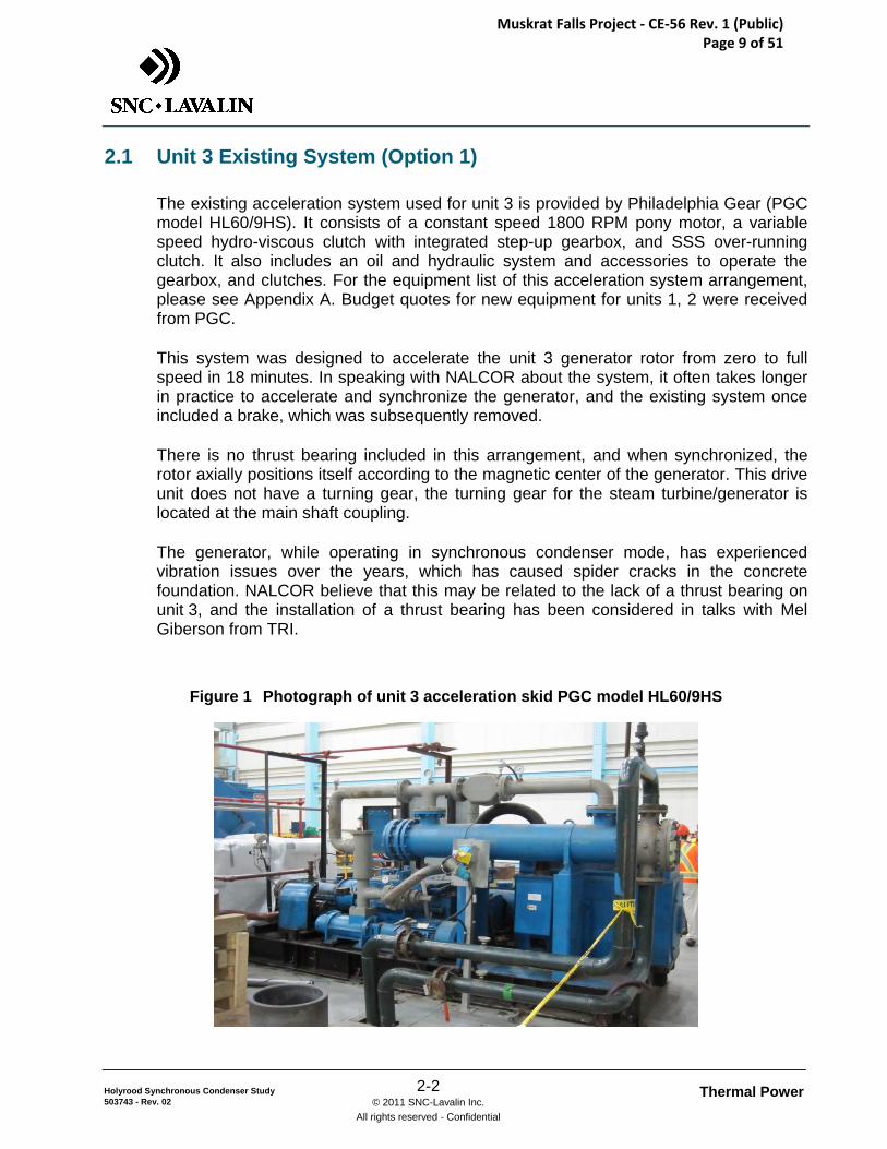
2.1 Unit 3 Existing System (Option 1)
The existing acceleration system used for unit 3 is provided by Philadelphia Gear (PGC model HL60/9HS). It consists of a constant speed 1800 RPM pony motor, a variable speed hydro-viscous clutch with integrated step-up gearbox, and SSS over-running clutch. It also includes an oil and hydraulic system and accessories to operate the gearbox, and clutches. For the equipment list of this acceleration system arrangement, please see Appendix A. Budget quotes for new equipment for units 1, 2 were received from PGC.
This system was designed to accelerate the unit 3 generator rotor from zero to full speed in 18 minutes. In speaking with NALCOR about the system, it often takes longer in practice to accelerate and synchronize the generator, and the existing system once included a brake, which was subsequently removed.
There is no thrust bearing included in this arrangement, and when synchronized, the rotor axially positions itself according to the magnetic center of the generator. This drive unit does not have a turning gear, the turning gear for the steam turbine/generator is located at the main shaft coupling.
The generator, while operating in synchronous condenser mode, has experienced vibration issues over the years, which has caused spider cracks in the concrete foundation. NALCOR believe that this may be related to the lack of a thrust bearing on unit 3, and the installation of a thrust bearing has been considered in talks with Mel Giberson from TRI.
Figure 1 Photograph of unit 3 acceleration skid PGC model HL60/9HS
Muskrat Falls Project - CE-56 Rev. 1 (Public) Page 9 of 51
Thermal Power 2-3 © 2011 SNC-Lavalin Inc.
All rights reserved - Confidential
Holyrood Synchronous Condenser Study 503743 - Rev. 02
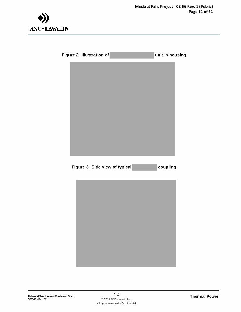
2.2 Motor Drive with Magnetic Coupling (Option 2)
This acceleration system consists primarily of a drive-train including a generator main thrust bearing, an over-running clutch, a step-up gearbox, a magnetic coupling and a constant speed pony motor. For the budgetary equipment list of this acceleration system, please see Appendix A.
For this study, a unit supplied by a leader in this technology was considered. The largest coupling available is rated 1750 HP at 1800 RPM (a maximum rating of only 275 HP is available at 3600 RPM), therefore a step-up gearbox is required in this arrangement. This unit requires water cooling.
Muskrat Falls Project - CE-56 Rev. 1 (Public) Page 10 of 51
Thermal Power 2-4 © 2011 SNC-Lavalin Inc.
All rights reserved - Confidential
Holyrood Synchronous Condenser Study 503743 - Rev. 02
Figure 2 Illustration of unit in housing
Figure 3 Side view of typical coupling
Muskrat Falls Project - CE-56 Rev. 1 (Public) Page 11 of 51
Thermal Power 2-5 © 2011 SNC-Lavalin Inc.
All rights reserved - Confidential
Holyrood Synchronous Condenser Study 503743 - Rev. 02
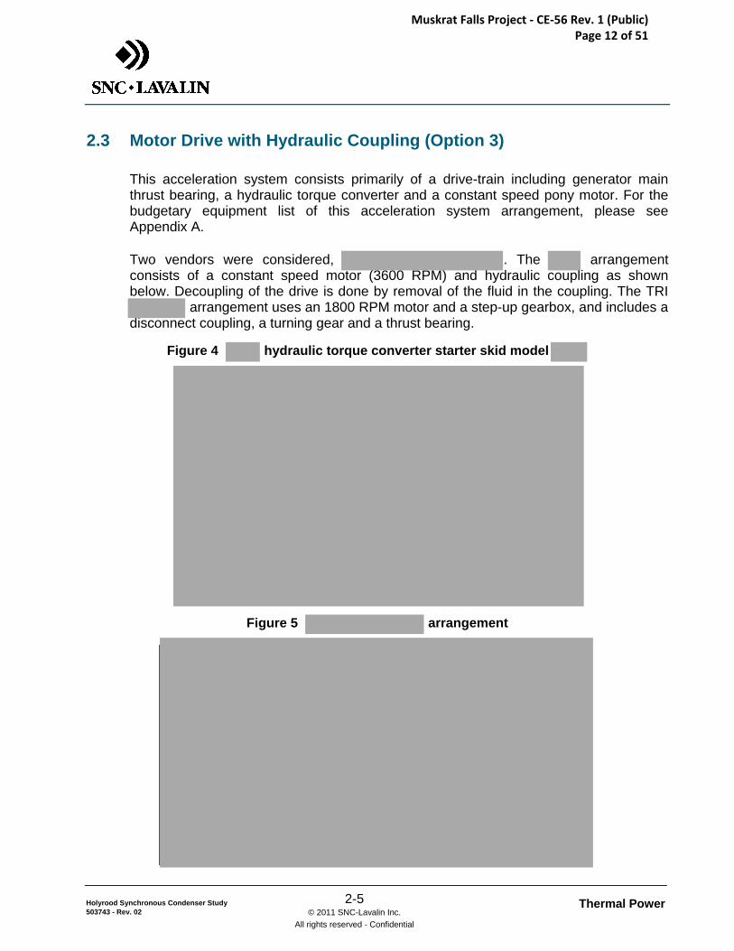
2.3 Motor Drive with Hydraulic Coupling (Option 3)
This acceleration system consists primarily of a drive-train including generator main thrust bearing, a hydraulic torque converter and a constant speed pony motor. For the budgetary equipment list of this acceleration system arrangement, please see Appendix A.
Two vendors were considered, . The arrangement consists of a constant speed motor (3600 RPM) and hydraulic coupling as shown below. Decoupling of the drive is done by removal of the fluid in the coupling. The TRI
arrangement uses an 1800 RPM motor and a step-up gearbox, and includes a disconnect coupling, a turning gear and a thrust bearing.
Figure 4 hydraulic torque converter starter skid model
Figure 5 arrangement
Muskrat Falls Project - CE-56 Rev. 1 (Public) Page 12 of 51
Thermal Power 2-6 © 2011 SNC-Lavalin Inc.
All rights reserved - Confidential
Holyrood Synchronous Condenser Study 503743 - Rev. 02
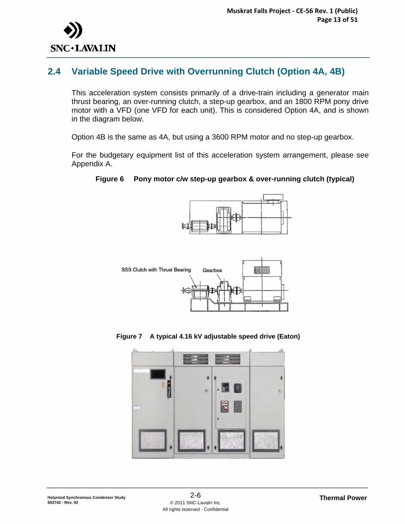
2.4 Variable Speed Drive with Overrunning Clutch (Option 4A, 4B)
This acceleration system consists primarily of a drive-train including a generator main thrust bearing, an over-running clutch, a step-up gearbox, and an 1800 RPM pony drive motor with a VFD (one VFD for each unit). This is considered Option 4A, and is shown in the diagram below.
Option 4B is the same as 4A, but using a 3600 RPM motor and no step-up gearbox.
For the budgetary equipment list of this acceleration system arrangement, please see Appendix A.
Figure 6 Pony motor c/w step-up gearbox & over-running clutch (typical)
Figure 7 A typical 4.16 kV adjustable speed drive (Eaton)
Muskrat Falls Project - CE-56 Rev. 1 (Public) Page 13 of 51
Thermal Power 2-7 © 2011 SNC-Lavalin Inc.
All rights reserved - Confidential
Holyrood Synchronous Condenser Study 503743 - Rev. 02
2.5 Static Frequency Converter Generator Start(Option 5)
2.5.1 System Description
A static frequency converter (SFC) start system is connected to the generator which is soft started as a synchronous motor. The SFC is disconnected just before the generator is synchronized for a bumpless transfer to the grid.
With this option one SFC can be used to start one or more units by switching the output to the unit being started using additional switches/contactors. However, for reliability reasons redundancy is recommended so that one SFC should be supplied for each unit with the ability to start either unit from either SFC. If, in the future, it is decided to convert unit 3 to the same system, the two SFCs could be connected to unit 3.
Available SFC technologies such as Load commutated inverter (LCI) or Voltage Source Inverter (VSI) units are selected by suppliers based on their assessment of alternatives, previous experience and cost.
All drive alternatives typically comprise an incoming breaker or switch/contactor, an input/isolation transformer, a rectifier, a dc link reactor and an inverter which operates as a variable voltage and frequency output. In addition to an output filter and disconnect there is HMI (Human Machine Interface) and PLC based diagnostics, protection and control circuits. The power plant’s designed control architecture will establish the I/O configurations and communication protocols. The SFC power requirements and ratings are dependent on the breakaway torque, inertia of the rotating system, windage, friction and the starting time.
Only one circuit breaker per machine is presently available for synchronous condenser auxiliaries. A new switchgear will be installed for each unit and will be fed from the spare circuit breaker. Two feeders will connect to the SFC and to the excitation systems. The new switchgear will be located next to the SFC units.
Since two SFCs would be installed with the ability to feed both units and possibly three units, switchgear is required to switch the output of an SFC to any unit. New switchgear will be installed for each unit to do this switching. The switchgear will be located next to the SFC units
Two approaches are possible to connect the SFCs to the generators. One is to connect the SFCs to the generator output busduct using the taps now used for the excitation transformers. In this case the output switchgear and connecting cables would have to be 17.5kV class or higher. The second method is to connect the SFCs to the low voltage side of the station service transformer. In this case the switchgear and connecting cables would be 5kV class
Muskrat Falls Project - CE-56 Rev. 1 (Public) Page 14 of 51
Thermal Power 2-8 © 2011 SNC-Lavalin Inc.
All rights reserved - Confidential
Holyrood Synchronous Condenser Study 503743 - Rev. 02
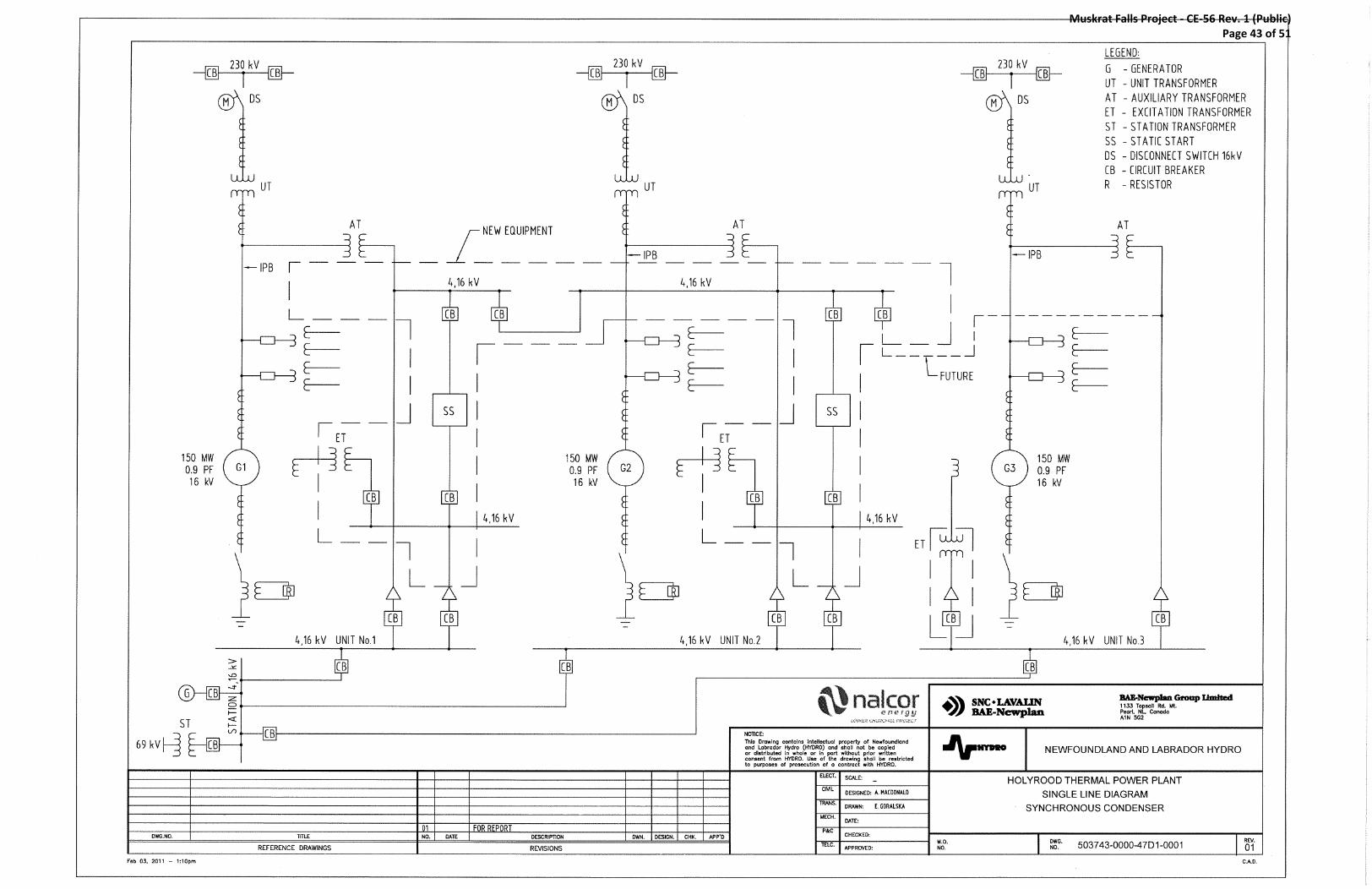
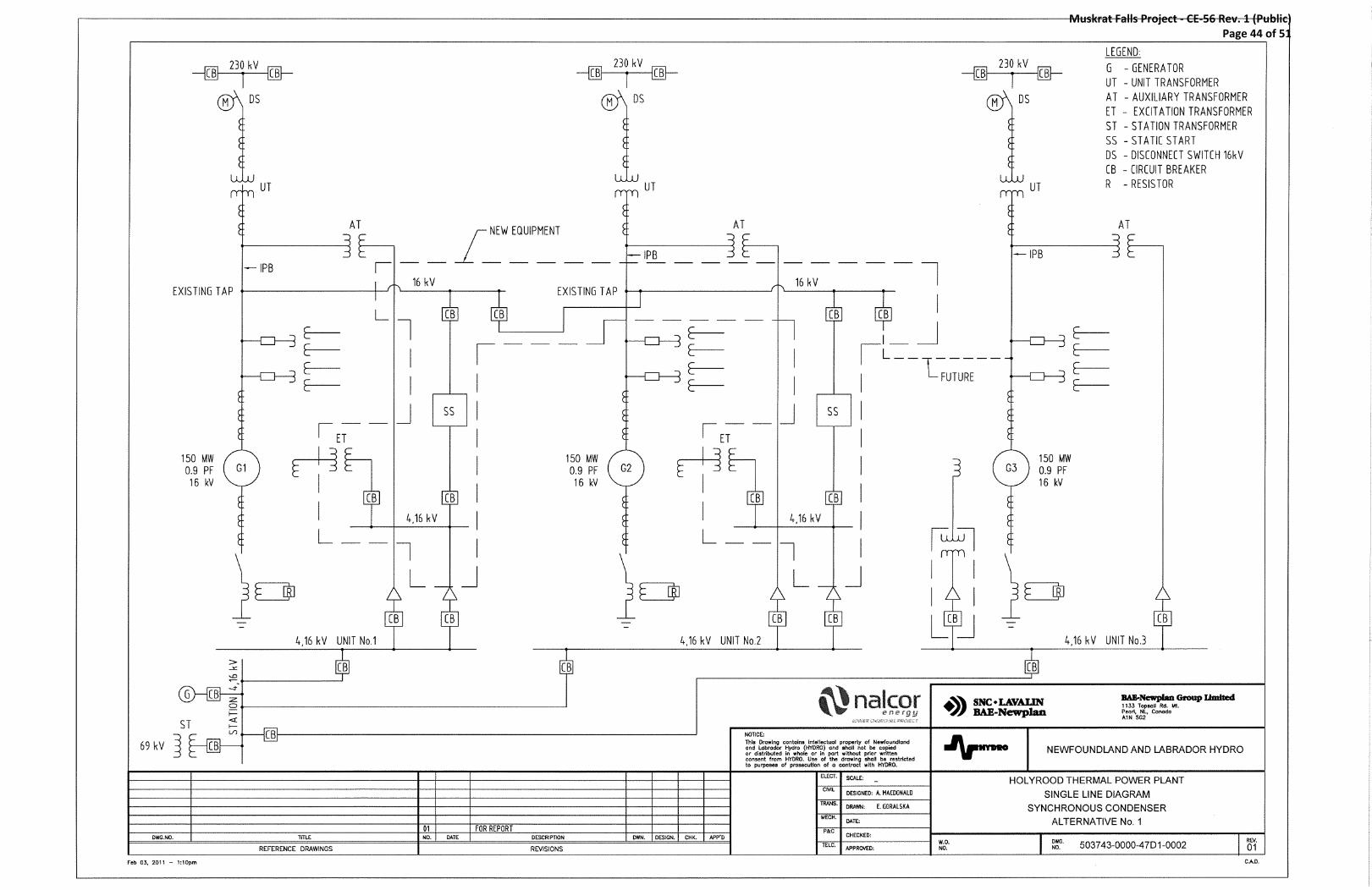
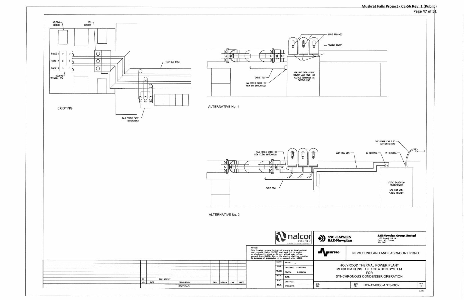
In SLD (Single Line Diagram) 0001 ( ) the SFC is connected to the isolated phase busduct through the secondary of the unit station service transformer using a remotely operated disconnect/contactor.
In SLD 0002, the SFC is fed directly to the terminals of the generator through a remotely operated disconnect switch or circuit breakers. The connection to the Synchronous Condenser will be at the isolated phase busduct tap used for the excitation transformer.
A new excitation transformer is necessary since excitation power from the MV (4.16 kV) station auxiliary service bus is required during start up. An alternative approach would be to procure a system that combines a static excitation system and a static frequency converter which could provide space and installation cost savings and simplify the control system integration.
The excitation transformers would have to be replaced with units fed from the medium voltage bus since excitation is required during start-up. If the bus duct taps are used to connect the SFCs to the generators, the new transformers will have to be located at the other end of the excitation line-up and a low voltage busduct will be used to connect the transformer to the rectifier. If the busduct taps are not used, the new transformer would be located in the same location as it is currently. The transformers would have side mounted bushings for power cables. The busduct taps would be sealed off. There are several stages to the starting run-up. Initially between standstill and a chosen speed the acceleration takes place at constant torque where the terminal voltage of the machine rises in proportion to the speed until the inverter’s rated voltage is reached. Acceleration continues with constant power while the excitation unit adjusts the machine voltage until the SFC unit is turned off a few percents above synchronous speed while operating at full line voltage. During the coasting down phase the generator breaker is closed after a successful synchronizing to the grid.
Information received from suppliers based on estimated data shows the proposed two configurations in Single Line Diagrams (SLDs) 503743-0000-47D1-0001 and 0002
The two types of Static Starter Units proposed are the Load commutated inverter (LCI) and the Voltage Source Inverter (VSI) units. The operation for both is similar in that the SC (Synchronous Condenser) would be accelerated from standstill or a few rpm to synchronous speed where the Static Start Unit would be disconnected and the SC synchronized to the grid using the high voltage circuit breaker.
The Static Starter Unit control system has to be integrated with the excitation system controls so as to adjust and monitor the machine’s voltage. The Static Starter Unit incorporates the generator protection required during starting.
The transformers and SFC cubicles will be located in the Mezzanine area as shown on drawing 503743-0000-47D3-0001.
Muskrat Falls Project - CE-56 Rev. 1 (Public) Page 15 of 51
Thermal Power 2-9 © 2011 SNC-Lavalin Inc.
All rights reserved - Confidential
Holyrood Synchronous Condenser Study 503743 - Rev. 02
2.5.2 Synchronous Condenser Starting Sequence
The starting procedure is a routine sequence that involves properly timed operations as well as the automatic checking of many mechanical and electrical conditions best done by the supervisory and control PLCs and DCS.
1) Prior to a unit start-up the different switching equipment will be in the following position:
a) Synchronous Condenser unit’s 230 kV breaker is open. b) Unit station service transformer circuit breaker is open. c) Unit station service is connected to the start-up supply from the 69kV
Switchyard. d) Static Frequency Start Unit (SFC) 4.16 kV supply circuit breaker is open. e) Static Exciter 4.16 kV supply circuit breaker is open. f) Shaft turning motor 600 V auxiliary supply starter is open. g) Lock-out relay has been reset. h) Supply voltages normal.
2) Energizing of the Auxiliaries: a) Start oil lift pumps and check of oil pressure. b) Hydrogen and oil coolers operational. c) Energize shaft turning motor and rotate shaft to approx. 5 rpm.
3) Synchronous Condenser (SC) Start-up: a) Stop shaft turning motor. b) Close the Exciter 4.16 kV breaker in the supply switchgear. c) Close the SFC Start Unit 4.16 kV breaker in the supply switchgear. d) Start of the Static Frequency Start Unit locally or from the DCS which will
initiate the field excitation and energize the stator winding by closing the respective motorized switches or circuit breakers. Rotation is initiated.
e) All critical operating conditions and values are checked continuously by the control system as to whether they remain within the permissible operating limits. Any abnormality will cause a lock-out.
f) In the initial acceleration phase the machine terminal voltage rises in proportion to the speed with a constant excitation.
g) The acceleration to slightly over synchronous speed is achieved by the SFC controls regulating the voltage/current and the exciter so as to achieve the required acceleration within the V/Hz limits.
h) The excitation adjusts the machine terminal voltage to the nominal voltage. i) Motorized switch or circuit breakers disconnects the SFC from the
Synchronous Condenser. j) SFC unit circuit breaker opened. k) In the coasting down phase, the machine/exciter controls are transitioned to
the plant’s controls (DCS). l) Upon a successful synchronization the unit’s 230 kV breaker is closed. m) Unit is loaded to required VARS.
Muskrat Falls Project - CE-56 Rev. 1 (Public) Page 16 of 51
Thermal Power 2-10 © 2011 SNC-Lavalin Inc.
All rights reserved - Confidential
Holyrood Synchronous Condenser Study 503743 - Rev. 02
Unit 4.16kV auxiliary board is transferred from station supply to unit transformer supply.
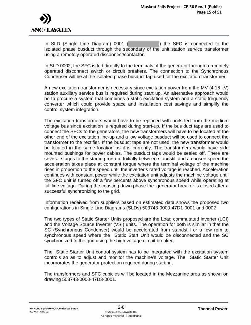
2.5.3 Typical SFC Hardware
Figure 8 Typical Static Start Unit with incoming disconnect/contactor and transformer
proposes an air cooled 24 pulse IGBT - VSI (Insulated Gate Bipolar Transistor – Voltage Source Inverter) which is packaged in a footprint comparable to the LCI (Load Conmutated Inverter) units proposed by the other suppliers. Their mean time between failures (MTBF) is specified as a minimum of 16 years with a mean time to repair (MTTR) of 15 min. The interfaces allow for communicating with ABBs Exciter open control system.
proposed LCI (load Comutated Inverters) units, Fig. 11 & 12, which are typically used in these applications due to their simplicity and lower cost. can readily integrate the Exciter and SFC controls with one HMI (Human Machine Interface) platform.
Muskrat Falls Project - CE-56 Rev. 1 (Public) Page 17 of 51
Thermal Power 2-11 © 2011 SNC-Lavalin Inc.
All rights reserved - Confidential
Holyrood Synchronous Condenser Study 503743 - Rev. 02
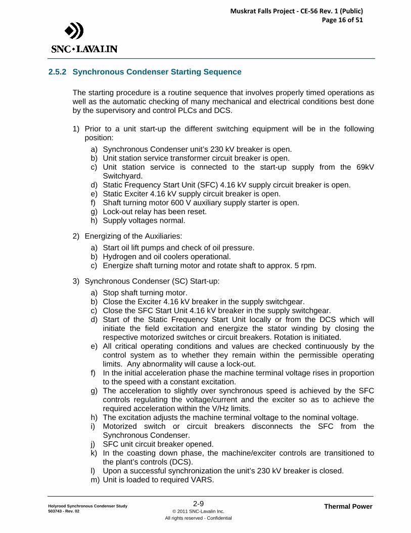
Figure 9 Typical Static Start Unit from
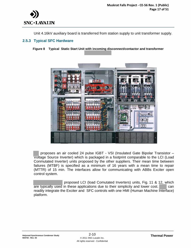
Figure 10 Typical Static Start Unit from (note this unit is containerized)
For the budgetary equipment list of this acceleration system arrangement, please see Appendix A.
Muskrat Falls Project - CE-56 Rev. 1 (Public) Page 18 of 51
Thermal Power 3-1 © 2011 SNC-Lavalin Inc.
All rights reserved - Confidential
Holyrood Synchronous Condenser Study 503743 - Rev. 02
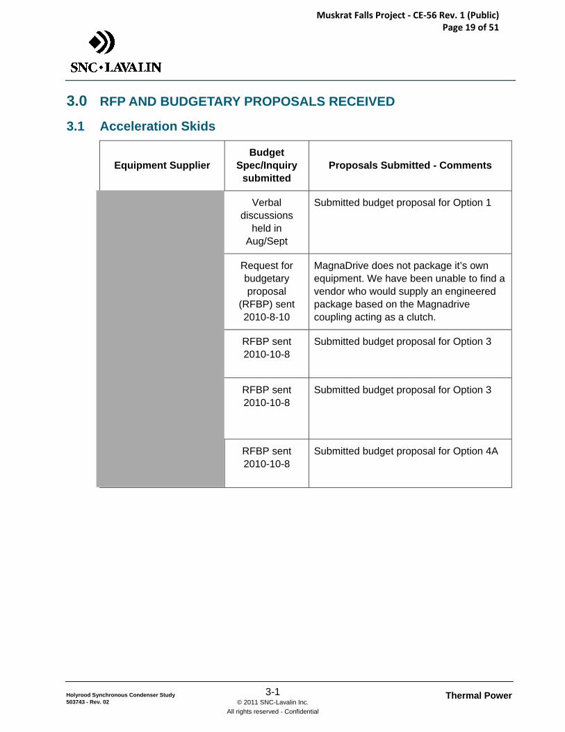
3.0 RFP AND BUDGETARY PROPOSALS RECEIVED
3.1 Acceleration Skids
Equipment Supplier Budget
Spec/Inquiry submitted
Proposals Submitted - Comments
Verbal discussions
held in Aug/Sept
Submitted budget proposal for Option 1
Request for budgetary proposal
(RFBP) sent 2010-8-10
MagnaDrive does not package it’s own equipment. We have been unable to find a vendor who would supply an engineered package based on the Magnadrive coupling acting as a clutch.
RFBP sent 2010-10-8
Submitted budget proposal for Option 3
RFBP sent 2010-10-8
Submitted budget proposal for Option 3
RFBP sent 2010-10-8
Submitted budget proposal for Option 4A
Muskrat Falls Project - CE-56 Rev. 1 (Public) Page 19 of 51
Thermal Power 3-2 © 2011 SNC-Lavalin Inc.
All rights reserved - Confidential
Holyrood Synchronous Condenser Study 503743 - Rev. 02
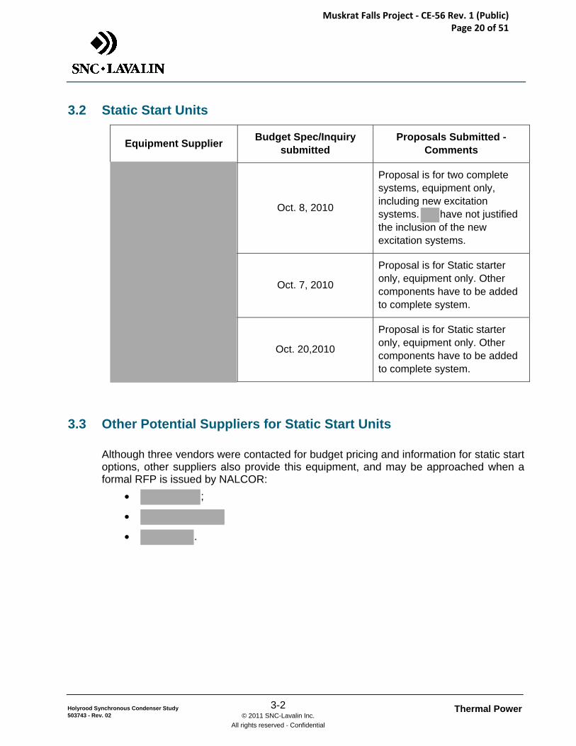
3.2 Static Start Units
Equipment Supplier Budget Spec/Inquiry submitted
Proposals Submitted - Comments
Oct. 8, 2010
Proposal is for two complete systems, equipment only, including new excitation systems. have not justified the inclusion of the new excitation systems.
Oct. 7, 2010
Proposal is for Static starter only, equipment only. Other components have to be added to complete system.
Oct. 20,2010
Proposal is for Static starter only, equipment only. Other components have to be added to complete system.
3.3 Other Potential Suppliers for Static Start Units
Although three vendors were contacted for budget pricing and information for static start options, other suppliers also provide this equipment, and may be approached when a formal RFP is issued by NALCOR:
• ;
•
• .
Muskrat Falls Project - CE-56 Rev. 1 (Public) Page 20 of 51
Thermal Power 4-1 © 2011 SNC-Lavalin Inc.
All rights reserved - Confidential
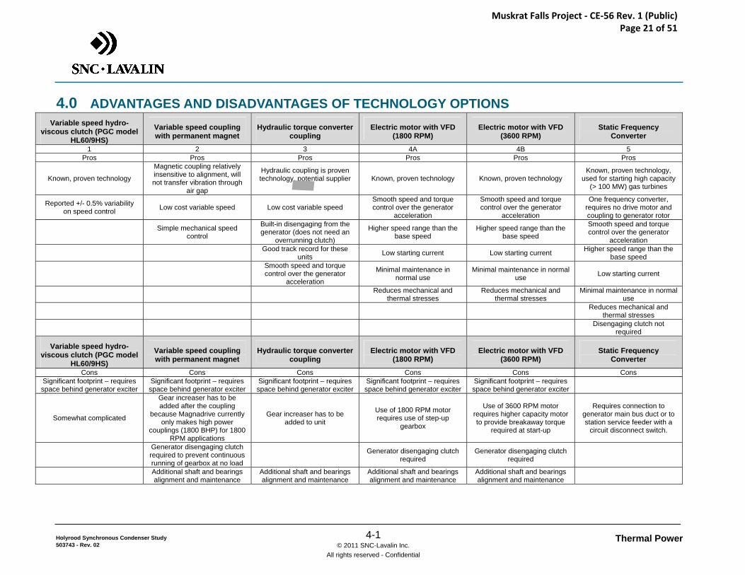
Holyrood Synchronous Condenser Study 503743 - Rev. 02
4.0 ADVANTAGES AND DISADVANTAGES OF TECHNOLOGY OPTIONS Variable speed hydro-
viscous clutch (PGC model HL60/9HS)
Variable speed coupling with permanent magnet
Hydraulic torque converter coupling
Electric motor with VFD (1800 RPM)
Electric motor with VFD (3600 RPM)
Static Frequency Converter
1 2 3 4A 4B 5 Pros Pros Pros Pros Pros Pros
Known, proven technology
Magnetic coupling relatively insensitive to alignment, will not transfer vibration through
air gap
Hydraulic coupling is proven technology, potential supplier
Known, proven technology Known, proven technology
Known, proven technology, used for starting high capacity
(> 100 MW) gas turbines
Reported +/- 0.5% variability on speed control Low cost variable speed Low cost variable speed
Smooth speed and torque control over the generator
acceleration
Smooth speed and torque control over the generator
acceleration
One frequency converter, requires no drive motor and coupling to generator rotor
Simple mechanical speed control
Built-in disengaging from the generator (does not need an
overrunning clutch)
Higher speed range than the base speed
Higher speed range than the base speed
Smooth speed and torque control over the generator
acceleration
Good track record for these units Low starting current Low starting current Higher speed range than the
base speed
Smooth speed and torque control over the generator
acceleration
Minimal maintenance in normal use
Minimal maintenance in normal use Low starting current
Reduces mechanical and thermal stresses
Reduces mechanical and thermal stresses
Minimal maintenance in normal use
Reduces mechanical and thermal stresses
Disengaging clutch not required
Variable speed hydro-viscous clutch (PGC model
HL60/9HS)
Variable speed coupling with permanent magnet
Hydraulic torque converter coupling
Electric motor with VFD (1800 RPM)
Electric motor with VFD (3600 RPM)
Static Frequency Converter
Cons Cons Cons Cons Cons Cons Significant footprint – requires space behind generator exciter
Significant footprint – requires space behind generator exciter
Significant footprint – requires space behind generator exciter
Significant footprint – requires space behind generator exciter
Significant footprint – requires space behind generator exciter
Somewhat complicated
Gear increaser has to be added after the coupling
because Magnadrive currently only makes high power
couplings (1800 BHP) for 1800 RPM applications
Gear increaser has to be added to unit
Use of 1800 RPM motor requires use of step-up
gearbox
Use of 3600 RPM motor requires higher capacity motor to provide breakaway torque
required at start-up
Requires connection to generator main bus duct or to station service feeder with a
circuit disconnect switch.
Generator disengaging clutch required to prevent continuous running of gearbox at no load
Generator disengaging clutch required
Generator disengaging clutch required
Additional shaft and bearings alignment and maintenance
Additional shaft and bearings alignment and maintenance
Additional shaft and bearings alignment and maintenance
Additional shaft and bearings alignment and maintenance
Muskrat Falls Project - CE-56 Rev. 1 (Public) Page 21 of 51
Thermal Power 5-1 © 2011 SNC-Lavalin Inc.
All rights reserved - Confidential
Holyrood Synchronous Condenser Study 503743 - Rev. 02
5.0 MODIFICATIONS REQUIRED TO UNITS 1 & 2 GENERATOR ROTORS.
In order to convert the existing unit 1 and 2 generators to synchronous condensers and operate independently of the steam turbines, several circumstances and modifications need to be considered.
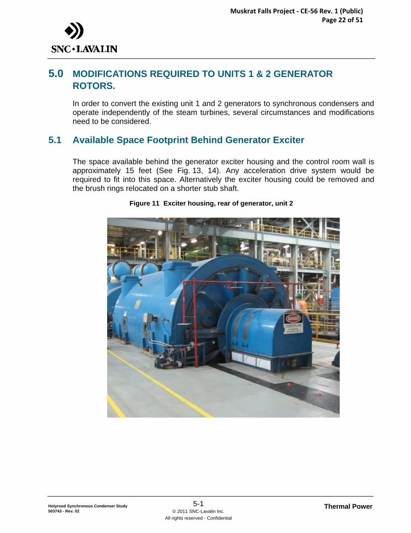
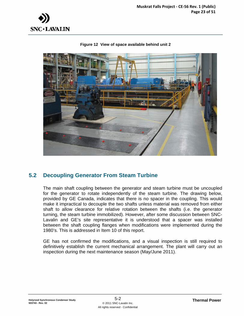
5.1 Available Space Footprint Behind Generator Exciter
The space available behind the generator exciter housing and the control room wall is approximately 15 feet (See Fig. 13, 14). Any acceleration drive system would be required to fit into this space. Alternatively the exciter housing could be removed and the brush rings relocated on a shorter stub shaft.
Figure 11 Exciter housing, rear of generator, unit 2
Muskrat Falls Project - CE-56 Rev. 1 (Public) Page 22 of 51
Thermal Power 5-2 © 2011 SNC-Lavalin Inc.
All rights reserved - Confidential
Holyrood Synchronous Condenser Study 503743 - Rev. 02
Figure 12 View of space available behind unit 2
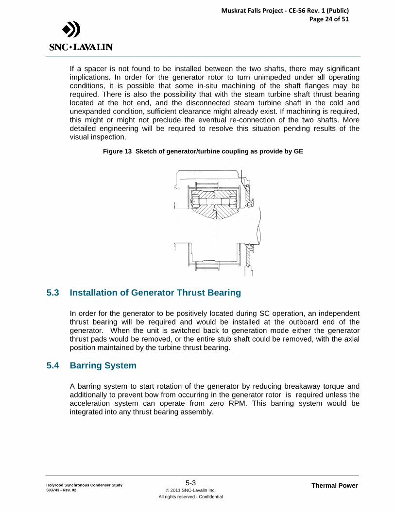
5.2 Decoupling Generator From Steam Turbine
The main shaft coupling between the generator and steam turbine must be uncoupled for the generator to rotate independently of the steam turbine. The drawing below, provided by GE Canada, indicates that there is no spacer in the coupling. This would make it impractical to decouple the two shafts unless material was removed from either shaft to allow clearance for relative rotation between the shafts (i.e. the generator turning, the steam turbine immobilized). However, after some discussion between SNC-Lavalin and GE’s site representative it is understood that a spacer was installed between the shaft coupling flanges when modifications were implemented during the 1980’s. This is addressed in Item 10 of this report.
GE has not confirmed the modifications, and a visual inspection is still required to definitively establish the current mechanical arrangement. The plant will carry out an inspection during the next maintenance season (May/June 2011).
Muskrat Falls Project - CE-56 Rev. 1 (Public) Page 23 of 51
Thermal Power 5-3 © 2011 SNC-Lavalin Inc.
All rights reserved - Confidential
Holyrood Synchronous Condenser Study 503743 - Rev. 02
If a spacer is not found to be installed between the two shafts, there may significant implications. In order for the generator rotor to turn unimpeded under all operating conditions, it is possible that some in-situ machining of the shaft flanges may be required. There is also the possibility that with the steam turbine shaft thrust bearing located at the hot end, and the disconnected steam turbine shaft in the cold and unexpanded condition, sufficient clearance might already exist. If machining is required, this might or might not preclude the eventual re-connection of the two shafts. More detailed engineering will be required to resolve this situation pending results of the visual inspection.
Figure 13 Sketch of generator/turbine coupling as provide by GE
5.3 Installation of Generator Thrust Bearing
In order for the generator to be positively located during SC operation, an independent thrust bearing will be required and would be installed at the outboard end of the generator. When the unit is switched back to generation mode either the generator thrust pads would be removed, or the entire stub shaft could be removed, with the axial position maintained by the turbine thrust bearing.
5.4 Barring System
A barring system to start rotation of the generator by reducing breakaway torque and additionally to prevent bow from occurring in the generator rotor is required unless the acceleration system can operate from zero RPM. This barring system would be integrated into any thrust bearing assembly.
Muskrat Falls Project - CE-56 Rev. 1 (Public) Page 24 of 51
Thermal Power 5-4 © 2011 SNC-Lavalin Inc.
All rights reserved - Confidential
Holyrood Synchronous Condenser Study 503743 - Rev. 02
5.5 Conversion Process
The conversion from generator to synchronous condenser operation requires the previously outlined modifications followed by an automatically controlled starting and synchronizing sequence that ensures that all preconditions are met.
As presented in the previous sections, synchronous condenser rotor acceleration torque can be obtained by an induction motor connected to the condenser shaft or by self-starting using a static frequency converter (SFC) source.
The issues encountered when a synchronous condenser is brought up to speed with an induction motor and then put on line, are exactly the same as when a generator is synchronized and put on line i.e.: the machine must be brought to synchronous speed, the voltage matched and synchronized to the line voltage followed by closing the running breaker. The transients are minimized when closing the breaker by matching closely the voltage and phase.
A static frequency converter (SFC) system accelerates synchronous machines using the interaction of the stator and the rotor fields, where the rotor field must be energized and set from the SFC from standstill to running speed so as to generate the necessary acceleration torque. Note that the exciter and machine controls must be designed to transition from being controlled by the SFC drive to being controlled by the utility operation controls after synchronization.
Functions such as breaker/contactor interlocking, field reference control, synchronizing supervisory logic, operator control / HMI (Human Machine Interface) and overall DCS or plant interface must be integrated in the System Logic and Drive Control. These functions will be divided between the drive’s PLC and the synchronous condenser/generator DCS controls.
5.6 Auxiliary Systems
Modification of the turbine lube oil distribution piping is expected to be required. Based on the changes made on unit 3, some additional valving will be required to isolate the turbine bearings during synchronous condenser operation, and flow orifices will be needed to limit the flow to the generator.
Cooling water for unit 3 generator is supplied by an auxiliary pump during synchronous condenser operation. It is not expected that this pump will have sufficient capacity for an additional unit, however some additional capacity could be realized by increasing its operating speed. An additional pump is expected to be required and together the two pumps could serve all three units.
No modifications are foreseen to the generator hydrogen gas system.
Muskrat Falls Project - CE-56 Rev. 1 (Public) Page 25 of 51
Thermal Power 6-1 © 2011 SNC-Lavalin Inc.
All rights reserved - Confidential
Holyrood Synchronous Condenser Study 503743 - Rev. 02
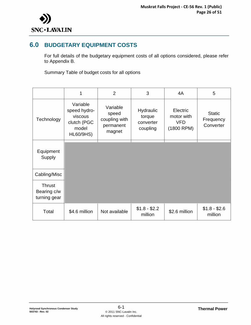
6.0 BUDGETARY EQUIPMENT COSTS
For full details of the budgetary equipment costs of all options considered, please refer to Appendix B.
Summary Table of budget costs for all options
1 2 3 4A 5
Technology
Variable speed hydro-
viscous clutch (PGC
model HL60/9HS)
Variable speed
coupling with permanent
magnet
Hydraulic torque
converter coupling
Electric motor with
VFD (1800 RPM)
Static Frequency Converter
Equipment Supply
Cabling/Misc
Thrust Bearing c/w turning gear
Total $4.6 million Not available $1.8 - $2.2 million $2.6 million $1.8 - $2.6
million
Muskrat Falls Project - CE-56 Rev. 1 (Public) Page 26 of 51
Thermal Power 7-1 © 2011 SNC-Lavalin Inc.
All rights reserved - Confidential
Holyrood Synchronous Condenser Study 503743 - Rev. 02
7.0 RECOMMENDATION FOR TECHNOLOGY
7.1 Recommendation
SNC-Lavalin recommends the Static Frequency Converter technology for this application for the following reasons:
• Ease of conversion:
Due to the self starting feature no other equipment is required to be installed at the generator/synchronous condenser floor space. The mechanical modifications are limited to the turbine coupling spacer and bearing pads, please refer to section 5.
• High reliability:
The inherent availability of Static Frequency Converters or Variable Speed Drives is excellent due to mature/reliable components and modular construction e.g.: IEEE standard #493 Appendix Q, provides an inherent availability 0.999958 for Variable Speed Drives; (inherent availability being MTBF/(MTBF+MTTR) where MTBF is the Mean Time Between Failures and MTTR is the Mean Time To Repair.
publishes for their proposed unit a MTBF of 16 years and a MTTR of 15 minutes i.e.: an inherent availability of 0.999998. Note that inherent availability considers down time for repair of failures only, no logistics time allowance.
• Soft start capability:
The acceleration amperage drawn initially from the auxiliary supply is low (magnetization) and increases with speed where the stator voltage and current are regulated to provide the torque required for the chosen acceleration.
• One unit can be used for multiple machines.
One SFC can be used to start one or more units by switching the output to the unit being started using additional output switches/contactors. However, for reliability reasons redundancy is recommended.
• New equipment can be installed remotely
Unlike the acceleration skids, the majority of the equipment is not located on the generator floor.
Muskrat Falls Project - CE-56 Rev. 1 (Public) Page 27 of 51
Thermal Power 7-2 © 2011 SNC-Lavalin Inc.
All rights reserved - Confidential
Holyrood Synchronous Condenser Study 503743 - Rev. 02
The selection of the Static Frequency Converter supplier must be based on the following in order of priority:
• Experience integrating similar installations;
• Long term record of support for their supply;
• Price.
A condition assessment including specialized testing of the generator and associated equipment condition as discussed during the presentation meeting must be done to verify the condition of the generator windings and insulation prior to implementing the SC modifications. Extent of repair and/or rewind would be determined by the results of the condition assessment.
7.2 Single Line Diagram (SLD)
Two single line diagrams have been prepared to illustrate the proposed electrical design and arrangement (drawing no. 503743-0000-47D1-0001 Rev 01). An alternative arrangement has also been considered in SLD drawing no. 503743-0000-47D1-0002 Rev 01. Both SLD’s are presented in Appendix D of this report.
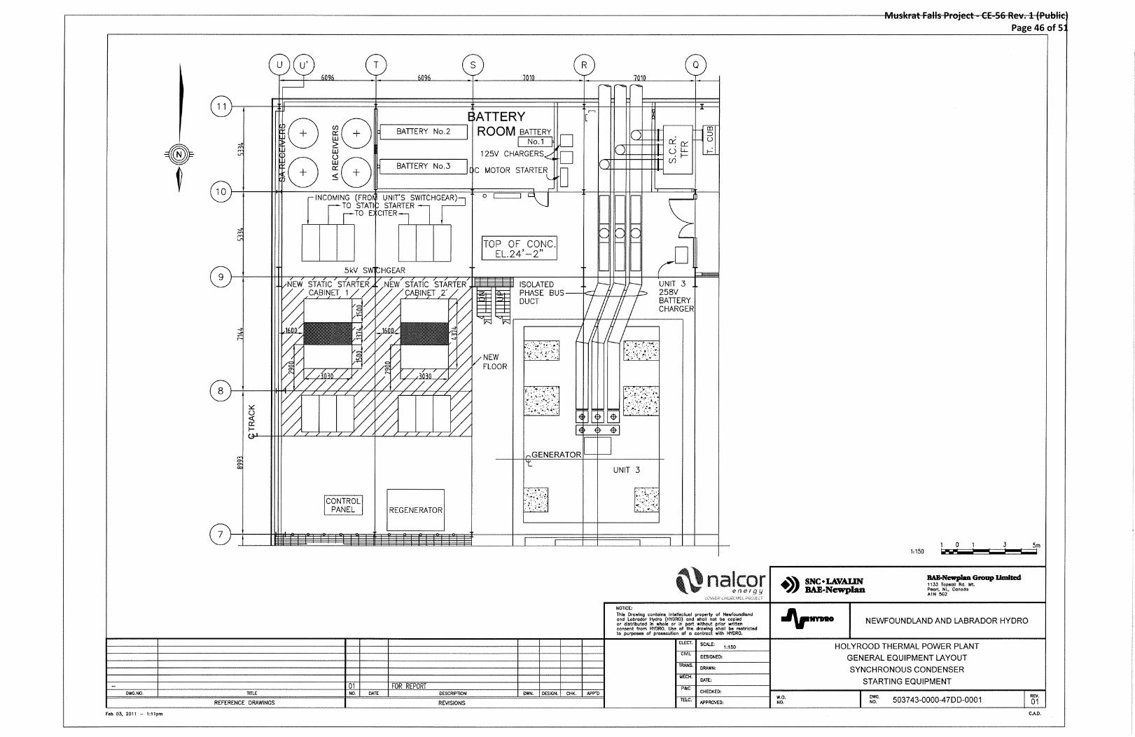
7.3 Proposed Equipment Location
The proposed location for the static starter units is on floor level 24’-2”, North of the battery room, East of the unit 3 generator bus ducts. They will be situated between columns U-S and columns 8-9. Please see Drawing 503743-0000-47D3-0001 Rev 01 in Appendix E. The existing floor would be extended for this purpose.
Note that the new excitation transformers will be located in the same area as the existing units. See drawing 503743-0000-47D3-0002 Rev 00 in Appendix E
Muskrat Falls Project - CE-56 Rev. 1 (Public) Page 28 of 51
Thermal Power 8-1 © 2011 SNC-Lavalin Inc.
All rights reserved - Confidential
Holyrood Synchronous Condenser Study 503743 - Rev. 02
8.0 COST ESTIMATE FOR RECOMMENDED OPTION
8.1 Direct Costs
The capital cost estimate has been prepared based on budgetary price information provided by The price for the generator thrust bearing, turning gear and stub shaft assembly was provided by .
Unit pricing for standard equipment and bulk material was taken from SNCL’s in-house database. Installation costs include labor and direct supervision with labour rates for 2010 in Newfoundland.
The capital cost estimates includes the following equipment and services:
• 2 static starter systems (prices based on most competitive received);
• 2 excitation transformers;
• 2 static starter output switchgears, each with 2 circuit breakers;
• 2 static starter input switchgears, each with 2 circuit breakers;
• 2 generator thrust bearing, stub shaft and turning gear assemblies;
• Allowance for modifications to units 1 & 2 turbine lube oil distribution piping;
• Allowance for an additional CW supply pump and capacity increase of existing pump;
• Integration of the static starting system with the existing STG controls, excitation and protection;
• Cabling, trays, and terminations;
• Installation by qualified contractor.
8.2 Indirect Costs
Indirect costs have been estimated based on typical percentages of the project Direct Costs
Engineering includes detail engineering services and engineering support during installation. It was assumed that NALCOR would be maintain responsibility for construction site management and cost control given that Holyrood would remain in operation during the conversion.
A separate amount has been allocated for integration of the new equipment with the existing ABB excitation. This amount covers both commissioning of the new equipment and any necessary interfacing between the two systems.
Muskrat Falls Project - CE-56 Rev. 1 (Public) Page 29 of 51
Thermal Power 8-2 © 2011 SNC-Lavalin Inc.
All rights reserved - Confidential
Holyrood Synchronous Condenser Study 503743 - Rev. 02
The Contractors’ indirect costs include mobilization and demobilization, construction facilities, fees, liability insurance, warehouse, stores, first aid, etc
A contingency is included to cover items which cannot be defined given the engineering completed to date. The contingency amount is expected to be needed as the project is more closely defined and detail items are identified. It is not intended to cover over-budget costs.
The cost estimate is given in 2010 Canadian Dollars, with an allowance of 2% per year for inflation to 2014 implementation.
8.3 Exclusions
The following items are not included in the estimate:
• Owner’s project development and management, legal fees, environmental studies, permitting fees etc.;
• Owner’s salary costs during project implementation;
• Financing fees;
• Interest during construction;
• Initial Plant Costs including O&M preparation, staff training, initial spare parts;
• Working Capital;
• Cabling for unit 3 and modifications to the excitation system;
• Modifications to existing CW distribution piping and intake;
• Partition walls to facilitate selective heating once conversion to SC operation is complete.
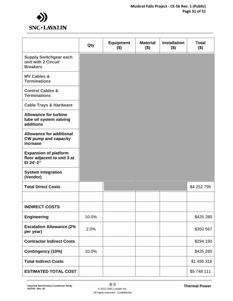
Description Qty Equipment ($)
Material ($)
Installation ($)
Total ($)
DIRECT COSTS
Thrust Bearing incl. Stub Shaft & Turning Gear
Static Starter Output Switchgear each unit with 2 circuit breakers
Static Starters
Excitation Transformers
Muskrat Falls Project - CE-56 Rev. 1 (Public) Page 30 of 51
Thermal Power 8-3 © 2011 SNC-Lavalin Inc.
All rights reserved - Confidential
Holyrood Synchronous Condenser Study 503743 - Rev. 02
Description Qty Equipment ($)
Material ($)
Installation ($)
Total ($)
Supply Switchgear each unit with 2 Circuit Breakers
MV Cables & Terminations
Control Cables & Terminations
Cable Trays & Hardware
Allowance for turbine lube oil system valving additions
Allowance for additional CW pump and capacity increase
Expansion of platform floor adjacent to unit 3 at EI 24’-2”
System Integration (Vendor)
Total Direct Costs $4 252 795
INDIRECT COSTS
Engineering 10.0% $425 280
Escalation Allowance (2% per year) 2.0% $350 567
Contractor Indirect Costs $294 190
Contingency (10%) 10.0% $425 280
Total Indirect Costs $1 495 316
ESTIMATED TOTAL COST $5 748 111
Muskrat Falls Project - CE-56 Rev. 1 (Public) Page 31 of 51

Thermal Power 8-4 © 2011 SNC-Lavalin Inc.
All rights reserved - Confidential
Holyrood Synchronous Condenser Study 503743 - Rev. 02
8.4 Alternative Configuration
has provided a budgetary estimate for a full scope Synchronous Condenser conversion which includes a separate SFC system for each machine, new
control, new excitation systems and auxiliaries, and the generator thrust bearing and integrated turning gear. NALCOR may wish to consider this alternative, however it is based on a considerably enlarged scope of work than the cost estimate presented above. budget price for two units is plus cabling, cable trays, and all indirect costs.
8.5 Estimate Accuracy
The cost estimate is based on vendor budget prices for all equipment and SLI database information for bulk material and labour costs. As such the estimate meets the criteria for AACE class 4 and carries an expected accuracy of ±25%.
Muskrat Falls Project - CE-56 Rev. 1 (Public) Page 32 of 51
Thermal Power 9-1 © 2011 SNC-Lavalin Inc.
All rights reserved - Confidential
Holyrood Synchronous Condenser Study 503743 - Rev. 02
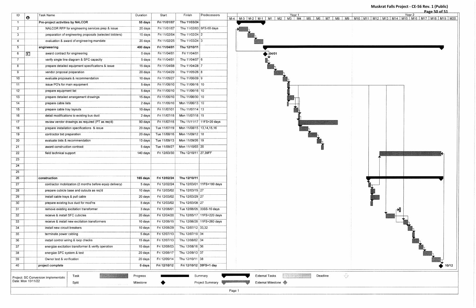
9.0 PRELIMINARY PROJECT SCHEDULE
A preliminary project schedule has been prepared to outline the various steps required to engineer, procure and install the proposed static starter system for Holyrood, and the estimated timeline to do so.
The overall project length from internal initiation at NALCOR is estimated to be approximately 22 months, with the first three months used internally at NALCOR for the preparation of the RFP for Engineering services and selection of the Engineer.
Upon initiation of the project with the Engineer, the Engineering is anticipated to take approximately six months, with a further seven months of Engineering support during the construction and installation period.
The purchase orders for the main equipment would be issued between 2 and 3 months from initiation of Engineering, and the delivery lead time is anticipated to be between eight and twelve months depending on the supplier.
The contractor would be mobilized at month twelve from initiation of Engineering, about two months before receipt at site of the main equipment, and the construction and installation period will be approximately seven months.
Please refer to the project implementation schedule in Appendix G for more details.
Muskrat Falls Project - CE-56 Rev. 1 (Public) Page 33 of 51
Thermal Power 10-1 © 2011 SNC-Lavalin Inc.
All rights reserved - Confidential
Holyrood Synchronous Condenser Study 503743 - Rev. 02
10.0 ITEMS TO BE INCLUDED IN NEXT PHASE
Should NALCOR decide to proceed with the implementation of a static frequency converter system for Holyrood, the following issues will need to be addressed as the next step in the implementation sequence:
1) As discussed in section 5.2 of this report, the details of the coupling between the generator shaft and steam turbine shaft as it exists today must be firmly established.
2) The technical compatibility of the new SFC with existing systems, in particular the existing ABB exciters must be confirmed. Any RFPs to suppliers would specify compatibility as a requirement, but only upon receipt of actual bids can this be fully reviewed.
3) The generator rotor inertia information should be reviewed in detail (some initial information is provided in the report in Appendix C) and an Engineering review of the capacity of the SFC required for an acceptable acceleration rate of the generator shall be carried out.
4) Thorough review of all systems, sub-systems, and auxiliaries.
Muskrat Falls Project - CE-56 Rev. 1 (Public) Page 34 of 51
Thermal Power Appendix A © 2011 SNC-Lavalin Inc.
All rights reserved - Confidential
Holyrood Synchronous Condenser Study 503743 - Rev. 02
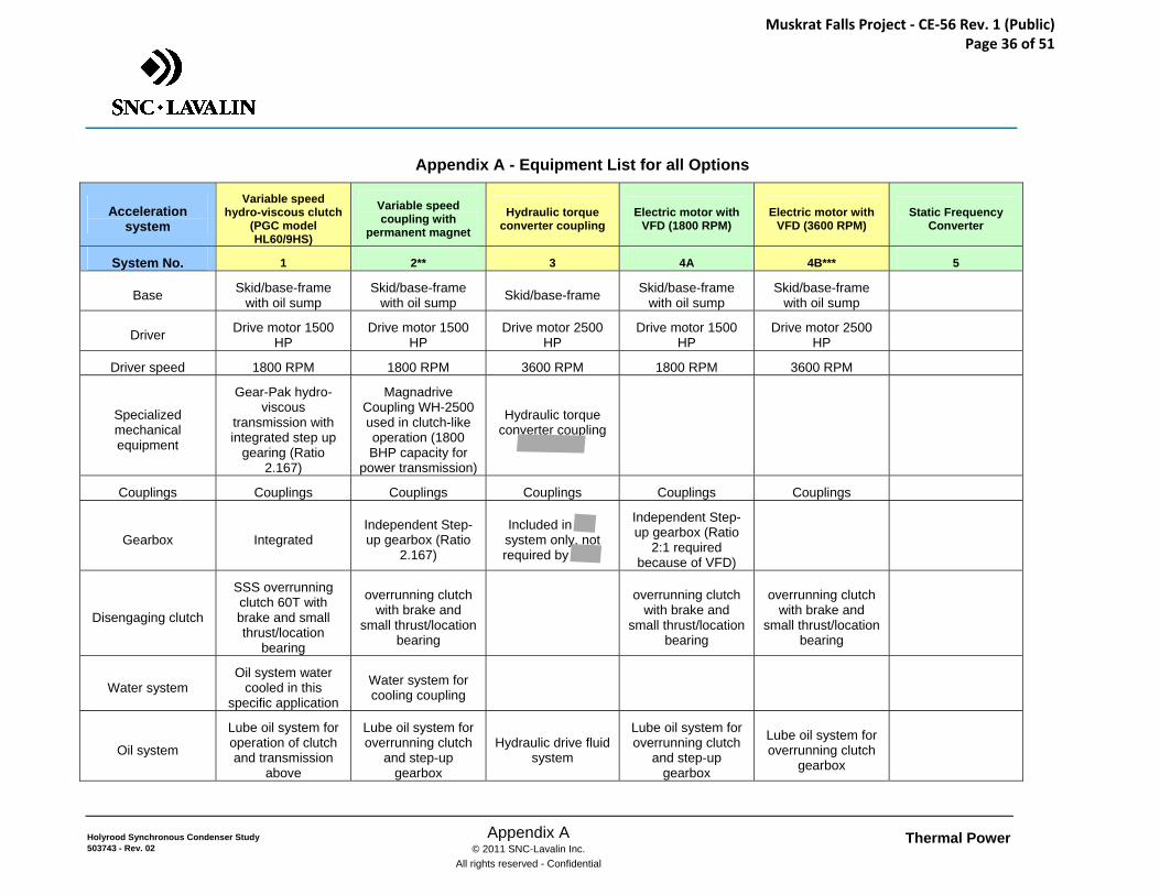
APPENDIX A
Equipment List for all Options
Muskrat Falls Project - CE-56 Rev. 1 (Public) Page 35 of 51
Thermal Power Appendix A © 2011 SNC-Lavalin Inc.
All rights reserved - Confidential
Holyrood Synchronous Condenser Study 503743 - Rev. 02
Appendix A - Equipment List for all Options
Acceleration system
Variable speed hydro-viscous clutch
(PGC model HL60/9HS)
Variable speed coupling with
permanent magnet Hydraulic torque
converter coupling Electric motor with
VFD (1800 RPM) Electric motor with
VFD (3600 RPM) Static Frequency
Converter
System No. 1 2** 3 4A 4B*** 5
Base Skid/base-frame with oil sump
Skid/base-frame with oil sump Skid/base-frame Skid/base-frame
with oil sump Skid/base-frame
with oil sump
Driver Drive motor 1500 HP
Drive motor 1500 HP
Drive motor 2500 HP
Drive motor 1500 HP
Drive motor 2500 HP
Driver speed 1800 RPM 1800 RPM 3600 RPM 1800 RPM 3600 RPM
Specialized mechanical equipment
Gear-Pak hydro-viscous
transmission with integrated step up
gearing (Ratio 2.167)
Magnadrive Coupling WH-2500 used in clutch-like operation (1800 BHP capacity for
power transmission)
Hydraulic torque converter coupling
Couplings Couplings Couplings Couplings Couplings Couplings
Gearbox Integrated Independent Step-up gearbox (Ratio
2.167)
Included in system only, not required by
Independent Step-up gearbox (Ratio
2:1 required because of VFD)
Disengaging clutch
SSS overrunning clutch 60T with brake and small thrust/location
bearing
overrunning clutch with brake and
small thrust/location bearing
overrunning clutch with brake and
small thrust/location bearing
overrunning clutch with brake and
small thrust/location bearing
Water system Oil system water
cooled in this specific application
Water system for cooling coupling
Oil system
Lube oil system for operation of clutch and transmission
above
Lube oil system for overrunning clutch
and step-up gearbox
Hydraulic drive fluid system
Lube oil system for overrunning clutch
and step-up gearbox
Lube oil system for overrunning clutch
gearbox
Muskrat Falls Project - CE-56 Rev. 1 (Public) Page 36 of 51
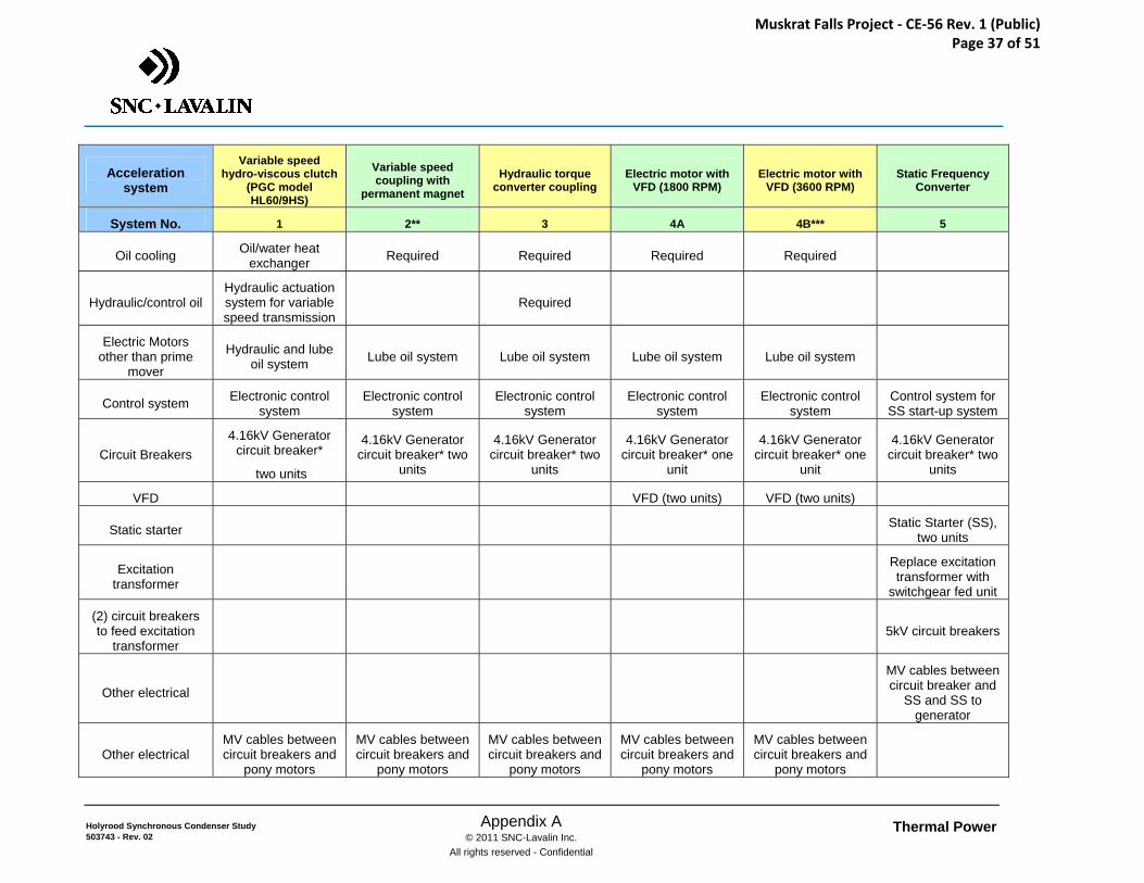
Thermal Power Appendix A © 2011 SNC-Lavalin Inc.
All rights reserved - Confidential
Holyrood Synchronous Condenser Study 503743 - Rev. 02
Acceleration system
Variable speed hydro-viscous clutch
(PGC model HL60/9HS)
Variable speed coupling with
permanent magnet
Hydraulic torque converter coupling
Electric motor with VFD (1800 RPM)
Electric motor with VFD (3600 RPM)
Static Frequency Converter
System No. 1 2** 3 4A 4B*** 5
Oil cooling Oil/water heat exchanger Required Required Required Required
Hydraulic/control oil Hydraulic actuation system for variable speed transmission
Required
Electric Motors other than prime
mover
Hydraulic and lube oil system Lube oil system Lube oil system Lube oil system Lube oil system
Control system Electronic control system
Electronic control system
Electronic control system
Electronic control system
Electronic control system
Control system for SS start-up system
Circuit Breakers 4.16kV Generator
circuit breaker*
two units
4.16kV Generator circuit breaker* two
units
4.16kV Generator circuit breaker* two
units
4.16kV Generator circuit breaker* one
unit
4.16kV Generator circuit breaker* one
unit
4.16kV Generator circuit breaker* two
units
VFD VFD (two units) VFD (two units)
Static starter Static Starter (SS), two units
Excitation transformer
Replace excitation transformer with
switchgear fed unit
(2) circuit breakers to feed excitation
transformer 5kV circuit breakers
Other electrical
MV cables between circuit breaker and
SS and SS to generator
Other electrical MV cables between circuit breakers and
pony motors
MV cables between circuit breakers and
pony motors
MV cables between circuit breakers and
pony motors
MV cables between circuit breakers and
pony motors
MV cables between circuit breakers and
pony motors
Muskrat Falls Project - CE-56 Rev. 1 (Public) Page 37 of 51
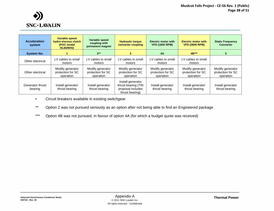
Thermal Power Appendix A © 2011 SNC-Lavalin Inc.
All rights reserved - Confidential
Holyrood Synchronous Condenser Study 503743 - Rev. 02
Acceleration system
Variable speed hydro-viscous clutch
(PGC model HL60/9HS)
Variable speed coupling with
permanent magnet
Hydraulic torque converter coupling
Electric motor with VFD (1800 RPM)
Electric motor with VFD (3600 RPM)
Static Frequency Converter
System No. 1 2** 3 4A 4B*** 5
Other electrical LV cables to small motors
LV cables to small motors
LV cables to small motors
LV cables to small motors
LV cables to small motors
Other electrical Modify generator protection for SC
operation
Modify generator protection for SC
operation
Modify generator protection for SC
operation
Modify generator protection for SC
operation
Modify generator protection for SC
operation
Modify generator protection for SC
operation
Generator thrust bearing
Install generator thrust bearing
Install generator thrust bearing
Install generator thrust bearing (TRI proposal includes
thrust bearing)
Install generator thrust bearing
Install generator thrust bearing
Install generator thrust bearing
∗ Circuit breakers available in existing switchgear
** Option 2 was not pursued seriously as an option after not being able to find an Engineered package
*** Option 4B was not pursued, in favour of option 4A (for which a budget quote was received)
Muskrat Falls Project - CE-56 Rev. 1 (Public) Page 38 of 51
Thermal Power Appendix B © 2011 SNC-Lavalin Inc.
All rights reserved - Confidential
Holyrood Synchronous Condenser Study 503743 - Rev. 02
APPENDIX B
Budget Costing for all Options
Muskrat Falls Project - CE-56 Rev. 1 (Public) Page 39 of 51
Thermal Power Appendix C © 2011 SNC-Lavalin Inc.
All rights reserved - Confidential
Holyrood Synchronous Condenser Study 503743 - Rev. 02
APPENDIX C
Rotor Inertia
Muskrat Falls Project - CE-56 Rev. 1 (Public) Page 40 of 51
Thermal Power Appendix C © 2011 SNC-Lavalin Inc.
All rights reserved - Confidential
Holyrood Synchronous Condenser Study 503743 - Rev. 02
Appendix C – Rotor Inertia
The inertia of the rotor of each generator has now been established. This information was not included in the GE generator data and drawings, but has been determined based on NALCOR's systems modeling (which itself was based on the CGE Contract Data obtained in April 1968). This data used in the stability model was received from NALCOR at the meeting in St. John’s of Oct 27, 2010.
H = 229.9 (MW) / 194.445 (Rated MVA) = 1.182
H = (0.231 * WK**2 * RPM) / ( KVA * 10E6) therefore
WK**2 = 76,790.50 (lb ft**2)
The GE rotor weight is given on the drawings/manuals as 66,500 lbs
For a solid cylinder WK**2 = 1/2 WR**2 which results in an approximate R = 1.55 or a Diameter = 3.10 ft (or approx. 37 inches).
Although the GE Generator Assembly Drawing 593E724AJ implies that the rotor would be less than 3 ft, NALCOR has confirmed that the diameter is in fact 37.25 inches.
Therefore, the rotor inertia for each generator is WK**2 = 76,790.50 (lb ft**2).
Muskrat Falls Project - CE-56 Rev. 1 (Public) Page 41 of 51
Thermal Power Appendix D © 2011 SNC-Lavalin Inc.
All rights reserved - Confidential
Holyrood Synchronous Condenser Study 503743 - Rev. 02
APPENDIX D
Single Line Diagrams (SLD)
Muskrat Falls Project - CE-56 Rev. 1 (Public) Page 42 of 51
Muskrat Falls Project - CE-56 Rev. 1 (Public) Page 43 of 51
Muskrat Falls Project - CE-56 Rev. 1 (Public) Page 44 of 51
Thermal Power Appendix E © 2011 SNC-Lavalin Inc.
All rights reserved - Confidential
Holyrood Synchronous Condenser Study 503743 - Rev. 02
APPENDIX E
General Layout and Alternatives Layouts for Excitation System
Muskrat Falls Project - CE-56 Rev. 1 (Public) Page 45 of 51
Muskrat Falls Project - CE-56 Rev. 1 (Public) Page 46 of 51
Muskrat Falls Project - CE-56 Rev. 1 (Public) Page 47 of 51
Thermal Power Appendix F © 2011 SNC-Lavalin Inc.
All rights reserved - Confidential
Holyrood Synchronous Condenser Study 503743 - Rev. 02
APPENDIX F
Quotes from Static Start Unit Suppliers
Muskrat Falls Project - CE-56 Rev. 1 (Public) Page 48 of 51
Thermal Power Appendix G © 2011 SNC-Lavalin Inc.
All rights reserved - Confidential
Holyrood Synchronous Condenser Study 503743 - Rev. 02
APPENDIX G
Preliminary Project Schedule
Muskrat Falls Project - CE-56 Rev. 1 (Public) Page 49 of 51
Muskrat Falls Project - CE-56 Rev. 1 (Public) Page 50 of 51
www.snclavalin.com
SNC-LAVALIN Inc. 455 René-Lévesque Blvd. West Montreal, Quebec H2Z 1Z3 Canada Tel.: (514) 393-1000 Fax: (514) 866-0795
Muskrat Falls Project - CE-56 Rev. 1 (Public) Page 51 of 51