thermodynamic fundamentals of indirect-evaporative air … · thermodynamic fundamentals of...
TRANSCRIPT
Thermodynamic Fundamentals of Indirect-Evaporative Air Cooling
Alex Tsymerman, Ph.D.; Mike Reytblat, CPE, Member ASHRAE
This article presents some results of authors’ several-decade-long extensive R&D in the
field of air evaporative cooling technologies and techniques. The results of these efforts
allowed the development of advanced, highly efficient, economical, and pollution-free
Regenerative Indirect-Evaporative Air Coolers (RIEACs) of various designs, some of
which are currently being manufactured and successfully used for different applications.
The continuously increasing imbalance between the energy demand and supply, together
with escalating cost of the conventional energy resources, as well as growing
environmental pollution, are forcing people to expand utilization of renewable energy
resources, especially solar radiation, for the cooling and heating needs. Among “free”
energy sources is a natural phenomenon: psychrometric non-equilibrium or
“Psychrometric Temperatures Difference” - (PTD) of the unsaturated ambient air,
containing variable amounts of water vapors. The PTD numerically represents a
difference between values of the air’s dry and wet bulb temperatures (tс – tм). In
developed countries, the refrigeration-based air conditioning is one of the largest pieces
of the total power pie consumption. For the globe’s hot and dry regions, the PTD value
of the summer ambient air could be as much as 25ºС, and that provides excellent
opportunities for the wide economical and efficient usage of the evaporative air cooling
technologies for air conditioning, process cooling, and other related applications. Usage
of traditional refrigeration technology for these applications would significantly increase
power consumption, hence, increase environmental pollution, produced by the thermal
power generating plants.
An adiabatic or isenthalpic air cooling process occurs during direct contact of unsaturated
air with water. It is not a cold production process, since the initial heat content (enthalpy)
of the air within that process stays unchanged.
The air cooling process, utilizing its sensible PTD, could easily be realized in the indirect-
evaporative air coolers, where, the ambient airstream flowing along the dry side of the
heat transfer surface of the energy exchanger is usually cooled by another (auxiliary)
interacting airstream, flowing on the opposite (wet) heat-mass transfer side of the energy
exchanger, due to evaporation of water from its wet heat-mass transfer surface.
Realization of the heat-moisture transport/transfer process taking place in the indirect-
evaporative air cooling devices requires presence of two energy exchanging airstreams
interacting with each other as follows:
The total main airstream (which, in this case, is the useful airstream, see Scheme
1a on Fig. 1) transfers its excessive heat to the evaporating water via forced
convection through the dividing wall of the energy exchanger. That airstream, due
to the sensible cooling process, decreases its dry bulb temperature and its heat
content. Then, the cooled useful airstream can be directed into the warmer space,
which requires cooling for assimilation of excessive heat, and, possibly, moisture.
The auxiliary airstream (see Scheme 1a on Fig. 1) flows along the wet surfaces of
the energy exchanger and due to heat-mass transfer process taking place there, it
absorbs certain amounts of evaporated water vapors (latent heat) coming from the
wet surface of the energy exchanger’s dividing wall due to energy (sensible heat)
being transmitted from the warmer total main airstream. That energy exchange
process between the total main airstream on the dry side, and the auxiliary
airstream on the wet side of the energy exchanger, resulted in the dry (sensible)
cooling of the total main airstream at its constant moisture content. At the same
time, on the “wet” side of the energy exchanger’s dividing wall, a heat-mass
transfer process takes place, resulting in the auxiliary airstream’s moisture content
and temperature increase to such degree that this air is practically not suitable for
cooling of the occupied space, and it has to be dumped outside. It should be
specifically noted that the temperature of the evaporating water in the Regenerative
Indirect-Evaporative Air Coolers (RIEAC) is always above the dew-point
temperature of the mentioned total main airstream.
For the conventional Indirect-Evaporative Air Coolers, which are equipped with either
cross-or- counter-flow air-to-air energy exchangers, the theoretical limit of the lowest
achievable temperature of the sensibly-cooled total main airstream is the wet bulb
temperature of the auxiliary airstream. Usually, in the above mentioned indirect-
evaporative coolers, the “useful” airstream is ambient air, while the auxiliary airstream
could be either the same ambient air or the building exhaust air. Instead of using the
interacting airstreams circuitries of the conventional indirect evaporative air coolers, we
propose a different and more efficient solution for interacting airstreams flow patterns as
shown in Scheme 1c on Fig.1.
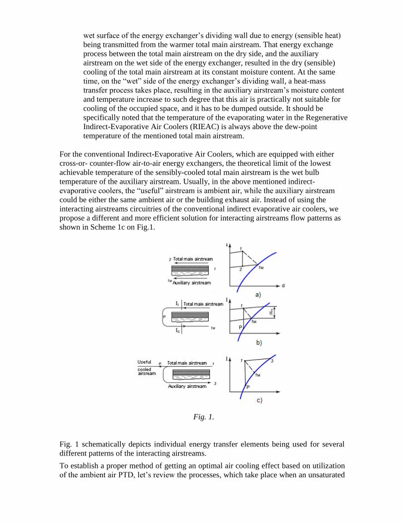
Fig. 1.
Fig. 1 schematically depicts individual energy transfer elements being used for several
different patterns of the interacting airstreams.
To establish a proper method of getting an optimal air cooling effect based on utilization
of the ambient air PTD, let’s review the processes, which take place when an unsaturated
airstream flows along the flat plate, one side of which is dry, while the opposite one is
permanently wet (see Scheme 1b on Fig. 1).
Let's also assume that the plate’s thermal resistance value is zero, the plate’s surface area
is infinite, and the heat exchange with circumambient is absent.
For the above assumed conditions, let’s evaluate three specific configurations of the
interacting airstreams (Schemes 1a, 1b and 1c on Fig.1) and define their applicability and
theoretical lowest temperature limit of the cooled airstreams:
Fig. 1а. The two interacting airstreams are at equal initial conditions and flowing
parallel to each other in the same direction along the flat surfaces of the heat-
mass-transfer element. The theoretical lowest limit temperature of the airstream
being dry cooled, is its wet bulb temperature.
Fig. 1b. The airstream to be cooled at first is moving along the dry heat transfer
surface of the plate and then, on the end of the plate, it makes a 1800 turn and
continues to flow along the wet side of the plate. Thus, the auxiliary airstream exits
the wet side of the plate at conditions, where values of its dry and wet bulb
temperatures become equal to each other and, at the same time, both are equal to
the wet bulb temperature of the intake air. In other words, the adiabatic air cooling
process takes place. The temperature difference between the airstreams on both
sides of the heat-mass transfer plate suggests that the heat flow moves from the
airstream moving along the dry surface of the plate to the air stream moving along
the wet side of the plate. The transmitted heat warms and evaporates water on the
wet side of the plate, resulting in cooling of air, which is moving along the dry side
of the plate. The water vapors are continuously swiped out and absorbed by the
moving wet airstream.
Fig 1c. The total main airstream is indirectly (sensibly) cooled (at its constant
moisture content d=const) on the dry side of the energy exchanger. After that, its
certain predetermined portion (an “auxiliary airstream”) is extracted, adiabatically
cooled on the wet side of the energy exchanger, and subsequently used for the
sensible cooling of the total main airstream.
Let’s denote enthalpies of the interacting airstreams as follows:
І1 - enthalpy of the ambient air at its dry & web bulb temperatures of t1db & t1wb*
respectively enter into the energy exchanger
Idp - enthalpy of the ambient air at its dew point temperature
I2 - enthalpy of the sensibly cooled total main airstream at its splitting point
І3 - enthalpy of the auxiliary airstream exiting wet side of the energy exchanger.
*t1db & t1wb are respectively dry bulb and wet bulb temperatures of the ambient air entering into dry channels of the
energy exchanger
From the energy balance equation І1 – Іdp = І2 – Іdp it follows that І1 = І2. Thus, the value
of the temperature difference between the dry and wet interacting airstreams, taken at any
cross-section point of the energy transfer plate, equals to the PTD of the air being dry
cooled.
Since the main airstream, moving along the dry heat transfer surface, is being cooled at
its constant moisture content, the temperature difference value between the interacting
airstreams across the energy transfer plate at the air’s splitting/turning point would be
equal to “zero”. At the same time and at the same point, the dry bulb temperature of the
cooled airstream would reach its dew-point value.
Thus, with accepted assumptions, the total main airstream flowing along the dry side of
the energy transfer plate, while the opposite one is wet, is being cooled down to its dew-
point temperature, while the auxiliary airstream moving on the wet side of the plate is
increasing its moisture content and dry bulb temperature up to the parameters,
corresponding to the wet bulb temperature of the ambient air entering the dry side of the
energy transfer plate. The series of conducted experiments have proven the above
statements. The test data of the experiments is presented in the Tables 1A (SI Units) and
1B (British Units) below.
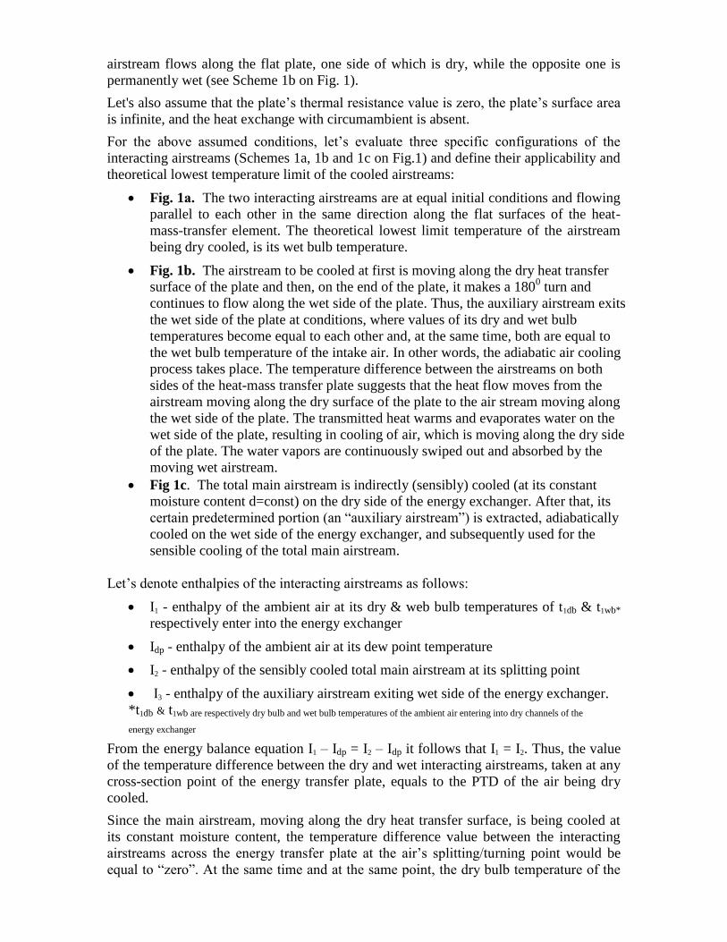
Table 1A (SI Units)
№
№ of
test
regime
Parameters of the Interacting Airstreams of the Regenerative
Indirect Evaporative Air Cooler Air
velocity
in dry &
wet
channels
Total main
airstream entering
dry side of the
energy exchanger
Total main cooled
airstream at the
splitting point of
the energy
exchanger
(air turning point)
Auxiliary airstream
exiting the wet side
of energy
exchanger
t1db,
ºC
t1wb,
ºC
d1,
g/kg
t2db
ºC
t2wb,
ºC
d2,
g/kg
t3db,
ºC
t3wb,
ºC
d3,
g/kg V, m/s
1 40 35 17.1 4.9 7.2 3.6 4.9 24 17.3 10.6 2.8
2 42 30.1 16.8 6.3 10.1 7.6 6.3 20 17.1 11 3.0
3 46 40 18.5 6.5 10.2 8.0 6.5 23.8 18.8 14.3 3.0
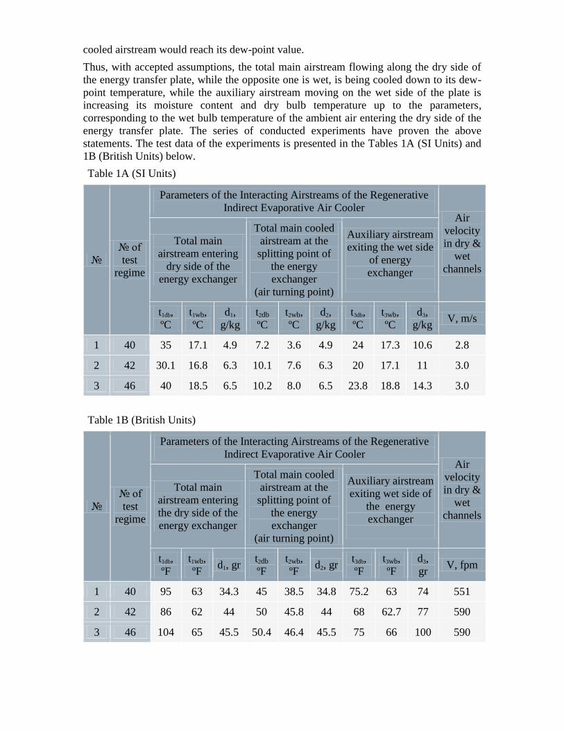
Table 1B (British Units)
№
№ of
test
regime
Parameters of the Interacting Airstreams of the Regenerative
Indirect Evaporative Air Cooler Air
velocity
in dry &
wet
channels
Total main
airstream entering
the dry side of the
energy exchanger
Total main cooled
airstream at the
splitting point of
the energy
exchanger
(air turning point)
Auxiliary airstream
exiting wet side of
the energy
exchanger
t1db,
ºF
t1wb,
ºF d1, gr
t2db
ºF
t2wb,
ºF d2, gr
t3db,
ºF
t3wb,
ºF
d3,
gr V, fpm
1 40 95 63 34.3 45 38.5 34.8 75.2 63 74 551
2 42 86 62 44 50 45.8 44 68 62.7 77 590
3 46 104 65 45.5 50.4 46.4 45.5 75 66 100 590
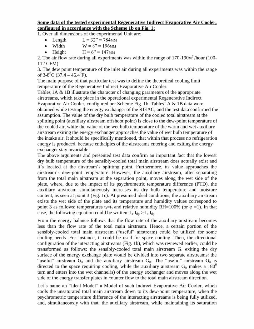
Some data of the tested experimental Regenerative Indirect Evaporative Air Cooler,
configured in accordance with the Scheme 1b on Fig. 1:
1. Over all dimensions of the experimental Unit are:
Length L = 32” = 784мм
Width W = 8” = 196мм
Height Н = 6” = 147мм
2. The air flow rate during all experiments was within the range of 170-190м3 /hour (100-
112 CFM).
3. Тhe dew point temperature of the inlet air during all experiments was within the range
of 3-80C (37.4 – 46.4
0F).
The main purpose of that particular test was to define the theoretical cooling limit
temperature of the Regenerative Indirect Evaporative Air Cooler.
Tables 1A & 1B illustrate the character of changing parameters of the appropriate
airstreams, which take place in the operational experimental Regenerative Indirect
Evaporative Air Cooler, configured per Scheme Fig. 1b. Tables’ A & 1B data were
obtained while testing the energy exchanger of the RIEAC, and the test data confirmed the
assumption. The value of the dry bulb temperature of the cooled total airstream at the
splitting point (auxiliary airstream offshoot point) is close to the dew-point temperature of
the cooled air, while the value of the wet bulb temperature of the warm and wet auxiliary
airstream exiting the energy exchanger approaches the value of wet bulb temperature of
the intake air. It should be specifically mentioned, that within that process no refrigeration
energy is produced, because enthalpies of the airstreams entering and exiting the energy
exchanger stay invariable.
The above arguments and presented test data confirm an important fact that the lowest
dry bulb temperature of the sensibly-cooled total main airstream does actually exist and
it’s located at the airstream’s splitting point. Furthermore, its value approaches the
airstream’s dew-point temperature. However, the auxiliary airstream, after separating
from the total main airstream at the separation point, moves along the wet side of the
plate, where, due to the impact of its psychrometric temperature difference (PTD), the
auxiliary airstream simultaneously increases its dry bulb temperature and moisture
content, as seen at point 3 (Fig. 1c). At presumed ideal conditions, the auxiliary airstream
exists the wet side of the plate and its temperature and humidity values correspond to
point 3 as follows: temperatures t1=t3 and relative humidity RH=100% (or φ =1). In that
case, the following equation could be written: I3-Idp > I1-Idp.
From the energy balance follows that the flow rate of the auxiliary airstream becomes
less than the flow rate of the total main airstream. Hence, a certain portion of the
sensibly-cooled total main airstream (“useful” airstream) could be utilized for some
cooling needs. For instance, it could be used for space cooling. Then, the directional
configuration of the interacting airstreams (Fig. 1b), which was reviewed earlier, could be
transformed as follows: the sensibly-cooled total main airstream GT exiting the dry
surface of the energy exchange plate would be divided into two separate airstreams: the
“useful” airstream Go and the auxiliary airstream GB. The “useful” airstream Go is
directed to the space requiring cooling, while the auxiliary airstream GB makes a 1800
turn and enters into the wet channel(s) of the energy exchanger and moves along the wet
side of the energy transfer plates in counter flow to the total main airstream direction.
Let’s name an “Ideal Model” a Model of such Indirect Evaporative Air Cooler, which
cools the unsaturated total main airstream down to its dew-point temperature, when the
psychrometric temperature difference of the interacting airstreams is being fully utilized,
and, simultaneously with that, the auxiliary airstream, while maintaining its saturation
conditions, is gradually warming up, until its wet bulb temperature will approach the dry
bulb temperature of the intake air.
The “Gross Useful Cooling Capacity” Qid
o of the Ideal Model could be expressed by the
equation (1):
Qid
o = (Gid
o) (І1 – Іdp) (1)
Where:
Gid
o – is a mass flow rate of the useful cooling airstream.
An Energy Balance equation for the Ideal Model could be written as follows:
(GT) (І1 – Іdp) = (Gid
в)·(І3 – Іdp ) (2)
Where:
GT - mass flow rate of the total main airstream
Gid
в - mass flow rate of the auxiliary airstream
Let’s establish such a parameter as the “Ideal Specific Mass Flow Rates Ratio” (Мid
),
which represents a ratio between the mass flow rates of the useful and the total main
airstreams:
Мid
= Gid
o / Gid
T
Replacement members in the equations Мid
with their meanings taken from the equations
(1) and (2) would change the equation as follows:
Мid
= Gid
o / Gid
T = (І3 – І1) / (І3 – Іdp) (3)
The Мid
defines a portion of the total main sensibly-cooled airstream (or useful cooling
airstream), which could be used for the space (or other purpose) cooling.
From the equation (1) follows:
Qid
o = (Gid
o) (І1 – Іdp) = (Gв) (І3 – І1)
Then
Мid
= (Gid
в) (І3 – І1) / (Gid
в) (І3 – Іdp) = (Qid
o) / (QT) (4)
Thus, the Мid
characterizes potential cooling capabilities of the ambient air at given
temperature and moisture content, and, as it follows from equation (3), its value depends
only on the air’s initial conditions.
Since the values of the dry bulb temperatures of the interacting total main and auxiliary
airstreams are equal to each other at each and any cross-section of the Ideal Model’s
energy exchanger and the water evaporates into the saturated airstream, then, the heat and
moisture transfer processes are proceeding quasi-statically, and it may be assumed that
they are reversible. Therefore, according to the Second Law of Thermodynamics, it
should maintain the following equality:
(ΣSout) / (ΣSin) = 1 (5)
Where:
ΣSout and ΣSin are respectively sums of the system’s output and input entropies,
i.e. the entropy S of the mentioned cooling process is unchangeable.
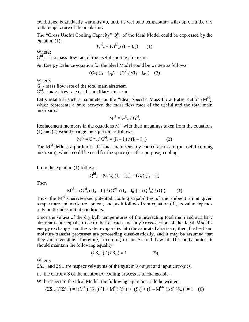
With respect to the Ideal Model, the following equation could be written:
(ΣSout)/(ΣSin) = [(Мid
)·(Sdp)·(1 + Мid
) (S3)] / [(S1) + (1 – Мid
) (Δd) (Sw)] = 1 (6)
Where:
S1 – is the entropy of air at point 1 on diagram on Fig. 1b.
Sdp – is the entropy of air at point P on diagram on Fig. 1b.
S3 – is the entropy of air at point 3 on diagram on Fig. 1b.
Sw – is the entropy of the water vapors at point 3 on diagram of Fig. 1b.
Δd – is the difference between air moisture content at points 1 and 3 in diagram Fig. 1b.
The calculations performed, based on equation (6) for the various initial conditions of the
ambient air, have shown that the obtained absolute values of the equation (6) are within
the range of 1.007 ÷ 1.002. These results validate the assumption that the heat-mass
exchange processes, occurring in the Ideal Model, are reversible. This allows achieving
of the maximum air cooling effect via evaporating water into the unsaturated auxiliary
airstream at the minimal energy and material consumption. Hence, the value of the
thermodynamic perfection of the Ideal Model equals 1.0.
All of the above discussions, analysis, and conclusions combined together allowed
establishing limiting capabilities of the Indirect-Evaporative Air Cooling Method, and
they could be applied as a reference standard for any device of that kind.
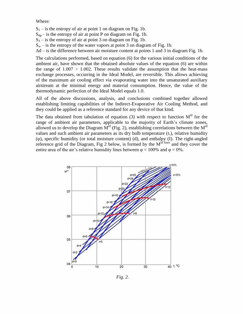
The data obtained from tabulation of equation (3) with respect to function Мid
for the
range of ambient air parameters, applicable to the majority of Earth’s climate zones,
allowed us to develop the Diagram Мid
(Fig. 2), establishing correlations between the Мid
values and such ambient air parameters as its dry bulb temperature (t1), relative humidity
(φ), specific humidity (or total moisture content) (d), and enthalpy (I). The right-angled
reference grid of the Diagram, Fig 2 below, is formed by the Мid lines
and they cover the
entire area of the air’s relative humidity lines between φ = 100% and φ = 0%.
Fig. 2.
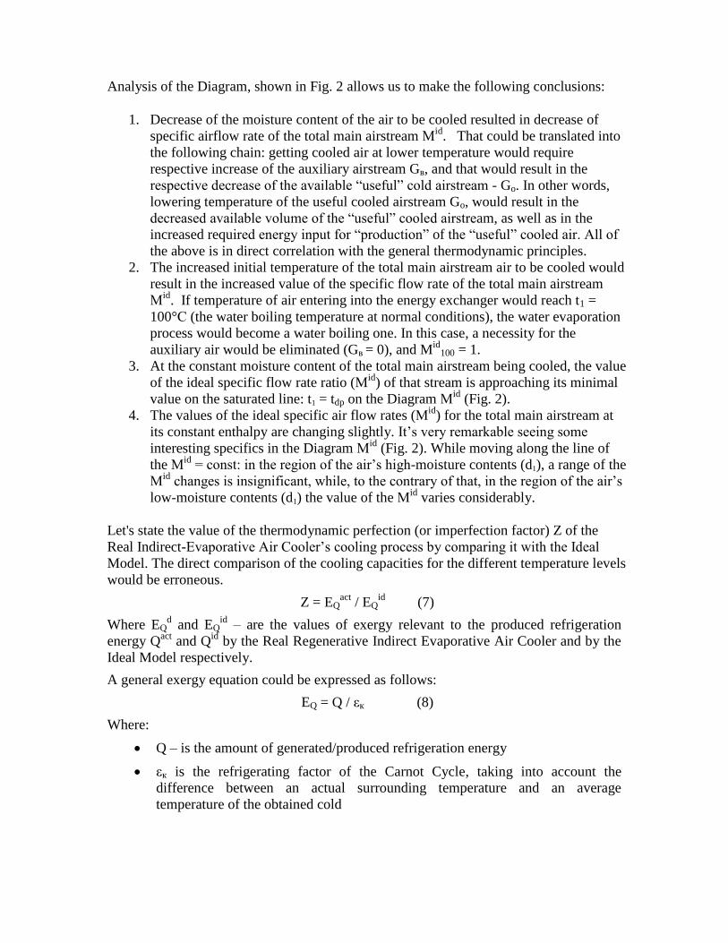
Analysis of the Diagram, shown in Fig. 2 allows us to make the following conclusions:
1. Decrease of the moisture content of the air to be cooled resulted in decrease of
specific airflow rate of the total main airstream Мid
. That could be translated into
the following chain: getting cooled air at lower temperature would require
respective increase of the auxiliary airstream Gв, and that would result in the
respective decrease of the available “useful” cold airstream - Go. In other words,
lowering temperature of the useful cooled airstream Go, would result in the
decreased available volume of the “useful” cooled airstream, as well as in the
increased required energy input for “production” of the “useful” cooled air. All of
the above is in direct correlation with the general thermodynamic principles.
2. The increased initial temperature of the total main airstream air to be cooled would
result in the increased value of the specific flow rate of the total main airstream
Мid
. If temperature of air entering into the energy exchanger would reach t1 =
100°С (the water boiling temperature at normal conditions), the water evaporation
process would become a water boiling one. In this case, a necessity for the
auxiliary air would be eliminated (Gв = 0), and Mid
100 = 1.
3. At the constant moisture content of the total main airstream being cooled, the value
of the ideal specific flow rate ratio (Мid
) of that stream is approaching its minimal
value on the saturated line: t1 = tdp on the Diagram Мid
(Fig. 2).
4. The values of the ideal specific air flow rates (Мid
) for the total main airstream at
its constant enthalpy are changing slightly. It’s very remarkable seeing some
interesting specifics in the Diagram Мid
(Fig. 2). While moving along the line of
the Мid
= const: in the region of the air’s high-moisture contents (d1), a range of the
Мid
changes is insignificant, while, to the contrary of that, in the region of the air’s
low-moisture contents (d1) the value of the Мid
varies considerably.
Let's state the value of the thermodynamic perfection (or imperfection factor) Z of the
Real Indirect-Evaporative Air Cooler’s cooling process by comparing it with the Ideal
Model. The direct comparison of the cooling capacities for the different temperature levels
would be erroneous.
Z = EQact
/ EQid
(7)
Where EQd and EQ
id – are the values of exergy relevant to the produced refrigeration
energy Qact
and Qid
by the Real Regenerative Indirect Evaporative Air Cooler and by the
Ideal Model respectively.
A general exergy equation could be expressed as follows:
EQ = Q / εк (8)
Where:
Q – is the amount of generated/produced refrigeration energy
εк is the refrigerating factor of the Carnot Cycle, taking into account the
difference between an actual surrounding temperature and an average
temperature of the obtained cold
A substitution of some appropriate members in expression (8) with their matching
meanings would result in the following:
EQact
= [(Сp)·(Goact
) (Т1 – Т2)2] / (Т1 + Т2) (9)
EQid
= (Сp)·(Goid
) (Т1 – Т2)2 / (Т1 + Тdp) (10)
where:
Сp - Specific Heat of air at pressure P (in our case P = atmospheric pressure),
kcal/(kg)(10C temperature change)
Т1 - is the initial temperature of the total main airstream entering into the energy
exchanger, 0K
Т2 – is the final temperature of the cooled total main airstream exiting the energy
exchanger, 0K
Тdp – is the Dew Point temperature of the total main airstream within the dry
side of the energy exchanger, 0K
Then:
Z = (Goact
/Goid
) ((Т1 – Т2) / ((Т1 – Тdp)2) ((Т1 + Тdp) / (Т1 + Т2)) (11)
The first multiplier in equation (11) - (Goact
/Goid
) defines a ratio between the mass flow
rates of the Actual and Ideal useful cooled airstreams at equal values of the Actual and
Ideal total main airstreams, (GT
act = GT
id).
So, the ratio of the Ideal and Actual useful cooled airstreams could be expressed as
follows:
Λ = (Goact
/GT) / (Goid
/GT) = Mact
/ Mid
(12)
As it was mentioned earlier, the theoretical minimal temperature limit of the total cooled
main airstream is its dew-point temperature. Hence, the second multiplier
((Т1 – Т2) / (Т1 – Тdp)) in the equation (11) represents an effectiveness ratio (or
temperature approaching factor) Еdp of the air cooling process relevant to the dew point
temperature of the total main airstream. So, the temperature approaching factor could be
expressed as follows:
Еdp = (Т1 – Т2) / (Т1 – Тdp) (13)
For the range of the ambient air parameters near-Earth-surface typical and applicable for
most of the Globe’s climate zones, the numeric value of the third multiplier in the
equation (11) is 1.0 and as follows:
(Т1 + Тdp) / (Т1 + Т2) ≈ 1.0 (14)
Then, after proper substitution, the equation (11) of the thermodynamic perfection is
transformed into equation below (15):
Z = Λ Е2
dp (15)
So, the extent of thermodynamic perfection considers influence of the two following
factors: the quantity of the “useful” cooled airstream, which could be utilized for the
active cooling needs and the operating performance efficiency of the IEAC. The equation
(15) is suitable for estimation of the thermodynamic perfection of any type of the
indirect-evaporative air coolers.
At equal conditions of the ambient air, the extent of the thermodynamic perfection Z for
the RIEAC would exceed the ones for the other comparable indirect evaporative air
coolers.
In case when the cooling space requires more comfortable (lower humidity) air
conditions, or when the process cooling application prohibits elevated moisture content
of the cooling airstream, the IEAC unit should be equipped only with the sensible cooling
stage (the energy exchanger), which provides dry cooling of the total main and “useful”
airstreams.
For boosting of the cooling output of the IEAC (in cases when the elevated humidity for
the non-comfort space and process-cooling application is allowed), the lower dry bulb
temperature of the sensibly-cooled discharged air could be achieved by means of
installing downstream of the first-dry cooling stage (the energy exchanger) of the IEAC
of an additional adiabatic air cooling section, i.e. converting the Unit into the two-stage
Indirect-Direct Evaporative Air Cooler.
For the effective operation of the regenerative indirect-evaporative air coolers in the
regions with high–humidity ambient air, the units could be integrated with the inlet
(ambient) air drying module. This combination allows to significantly bring down the dry
bulb temperature (down to +5ºС ÷ +7°С) as well as moisture content of the discharge
cooled air. This approach is greatly expands the area of applications of that method,
allowing use of this cooling technology for the controllable comfort space and process
cooling. For instance, it could be used for cooling of juicy vegetative raw materials and
other products, which do not require freezing temperatures for storage.
The conducted experiments of that hybrid unit have demonstrated that the total main
airstream at its inlet moisture content of d <2 g/kg could be cooled down to as low as 4-
6°Сdb temperature.
Therefore, it could be stated, that the Performance Efficiency and Economics of the
“pure” (without using any additional air drying means) Indirect-Evaporative Air Cooling
Technology defines possibilities of its wide practical applications, which largely depend
on the initial moisture content (or dew-point temperature) of the intake air.
The Indirect Evaporative Air Cooler during summer time is able to provide the indoor air
temperature within 25-28°Сdb range at the corresponding relative humidity of ≤60 % if
the value of the outdoor air moisture content (d) does not exceed 13g/kg.
At the considerable levels of the ambient air moisture content it is necessary to use either
conventional refrigeration or Regenerative Indirect Evaporative Air Coolers equipped
with the air pre-drying means.
Another important factor defining expediency of use of the Regenerative Indirect
Evaporative Air Coolers (RIEAC), is their overall performance efficiency being
characterized by parameter ξ (Energy Efficiency Ratio), which is a ratio between the net
heat assimilating (cooling) capacity (Qncc) of the unit and the total power input (TPI) into
the operational Unit, including power draw by the fan(s), water circulating pump,
controls, and misc.
ξ = Qncc / Ntpi (16)
Where:
N tpi –Total Power Input (TPI) into operating RIEAC, kW
Qncc – Net Cooling Capacity (NCC) of the useful cooled supply airstream, kW

Qncc = (Goact
) (Iactindoor - I2), kW
Where:
Iactindoor – an actual enthalpy of the indoor air of the space being served by the RIEAC.
I2 - Enthalpy of the cooled total main air stream leaving the dry side of the energy
exchanger
The fan’s total pressure should be adequate for overcoming the resistance of all internal
components (dry and wet sides of the energy exchanger and air pre-filter, etc.) of the
RIEAC as well as providing a required external static pressure necessary for overcoming
a resistance of the air distribution system, as well as a certain room back pressure, while
delivering required volume of the cooled air down to the cooling space.
Total power draw (fan motor + pump motor + controls + misc. power) by the operating
RIEAC Unit:
Ntpi = N fan mot + Npump mot + Ncontr. + Nmisc
Where:
N fan mot - Power draw by fan motor, kW
Npump mot – Power draw by pump motor, kW
Ncontr. – Power draw by the onboard control system. kW
Nmisc – Power draw by the misc. electrical components, kW
A value of the Energy Efficiency Ratio (ξ) primarily depends on a moisture content of the
dry-cooled total main airstream. Table-2 presents the test values of the respective Energy
Efficiency Ratios (ξ) being obtained for the constant air dry bulb temperature of 32ºС
(entering the energy exchanger) at various moisture contents.
Table-2
Inlet air’s moisture content, g/kg 2 4 6 8 10 12
Energy Efficiency Ratio, ξ 24 19 15.6 12.5 10 8.2
Fig.3 Chart below illustrates a correlation between the temperature of the cooled total
main airstream exiting the energy exchanger and the inlet air’s moisture content. During
that test the airstream’s entering dry bulb temperature was maintained constant at 40ºС at
varying moisture content.
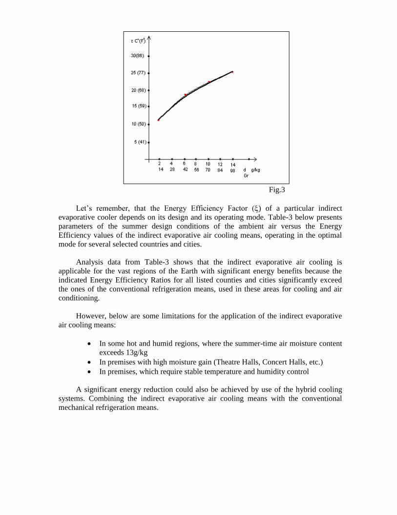
Fig.3
Let’s remember, that the Energy Efficiency Factor () of a particular indirect
evaporative cooler depends on its design and its operating mode. Table-3 below presents
parameters of the summer design conditions of the ambient air versus the Energy
Efficiency values of the indirect evaporative air cooling means, operating in the optimal
mode for several selected countries and cities.
Analysis data from Table-3 shows that the indirect evaporative air cooling is
applicable for the vast regions of the Earth with significant energy benefits because the
indicated Energy Efficiency Ratios for all listed counties and cities significantly exceed
the ones of the conventional refrigeration means, used in these areas for cooling and air
conditioning.
However, below are some limitations for the application of the indirect evaporative
air cooling means:
In some hot and humid regions, where the summer-time air moisture content
exceeds 13g/kg
In premises with high moisture gain (Theatre Halls, Concert Halls, etc.)
In premises, which require stable temperature and humidity control
A significant energy reduction could also be achieved by use of the hybrid cooling
systems. Combining the indirect evaporative air cooling means with the conventional
mechanical refrigeration means.
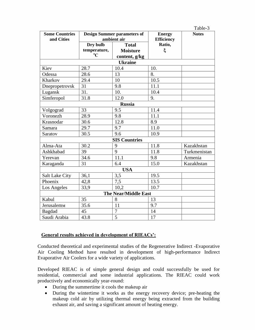
Table-3
Some Countries
and Cities
Design Summer parameters of
ambient air
Energy
Efficiency
Ratio,
Notes
Dry bulb
temperature, оС
Total
Moisture
content, g/kg
Ukraine
Kiev 28.7 10.4 10.
Odessa 28.6 13 8.
Kharkov 29.4 10 10.5
Dnepropetrovsk 31 9.8 11.1
Lugansk 31. 10. 10.4
Simferopol 31.8 12.0 9.
Russia
Volgograd 33 9.5 11.4
Voronezh 28.9 9.8 11.1
Krasnodar 30.6 12.8 8.9
Samara 29.7 9.7 11.0
Saratov 30.5 9.6 10.9
SIS Countries
Alma-Ata 30.2 9 11.8 Kazakhstan
Ashkhabad 39 9 11.8 Turkmenistan
Yerevan 34.6 11.1 9.8 Armenia
Karaganda 31 6.4 15.0 Kazakhstan
USA
Salt Lake City 36,1 3,5 19.5
Phoenix 42,8 7,5 13.5
Los Angeles 33,9 10,2 10.7
The Near/Middle East
Kabul 35 8 13
Jerusalemм 35.6 11 9.7
Bagdad 45 7 14
Saudi Arabia 43.8 5 17
General results achieved in development of RIEACs’:
Conducted theoretical and experimental studies of the Regenerative Indirect -Evaporative
Air Cooling Method have resulted in development of high-performance Indirect
Evaporative Air Coolers for a wide variety of applications.
Developed RIEAC is of simple general design and could successfully be used for
residential, commercial and some industrial applications. The RIEAC could work
productively and economically year-round:
During the summertime it cools the makeup air
During the wintertime it works as the energy recovery device; pre-heating the
makeup cold air by utilizing thermal energy being extracted from the building
exhaust air, and saving a significant amount of heating energy.
Some examples of RIEAC applications
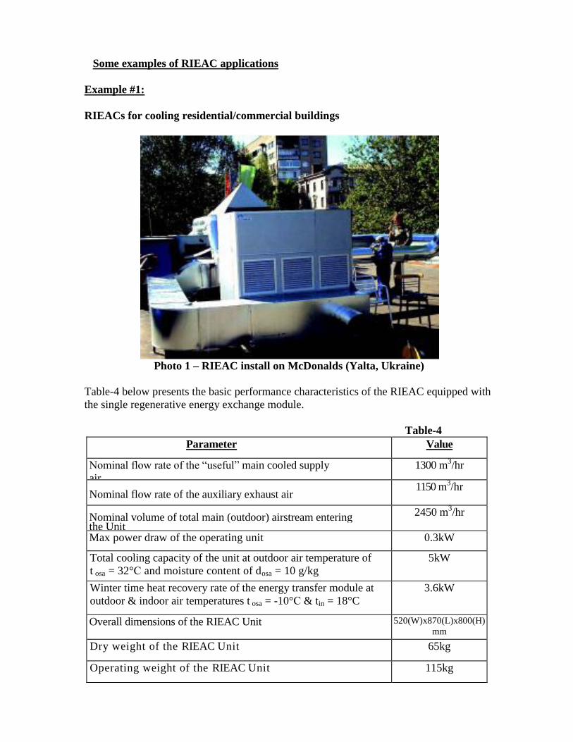
Example #1:
RIEACs for cooling residential/commercial buildings
Photo 1 – RIEAC install on McDonalds (Yalta, Ukraine)
Table-4 below presents the basic performance characteristics of the RIEAC equipped with
the single regenerative energy exchange module.
Table-4
Parameter Value
Nominal flow rate of the “useful” main cooled supply
air
aairstreamairm3/hr
1300 m3/hr
Nominal flow rate of the auxiliary exhaust air
m
3/hr
1150 m3/hr
Nominal volume of total main (outdoor) airstream entering the Unit
2450 m3/hr
Max power draw of the operating unit 0.3kW
Total cooling capacity of the unit at outdoor air temperature of
t osa = 32°С and moisture content of dosa = 10 g/kg
5kW
Winter time heat recovery rate of the energy transfer module at
outdoor & indoor air temperatures t osa = -10°С & tin = 18°C
Res
3.6kW
Overall dimensions of the RIEAC Unit 520(W)x870(L)x800(H)
mm
Dry weight of the RIEAC Unit 65kg
Operating weight of the RIEAC Unit 115kg
Notes:
A number of the regenerative energy exchange modules within the RIEAC other
than indicated capacities in Table 3, as well the RIEAC design configuration
should be determined for specific application and design conditions.
In cases, when the localized building’s exhaust air is available and its wet bulb
temperature is lower than the wet bulb temperature of the RIEAC’, that air could
be introduced into the wet channels of the energy exchanger instead of the regular
auxiliary airstream. This would result in increased efficiency of the RIEAC.
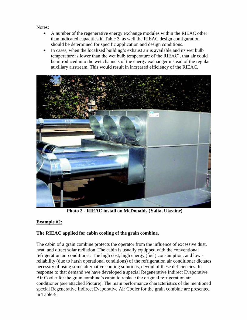
Photo 2 - RIEAC install on McDonalds (Yalta, Ukraine)
Example #2:
The RIEAC applied for cabin cooling of the grain combine.
The cabin of a grain combine protects the operator from the influence of excessive dust,
heat, and direct solar radiation. The cabin is usually equipped with the conventional
refrigeration air conditioner. The high cost, high energy (fuel) consumption, and low -
reliability (due to harsh operational conditions) of the refrigeration air conditioner dictates
necessity of using some alternative cooling solutions, devoid of these deficiencies. In
response to that demand we have developed a special Regenerative Indirect Evaporative
Air Cooler for the grain combine’s cabin to replace the original refrigeration air
conditioner (see attached Picture). The main performance characteristics of the mentioned
special Regenerative Indirect Evaporative Air Cooler for the grain combine are presented
in Table-5.
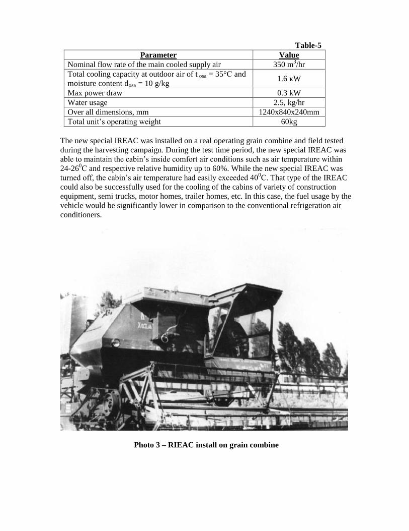
Table-5
Parameter Value
Nominal flow rate of the main cooled supply air 350 m3/hr
Total cooling capacity at outdoor air of t osa = 35°С and
moisture content dosa = 10 g/kg 1.6 кW
Max power draw 0.3 kW
Water usage 2.5, kg/hr
Over all dimensions, mm 1240x840x240mm
Total unit’s operating weight 60kg
The new special IREAC was installed on a real operating grain combine and field tested
during the harvesting campaign. During the test time period, the new special IREAC was
able to maintain the cabin’s inside comfort air conditions such as air temperature within
24-260С and respective relative humidity up to 60%. While the new special IREAC was
turned off, the cabin’s air temperature had easily exceeded 400С. That type of the IREAC
could also be successfully used for the cooling of the cabins of variety of construction
equipment, semi trucks, motor homes, trailer homes, etc. In this case, the fuel usage by the
vehicle would be significantly lower in comparison to the conventional refrigeration air
conditioners.
Photo 3 – RIEAC install on grain combine
Example #3:
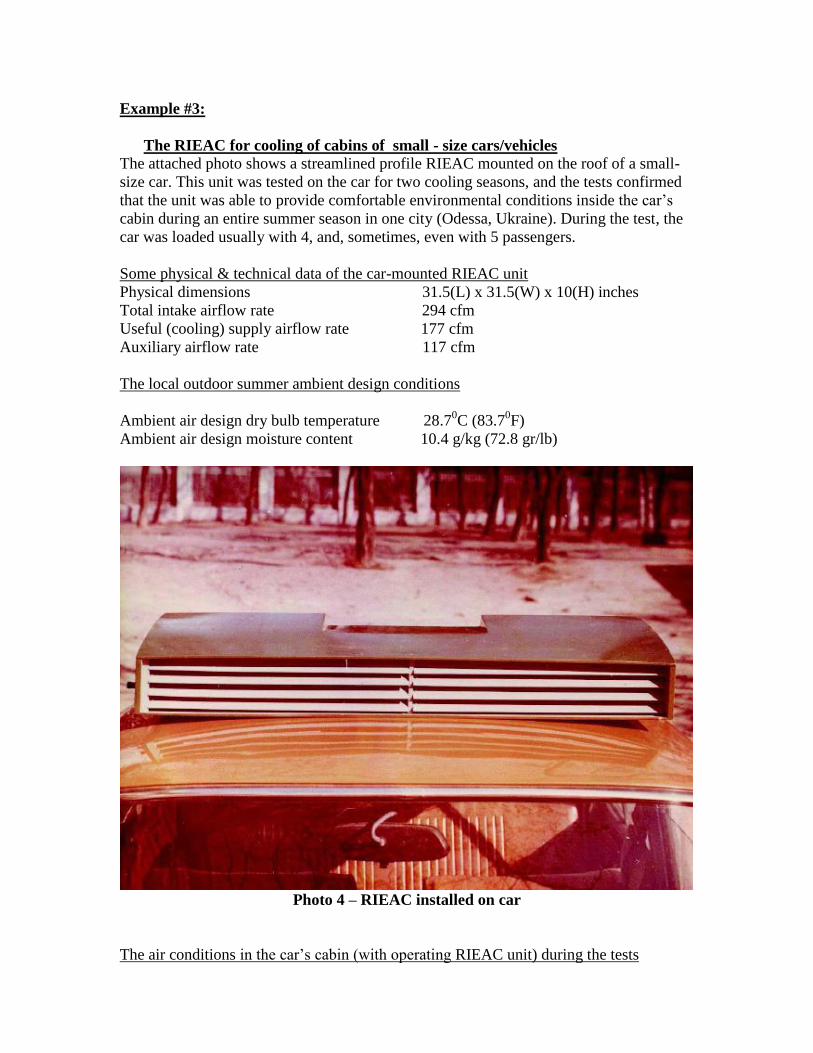
The RIEAC for cooling of cabins of small - size cars/vehicles
The attached photo shows a streamlined profile RIEAC mounted on the roof of a small-
size car. This unit was tested on the car for two cooling seasons, and the tests confirmed
that the unit was able to provide comfortable environmental conditions inside the car’s
cabin during an entire summer season in one city (Odessa, Ukraine). During the test, the
car was loaded usually with 4, and, sometimes, even with 5 passengers.
Some physical & technical data of the car-mounted RIEAC unit
Physical dimensions 31.5(L) x 31.5(W) x 10(H) inches
Total intake airflow rate 294 cfm
Useful (cooling) supply airflow rate 177 cfm
Auxiliary airflow rate 117 cfm
The local outdoor summer ambient design conditions
Ambient air design dry bulb temperature 28.70C (83.7
0F)
Ambient air design moisture content 10.4 g/kg (72.8 gr/lb)
Photo 4 – RIEAC installed on car
The air conditions in the car’s cabin (with operating RIEAC unit) during the tests
An average discharge temperature of “useful” (cooled) air 17-180C (66.2-64.4
0F)
The cabin’s air dry bulb temperature range 26-270C (78.8 – 80.6
0F)
The cabin’s air RH range……………………….55-60%
Conclusions: 1. Extensive R&D resulted in development of a new type of an advanced air cooler –
the Regenerative Indirect Evaporative Air Cooler, which provides maximum
evaporative air cooling effect at a minimum power and water inputs.
2. Extensive studies and analysis of the statistical climate data with respect to
ambient air moisture content levels for the major world regions showed a
possibility of applying the RIEACs without air drying means for providing optimal
and/or admissible parameters of indoor air in premises within these territories
(excluding the tropical and subtropical wet zones).
3. The Thermo-physical Lab had patented, designed, developed, and fabricated
experimental RIEACs of different capacities and configurations for different
applications. The results of extensive laboratory and field testing of the mentioned
IREAC have confirmed that the actual performance characteristics and
characteristics established theoretically are very close in value.
4. The technology of the RIEACs is mature and ready for Global use.
Notes: 1. Continued and extensive R&D has resulted in development of the newest approaches to the Indirect
Evaporative Air Technology and Equipment (with and without the air drying means,) which
significantly outperforms all known equipment of that kind on the market. Information on these
developments is not presented in this article. 2. Currently the TT - Group (Ukraine) has established manufacturing and installations of various
(customized) types of the RIEACs.
Some major advantages of the RIEACs are:
Pollution-free operation.
The RIEACs supply 100% of “fresh” cooled air into the servicing space, while the
conventional refrigeration air conditioners usually re-circulate at least 90% of the
indoor air. Therefore, it provides much healthier indoor environmental conditions
(no indoor micro-flora, mildew, mold, odors, etc.).
The RIEACs are highly-economical: at significantly lower power consumption.
Their discharge air temperature is just slightly higher that the one from the
conventional refrigeration air conditioners.
The RIEACs’ simple single-fan modular design translates into relatively low
manufacturing cost at mass production, low operating and maintenance costs, as
well as low-labor requirements at units’ factory assembly and/or their field
modification. The RIEACs could also be easily integrated into the existing air
conditioning and ventilating systems, and significantly improve their overall
performance efficiency.
The RIEACs could be successfully used for either stationary or mobile
applications for year-round operations, providing summer cooling/pre-cooling
and/or winter pre-heating of the makeup air by means of recovering heat from the
warmer building or process exhaust.
List of publications and Patents:
1. A.B.Tsymerman, R.S.Lejdiker, J.Z.Falikson. The USSR copyright certificate
407519, “Indirect-evaporative air cooling unit” Published in BI, 1977, №23.
2. A.B.Tsymerman, R.S.Lejdiker, J.Z.Falikson. The USSR copyright certificate
407520. “Indirect-evaporative air cooler”. Published in BI, 1977, №23.
3. A.Tsymerman. About the optimal use of air psychrometric temperature difference
for air cooling. Engineering - Technical Journal, volume XXXIV, Minsk, 1978,
№3, p. 542.
4. A.B. Tsymerman, US Patent 5,212,956, “METHOD AND APPARATUS FOR
GAS COOLING”.
5. A.B. Tsymerman, US Patent 5,349,829, “METHOD AND APPARATUS FOR
EVAPORATIVELY COOLING GASES AND/OR FLUIDS”.
6. A.B. Tsymerman, US Patent 5,460,004, “DESICCANT COOLING SYSTEM
WITH EVAPORATIVE COOLING”.
7. Tsymerman A.B., Vartovoy V.A., Vartovoy D.V., Ukrainian Patent №58983A,
“Indirect Evaporative Cooling“.
8. Tsymerman A.B., Vartovoy V.A., Vartovoy D.V., Ukranian Patent №70434А,
“Air Conditioning Unit”.
9. A.Tsymerman, I.Jakovenko. A method of evaporative air cooling: Technology,
advantages, prospectives. Heating, Water Supply and Ventilation Magazine, №1
2004. Published by the Open Company «ID BAUbusiness».
10. I.Jakovenko, E.Solovtsov, A.Tsymerman, “New Indirect-Evaporative Air Cooler
(KIRUS)”, №3 2005. Published by the Open Company «ID BAUbusiness».
Information about the authors:
Dr. Tsymerman A.B. is a Director of the Thermo-physical Lab. He is the world-
known authority in the area of the non-refrigeration cooling and relevant methods
and technologies, holding over 100 national and international patents. Dr.
Tsymerman had received his MSME degree in Refrigeration Technologies from the
Odessa State Academy of Refrigeration Technologies in 1956. In 1985 he had
received his PHD degree from the Odessa State Academy of Refrigeration
Technologies. The thesis of his dissertation was “Theory and practical realization of
the Regenerative Indirect Evaporative Cooling Method”. Dr. Tsymerman A.B. is a
founder and Director of the Thermo-physical Lab.
Mr. Mike Reytblat, CPE had received his MS degree in Naval Engineering from the
Odessa Naval Engineering Academy in 1956, and his MSME degree in HVAC and
Gas Supply from the Odessa State University of Engineering and Construction in
1964. Currently Mr. Reytblat is Executive Vice President of Engineering and Chief
Scientist of R4 Ventures LLC in Scottsdale, AZ.
Authors could be reached at email address [email protected]