tl103029 telma replacement on meritor - welcome to … · page 1 of 10 29-jul-11 tl103029...
TRANSCRIPT
www.TelmaUSA.com Page 1 of 10 29-JUL-11
TL103029(TIL03029)
REPAIR MANUAL
Telma model FN72-40 replacement on Arvin Meritor forward tandem carrier
www.TelmaUSA.com Page 2 of 10 29-JUL-11
TL103029(TIL03029)
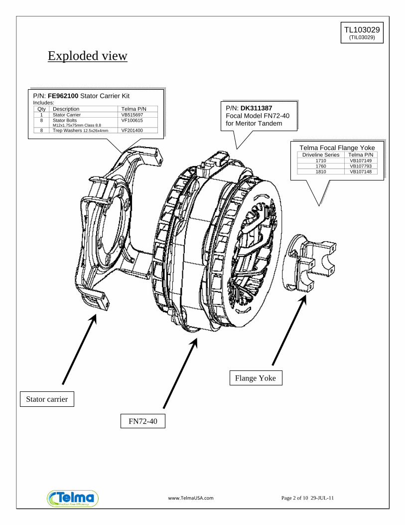
Exploded view
Stator carrier
FN72-40
Flange Yoke
P/N: FE962100 Stator Carrier Kit Includes:
Qty Description Telma P/N 1 Stator Carrier VB515697 8 Stator Bolts
M12x1.75x75mm Class 8.8 VF100615
8 Trep Washers 12.5x26x4mm VF201400
P/N: DK311387 Focal Model FN72-40 for Meritor Tandem
Telma Focal Flange Yoke Driveline Series Telma P/N
1710 VB107149 1760 VB107793 1810 VB107148

www.TelmaUSA.com Page 3 of 10 29-JUL-11
TL103029(TIL03029)
Disassembly 1. Remove the drive shaft and flange yoke from the Telma (See Step 14 for parts list)
2. Support the Telma with a suitable transmission jack
3. Remove the four countersunk 5/8” 12-point-head bolts holding the rotor spacer to the companion flange
4. Remove the 8 stator bolts holding the stator to the stator carrier
5. Lift the Telma assembly off the pilot of the companion flange and move the Telma assembly
towards the front of the truck to clear the axle and remove from under the vehicle.
6. If the stator carrier is replaced, remove the 7 bolts attaching the stator carrier to the input shaft bearing cover and remove the stator carrier from under the vehicle. (see notes on next page)
Hex Head Stator Securing Screw M12x1.75x75mm GR 10.9 Telma P/N: VF100615
Trep Washer 12.5x26x4 Telma P/N: VF201400
Rotor Spacer to Companion Flange Bolt 5/8” 12pt – 18 UNF x 3.5” GR 8 Telma P/N: TIF04075
Hardened Washer 1.06x0.66x0.09 Telma P/N: TIF04030
Hex Head Stator Carrier to Bearing Cage Bolt M12x1.75x75mm GR 10.9 Telma P/N: VF100615
Hardened Bearing Cage Washer 0.88x0.53x0.09 Meritor P/N: 1229U1511
Meritor Companion Flange RD/RP160 FLANGE A 3260E1877 RD145 FLANGE A 3260K1883 RP145 FLANGE A 3260L1884

www.TelmaUSA.com Page 4 of 10 29-JUL-11
TL103029(TIL03029)
Step 6 continued Note 1: Put a screw driver in the small gap between the bottom of the front rotor and the stator and pry back and forth to check for excess axial or radial play in the rotor assembly. If there is evidence of stator-to-rotor contact or excess rotor play, the input shaft nut and washer should be removed to check for movement of the companion flange on the input shaft splines as stated in the detailed inspection section of TP-0583. Check the flange for looseness or worn splines. If the flange slides on the shaft call ArvinMeritor OnTrac Technical Support Center at 866-668-7221 for assistance. The companion flange should be a press fit on the input shaft. Oil in the nut area may also indicate oil leaking through worn splines.
Note 2: Axle end play specification is 0.002” to 0.008”. Recommended end play is approximately 0.004”. To adjust end play, remove stator carrier and install cover using M12x1.75x45mm long bolts (Meritor P/N MS-212045-1) to hold cover in place while setting end play. Refer to pages from ArvinMeritor Maintenance Manual 5L in the appendix for details on how to adjust axle end play.
Note 3: Install new input shaft nut (Meritor P/N 40X1233) and washer (Meritor P/N 1229N1730). Apply Loctite 277 or 270 to the nut threads. Tighten nut to 750-850 lb-ft.
Assembly 1. To install the Telma stator carrier, align the holes of the stator carrier with the holes of the
bearing cage and install the seven M12 x 1.75 x 75mm bolts with Loctite patch (Meritor part number MS212075B2) and the seven M12 hardened washers (Meritor part number 1229U1511). Tighten all seven bearing cage bolts to 75-95 lb-ft (100-129 Nm).
2. Remove Telma focal assembly from the wooden crate.
3. Remove the four nuts and tabs used to secure the Telma during shipping, and discard.
4. Lift the Telma with a hoist and place it on a transmission jack. Be sure to properly support the
unit to avoid it from falling off the stand. The front side of the unit will have two clockwise arrows cast into the rotor face. The back side will mate up to the Telma stator carrier.
5. Remove an axle shaft or lift a wheel to allow the input shaft to rotate.
6. Lift the Telma in position and align the holes of the companion flange with the holes of the rotor spacer. Make sure all holes are lined up. Assemble the Telma to the companion flange with four 5/8-18 x 3.5” 12 pt. bolts with Loctite patch (Meritor part number SP1047) equipped with 5/8’ hardened flat washers (Meritor part number 1229U1503). Tighten to 180-230 lb-ft (245-310 Nm).
7. Rotate the stator so that the electrical connecting block is on the passenger side at the 10 O’clock position.
Remove and discard shipping fasteners
www.TelmaUSA.com Page 5 of 10 29-JUL-11
TL103029(TIL03029)
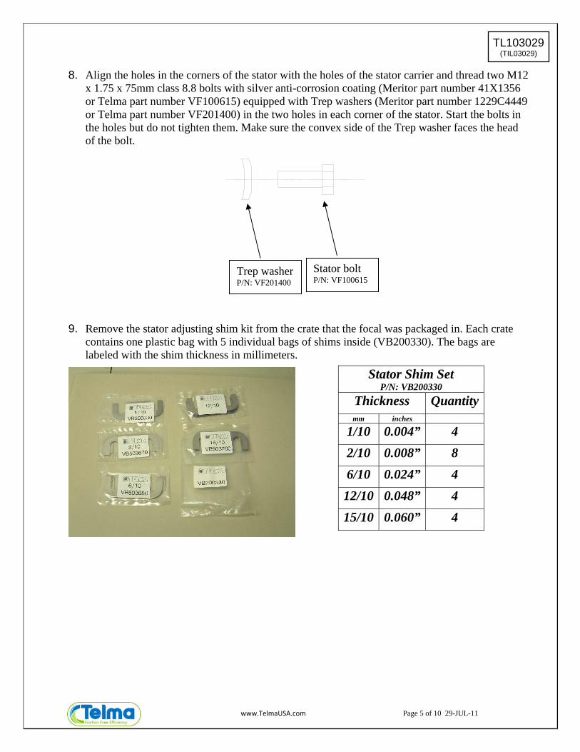
8. Align the holes in the corners of the stator with the holes of the stator carrier and thread two M12 x 1.75 x 75mm class 8.8 bolts with silver anti-corrosion coating (Meritor part number 41X1356 or Telma part number VF100615) equipped with Trep washers (Meritor part number 1229C4449 or Telma part number VF201400) in the two holes in each corner of the stator. Start the bolts in the holes but do not tighten them. Make sure the convex side of the Trep washer faces the head of the bolt.
9. Remove the stator adjusting shim kit from the crate that the focal was packaged in. Each crate contains one plastic bag with 5 individual bags of shims inside (VB200330). The bags are labeled with the shim thickness in millimeters.
Stator Shim Set P/N: VB200330
Thickness Quantitymm inches
1/10 0.004” 4
2/10 0.008” 8
6/10 0.024” 4
12/10 0.048” 4
15/10 0.060” 4
Trep washer P/N: VF201400
Stator bolt P/N: VF100615
www.TelmaUSA.com Page 6 of 10 29-JUL-11
TL103029(TIL03029)
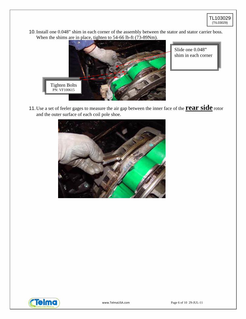
10. Install one 0.048” shim in each corner of the assembly between the stator and stator carrier boss. When the shims are in place, tighten to 54-66 lb-ft (73-89Nm).
11. Use a set of feeler gages to measure the air gap between the inner face of the rear side rotor and the outer surface of each coil pole shoe.
Slide one 0.048” shim in each corner
Tighten Bolts PN: VF100615

www.TelmaUSA.com Page 7 of 10 29-JUL-11
TL103029(TIL03029)
I II III
measurement
Average of each corner
e.g. (A+A1)÷2
Thickness of shims to add or remove
0.058”± column II
column II less than 0.058”
shims to add =
0.058” - column II
column II greater than 0.058”
shims to take out =
column II - 0.058”
A
A1
B
B1
C
C1
D
D1
B CORNER
A CORNER
D CORNER
C CORNER FRONT REAR
A1
A
B
B1
C
C1
D
D1
www.TelmaUSA.com Page 8 of 10 29-JUL-11
TL103029(TIL03029)
EXAMPLE: Coil A air gap measurement is 0.075”
Coil A1 air gap measurement is 0.073”
The average measurement for the A coils is 0.075”+0.073”= 0.148”÷2 = 0.074”
Coil B air gap measurement is 0.035”
Coil B1 air gap measurement is 0.043”
The average measurement for the B coils is 0.051”+0.049”= 0.100”÷2 = 0.050”
Do the same for the C and D coils.
A coil Result: 0.074 -0.058= 0.016” REMOVE 0.016” of shim at the A corner.
B coil Result: 0.058 -0.050= 0.008” ADD 0.008” of shim at the B corner
Do the same for the C and D corners
When adding or removing shims from the corners remember to tighten the M12 bolts to 54-66 lb-ft (73-89 Nm). If more than one shim is used, place the thinnest shim between the thicker ones and place the thinnest outside shim against the stator carrier.
AIR GAP SPECIFICATION FN72-40 DK311387
0.043”-0.073” INDIVIDUAL AIR GAP MEASUREMENT (MIN-MAX)
0.055”-0.061” AVERAGE AIR GAP RANGE (MIN-MAX)
0.058” NOMINAL AVERAGE AIR GAP
12. After the final shims have been installed, apply Loctite to the stator bolts. Remove one bolt at a time apply Loctite 277 or 270 to the bolt threads and re-install. Tighten with a torque wrench to 54 to 66 lb-ft (73-89 Nm). Do not over tighten. Place a paint mark on the bolt and stator after installation and tightening.
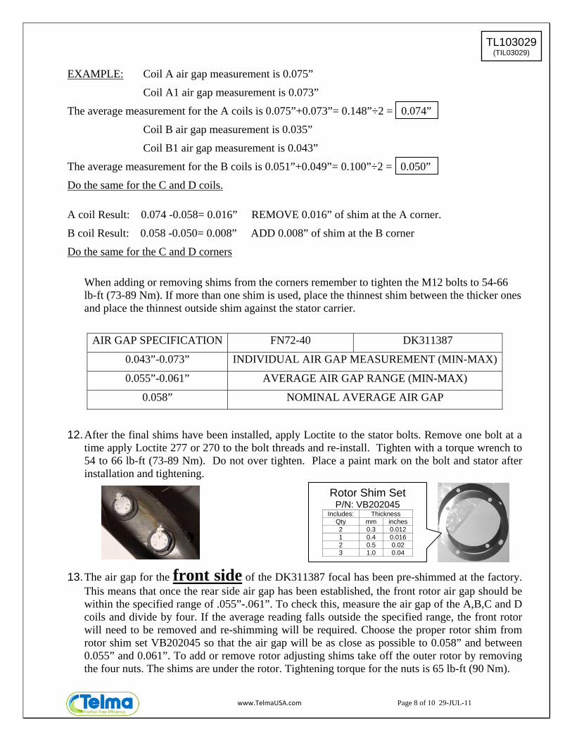
13. The air gap for the front side of the DK311387 focal has been pre-shimmed at the factory. This means that once the rear side air gap has been established, the front rotor air gap should be within the specified range of .055”-.061”. To check this, measure the air gap of the A,B,C and D coils and divide by four. If the average reading falls outside the specified range, the front rotor will need to be removed and re-shimming will be required. Choose the proper rotor shim from rotor shim set VB202045 so that the air gap will be as close as possible to 0.058” and between 0.055” and 0.061”. To add or remove rotor adjusting shims take off the outer rotor by removing the four nuts. The shims are under the rotor. Tightening torque for the nuts is 65 lb-ft (90 Nm).
Rotor Shim Set P/N: VB202045
Includes: Thickness Qty mm inches 2 0.3 0.012 1 0.4 0.016 2 0.5 0.02 3 1.0 0.04

www.TelmaUSA.com Page 9 of 10 29-JUL-11
TL103029(TIL03029)
14. After the Telma air gap has been adjusted, the next step is to install the flange yoke.
15. Reinstall the drive shaft. Always use new straps and bolts to attach the u-joint to the yoke to
avoid reduced clamp load and spinning of the u-joint bearing cap in the yoke.
Telma P/N: TIF04083
Telma P/N: TIF04045
Telma P/N: TIF04046
Telma P/N: TIF04030

www.TelmaUSA.com Page 10 of 10 29-JUL-11
TL103029(TIL03029)
APPENDIX (6 pages following)

5 Assembly and Installation
63Meritor Maintenance Manual 5L (Revised 11-06)
Installation
Input Shaft Assembly
NOTE: The shim pack under the input bearing cage is installed after the end play of the input bearing is inspected and adjusted.
1. Place the differential carrier into a repair stand so that the ring gear is facing DOWN.
2. If necessary, place the clutch collar into the differential carrier so that the teeth on the outside of the collar are toward the input yoke. Install the clutch collar onto the shift fork so the tabs of the fork fit into the slot of the clutch collar.
3. Install the rear side gear and bearing assembly through the clutch collar and into the differential carrier. Figure 5.78.
Figure 5.78
4. Verify that the painted alignment marks on the teeth of the helical gears are visible during the installation of the input shaft assembly. Figure 5.79.
Figure 5.79
5. Install the input shaft assembly into the differential carrier.
A. Connect a lifting device to the input yoke. Lift the input shaft assembly over the bore in the differential carrier.
B. Lubricate the O-rings with axle oil.
C. On 160 Series carriers, rotate the inter-axle differential case so that one of the notches on the case is aligned with the helical driven gear in the carrier. Figure 5.80.
D. Lower the input shaft assembly into the differential carrier. Figure 5.81.
Figure 5.80
Figure 5.81
Figure 5.78
Figure 5.79
REAR SIDEGEAR
1002818b
MATCHMARKS
1002819e
Figure 5.80
Figure 5.81
INTER-AXLEDIFFERENTIAL
CASE HELICALDRIVENGEAR
1002820b
Notches on case mustbe aligned over helical
driven gear.
1002821b

5 Assembly and Installation
64 Meritor Maintenance Manual 5L (Revised 11-06)
Inspection
Adjust the Input Bearing End Play1. Install the capscrews, but not the washers, that fasten the
input bearing cage to the carrier. Rotate the input shaft in each direction to verify that the bearings are correctly installed while you hand-tighten the capscrews. Do not tighten the capscrews.
2. Use a feeler gauge to measure the gap between the input bearing cage and the differential carrier. Inspect the gap at four equally-spaced places on the cage. Figure 5.82.
Figure 5.82
3. Add up the four measurements and determine the average gap between the cage and the carrier. Add 0.005-inch (0.130 mm) to the average gap measurement to determine the size of the shim pack between the cage and the carrier. Figure 5.83.
Figure 5.83
4. Build a shim pack. Use at least three shims when you build a shim pack. Always place the thickest shims in the middle of the shim pack.
5. Remove the capscrews that fasten the input bearing cage to the carrier.
6. Install the shim pack.
A. Connect a lifting device to the input yoke. Lift the input shaft assembly until there is 0.25-0.50-inch (6-12 mm) between the cage and carrier mounting surface.
B. Install the shim pack under the bearing cage. Verify that the hole pattern of the shim pack matches the hole pattern of the cage. Figure 5.84.
C. Install the capscrews and washers that fasten the cage to the carrier. Verify that the capscrews are aligned with the holes in the shim pack. Tighten the capscrews so that the threads engage in the holes of the carrier.
D. Lower the input shaft assembly so that the cage and the shim pack are installed against the carrier. Remove the lifting device from the yoke or flange.
E. Tighten the capscrews to 75-95 lb-ft (100-127 N�m) while rotating the input shaft in each direction to verify that the bearings are correctly installed. @
Figure 5.84
7. Apply Loctite® 277 threadlocker to the input shaft threads of all forward carriers prior to installation of the nut. Begin at the top of the threaded area and allow the Loctite® threadlocker to run down the length of the threaded area.
8. Place a holding tool onto the input yoke or flange and tighten the nut to the specified torque. Refer to Section 8.
9. Rotate the yoke at least one full turn after you tighten the yoke nut to the correct torque specification to ensure that the seal seats correctly.
Figure 5.82
Figure 5.83
1002574c
INPUTBEARINGCAGE
SHIM PACKCONTROLS ENDPLAY OF INPUT BEARING
1002822b
Figure 5.84
SHIMS1002575c

5 Assembly and Installation
68 Meritor Maintenance Manual 5L (Revised 11-06)
CAUTIONInspect the axle breather for contaminants, such as dirt, lubrication or debris, which can cause pressure to build inside the axle. Damage to the seal and premature seal lip wear can result. Remove the axle breather. Use a safe cleaning solvent to clean the inside and outside of the breather.
3. Inspect the axle breather for contaminants, such as dirt, lubrication or debris.
� If you find contaminants in the axle breather: Remove the axle breather. Use a safe cleaning solvent to clean the inside and outside of the breather.
4. Remove the replacement unitized seal from the package. Figure 5.94.
Figure 5.94
CAUTIONIf a yoke is removed after it has been partially or fully installed, the unitized pinion seal will be damaged. Remove and discard the original unitized pinion seal and replace it with a new one.
If a yoke has been installed into the unitized pinion seal and then removed, the inner sleeve of the seal will be damaged. Install a new seal.
5. Select the correct seal driver from Table K. Each seal driver is designed to correctly install a specific diameter seal. To determine the yoke seal diameter, measure the yoke journal. To obtain the Meritor seal driver KIT 4454, refer to the Service Notes page on the front inside cover of this manual.
Table K: Unitized Pinion Seals and Seal Drivers*
Figure 5.94
4005523a
Single Models Tandem Models Axle Model and PositionSeal Service Part Number
Previous Seal Part Number
Seal Drivers Sleeve Drivers
MX-21-160MX-23-160RRF-16-145RF-21-160RF-22-166RF-23-185RS-17-145RS-19-145RS-21-145RS-21-160RS-23-160 /ARS-23-161 /ARS-25-160 /ARS-23-186RS-26-185RS-30-185
RT-34-144 /PRT-34-145 /PMT-40-143RT-40-145 /A /PRT-40-149 /A /PRT-44-145 /PRT-40-160 /A /PRT-40-169 /A /PRT-46-160 /A /PRT-46-169 /A /PRT-46-164EH /PRT-46-16HEH /PRT-50-160 /PRT-52-185*RT-58-185*
14X/16X/18X/38X Forward-Rear Unit Input (FUI)
A1-1205X2728 A-1205R2592 2728T1 2728T2
14X/16X Forward-Rear Unit Output (FUO)
A1-1205Y2729 A-1205P2590 2729T1 2729T2
14X Rear-Rear Unit Input (RUI)
A1-1205Z2730 A-1205N2588 2730T1 Not Required — Sleeve is unitized
16X/18X Rear-Rear Unit Input (RUI)
A1-1205A2731 A-1205Q2591 2731T1 Not Required — Sleeve is unitized
* Forward and rear input only.
Forward input and output seals must be serviced with the seal and sleeve. The service part number provides both when required.

5 Assembly and Installation
69Meritor Maintenance Manual 5L (Revised 11-06)
6. Position the driver and seal. Figure 5.95.
� If you use the R4422401 driver tool to install a forward tandem axle seal: The driver tool outer spokes or fins must fit between the bearing cage bolts. Ensure that the bolts on the bottom of the bearing cage are not in the path of the driver spokes.
� If the driver spokes contact the bearing cage bolts: The driver will incorrectly install the seal into the bearing cage seat and can also result in damage to the driver. The reference mark on the driver tool must be in the 12 o’clock or the 6 o’clock positions when you install the new seal.
Figure 5.95
CAUTIONUse a rubber mallet to install the seal. Do not use a steel, brass or plastic hammer. Using a steel, brass or plastic hammer can damage the seal and driver tool.
7. Use a rubber mallet to drive the seal into or against the bearing cage. The seal must fully seat into or against the bearing cage. Figure 5.96.
8. Visually inspect the seal to verify that it is seated correctly.
Figure 5.96
Installing a Multiple-Lip Seal (MLS)140, 160 and 180 Series Single Drive Axles140, 160, 180 and 380 Series Tandem Drive Axles
Meritor multiple-lip seals feature a separable sleeve installed onto the yokes at the tandem forward-rear input and forward-rear output positions. No sleeve is used on the rear-rear input.
Installation of the new seals requires a set of four seal drivers and two sleeve drivers. Refer to Table L for part numbers.
Table L: Multiple-Lip Seal (MLS) Seal Drivers and Sleeves Part Numbers
Figure 5.95
Position the sealdriver to prevent the
driver spokes fromhitting the fastener
heads on theforward tandem
output seals.
SEALDRIVER
FASTENERHEADS
SEAL DRIVERR4422401
1003388c
Figure 5.96
The seal mustbe fully seatedin or againstthe bearing cage.
REFERENCEMARK
SEALDRIVER
R4422401
RUBBERMALLET
1003389d
Axle Model and PositionSeal ServicePart Number
Previous Seal Part Number Seal Drivers Sleeve Drivers
140, 160, 180 and 380 Forward-Rear Unit Input (FUI)
A1-1205X2728 A-1205R2592 2728T1 2728T2
140 and 160 Forward-Rear Unit Output (FUO) A1-1205Y2729 A-1205P2590 2729T1 2729T2
140 Rear-Rear Unit Input (RUI) A1-1205Z2730 A-1205N2588 2730T1 Not Required — Sleeve is unitized
160 and 180 Rear-Rear Unit Input (RUI) A1-1205A2731 A-1205Q2591 2731T1 Not Required — Sleeve is unitized

5 Assembly and Installation
70 Meritor Maintenance Manual 5L (Revised 11-06)
Special Tools for Installing Multiple-Lip Seals (MLS)
Forward input and output seals must be serviced with the seal and sleeve. The service part number provides both when required.Check your application carefully before installing the multiple-lip seal.
There are six new installation drivers required for replacement of the multiple-lip axle yoke seals. Figure 5.97. To obtain these sleeves, seals and drivers, call ArvinMeritor’s Commercial Vehicle Aftermarket at 888-725-9355.
� A sleeve driver and seal driver for the forward-rear input
� A sleeve driver and seal driver for the forward-rear output
� Two model specific seal drivers for the rear-rear input
Figure 5.97
WARNINGSolvent cleaners can be flammable, poisonous and cause burns. Examples of solvent cleaners are carbon tetrachloride, and emulsion-type and petroleum-base cleaners. Read the manufacturer’s instructions before using a solvent cleaner, then carefully follow the instructions. Also follow the procedures below.
� Wear safe eye protection.
� Wear clothing that protects your skin.
� Work in a well-ventilated area.
� Do not use gasoline, or solvents that contain gasoline. Gasoline can explode.
� You must use hot solution tanks or alkaline solutions correctly. Read the manufacturer’s instructions before using hot solution tanks and alkaline solutions. Then carefully follow the instructions.
1. Clean the ground and polished surface of the yoke journal using a clean shop towel and a safe cleaning solvent. Do not use abrasive cleaners, towels or scrubbers to clean the yoke or flange surface. Do not use gasoline.
2. Inspect the yoke seal area for damage that could cause lubricant leaks after you install the seal. Use emery paper or an equivalent product to remove scratches, nicks or burrs only.
3. Install the deflector, if equipped, onto the yoke. You must install the deflector before you install the sleeve into the yoke. Figure 5.98.
Figure 5.98
WARNINGObserve all warnings and cautions provided by the press manufacturer to avoid damage to components and serious personal injury.
Do not hit steel parts with a steel hammer. Pieces of a part can break off. Serious personal injury and damage to components can result.
4. Apply a light coat of axle oil to the yoke seal journal. Position the sleeve into the forward-rear axle output yoke sleeve driver. Do not touch the greased areas of the sleeve. The sleeve must be kept clean prior to assembly into the seal. Use an arbor press and the appropriate driver to install the sleeve into the yoke. Verify that the sleeve is fully-seated in the yoke to prevent damage to components. Figure 5.99.
The yoke must be fully pressed into the sleeve driver until the end of the yoke bottoms out in the sleeve driver. This will correctly position the sleeve on the yoke. When correctly seated, the forward-rear output sleeve is positioned 0.200-inch ± 0.030-inch (5 mm ± 0.75 mm) from the end of the yoke. Figure 5.100.
� If you do not have a press: Position the yoke on a five-inch (127 mm) spacer on a workbench. Use a dead-blow hammer and the appropriate driver to install the sleeve into the yoke. Figure 5.101.
Figure 5.97
4005371a
2729T1 2730T1
2731T12729T2
2728T1
2728T2
Figure 5.98
4004889a
YOKE
DEFLECTOR,IF EQUIPPED
SLEEVE
DRIVER

8 Specifications
99Meritor Maintenance Manual 5L (Revised 11-06)
Table T: Tandem Axles
Table U: Tridem Axles
Axle Model
Pinion Nut Location RT-140 RT-145, RT-149
RT-160, RT-164, RT-169 RT-185
RT-380 With IAD
RT-380Without IAD
First Carrier Input Yoke
Fastener Size
750-850 lb-ft (1020-1150 N�m)
M45 X 1.5
750-850 lb-ft (1020-1150 N�m)
M45 X 1.5
750-850 lb-ft (1020-1150 N�m)
M45 X 1.5
750-850 lb-ft (1020-1150 N�m)
1-3/4 - 12 UN
750-850 lb-ft (1020-1150 N�m)
1-3/4 - 12 UN
900-1200 lb-ft (1224-1632 N�m)
1-3/4 - 12 UN
First Carrier Output Yoke
Fastener Size
600-700 lb-ft (815-950 N�m)
M32 X 1.5
600-700 lb-ft (815-950 N�m)
M39 X 1.5
600-700 lb-ft (815-950 N�m)
M39 X 1.5
600-700 lb-ft (815-950 N�m)
1-1/2 - 12 UNF
600-700 lb-ft (815-950 N�m)
1-1/2 - 12 UNF
600-700 lb-ft (815-950 N�m)
1-1/2 - 12 UNF
Second Carrier Input Yoke
Fastener Size
740-920 lb-ft (1000-1245 N�m)
M32 X 1.5
920-1130 lb-ft (1250-1535 N�m)
M39 X 1.5
1000-1230 lb-ft (1350-1670 N�m)
M45 X 1.5
1000-1230 lb-ft (1350-1670 N�m)
M45 X 1.5
800-1100 lb-ft (1085-1496 N�m)
1-1/2 - 12 UNF
800-1100 lb-ft (1085-1496 N�m)
1-1/2 - 12 UNF
Axle Model
Pinion Nut Location RZ-164 RZ-166 RZ-186 RZ-188
First Carrier Input Yoke
Fastener Size
600-800 lb-ft (815-1085 N�m)
M45 X 1.5
600-800 lb-ft (815-1085 N�m)
M45 X 1.5
600-800 lb-ft (815-1085 N�m)
1-3/4 - 12 UN
600-800 lb-ft (815-1085 N�m)
1-3/4 - 12 UN
First Carrier Output Yoke
Fastener Size
450-650 lb-ft (610-880 N�m)
M39 X 1.5
450-650 lb-ft (610-880 N�m)
M39 X 1.5
450-650 lb-ft (610-880 N�m)
1-1/2 -12 UNF
450-650 lb-ft (610-880 N�m)
1-1/2 - 12 UNF
Second Carrier Input Yoke
Fastener Size
600-800 lb-ft (815-1085 N�m)
M45 X 1.5
600-800 lb-ft (815-1085 N�m)
M45 X 1.5
600-800 lb-ft (815-1085 N�m)
M45 X 1.5
600-800 lb-ft (815-1085 N�m)
1-3/4 - 12 UN
Second Carrier Output Yoke
Fastener Size
450-650 lb-ft (610-880 N�m)
M39 X 1.5
450-650 lb-ft (610-880 N�m)
M39 X 1.5
450-650 lb-ft (610-880 N�m)
M39 X 1.5
450-650 lb-ft (610-880 N�m)
1-1/2 - 12 UNF
Third Carrier Input Yoke
Fastener Size
920-1130 lb-ft (1250-1535 N�m)
M39 X 1.5
1000-1230 lb-ft (1350-1670 N�m)
M45 X 1.5
1000-1230 lb-ft (1350-1670 N�m)
M45 X 1.5
1000-1230 lb-ft (1350-1670 N�m)
M45 X 1.5