telma parts
DESCRIPTION
Telma Retarder Part ListTRANSCRIPT
SPARE PARTS CATALOGUE
AC – SERIES AXIAL RETARDER
INSULATED EARTH RETURN
OC443013/aEdition 06/2001
TABLE OF CONTENTS
Technical specifications of the AC series retarders ................................................................ 2
Identification of the retarders by their dimensions (mm) ........................................................ 3
Indexes, designation and dimensions for identification of the coupling flanges............... 4-5
Stator assembly................................................................................................................ ........ 6-8
Coil assembly .................................................................................................................. ............ 9
Retarder shaft assembly ...................................................................................................... 10 -12
SAE coupling flanges with metric fasteners...................................................................... 13-14
SAE coupling flanges with anglo-american ............................................................................ 15
70° cross–serrated coupling flanges and SCANIA yokes ..................................................... 16
DIN flat coupling flanges ..................................................................................................... 1 7-18
12 V and 24 V wiring diagrams – Insulated earth return ................................................... 19-22
Junction block assembly – VD 407 390 ................................................................................... 23
Connecting block and earth terminal – VD 408 573 ............................................................... 24
Greasing ....................................................................................................................... .............. 25
Crimping tool .................................................................................................................. ........... 25
Wiring repair kit .............................................................................................................. ........... 25
Protection of terminals against corrosion .............................................................................. 25
Replacement of a coil .......................................................................................................... ..... 26
– 1 –
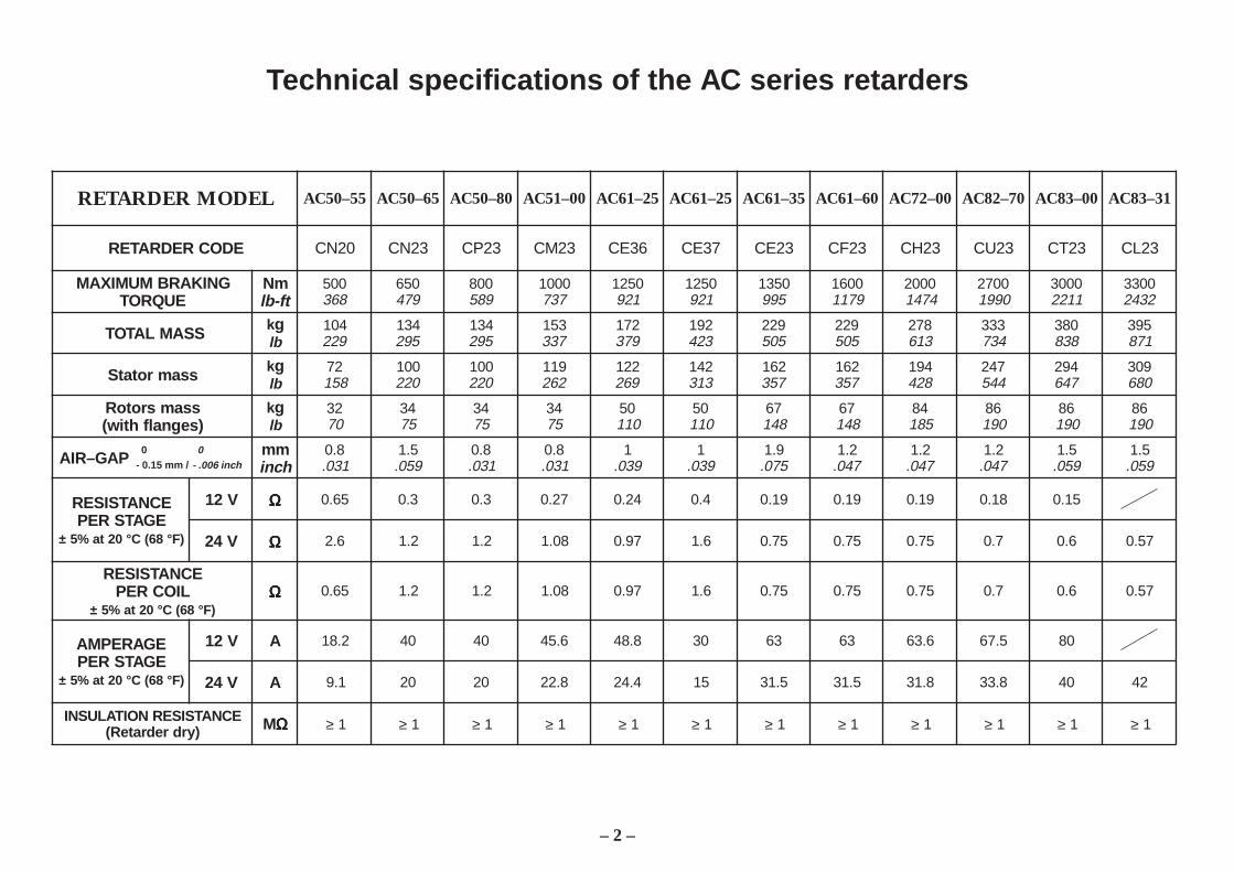
Technical specifications of the AC series retarders
– 2 –
LEDOMREDRATER 55–05CA 56–05CA 08–05CA 00–15CA 52–16CA 52–16CA 53–16CA 06–16CA 00–27CA 07–28CA 00–38CA 13–38CA
EDOCREDRATER 02NC 32NC 32PC 32MC 63EC 73EC 32EC 32FC 32HC 32UC 32TC 32LC
GNIKARBMUMIXAMEUQROT
mNtf-bl
005863
056974
008985
0001737
0521129
0521129
0531599
00619711
00024741
00720991
00031122
00332342
SSAMLATOT kgbl
401922
431592
431592
351733
271973
291324
922505
922505
872316
333437
083838
593178
ssamrotatS kgbl
27851
001022
001022
911262
221962
241313
261753
261753
491824
742445
492746
903086
ssamsrotoR)segnalfhtiw(
kgbl
2307
4357
4357
4357
05011
05011
76841
76841
48581
68091
68091
68091
PAG–RIA mmhcni
8.0130.
5.1950.
8.0130.
8.0130.
1930.
1930.
9.1570.
2.1740.
2.1740.
2.1740.
5.1950.
5.1950.
ECNATSISEREGATSREP
F°86(C°02ta%5± )
V21 ΩΩΩΩΩ 56.0 3.0 3.0 72.0 42.0 4.0 91.0 91.0 91.0 81.0 51.0
V42 ΩΩΩΩΩ 6.2 2.1 2.1 80.1 79.0 6.1 57.0 57.0 57.0 7.0 6.0 75.0
ECNATSISERLIOCREP
F°86(C°02ta%5± )ΩΩΩΩΩ 56.0 2.1 2.1 80.1 79.0 6.1 57.0 57.0 57.0 7.0 6.0 75.0
EGAREPMAEGATSREP
)F°86(C°02ta%5±
V21 A 2.81 04 04 6.54 8.84 03 36 36 6.36 5.76 08
V42 A 1.9 02 02 8.22 4.42 51 5.13 5.13 8.13 8.33 04 24
ECNATSISERNOITALUSNI)yrdredrateR( MΩΩΩΩΩ ≥ 1 ≥ 1 ≥ 1 ≥ 1 ≥ 1 ≥ 1 ≥ 1 ≥ 1 ≥ 1 ≥ 1 ≥ 1 ≥ 1
0- 0.15 mm /
0- .006 inch
noisnemiDREDRATER
55–05CA....02NC
56–05CA....32NC
08–05CA....32PC
00–15CA....32MC
52–16CA....63EC
52–16CA....73EC
53–16CA....32EC
06–16CA....32FC
00–27CA....32HC
07–28CA....32UC
00–38CA....32TC
13–38CA....32LC
A 363 363 363 363 074 074 074 074 594 035 035 035
B 383 383 383 383 694 694 694 694 915 455 455 455
C 022 123 123 123 662 662 853 853 383 814 814 814
D 421 5.912 5.912 5.912 451 451 022 022 932 2.082 2.082 2.082
E 8.0 5.1 8.0 8.0 1 1 9.1 2.1 2.1 2.1 5.1 5.1
∅F 253 253 253 253 424 424 644 644 084 005 005 005
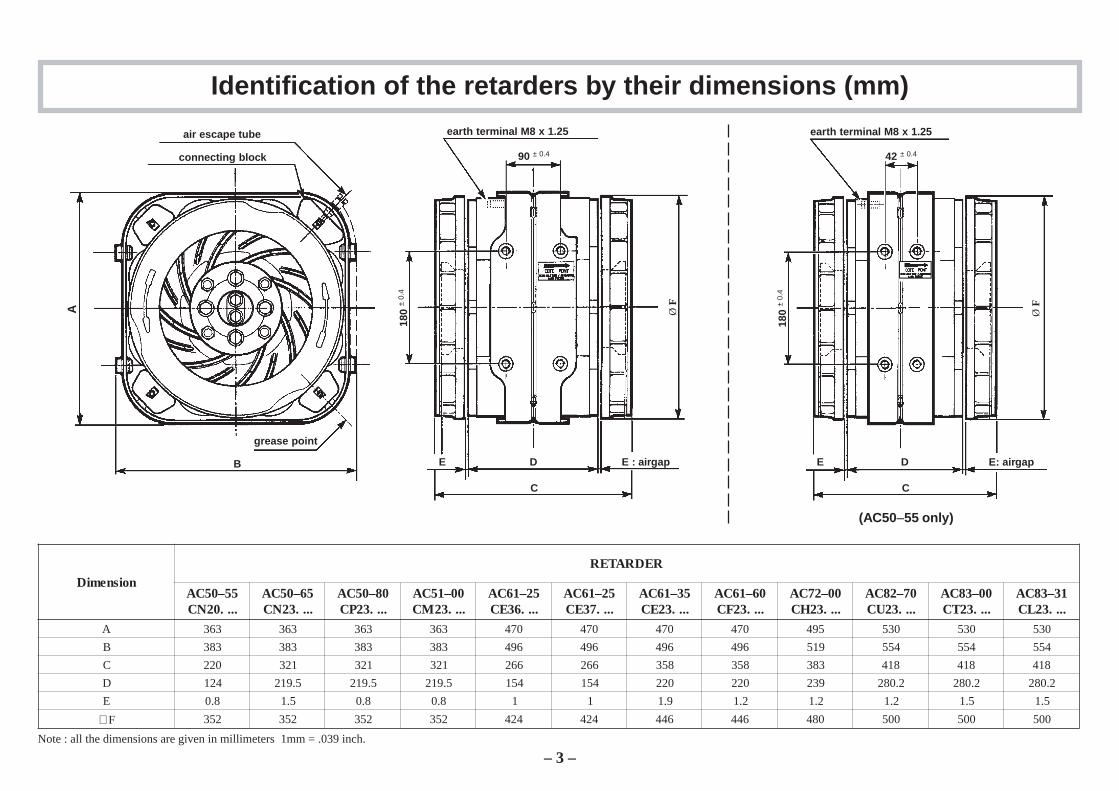
Identification of the retarders by their dimensions (mm)
Note : all the dimensions are given in millimeters 1mm = .039 inch.
– 3 –
air escape tube
connecting block
earth terminal M8 x 1.25
grease point
A Ø F
180
± 0.
4
E : airgap
90 ± 0.4
B DE
C
earth terminal M8 x 1.25
180
± 0.
4
42 ± 0.4
DE
C
(AC50–55 only)
Ø F
E: airgap
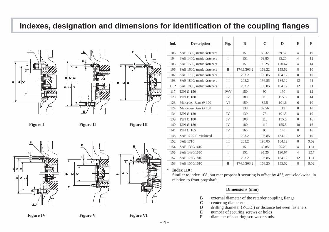
Figure I Figure II Figure III
Figure IV Figure V
Indexes, designation and dimensions for identification of the coupling flanges
.dnI noitpircseD .giF B C D E F
301 srenetsafcirtem,0031EAS I 151 23.06 73.97 4 01
401 srenetsafcirtem,0041EAS I 151 58.96 52.59 4 21
501 srenetsafcirtem,0051EAS I 151 52.59 76.021 4 41
601 srenetsafcirtem,0061EAS II 2.302/6.471 22.861 25.551 8 01
701 srenetsafcirtem,0071EAS III 2.302 58.691 21.481 8 01
801 srenetsafcirtem,0081EAS III 2.302 58.691 21.481 21 11
*011 srenetsafcirtem,0081EAS III 2.302 58.691 21.481 21 11
711 051ØNID V/VI 051 09 031 8 21
021 081ØNID VI 081 011 5.551 8 41
321 021ØzneB-sedecreM IV 051 5.28 6.101 6 01
421 031ØzneB-sedecreM I 031 65.28 211 8 01
431 021ØNID VI 031 57 5.101 8 01
931 081ØNID VI 081 011 5.551 8 61
041 081ØNID VI 081 011 5.551 01 61
141 561ØNID VI 561 59 041 8 61
541 decrofnierR0071EAS III 2.302 58.691 21.481 21 01
251 0171EAS III 2.302 58.691 21.481 8 25.9
451 0141/0531EAS I 151 58.96 52.59 4 1.11
551 0551/0841EAS I 151 52.59 76.021 4 7.21
751 0181/0671EAS III 2.302 58.691 21.481 21 1.11
851 0161/0551EAS II 2.302/6.471 52.861 25.551 8 25.9
* Index 110 :Similar to index 108, but rear propshaft securing is offset by 45°, anti-clockwise, inrelation to front propshaft.
Dimensions (mm)
B external diameter of the retarder coupling flangeC centering diameterD drilling diameter (P.C.D.) or distance between fastenersE number of securing screws or holesF diameter of securing screws or studsFigure VI
– 4 –

Figure VII Figure VIII
Indexes, designation and dimensions for identification of the coupling flanges
Figure IX
.dnI noitpircseD .giF B C D E F
821 021Ønoitarres–ssorC IIV )00-15CAot56-05CA(051)06-16CA/53-16CA(561 001 4 01
921 051Ønoitarres–ssorC IIV)00-15CAot56-05CA(051)06-16CAot52-16CA(561)00-38CAot00-27CA(081
031 4 21
531 561ØleseidnassiN IIIV 561 09 611x08 4 61
631 004P/04PAINACS XI 58x9.131 4 21
731 005P/05PAINACS XI 59x7.521 4 21
831 081Ønoitarres–ssorC IIV 081 051 4 41
Dimensions (mm)
B external diameter of the retarder coupling flangeC centering diameterD drilling diameter (P.C.D.) or distance between fastenersE number of securing screws or holesF diameter of securing screws or studs
– 5 –
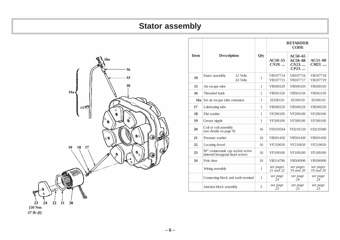
Stator assembly
metI noitpircseD ytQ
REDRATEREDOC
55–05CA....02NC
56–05CA08–05CA....32NC....32PC
00–15CA.....32MC
01stloV21ylbmessarotatSstloV42
1417701BV517701BV
617701BV717701BV
817701BV917701BV
51 ebutepacseriA 1 023005BV 023005BV 023005BV
61 hsubdedaerhT 1 051105BV 051105BV 051105BV
a61 noisnetxeebutepacseriateS 1 011001ZJ 011001ZJ 011001ZJ
71 ebutgnitacirbuL 1 022005BV 022005BV 022005BV
81 rehsawtalF 1 001002FV 001002FV 001002FV
91 elppinesaerG 1 001005FV 001005FV 001005FV
02 ylbmessaliocrolioC)9egapnosliatedees( 61 495013DV 021012DV 083012DV
12 rehsawerusserP 61 034105BV 034105BV 034105BV
22 lewodgnitacoL 61 056012FV 056012FV 056012FV
32 wercstekcospacknusretnuoc°09)wercsdaehlanogaxehlanretni( 61 001901FV 001901FV 001901FV
42 eohseloP 61 687415BV 099605BV 099605BV
ylbmessagniriW 1 segapees22dna12
segapees02dna91
segapees02dna91
lanimrethtraednakcolbgnitcennoC 1 egapees42
egapees42
egapees42
ylbmessakcolbnoitcnuJ 3 egapees32
egapees32
egapees32
– 6 –
(50 Nm37 lb–ft)
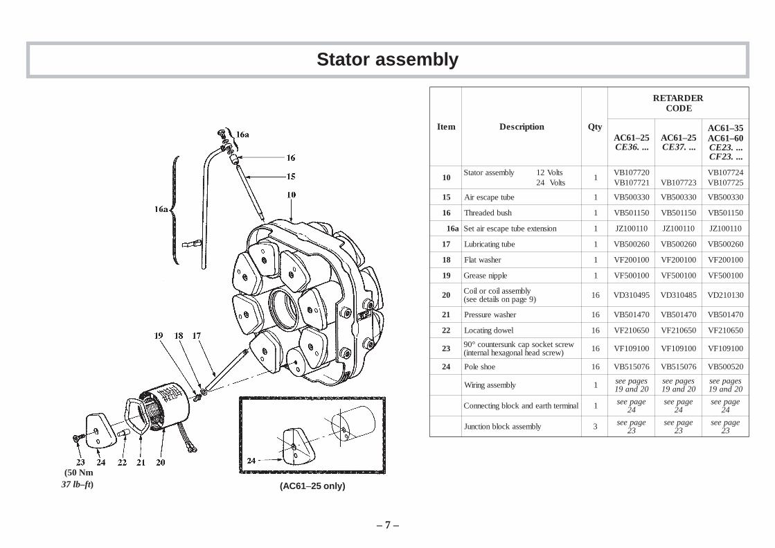
Stator assembly
metI noitpircseD ytQ
REDRATEREDOC
52–16CA....63EC
52–16CA....73EC
53–16CA06–16CA....32EC....32FC
01stloV21ylbmessarotatSstloV42
1027701BV127701BV 327701BV
427701BV527701BV
51 ebutepacseriA 1 033005BV 033005BV 033005BV
61 hsubdedaerhT 1 051105BV 051105BV 051105BV
a61 noisnetxeebutepacseriateS 1 011001ZJ 011001ZJ 011001ZJ
71 ebutgnitacirbuL 1 062005BV 062005BV 062005BV
81 rehsawtalF 1 001002FV 001002FV 001002FV
91 elppinesaerG 1 001005FV 001005FV 001005FV
02 ylbmessaliocrolioC)9egapnosliatedees( 61 594013DV 584013DV 031012DV
12 rehsawerusserP 61 074105BV 074105BV 074105BV
22 lewodgnitacoL 61 056012FV 056012FV 056012FV
32 wercstekcospacknusretnuoc°09)wercsdaehlanogaxehlanretni( 61 001901FV 001901FV 001901FV
42 eohseloP 61 670515BV 670515BV 025005BV
ylbmessagniriW 1 segapees02dna91
segapees02dna91
segapees02dna91
lanimrethtraednakcolbgnitcennoC 1 egapees42
egapees42
egapees42
ylbmessakcolbnoitcnuJ 3 egapees32
egapees32
egapees32
(AC61–25 only)
– 7 –
(50 Nm37 lb–ft)
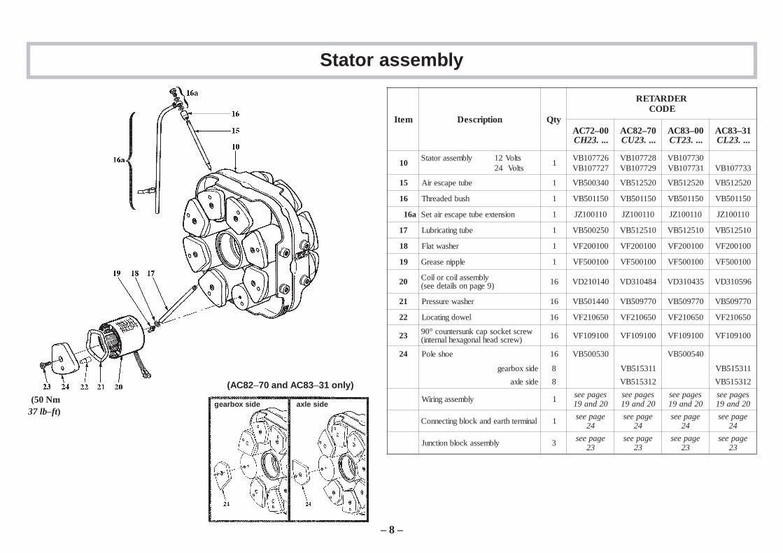
Stator assembly
metI noitpircseD ytQ
REDRATEREDOC
00–27CA....32HC
07–28CA....32UC
00–38CA....32TC
13–38CA....32LC
01stloV21ylbmessarotatSstloV42
1627701BV727701BV
827701BV927701BV
037701BV137701BV 337701BV
51 ebutepacseriA 1 043005BV 025215BV 025215BV 025215BV
61 hsubdedaerhT 1 051105BV 051105BV 051105BV 051105BV
a61 noisnetxeebutepacseriateS 1 011001ZJ 011001ZJ 011001ZJ 011001ZJ
71 ebutgnitacirbuL 1 052005BV 015215BV 015215BV 015215BV
81 rehsawtalF 1 001002FV 001002FV 001002FV 001002FV
91 elppinesaerG 1 001005FV 001005FV 001005FV 001005FV
02 ylbmessaliocrolioC)9egapnosliatedees( 61 041012DV 484013DV 534013DV 695013DV
12 rehsawerusserP 61 044105BV 077905BV 077905BV 077905BV
22 lewodgnitacoL 61 056012FV 056012FV 056012FV 056012FV
32 wercstekcospacknusretnuoc°09)wercsdaehlanogaxehlanretni( 61 001901FV 001901FV 001901FV 001901FV
42 eohseloP 61 035005BV 045005BV
edisxobraeg 8 113515BV 113515BV
ediselxa 8 213515BV 213515BV
ylbmessagniriW 1 segapees02dna91
segapees02dna91
segapees02dna91
segapees02dna91
lanimrethtraednakcolbgnitcennoC 1 egapees42
egapees42
egapees42
egapees42
ylbmessakcolbnoitcnuJ 3 egapees32
egapees32
egapees32
egapees32
– 8 –
(AC82–70 and AC83 –31 only)
gearbox side axle side (50 Nm37 lb–ft)
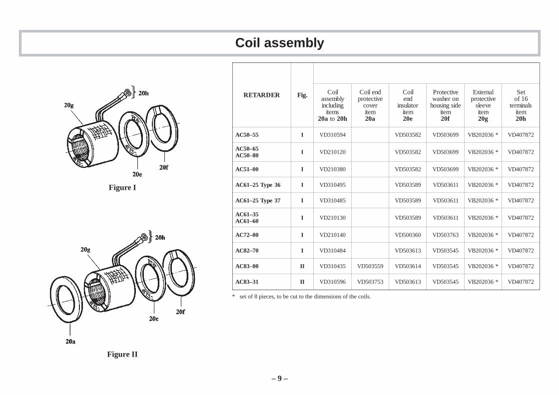
Coil assembly
Figure I
Figure II
REDRATER .giF lioCylbmessagnidulcni
smetia02 ot h02
dnelioCevitcetorp
revocmetia02
lioCdne
rotalusnimetie02
evitcetorPnorehsawedisgnisuoh
metif02
lanretxEevitcetorp
eveelsmetig02
teS61fo
slanimretmetih02
55–05CA I 495013DV 285305DV 996305DV *630202BV 278704DV
56–05CA08–05CA I 021012DV 285305DV 996305DV *630202BV 278704DV
00–15CA I 083012DV 285305DV 996305DV *630202BV 278704DV
63epyT52–16CA I 594013DV 985305DV 116305DV *630202BV 278704DV
73epyT52–16CA I 584013DV 985305DV 116305DV *630202BV 278704DV
53–16CA06–16CA I 031012DV 985305DV 116305DV *630202BV 278704DV
00–27CA I 041012DV 063005DV 367305DV *630202BV 278704DV
07–28CA I 484013DV 316305DV 545305DV *630202BV 278704DV
00–38CA II 534013DV 955305DV 416305DV 545305DV *630202BV 278704DV
13–38CA II 695013DV 357305DV 316305DV 545305DV *630202BV 278704DV
* set of 8 pieces, to be cut to the dimensions of the coils.
– 9 –
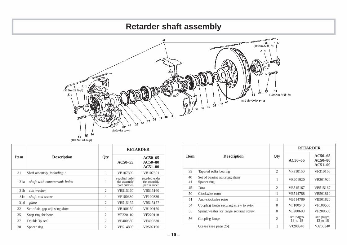
Retarder shaft assembly
metI noitpircseD ytQ
REDRATER
55–05CA56–05CA08–05CA00–15CA
13 ,ylbmessatfahS :gnidulcni 1 003701BV 103701BV
a13 selohknusretnuochtiwtfahs 1rednudeilppus
ylbmessaehtrebmuntrap
rednudeilppusylbmessaehtrebmuntrap
b13 rehsawbat 2 061515BV 061515BV
c13 wercsdnetfahs 4 083001FV 083001FV
d13 etalp 2 751515BV 751515BV
23 smihsgnitsujdapag–riafoteS 1 051001BV 051001BV
53 erobrofgnirpanS 2 011022FV 011022FV
73 laespilelbuoD 2 033004FV 033004FV
83 gnirrecapS 2 808415BV 001705BV
metI noitpircseD ytQ
REDRATER
55–05CA56–05CA08–05CA00–15CA
93 gniraebrellorderepaT 2 051013FV 051013FV
0414
smihsgnitsujdagniraebfoteSgnirrecapS
1 029102BV 029102BV
54 tsuD 2 761515BV 761515BV
05 rotoresiwkcolC 1 887415BV 018105BV
15 rotoresiwkcolc–itnA 1 987415BV 028105BV
45 rotorotwercsgnirucesegnalfgnilpuoC 8 045001FV 005001FV
55 wercsgnirucesegnalfrofrehsawgnirpS 8 006002FV 006002FV
65 egnalfgnilpuoC 2 segapees81ot31
segapees81ot31
)52egapees(esaerG 1 043002JV 043002JV
– 10 –
(30 Nm 22 lb–ft)
(100 Nm 74 lb–ft)
(100 Nm 74 lb–ft)
(30 Nm 22 lb–ft)
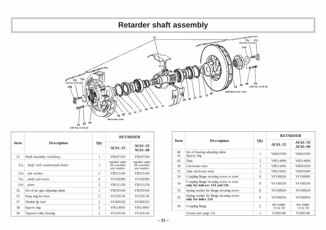
Retarder shaft assembly
metI noitpircseD ytQ
REDRATER
52–16CA 53–16CA06–16CA
13 ,ylbmessatfahS :gnidulcni 1 303701BV 403701BV
a13 selohknusretnuochtiwtfahs 1rednudeilppus
ylbmessaehtrebmuntrap
rednudeilppusylbmessaehtrebmuntrap
b13 rehsawbat 2 061515BV 061515BV
c13 wercsdnetfahs 4 083001FV 083001FV
d13 etalp 2 851515BV 851515BV
23 smihsgnitsujdapag–riafoteS 1 061001BV 061001BV
53 erobrofgnirpanS 2 031022FV 031022FV
73 laespilelbuoD 2 023004FV 023004FV
83 gnirrecapS 2 199415BV 199415BV
93 gniraebrellorderepaT 2 031013FV 031013FV
metI noitpircseD ytQREDRATER
52–16CA 53–16CA06–16CA
0414
smihsgnitsujdagniraebfoteSgnirrecapS 1 039102BV 039102BV
54 tsuD 2 099415BV 099415BV
05 rotoresiwkcolC 1 140515BV 038105BV
15 rotoresiwkcolc–itnA 1 240515BV 048105BV
45 rotorotwercsgnirucesegnalfgnilpuoC 8 028001FV 008001FV
45 rotorotwercsgnirucesegnalfgnilpuoCrofylno 631dna431sexedni 8 033801FV 033801FV
55 wercsgnirucesegnalfrofrehsawgnirpS 8 028002FV 028002FV
55 wercsgnirucesegnalfrofrehsawgnirpSrofylno 431xedni 8 018002FV 018002FV
65 egnalfgnilpuoC 2 segapees81ot31
segapees81ot31
)52egapees(esaerG 1 043002JV 043002JV
– 11 –
(30 Nm 22 lb–ft)
(180 Nm 132 lb–ft)
(180 Nm 132 lb–ft)
(30 Nm 22 lb–ft)
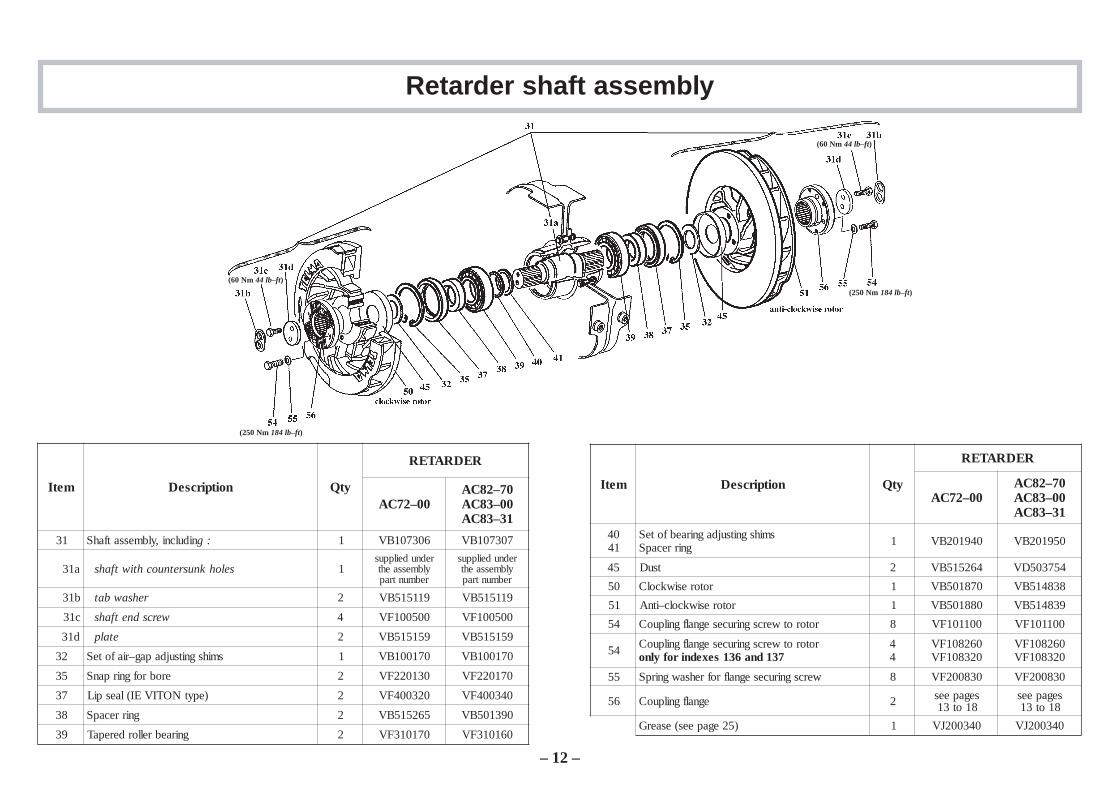
metI noitpircseD ytQ
REDRATER
00–27CA07–28CA00–38CA13–38CA
13 nidulcni,ylbmessatfahS :g 1 603701BV 703701BV
a13 selohknusretnuochtiwtfahs 1rednudeilppus
ylbmessaehtrebmuntrap
rednudeilppusylbmessaehtrebmuntrap
b13 rehsawbat 2 911515BV 911515BV
c13 wercsdnetfahs 4 005001FV 005001FV
d13 etalp 2 951515BV 951515BV
23 smihsgnitsujdapag–riafoteS 1 071001BV 071001BV
53 erobrofgnirpanS 2 031022FV 071022FV
73 )epytNOTIVEI(laespiL 2 023004FV 043004FV
83 gnirrecapS 2 562515BV 093105BV
93 gniraebrellorderepaT 2 071013FV 061013FV
Retarder shaft assembly
metI noitpircseD ytQ
REDRATER
00–27CA07–28CA00–38CA13–38CA
0414
smihsgnitsujdagniraebfoteSgnirrecapS 1 049102BV 059102BV
54 tsuD 2 462515BV 457305DV
05 rotoresiwkcolC 1 078105BV 838415BV
15 rotoresiwkcolc–itnA 1 088105BV 938415BV
45 rotorotwercsgnirucesegnalfgnilpuoC 8 001101FV 001101FV
45 rotorotwercsgnirucesegnalfgnilpuoCrofylno 731dna631sexedni
44
062801FV023801FV
062801FV023801FV
55 wercsgnirucesegnalfrofrehsawgnirpS 8 038002FV 038002FV
65 egnalfgnilpuoC 2 segapees81ot31
segapees81ot31
)52egapees(esaerG 1 043002JV 043002JV
– 12 –
(60 Nm 44 lb–ft)
(250 Nm 184 lb–ft)
(250 Nm 184 lb–ft)
(60 Nm 44 lb–ft)
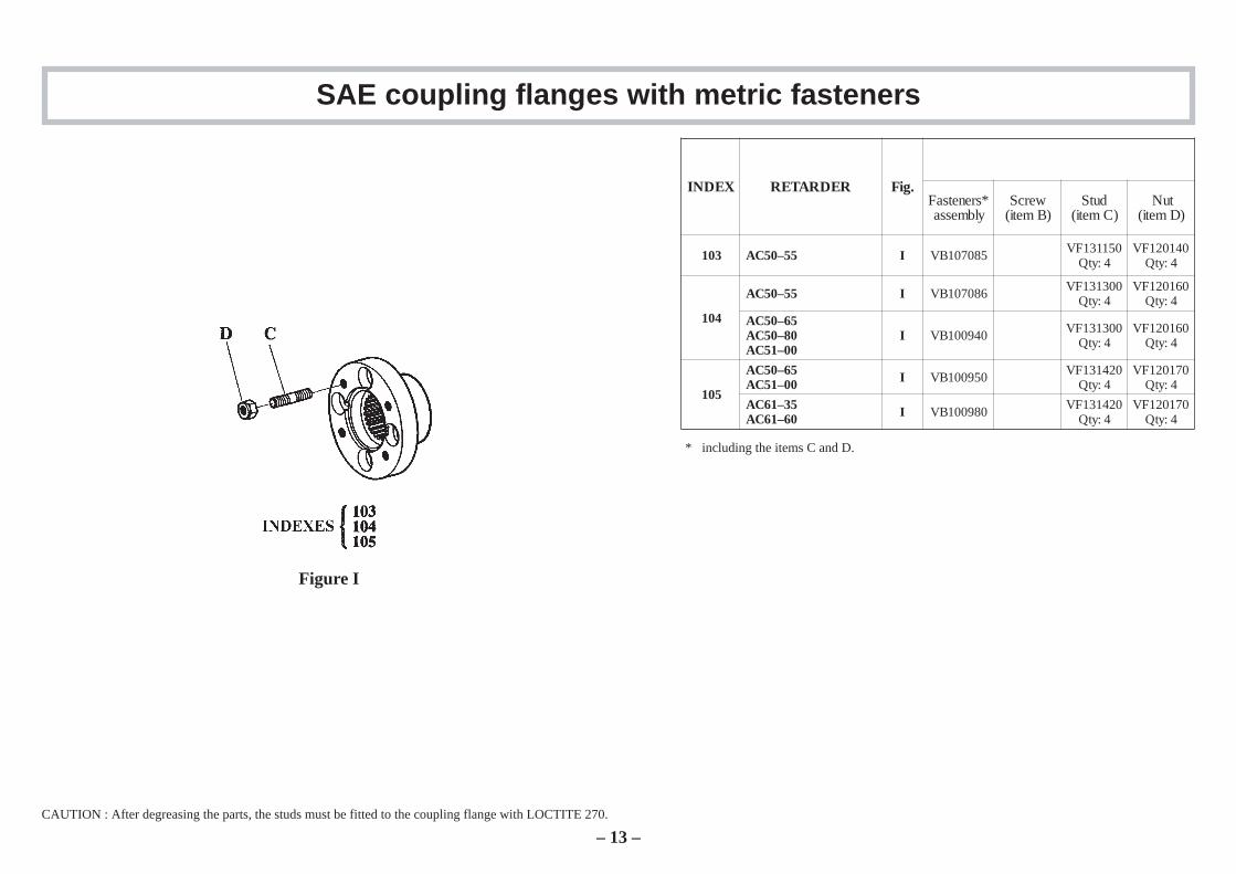
SAE coupling flanges with metric fasteners
XEDNI REDRATER .giF*srenetsaFylbmessa
wercS)Bmeti(
dutS)Cmeti(
tuN)Dmeti(
301 55–05CA I 580701BV 051131FV4:ytQ
041021FV4:ytQ
401
55–05CA I 680701BV 003131FV4:ytQ
061021FV4:ytQ
56–05CA08–05CA00–15CA
I 049001BV 003131FV4:ytQ
061021FV4:ytQ
501
56–05CA00–15CA I 059001BV 024131FV
4:ytQ071021FV
4:ytQ
53–16CA06–16CA I 089001BV 024131FV
4:ytQ071021FV
4:ytQ
CAUTION : After degreasing the parts, the studs must be fitted to the coupling flange with LOCTITE 270.
Figure I
– 13 –
* including the items C and D.

SAE coupling flanges with metric fasteners
xednI REDRATER .giF
ebotderedro
yletarapes
*srenetsaFylbmessa
wercS)Bmeti(
dutS)Cmeti(
tuN)Dmeti(
etalpgniniateR)Gmeti(
601
56–05CA08–05CA00–15CA
II 029201BV 012911FV8:ytQ
041021FV8:ytQ
130515BV1:ytQ
52–16CA VI 991701BV 032911FV8:ytQ
041021FV8:ytQ
030515BV1:ytQ
53–16CA06–16CA VI 091701BV 032911FV
8:ytQ041021FV
8:ytQ130515BV
1:ytQ
00–27CA07–28CA VI 371701BV 001131FV
8:ytQ041021FV
8:ytQ
70106–16CA III 191701BV 032911FV
8:ytQ041021FV
8:ytQ130515BV
8:ytQ
00–27CA III 471701BV 032911FV8:ytQ
041021FV8:ytQ
038205BV1:ytQ
801
52–16CA III 102701BV 021911FV21:ytQ
051021FV21:ytQ
030515BV1:ytQ
53–16CA06–16CA III 291701BV 021911FV
21:ytQ051021FV
21:ytQ130515BV
1:ytQ
00–27CA07–28CA00–38CA13–38CA
III 671701BV 021911FV21:ytQ
051021FV21:ytQ
038205BV1:ytQ
011
00–27CA07–28CA00–38CA13–38CA
III 671701BV 021911FV21:ytQ
051021FV21:ytQ
038205BV1:ytQ
541
53–16CA06–16CA III 391701BV 032911FV
21:ytQ041021FV
21:ytQ130515BV
1:ytQ
00–27CA07–28CA00–38CA
III 571701BV 032911FV21:ytQ
041021FV21:ytQ
038205BV1:ytQ
CAUTION : After degreasing the parts, the studs must be fitted to the coupling flange with LOCTITE 270.
Figure II
Figure III
Figure IV
– 14 –
* including the items B, C and D.
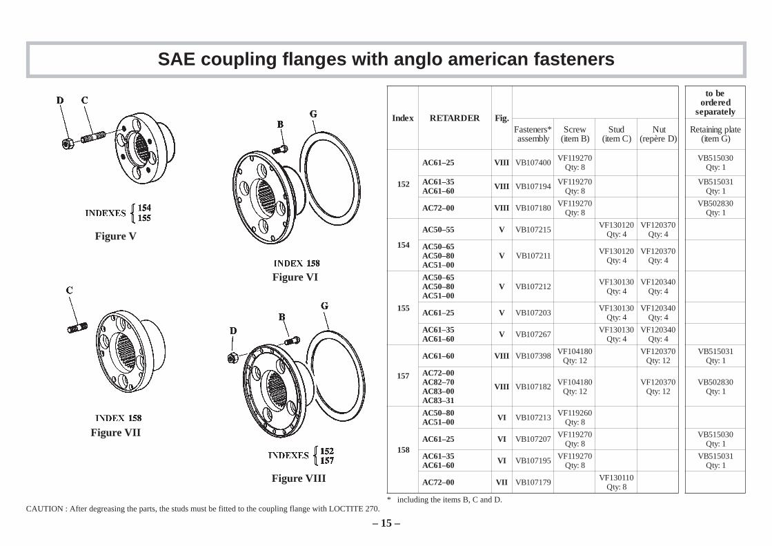
SAE coupling flanges with anglo american fasteners
xednI REDRATER .giF
ebotderedro
yletarapes
*srenetsaFylbmessa
wercS)Bmeti(
dutS)Cmeti(
tuN)Derèper(
etalpgniniateR)Gmeti(
251
52–16CA IIIV 004701BV 072911FV8:ytQ
030515BV1:ytQ
53–16CA06–16CA IIIV 491701BV 072911FV
8:ytQ130515BV
1:ytQ
00–27CA IIIV 081701BV 072911FV8:ytQ
038205BV1:ytQ
451
55–05CA V 512701BV 021031FV4:ytQ
073021FV4:ytQ
56–05CA08–05CA00–15CA
V 112701BV 021031FV4:ytQ
073021FV4:ytQ
551
56–05CA08–05CA00–15CA
V 212701BV 031031FV4:ytQ
043021FV4:ytQ
52–16CA V 302701BV 031031FV4:ytQ
043021FV4:ytQ
53–16CA06–16CA V 762701BV 031031FV
4:ytQ043021FV
4:ytQ
751
06–16CA IIIV 893701BV 081401FV21:ytQ
073021FV21:ytQ
130515BV1:ytQ
00–27CA07–28CA00–38CA13–38CA
IIIV 281701BV 081401FV21:ytQ
073021FV21:ytQ
038205BV1:ytQ
851
08–05CA00–15CA IV 312701BV 062911FV
8:ytQ
52–16CA IV 702701BV 072911FV8:ytQ
030515BV1:ytQ
53–16CA06–16CA IV 591701BV 072911FV
8:ytQ130515BV
1:ytQ
00–27CA IIV 971701BV 011031FV8:ytQ
CAUTION : After degreasing the parts, the studs must be fitted to the coupling flange with LOCTITE 270.
Figure V
Figure VI
Figure VII
Figure VIII
– 15 –
* including the items B, C and D.
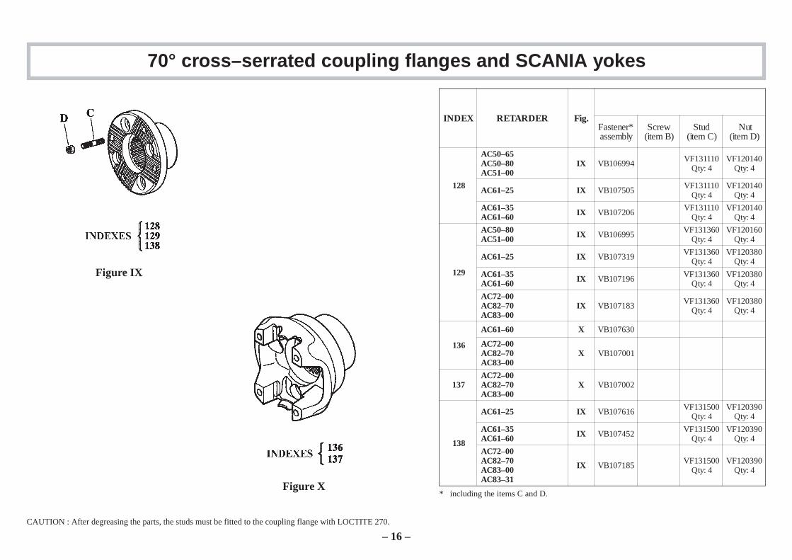
70° cross–serrated coupling flanges and SCANIA yokes
XEDNI REDRATER .giF*renetsaFylbmessa
wercS)Bmeti(
dutS)Cmeti(
tuN)Dmeti(
821
56–05CA08–05CA00–15CA
XI 499601BV 011131FV4:ytQ
041021FV4:ytQ
52–16CA XI 505701BV 011131FV4:ytQ
041021FV4:ytQ
53–16CA06–16CA XI 602701BV 011131FV
4:ytQ041021FV
4:ytQ
921
08–05CA00–15CA XI 599601BV 063131FV
4:ytQ061021FV
4:ytQ
52–16CA XI 913701BV 063131FV4:ytQ
083021FV4:ytQ
53–16CA06–16CA XI 691701BV 063131FV
4:ytQ083021FV
4:ytQ
00–27CA07–28CA00–38CA
XI 381701BV 063131FV4:ytQ
083021FV4:ytQ
631
06–16CA X 036701BV
00–27CA07–28CA00–38CA
X 100701BV
73100–27CA07–28CA00–38CA
X 200701BV
831
52–16CA XI 616701BV 005131FV4:ytQ
093021FV4:ytQ
53–16CA06–16CA XI 254701BV 005131FV
4:ytQ093021FV
4:ytQ
00–27CA07–28CA00–38CA13–38CA
XI 581701BV 005131FV4:ytQ
093021FV4:ytQ
CAUTION : After degreasing the parts, the studs must be fitted to the coupling flange with LOCTITE 270.
Figure IX
Figure X
– 16 –
* including the items C and D.
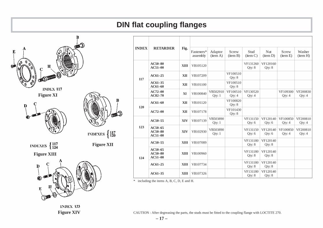
DIN flat coupling flanges
Figure XI
Figure XII
CAUTION : After degreasing the parts, the studs must be fitted to the coupling flange with LOCTITE 270.
XEDNI REDRATER .giF*srenetsaFylbmessa
rotpadA)Ameti(
wercS)Bmeti(
dutS)Cmeti(
tuN)Dmeti(
wercS)Emeti(
rehsaW)Hmeti(
711
08–05CA00–15CA IIIX 021501BV 062131FV
8:ytQ061021FV
8:ytQ
52–16CA IIX 902701BV 015001FV8:ytQ
53–16CA06–16CA IIX 001101BV 015001FV
8:ytQ
00–27CA07–28CA IX 048001BV 019205BV
1:ytQ015001FV
4:ytQ025031FV
4:ytQ003901FV
4:ytQ038002FV
4:ytQ
02106–16CA IIX 021101BV 028001FV
8:ytQ
00–27CA IIX 871701BV 034101FV8:ytQ
321
55–05CA VIX 931701BV 098305BV1:ytQ
051131FV6:ytQ
041021FV6:ytQ
058001FV4:ytQ
018002FV4:ytQ
56–05CA08–05CA00–15CA
VIX 039201BV 098305BV1:ytQ
051131FV6:ytQ
041021FV6:ytQ
058001FV4:ytQ
018002FV4:ytQ
421
55–05CA IIIX 980701BV 081131FV8:ytQ
041021FV8:ytQ
56–05CA08–05CA00–15CA
IIIX 069001BV 081131FV8:ytQ
041021FV8:ytQ
52–16CA IIIX 437701BV 081131FV8:ytQ
041021FV8:ytQ
53–16CA IIIX 623701BV 081131FV8:ytQ
041021FV8:ytQ
Figure XIII
Figure XIV– 17 –
* including the items A, B, C, D, E and H.
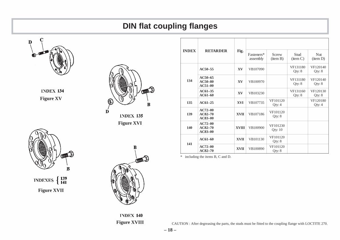
DIN flat coupling flanges
Figure XV
Figure XVI
Figure XVII
Figure XVIII CAUTION : After degreasing the parts, the studs must be fitted to the coupling flange with LOCTITE 270.
XEDNI REDRATER .giF*srenetsaFylbmessa
wercS)Bmeti(
dutS)Cmeti(
tuN)Dmeti(
431
55–05CA VX 090701BV 081131FV8:ytQ
041021FV8:ytQ
56–05CA08–05CA00–15CA
VX 079001BV 081131FV8:ytQ
041021FV8:ytQ
53–16CA06–16CA VX 032301BV 061131FV
8:ytQ031021FV
8:ytQ
531 52–16CA IVX 537701BV 021101FV4:ytQ
081021FV4:ytQ
93100–27CA07–28CA00–38CA
IIVX 681701BV 021101FV8:ytQ
04100–27CA07–28CA00–38CA
IIIVX 009001BV 032101FV01:ytQ
14106–16CA IIVX 031101BV 021101FV
8:ytQ
00–27CA07–28CA IIVX 098001BV 021101FV
8:ytQ
– 18 –
* including the items B, C and D.
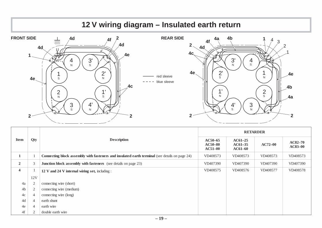
12 V wiring diagram – Insulated earth return
metI ytQ noitpircseD
REDRATER
56–05CA08–05CA00–15CA
52–16CA53–16CA06–16CA
00–27CA 07–28CA00–38CA
1 1 srenetsafhtiwylbmessakcolbgnitcennoC lanimrethtraedetalusnidna )42egapnosliatedees( 375804DV 375804DV 375804DV 375804DV
2 3 srenetsafhtiwylbmessakcolbnoitcnuJ )32egapnosliatedees( 093704DV 093704DV 093704DV 093704DV
4 1 ,tesgniriwlanretniV42dnaV21 gnidulcni : 575804DV 675804DV 775804DV 875804DV
V21
a4 2 )trohs(eriwgnitcennoc
b4 2 )muidem(eriwgnitcennoc
c4 4 )gnol(eriwgnitcennoc
d4 4 tnuhshtrae
e4 4 eriwhtrae
f4 2 eriwhtraeelbuod
1S
4N
2N
3S
3'S
2'N
1'S
4'N
4c
4e
4d4f
4d
1
4d
4e
2 2
2FRONT SIDE REAR SIDE
1
1'
N
N
2'S
2S
3'N
3N
4'S
4S
4d
4e
4a
4b
4c
4a 4b
4e
4f2
2 2
1
12
34
red sleeve
blue sleeve
– 19 –
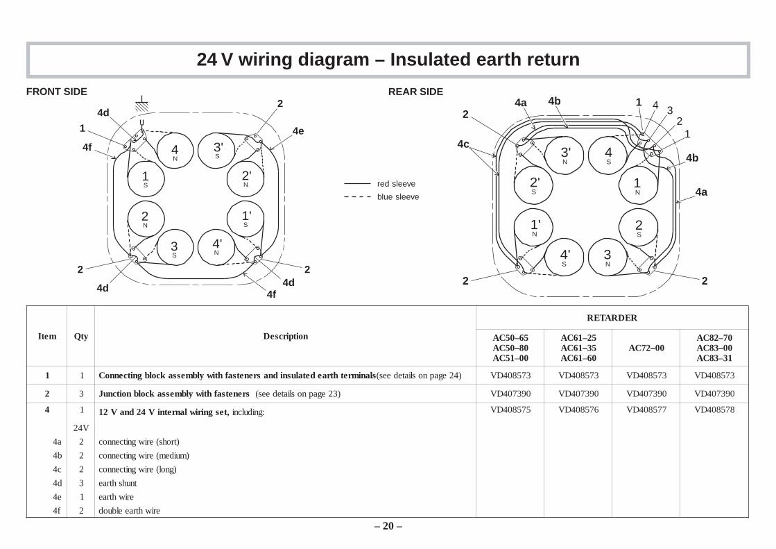
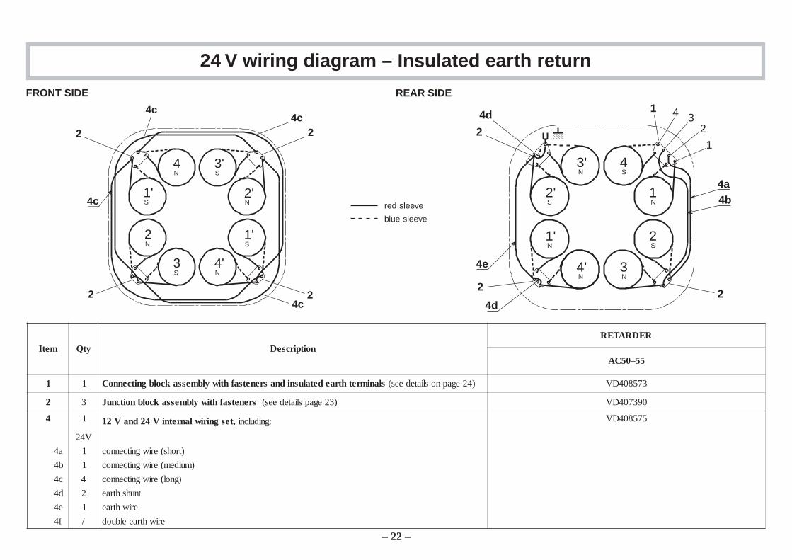
24 V wiring diagram – Insulated earth return
metI ytQ noitpircseD
REDRATER
56–05CA08–05CA00–15CA
52–16CA53–16CA06–16CA
00–27CA07–28CA00–38CA13–38CA
1 1 slanimrethtraedetalusnidnasrenetsafhtiwylbmessakcolbgnitcennoC )42egapnosliatedees( 375804DV 375804DV 375804DV 375804DV
2 3 srenetsafhtiwylbmessakcolbnoitcnuJ )32egapnosliatedees( 093704DV 093704DV 093704DV 093704DV
4 1 ,tesgniriwlanretniV42dnaV21 :gnidulcni 575804DV 675804DV 775804DV 875804DV
V42
a4 2 )trohs(eriwgnitcennoc
b4 2 )muidem(eriwgnitcennoc
c4 2 )gnol(eriwgnitcennoc
d4 3 tnuhshtrae
e4 1 eriwhtrae
f4 2 eriwhtraeelbuod
FRONT SIDE REAR SIDE
red sleeve
blue sleeve
– 20 –
4N
4'N
2N
2'N
1S
1'S
3'S
3S
4f
4e
4d
4f
1
2 2
2
4d 4d
1N
1'N
3'N
3N
2S
2'S
4S
4'S
4a
4b4c
4a 4b2
2 2
1
12
34
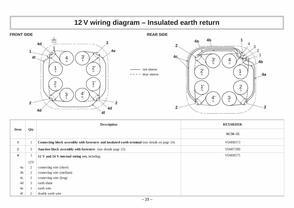
12 V wiring diagram – Insulated earth return
metI ytQnoitpircseD REDRATER
55–05CA
1 1 lanimrethtraedetalusnidnasrenetsafhtiwylbmessakcolbgnitcennoC )42egapnosliatedees( 375804DV
2 3 srenetsafhtiwylbmessakcolbnoitcnuJ )32egapsliatedees( 093704DV
4 1 ,tesgniriwlanretniV42dnaV21 :gnidulcni 575804DV
V21
a4 2 )trohs(eriwgnitcennoc
b4 2 )muidem(eriwgnitcennoc
c4 2 )gnol(eriwgnitcennoc
d4 3 tnuhshtrae
e4 1 eriwhtrae
f4 2 eriwhtraeelbuod
FRONT SIDE REAR SIDE
red sleeve
blue sleeve
– 21 –
4N
4'N
2N
2'N
1S
1'S
3'S
3S
4f
4e
4d
1
2 2
2
4f4d 4d
1N
1'N
3'N
3N
2S
2'S
4S
4'S
4a
4b4c
4a 4b2
2 2
1
12
34
24 V wiring diagram – Insulated earth return
metI ytQ noitpircseDREDRATER
55–05CA
1 1 slanimrethtraedetalusnidnasrenetsafhtiwylbmessakcolbgnitcennoC )42egapnosliatedees( 375804DV
2 3 srenetsafhtiwylbmessakcolbnoitcnuJ )32egapsliatedees( 093704DV
4 1 ,tesgniriwlanretniV42dnaV21 :gnidulcni 575804DV
V42
a4 1 )trohs(eriwgnitcennoc
b4 1 )muidem(eriwgnitcennoc
c4 4 )gnol(eriwgnitcennoc
d4 2 tnuhshtrae
e4 1 eriwhtrae
f4 / eriwhtraeelbuod
FRONT SIDE REAR SIDE
red sleeve
blue sleeve
– 22 –
2
2 2
2
4N
3'S
3S
4'N
2'N
1'S
2N
1'S4c
4c4c
4c
4d
4e
4d
4a4b
2
22
1
1
234
2'S
1'N
1N
2S
4'N
3N
3'N
4S
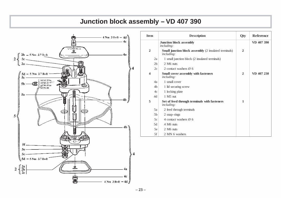
Junction block assembly – VD 407 390
metI noitpircseD ytQ ecnerefeR
ylbmessakcolbnoitcnuJ:gnidulcni
093704DV
2 ylbmessakcolbnoitcnujllamS )slanimretdetalusni2(:gnidulcni
2
a2 )slanimretdetalusni2(kcolbnoitcnujllams1
b2 stun6M2
c2 6Øsrehsawtcatnoc2
4 srenetsafhtiwylbmessarevocllamS:gnidulcni
2 032704DV
a4 revocllams1
b4 wercsgnirucesdil1
c4 etalpgnikcol1
d4 tun5M1
5 srenetsafhtiwslanimrethguorhtdeeffoteS:gnidulcni
1
a5 slanimrethguorhtdeef2
b5 sgnir–pans2
c5 6Øsrehsawtcatnoc4
d5 stun6M4
e5 stun6M2
f5 srehsaw6NM2
– 23 –
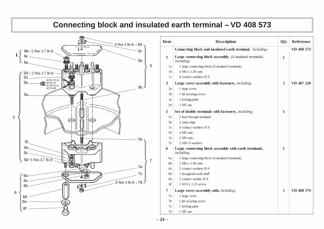
Connecting block and insulated earth terminal – VD 408 573
metI noitpircseD ytQ ecnerefeR
,lanimrethtraedetalusnidnakcolbgnitcennoC :gnidulcni 375804DV
1 egraL ylbmessakcolbgnitcennoc )slanimretdetalusni4(dulcni :gni
1
a1 )slanimretdetalusni4(kcolbgnitcennocegral1
b1 stun00.1x6M4
c1 6Øsrehsawtcatnoc4
3 ,srenetsafhtiwylbmessarevocegraL :gnidulcni 1 022704DVa3 revocegral1
b3 wercsgnirucesdil1
c3 etalpgnikcol1
d3 tun5M1
5 ,srenetsafhtiwslanimretelbuodfoteS :gnidulcni 1a5 slanimrethguorhtdeef2
b5 sgnir-pans2
c5 6Øsrehsawtcatnoc4
d5 stun6M4
e5 stun6M2
f5 srehsaw6NM2
6 ,slanimrethtraehtiwylbmessakcolbgnitcennocegraL:gnidulcni
1
a6 )slanimretdetalusni4(kcolbgnitcennocegral1
b6 stun00.1x6M2
c6 6Øsrehsawtcatnoc2
d6 ffumhtraelanogaxeh1
e6 8Ørehsawtcatnoc1
f6 wercs52.1x8M1
7 ylbmessarevocegraL ,htiw :gnidulcni 1 975804DVa7 revocegral1
b7 wercsgnirucesdil1
c7 etalpgnikcol1
d7 tun5M1
– 24 –
5a
5b5c5d
5f
5e5c
5d
3d
3c
3a
3b
3
5
6
6a6c6b
6d6e
6f
7
7a
7c
7d
7b
5 Nm 3.7 lb-ft
5 Nm 3.7 lb-ft
AC61-25 toAC83-31AC50-55 toAC51-00
5 Nm 3.7 lb-ft
4 Nm 3 lb-ft
4 Nm 3 lb-ft
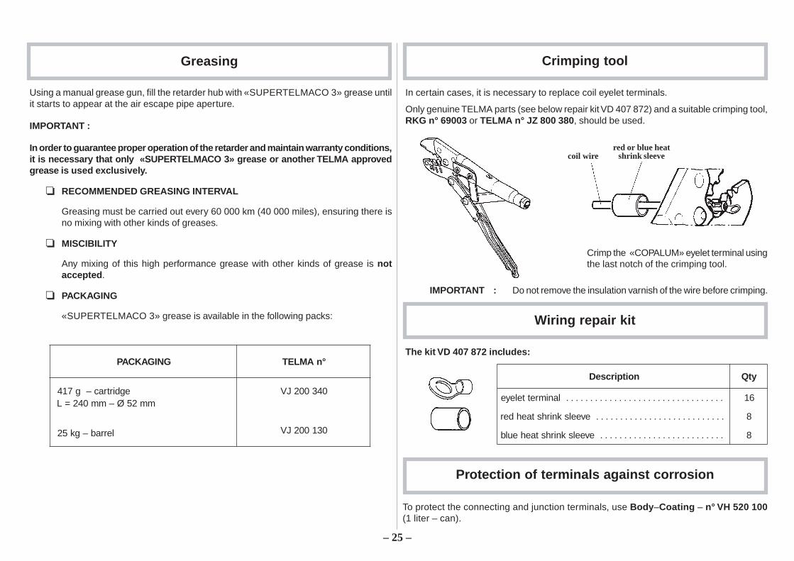
Greasing Crimping tool
Using a manual grease gun, fill the retarder hub with «SUPERTELMACO 3» grease untilit starts to appear at the air escape pipe aperture.
IMPORTANT :
In order to guarantee proper operation of the retarder and maintain warranty conditions,it is necessary that only «SUPERTELMACO 3» grease or another TELMA approvedgrease is used exclusively.
RECOMMENDED GREASING INTERVAL
Greasing must be carried out every 60 000 km (40 000 miles), ensuring there isno mixing with other kinds of greases.
MISCIBILITY
Any mixing of this high performance grease with other kinds of grease is notaccepted .
PACKAGING
«SUPERTELMACO 3» grease is available in the following packs:
GNIGAKCAP °nAMLET
egdirtrac–g714mm25Ø–mm042=L
043002JV
gk52 – lerrab 031002JV
In certain cases, it is necessary to replace coil eyelet terminals.
Only genuine TELMA parts (see below repair kit VD 407 872) and a suitable crimping tool,RKG n° 69003 or TELMA n° JZ 800 380 , should be used.
IMPORTANT : Do not remove the insulation varnish of the wire before crimping.
Crimp the «COPALUM» eyelet terminal usingthe last notch of the crimping tool.
The kit VD 407 872 includes:
Wiring repair kit
noitpircseD ytQ
.................................lanimretteleye 61
...........................eveelsknirhstaehder 8
eveelsknirhstaeheulb .......................... 8
Protection of terminals against corrosion
To protect the connecting and junction terminals, use Body –Coating – n° VH 520 100(1 liter – can).
coil wirered or blue heat
shrink sleeve
– 25 –
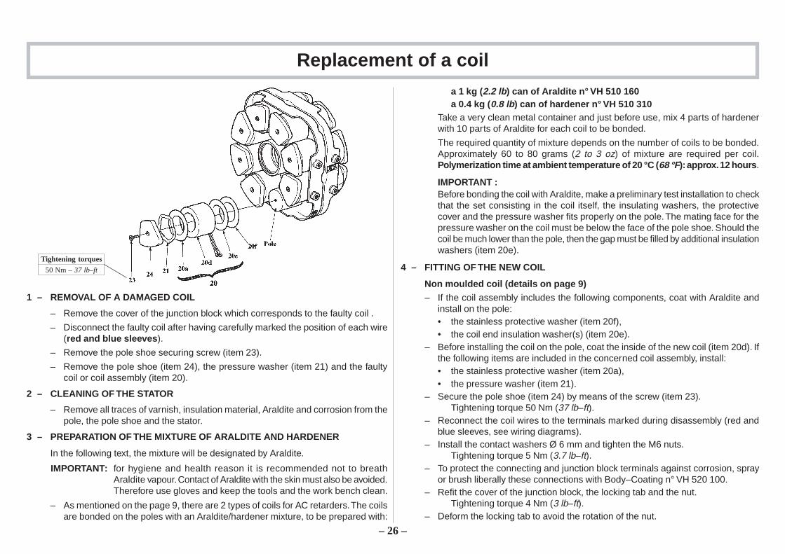
Replacement of a coil
1 – REMOVAL OF A DAMAGED COIL
– Remove the cover of the junction block which corresponds to the faulty coil .
– Disconnect the faulty coil after having carefully marked the position of each wire(red and blue sleeves ).
– Remove the pole shoe securing screw (item 23).
– Remove the pole shoe (item 24), the pressure washer (item 21) and the faultycoil or coil assembly (item 20).
2 – CLEANING OF THE STATOR
– Remove all traces of varnish, insulation material, Araldite and corrosion from thepole, the pole shoe and the stator.
3 – PREPARATION OF THE MIXTURE OF ARALDITE AND HARDENER
In the following text, the mixture will be designated by Araldite.
IMPORTANT: for hygiene and health reason it is recommended not to breathAraldite vapour. Contact of Araldite with the skin must also be avoided.Therefore use gloves and keep the tools and the work bench clean.
– As mentioned on the page 9, there are 2 types of coils for AC retarders. The coilsare bonded on the poles with an Araldite/hardener mixture, to be prepared with:
a 1 kg (2.2 lb) can of Araldite n° VH 510 160a 0.4 kg (0.8 lb) can of hardener n° VH 510 310
Take a very clean metal container and just before use, mix 4 parts of hardenerwith 10 parts of Araldite for each coil to be bonded.
The required quantity of mixture depends on the number of coils to be bonded.Approximately 60 to 80 grams (2 to 3 oz) of mixture are required per coil.Polymerization time at ambient temperature of 20 °C ( 68 °F): approx. 12 hours .
IMPORTANT :Before bonding the coil with Araldite, make a preliminary test installation to checkthat the set consisting in the coil itself, the insulating washers, the protectivecover and the pressure washer fits properly on the pole. The mating face for thepressure washer on the coil must be below the face of the pole shoe. Should thecoil be much lower than the pole, then the gap must be filled by additional insulationwashers (item 20e).
4 – FITTING OF THE NEW COIL
Non moulded coil (details on page 9)– If the coil assembly includes the following components, coat with Araldite and
install on the pole:• the stainless protective washer (item 20f),• the coil end insulation washer(s) (item 20e).
– Before installing the coil on the pole, coat the inside of the new coil (item 20d). Ifthe following items are included in the concerned coil assembly, install:• the stainless protective washer (item 20a),• the pressure washer (item 21).
– Secure the pole shoe (item 24) by means of the screw (item 23).Tightening torque 50 Nm (37 lb–ft).
– Reconnect the coil wires to the terminals marked during disassembly (red andblue sleeves, see wiring diagrams).
– Install the contact washers Ø 6 mm and tighten the M6 nuts.Tightening torque 5 Nm (3.7 lb–ft).
– To protect the connecting and junction block terminals against corrosion, sprayor brush liberally these connections with Body–Coating n° VH 520 100.
– Refit the cover of the junction block, the locking tab and the nut.Tightening torque 4 Nm (3 lb–ft).
– Deform the locking tab to avoid the rotation of the nut.
Tightening torques
50 Nm – 37 lb–ft
– 26 –

28, rue Paul Painlevé – Z.A. du Vert GalantF–95310 SAINT OUEN L’AUMONE – FRANCEB.P. 692 F–95004 CERGY Cedex – FRANCE
Tel. (+33) (0) 1 34 48 54 00 – Fax : (+33) (0) 1 30 37 63 69
TELMA S.A. au capital de 163 603 000 FSiège Social : 28, rue Paul Painlevé – F95310 Saint Ouen l’Aumône410 163 125 – R.C.S. Pontoise
This technical data is supplied for your guidance in the use of the product and may be modified at anymoment without prior notice.Any reproduction, duplication or translation of this publication, also in the form of an abstract, issubject to the previous written permission of TELMA, Cergy.
Printed in France