*tm 10-8465-236-10 · · 2014-02-24om unique logistics support applications (tulsa) ... . 0015 ....
TRANSCRIPT

*TM 10-8465-236-10TECHNICAL MANUAL
OPERATOR’S MANUAL FOR
MODULAR LIGHTWEIGHT LOAD-CARRYING EQUIPMENT
(MOLLE) II
* This manual supersedes TM 10-8465-236-10, 2 November 2009.
DISTRIBUTION STATEMENT A. Approved for public release; distribution is unlimited.
HEADQUARTERS, DEPARTMENT OF THE ARMY
20 JUNE 2013


WARNING SUMMARY
a
This warning summary contains general safety warnings and hazardous material warnings that must be understood and applied during operation and maintenance of this equipment. Failure to observe these precautions could result in serious injury or death to personnel. Also included are explanations of safety and hazardous materials icons used within the technical manual.
For first aid information, refer to FM 4-25.11.
EXPLANATION OF SAFETY WARNING ICONS
HEAVY OBJECT – Human figure stooping over heavy object shows physical injury potential from improper lifting technique.
GENERAL SAFETY WARNINGS DESCRIPTION
WARNING
Components of the MOLLE II, once loaded for operation, may be heavy and require proper lifting technique in order to avoid injury.
EXPLANATION OF HAZARDOUS MATERIALS ICONS
BIOLOGICAL – biohazard symbol means that contact with nuclear or biological material can cause harm to the equipment or the user.
CHEMICAL – drops of liquid on hand shows that the material will cause burns or irritation to human skin or tissue.
FIRE – flame shows that a material may ignite and cause burns.
HAZARDOUS MATERIALS DESCRIPTIONS
WARNING
Dispose of in accordance with FM 3-11.5 if exposed to any chemical, biological, radiological, or nuclear (CBRN) elements.

b
WARNING
Improper cleaning methods or use of unauthorized cleaning liquids, solvents, dry cleaning, or drying clothes in a dryer can injure personnel or damage the MOLLE II. Failure to follow these instructions could result in harm to the Soldier.
WARNING
Do not store equipment in containers that could trap moisture. Failure to follow this warning may result in degradation of the equipment.

*TM 10-8465-236-10
i
HEADQUARTERS DEPARTMENT OF THE ARMY
WASHINGTON D.C., 20 JUNE 2013
TECHNICAL MANUAL
OPERATOR’S MANUAL FOR
MODULAR LIGHTWEIGHT LOAD-CARRYING EQUIPMENT
(MOLLE) II
* This manual supersedes TM 10-8465-236-10, 2 November 2009.
DISTRIBUTION STATEMENT A. Approved for public release; distribution is unlimited.
REPORTING ERRORS AND RECOMMENDING IMPROVEMENTS
You can help improve this manual. If you find any errors, or if you would like to recommend any improvements to the procedures in this publication, please let us know. The preferred method is to submit your DA Form 2028 (Recommended Changes to Publications and Blank Forms) through the Internet on the TACOM Unique Logistics Support Applications (TULSA) Web site. The Internet address is: https://tulsa.tacom.army.mil. Access to all applications requires CAC authentication, and you must complete the Access Request form the first time you use it. The DA Form 2028 is located under the TULSA Applications on the left-hand navigation bar. Fill out the form and click on SUBMIT. Using this form on the TULSA Web site will enable us to respond more quickly to your comments and to better manage the DA Form 2028 program. You may also mail, e-mail, or fax your comments or DA Form 2028 directly to the U.S. Army TACOM Life Cycle Management Command. The postal mail address is U.S. Army TACOM Life Cycle Management Command, ATTN: AMSTA-LCL-MPP/TECH PUBS, MS 727, 6501 E. 11 Mile Road, Warren, MI 48397-5000. The e-mail address is: [email protected]. The fax number is DSN 786-1856 or Commercial (586)282-1856. A reply will be furnished to you.

TABLE OF CONTENTS
ii
WP Sequence No.
Chapter 1 – General Information, Equipment Description, and Theory of Operation
General Information ....................................................................... 0001
Equipment Description and Data .................................................. .0002
Theory of Operation ....................................................................... 0003
Chapter 2 – Operator Instructions
Operation Under Usual Conditions Sizing and Fitting Instructions – FLC ............................................. 0004
Operation Under Usual Conditions Sizing and Fitting Instructions –TAP .............................................. 0005
Operation Under Usual Conditions Pouch/Pocket Attachment ............................................................. 0006
Operation Under Usual Conditions Canteen/General Purpose Pouch .................................................. 0007
Operation Under Usual Conditions Large and Medium Suspension Systems ...................................... 0008
Operation Under Usual Conditions Assault Pack .................................................................................. 0009
Operation Under Usual Conditions Bandoleer ...................................................................................... 0010
Operation Under Usual Conditions Waist Pack..................................................................................... 0011
Operation Under Usual Conditions MOLLE II Large Frame .................................................................. 0012
Operation Under Usual Conditions MOLLE II Medium Frame .............................................................. 0013
Operation Under Usual Conditions Radio Pocket …………………………………………………………...0014

iii/iv blank
WP Sequence No.
Chapter 3 – Troubleshooting Procedures
Operator Maintenance Troubleshooting………………………………………………………. 0015
Chapter 4 – Operator Maintenance Instructions
Operator Maintenance MOLLE II and Hydration System Inspect, Clean ............................................................................... 0016
Operator Maintenance MOLLE II Buckles Inspect, Replace............................................................................ 0017
Chapter 5 – Supporting Information
References .................................................................................... 0018
Components of End Item (COEI) and Basic Issue Items (BII) Lists ................................................... 0019
Additional Authorization List .......................................................... 0020
Expendable and Durable Items List............................................... 0021

CHAPTER 1 – GENERAL INFORMATION, EQUIPMENT DESCRIPTION, AND THEORY OF OPERATION 0001
GENERAL INFORMATION
0001-1
SCOPE
This manual covers the fitting and use instruction for the Modular Lightweight Load-Carrying Equipment (MOLLE) II.
MAINTENANCE, FORMS, RECORDS AND REPORTS
Department of the Army forms and procedures used for equipment maintenance will be those prescribed by DA PAM 750-8, The Army Maintenance Management System (TAMMS) Users Manual, DA PAM 738-751, Functional Users Manual for the Army Maintenance Management System (TAMMS-A), or AR 700-138, Army Logistics Readiness and Sustainability.
REPORTING EQUIPMENT IMPROVEMENT RECOMMENDATIONS (EIR)
If your MOLLE II needs improvement, let us know. Send us an EIR. You, the user, are the only one who can tell us what you do not like about your equipment. Let us know why you do not like the design or performance. If you have Internet access, the easiest and fastest way to report problems or suggestions is to follow the instructions and links below:
For ALL non-Aviation/Missile Warranty, EIR and PQDRs, submit through the Web Product Quality Deficiency Reporting (PQDR) site. The Web PQDR Web site is: http://www.nslcptsmh.csd.disa.mil/webpqdr/webpqdr.htm.
New accounts can be established at the following address: http://www.nslcptsmh.csd.disa.mil/accessforms/uarform.htm.
All AMCOM (Aviation and Missile Command) Deficiency Reports (DRs), (Warranty, EIR, and PQDRs) must be submitted through the Joint Deficiency Reporting System (JDRS) at https://jdrs.mil/DR_Initiate.cfm?service=AR
You may also submit your information using an SF 368 (Product Quality Deficiency Report). You can send your SF 368 using e-mail, regular mail, or fax using the addresses/fax numbers specified in (DA PAM 750-8, The Army Maintenance Management System (TAMMS) Users Manual OR DA PAM 738-751, Functional Users Manual for the Army Maintenance Management Systems – Aviation (TAMMS-A) for aviation systems). We will send you a reply.
CORROSION PREVENTION AND CONTROL (CPC)
Corrosion Prevention and Control (CPC) of Army materiel is a continuing concern. It is important that any corrosion or degradation problems with this item be reported so that the problem can be corrected and improvements can be made to prevent the problem in future items. Corrosion specifically occurs with metals. It is an electrochemical process that causes the degradation of metals. It is commonly

0001-2
caused by exposure to moisture, acids, bases, or salts. An example is the rusting of iron. Corrosion damage in metals can be seen, depending on the metal, as tarnishing, pitting, fogging, surface residue, and/or cracking. Plastics, composites, and rubbers can also degrade. Degradation is caused by thermal (heat), oxidation (oxygen), solvation (solvents), or photolytic (light, typically ultraviolet) processes. The most common exposures are excessive heat or light. Damage from these processes will appear as cracking, softening, swelling, and/or breaking.
SF 368, Product Quality Deficiency Report, should be submitted to the address specified in DA PAM 750-8, The Army Maintenance Management System (TAMMS) Users Manual.
DESTRUCTION OF ARMY MATERIEL TO PREVENT ENEMY USE
Not applicable to the MOLLE II system.
PREPARATION FOR STORAGE OR SHIPMENT
The MOLLE II is shipped in sealed plastic. Do not store the MOLLE II in any medium that could trap moisture and cause degradation of the equipment. Make sure components are packed in airtight or moisture-free environment for long-time storage or for shipment.
NOMENCLATURE CROSS-REFERENCE LIST
LIST OF ABBREVIATIONS/ACRONYMS
TERM DEFINITION
AAL Additional Authorized List
ALICE All-Purpose Lightweight Individual Carrying Equipment
AN/PVS Army/Navy Portable Visual Search (see MNVD)
APD Army Publishing Directorate
AR Army Regulation
ASIP Advanced SINCGARS Improvement Program
BII Basic Issue Items
BT Bottle
OFFICIAL NOMENCLATURE COMMON NAME Ladder-Lock Buckle Non-Slip Buckle Slide Fastener Zipper Waist Belt Hip Belt Female Side-Release Buckle Quasm Buckle

0001-3
TERM DEFINITION
CAGEC Commercial and Government Entity Code
CBRN Chemical, Biological, Radiological, and Nuclear
CIF Central Issue Facility
COEI Components of End Items
CPC Corrosion Prevention and
CTA Common Tables of Allowances
DA Department of the Army
DAGR Defense Advanced GPS Receiver
DOL-W Director of Logistics-Washington
EIR Equipment Improvement Recommendations
EA Each
ETLBV Enhanced Tactical Load-Bearing Vest
FLC Fighting Load Carrier
FM Field Manual
GP General Purpose
GPS Global Positioning System
IAW In Accordance With
IFAK Individual First Aid Kit
IOTV Improved Outer Tactical Vest
JTA Joint Table of Allowances
MBITR Multiband Inter/Intra Team Radio
MDD Media Distribution Division
MNVD Monocular Night Vision Device
MVP MOLLE Vehicle Pane

0001-4
TERM DEFINITION
MOLLE Modular Lightweight Load-Carrying Equipment
MOS Military Occupational Specialty
MTOE Modified Table of Organization and Equipment
NO Number
PAM Pamphlet
NSN National Stock Number
PMCS Preventive Maintenance Checks and Services
PVS Portable Visual Search (Night Vision Goggles)
PQDR Product Quality Deficiency Report
SAW Squad Automatic Weapon
SE Set
SINCGARS Single-Channel Ground-Air Radio System
SF Standard Form
SOP Standard Operating Procedure
SPCS Soldier Plate Carrier System
TAMMS The Army Maintenance Management System
TAMMS-A Functional Users Manual for the Army Maintenance System
TAP Tactical Assault Panel
TDA Table of Distribution and Allowances
TM Technical Manual
TOE Table of Organization and
WCA Warranty Claim Action
WP Work Package
END OF WORK PACKAGE
0002 EQUIPMENT DESCRIPTION AND DATA
0002-1
INTRODUCTION
The MOLLE II is an integrated, modular load-bearing system designed to have different configurations that allow Soldiers to tailor their equipment to meet specific mission needs.
The MOLLE II system is configured from the following items: Tactical Assault Panel (TAP) (WP 0019, Item 2), the Fighting Load Carrier (FLC) (WP 0019, Item 10), Assault Pack (WP 0019, Item 15), Waist Pack (WP 0019, Item 16), Hydration Systems (WP 0019, Items 20 and 25), Large Pack (WP 0019, Item 31) with an external frame ( WP 0019, Item 33) and webbing to accommodate added components, the Medium Pack (WP 0019, Item 39), compatible pouches and pockets, and additional items to assist in meeting mission requirements.
The MOLLE II system sets are the Rifleman Set with TAP (WP 0019, Item 1) and Rifleman Set with FLC (WP 0019, Item 8), Large Rucksack Set (WP 0019, Item 30), Medium Rucksack Set (WP 0019, Item 38), Pistolman Set (WP 0019, Item 43), SAW Gunner Set (WP 0019, Item 46), Grenadier Set (WP 0019, Item 49), and the Medic Set (WP 0019, Item 53).
The MOLLE II is made from water-repellant fabrics and composites that are military specified.
MOLLE II is a modular load-bearing system designed to enhance the survivability and lethality of the modern Soldier.
MOLLE II is a replacement for the All-Purpose Lightweight Individual Carrying Equipment (ALICE) system and the Integrated Individual Fighting System, including the Enhanced Tactical Load-Bearing Vest (ETLBV).
Your Central Issue Facility (CIF) or Supply will issue all Soldiers a complete MOLLE II Rifleman set. The appropriate pouches/pockets that match your issued weapon will be issued at the unit level. All pockets can be attached to FLC or TAP.
Fighting Load Carrier (FLC)
The Fighting Load Carrier (FLC) (WP 0019, Item 10) is a modular vest that allows the user to tailor the load to meet mission need without unnecessary pouches and gear. It is one size fits all and is designed to be worn over body armor. The MOLLE II pockets can be placed directly on the body armor for certain missions; however, when the pockets are placed directly on the armor, it limits the ability to take the fighting load off without exposing oneself to ballistic threats.
0002-2
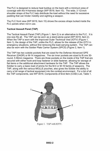
The FLC is designed to reduce heat buildup on the back with a minimum area of coverage with the H-harness design (WP 0019, Item 10). The wide, 3 1/2-inch shoulder straps of the FLC help distribute the load without the need for excessive padding that can hinder mobility and sighting a weapon. The FLC front view (WP 0019, Item 10) shows the excess straps tucked inside the FLC panels when not in use. Tactical Assault Panel (TAP) The Tactical Assault Panel (TAP) (Figure 1, Item 2) is an alternative to the FLC. It is one size fits all. The TAP can be worn as a stand-alone panel (WP 0019, Item 2). When the TAP is worn with the Improved Outer Technical Vest (IOTV) (Figure 1, Item 1), the design of the TAP, unlike the FLC, allows for the release of the IOTV in emergency situations, without first removing the load-carrying system. The TAP can also be worn with the Soldier Plate Carrier System (SPCS) (Figure 2, Item 1). The TAP has two outside pockets that are sized for the Defense Advanced GPS Receiver (DAGR) or M-14 magazines. The six inner pockets are sized to fit one 30-round, 5.56mm magazine. There are three pockets on the inside of the TAP that are secured with either hook-and-loop fastener or slide fastener, allowing for storage of flat items or the additional attachment hardware for the TAP. The TAP allows the Soldier to carry a basic load of ammo for the M-4 or M-16 family of weapons. The TAP, along with the various MOLLE pouches, also gives the Soldier the ability to carry a full range of tactical equipment into the combat environment. For a list of all the TAP components, see WP 0019, Components of End Item (COEI) List, Table 1.
Figure 1. TAP with IOTV.
1
2

0002-3
Figure 2. TAP with SPCS. POCKETS/POUCHES A common FLC vest or TAP is provided for all Soldiers with specialized removable pouches/pockets for Rifleman Set, Pistolman Set, Squad Automatic Weapon (SAW) Gunner Set, Grenadier Set, and Medic Set configurations. See WP 0019, “Components of End Item (COEI) List,” Table 1, for illustrations of pouches/pockets for each set. There are other accessories/components that may be used according to mission need, Table 1 below. For more details on these items, refer to “Additional Authorization List,” WP 0020.
Table 1. Accessories/Components.
ALICE Six-Magazine K-Bar 300-Round, M-240 Adapter Bandoleer Adapter Ammunition Bag
1

0002-4
Table 1. Accessories/Components. – Continued
Sustainment Pouch Leader Pocket
Chaplain Pocket Radio Pouch
Admin Pocket Modular Medic Pouch
Vehicle Panel Medical Bag Panel 12-Gauge Shotgun

0002-5
MOLLE II CONFIGURATIONS Get to know your MOLLE II system and experiment with different load configurations that comprise the various MOLLE II sets. The Soldier may remove components to streamline the load. All configurations are comprised of a separate FLC or TAP and various other items, such as pouches, to make up the configuration. FLC Complete is illustrated in the Components of End Item (COEI) List, Table 1 (WP 0019, Items 9 through 14). Rifleman Configuration The Rifleman configuration is designed to hold up to 12 magazines in three M4, two-magazine pouches and two M4, three-magazine side-by-side pouches. The set holds grenades in two fragmentation hand grenade pouches. The two canteen/general purpose pouches are for canteens or other items. The Rifleman configuration can be worn with the FLC (WP 0019, Items 8 through 14). The Rifleman configuration can also be worn with the TAP (WP 0019, Items 1 through 7). Pistolman Configuration The Pistolman configuration (WP 0019, Items 43 through 45) holds four, single 9mm magazine pouches and two fragmentation hand grenades, and can be worn with FLC or with TAP. Pistolman configuration shown with FLC in WP 0019.
SAW Gunner Configuration The Squad Automatic Weapon (SAW) Gunner configuration (WP 0019, Items 46 through 48) accommodates two 200-round magazine pouches, two 100-round magazine pouches, and can be worn with FLC or TAP. SAW Gunner configuration shown with FLC in WP 0019. Grenadier Configuration The Grenadier configuration (WP 0019, Items 49 through 52) consists of ten 40mm single, high explosive grenade pouches, two double-high explosive grenade pouches, and two double-pyrotechnic round pouches. The three-magazine side-by-side pouches will allow the user to carry a basic load of M4 ammunition and place the 40mm pouches over the top. The Grenadier can be worn with FLC or TAP. Grenadier configuration shown with FLC in WP 0019. Medic Configuration The Medic configuration (WP 0019, Items 53 through 57) will receive four zippered medical pouches for the vest and three M4, two-magazine pouches and can be worn with FLC or TAP. There is also a specialized panel-loading medical bag that has an additional four removable medical pouches attached to it.
0002-6
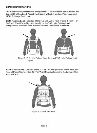
LOAD CONFIGURATIONS There are several possible load configurations. Four common configurations are the Light Fighting Load, Assault Pack Load, MOLLE II Medium Pack Load, and MOLLE II Large Pack Load: Light Fighting Load. Consists of the FLC with Waist Pack (Figure 3, Item 1) or TAP with Waist Pack (Figure 3, Item 2). In the TAP Light Fighting Load configuration, the Waist Pack attaches with the stand-alone Waist Belt.
Figure 3. FLC Light Fighting Load (Left) and TAP Light Fighting Load (Right).
Assault Pack Load. Consists of the FLC or TAP with pouches, Waist Pack, and Assault Pack (Figure 4, Item 1). The Waist Pack is attached to the bottom of the Assault Pack.
Figure 4. Assault Pack Load.
1 2
1

0002-7
MOLLE II Medium Pack Load. Consists of the FLC or TAP and Medium Pack (Figure 5, Item 1).
Figure 5. MOLLE II Medium Pack Load.
MOLLE II Large Pack Load. Consists of the FLC or TAP, Waist Pack (Figure 6, Item 3), Assault Pack (Figure 6, Item 1), and Large Pack (Figure 6, Item 2). The Waist Pack is carried on the bottom of the Large Pack.
The Waist Pack must be removed from back of FLC to effectively carry MOLLE II Medium or Large Pack.
Figure 6. MOLLE II Large Pack Load.
1
1
3
2
0002-8
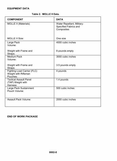
EQUIPMENT DATA
Table 2. MOLLE II Data.
END OF WORK PACKAGE
COMPONENT DATA
MOLLE II (Materials) Water Repellant, Military-Specified Fabrics and Composites
MOLLE II Size: One size Large Pack Volume: Weight with Frame and Straps:
4000 cubic inches 8 pounds empty
Medium Pack Volume: Weight with Frame and Straps:
3000 cubic inches 3.5 pounds empty
Fighting Load Carrier (FLC) Weight with Rifleman Pouches:
4 pounds
Tactical Assault Panel (TAP) Weight with Harness:
1.4 pounds
Large Pack Sustainment Pouch Volume:
500 cubic inches
Assault Pack Volume:
2000 cubic inches

0003 THEORY OF OPERATION
0003-1/2 blank
INTRODUCTION This work package discusses the theory of operation for the MOLLE II. MOLLE II is a modular load-carrying system for Soldiers which will enhance their survivability, mobility, and lethality. The modularity permits tailoring for mission requirements and minimizes the combat load. The MOLLE II is designed as a replacement to the All-Purpose Lightweight Individual Carrying Equipment (ALICE) system. END OF WORK PACKAGE


CHAPTER 2 – OPERATOR INSTRUCTIONS 0004 OPERATION UNDER USUAL CONDITIONS
SIZING AND FITTING INSTRUCTIONS – FLC
0004-1
INITIAL SETUP: Not Applicable SIZING AND FITTING This work package provides instructions for fitting your MOLLE II properly.
Fighting Load Carrier (FLC) Adjustments Size adjustments to the vest are made in the following manner:
1. Remove the stiffened webbing adjustment tabs from the two slots on the vest belt.
2. Extend the 1 1/2-inch straps (so only 4-6 inches of free-running strap
extend beyond) on the front of the vest to allow the vest panels to move freely on the hip belt.
3. Place the vest on the body.
4. Secure the slide fastener on front of FLC to assist with reinsertion of
stiffened strap webbing.
5. Reinsert the stiffened strap webbing tabs on the back of the belt in the appropriate location (Figure 1, Item 1), ensuring the stiffened webbing adjustment tabs are positioned the same on each side.
Figure 1. FLC Adjustment Tabs.
END OF TASK
1

0004-2
Fighting Load Carrier (FLC) Adjustments - Narrow Torsos
NOTE
The metal friction buckles on the belt are not used with narrow waists. The buckles are shown for clarity in the illustration (Figure 2). When buckles are properly adjusted for narrow waists, they will be hidden inside the vest panel tunnels. To fit extremely narrow torsos:
1. Remove the 1-inch webbing from all four metal friction buckles on the back of the vest. The elastic keeper (Figure 2, Item 2) will be removed when the webbing is removed from the buckle.
2. Place the elastic keeper back on webbing (Figure 2, Item 1).
Figure 2. Placement of Elastic Keepers on Webbing.
1
2

0004-3
3. Run the webbing (Figure 3, Item 1) back through buckle (Figure 3, Item 2) on the vest at the top.
Figure 3. Webbing through Buckle on FLC.
4. Remove the stiffened adjustment tabs from the loops. 5. Slide the vest panels toward the center back of the belt until a proper
fit is achieved. 6. Secure the stiffened adjustment tabs (Figure 4, Item 1), and wear the
vest as shown.
Figure 4. Stiffened Adjustment Tabs.
1 2
1

0004-4
7. Secure loose ends of 1-inch webbing with the elastic keepers. END OF TASK
Stowing the Waist Belt Webbing and Side-Release Buckle
NOTE
The Waist Belt webbing is located behind the zipper, on the front of the FLC.
1. Once the belt is adjusted properly, adjust the waist belt webbing by pulling it tight through its keeper buckle, ensuring the free-running webbing is run back through the keeper buckle (Figure 6, Item 1).
2. Secure free-running end of the webbing (Figure 5, Item 1).
Figure 5. Free-Running Ends of Excess Webbing Rolled and Stowed.
1
0004-5
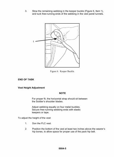
3. Stow the remaining webbing in the keeper buckle (Figure 6, Item 1), and tuck free-running ends of the webbing in the vest panel tunnels.
Figure 6. Keeper Buckle. END OF TASK
Vest Height Adjustment
NOTE
For proper fit, the horizontal strap should sit between the Soldier’s shoulder blades. Adjust webbing equally on four metal buckles. Secure free-running webbing ends with elastic keepers or tape.
To adjust the height of the vest:
1. Don the FLC vest.
2. Position the bottom of the vest at least two inches above the wearer’s hip bones, to allow space for proper use of the pack hip belt.
1

0004-6
3. Adjust the webbing equally on the four metal buckles (circled below) on the back of the vest.
4. Secure the free-running ends of all webbing with the elastic keepers
(Figure 7, Item 1) or tape.
Figure 7. Secured Free-Running Ends in Elastic Keepers.
END OF TASK END OF WORK PACKAGE
1

0005 OPERATION UNDER USUAL CONDITIONS
SIZING AND FITTING INSTRUCTIONS – TAP
0005-1
INITIAL SETUP: Not Applicable SIZING AND FITTING This work package provides instructions for fitting your MOLLE II Tactical Assault Panel (TAP) (Figure 1, Item 4) as a stand-alone system (Figure 2, Item 1) or as worn with the Improved Outer Tactical Vest (IOTV) or as worn with the Soldier Plate Carrier System (SPCS). Components of the TAP include on left side adapter web (Figure 1, Item 1), one right side adapter web (Figure 1, Item 5), two SPCS adapters (Figure 1, Item 2), and two quasm buckles (Figure 1, Item 3).
Figure 1. Tactical Assault Panel (TAP) with Components.
1 2
5 3
4
0005-2
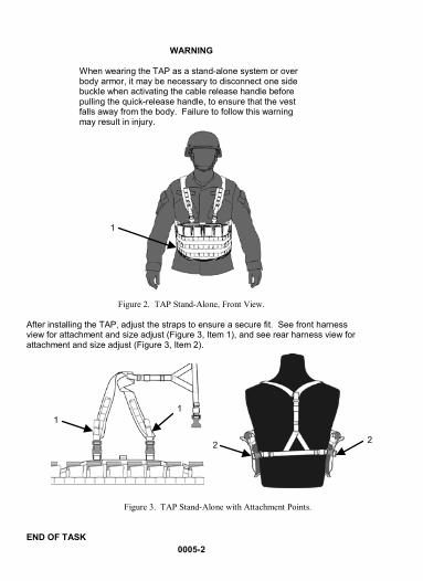
WARNING
When wearing the TAP as a stand-alone system or over body armor, it may be necessary to disconnect one side buckle when activating the cable release handle before pulling the quick-release handle, to ensure that the vest falls away from the body. Failure to follow this warning may result in injury.
Figure 2. TAP Stand-Alone, Front View.
After installing the TAP, adjust the straps to ensure a secure fit. See front harness view for attachment and size adjust (Figure 3, Item 1), and see rear harness view for attachment and size adjust (Figure 3, Item 2).
Figure 3. TAP Stand-Alone with Attachment Points.
END OF TASK
2 2
1 1
1

0005-3
TAP to IOTV There are four attachment points required for properly attaching the TAP to the IOTV:
• Two D-rings (Figure 4, Item 1) located near the top of the front carrier. • Two female attachment buckles (Figure 4, Item 2) on the side plate
carriers.
Figure 4. IOTV Attachment Points for TAP.
You will need to use the two D-ring adapter webs (Figure 5, Items 1 and 3), which come with the TAP, if there are no D-rings present on your vest. You will also need the two female quasm buckles (Figure 5, Item 2).
Figure 5. TAP Adapter Webs and Quasm Buckles for Attachment to IOTV.
1
3 2
1a
1 2

0005-4
NOTE
It will be necessary to prevent the hook from attaching to the pile, in order to pass pile through webbing loop.
1. Open the hook-and-pile flap (Figure 4, Item 1a) on the left shoulder (left side when worn) of the vest.
2. Secure the hook-and-pile D-ring adapter web (Figure 4, Item 1) so the D-ring is fully exposed from under the flap, when flap is closed.
3. Pass the “pile” portion (on the right shoulder when worn) of the adapter
web under the entire shoulder portion of the body armor.
4. Then pass the “pile” portion through the webbing loop on the opposite end.
5. Pull tight until the D-ring on the right hangs the same height as the D-ring on the left.
6. Secure the excess straps by folding them behind the webbing loop.
END OF TASK Attaching TAP Vertical Adjustment Strap to the Front Carrier IOTV
1. Insert the stiffener tab (Figure 6, Item 4) on the vertical adjustment strap (Figure 6, Item 6) through the metal D-ring (Figure 6, Item 1) on the front of the IOTV (Figure 6, Item 2), through the ring, from the top of the vest toward the bottom. Figure 6. Attaching TAP Vertical Adjustment Strap to IOTV.
4
3
1
5
2
6

0005-5
2. Continue to route the stiffener tab (Figure 6, Item 4) through the horizontal webbing (Figure 6, Item 5) sewn on IOTV, directly below the D-rings.
3. Secure the stiffener tab (Figure 6, Item 4) by anchoring it to the top-
most webbing.
4. Use the vertical adjustment straps (Figure 6, Item 6) and buckles to manipulate the height of the TAP.
5. Use the elastic keepers (Figure 6, Item 3) to stow the excess strap.
END OF TASK Attaching TAP Female Side Release Buckles to IOTV and SPCS
1. Attach both quasm female buckles to the webbing (Figure 7, Item 1)
located on the outside of IOTV and SPCS. Attach as shown in illustration below, starting with the back of the buckle (Figure 7, Item 2), hooking from the bottom up. Then attach the front of the buckle (Figure 7, Item 3).
Figure 7. Attachment of TAP Quasm Buckles onto Webbing of IOTV or SPCS.
3
2 1

0005-6
2. You can now connect the two male buckles to properly secure the TAP to the IOTV front view (Figure 8, Item 1) and TAP to the IOTV rear view (Figure 8, Item 4) and TAP to the SPCS front view (Figure 8, Item 2) and TAP to the SPCS rear view (Figure 8, Item 3).
Figure 8. TAP Properly Attached to IOTV and SPCS, Front and Side View.
END OF TASK
3 4
1
2

0005-7
TAP over IOTV/SPCS To wear TAP over the IOTV/SPCS:
1. Attach quasm buckles (Figure 9, Item 1).
2. Don the TAP over the IOTV/SPCS (Figure 8, Items 1 through 4).
3. Secure the front male release buckles (Figure 8, Item 1) to the female release buckles (Figure 9, Item 2).
4. Secure the male side release buckles to the female side release buckles (Figure 8, Items 1 through 4).
Figure 9. Quasm Buckle Attached to Webbing on IOTV/SPCS.
END OF TASK Attaching TAP to SPCS You will need to use the two SPCS adapter webs (Figure 10, Item 1) which come with the TAP. You will also need the two female quasm buckles (Figure 10, Item 2).
Figure 10. SPCS Adapter Webs and Two Female Quasm Buckles for Attachment of TAP to SPCS.
1
2
1
0005-8
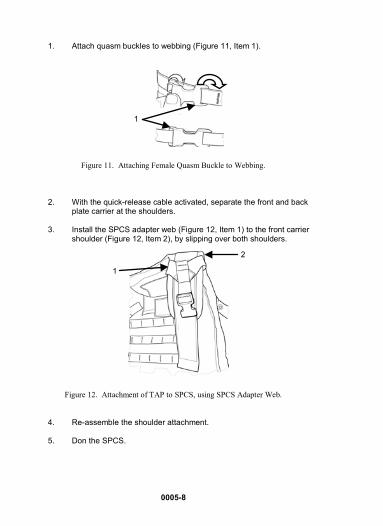
1. Attach quasm buckles to webbing (Figure 11, Item 1).
Figure 11. Attaching Female Quasm Buckle to Webbing.
2. With the quick-release cable activated, separate the front and back plate carrier at the shoulders.
3. Install the SPCS adapter web (Figure 12, Item 1) to the front carrier
shoulder (Figure 12, Item 2), by slipping over both shoulders.
Figure 12. Attachment of TAP to SPCS, using SPCS Adapter Web.
4. Re-assemble the shoulder attachment.
5. Don the SPCS.
2
1
1

0005-9/10 blank
6. Re-assemble the shoulder attachment.
7. Center the TAP on the front of the SPCS.
8. Use the male release buckles to secure the TAP to the female SPCS adapters (Figure 13, Item 1).
Figure 13. Attaching TAP to SPCS.
9. Secure the male side-release buckles to the female side-release buckles on each side of SPCS.
END OF TASK END OF WORK PACKAGE
1


0006 OPERATION UNDER USUAL CONDITIONS
POUCH/POCKET ATTACHMENT
0006-1/2 blank
INITIAL SETUP: Not Applicable POUCH/POCKET ATTACHMENT
CAUTION
Attachment system is extremely secure and stable when properly used. Failure to attach properly could lead to loss of or damage to equipment. Do not simply place the attaching strap through the vest webbing without also passing through pouch webbing. The pouches will not be secure if attached in this manner. Failure to attach properly could lead to loss of or damage to equipment.
1. To properly attach a pouch/pocket, choose the desired attachment point on the vest panel.
2. Line up the top of the pouch evenly with the top of the nearest
horizontal 1-inch webbing, that goes across the panels. 3. Insert the pouch attachment straps down the 1 1/2-inch channel and
then behind the 1-inch webbing on the back of the pouch.
4. Continue weaving the attaching straps (Figure 1, Item 1) behind the horizontal webbing (Figure 1, Item 2) on the vest and the webbing on the back of the pouch, until the pouch is secured along its entire length.
5. Secure snap fastener.
Figure 1. Correct (Left) and Incorrect (Right) Pouch/Pocket Attachment. END OF TASK END OF WORK PACKAGE
1
2


0007 OPERATION UNDER USUAL CONDITIONS CANTEEN/GENERAL PURPOSE POUCH
0007-1
INITIAL SETUP: Not Applicable CANTEEN/GENERAL PURPOSE POUCH
NOTE
The canteen/general purpose pouch has a variety of uses. It can be used as a carrier for the canteen or for various small items.
Canteen Pouch
1. Slide the top flap down inside the back of the pouch before inserting the canteen and cup.
2. Allow the V-shaped straps to pass over the neck of the canteen, and
fasten the buckle. END OF TASK
General Purpose Pouch This pouch is able to hold one stripped-down MRE, five M16 or M4 magazines, or AN/PVS-14 goggle insert, and various other items. The side pockets on the pouch are designed for carrying items such as first-aid dressings, water purification tablets, a compass, or other small equipment.
1. Pull the top flap out. 2. Insert the V-shaped strap under the webbing on the top flap; and
insert items, such as goggles, inside the pouch.

0007-2
3. Secure the plastic male and female buckle fasteners (Figure 1, Item 1) on front of the pouch.
Figure 1. Canteen/General Purpose Pouch. END OF TASK END OF WORK PACKAGE
1

0008 OPERATION UNDER USUAL CONDITIONS
LARGE AND MEDIUM SUSPENSION SYSTEMS
0008-1
INITIAL SETUP: Not Applicable
SUSPENSION SYSTEMS
The MOLLE II is made up of the Large Pack Assembly and Medium Pack Assembly Suspension System.
LARGE PACK ASSEMBLY
The large pack, large frame, shoulder straps, and hip belt make up the Large Pack Assembly. The other components are provided as needed.
Large Pack
The MOLLE II large pack capacity is 4000 cubic inches. The side sustainment pouch capacity is 500 cubic inches each. The top flap of the large pack (Figure 1) is a mesh pocket for small reference and information materials. It is secured with hook-and-loop closure.
Figure 1. Large Pack Assembly.

0008-2
Large Frame
The molded large frame is contoured to fit the shape of the back and allow the user to wear the rear ballistic plate of standard body armor without discomfort. The large frame front view (Figure 2, Item 1) and side view (Figure 2, Item 2) is shown below.
Figure 2. Large Frame.
Attaching Shoulder Strap Assembly to MOLLE II Large Pack Frame
NOTE
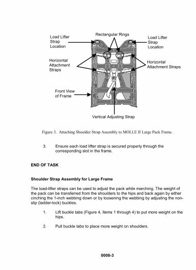
Ensure webbing is routed over and then under the two rectangular rings on the four horizontal straps.
Taller Soldiers (6 foot 2 inches and above) can move the shoulder strap assembly up on the frame assembly.
1. Secure and tighten four horizontal attachment straps.
2. Secure vertical adjustment strap.
1 2
0008-3
Figure 3. Attaching Shoulder Strap Assembly to MOLLE II Large Pack Frame.
3. Ensure each load lifter strap is secured properly through thecorresponding slot in the frame.
END OF TASK
Shoulder Strap Assembly for Large Frame
The load-lifter straps can be used to adjust the pack while marching. The weight of the pack can be transferred from the shoulders to the hips and back again by either cinching the 1-inch webbing down or by loosening the webbing by adjusting the non-slip (ladder-lock) buckles.
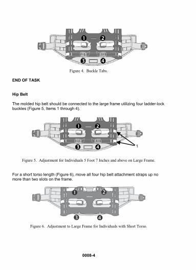
1. Lift buckle tabs (Figure 4, Items 1 through 4) to put more weight on the hips.
2. Pull buckle tabs to place more weight on shoulders.
Horizontal Attachment Straps
Load Lifter Strap Location
Horizontal Attachment Straps
Load Lifter Strap Location
Vertical Adjusting Strap
Rectangular Rings
Front View of Frame
0008-4
Figure 4. Buckle Tabs.
END OF TASK Hip Belt The molded hip belt should be connected to the large frame utilizing four ladder-lock buckles (Figure 5, Items 1 through 4).
Figure 5. Adjustment for Individuals 5 Foot 7 Inches and above on Large Frame.
For a short torso length (Figure 6), move all four hip belt attachment straps up no more than two slots on the frame.
Figure 6. Adjustment to Large Frame for Individuals with Short Torso.
1

0008-5
Proper use of hip belt (Figure 7, Item 1) allows the Soldier to distribute the weight of the pack on the hips, and proper position of the hip belt will cover the hip bone. Proper placement will reduce or eliminate the problem of “rucksack paralysis,” which is numbness in hands during prolonged wearing of pack.
Figure 7. Hip Belt Placement on Hips.
NOTE
Ensure the four horizontal attachment straps are tighten- ed as much as possible to eliminate slippage of straps and to ensure maximum comfort and security.
Keep frame centered on hip belt during attachment of horizontal straps, and keep centered until attachment is complete.
1. Secure four horizontal attachment straps (Figure 8, Item 1) through their corresponding slots (Figure 8, Item 2) on the frame (Figure 8, Item 3).
1

0008-6
Figure 8. Routing Straps through Frame.
2. Ensure free-running ends are routed back through horizontal bar on ladder-lock buckle to eliminate possible slippage of webbing and to ensure maximum tension is maintained.
3. Attach loop end of the 28-inch adjustor strap through slot that is centered, adjacent to hip belt.
4. Secure quick-release male buckle (Figure 9, Item 1) of 28-inch adjustor strap to female (Figure 9, Item 2) portion quick-release buckle on shoulder strap.
Figure 9. Quick-Release Buckle on Adjustor Strap.
5. Attach the adjustor strap on the other side.
1
2
3
2 1
0008-7
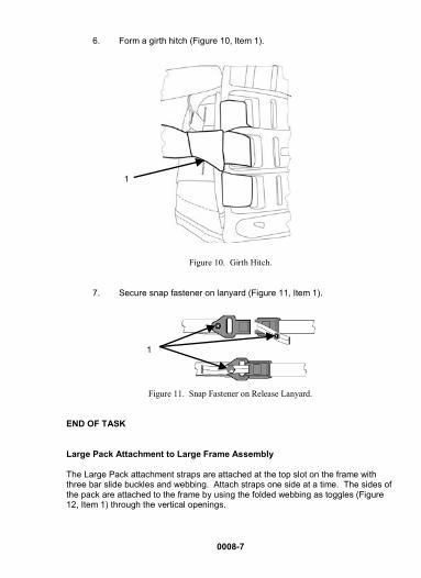
6. Form a girth hitch (Figure 10, Item 1).
Figure 10. Girth Hitch.
7. Secure snap fastener on lanyard (Figure 11, Item 1).
Figure 11. Snap Fastener on Release Lanyard.
END OF TASK
Large Pack Attachment to Large Frame Assembly
The Large Pack attachment straps are attached at the top slot on the frame with three bar slide buckles and webbing. Attach straps one side at a time. The sides of the pack are attached to the frame by using the folded webbing as toggles (Figure 12, Item 1) through the vertical openings.
1
1

0008-8
Figure 12. Folded Webbing as Toggles.
1. Place the large pack (Figure 13) face down on level surface.
2. Position frame assembly on top of pack.
3. Run the free-running end of strap (with 45° angle) through corresponding slot on frame, beginning with the top of pack and frame assembly.
4. Pass free-running end through the three bar slide buckles.
5. Secure free-running free end by passing strap back through the exposed bar on rear of buckle.
6. Tuck exposed, free-running end through the corresponding frame slot.
7. Remove male side-release buckle from side compression strap.
8. Pass side compression strap through corresponding slot in frame.
9. Reattach male side-release buckle to side compression strap.
10. Ensure the rolled securing tab is passed through corresponding slot on frame.
1

0008-9
Pocket Attachment Locations
Lower Compartment with Slide Fastener Access
11. Rolled portion must be passed completely through the slot, to ensure security.
12. Continue securing side compression straps (Figure 13) and rolled tabs down the side of the frame.
13. Repeat this process for opposite side.
Figure 13. Large Pack with Side Sustainment Pouches. END OF TASK
Pocket Attachment Locations
Main Compartment
Mesh Lid Pocket Side Sustainment Pouch
Side Compression Straps
Side Compression Straps
0008-10
MEDIUM PACK ASSEMBLY
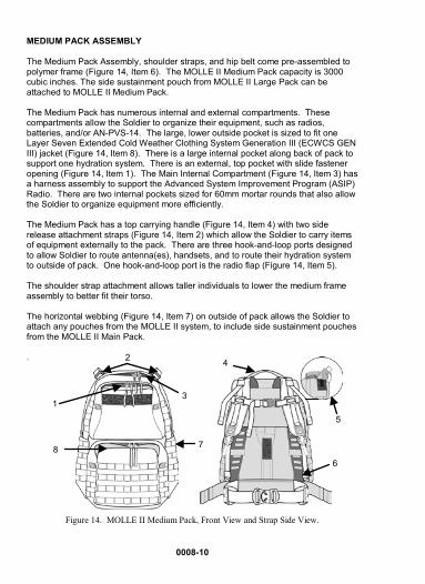
The Medium Pack Assembly, shoulder straps, and hip belt come pre-assembled to polymer frame (Figure 14, Item 6). The MOLLE II Medium Pack capacity is 3000 cubic inches. The side sustainment pouch from MOLLE II Large Pack can be attached to MOLLE II Medium Pack.
The Medium Pack has numerous internal and external compartments. These compartments allow the Soldier to organize their equipment, such as radios, batteries, and/or AN-PVS-14. The large, lower outside pocket is sized to fit one Layer Seven Extended Cold Weather Clothing System Generation III (ECWCS GEN III) jacket (Figure 14, Item 8). There is a large internal pocket along back of pack to support one hydration system. There is an external, top pocket with slide fastener opening (Figure 14, Item 1). The Main Internal Compartment (Figure 14, Item 3) has a harness assembly to support the Advanced System Improvement Program (ASIP) Radio. There are two internal pockets sized for 60mm mortar rounds that also allow the Soldier to organize equipment more efficiently.
The Medium Pack has a top carrying handle (Figure 14, Item 4) with two side release attachment straps (Figure 14, Item 2) which allow the Soldier to carry items of equipment externally to the pack. There are three hook-and-loop ports designed to allow Soldier to route antenna(es), handsets, and to route their hydration system to outside of pack. One hook-and-loop port is the radio flap (Figure 14, Item 5).
The shoulder strap attachment allows taller individuals to lower the medium frame assembly to better fit their torso.
The horizontal webbing (Figure 14, Item 7) on outside of pack allows the Soldier to attach any pouches from the MOLLE II system, to include side sustainment pouches from the MOLLE II Main Pack.
.
Figure 14. MOLLE II Medium Pack, Front View and Strap Side View.
2
5
2
1 3
8
4
6
7

0008-11
Donning of Large Pack and Medium Pack
WARNING
Components of the MOLLE II, once loaded for operation, may be heavy and require proper lifting technique in order to avoid injury.
1. Place pack on back by inserting arms through shoulder straps.
2. Buckle and adjust hip belt at proper location (Figure 15, Item 1),according to height.
3. Adjust shoulder strap buckles by pulling free-running webbing through quick-release buckle.
4. Adjust height of sternum strap to ensure maximum comfort and minimum interference with equipment, and secure free-running end.
5. Secure free-running ends of hip belt into tunnels.
Figure 15. Proper Position of Hip Belt.
END OF TASK
1

0008-12
Doffing of Large Pack and Medium Pack
WARNING
Components of the MOLLE II, once loaded for operation, may be heavy and require proper lifting technique in order to avoid injury.
Always disengage the hip belt buckle and chest/sternum strap before removing or activating quick-release on shoulder straps. Failure to follow this warning may lead to injury.
When in proximity to water, disengage hip belt buckle and chest/sternum strap to rapidly doff the large or medium pack. Failure to follow this warning may lead to injury.
Emergency Doffing
1. Disengage hip belt buckle and chest/sternum strap.
2. Pull upward on quick-release lanyards (Figure 16, Item 1) to disengage the buckle and let the pack fall away.
Figure 16. Quick-Release Lanyard.
END OF TASK
Prone Position Doffing
WARNING
Always disengage the hip belt buckle and chest/sternum strap before removing or activating quick-release on shoulder straps. Failure to follow this warning may lead to injury.
1. Disengage hip belt buckle and chest/sternum strap.
1

0008-13
2. Activate one of the shoulder strap quick releases, and let the pack fall off, by twisting to one side, when the hip belt and chest/sternum straps are also disengaged.
NOTE
Before resuming movement, re-secure quick-release buckle, hip belt buckle, and chest /sternum straps.
3. Re-attach the quick-release buckle (Figure 17, Item 1) by simply inserting the male portion (Figure 17, Item 2) into the female portion(Figure 17, Item 3).
Figure 17. Quick-Release Buckle.
4. Push male portion (Figure 18, Item 1) and female portion (Figure 18, Item 2) of the quick-release buckle until the latch tab (Figure 17, Item 4) clicks.
Figure 18. Connecting Quick-Release Buckle.
END OF TASK
1
2 3
4
1
2

0008-14
Side Sustainment Pouches
The large pack has two large, removable sustainment pouches (Figure 19, Item 1) which attach to the side of the MOLLE II main pack or medium pack, using the same interlocking attachment system as the FLC pockets. The side sustainment pouches each contain two D-rings on the sides, which allow them to be carried by the individual load-carrying universal sling (General Purpose Sling).
The sustainment pouches can also be added to the side of the assault pack to add 1000 cubic inches to its capacity. Front view and rear view (Figure 19, Item 2) are shown below.
Figure 19. Large Pack with Side Sustainment Pouches, Front and Rear View.
Attaching Side Sustainment Pouches to Main Pack
1. Disconnect the two top side compression straps before attaching side sustainment pouches.
2. Utilizing the MOLLE II attachment straps on back of pouch, weave four vertical attachment straps through corresponding slots (Figure 20, Item 3) on main pack front, starting with top-most webbing on side of pack. Do the same thing on the opposite side.
1 2
0008-15/16 blank
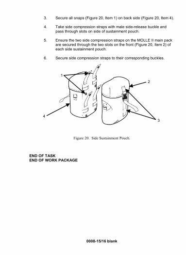
3. Secure all snaps (Figure 20, Item 1) on back side (Figure 20, Item 4).
4. Take side compression straps with male side-release buckle and pass through slots on side of sustainment pouch.
5. Ensure the two side compression straps on the MOLLE II main pack are secured through the two slots on the front (Figure 20, Item 2) of each side sustainment pouch.
6. Secure side compression straps to their corresponding buckles.
Figure 20. Side Sustainment Pouch.
END OF TASK END OF WORK PACKAGE
3
2 1
4


0009 OPERATION UNDER USUAL CONDITIONS
ASSAULT PACK
0009-1
INITIAL SETUP: Not Applicable ASSAULT PACK
The assault pack (Figure 1) has a total volume of 2000 cubic inches. The radio pouch can be attached to the internal compartment, rear panel of the assault pack, utilizing the 1-inch rectangular rings.
There are two white straps used for Airborne operations inside the assault pack. These straps can attach directly to the parachute harness D-rings. There is also an attachment loop if a lowering line is used.
Figure 1. Assault Pack, Front View.
Compression Strap
Attachment Strap to Frame
Front Pocket
Pocket Attachment Webbing
Carrying Handle

0009-2
Donning of Assault Pack
NOTE
Before resuming movement, be sure to re-secure quick- release buckle, waist belt buckle, and chest/sternum straps. Sternum strap can be slid up or down shoulder straps
for comfort.
1. Place the assault pack (Figure 2) on back by inserting arms through shoulder straps.
Figure 2. Assault Pack, Rear View.
2. Attach the quick-release buckle by simply inserting the male portion (Figure 3, Item 1) into the female portion (Figure 3, Item 2), and push until the latch tab (Figure 3, Item 3) clicks. Do not try to push down on the latch tab (Figure 3, Item 3).
Attachment Strap to Frame of MOLLE II Large
Sternum Strap
Quick-Release Buckle
Optional-Use Waist Belt
Shoulder Strap

0009-3
Figure 3. Quick-Release Buckle.
3. Secure snap fastener on lanyard (Figure 3, Item 4).
4. Adjust shoulder straps.
5. Adjust sternum strap height.
6. Stow free-running ends.
END OF TASK Emergency Doffing
WARNING
Always disengage the sternum strap and waist belt buckle before removing or activating quick-release on shoulder straps. Failure to follow this warning may lead to injury. When in proximity to water, disengage waist belt buckle and chest/sternum strap to rapidly doff the assault pack.
NOTE
Before resuming movement, re-secure quick-release buckle, waist belt buckle, and chest/sternum straps.
1. Disengage waist belt buckle and chest/sternum strap.
2. Pull upward on quick-release lanyards to disengage the buckle and let the pack fall away.
END OF TASK
1 2
3
4

0009-4
Prone Position Doffing
1. Disengage waist belt buckle and chest/sternum strap.
2. Activate one of the shoulder strap quick releases, and let the pack fall off, by twisting to one side, when the waist belt and chest/sternum straps are also disengaged.
3. Re-attach the quick-release buckle by simply inserting the male portion
(Figure 4, Item 1) into the female portion (Figure 4, Item 2), and push until the latch tab (Figure 4, Item 3) clicks. Do not try to push down on the latch tab (Figure 4, Item 3).
4. Secure snap fastener on lanyard (Figure 4, Item 4).
5. Unbuckle the waist belt.
6. Unbuckle the sternum strap.
7. Let the pack fall off the back.
Figure 4. Quick-Release Buckle.
END OF TASK END OF WORK PACKAGE
1
3
4
2
0010 OPERATION UNDER USUAL CONDITIONS
BANDOLEER
0010-1-2/blank
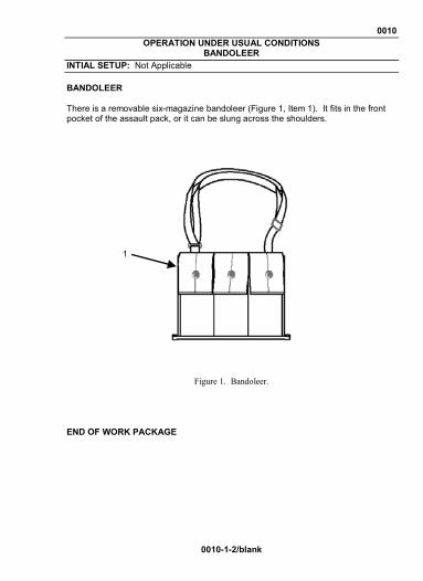
INTIAL SETUP: Not Applicable BANDOLEER There is a removable six-magazine bandoleer (Figure 1, Item 1). It fits in the front pocket of the assault pack, or it can be slung across the shoulders.
Figure 1. Bandoleer.
END OF WORK PACKAGE
1


0011 OPERATION UNDER USUAL CONDITIONS
WAIST PACK
0011-1
INITIAL SETUP: Not Applicable
WAIST PACK
NOTE
Ensure the attached hip belt is stowed into the tunnel on back of the waist pack when not used in the stand-
alone configuration.
The multi-purpose waist pack can be worn in one of three ways:
• Attached to the bottom of the assault pack by passing the male side-release buckles and webbing straps through the four webbing keepers on the bottom of the assault pack.
• Attached directly to the Fighting Load Carrier (FLC), or any MOLLE II pack system, by utilizing the stiffened webbing tabs, by weaving them into the corresponding slots on the back of the FLC.
• Carried in the stand-alone configuration by utilizing the attached 2-inch wide hip belt.
The illustration of the waist pack, on next page, shows the front view (Figure 1, Item 1) and rear view (Figure 1, Item 3), with the hip belt stowed into tunnels on back ofwaist pack (Figure 1, Item 2).

0011-2
The stand-alone method allows the user to rotate the waist pack around in front to easily access the contents of the pack, without removing the FLC or assault pack.
Figure 1. Waist Pack.
END OF WORK PACKAGE
3
1
2

0012 OPERATION UNDER USUAL CONDITIONS
MOLLE II LARGE FRAME
0012-1
INITIAL SETUP: Not Applicable
LARGE FRAME The molded large frame is contoured to fit the shape of the back and allow the user to wear the rear, ballistic plate of standard body armor without discomfort. The front view (Figure 1, Item 1) and side view (Figure 1, Item 2) are illustrated.
Figure 1. Large Frame.
Shoulder Strap Adjustment
WARNING
Proper attachment of the shoulder straps to the frame is extremely important to prevent an unstable load. Failure to follow this warning may lead to injury.
The shoulder strap suspension of the frame is adjusted by securing the 1-inch webbing around the frame in the appropriate location, using the double rectangular ring.
1 2

0012-2
The proper location is determined by donning the frame and fastening the hip belt buckle, while wearing the vest. Position the shoulder straps so there is complete contact with the shoulder. A properly positioned hip belt (Figure 2, Item 1) will cover the hip bone.
Figure 2. Proper Hip Belt Location.
1. Secure four horizontal straps (Figure 3, Items 1 and 2) in appropriate
location for individual torso length.
2. For short torsos, move the hip belt location on the frame. If more adjustment is needed, move the shoulder strap location on the frame.
3. Taller individuals, approximately 6 foot 2 inches and above, may move shoulder suspension up and secure to fit their longer torso by adjusting horizontal straps (Figure 3, Items 1 and 2).
1

0012-3/4 blank
4. Once the four 1-inch webbing straps are secured around the frame, hold the shoulder straps in place by securing the 1-inch vertical webbing strap (Figure 3, Item 3).
Figure 3. Adjusting Straps on Large Pack Frame.
5. Secure with corresponding buckle. END OF TASK END OF WORK PACKAGE
1
2
1
2
3


0013 OPERATION UNDER USUAL CONDITIONS
MOLLE II MEDIUM FRAME
0013-1
INITIAL SETUP: Not Applicable
MEDIUM FRAME The molded MOLLE II medium frame is contoured to fit the shape of the back and allow the user to wear the rear ballistic plate of standard body armor without discomfort. The front view (Figure 1, Item 1) and side view (Figure 1, Item 2) are illustrated.
Figure 1. Medium Frame, Front and Side View. Shoulder Strap Adjustment
WARNING
Proper attachment of the shoulder strap suspension to the frame is extremely important to prevent an unstable load. Failure to follow this warning may lead to injury.
The shoulder strap suspension of the frame is adjusted by securing the vertical strap, the 2-inch webbing (Figure 2, Item 1), around the medium frame, in the appropriate location, using the slide buckle.
1 2
0013-2
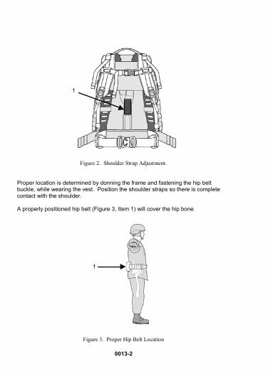
Figure 2. Shoulder Strap Adjustment. Proper location is determined by donning the frame and fastening the hip belt buckle, while wearing the vest. Position the shoulder straps so there is complete contact with the shoulder. A properly positioned hip belt (Figure 3, Item 1) will cover the hip bone.
Figure 3. Proper Hip Belt Location
1
1
0013-3/4 blank
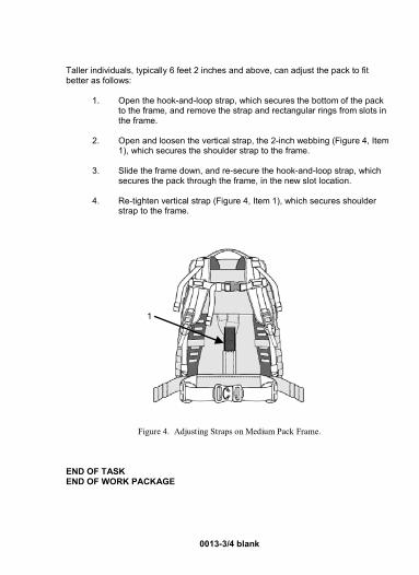
Taller individuals, typically 6 feet 2 inches and above, can adjust the pack to fit better as follows:
1. Open the hook-and-loop strap, which secures the bottom of the pack to the frame, and remove the strap and rectangular rings from slots in the frame.
2. Open and loosen the vertical strap, the 2-inch webbing (Figure 4, Item
1), which secures the shoulder strap to the frame.
3. Slide the frame down, and re-secure the hook-and-loop strap, which secures the pack through the frame, in the new slot location.
4. Re-tighten vertical strap (Figure 4, Item 1), which secures shoulder
strap to the frame.
Figure 4. Adjusting Straps on Medium Pack Frame. END OF TASK END OF WORK PACKAGE
1


0014 OPERATION UNDER USUAL CONDITIONS
RADIO POCKET
0014-1/2 blank
INITIAL SETUP: Not Applicable RADIO POCKET Inside the large pack, against the back panel, is a water-resistant, removable radio pocket (Figure 1, Item 1) designed to carry a SINCGARS/ASIP (Single-Channel Ground-Air Radio System/Advanced SINCGARS Improvement Program) radio. This removable pocket contains D-rings on each side to allow the radio to be carried by the general purpose sling when a pack is not needed. When the radio must be carried in the large pack, the radio pocket (Figure 1, Item 1) is secured to the four metal rectangular rings on the inside of the large pack, using the 1-inch webbing.
Figure 1. Radio Pocket.
END OF WORK PACKAGE
1


CHAPTER 3 – TROUBLESHOOTING PROCEDURES 0015 OPERATOR MAINTENANCE
TROUBLESHOOTING
0015-1/2 blank
INITIAL SETUP: Not Applicable GENERAL This work package is limited to the visual inspection of the equipment. The MOLLE II and its components are replaced at the Central Issue Facility (CIF) or in accordance with (IAW) Unit Standard Operating Procedure (SOP), if it is not serviceable.
Table 1. Troubleshooting Index.
END OF WORK PACKAGE
Symptom Procedure Frayed or Broken Straps Exchange at CIF/per unit SOP. Missing or Broken Buckles Exchange at CIF/per unit SOP, or
refer to WP 0017 in this TM to replace.
Broken Webbing Exchange at CIF/per unit SOP. Missing or Broken Snaps Exchange at CIF/per unit SOP. Damaged Pockets/Pouches Exchange at CIF/per unit SOP.


CHAPTER 4 – OPERATOR MAINTENANCE INSTRUCTIONS 0016 OPERATOR MAINTENANCE
MOLLE II AND HYDRATION SYSTEM INSPECT, CLEAN
0016-1
INITIAL SETUP: Not Applicable OPERATOR MAINTENANCE MOLLE II Inspect The MOLLE II should be inspected prior to and after each use. Place the MOLLE II components in an area favorable to perform a general visual inspection. Look for obvious tears, holes, missing parts, obvious dirt, or other damage. Complete the general inspection and note any deficiencies. Exchange missing or damaged components at the Central Issue Facility (CIF) or in accordance with (IAW) Unit Standard Operating Procedure (SOP). MOLLE II Cleaning
NOTE
Remember, extremely dirty or damaged equipment can eventually fail to perform its intended function. Exchange damaged equipment at your CIF or IAW Unit SOP.
1. Scrape dirt and dust from the item, using a brush that will not cut into the fabric.
2. Hose or wash the item in a pail of water, using mild detergent (WP
0021, Item 1) or soap.
3. Rinse thoroughly with clean water.
4. Dry the item in shade or indoors.
5. Turn in for repair or replacement.
END OF TASK

0016-2
MOLLE II Hydration System Inspect The MOLLE II comes with an on-the-move tube hydration system. This system is intended to supplement, not replace, the 1-quart canteen. There are two similar designs that are approved for use with the MOLLE II: Hydramax (Figure 1, Item 1) and Storm® (Figure 1, Item 2). There are four grimlock buckles (Figure 1, Item 3) to secure the Hydramax Hydration System directly to body armor or any webbing on MOLLE II pack system. NOTE
Remove the hydration system from body armor before wearing any MOLLE II pack system on back. Place the hydration system in or on the MOLLE II pack. Tighten and secure shoulder straps behind the carrier to eliminate any snag hazards.
.
Figure 1. Hydration Systems.
3
1 2
3

0016-3/4 blank
MOLLE II Hydration System Cleaning Clean hydration system before and after each use. Clean the hydration system as described below:
NOTE
• Do not use chlorine bleach on any of the textile com-
ponents of the hydration system.
• Do not use yellow soap, cleaning fluids, or solvents that will discolor or deteriorate the item.
• Do not launder or dry item in fixed-field, commercial, or
home-type laundry equipment.
• Do not attempt to dye.
• Do not dry in direct sunlight, direct heat, or open flame.
• Beverage-based powders should not be used in your hydration system.
• Be sure the cap is screwed all the way down to prevent leaking. If the cap leaks, make sure the cap lanyard is pushed down past the screw threads; otherwise, the lanyard could prevent the cap from completely closing.
• The use of liquids other than water will accelerate mold growth and will require more frequent cleaning. 1. Wash hydration system with small amount of mild soap and hot water
before and after each use. 2. Rinse thoroughly with clean water to eliminate any residual soap. END OF TASK END OF WORK PACKAGE


0017 OPERATOR MAINTENANCE
MOLLE II BUCKLES INSPECT, REPLACE
0017-1
INITIAL SETUP: Not Applicable OPERATOR MAINTENANCE Inspect The MOLLE II should be inspected prior to and after each use. Place the MOLLE II components in an area favorable to perform a general visual inspection. Look for any damaged or broken buckles. Complete the general inspection and note any deficiencies. Exchange missing or damaged components at the Central Issue Facility (CIF) or repair following instructions in this Work Package (WP). Replacement of Male or Female Portion Non-Adjustable Side-Release Buckle
NOTE Remove all excess buckle parts from webbing before replacement. Do not cut webbing to replace buckle.
1. Remove damaged or broken buckle.
2. Insert webbing through center slot of new male or female portion
buckle.
3. Insert remainder of webbing, and push into buckle.
END OF TASK Replacement of Male or Female Portion Adjustable Buckle
1. Remove damaged or broken buckle.
2. Take free-running end and pass through upper slot of new buckle.

0017-2
3. Continue to pass free-running end through lower slot to complete attachment.
END OF TASK
Replacement of Grimlocks Grimlocks may be found on Hydramax hydration system and on Fighting Load Carrier (FLC). The use of grimlocks allows the Soldier to fasten the hydration system directly to their body armor or MOLLE II webbing.
1. Insert plunger assembly (Figure 1, Item 1) through webbing loop.
2. Ensure edge of webbing passes under large slotted portion on grimlock main body.
3. Continue to feed webbing until fully secured, under both edges of slot,
on main body.
Figure 1. Grimlock.
END OF TASK
1

0017-3/4 blank
Replacement of Quasm Buckle
NOTE
The quasm buckle (female portion, non-adjustable) allows rapid attachment of Tactical Assault Panel (TAP) to Improved Outer Tactical Vest (IOTV) and Soldier Plate Carrier System (SPCS).
1. Remove broken buckle(s) if still attached.
2. Attach quasm buckle (Figure 2, Item 1) (female portion, non-
adjustable) to cummerbund of IOTV center row of horizontal webbing or to side plate carrier side panel.
3. Face open end of buckle forward, towards front of body armor.
4. Insert webbing through forward end of buckle.
5. Attach quasm female portion to TAP male portion.
6. Repeat steps 1 through 4 for placing quasm buckle on other side.
Figure 2. Quasm Buckle.
END OF TASK END OF WORK PACKAGE
1


CHAPTER 5 – SUPPORTING INFORMATION 0018 REFERENCES
0018-1/2 blank
GENERAL This work package lists related Army Regulations, DA Pamphlets, Field Manuals, DA Forms, and miscellaneous publications referenced in this manual. Army Regulations AR 700-138
Army Logistics Readiness and Sustainability
DA Pamphlets DA PAM 25-33
User’s Guide for Army Publications and Forms
DA PAM 750-8
The Army Maintenance Management System (TAMMS) Users Manual
DA PAM 738-751
Functional Users Manual for the Army Maintenance Systems – Aviation (TAMMS-A)
Field Manuals FM 4-25.11
First Aid Information
FM 3-11.5
Multiservice Tactics, Techniques, and Procedures for Chemical, Biological, Radiological, and Nuclear Decontamination
Forms DA Form 12-R
Request for Establishment of a Publications Account
DA Form 2028
Recommended Changes to Publications and Blank Forms
SF 368
Product Quality Deficiency Report
END OF WORK PACKAGE


0019 COMPONENTS OF END ITEM (COEI) AND BASIC ISSUE ITEMS (BII) LISTS
0019-1
INTRODUCTION
Scope
This work package lists COEI and BII for the MOLLE II to help you inventory items for safe and efficient operation of the equipment.
General
The COEI and BII information is divided into the following lists:
Components of End Item (COEI). This list is for information purposes only and is not authority to requisition replacements. These items are part of the MOLLE II. As part of the end item, these items must be with the end item whenever it is issued or transferred between property accounts. Items of COEI are removed and separately packaged for transportation or shipment only when necessary. Illustrations are furnished to help you find and identify the items.
Basic Issue Items (BII). These essential items are required to place the MOLLE II in operation, operate it, and to do emergency repairs. Although shipped separately packaged, BII must be with the MOLLE II during operation and when it is transferred between property accounts. Listing these items is your authority to request/requisition them for replacement based on authorization of the end item by the Table of Organization (TOE/MTOE). Illustrations are furnished to help you find and identify the items.
Explanation of Columns in the COEI List and BII List
Column (1) Item Number. Gives you the reference number of the item listed.
Column (2) National Stock Number (NSN). Identifies the stock number of the item to be used for requisitioning purposes.
Column (3) Description, Part Number/(CAGEC). Identifies the Federal item name (in all capital letters) followed by a minimum description when needed. The stowage location of COEI and BII is also included in this column. The last line below the description is the CAGEC (Commercial and Government Entity Code (CAGEC) (in parentheses) and the part number.
Column (4) Usable On Code. When applicable, gives you a code if the item you need is not the same for different models of equipment.
Column (5) U/I. Unit of Issue (U/I). Indicates the physical measurement or count of the item as issued per the National Stock Number shown in column (2).
Column (6) Qty Rqr. Indicates the quantity required.

1
2 through 29
3
2
4
0019-2

Table 1. Components of End Item (COEI) List for MOLLE II.
(1) Item
Number
(2) National Stock Number (NSN)
(3) Description, Part Number/(CAGEC)
(4) Usable
on Code
(5) U/I
(6) Qty Rqr
1
2
3
4
8465-01-583-6442 8465-01-580-0481 8465-01-583-6329 8465-01-580-0689 8465-01-592-7687 8465-01-590-1340 8465-01-592-7691 8465-01-590-1345
RIFLEMAN, SET, TACTICAL ASSAULT PANEL, CO/PD-02-02/(3T951) CO/PD-02-02/(3T951) TACTICAL ASSAULT PANEL (TAP), ASSEMBLY, CO/PD-02-02/(3T951) CO/PD-02-02/(3T951) HARNESS ASSEMBLY, CO/PD-02-02/(81337) CO/PD-02-02/(3T951) ADAPTER, RIGHT SHOULDER, CO/PD-02-02/(81337) CO/PD-02-02/(81337)
UCP OCP
UCP OCP
UCP OCP
UCP OCP
EA
EA EA
EA
1
1
1
1
0019-3

7A
9 through 29
7B
6
8
5
0019-4

Table 1. Components of End Item (COEI) List for MOLLE II – Continued.
(1) Item
Number
(2) National Stock Number (NSN)
(3) Description, Part Number/(CAGEC)
(4) Usable
on Code
(5) U/I
(6) Qty Rqr
5
6
7A
7B
8
8465-01-592-7693 8465-01-590-1361 8465-01-592-7695 8465-01-590-1363 8465-01-600-8167 8465-01-600-8170 8315-01-603-0306 8465-01-525-0578 8465-01-580-0477
RIFLEMAN, SET, TACTICAL ASSAULT PANEL – Continued ADAPTER, LEFT SHOULDER, CO/PD-02-02/(81337) CO/PD-02-02/(81337) ADAPTER, PLATE CARRIER, CO/PD-02-02/(81337) CO/PD-02-02/(3T951) BUCKLE, TACTICAL ASSAULT PANEL, 810-1076/(02768) 810-1076/(02768) BUCKLE, (Female/Quasm) 810-1076-5679/(1YWB4) RIFLEMAN SET (with FLC), MIL-C-44107/(81349) CO/PD-02-02/(3T951)
UCP OCP
UCP OCP
UCP OCP
UCP OCP
EA
EA
EA
1
2
1
0019-5

10 through 14
9 10
11 12
0019-6

Table 1. Components of End Item (COEI) List for MOLLE II – Continued.
0019-7
(1) Item
Number
(2) National Stock Number (NSN)
(3) Description, Part Number/(CAGEC)
(4) Usable
on Code
(5) U/I
(6) Qty Rqr
9
10
11
12
8465-01-525-0575 8465-01-580-0591 8465-01-525-0577 8465-01-580-0573 8465-01-525-0585 8465-01-580-0693 8465-01-525-0589 8465-01-580-0697
RIFLEMAN SET (with FLC) – Continued SET, FIGHTING LOAD CARRIER, CO/PD-02-02/(3T951) CO/PD-02-02/(3T951) FIGHTING LOAD CARRIER, CO/PD-02-02/(3T951) CO/PD-02-02/(3T951) POUCH, CANTEEN, GENERAL PURPOSE, CO/PD-02-02/(3T951) CO/PD-02-02/(3T951) POUCH, HAND GRENADE, CO/PD-02-02/(3T951) CO/PD-02-02/(3T951)
UCP OCP
UCP OCP
UCP OCP
UCP OCP
EA
EA
EA
1
2
2

13 14
15
16
0019-8

Table 1. Components of End Item (COEI) List for MOLLE II – Continued.
0019-9
(1) Item
Number
(2) National Stock Number (NSN)
(3) Description, Part Number/(CAGEC)
(4) Usable
on Code
(5) U/I
(6) Qty Rqr
13
14
15
16
8465-01-525-0606 8465-01-580-0701 8465-01-525-0598 8465-01-580-0967 8465-01-524-5250 8465-01-580-0981 8465-01-524-7263 8465-01-580-1300
RIFLEMAN SET (with FLC) – Continued POUCH, M4 TWO MAGAZINE, CO/PD-02-02/(3T951) CO/PD-02-02/(3T951) POUCH, M4 THREE MAGAZINE, CO/PD-02-02/(3T951) CO/PD-02-02/(3T951) ASSAULT PACK, CO/PD-02-02/(3T951) CO/PD-02-02/(3T951) WAIST PACK, CO/PD-02-02/(3T951) CO/PD-02-02/(3T951)
UCP OCP
(UCP (OCP
UCP OCP
UCP OCP
EA
EA
EA
EA
3
2
1
1
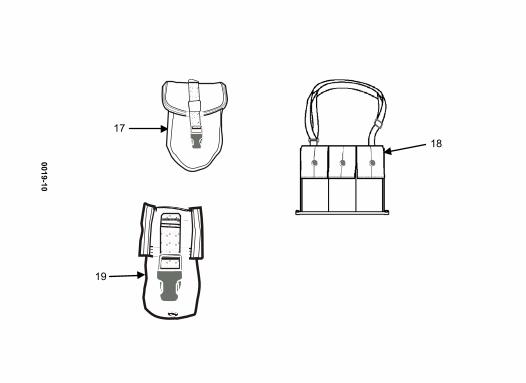
17 18
19
0019-10

Table 1. Components of End Item (COEI) List for MOLLE II – Continued.
(1) Item
Number
(2) National Stock Number (NSN)
(3) Description, Part Number/(CAGEC)
(4) Usable
on Code
(5) U/I
(6) Qty Rqr
17
18
19
8465-01-524-8407 8465-01-580-1303 8465-01-524-7309 8465-01-580-1312 8465-01-524-7324 8465-01-580-1313
RIFLEMAN SET (with FLC) – Continued CARRIER, ENTRENCHING TOOL, CO/PD-02-02/(3T951) CO/PD-02-02/(3T951) BANDOLEER AMMUNITION POUCHES, CO/PD-02-02/(3T951) CO/PD-02-02/(3T951) POUCH, FLASH BANG GRENADE, CO/PD-02-02/(3T951) CO/PD-02-02/(3T951)
UCP OCP
UCP OCP
UCP OCP
EA
EA
EA
1
1
1
0019-11

23
21 through 24
20 21
22
24
100 OZ.
0019-12

Table 1. Components of End Item (COEI) List for MOLLE II – Continued.
(1) Item
Number
(2) National Stock Number (NSN)
(3) Description, Part Number/(CAGEC)
(4) Usable
on Code
(5) U/I
(6) Qty Rqr
20
21
22
23
24
8465-01-525-5531 8465-01-580-1316 8465-01-524-8362 8465-01-580-1319 8465-01-519-2304 8465-01-519-2385 8465-01-519-2383
RIFLEMAN SET (with FLC) – Continued
HYDRATION SYSTEM, (Hydramax) CO/PD-02-02/(3T951) CO/PD-02-02/(3T951) CARRIER, HYDRATION, CO/PD-02-02/(3T951) CO/PD-02-02/(3T951) BLADDER, HYDRATION SYSTEM, CO/PD-02-02/(1A863) DRINK TUBE, HYDRATION SYSTEM, CO/PD-02-02/(1A863) BITE VALVE, HYDRATION SYSTEM, CO/PD-02-02/(1A863)
UCP OCP
UCP OCP
EA
EA
1
1
0019-13

26 through 29
26
27
25
26
28
0019-14
29

Table 1. Components of End Item (COEI) List for MOLLE II – Continued.
(1) Item
Number
(2) National Stock Number (NSN)
(3) Description, Part Number/(CAGEC)
(4) Usable
on Code
(5) U/I
(6) Qty Rqr
25
26
27
28
29
8465-01-524-8396 8465-01-580-1317 8465-01-524-5232 8465-01-580-1537 8465-01-465-2096 8465-01-472-5106 8465-01-499-9948
RIFLEMAN SET (with FLC) – Continued
OR HYDRATION SYSTEM, (Camelbak Storm®) CO/PD-02-02/(3T951) CO/PD-02-02/(3T951) CARRIER HYDRATION SYSTEM, CO/PD-02-02/(3T951) CO/PD-02-02/(3T951) BLADDER, HYDRATION SYSTEM, R00475/(3T951) VALVE, DRINKING SYSTEM, 9410/(063G3) CONVERSION KIT, HYDRATION SYSTEM, 90512/(063G3)
UCP OCP
UCP OCP
EA
EA
1
1
0019-15

31 through 37
30
31
33
34
0019-16
32

Table 1. Components of End Item (COEI) List for MOLLE II – Continued.
(1) Item
Number
(2) National Stock Number (NSN)
(3) Description, Part Number/(CAGEC)
(4) Usable
on Code
(5) U/I
(6) Qty Rqr
30
31
32
33
34
8465-01-523-6276 8465-01-580-1556 8465-01-524-5285 8465-01-580-1560 8465-01-524-7226 8465-01-580-1563 8465-01-524-8368 8465-01-519-6440 8465-01-524-7232 8465-01-580-1575
FIELD PACK, LARGE, SET, CO/PD-02-02/(3T951) CO/PD-02-02/(3T951) RUCKSACK LARGE FIELD PACK, CO/PD-02-02/(3T951) CO/PD-02-02/(3T951) SUSTAINMENT POUCH, CO/PD-02-02/(3T951) CO/PD-02-02/(3T951) FRAME, (Large) CO/PD-02-02/(3T951) 1603/(55650) MOLDED WAIST BELT, CO/PD-02-02/(3T951) CO/PD-02-02/(3T951)
UCP OCP
UCP OCP
UCP OCP
UCP OCP
UCP OCP
EA
EA
EA
EA
1
1
1
1
0019-17

36
36
39 through 42
37 35
38 39
0019-18

0019-19
Table 1. Components of End Item (COEI) List for MOLLE II – Continued.
(1) Item
Number
(2) National Stock Number (NSN)
(3) Description, Part Number/(CAGEC)
(4) Usable
on Code
(5) U/I
(6) Qty Rqr
35
36
37
38
39
8465-01-524-7240 8465-01-580-1664 8465-01-524-7241 8465-01-580-1666 8465-01-524-8415 8465-01-580-1672 8465-01-592-7700 8465-01-585-1512 8465-01-592-7850 8465-01-585-1512
FIELD PACK, LARGE, SET – Continued ENHANCED FRAME SHOULDER STRAPS, CO/PD-02-02/(3T951) CO/PD-02-02/(3T951) LOAD LIFTER ATTACHMENT STRAP, CO/PD-02-02/(3T951) CO/PD-02-02/(3T951) BUCKLE, MALE SHOULDER SUSPENSION, CO/PD-02-02/(3T951) CO/PD-02-02/(3T951) RUCKSACK SET, (Medium) CO/PD-02-02/(81337) CO/PD-02-02/(3T951) PACK, RUCKSACK, (Medium) CO/PD-02-02/(81337) CO/PD-02-02/(3T951)
UCP OCP
UCP OCP
UCP OCP
UCP OCP
UCP OCP
EA
EA
EA
EA
1
2
2
1

44 through 45
43
42
41
40
44
0019-20

Table 1. Components of End Item (COEI) List for MOLLE II – Continued.
(1) Item
Number
(2) National Stock Number (NSN)
(3) Description, Part Number/(CAGEC)
(4) Usable
on Code
(5) U/I
(6) Qty Rqr
40
41
42
43
44
8465-01-592-7708 8465-01-590-1377 8465-01-592-7702 8465-01-590-1369 8465-01-592-7706 8465-01-590-1372 8465-01-524-7328 8465-01-580-1680 8465-01-524-7345 8465-01-580-2582
RUCKSACK SET, (Medium) – Continued BELT WAIST, RUCKSACK, CO/PD-02-02/(81337) CO/PD-02-02/(3T951) SHOULDER STRAP, RUCKSACK, CO/PD-02-02/(81337) CO/PD-02-02/(3T951) FRAME, RUCKSACK, CO/PD-02-02/(81337) CO/PD-02-02/(3T951) CARRIER, PISTOL HOLSTER, (with FLC or TAP) (Pistolman Set) CO/PD-02-02/(3T951) CO/PD-02-02/(3T951) HOLSTER LEG EXTENDER, CO/PD-02-02/(3T951) CO/PD-02-02/(3T951)
UCP OCP
UCP OCP
UCP OCP
UCP OCP
UCP OCP
EA
EA
EA
EA
1
1
1
1
0019-21
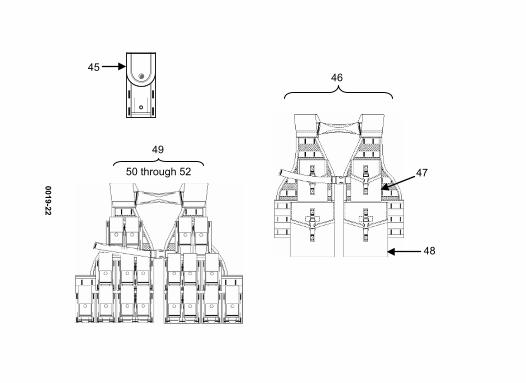
50 through 52
49
48
45 46
0019-22
47

Table 1. Components of End Item (COEI) List for MOLLE II – Continued.
(1) Item
Number
(2) National Stock Number (NSN)
(3) Description, Part Number/(CAGEC)
(4) Usable
on Code
(5) U/I
(6) Qty Rqr
45
46
47
48
49
8465-01-524-7361 8465-01-580-2610 8465-01-524-7362 8465-01-580-2618 8465-01-524-7365 8465-01-580-2621 8465-01-524-7620 8465-01-580-2628 8465-01-524-7624 8465-01-580-2743
CARRIER, PISTOL HOLSTER, (with FLC or TAP) (Pistolman Set) – Continued POCKET, AMMUNITION MAGAZINE, (9mm Magazine Pouch (Single)) CO/PD-02-02/(3T951) CO/PD-02-02/(3T951) SAW GUNNER SET, CO/PD-02-02/(3T951) CO/PD-02-02/(3T951) POCKET, AMMUNITION MAGAZINE, (100-Round Utility Pouch) CO/PD-02-02/(3T951) CO/PD-02-02/(3T951) POCKET, AMMUNITION MAGAZINE, (200-Round Saw Gunner Pouch) CO/PD-02-02/(3T951) CO/PD-02-02/(3T951) GRENADIER SET, CO/PD-02-02/(3T951) CO/PD-02-02/(3T851)
UCP OCP
UCP OCP
UCP OCP
UCP OCP
UCP OCP
EA
EA
EA
4
2
2
0019-23

0019-24
50
51
52
53 54
54 through 57

Table 1. Components of End Item (COEI) List for MOLLE II – Continued.
(1) Item
Number
(2) National Stock Number (NSN)
(3) Description, Part Number/(CAGEC)
(4) Usable
on Code
(5) U/I
(6) Qty Rqr
50
51
52
53
54
8465-01-524-7625 8465-01-580-2756 8465-01-524-7628 8465-01-580-2763 8465-01-524-7636 8465-01-580-2768 8465-01-524-7632 8465-01-580-2774 8465-01-524-7635 8465-01-580-2779
GRENADIER SET – Continued POCKET, EXPLOSIVES, (40mm High Explosive Pouch (Single)) CO/PD-02-02/(3T951) CO/PD-02-02/(3T951) POCKET, EXPLOSIVES, (40mm High Explosive Pouch (Double)) CO/PD-02-02/(3T951) CO/PD-02-02/(3T951) POCKET, EXPLOSIVES, (40mm Pyrotechnic Pouch (Double)) CO/PD-02-02/(3T951) CO/PD-02-02/(3T951) MEDIC SET CO/PD-02-02/(3T951) CO/PD-02-02/(3T951) MEDIC BAG CO/PD-02-02/(3T951) CO/PD-02-02/(3T851)
UCP OCP
UCP OCP
UCP OCP
UCP OCP
UCP OCP
EA
EA
EA
EA
10
4
2
1
0019-25

0019-26
55
56
57

Table 1. Components of End Item (COEI) List for MOLLE II – Continued.
(1) Item
Number
(2) National Stock Number (NSN)
(3) Description, Part Number/(CAGEC)
(4) Usable
On Code
(5) U/I
(6) Qty Rqr
55
56
57
8465-01-524-7638 8465-01-580-2781 8465-01-524-7640 8465-01-580-2783 8465-01-524-7683 8465-01-580-2792
MEDIC SET – Continued EXTERNAL MEDICAL MODULAR POCKET CO/PD-02-02/(3T951) CO/PD-02-02/(3T951) BAG MEDICAL I.V. BANDOLEER CO/PD-02-02/(3T951) CO/PD-02-02/(3T951) PANEL MEDICAL BAG CO/PD-02-02/(3T951) CO/PD-02-02/(3T951)
UCP OCP
UCP OCP
UCP OCP
EA
EA
EA
8
1
1
0019-27

0019-28
Table 2. Basic Issue Items (BII) List for MOLLE II.
END OF WORK PACKAGE
(1)
Item Number
(2)
National Stock
Number (NSN)
(3) Description, Part Number/(CAGEC)
(4)
Usable On Code
(5)
U/I
(6)
Qty Recm
1
N/A TM 10-8465-236-10 EA 1
1

0020 ADDITIONAL AUTHORIZATION LIST
0020-1
INTRODUCTION SCOPE This work package lists additional items you are authorized for the support of the MOLLE II. GENERAL This list identifies items that do not have to accompany the MOLLE II and that do not have to be turned in with it. These items are all authorized to you by CTA, MTOE, TDA, or JTA. Explanation of Columns in the AAL Column (1) National Stock Number (NSN). Identifies the stock number of the item to be used for requisitioning purposes. Column (2) Description, Part Number/(CAGEC). Identifies the Federal item name (in all capital letters) followed by a minimum description when needed. The last line below the description is the part number and the Commercial and Government Entity Code (CAGEC) (in parentheses). Column (3) Usable On Code. When applicable, gives you a code if the item you need is not the same for different models of equipment. Column (4) U/I. Unit of Issue (U/I) indicates the physical measurement or count of the item as issued per the National Stock Number shown in column (1). Column (5) Qty Recm. Indicates the quantity recommended. Code Used on UCP MOLLE II OCP MOLLE II

0020-2
Table 1. Additional Authorization List. (1)
National Stock Number (NSN)
(2) Description, Part Number/(CAGEC)
(3) Usable
On Code
(4) U/I
(5) Qty
Recm.
8465-01-524-7253 8465-01-585-1552
ALICE CLIP ADAPTER, CO/PD-02-02/(3T951)
UCP OCP
8465-01-524-7694 8465-01-585-1344
BAG, AMMUNITION, (300-round 7.62 Ammo Bag), CO/PD-02-02/(3T951)
UCP OCP
8465-01-524-7639 8465-01-585-1540
BUCKLE SET, CO/PD-02-02/(3T951)
UCP OCP
8465-01-538-1868
8465-01-585-1687
FLAP, FIELD PACK, (Large Ruck Flap), CO/PD 05-3/(81337) CO/PD-02-02/(3T951)
UCP
OCP
8465-01-538-1647
8465-01-585-1373
FLAP, POUCH FIELD PACK, (Leaders Pocket Insert (Writing Instrument) Universal), CO/PD-02-02/(81337) LEADERS POCKET INSERT, (WRITING INSTRUMENT), CO/PD-02-02/(3T951)
UCP
OCP
8465-01-524-7246 8465-01-585-1545
K-BAR ADAPTER, CO/PD-02-02/(3T951)
UCP OCP
8465-01-524-7689 8465-01-585-1555
LASHING STRAPS, CO/PD-02-02/(3T951)
UCP OCP
8465-01-524-7692 8465-01-585-1299
MBITR POUCH, CO/PD-02-02/(3T951)
UCP OCP

0020-3
Table 1. Additional Authorization List – Continued.
(1) National Stock Number (NSN)
(2) Description, Part Number/(CAGEC)
(3) Usable
On Code
(4) U/I
(5) Qty
Recm.
8465-01-538-1497
8465-01-585-1362
PANEL, VEHICLE MOLLE, CO/PD 05-03/(81337) CO/PD-02-02/(3T951)
UCP
OCP
8465-01-538-2040
8465-01-585-1501
POUCH, ADMIN MOLLE, 8465-00-NSH-0614/(7P200) CO/PD-02-02/(3T951)
UCP
OCP
8465-01-538-1507
8465-01-585-1372
POUCH INSERT GPS MOLLE, CO/PD 05-03/(81337) CO/PD-02-02/(3T951)
UCP
OCP
8465-01-538-1523
8465-01-585-1371
POUCH, LEADER SET MOLLE, CO/PD 05-03/(81337) CO/PD-02-02/(3T951)
UCP
OCP
8465-01-538-1514
8465-01-585-1370
POUCH, PVS-14 MOLLE, CO/PD 05-03/(81337) CO/PD-02-02/(3T951)
UCP
OCP
8465-01-524-7684 8465-01-585-2132
RADIO POUCH, CO/PD-02-02/(3T951)
UCP OCP
8465-01-524-7691 8465-01-585-1296
SHOTGUN SHELL POUCH, CO/PD-02-02/(3T951)
UCP OCP

0020-4
Table 1. Additional Authorization List – Continued.
END OF WORK PACKAGE
(1) National Stock Number (NSN)
(2) Description, Part Number/(CAGEC)
(3) Usable
On Code
(4) U/I
(5) Qty
Recm.
8465-01-545-3444
8465-01-585-1346
SLING, UNIVERSAL, INDIVIDUAL LOAD, 2-6-0493/(81337) CO/PD-02-02/(3T951)
UCP
OCP
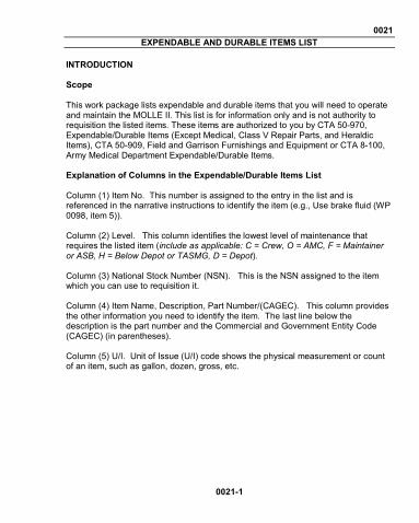
0021 EXPENDABLE AND DURABLE ITEMS LIST
0021-1
INTRODUCTION Scope This work package lists expendable and durable items that you will need to operate and maintain the MOLLE II. This list is for information only and is not authority to requisition the listed items. These items are authorized to you by CTA 50-970, Expendable/Durable Items (Except Medical, Class V Repair Parts, and Heraldic Items), CTA 50-909, Field and Garrison Furnishings and Equipment or CTA 8-100, Army Medical Department Expendable/Durable Items. Explanation of Columns in the Expendable/Durable Items List Column (1) Item No. This number is assigned to the entry in the list and is referenced in the narrative instructions to identify the item (e.g., Use brake fluid (WP 0098, item 5)). Column (2) Level. This column identifies the lowest level of maintenance that requires the listed item (include as applicable: C = Crew, O = AMC, F = Maintainer or ASB, H = Below Depot or TASMG, D = Depot). Column (3) National Stock Number (NSN). This is the NSN assigned to the item which you can use to requisition it. Column (4) Item Name, Description, Part Number/(CAGEC). This column provides the other information you need to identify the item. The last line below the description is the part number and the Commercial and Government Entity Code (CAGEC) (in parentheses). Column (5) U/I. Unit of Issue (U/I) code shows the physical measurement or count of an item, such as gallon, dozen, gross, etc.

0021-2
Table 1. Expendable and Durable Items List.
(1)
Item No.
(2) Level
(3) National Stock Number (NSN)
(4) Item Name, Description,
Part Number/ (CAGEC)
(5) U/I
1 C 7930-00-531-9715 Detergent, General Purpose TY2, MIL-D-16791 GL/(81349)
BT
END OF WORK PACKAGE

TM 10-8465-236-10
By Order of the Secretary of the Army:
RAYMOND T. ODIERNO General, United States Army
Chief of Staff
Official:
GERALD B. OKEEFE Acting Administrative Assistant
to the Secretary of the Army 1314219
Distribution: To be distributed in accordance with Initial Distribution Number 256908 requirements for TM 10-8465-236-10.


TM 10-8465-236-10
PIN: 086006-000