tm dynamic g90 - pride mobility g90 controller note: these instructions are compiled from the...
TRANSCRIPT
Synergy TRU-Balance BASIC OPERATION INSTRUCTIONS
ACN# 088 609 661
TM
Dynamic G90Controller

Dynamic G90 Controller www.pridemobility.com
NOTE: These instructions are compiled from the latest specifications andproduct information available at the time of publication. We reserve theright to make changes as they become necessary. Any changes to ourproducts may cause slight variations between the illustrations and expla-nations in this manual and the product you have purchased. The latest/current version of this manual is available on our website.
Copyright © 2009Pride Mobility Products CorporationINFMANU3721/Rev B/April 2009
WARNING! An authorized Pride Provider or a qualifiedtechnician must perform the initial setup of this productand must perform all of the instructions in this manual.
The symbols below are used throughout this owner's manual and on thecontroller to identify warnings and important information. It is very impor-tant for you to read them and understand them completely.
WARNING! Indicates a potentially hazardous condition/situation. Failure to follow designated procedures cancause either personal injury, component damage, ormalfunction. On the product, this icon is represented as ablack symbol on a yellow triangle with a black border.
MANDATORY! These actions should be performed asspecified. Failure to perform mandatory actions can causepersonal injury and/or equipment damage. On the product,this icon is represented as a white symbol on a blue dotwith a white border.
PROHIBITED! These actions are prohibited. These actionsshould not be performed at any time or in anycircumstances. Performing a prohibited action can causepersonal injury and/or equipment damage. On the product,this icon is represented as a black symbol with a red circleand a red slash.
SAFETY GUIDELINES
www.pridemobility.com Dynamic G90 Controller
LABEL INFORMATION ................................................................... 4
INTRODUCTION ................................................................................ 5
DYNAMIC G90 CONTROLLER .................................................... 7
PRECAUTIONARY GUIDELINES ............................................... 7
OPERATING THE DYNAMIC G90 CONTROLLER ............ 11
CONTROLLER COMMUNICATIONS CONNECTOR ......... 15
OFF-BOARD CHARGER SOCKET ............................................ 15
POWER ACCESSORY CONTROL ............................................. 15
BATTERY SAVER FEATURE ...................................................... 15
SLEEP MODE ..................................................................................... 16
OUT OF NEUTRAL AT POWER UP (OONAPU) .................. 16
ERROR CODES ................................................................................. 16
CARE AND MAINTENANCE ........................................................ 18
WARRANTY ....................................................................................... 18
TABLE OF CONTENTS

PRODUCT SAFETY SYMBOLSThe symbols below are used on the controller to identify warnings, manda-tory actions, and prohibited actions. It is very important for you to read andunderstand them completely.
Read and follow the information in the owner’s manual.
Avoid exposure to rain, snow, ice, salt, or standing water whenever possible. Maintain and store in a clean and dry condition.
Disposal and recycling - Contact your authorized PrideProvider for information on proper disposal and recycling ofyour Pride product and its packaging.
Dynamic G90 Controller www.pridemobility.com
LABEL INFORMATION
This product has been tested and passed at an immunitylevel of 20 V/m.
Basic Operation Instructions 5
www.pridemobility.com Dynamic G90 Controller
INTRODUCTIONWELCOME to Pride Mobility Products Corporation (Pride). The productyou have purchased combines state-of-the-art components with safety,comfort, and styling in mind. We are confident that the design features willprovide you with the conveniences you expect during your daily activities.Understanding how to safely operate and care for this product should bringyou years of trouble free operations and service.
Read and follow all instructions, warnings, and notes in this manual beforeattempting to operate your product for the first time. You must also read allinstructions, warnings, and notes contained in any supplemental instruc-tional booklets for the controller, front riggings, and/or seating system thataccompanied your power chair before initial operation. Your safetydepends upon you, as well as your provider, caretaker, or healthcare profes-sional in using good judgement.
This manual is to be used in addition to the power base owner’s manual thatcame with your power chair. If there is any information in this manual whichyou do not understand, or if you require additional assistance for setup oroperation, please contact your authorized Pride Provider. Failure to followthe instructions, warnings, and notes in this manual and those locatedon your Pride product can result in personal injury and/or productdamage and will void Pride’s product warranty.
PURCHASER’S AGREEMENT By accepting delivery of this product, you promise that you will not change,alter, or modify this product or remove or render inoperable or unsafe anyguards, shields, or other safety features of this product; fail, refuse, orneglect to install any retrofit kits from time to time provided by Pride toenhance or preserve the safe use of this product.
INFORMATION EXCHANGEWe want to hear your questions, comments, and suggestions about thismanual. We would also like to hear about the safety and reliability of yournew Pride product, and about the service you received from your authorizedPride Provider. Please notify us of any change of address, so we can keepyou apprised of important information about safety, new products, and newoptions that can increase your ability to use and enjoy your Pride product.

6 Basic Operation Instructions
Dynamic G90 Controller www.pridemobility.com
NOTE: If you ever lose or misplace your product registration card or yourcopy of this manual, contact us and we will be glad to send you a new oneimmediately.
My authorized Pride Provider Is:
Name:
Address:
Phone Number:
Purchase Date:
Basic Operation Instructions 7
www.pridemobility.com Dynamic G90 Controller
DYNAMIC G90 CONTROLLERThe Dynamic G90 controller is a fully-programmable, modular electroniccontroller system that allows you to operate your power chair. It is designedto allow the user to have complete control over chair movement and speed.
The controller has been pre-programmed to meet a typical user’s needs. Theprogram is set using either a personal computer with software provided bythe controller manufacturer or with a hand-held programmer, also providedby the controller manufacturer.
WARNING! The controller program can affect speed,acceleration, deceleration, dynamic stability, and braking.If it is programmed incorrectly or outside of the safe limitsas determined by your healthcare professional, it cancreate a dangerous situation. Only the power chairmanufacturer, an authorized representative of themanufacturer, or a trained service technician shouldprogram the controller.
PRECAUTIONARY GUIDELINESBefore operating the Dynamic G90 Controller, please read the following.These guidelines are provided for your benefit and will aid you in the safeoperation of the control system.
Turn off the power to the controller when transferring to or from your power chair.Follow all of the procedures and heed the warnings as explained in your power chair owner’s manual.
8 Basic Operation Instructions
Dynamic G90 Controller www.pridemobility.com
Electromagnetic and Radio Frequency Interference (EMI/RFI)
WARNING! Laboratory tests have shown thatelectromagnetic and radio frequency waves can have anadverse affect on the performance of electrically-poweredmobility vehicles.
Electromagnetic and Radio Frequency Interference can come from sourcessuch as cellular phones, mobile two-way radios (such as walkie-talkies),radio stations, TV stations, amateur radio (HAM) transmitters, wirelesscomputer links, microwave signals, paging transmitters, and medium-rangemobile transceivers used by emergency vehicles. In some cases, thesewaves can cause unintended movement or damage to the control system.Every electrically-powered mobility vehicle has an immunity (or resistance)to EMI. The higher the immunity level, the greater the protection againstEMI. This product has been tested and has passed at an immunity level of20 V/m.
WARNING! Be aware that cell phones, two-way radios,laptops, and other types of radio transmitters may causeunintended movement of your electrically-poweredmobility vehicle due to EMI. Exercise caution when usingany of these items while operating your mobility vehicleand avoid coming into close proximity of radio and TVstations.
WARNING! The addition of accessories or components tothe electrically-powered mobility vehicle can increase thesusceptibility of the vehicle to EMI. Do not modify yourpower chair in any way not authorized by Pride.
WARNING! The electrically-powered mobility vehicle itselfcan disturb the performance of other electrical deviceslocated nearby, such as alarm systems.
NOTE: For further information on EMI/RFI, go to the Resource Centeron www.pridemobility.com. If unintended motion or brake release occurs,turn your controller off as soon as it is safe to do so. Contact Pride or yourauthorized Pride Provider to report the incident.
Basic Operation Instructions 9
www.pridemobility.com Dynamic G90 Controller
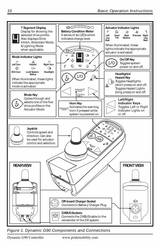
Dynamic G90 Controller FeaturesFigure 1 provides information on the Dynamic G90 components andconnections. Use this diagram to familiarize yourself with the function andlocation of each component before using the Dynamic G90 controller.
The following functions are available with the Dynamic G90 controller:Joystick ControlThe joystick is used to control the direction and speed of the powerchair.
Actuator AdjustmentThe user can control positioning of the power actuators with theDynamic G90 controller.
Drive Profile SelectionThe user can select one of five available drive profiles.
Sleep ModeThis feature is designed to preserve battery charge and can be disabledthrough programming.
Out of Neutral at Power Up (OONAPU)A safety feature designed to prevent the power chair from overheatingand causing damage to the motors or controller.
10 Basic Operation Instructions
Dynamic G90 Controller www.pridemobility.com
REARVIEW FRONTVIEW
Battery Condition MeterA series of six LEDs whichindicates charge level.
7 Segment DisplayDisplay for showing theselected drive profile.Also displays DriveInhibit, Attendant Mode,& Lighting Modewhen applicable.
Mode KeyCycles through andselects one of the fivedrive profiles or theActuator Mode.
JoystickControls speed anddirection. Can also be used for actuatorcontrol and selection.
On/Off KeyToggles systempower on and off.
Headlights/Hazard KeyToggles Headlights(short press) on and off.Toggles Hazard Lights(long press) on and off.
Horn KeyActivates the warninghorn if pressed whilesystem is powered on.
Left/RightIndicator KeysToggles Left or RightIndicator Lights onor off.
Mode Indicator Lights
When illuminated, these lightsindicate the appropriatemode is activated.
Actuator Indicator Lights
When illuminated, theselights indicate the appropriateactuator is activated.
LeftLegRest
Elevate RightLegRest
SeatTilt
BackRecline
LeftTurn Hazard
ECU Icon Headlight
RightTurn
Lock/SystemStatus
Off-board Charger SocketConnects to Battery Charger Plug.
DXBUS SocketsConnects the DXBUS cable to theremainder of the DX system.
Figure 1. Dynamic G90 Components and Connections

Basic Operation Instructions 11
www.pridemobility.com Dynamic G90 Controller
OPERATING THE DYNAMIC G90 CONTROLLERThe Dynamic G90 controller is used to operate your power chair and all ofits components.
The Dynamic G90 controller consists of (See figure 2):1. Joystick2. Keypad & display3. Controller communications connector4. 3-pin off-board charger socket
NOTE: This section describes standard Dynamic G90 control functions.If your controller is programmed with optional settings, consult yourauthorized Pride Provider for specific operational information.
Joystick ControlThe joystick controls the direction and speed of your power chair. When youmove the joystick from the neutral (center) position, the electromagneticbrakes release and allow your power chair to move. The farther you push thejoystick from its neutral position, the faster your power chair moves. Whenyou release the joystick and allow it to return to the neutral position, youengage the electromagnetic brakes. This causes your power chair to decel-erate and come to a complete stop.
Keypad and DisplayThe keypad and display is located directly in front of the joystick. It containskeys and icons that you will use to control your power chair. See figure 3.
On/Off KeyThe on/off key turns the system on and off.
WARNING! Unless faced with an emergency situation, donot use the on/off key to stop the chair. This will cause thepower chair to stop abruptly.
WARNING! Always turn the power off when you arestationary to prevent unexpected movement.
NOTE: If the joystick is not in the neutral (center) position when you turnon the power, you may cause a fault in the system. See “Out Of Neutral AtPower Up.”
12 Basic Operation Instructions
Dynamic G90 Controller www.pridemobility.com
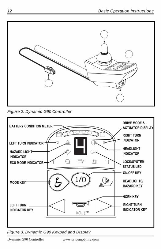
Figure 2. Dynamic G90 Controller
�
�
�
�
Figure 3. Dynamic G90 Keypad and Display
BATTERY CONDITION METER
LEFT TURN INDICATOR
ECU MODE INDICATOR
MODE KEY
LEFT TURN INDICATOR KEY
RIGHT TURN INDICATOR KEY
HORN KEY
HEADLIGHTS/HAZARD KEY
RIGHT TURN INDICATOR
HEADLIGHTINDICATOR
LOCK/SYSTEM STATUS LEDON/OFF KEY
DRIVE MODE & ACTUATOR DISPLAY
HAZARD LIGHTINDICATOR

Basic Operation Instructions 13
www.pridemobility.com Dynamic G90 Controller
Lock/System Status LEDThe lock/system status LED is normally on when the system is powered up,and off when the system is powered down. See figure 3. This light will flashgreen if there is an internal fault, or if an OONAPU fault has occurred. See“Out Of Neutral At Power Up.”
The lock/system status LED also serves as the magnetic locking area, a fea-ture that enables you to “lockout” unauthorized users. For this function, youwill need the magnetic key supplied with your power chair. If you lose thiskey, contact your authorized Pride Provider.
To enable the lockout system:1. Swipe the magnetic key across the lock/system status LED. See figure 3.
The system will beep and automatically turn off.
NOTE: None of the remote lights should be lit.
2. Press the on/off key to turn on the power chair. The lock/system statusLED will flash red, indicating that the system is locked. You will not beable to drive your power chair.
3. Swipe the magnetic key across the lock/system status LED again. Whenthe light stops flashing, the system is unlocked and the power chair willreturn to normal operation.
NOTE: If you turn on the power chair while it is locked and do not unlockit after one minute, the power chair will automatically turn itself off.
Battery Condition MeterThe battery condition meter consists of six lights arranged in an arc over the7 segment display. From left to right, the first two are red, the second twoare orange, and the last two are green. These lights give you an accurateindication of your usable battery capacity. If the battery has at least 85% ofits rated capacity, all of the lights will be on. As the battery voltage drops,the number of lights reduces from right to left. When the battery gauge dropsto the two red LEDs on the left, these LEDs will flash. When the batterycapacity drops to 10% or below, the left most red LED will flash.
NOTE: When the battery capacity drops to below 21V (typically twolights), the controller will reduce power chair performance to conservebattery power.
14 Basic Operation Instructions
Dynamic G90 Controller www.pridemobility.com
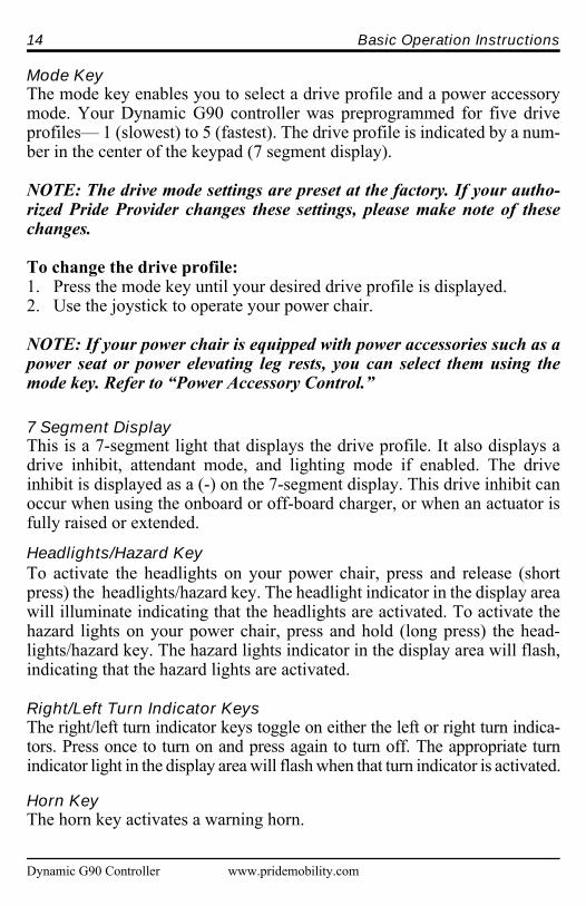
Mode KeyThe mode key enables you to select a drive profile and a power accessorymode. Your Dynamic G90 controller was preprogrammed for five driveprofiles— 1 (slowest) to 5 (fastest). The drive profile is indicated by a num-ber in the center of the keypad (7 segment display).
NOTE: The drive mode settings are preset at the factory. If your autho-rized Pride Provider changes these settings, please make note of thesechanges.
To change the drive profile:1. Press the mode key until your desired drive profile is displayed.2. Use the joystick to operate your power chair.
NOTE: If your power chair is equipped with power accessories such as apower seat or power elevating leg rests, you can select them using themode key. Refer to “Power Accessory Control.”
7 Segment DisplayThis is a 7-segment light that displays the drive profile. It also displays adrive inhibit, attendant mode, and lighting mode if enabled. The driveinhibit is displayed as a (-) on the 7-segment display. This drive inhibit canoccur when using the onboard or off-board charger, or when an actuator isfully raised or extended.
Headlights/Hazard KeyTo activate the headlights on your power chair, press and release (shortpress) the headlights/hazard key. The headlight indicator in the display areawill illuminate indicating that the headlights are activated. To activate thehazard lights on your power chair, press and hold (long press) the head-lights/hazard key. The hazard lights indicator in the display area will flash,indicating that the hazard lights are activated.
Right/Left Turn Indicator Keys The right/left turn indicator keys toggle on either the left or right turn indica-tors. Press once to turn on and press again to turn off. The appropriate turnindicator light in the display area will flash when that turn indicator is activated.
Horn KeyThe horn key activates a warning horn.

Basic Operation Instructions 15
CONTROLLER COMMUNICATIONS CONNECTORThis connects the Dynamic G90 to the power chair’s batteries, motors, andmotor brakes.
OFF-BOARD CHARGER SOCKETYou may use an off-board charger to charge the power chair batteries throughthe 3-pin socket located on the front of the Dynamic G90 (see figure 1). If youuse an off-board charger, the charger current should not exceed 8 amps. Con-tact your authorized Pride Provider for more information.
POWER ACCESSORY CONTROLThe Dynamic G90 controller can support the control of up to five poweraccessory actuators once the actuator control module is correctly config-ured. Power accessory actuators are selected using the mode key and con-trolled using the joystick.
To select a power accessory actuator:1. Press the mode key until the desired actuator is indicated by the
indicator lights located below the display. See figure 1.
NOTE: The power chair will not drive in this mode.
2. Push the joystick full forward or full reverse to control the actuatoradjustment.
NOTE: When using the Dynamic G90 in conjunction with a TRx SeatingSystem, give a reverse command to extend the actuator, release the joy-stick, then give another reverse command to retract the actuator. Thereverse command toggles between extend and retract only for TRx units.If you experience any problems with the operation of your TRx SeatingSystem or your power chair, contact your authorized Pride Provider.
3. Resume driving by moving the joystick back to neutral and selecting adrive program using the mode key.
BATTERY SAVER FEATUREWhen the battery capacity drops to below 21V (typically two lights), thecontroller will reduce power chair performance to conserve battery power.
www.pridemobility.com Dynamic G90 Controller
16 Basic Operation Instructions
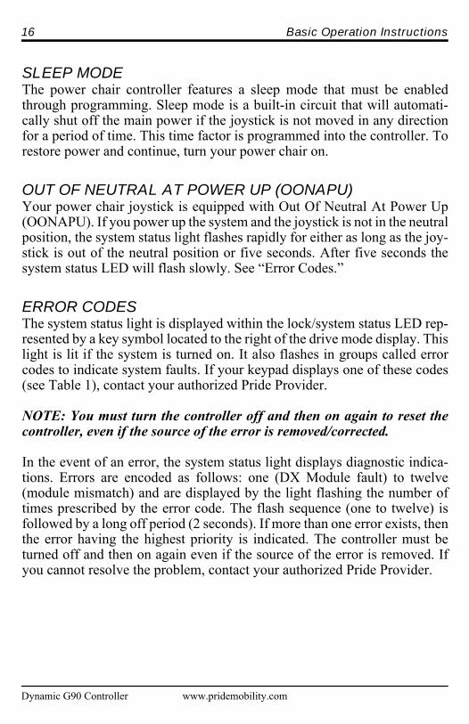
SLEEP MODE The power chair controller features a sleep mode that must be enabledthrough programming. Sleep mode is a built-in circuit that will automati-cally shut off the main power if the joystick is not moved in any directionfor a period of time. This time factor is programmed into the controller. Torestore power and continue, turn your power chair on.
OUT OF NEUTRAL AT POWER UP (OONAPU)Your power chair joystick is equipped with Out Of Neutral At Power Up(OONAPU). If you power up the system and the joystick is not in the neutralposition, the system status light flashes rapidly for either as long as the joy-stick is out of the neutral position or five seconds. After five seconds thesystem status LED will flash slowly. See “Error Codes.”
ERROR CODESThe system status light is displayed within the lock/system status LED rep-resented by a key symbol located to the right of the drive mode display. Thislight is lit if the system is turned on. It also flashes in groups called errorcodes to indicate system faults. If your keypad displays one of these codes(see Table 1), contact your authorized Pride Provider.
NOTE: You must turn the controller off and then on again to reset thecontroller, even if the source of the error is removed/corrected.
In the event of an error, the system status light displays diagnostic indica-tions. Errors are encoded as follows: one (DX Module fault) to twelve(module mismatch) and are displayed by the light flashing the number oftimes prescribed by the error code. The flash sequence (one to twelve) isfollowed by a long off period (2 seconds). If more than one error exists, thenthe error having the highest priority is indicated. The controller must beturned off and then on again even if the source of the error is removed. Ifyou cannot resolve the problem, contact your authorized Pride Provider.
Dynamic G90 Controller www.pridemobility.com

Basic Operation Instructions 17
www.pridemobility.com Dynamic G90 Controller
Table 1. Error Codes
Error Fault Diagnosis Solution Code
1 DX Module Fault An auto download has occurred. See your authorized PrideThe controller is not correctly Provider.programmed.The connection between the powermodule and the joystick module maybe faulty.
2 DX Accessory The accessory module (CLAM) has See your authorized PrideFault a fault. Provider.
3 Left Motor The connection between the power Check left motor writing.(or connection) module and the left motor is eitherFault open or is shorted or the motor
itself is shorted.4 Right Motor The connection between the power Check right motor writing.
(or connection) module and the right motor is eitherFault open or is shorted or the motor itself
is shorted.5 Left Park Brake The connection between the power Check motor/brake wiring.
(or connection) module and the left park brake isFault either open or shorted or the motor
brake itself is shorted.6 Right Park Brake The connection between the power Check motor/brake wiring.
(or connection) module and the right motor brake isFault either open or shorted or the motor
brake itself is shorted.7 Low Battery Fault Battery voltage has fallen below Check that the battery wiring
17 VDC. is secure.8 Over-voltage Fault The battery voltage has exceeded Check that the battery wiring
32VDC. is secure.9 CANL Fault The DX Bus cable has a short or See your authorized Pride
an open. Provider. 10 CANH Fault The DX Bus cable has a short or See your authorized Pride
an open. Provider. 11 Stall Timeout The motor has been close to or at Turn unit off, then on.
the programmed current limit. 12 Module Mismatch There is an incompatibility between See your authorized Pride
the DX modules in the system. Provider.

18 Basic Operation Instructions
Dynamic G90 Controller www.pridemobility.com
CARE AND MAINTENANCERefer to your power chair owner’s manual for proper cleaning and disposalinstructions.
WARRANTYFor two (2) years from the date of purchase, Pride will repair or replace atour option to the original purchaser, free of charge, the controller or any ofits components found upon examination by an authorized representative ofPride to be defective in material and/or workmanship.

www.pridemobility.com Dynamic G90 Controller
NOTES

*INFMANU3721*
Pride Mobility Products Corporation182 Susquehanna AvenueExeter, PA 18643-2694USA
Pride Mobility Products Company380 Vansickle Road Unit 350St. Catharines, Ontario L2R 6P7Canada
Pride Mobility Products Ltd.32 Wedgwood RoadBicester, Oxon OX26 4ULUK
Pride Mobility Products Australia Pty. Ltd.21 Healey RoadDandenong, 3175Victoria, Australia
Pride Mobility Products Italia S.r.l.Via del Progresso - ang. Via del LavoroLoc. Prato della Corte00065-Fiano Romano (RM)
Pride Mobility Products Europe B.V.Castricummer Werf 261901 RW CastricumThe Netherlands