troubleshooting the cisco pgw 2200 softswitch platform an element of the ethernet connection (such...
TRANSCRIPT

Cisco PGW 2200 Softswitch Release 9.8 OpOL-0800-14
C H A P T E R 6
Troubleshooting the Cisco PGW 2200 Softswitch PlatformRevised: March 7, 2011, OL-0800-14
This chapter describes troubleshooting methods for the Cisco PGW 2200 Softswitch platform. The following sections include instructions to help you isolate system problems:
• Troubleshooting Overview, page 6-1
• Troubleshooting Using Cisco PGW 2200 Softswitch Alarms, page 6-3
• Troubleshooting with System Logs, page 6-89
• Resolving SS7 Network Related Problems, page 6-94
• Resolving Bearer Channel Connection Problems, page 6-123
• Resolving SIP Communication Problems, page 6-155
• Tracing, page 6-155
• Platform Troubleshooting, page 6-169
Troubleshooting OverviewThis chapter presents the alarms and logs that the Cisco PGW 2200 Softswitch generates. Information provided by the alarms and log files help to isolate problems with the system. For complete lists of alarms and logs, see Cisco PGW 2200 Softswitch Release 9 Messages Reference.
Several of the corrective actions in this chapter point to other chapters in this manual. This chapter also refers to troubleshooting tools including the Cisco PGW 2200 Softswitch software, the Cisco WAN Manager, the Cisco Media Gateway Controller Node Manager (CMNM), and CiscoWorks.
The chapter describes ways to troubleshoot typical problems. The examples provide a logical sequence for troubleshooting that you can use as a model.
Note To troubleshoot problems with the Cisco PGW 2200 Softswitch platform, users must have some experience administering the system, and must understand UNIX at the system administrator level.
6-1erations, Maintenance, and Troubleshooting Guide

Chapter 6 Troubleshooting the Cisco PGW 2200 Softswitch PlatformTroubleshooting Overview
The following sections present solutions to various equipment failure scenarios:
• Cisco ITP-L Failure
• Cisco PGW 2200 Softswitch Failure
• Operating System Failure
Cisco ITP-L FailureEach Cisco IP Transfer Point LinkExtender (ITP-L) has a Reliable User Datagram Protocol (RUDP)/User Datagram Protocol (UDP)/IP connection to each Cisco PGW 2200 Softswitch for the transfer of Message Transfer Part (MTP) Level 3 (MTP3), ISDN User Part (ISUP), and Transaction Capabilities Application Part (TCAP) information. A Cisco ITP-L platform failure causes the surviving Cisco ITP-L platforms to take over the distribution of messages to the active Cisco PGW 2200 Softswitch. You should provision Cisco ITP-L platforms so that half of the platforms can support the entire signaling load. A single Cisco ITP-L platform failure should not have a significant effect on call processing.
There are several Cisco ITP-L failure scenarios to consider:
• IP link failure between the Cisco ITP-L and the Cisco PGW 2200 Softswitch, which indicates that it is impossible to transfer MTP3 messages. In this case, MTP Level 2 (MTP2) transmits Status Indication Processor Outage (SIPO) messages to the signaling transfer point (STP) to begin switchover to another Cisco ITP-L.
• If MTP2 failed (equivalent to a Cisco ITP-L failure), no SIPO messages are sent because MTP2 is inoperable. Instead, the mated STP pair detects the failure because of timer expiration or link unavailability and starts the switchover to another SS7 link.
• If a Cisco ITP-L timer detects a Cisco PGW 2200 Softswitch fault, a coordination mechanism causes SS7 messaging to flow to the newly active (formerly standby) Cisco PGW 2200 Softswitch. The standby Cisco PGW 2200 Softswitch assumes control for all calls in progress and all new calls.
Cisco PGW 2200 Softswitch FailureCisco PGW 2200 Softswitches run in active-standby mode. The call-processing application is active on only one Cisco PGW 2200 Softswitch at a time, and the application switches to the standby platform when a critical alarm occurs. Consequently, a Cisco PGW 2200 Softswitch failure and switchover events are invisible to the SS7 signaling network.
Cisco PGW 2200 Softswitch alarms can be minor, major, or critical. Critical alarms are generated whenever any significant failure occurs. Any critical alarm causes a switchover to occur. For example, if the call engine or I/O channel controller (IOCC)-MTP in the active Cisco PGW 2200 Softswitch fails, there is a disconnection from the process manager and a switchover to the standby Cisco PGW 2200 Softswitch.
Operating System FailureAn operating system or hardware failure in the active Cisco PGW 2200 Softswitch can also cause a switchover to the standby Cisco PGW 2200 Softswitch. The failover daemon in the standby Cisco PGW 2200 Softswitch detects the failure of the active Cisco PGW 2200 Softswitch and instructs the process manager to start a switchover. The standby Cisco PGW 2200 Softswitch then takes over all call-processing functions. The switchover is transparent to all Cisco ITP-Ls.
6-2Cisco PGW 2200 Softswitch Release 9.8 Operations, Maintenance, and Troubleshooting Guide
OL-0800-14
Chapter 6 Troubleshooting the Cisco PGW 2200 Softswitch PlatformTroubleshooting Using Cisco PGW 2200 Softswitch Alarms
Troubleshooting Using Cisco PGW 2200 Softswitch AlarmsThe Cisco PGW 2200 Softswitch generates alarms to indicate problems with processes, routes, linksets, signaling links, and bearer channels. The Cisco PGW 2200 Softswitch Release 9 Messages Reference lists all of the Cisco PGW 2200 Softswitch alarms and logs, and provides descriptions, possible causes, and suggested actions. You can find procedures for alarms that require you to take corrective action in the “Alarm Troubleshooting Procedures” section on page 6-4.
The active alarm log files reside in the /opt/CiscoMGC/var/log directory. These alarm log files are archived based on the criteria that are set in the dmprSink.dat file. For more information on the dmprSink.dat file, see the “Configuring the Data Dumper” section on page A-2.
The following sections describe troubleshooting using the Cisco PGW 2200 Softswitch alarms:
• Retrieving All Active Alarms, page 6-3
• Acknowledging Alarms, page 6-3
• Alarm Troubleshooting Procedures, page 6-4
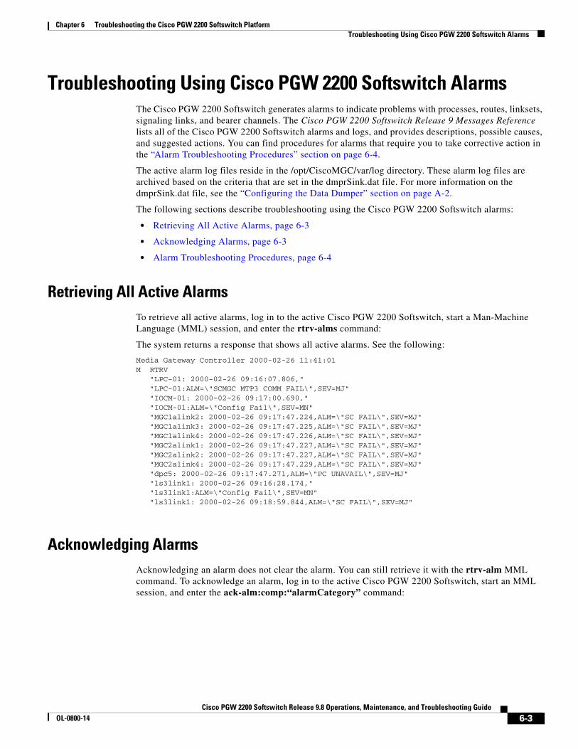
Retrieving All Active AlarmsTo retrieve all active alarms, log in to the active Cisco PGW 2200 Softswitch, start a Man-Machine Language (MML) session, and enter the rtrv-alms command:
The system returns a response that shows all active alarms. See the following:
Media Gateway Controller 2000-02-26 11:41:01M RTRV "LPC-01: 2000-02-26 09:16:07.806," "LPC-01:ALM=\"SCMGC MTP3 COMM FAIL\",SEV=MJ" "IOCM-01: 2000-02-26 09:17:00.690," "IOCM-01:ALM=\"Config Fail\",SEV=MN" "MGC1alink2: 2000-02-26 09:17:47.224,ALM=\"SC FAIL\",SEV=MJ" "MGC1alink3: 2000-02-26 09:17:47.225,ALM=\"SC FAIL\",SEV=MJ" "MGC1alink4: 2000-02-26 09:17:47.226,ALM=\"SC FAIL\",SEV=MJ" "MGC2alink1: 2000-02-26 09:17:47.227,ALM=\"SC FAIL\",SEV=MJ" "MGC2alink2: 2000-02-26 09:17:47.227,ALM=\"SC FAIL\",SEV=MJ" "MGC2alink4: 2000-02-26 09:17:47.229,ALM=\"SC FAIL\",SEV=MJ" "dpc5: 2000-02-26 09:17:47.271,ALM=\"PC UNAVAIL\",SEV=MJ" "ls3link1: 2000-02-26 09:16:28.174," "ls3link1:ALM=\"Config Fail\",SEV=MN" "ls3link1: 2000-02-26 09:18:59.844,ALM=\"SC FAIL\",SEV=MJ"
Acknowledging AlarmsAcknowledging an alarm does not clear the alarm. You can still retrieve it with the rtrv-alm MML command. To acknowledge an alarm, log in to the active Cisco PGW 2200 Softswitch, start an MML session, and enter the ack-alm:comp:“alarmCategory” command:
6-3Cisco PGW 2200 Softswitch Release 9.8 Operations, Maintenance, and Troubleshooting Guide
OL-0800-14

Chapter 6 Troubleshooting the Cisco PGW 2200 Softswitch PlatformTroubleshooting Using Cisco PGW 2200 Softswitch Alarms
Where:
• comp—MML name of the component. For a complete list of components, see the Cisco PGW 2200 Softswitch Release 9.8 Provisioning Guide. You can retrieve a list of provisioned components by entering the prov-rtrv:all MML command.
• alarmCategory—MML name of the associated alarm category. The name you enter must match exactly the name of the alarm as it is displayed.
For example, to acknowledge a signaling channel fail alarm (SC FAIL) that occurred on the link MGC2alink1, enter the ack-alm:MGC2alink1:“SC Fail” command:
Alarm Troubleshooting ProceduresThis section contains alarms that require you to take corrective action. For a complete list of alarms, including alarms that do not require you to take corrective action, see Cisco PGW 2200 Softswitch Release 9 Messages Reference.
All Conn Cntl Links Fail
This alarm occurs when the MGCP session loses a heartbeat, which indicates that the session is down.
Corrective Action
To correct the problem that this alarm identifies, perform the following steps:
Step 1 Follow the procedure to collect system data, which is detailed in the “Collecting System Data for Cisco TAC” section on page 6-93.
Step 2 Verify that the Ethernet interfaces between the Cisco PGW 2200 Softswitch and the associated media gateway are working properly.
Note To find information on verifying the proper operation of an Ethernet interface on the Cisco PGW 2200 Softswitch, see the Sun Microsystems documentation that came with your system. For information on verifying the proper functioning of an Ethernet interface on the media gateway, see the documentation for the specific media gateway.
If an element of the Ethernet connection (such as a cable or an Ethernet interface card) is not working properly, replace it. Otherwise, proceed to Step 3.
Note To find information on removing and replacing an Ethernet interface card on the Cisco PGW 2200 Softswitch, see the Sun Microsystems documentation that came with your system. For information on removing and replacing an Ethernet interface card on the media gateway, see the documentation for the specific media gateway.
Step 3 Verify that the near-end and far-end MGCP sessions are operating normally. See the documentation for the affected media gateway.
6-4Cisco PGW 2200 Softswitch Release 9.8 Operations, Maintenance, and Troubleshooting Guide
OL-0800-14
Chapter 6 Troubleshooting the Cisco PGW 2200 Softswitch PlatformTroubleshooting Using Cisco PGW 2200 Softswitch Alarms
Step 4 Contact the Cisco TAC to analyze the problem further and to determine a solution. For more information about contacting the Cisco TAC, see the “Obtaining Documentation and Submitting a Service Request” section on page xviii.
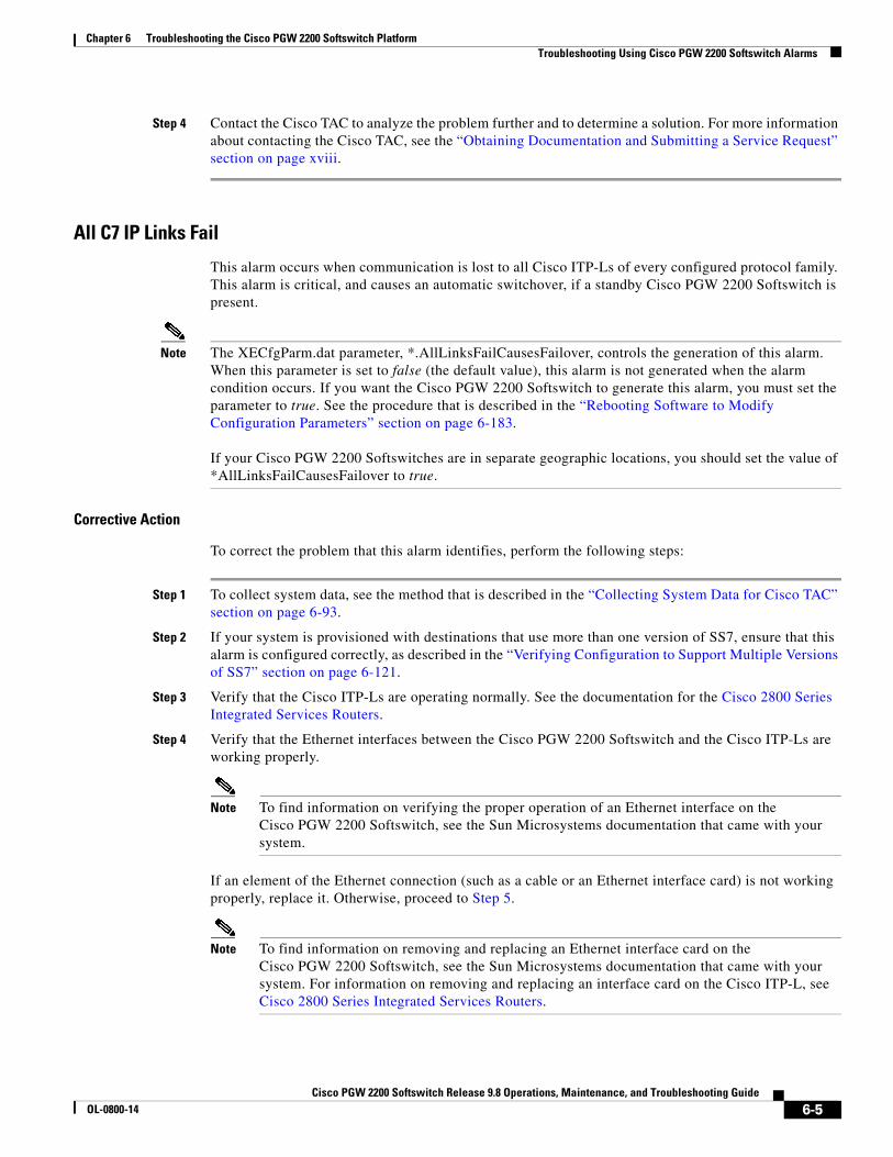
All C7 IP Links Fail
This alarm occurs when communication is lost to all Cisco ITP-Ls of every configured protocol family. This alarm is critical, and causes an automatic switchover, if a standby Cisco PGW 2200 Softswitch is present.
Note The XECfgParm.dat parameter, *.AllLinksFailCausesFailover, controls the generation of this alarm. When this parameter is set to false (the default value), this alarm is not generated when the alarm condition occurs. If you want the Cisco PGW 2200 Softswitch to generate this alarm, you must set the parameter to true. See the procedure that is described in the “Rebooting Software to Modify Configuration Parameters” section on page 6-183.
If your Cisco PGW 2200 Softswitches are in separate geographic locations, you should set the value of *AllLinksFailCausesFailover to true.
Corrective Action
To correct the problem that this alarm identifies, perform the following steps:
Step 1 To collect system data, see the method that is described in the “Collecting System Data for Cisco TAC” section on page 6-93.
Step 2 If your system is provisioned with destinations that use more than one version of SS7, ensure that this alarm is configured correctly, as described in the “Verifying Configuration to Support Multiple Versions of SS7” section on page 6-121.
Step 3 Verify that the Cisco ITP-Ls are operating normally. See the documentation for the Cisco 2800 Series Integrated Services Routers.
Step 4 Verify that the Ethernet interfaces between the Cisco PGW 2200 Softswitch and the Cisco ITP-Ls are working properly.
Note To find information on verifying the proper operation of an Ethernet interface on the Cisco PGW 2200 Softswitch, see the Sun Microsystems documentation that came with your system.
If an element of the Ethernet connection (such as a cable or an Ethernet interface card) is not working properly, replace it. Otherwise, proceed to Step 5.
Note To find information on removing and replacing an Ethernet interface card on the Cisco PGW 2200 Softswitch, see the Sun Microsystems documentation that came with your system. For information on removing and replacing an interface card on the Cisco ITP-L, see Cisco 2800 Series Integrated Services Routers.
6-5Cisco PGW 2200 Softswitch Release 9.8 Operations, Maintenance, and Troubleshooting Guide
OL-0800-14

Chapter 6 Troubleshooting the Cisco PGW 2200 Softswitch PlatformTroubleshooting Using Cisco PGW 2200 Softswitch Alarms
Step 5 Verify that the configuration for your system is correct. To verify the provisioning data for your Cisco PGW 2200 Softswitch, use the prov-rtrv MML command, as described in the “Retrieving Provisioning Data” section on page 3-69. To verify the provisioning data for the Cisco ITP-Ls, use the show commands.
If the configuration of the Cisco PGW 2200 Softswitch is incorrect, begin a dynamic reconfiguration session, as described in the “Invoking Dynamic Reconfiguration” section on page 3-66.
If the configuration of the Cisco ITP-Ls is incorrect, modify the provisioning data for your system. See Cisco Signaling Link Terminal document for more information.
If the configuration of both the Cisco PGW 2200 Softswitch and the Cisco ITP-Ls are correct, proceed to Step 6.
Step 6 Contact the Cisco TAC to analyze the problem further and to determine a solution. For more information about contacting the Cisco TAC, see the “Obtaining Documentation and Submitting a Service Request” section on page xviii.
All ISDN BRI IP Conn Fail
This alarm occurs when all IP connections that support an ISDN BRI data pathway have failed.
Corrective Action
To correct the problem that this alarm identifies, perform the following steps:
Step 1 To collect system data, see the method that is described in the “Collecting System Data for Cisco TAC” section on page 6-93.
Step 2 Determine the health of the associated media gateway by using the procedures in the user documentation for the media gateway.
If the media gateway is working correctly, proceed to Step 3.
If the media gateway is not working correctly, restore it using the procedures in the user documentation for the media gateway. If those procedures restore the media gateway and this alarm clears, the procedure is complete. Otherwise, proceed to Step 3.
Step 3 Verify the cabling between the Cisco PGW 2200 Softswitch and the switch is functioning.
If the cables are functioning properly, proceed to Step 4.
If you find a bad cable, replace it. If replacing a cable resolves the problem, the procedure is complete. Otherwise, proceed to Step 4.
Step 4 Verify the functioning of the associated switch. See the documentation for the switch for the necessary steps.
If the switch is functioning properly, proceed to Step 5.
If the switch is not functioning properly, see the appropriate troubleshooting procedures in the documentation for the switch. If those methods correct the problem, the procedure is complete. Otherwise, proceed to Step 7.
6-6Cisco PGW 2200 Softswitch Release 9.8 Operations, Maintenance, and Troubleshooting Guide
OL-0800-14

Chapter 6 Troubleshooting the Cisco PGW 2200 Softswitch PlatformTroubleshooting Using Cisco PGW 2200 Softswitch Alarms
Step 5 Check the IP connectivity between the Cisco PGW 2200 Softswitch and the associated Cisco BRI voice gateway.
If the IP connectivity is good, proceed to Step 6.
If the IP connectivity is bad, restore the IP connectivity. If the alarm clears after the IP connectivity is restored, the procedure is complete. Otherwise, proceed to Step 6.
Step 6 Verify that the provisioning data for your ISDN BRI backhaul connect is correct. To verify the provisioning data, use the prov-rtrv MML command, as described in the “Retrieving Provisioning Data” section on page 3-69.
If the provisioning data is correct, proceed to Step 7.
If the provisioning data is not correct, begin a dynamic reconfiguration session, as described in the “Invoking Dynamic Reconfiguration” section on page 3-66.
Step 7 Contact the Cisco TAC to analyze the problem further and to determine a solution. For more information about contacting the Cisco TAC, see the “Obtaining Documentation and Submitting a Service Request” section on page xviii.
All ISDN IP Conn Fail
This alarm occurs when communication is lost to all ISDN IP connections. The severity of this alarm is Critical, which causes an automatic switchover if a standby Cisco PGW 2200 Softswitch is present.
Note The ability to change the severity level of this alarm is implemented in the patch (CSCOgs059) for Release 9.5(2). The XECfgParm.dat parameter, *.AllISDNLinksFailCausesFailover, now controls the severity level of this alarm. When this parameter is set to false (the default value), this alarm has a severity level of Major. If you set this parameter to true, this alarm has a severity level of Critical.
This parameter should be set to true if the Cisco PGW 2200 Softswitches are in separate geographic locations. You can also set this parameter to true if the system is not processing SS7 calls and you want your system to perform an automatic switchover if all the ISDN IP connections fail. To change the value of this parameter, use the procedure that is defined in the “Rebooting Software to Modify Configuration Parameters” section on page 6-183.
Corrective Action
To correct the problem that this alarm identifies, perform the following steps:
Step 1 To collect system data, see the method that is described in the “Collecting System Data for Cisco TAC” section on page 6-93.
Step 2 Verify that the affected media gateways are operating normally, as described in the associated documentation.
Step 3 Verify that the Ethernet interfaces between the Cisco PGW 2200 Softswitch and the media gateways are working properly.
6-7Cisco PGW 2200 Softswitch Release 9.8 Operations, Maintenance, and Troubleshooting Guide
OL-0800-14

Chapter 6 Troubleshooting the Cisco PGW 2200 Softswitch PlatformTroubleshooting Using Cisco PGW 2200 Softswitch Alarms
Note To find information on verifying the proper operation of an Ethernet interface on the Cisco PGW 2200 Softswitch, see the Sun Microsystems documentation that came with your system. For information on verifying the proper functioning of an Ethernet interface on a media gateway, see the documentation for the specific media gateway.
If an element of the Ethernet connection (such as a cable or an Ethernet interface card) is not working properly, replace it. Otherwise, proceed to Step 4.
Note You can find information on removing and replacing an Ethernet interface card on the Cisco PGW 2200 Softswitch in the Sun Microsystems documentation that came with your system. For information on verifying the proper functioning of an Ethernet interface on a media gateway, see the documentation for the specific media gateway.
Step 4 Verify that the configuration for your system is correct. To verify the provisioning data for the Cisco PGW 2200 Softswitch, use the prov-rtrv MML command, as described in the “Retrieving Provisioning Data” section on page 3-69. To verify the provisioning data for the media gateways, use show commands, as described in the associated documentation.
If the configuration of the Cisco PGW 2200 Softswitch is incorrect, begin a dynamic reconfiguration session, as described in the “Invoking Dynamic Reconfiguration” section on page 3-66.
If the configuration of the media gateways is incorrect, modify the provisioning data for the media gateways. See the documentation that is associated with the media gateway for more information.
If the configuration of the Cisco PGW 2200 Softswitch and the media gateways are correct, then proceed to Step 5.
Step 5 Contact the Cisco TAC to analyze the problem further and to determine a solution. For more information about contacting the Cisco TAC, see the “Obtaining Documentation and Submitting a Service Request” section on page xviii.
All M3UAKEY Ack Pending
This alarm occurs when the Cisco PGW 2200 Softswitch cannot send or receive traffic for the identified SS7 signaling service that is associated with a Cisco ITP.
Corrective Action
To correct the problem that this alarm identifies, perform the following steps:
Step 1 To collect system data, see the method that is described in the “Collecting System Data for Cisco TAC” section on page 6-93.
Step 2 Determine the AS definitions on the associated Cisco ITP. See the documentation for your Cisco ITP for more information.
Step 3 Retrieve the settings for the affected M3UA routing keys using the prov-rtrv MML command, as described in the “Retrieving Provisioning Data” section on page 3-69.
Step 4 The AS definitions should match the routing contexts of the M3UA routing keys. If they match, proceed to Step 6. Otherwise, proceed to Step 5.
6-8Cisco PGW 2200 Softswitch Release 9.8 Operations, Maintenance, and Troubleshooting Guide
OL-0800-14

Chapter 6 Troubleshooting the Cisco PGW 2200 Softswitch PlatformTroubleshooting Using Cisco PGW 2200 Softswitch Alarms
Step 5 Open a dynamic reconfiguration session to modify the routing contexts of the M3UA routing keys, as described in the “Invoking Dynamic Reconfiguration” section on page 3-66.
If modifying the routing contexts corrects the problem, the procedure is complete. Otherwise, proceed to Step 6.
Step 6 Verify that the AS is not shutdown on the Cisco ITP. See the documentation for your Cisco ITP for more information. If the AS is shut down, restart it. Otherwise, proceed to Step 7.
If tending to the AS corrects the problem, the procedure is complete. Otherwise, proceed to Step 7.
Step 7 Contact the Cisco TAC to analyze the problem further and to determine a solution. For more information about contacting the Cisco TAC, see the “Obtaining Documentation and Submitting a Service Request” section on page xviii.
Note If you modify an ss7path that is configured for M3UAKEY, the system generates the “All M3UAKEY Ack Pending“ alarm for all the other ss7paths that are configured with the same M3UAKEY, although they are not being modified.
Coincidentally, when you modify an ss7path, the system generates the M3UAKEY Ack Pending alarms when the prov-cpy and prov-dply commands are being processed. However, these alarms are cleared after the commands have been completed.
When the prov-cpy and prov-dply commands are being processed, no new calls can be placed on any of the ss7paths for which alarms were generated. However, the calls that already exist on the ss7paths are not affected.
All M3UA Assoc Fail
This alarm occurs when all M3UA associations transporting SS7 signaling have failed.
Note The XECfgParm.dat parameter, *.AllLinksFailCausesFailover, now controls the generation of this alarm. When this parameter is set to false (the default value), this alarm is not generated when the alarm condition occurs. For the Cisco PGW 2200 Softswitch to generate this alarm, set the parameter to true, by using the procedure that is defined in the “Rebooting Software to Modify Configuration Parameters” section on page 6-183.
If the Cisco PGW 2200 Softswitches are in separate geographic locations, set the value of *AllLinksFailCausesFailover to true.
Corrective Action
To correct the problem that this alarm identifies, perform the following steps:
Step 1 To collect system data, see the method that is described in the “Collecting System Data for Cisco TAC” section on page 6-93.
Step 2 Verify that the Cisco ITPs are operating normally. See the documentation for your Cisco ITP for more information.
6-9Cisco PGW 2200 Softswitch Release 9.8 Operations, Maintenance, and Troubleshooting Guide
OL-0800-14

Chapter 6 Troubleshooting the Cisco PGW 2200 Softswitch PlatformTroubleshooting Using Cisco PGW 2200 Softswitch Alarms
If ensuring that the Cisco ITPs operate normally corrects the problem, the procedure is complete. Otherwise, proceed to Step 3.
Step 3 Verify that the Ethernet interfaces between the Cisco PGW 2200 Softswitch and the Cisco ITPs are working properly.
Note For information on verifying the proper operation of an Ethernet interface on the Cisco PGW 2200 Softswitch, see the Sun Microsystems documentation that came with your system. For information on verifying the proper functioning of an Ethernet interface on a Cisco ITP, see the documentation for the Cisco ITP.
If an element of the Ethernet connection (such as a cable or an Ethernet interface card) is not working properly, replace it. Otherwise, proceed to Step 4.
Note For information on removing and replacing an Ethernet interface card on the Cisco PGW 2200 Softswitch, see the Sun Microsystems documentation that came with your system. For information on removing and replacing an Ethernet interface card on the Cisco ITP, see the documentation for the Cisco ITP.
Step 4 Verify that the M3UA provisioning data on the Cisco PGW 2200 Softswitch is correct.
If the provisioning data is correct, proceed to Step 6. Otherwise, proceed to Step 5.
Step 5 Open a dynamic reconfiguration session to modify the M3UA provisioning data, as described in the “Invoking Dynamic Reconfiguration” section on page 3-66.
If modifying the M3UA provisioning data corrects the problem, the procedure is complete. Otherwise, proceed to Step 6.
Step 6 Contact the Cisco TAC to analyze the problem further and to determine a solution. For more information about contacting the Cisco TAC, see the “Obtaining Documentation and Submitting a Service Request” section on page xviii.
All SUAKEY Ack Pending
This alarm occurs when the Cisco PGW 2200 Softswitch cannot send or receive traffic for the identified SS7 subsystem.
Corrective Action
To correct the problem that this alarm identifies, perform the following steps:
Step 1 To collect system data, see the method that is described in the “Collecting System Data for Cisco TAC” section on page 6-93.
Step 2 Determine the AS definitions on the associated Cisco ITP. See the documentation for your Cisco ITP for more information.
Step 3 Retrieve the settings for the affected SUA routing keys using the prov-rtrv MML command, as described in the “Retrieving Provisioning Data” section on page 3-69.
Step 4 The AS definitions should match the routing contexts of the SUA routing keys. If they match, proceed to Step 6. Otherwise, proceed to Step 5.
6-10Cisco PGW 2200 Softswitch Release 9.8 Operations, Maintenance, and Troubleshooting Guide
OL-0800-14

Chapter 6 Troubleshooting the Cisco PGW 2200 Softswitch PlatformTroubleshooting Using Cisco PGW 2200 Softswitch Alarms
Step 5 Open a dynamic reconfiguration session to modify the routing contexts of the M3UA routing keys, as described in the “Invoking Dynamic Reconfiguration” section on page 3-66.
If modifying the routing contexts of the M3UA routing keys corrects the problem, the procedure is complete. Otherwise, proceed to Step 6.
Step 6 Verify that the AS is not shut down on the Cisco ITP. See the documentation for your Cisco ITP for more information. If the AS is shut down, restart it. Otherwise, proceed to Step 7.
If tending to the AS corrects the problem, the procedure is complete. Otherwise, proceed to Step 7.
Step 7 Contact the Cisco TAC to analyze the problem further and to determine a solution. For more information about contacting the Cisco TAC, see the “Obtaining Documentation and Submitting a Service Request” section on page xviii.
All SUA Assoc Fail
This alarm occurs when all SUA associations transporting SS7 signaling have failed.
Note The XECfgParm.dat parameter, *.AllLinksFailCausesFailover, now controls the generation of this alarm. When this parameter is set to false (the default value), this alarm is not generated when the alarm condition occurs. For the Cisco PGW 2200 Softswitch to generate this alarm, set the parameter to true, by using the procedure that is defined in the “Rebooting Software to Modify Configuration Parameters” section on page 6-183.
If the Cisco PGW 2200 Softswitches are in separate geographic locations, set the value of *AllLinksFailCausesFailover to true.
Corrective Action
To correct the problem, perform the following steps:
Step 1 To collect system data, see the method that is described in the “Collecting System Data for Cisco TAC” section on page 6-93.
Step 2 Verify that the Cisco ITPs are operating normally. See the documentation for your Cisco ITP for more information.
If ensuring that the Cisco ITPs are operating normally corrects the problem, the procedure is complete. Otherwise, proceed to Step 3.
Step 3 Verify that the Ethernet interfaces between the Cisco PGW 2200 Softswitch and the Cisco ITPs are working properly.
Note For information on verifying the proper operation of an Ethernet interface on the Cisco PGW 2200 Softswitch, see the Sun Microsystems documentation that came with your system. For information on verifying the proper functioning of an Ethernet interface on a Cisco ITP, see the documentation for the Cisco ITP.
If an element of the Ethernet connection (such as a cable or an Ethernet interface card) is not working properly, replace it. Otherwise, proceed to Step 4.
6-11Cisco PGW 2200 Softswitch Release 9.8 Operations, Maintenance, and Troubleshooting Guide
OL-0800-14

Chapter 6 Troubleshooting the Cisco PGW 2200 Softswitch PlatformTroubleshooting Using Cisco PGW 2200 Softswitch Alarms
Note For information on removing and replacing an Ethernet interface card on the Cisco PGW 2200 Softswitch, see the Sun Microsystems documentation that came with your system. For information on removing and replacing an Ethernet interface card on the Cisco ITP, see the documentation for the Cisco ITP.
Step 4 Verify that the SUA provisioning data on the Cisco PGW 2200 Softswitch is correct.
If the provisioning data is correct, proceed to Step 6. Otherwise, proceed to Step 5.
Step 5 Open a dynamic reconfiguration session to modify the SUA provisioning data, as described in the “Invoking Dynamic Reconfiguration” section on page 3-66.
If modifying the SUA provisioning data corrects the problem, the procedure is complete. Otherwise, proceed to Step 6.
Step 6 Contact the Cisco TAC to analyze the problem further and to determine a solution. For more information about contacting the Cisco TAC, see the “Obtaining Documentation and Submitting a Service Request” section on page xviii.
ANAL: ALoopCtrExceeded
This alarm occurs when an A-number analysis operation has gone into an infinite loop. The purpose of the alarm is to limit the number of passes spent in the analysis tree to 30.
Corrective Action
To correct the problem, perform the following steps:
Step 1 To collect system data, see the method that is described in the “Collecting System Data for Cisco TAC” section on page 6-93.
Step 2 Validate that there are no infinite loops in the A-number dial plan, as described in the “Verifying a Dial Plan Translation” section on page 3-135.
If there are infinite loops in your A-number dial plan, modify the settings in your A-number dial plan to remove the infinite loops, using the numan-ed MML command. See Cisco PGW 2200 Softswitch Release 9.8 Dial Plan Guide for more information. Save and activate your dial plan changes as described in the “Saving and Activating your Provisioning Changes” section on page 3-65.
If there are no infinite loops in your A-number dial plan, proceed to Step 3.
Step 3 Contact the Cisco TAC to analyze the problem further and to determine a solution. For more information about contacting the Cisco TAC, see the “Obtaining Documentation and Submitting a Service Request” section on page xviii.
ANAL: ATableFail_GetDigMod
This alarm occurs when an attempt to retrieve a modification string fails during A-number analysis. The problem occurs when the modification table is not loaded or the system provides a pointer to a nonexistent location in the modification table.
6-12Cisco PGW 2200 Softswitch Release 9.8 Operations, Maintenance, and Troubleshooting Guide
OL-0800-14

Chapter 6 Troubleshooting the Cisco PGW 2200 Softswitch PlatformTroubleshooting Using Cisco PGW 2200 Softswitch Alarms
Corrective Action
To correct the problem that this alarm identifies, verify that the dial plan file was loaded correctly, by using the procedure that is described in “Verifying Proper Loading of a Dial Plan” section on page 6-121.
ANAL: ATableFail_GetResult
This alarm occurs when access to the result table failed during A-number analysis. The problem occurs if the result table is not loaded or the system provides a pointer to a nonexistent location in the result table.
Corrective Action
To correct the problem, verify that the dial plan file was loaded correctly, using the procedure that is described in “Verifying Proper Loading of a Dial Plan” section on page 6-121.
ANAL: ATableFlt_DgtRangeError
This alarm occurs when the A-number analysis digit tree has been accessed with a digit that is out of range for the digit tree table. This alarm could occur if the system was incorrectly configured to support a base 10 dial plan, and an overdecadic digit was received from the line and passed to analysis.
Corrective Action
To correct the problem, perform the following steps:
Step 1 To collect system data, see the method that is described in the “Collecting System Data for Cisco TAC” section on page 6-93.
Step 2 Verify that the parameter, *.OverdecadicDigitsEnabled, is set correctly in the XECfgParm.dat file on each host.
Note The setting of this parameter should reflect the dial plan restrictions for the protocol in use. If the configured protocol supports the use of overdecadic digits, you should set the parameter to true. If the configured protocol does not support the use of overdecadic digits, you should set the parameter to false.
If the setting for the parameter is correct, proceed to Step 3. Otherwise, reboot your software using the procedure that is described in the “Rebooting Software to Modify Configuration Parameters” section on page 6-183.
Step 3 If the setting for the parameter is false, check the received digit string for presence of an overdecadic digit. If the digit string does not have an overdecadic digit, proceed to Step 5. If the digit string does have an overdecadic digit, proceed to Step 4.
If the setting for the parameter is true, proceed to Step 5.
Step 4 Check the compliancy documentation for the configured protocol.
If the documentation indicates that overdecadic digits are supported, change the setting for the *.OverdecadicDigitsEnabled XECfgParm.dat parameter to true on both hosts, by using the procedure in the “Rebooting Software to Modify Configuration Parameters” section on page 6-183.
If the documentation indicates that overdecadic digits are not supported, proceed to Step 5.
6-13Cisco PGW 2200 Softswitch Release 9.8 Operations, Maintenance, and Troubleshooting Guide
OL-0800-14

Chapter 6 Troubleshooting the Cisco PGW 2200 Softswitch PlatformTroubleshooting Using Cisco PGW 2200 Softswitch Alarms
Step 5 Contact the Cisco TAC to analyze the problem further and to determine a solution. For more information about contacting the Cisco TAC, see the “Obtaining Documentation and Submitting a Service Request” section on page xviii.
ANAL: BLoopCtrExceeded
The alarm occurs when a B-number analysis operation has gone into an infinite loop. The purpose of the alarm is to limit the number of passes spent in the analysis tree to 30.
Corrective Action
To correct the problem, perform the following steps:
Step 1 To collect system data, see the method that is described in the “Collecting System Data for Cisco TAC” section on page 6-93.
Step 2 Validate that there are no infinite loops in the B-number dial plan, as described in the “Verifying a Dial Plan Translation” section on page 3-135.
If there are infinite loops in your B-number dial plan, modify the settings in your B-number dial plan to remove the infinite loops, by using the numan-ed MML command. See Cisco PGW 2200 Softswitch Release 9.8 Dial Plan Guide for more information. Save and activate your dial plan changes as described in the “Saving and Activating your Provisioning Changes” section on page 3-65.
If there are no infinite loops in your B-number dial plan, then proceed to Step 3.
Step 3 Contact the Cisco TAC to analyze the problem further and to determine a solution. For more information about contacting the Cisco TAC, see the “Obtaining Documentation and Submitting a Service Request” section on page xviii.
ANAL: BNum_GetFail_SrvcTbl
This alarm occurs during B-number analysis when a screening result is encountered and an attempt to read the service table to determine the name of the service performing the screening fails. This failure is because of corruption of either the result table or the service table.
Corrective Action
To correct the problem, verify that the dial plan file was loaded correctly, using the procedure that is described in “Verifying Proper Loading of a Dial Plan” section on page 6-121.
ANAL: BNum_MdfyBFail_ AnnounceID
This alarm occurs during B-number analysis when an announcement result is encountered and analysis is unable to replace the last four digits of the B-number with the announcement ID. An out-of-range announcement ID (it should be 0–9999) or a B-number less than four digits long commonly causes this replacement failure.
6-14Cisco PGW 2200 Softswitch Release 9.8 Operations, Maintenance, and Troubleshooting Guide
OL-0800-14

Chapter 6 Troubleshooting the Cisco PGW 2200 Softswitch PlatformTroubleshooting Using Cisco PGW 2200 Softswitch Alarms
Corrective Action
To correct the problem, perform the following steps:
Step 1 To collect system data, see the method that is described in the “Collecting System Data for Cisco TAC” section on page 6-93.
Step 2 Verify that all the configured announcement IDs are within the range 0 through 9999, by using the numan-rtrv MML command. See Cisco PGW 2200 Softswitch Release 9.8 Dial Plan Guide for more information.
If any of the announcement IDs are outside of the range, modify its value using the numan-ed MML command. See Cisco PGW 2200 Softswitch Release 9.8 Dial Plan Guide for more information. Save and activate your dial plan changes as described in the “Saving and Activating your Provisioning Changes” section on page 3-65. Otherwise, proceed to Step 3.
Step 3 Verify that the dial plan file was loaded correctly, using the procedure that is described in the “Verifying Proper Loading of a Dial Plan” section on page 6-121.
ANAL: BTableFail_GetDigTree
This alarm occurs if you specified an invalid path for B-number analysis or if the B-number analysis table is not loaded.
Corrective Action
To correct the problem that this alarm identifies, verify that the dial plan file was loaded correctly, by using the procedure that is described in the “Verifying Proper Loading of a Dial Plan” section on page 6-121.
ANAL: BTableFail_GetDigMod
This alarm occurs when an attempt to retrieve a modification string during B-number analysis fails. The problem occurs if the modification table is not loaded or the system provides a pointer to a nonexistent location in the modification table.
Corrective Action
To correct the problem, verify that the dial plan file was loaded correctly, by using the procedure that is described in the “Verifying Proper Loading of a Dial Plan” section on page 6-121.
ANAL: BTableFail_GetResult
This alarm occurs when access to the result table failed during B-number analysis. The problem occurs if the result table is not loaded or the system provides a pointer to a nonexistent location in the result table.
Corrective Action
To correct the problem, verify that the dial plan file was loaded correctly, by using the procedure that is described in the “Verifying Proper Loading of a Dial Plan” section on page 6-121.
6-15Cisco PGW 2200 Softswitch Release 9.8 Operations, Maintenance, and Troubleshooting Guide
OL-0800-14

Chapter 6 Troubleshooting the Cisco PGW 2200 Softswitch PlatformTroubleshooting Using Cisco PGW 2200 Softswitch Alarms
ANAL: BTableFlt_DgtRangeError
This alarm occurs when the B-number analysis digit tree has been accessed with a digit that is out of range for the digit tree table. This alarm could occur if the system was incorrectly configured to support a base 10 dial plan, and an overdecadic digit was received from the line and passed to analysis.
Corrective Action
To correct the problem, perform the following steps:
Step 1 To collect system data, see the method that is described in the “Collecting System Data for Cisco TAC” section on page 6-93.
Step 2 Verify that the parameter, *.OverdecadicDigitsEnabled, is set correctly in the XECfgParm.dat file on each host.
Note The setting of this parameter should reflect the dial plan restrictions for the protocol in use. If the configured protocol supports the use of overdecadic digits, set the parameter to true. If the configured protocol does not support the use of overdecadic digits, set the parameter to false.
If the setting for the parameter is correct, proceed to Step 3. Otherwise, update the parameter settings in the XECfgParm.dat files by using the procedure in the “Rebooting Software to Modify Configuration Parameters” section on page 6-183.
Step 3 If the setting for the parameter is false, check the received digit string for presence of an overdecadic digit. If the digit string does not have an overdecadic digit, proceed to Step 5. If the digit string does have an overdecadic digit, proceed to Step 4.
If the setting for the parameter is true, proceed to Step 5.
Step 4 Check the compliancy documentation for the configured protocol.
If the documentation indicates that overdecadic digits are supported, change the setting for the *.OverdecadicDigitsEnabled XECfgParm.dat parameter to true on each host using the procedure in the “Rebooting Software to Modify Configuration Parameters” section on page 6-183.
If the documentation indicates that overdecadic digits are not supported, proceed to Step 5.
Step 5 Contact the Cisco TAC to analyze the problem further and to determine a solution. For more information about contacting the Cisco TAC, see the “Obtaining Documentation and Submitting a Service Request” section on page xviii.
ANAL: Cause_GetFail_CauseTbl
This alarm occurs during cause analysis when the cause table is unreadable. The cause table can be unreadable if the cause table is corrupted, if the underlying software failed, or if the cause table was built without all of the existing call context cause values.
Corrective Action
Step 1 To collect system data, see the method that is described in the “Collecting System Data for Cisco TAC” section on page 6-93.
6-16Cisco PGW 2200 Softswitch Release 9.8 Operations, Maintenance, and Troubleshooting Guide
OL-0800-14

Chapter 6 Troubleshooting the Cisco PGW 2200 Softswitch PlatformTroubleshooting Using Cisco PGW 2200 Softswitch Alarms
Step 2 Verify that the associated cause table contains all of the existing call context cause values, by using the numan-rtrv MML command. See Cisco PGW 2200 Softswitch Release 9.8 Dial Plan Guide for more information.
If the cause table is incomplete, modify its value using the numan-ed MML command. See Cisco PGW 2200 Softswitch Release 9.8 Dial Plan Guide for more information. Save and activate your dial plan changes as described in the “Saving and Activating your Provisioning Changes” section on page 3-65. Otherwise, proceed to Step 3.
Step 3 Verify that the dial plan file was loaded correctly, by using the procedure that is described in “Verifying Proper Loading of a Dial Plan” section on page 6-121.
ANAL:Cause_GetFail_DigModTbl
This alarm occurs during cause analysis when a B-number modification result is encountered and the digit modification string is unreadable. This problem can occur if the digit modification table is corrupted or if an incorrect digit modification index was stored in the B-number modification results data.
Corrective Action
Step 1 To collect system data, see the method that is described in the “Collecting System Data for Cisco TAC” section on page 6-93.
Step 2 Verify that the associated B-number digit modification table is correct, by using the numan-rtrv MML command. See Cisco PGW 2200 Softswitch Release 9.8 Dial Plan Guide for more information.
If the information in the B-number digit modification table is incorrect, modify its value using the numan-ed MML command. See Cisco PGW 2200 Softswitch Release 9.8 Dial Plan Guide for more information. Save and activate your dial plan changes as described in the “Saving and Activating your Provisioning Changes” section on page 3-65. Otherwise, proceed to Step 3.
Step 3 Verify that the dial plan file was loaded correctly, as is described in the “Verifying Proper Loading of a Dial Plan” section on page 6-121.
ANAL: Cause_GetFail_InvldRsltType
This alarm occurs during cause analysis when a result is encountered that is not supported in cause analysis. This problem is due to corruption of the cause or location tables or the result table.
Corrective Action
To correct the problem, verify that the dial plan file was loaded correctly, by using the procedure that is described in the “Verifying Proper Loading of a Dial Plan” section on page 6-121.
ANAL:Cause_GetFail_LocTbl
This alarm occurs during cause analysis when the location table is unreadable. This problem can occur if the location table is corrupted, the underlying software fails, or the location table is not fully populated with all possible references from the cause table.
6-17Cisco PGW 2200 Softswitch Release 9.8 Operations, Maintenance, and Troubleshooting Guide
OL-0800-14

Chapter 6 Troubleshooting the Cisco PGW 2200 Softswitch PlatformTroubleshooting Using Cisco PGW 2200 Softswitch Alarms
Corrective Action
Step 1 To collect system data, see the method that is described in the “Collecting System Data for Cisco TAC” section on page 6-93.
Step 2 Verify that the associated location table contains all of the possible references from the cause table, using the numan-rtrv MML command. See Cisco PGW 2200 Softswitch Release 9.8 Dial Plan Guide for more information.
If the location table does not contain all of the references, modify its value by using the numan-ed MML command. See Cisco PGW 2200 Softswitch Release 9.8 Dial Plan Guide for more information. Save and activate your dial plan changes as described in the “Saving and Activating your Provisioning Changes” section on page 3-65. Otherwise, proceed to Step 3.
Step 3 Verify that the dial plan file was loaded correctly, using the procedure that is described in the “Verifying Proper Loading of a Dial Plan” section on page 6-121.
ANAL:Cause_GetFail_RsltTbl
This alarm occurs during cause analysis when the result table is unreadable. This problem can occur if the result table is corrupted, the underlying software fails, or the result table is not fully populated with all possible references from the cause and location tables.
Corrective Action
Step 1 To collect system data, see the method that is described in the “Collecting System Data for Cisco TAC” section on page 6-93.
Step 2 Verify that the associated result table contains all the possible references from the cause and location tables, using the numan-rtrv MML command. See Cisco PGW 2200 Softswitch Release 9.8 Dial Plan Guide for more information.
If the result table does not contain all the references, modify its value using the numan-ed MML command. See Cisco PGW 2200 Softswitch Release 9.8 Dial Plan Guide for more information. Save and activate your dial plan changes as described in the “Saving and Activating your Provisioning Changes” section on page 3-65. Otherwise, proceed to Step 3.
Step 3 Verify that the dial plan file was loaded correctly, by using the procedure that is described in the “Verifying Proper Loading of a Dial Plan” section on page 6-121.
ANAL:Cause_InvldRslts_CauseTbl
This alarm occurs when cause analysis successfully reads the cause table but the value that is returned is logically invalid. Cause analysis gets two values from the cause table: an immediate result index and a location index. The immediate result index indicates that analysis should start reading results now, but the location index indicates that another table read is required to find the correct result table index. These results are logically incompatible. Most likely this results from a failure of the underlying software or a corruption of the cause table.
6-18Cisco PGW 2200 Softswitch Release 9.8 Operations, Maintenance, and Troubleshooting Guide
OL-0800-14

Chapter 6 Troubleshooting the Cisco PGW 2200 Softswitch PlatformTroubleshooting Using Cisco PGW 2200 Softswitch Alarms
Corrective Action
To correct the problem, verify that the dial plan file was loaded correctly, by using the procedure that is described in the “Verifying Proper Loading of a Dial Plan” section on page 6-121.
ANAL: Cause_MdfyBFail_AnnounceID
This alarm occurs during cause analysis when an announcement result is encountered and analysis is unable to replace the last four digits of the B-number with the announcement ID. An out-of-range announcement ID (it should be 0 to 9999) or a B-number less than four digits long usually causes this problem.
Corrective Action
To correct the problem, perform the following steps:
Step 1 To collect system data, see the method that is described in the “Collecting System Data for Cisco TAC” section on page 6-93.
Step 2 Verify that the affected announcement ID is within the range 0 through 9999, using the numan-rtrv MML command. See Cisco PGW 2200 Softswitch Release 9.8 Dial Plan Guide for more information.
If the announcement ID is outside of the range, modify its value using the numan-ed MML command and proceed to Step 3. See Cisco PGW 2200 Softswitch Release 9.8 Dial Plan Guide for more information. Otherwise, proceed to Step 3.
Step 3 Verify that the affected B-number is at least four digits long, using the numan-rtrv MML command. See Cisco PGW 2200 Softswitch Release 9.8 Dial Plan Guide for more information.
If the affected B-number is less than four digits long, modify its value using the numan-ed MML command. See Cisco PGW 2200 Softswitch Release 9.8 Dial Plan Guide for more information. Otherwise, proceed to Step 4.
Step 4 If you modified your dial plan, save and activate your dial plan changes as described in the “Saving and Activating your Provisioning Changes” section on page 3-65. Otherwise, proceed to Step 5.
Step 5 Verify that the dial plan file was loaded correctly, using the procedure that is described in the “Verifying Proper Loading of a Dial Plan” section on page 6-121.
ANAL: Cause_MdfyBFail_AppPtInvld
This alarm occurs during cause analysis when a B-number modification result is encountered and the application point (where digits are inserted) specified is beyond the end of the digit string. This problem can occur if an incorrect application point is specified in the result data, a result table is corrupted, or cause analysis values are incorrectly constructed.
Corrective Action
To correct the problem, perform the following steps:
Step 1 To collect system data, see the method that is described in the “Collecting System Data for Cisco TAC” section on page 6-93.
6-19Cisco PGW 2200 Softswitch Release 9.8 Operations, Maintenance, and Troubleshooting Guide
OL-0800-14

Chapter 6 Troubleshooting the Cisco PGW 2200 Softswitch PlatformTroubleshooting Using Cisco PGW 2200 Softswitch Alarms
Step 2 Verify that the specified application points in the result data are correct, using the numan-rtrv MML command. See Cisco PGW 2200 Softswitch Release 9.8 Dial Plan Guide for more information.
If any of the application points are incorrect, modify their value using the numan-ed MML command. See Cisco PGW 2200 Softswitch Release 9.8 Dial Plan Guide for more information. Save and activate your dial plan changes as described in the “Saving and Activating your Provisioning Changes” section on page 3-65. Otherwise, proceed to Step 3.
Step 3 Verify that the dial plan file was loaded correctly, using the procedure that is described in the “Verifying Proper Loading of a Dial Plan” section on page 6-121.
ANAL: Cause_Rte_LoopDetected
This alarm occurs during cause analysis when a route or announcement result is encountered. In these cases, the indicated route identifier is compared to a list of previously provided results. If the system finds a match, it raises this alarm and returns an error to call processing. The system performs these actions to prevent calls from being endlessly routed to a single route or series of routes because of cause analysis interactions.
Corrective Action
To correct the problem that this alarm identifies, verify that the dial plan file was loaded correctly, by using the procedure that is described in the “Verifying Proper Loading of a Dial Plan” section on page 6-121.
ANAL: CustId/StartIdx Missing
This alarm occurs when the property CustGrpId is not present on the identified trunk group. The property CustGrpId must be present to enable the system to find the correct place to begin analysis.
Corrective Action
To correct the problem, perform the following steps:
Step 1 To collect system data, see the method that is described in the “Collecting System Data for Cisco TAC” section on page 6-93.
Step 2 Verify that the value of the CustGrpId property for the associated trunk group is correct by logging in to the active Cisco PGW 2200 Softswitch, starting an MML session, and entering the prov-rtrv:trnkgrpprop:name=“comp_name” command:
Where:
comp_name is the MML name for the affected trunk group.
For example, if you wanted to verify the properties of the trunk group that is called 1001, enter the prov-rtrv:trnkgrpprop:name=“1001” command:
6-20Cisco PGW 2200 Softswitch Release 9.8 Operations, Maintenance, and Troubleshooting Guide
OL-0800-14
Chapter 6 Troubleshooting the Cisco PGW 2200 Softswitch PlatformTroubleshooting Using Cisco PGW 2200 Softswitch Alarms
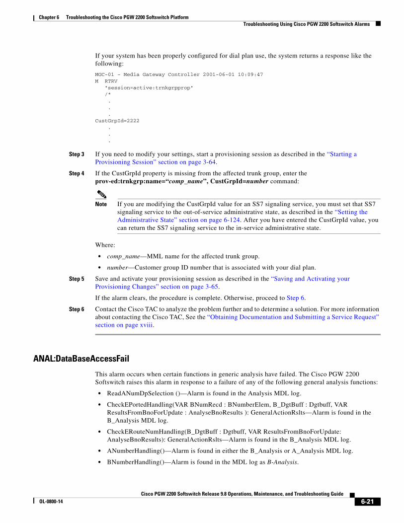
If your system has been properly configured for dial plan use, the system returns a response like the following:
MGC-01 - Media Gateway Controller 2001-06-01 10:09:47M RTRV "session=active:trnkgrpprop" /*
.
.
.CustGrpId=2222
.
.
.
Step 3 If you need to modify your settings, start a provisioning session as described in the “Starting a Provisioning Session” section on page 3-64.
Step 4 If the CustGrpId property is missing from the affected trunk group, enter the prov-ed:trnkgrp:name=“comp_name”, CustGrpId=number command:
Note If you are modifying the CustGrpId value for an SS7 signaling service, you must set that SS7 signaling service to the out-of-service administrative state, as described in the “Setting the Administrative State” section on page 6-124. After you have entered the CustGrpId value, you can return the SS7 signaling service to the in-service administrative state.
Where:
• comp_name—MML name for the affected trunk group.
• number—Customer group ID number that is associated with your dial plan.
Step 5 Save and activate your provisioning session as described in the “Saving and Activating your Provisioning Changes” section on page 3-65.
If the alarm clears, the procedure is complete. Otherwise, proceed to Step 6.
Step 6 Contact the Cisco TAC to analyze the problem further and to determine a solution. For more information about contacting the Cisco TAC, See the “Obtaining Documentation and Submitting a Service Request” section on page xviii.
ANAL:DataBaseAccessFail
This alarm occurs when certain functions in generic analysis have failed. The Cisco PGW 2200 Softswitch raises this alarm in response to a failure of any of the following general analysis functions:
• ReadANumDpSelection ()—Alarm is found in the Analysis MDL log.
• CheckEPortedHandling(VAR BNumRecd : BNumberElem, B_DgtBuff : Dgtbuff, VAR ResultsFromBnoForUpdate : AnalyseBnoResults ): GeneralActionRslts—Alarm is found in the B_Analysis MDL log.
• CheckERouteNumHandling(B_DgtBuff : Dgtbuff, VAR ResultsFromBnoForUpdate: AnalyseBnoResults): GeneralActionRslts—Alarm is found in the B_Analysis MDL log.
• ANumberHandling()—Alarm is found in either the B_Analysis or A_Analysis MDL log.
• BNumberHandling()—Alarm is found in the MDL log as B-Analysis.
6-21Cisco PGW 2200 Softswitch Release 9.8 Operations, Maintenance, and Troubleshooting Guide
OL-0800-14

Chapter 6 Troubleshooting the Cisco PGW 2200 Softswitch PlatformTroubleshooting Using Cisco PGW 2200 Softswitch Alarms
Corrective Action
Step 1 To collect system data, see the method that is described in the “Collecting System Data for Cisco TAC” section on page 6-93.
Step 2 Verify that the parameter, engine.SysConnectDataAccess, is set to true in the XECfgParm.dat file on the active Cisco PGW 2200 Softswitch. If the setting is correct, proceed to Step 4. Otherwise, update the value of the parameter for each host, using the procedure in the “Rebooting Software to Modify Configuration Parameters” section on page 6-183.
If correcting the setting does not clear the alarm, proceed to Step 4.
Step 3 Perform a call trace, as described in the “Performing a Call Trace” section on page 6-156.
Step 4 Contact the Cisco TAC to analyze the problem further and to determine a solution. For more information about contacting the Cisco TAC, see the “Obtaining Documentation and Submitting a Service Request” section on page xviii.
ANAL: Data Failure Rcvd
This alarm occurs during analysis when the Cisco PGW 2200 Softswitch detects a data failure in the external routing engine.
Corrective Action
To correct the problem, verify that the dial plan file was loaded correctly, using the procedure that is described in the “Verifying Proper Loading of a Dial Plan” section on page 6-121.
ANAL:dpselection_table_fail
This alarm occurs when the Cisco PGW 2200 Softswitch cannot find the correct dial plan selection.
Corrective Action
To correct the problem, verify that the dial plan file was loaded correctly, using the procedure that is described in the “Verifying Proper Loading of a Dial Plan” section on page 6-121.
ANAL:getDialplanBase_fail
This alarm occurs when the Cisco PGW 2200 Softswitch could not load or generate the dial plan.
Corrective Action
To correct the problem, verify that the dial plan file was loaded correctly, using the procedure that is described in the “Verifying Proper Loading of a Dial Plan” section on page 6-121.
ANAL: InvalidtrkGrpType
This alarm occurs when the analysis module has not provided a valid trunk group type. The problem occurs if the route analysis table specifies an invalid trunk group type.
6-22Cisco PGW 2200 Softswitch Release 9.8 Operations, Maintenance, and Troubleshooting Guide
OL-0800-14

Chapter 6 Troubleshooting the Cisco PGW 2200 Softswitch PlatformTroubleshooting Using Cisco PGW 2200 Softswitch Alarms
Corrective Action
To correct the problem, perform the following steps:
Step 1 To collect system data, see the method that is described in the “Collecting System Data for Cisco TAC” section on page 6-93.
Step 2 Display the valid trunk group types using the prov-rtrv MML command that is described in the “Retrieving Provisioning Data” section on page 3-69.
Step 3 Correct the invalid trunk group type in the route analysis table using the numan-ed MML command. See Cisco PGW 2200 Softswitch Release 9.8 Dial Plan Guide for more information. Save and activate your dial plan changes as described in the “Saving and Activating your Provisioning Changes” section on page 3-65.
If the alarm clears, the procedure is complete. Otherwise, proceed to Step 4.
Step 4 Contact the Cisco TAC to analyze the problem further and to determine a solution. For more information about contacting the Cisco TAC, see the “Obtaining Documentation and Submitting a Service Request” section on page xviii.
ANAL: Prof_GetFail_DigModTbl
This alarm occurs during profile analysis when a B-number modification result is encountered and the digit modification string is unreadable. This problem can occur if the digit modification table is corrupted or an incorrect digit modification index is stored in the B-number modification results data.
Corrective Action
To correct the problem, verify that the dial plan file was loaded correctly, using the procedure that is described in the “Verifying Proper Loading of a Dial Plan” section on page 6-121.
ANAL: Prof_GetFail_InvldRslt
This alarm occurs during profile analysis when the Cisco PGW 2200 Softswitch encounters a result that is not supported in profile analysis. Corruption of either the NOA or NPI tables, or the result table, causes this problem.
Corrective Action
To correct the problem, verify that the dial plan file was loaded correctly, using the procedure that is described in the “Verifying Proper Loading of a Dial Plan” section on page 6-121.
ANAL: Prof_GetFail_NOATbl
This alarm occurs during profile analysis when the NOA table is unreadable. This problem can occur if the NOA table is corrupted, the underlying software fails, or the NOA table is built without all the existing call context NOA values.
6-23Cisco PGW 2200 Softswitch Release 9.8 Operations, Maintenance, and Troubleshooting Guide
OL-0800-14

Chapter 6 Troubleshooting the Cisco PGW 2200 Softswitch PlatformTroubleshooting Using Cisco PGW 2200 Softswitch Alarms
Corrective Action
To correct the problem, perform the following steps:
Step 1 To collect system data, see the method that is described in the “Collecting System Data for Cisco TAC” section on page 6-93.
Step 2 Verify that the NOA table uses all of the existing call context NOA values using the numan-rtrv MML command. See Cisco PGW 2200 Softswitch Release 9.8 Dial Plan Guide for more information.
If the NOA table is missing any of the existing call context NOA values, add them using the numan-ed MML command. See Cisco PGW 2200 Softswitch Release 9.8 Dial Plan Guide for more information. Save and activate your dial plan changes as described in the “Saving and Activating your Provisioning Changes” section on page 3-65. Otherwise, proceed to Step 3.
Step 3 Verify that the dial plan file was loaded correctly, using the procedure that is described in the “Verifying Proper Loading of a Dial Plan” section on page 6-121.
ANAL: Prof_GetFail_NOATbl_A
This alarm occurs during profile analysis when the NOA table is unreadable. This problem can occur if the NOA table is corrupted or if the underlying software fails.
Corrective Action
To correct the problem, perform the following steps:
Step 1 To collect system data, see the method that is described in the “Collecting System Data for Cisco TAC” section on page 6-93.
Step 2 Perform a call trace, as described in the “Performing a Call Trace” section on page 6-156.
Step 3 Contact the Cisco TAC to analyze the problem further and to determine a solution. For more information about contacting the Cisco TAC, see the “Obtaining Documentation and Submitting a Service Request” section on page xviii.
ANAL: Prof_GetFail_NPITbl
This alarm occurs during profile analysis when the NPI table is unreadable. This problem can occur if the NPI table is corrupted, the underlying software fails, or the NPI table is not fully populated with all the possible references from the NOA table.
Corrective Action
To correct the problem, perform the following steps:
Step 1 To collect system data, see the method that is described in the “Collecting System Data for Cisco TAC” section on page 6-93.
6-24Cisco PGW 2200 Softswitch Release 9.8 Operations, Maintenance, and Troubleshooting Guide
OL-0800-14

Chapter 6 Troubleshooting the Cisco PGW 2200 Softswitch PlatformTroubleshooting Using Cisco PGW 2200 Softswitch Alarms
Step 2 Verify that the NPI table uses all of the possible references from the NOA table using the numan-rtrv MML command. See Cisco PGW 2200 Softswitch Release 9.8 Dial Plan Guide for more information.
If the NPI table is missing any of the references from the NOA table, add them using the numan-ed MML command. See Cisco PGW 2200 Softswitch Release 9.8 Dial Plan Guide for more information. Save and activate your dial plan changes as described in the “Saving and Activating your Provisioning Changes” section on page 3-65. Otherwise, proceed to Step 3.
Step 3 Verify that the dial plan file was loaded correctly, using the procedure that is described in the “Verifying Proper Loading of a Dial Plan” section on page 6-121.
ANAL: Prof_GetFail_NPITbl_A
This alarm occurs during profile analysis when the NPI table is unreadable. This problem can occur if the NOA table is corrupted, the underlying software fails.
Corrective Action
To correct the problem, perform the following steps:
Step 1 To collect system data, see the method that is described in the “Collecting System Data for Cisco TAC” section on page 6-93.
Step 2 Perform a call trace, as described in the “Performing a Call Trace” section on page 6-156.
Step 3 Contact the Cisco TAC to analyze the problem further and to determine a solution. For more information about contacting the Cisco TAC, see the “Obtaining Documentation and Submitting a Service Request” section on page xviii.
ANAL: Prof_GetFail_RsltTbl
This alarm occurs during profile analysis when the result table is unreadable. This problem can occur if the result table is corrupted, the underlying software fails, or the result table is not fully populated with all the possible references from the NOA or NPI tables.
Corrective Action
To correct the problem, perform the following steps:
Step 1 To collect system data, see the method that is described in the “Collecting System Data for Cisco TAC” section on page 6-93.
Step 2 Verify that the result table uses all of the possible references from the NOA and NPI tables using the numan-rtrv MML command. See Cisco PGW 2200 Softswitch Release 9.8 Dial Plan Guide for more information.
If the result table is missing any of the references from the NOA and NPI tables, add them using the numan-ed MML command. See Cisco PGW 2200 Softswitch Release 9.8 Dial Plan Guide for more information. Save and activate your dial plan changes as described in the “Saving and Activating your Provisioning Changes” section on page 3-65. Otherwise, proceed to Step 3.
6-25Cisco PGW 2200 Softswitch Release 9.8 Operations, Maintenance, and Troubleshooting Guide
OL-0800-14

Chapter 6 Troubleshooting the Cisco PGW 2200 Softswitch PlatformTroubleshooting Using Cisco PGW 2200 Softswitch Alarms
Step 3 Verify that the dial plan file was loaded correctly, by using the procedure that is described in the “Verifying Proper Loading of a Dial Plan” section on page 6-121.
ANAL: Prof_InvldNPAValue
This alarm occurs during profile analysis when the system encounters a 7-digit B-number and the NPA property is set against the originating trunk group. An NPA string of more or less than three characters is invalid. Data corruption is the most likely cause of this problem.
Corrective Action
To correct the problem, perform the following steps:
Step 1 To collect system data, see the method that is described in the “Collecting System Data for Cisco TAC” section on page 6-93.
Step 2 Verify that the NPA values have been properly provisioned for the trunk group by using the numan-rtrv MML command. See Cisco PGW 2200 Softswitch Release 9.8 Dial Plan Guide for more information.
If the NPA values are incorrect, modify them using the numan-ed MML command. See Cisco PGW 2200 Softswitch Release 9.8 Dial Plan Guide for more information. Save and activate your dial plan changes as described in the “Saving and Activating your Provisioning Changes” section on page 3-65. Otherwise, proceed to Step 3.
Step 3 Verify that the dial plan file was loaded correctly, using the procedure that is described in the “Verifying Proper Loading of a Dial Plan” section on page 6-121.
ANAL: Prof_InvRslts_NOATbl
This alarm occurs when profile analysis successfully reads the NOA table but the value that is returned is logically invalid. Profile analysis gets two values from the NOA table: an immediate result index and an NPI index. An immediate result index indicates that analysis should start reading results now, but an NPI index indicates that another table read is required to find the correct result table index. These results are logically incompatible. Most likely this results from a failure of the underlying software or a corruption of the NOA table.
Corrective Action
To correct the problem, verify that the dial plan file was loaded correctly, using the procedure that is described in the “Verifying Proper Loading of a Dial Plan” section on page 6-121.
ANAL: Prof_InvRslts_NOATbl_A
This alarm occurs when profile analysis successfully reads the NOA table but the value that is returned is logically invalid. Profile analysis gets two values from the NOA table, an immediate result index and an NPI index. The immediate result index indicates that analysis should start reading results now but the NPI index indicates that another table read is required to find the correct result table index. These results are logically incompatible. Most likely, the system raises this alarm when it detects a failure of the underlying software or a corruption of the NOA table.
6-26Cisco PGW 2200 Softswitch Release 9.8 Operations, Maintenance, and Troubleshooting Guide
OL-0800-14

Chapter 6 Troubleshooting the Cisco PGW 2200 Softswitch PlatformTroubleshooting Using Cisco PGW 2200 Softswitch Alarms
Corrective Action
To correct the problem, perform the following steps:
Step 1 To collect system data, see the method that is described in the “Collecting System Data for Cisco TAC” section on page 6-93.
Step 2 Perform a call trace, as described in the “Performing a Call Trace” section on page 6-156.
Step 3 Contact the Cisco TAC to analyze the problem further and to determine a solution. For more information about contacting the Cisco TAC, see the “Obtaining Documentation and Submitting a Service Request” section on page xviii.
ANAL: Prof_MdfyBFail_AppPtInvld
This alarm occurs during profile analysis when the system encounters a B-number modification result and the specified application point (where digits are inserted) is beyond the end of the digit string. This problem can occur if an incorrect application point is specified in the result data, a result table is corrupted, or profile analysis values are incorrectly constructed.
Corrective Action
To correct the problem that this alarm identifies, perform the following steps:
Step 1 To collect system data, see the method that is described in the “Collecting System Data for Cisco TAC” section on page 6-93.
Step 2 Verify that the specified application points in the result data are correct, using the numan-rtrv MML command. See Cisco PGW 2200 Softswitch Release 9.8 Dial Plan Guide for more information.
If any of the application points are incorrect, modify their value by using the numan-ed MML command. See Cisco PGW 2200 Softswitch Release 9.8 Dial Plan Guide for more information. Save and activate your dial plan changes as described in the “Saving and Activating your Provisioning Changes” section on page 3-65. Otherwise, proceed to Step 3.
Step 3 Verify that the dial plan file was loaded correctly, by using the procedure that is described in the “Verifying Proper Loading of a Dial Plan” section on page 6-121.
ANAL: RteStartIndexInvalid
This alarm occurs when the start index for the route analysis table is invalid.
Corrective Action
To correct the problem, perform the following steps:
Step 1 To collect system data, see the method that is described in the “Collecting System Data for Cisco TAC” section on page 6-93.
6-27Cisco PGW 2200 Softswitch Release 9.8 Operations, Maintenance, and Troubleshooting Guide
OL-0800-14

Chapter 6 Troubleshooting the Cisco PGW 2200 Softswitch PlatformTroubleshooting Using Cisco PGW 2200 Softswitch Alarms
Step 2 Verify that the data for the provisioned route lists is correct by logging in to the active Cisco PGW 2200 Softswitch, starting an MML session, and entering the prov-rtrv:rtlist:“all” command:
Step 3 If the data for the route lists is incorrect, correct it by using the prov-ed MML command. Otherwise, proceed to Step 4. See the Cisco PGW 2200 Softswitch Release 9.8 Provisioning Guide for more information on provisioning route lists.
Step 4 Contact the Cisco TAC to analyze the problem further and to determine a solution. For more information about contacting the Cisco TAC, see the “Obtaining Documentation and Submitting a Service Request” section on page xviii.
ANAL: Rte_TableHopCtrExceeded
This alarm occurs when generic analysis fails because of an excessive number of routing table changes.
Corrective Action
To correct the problem, perform the following steps:
Step 1 To collect system data, see the method that is described in the “Collecting System Data for Cisco TAC” section on page 6-93.
Step 2 Test for a loop in the routing configuration by completing the following steps:
a. Export the routing configuration to a file, as described in the “Exporting Provisioning Data” section on page 3-76.
b. Import the routing configuration file that is created in Step 2a, as described in the “Importing Provisioning Data” section on page 3-75.
If the import fails, proceed to Step 3. Otherwise, proceed to Step 4.
Step 3 Perform a call trace, as described in the “Performing a Call Trace” section on page 6-156.
Step 4 Contact the Cisco TAC to analyze the problem further and to determine a solution. For more information about contacting the Cisco TAC, see the “Obtaining Documentation and Submitting a Service Request” section on page xviii.
ANAL: RteTableFail_GetRteList
This alarm occurs when access to the route list failed. The problem occurs if the index to the route list is not valid or if the route list is not loaded.
Corrective Action
To correct the problem, verify that the dial plan file was loaded correctly, using the procedure that is described in the “Verifying Proper Loading of a Dial Plan” section on page 6-121.
6-28Cisco PGW 2200 Softswitch Release 9.8 Operations, Maintenance, and Troubleshooting Guide
OL-0800-14

Chapter 6 Troubleshooting the Cisco PGW 2200 Softswitch PlatformTroubleshooting Using Cisco PGW 2200 Softswitch Alarms
ANAL: RteTableFail_GetTrkAttrdata
This alarm occurs when access to the trunk group attribute data table failed. The problem occurs if the index to the trunk group attribute data table is not valid or if the table is not loaded.
Corrective Action
To correct the problem, verify that the dial plan file was loaded correctly, using the procedure that is described in the “Verifying Proper Loading of a Dial Plan” section on page 6-121.
ANAL: RteTableFail_GetTrkGrpdata
This alarm occurs when access to the trunk group data failed. The problem occurs if the index to the trunk group data is not valid or if the trunk group data table is not loaded.
Corrective Action
To correct the problem, verify that the dial plan file was loaded correctly. Use the procedure described in the “Verifying Proper Loading of a Dial Plan” section on page 6-121.
ANAL: RteTableFail_GetTrunkList
This alarm occurs when access to the trunk group list failed. The problem occurs if the index to the trunk group list is not valid or if the trunk group list is not loaded.
Corrective Action
To correct the problem, verify that the dial plan file was loaded correctly. Use the procedure described in the“Verifying Proper Loading of a Dial Plan” section on page 6-121.
ANAL: TableFail_BearerCapTable
This alarm occurs when the bearer capability table could not be read during generic analysis.
Corrective Action
To correct the problem, perform the following steps:
Step 1 To collect system data, see the method that is described in the “Collecting System Data for Cisco TAC” section on page 6-93.
Step 2 Perform a call trace, as described in the “Performing a Call Trace” section on page 6-156.
Step 3 Contact the Cisco TAC to analyze the problem further and to determine a solution. For more information about contacting the Cisco TAC, see the “Obtaining Documentation and Submitting a Service Request” section on page xviii.
6-29Cisco PGW 2200 Softswitch Release 9.8 Operations, Maintenance, and Troubleshooting Guide
OL-0800-14

Chapter 6 Troubleshooting the Cisco PGW 2200 Softswitch PlatformTroubleshooting Using Cisco PGW 2200 Softswitch Alarms
ANAL: TableFail_CondRouteDescTable
This alarm occurs when the conditional route description table could not be read during generic analysis.
Corrective Action
To correct the problem, perform the following steps:
Step 1 To collect system data, see the method that is described in the “Collecting System Data for Cisco TAC” section on page 6-93.
Step 2 Perform a call trace, as described in the “Performing a Call Trace” section on page 6-156.
Step 3 Contact the Cisco TAC to analyze the problem further and to determine a solution. For more information about contacting the Cisco TAC, see the “Obtaining Documentation and Submitting a Service Request” section on page xviii.
ANAL: TableFail_CondRouteTable
This alarm occurs when the system could not read the conditional routing table during generic analysis.
Corrective Action
To correct the problem, perform the following steps:
Step 1 To collect system data, see the method that is described in the “Collecting System Data for Cisco TAC” section on page 6-93.
Step 2 Verify that the dial plan file was loaded correctly, using the procedure that is described in the “Verifying Proper Loading of a Dial Plan” section on page 6-121.
If that procedure resolves the problem, the procedure is finished. Otherwise, proceed to Step 3.
Step 3 Perform a call trace, as described in the “Performing a Call Trace” section on page 6-156.
Step 4 Contact the Cisco TAC to analyze the problem further and to determine a solution. For more information about contacting the Cisco TAC, see the “Obtaining Documentation and Submitting a Service Request” section on page xviii.
ANAL: TableFail_CPCTable
This alarm occurs when the calling party category (CPC) table could not be read during generic analysis.
Corrective Action
To correct the problem, perform the following steps:
Step 1 To collect system data, see the method that is described in the “Collecting System Data for Cisco TAC” section on page 6-93.
Step 2 Perform a call trace, as described in the “Performing a Call Trace” section on page 6-156.
6-30Cisco PGW 2200 Softswitch Release 9.8 Operations, Maintenance, and Troubleshooting Guide
OL-0800-14

Chapter 6 Troubleshooting the Cisco PGW 2200 Softswitch PlatformTroubleshooting Using Cisco PGW 2200 Softswitch Alarms
Step 3 Contact the Cisco TAC to analyze the problem further and to determine a solution. For more information about contacting the Cisco TAC, see the “Obtaining Documentation and Submitting a Service Request” section on page xviii.
ANAL: TableFail_RouteHolTable
This alarm occurs when route holiday table could not be read during generic analysis.
Corrective Action
To correct the problem, perform the following steps:
Step 1 To collect system data, see the method that is described in the “Collecting System Data for Cisco TAC” section on page 6-93.
Step 2 Perform a call trace, as described in the “Performing a Call Trace” section on page 6-156.
Step 3 Contact the Cisco TAC to analyze the problem further and to determine a solution. For more information about contacting the Cisco TAC, see the “Obtaining Documentation and Submitting a Service Request” section on page xviii.
ANAL: TableFail_PercRouteTable
This alarm occurs when the percentage route holiday table could not be read during generic analysis.
Corrective Action
To correct the problem, perform the following steps:
Step 1 To collect system data, see the method that is described in the “Collecting System Data for Cisco TAC” section on page 6-93.
Step 2 Perform a call trace, as described in the “Performing a Call Trace” section on page 6-156.
Step 3 Contact the Cisco TAC to analyze the problem further and to determine a solution. For more information about contacting the Cisco TAC, see the “Obtaining Documentation and Submitting a Service Request” section on page xviii.
ANAL: TableFail_TMRTable
This alarm occurs when the transmission medium requirements (TMR) table could not be read during generic analysis.
6-31Cisco PGW 2200 Softswitch Release 9.8 Operations, Maintenance, and Troubleshooting Guide
OL-0800-14

Chapter 6 Troubleshooting the Cisco PGW 2200 Softswitch PlatformTroubleshooting Using Cisco PGW 2200 Softswitch Alarms
Corrective Action
To correct the problem, perform the following steps:
Step 1 To collect system data, see the method that is described in the “Collecting System Data for Cisco TAC” section on page 6-93.
Step 2 Perform a call trace, as described in the “Performing a Call Trace” section on page 6-156.
Step 3 Contact the Cisco TAC to analyze the problem further and to determine a solution. For more information about contacting the Cisco TAC, see the “Obtaining Documentation and Submitting a Service Request” section on page xviii.
ANAL: TableFail_TNSTable
This alarm occurs when the system cannot read the transit network selection (TNS) table during generic analysis.
Corrective Action
To correct the problem, perform the following steps:
Step 1 To collect system data, see the method that is described in the “Collecting System Data for Cisco TAC” section on page 6-93.
Step 2 Perform a call trace, as described in the “Performing a Call Trace” section on page 6-156.
Step 3 Contact the Cisco TAC to analyze the problem further and to determine a solution. For more information about contacting the Cisco TAC, see the “Obtaining Documentation and Submitting a Service Request” section on page xviii.
ANAL: TrunkGrpRsltCtrExceeded
This alarm occurs when the analysis module provided the maximum number of candidate trunk groups allowed. The maximum number is 20. The purpose of the alarm is to limit the time spent searching for candidate trunk groups.
Corrective Action
To correct the problem, verify that the dial plan file was loaded correctly, by using the procedure that is described in the “Verifying Proper Loading of a Dial Plan” section on page 6-121.
Association Degraded
This alarm occurs when one of the destination addresses for an SCTP association fails, but the association is still in-service (IS).
6-32Cisco PGW 2200 Softswitch Release 9.8 Operations, Maintenance, and Troubleshooting Guide
OL-0800-14

Chapter 6 Troubleshooting the Cisco PGW 2200 Softswitch PlatformTroubleshooting Using Cisco PGW 2200 Softswitch Alarms
Corrective Action
To correct the problem, perform the procedure in the “Resolving an Association Alarm” section on page 6-122.
Association Fail
This alarm occurs when an SCTP association fails because of an IP connectivity failure or an out-of-service (OOS) destination.
Corrective Action
To correct the problem, perform the procedure in the “Resolving an Association Alarm” section on page 6-122.
C7LNK ALGNMT LOST
This alarm occurs when the MTP2 for the C7 link between a Cisco ITP-L and an associated APC loses alignment.
Corrective Action
To correct the problem, use the diagnostics on the affected Cisco ITP-L to determine why the link lost alignment. See the “Verifying the Link Alignment Status” section on page B-6.
C7DPC CONGESTION
This alarm occurs when a link in a signaling route towards a given DPC becomes congested or when a DPC is congested and has sent a congestion indication to the Cisco PGW 2200 Softswitch.
Corrective Action
To correct the problem, perform the following steps:
Step 1 To collect system data, see the method that is described in the “Collecting System Data for Cisco TAC” section on page 6-93.
Step 2 Verify the status of the links that are associated with the affected DPC, as described in the “Retrieving Service State of C7/SS7 Links or Linksets” section on page 3-45.
If none of the links are out-of-service, this alarm occurred because the DPC is congested. Corrective action is not necessary. Wait for the congestion condition to clear.
If any of the links are out-of-service, proceed to Step 3.
Step 3 Return the out-of-service links to service, as described in the “Setting the Service State of a C7/SS7 Link or Linkset” section on page 6-105.
If that does not resolve the problem, proceed to Step 4.
Step 4 Contact the Cisco TAC to analyze the problem further and to determine a solution. For more information about contacting the Cisco TAC, see the “Obtaining Documentation and Submitting a Service Request” section on page xviii.
6-33Cisco PGW 2200 Softswitch Release 9.8 Operations, Maintenance, and Troubleshooting Guide
OL-0800-14

Chapter 6 Troubleshooting the Cisco PGW 2200 Softswitch PlatformTroubleshooting Using Cisco PGW 2200 Softswitch Alarms
C7LNK CONGESTION
This alarm occurs when an SS7 MTP2 link becomes congested and it cannot receive any more messages.
Corrective Action
If this alarm occurs repeatedly, perform the following steps to correct the problem:
Step 1 To collect system data, see the method that is described in the “Collecting System Data for Cisco TAC” section on page 6-93.
Step 2 Reduce the amount of traffic from the far-end that is associated with the affected link.
If that clears the alarm, the procedure is complete. Otherwise, proceed to Step 3.
Step 3 Add additional links to the linkset associated with the affected link. See Cisco PGW 2200 Softswitch Release 9.8 Provisioning Guide for more information about adding links.
If that does not resolve the problem, proceed to Step 4.
Step 4 Contact the Cisco TAC to analyze the problem further and to determine a solution. For more information about contacting the Cisco TAC, see the “Obtaining Documentation and Submitting a Service Request” section on page xviii.
C7LNK INHIBIT
This alarm occurs when a C7 link has been inhibited for maintenance.
Corrective Action
To correct the problem, uninhibit the specified C7 link, as described in the “Setting the Service State of a C7/SS7 Link or Linkset” section on page 6-105, when the maintenance is complete.
C7SLTLnkCong
This alarm occurs when an SS7 link on a 4-link Cisco ITP-L is congested.
Corrective Action
If this alarm occurs repeatedly, perform the following steps to correct the problem:
Step 1 To collect system data, refer to the method that is described in the “Collecting System Data for Cisco TAC” section on page 6-93.
6-34Cisco PGW 2200 Softswitch Release 9.8 Operations, Maintenance, and Troubleshooting Guide
OL-0800-14

Chapter 6 Troubleshooting the Cisco PGW 2200 Softswitch PlatformTroubleshooting Using Cisco PGW 2200 Softswitch Alarms
Step 2 Reroute the SS7 traffic to other links to reduce the congestion. See Cisco PGW 2200 Softswitch Release 9.8 Provisioning Guide for more information about adding links.
If that does not resolve the problem, proceed to Step 3.
Step 3 Contact the Cisco TAC to analyze the problem further and to determine a solution. For more information about contacting the Cisco TAC, see the “Obtaining Documentation and Submitting a Service Request” section on page xviii.
Call Back Feature Insertion Failure
This alarm occurs when an attempt to insert a call-back feature entry in the main memory database fails. When this insertion fails, the call-back feature does not work.
Corrective Action
Contact the Cisco TAC to analyze the problem and determine a solution. For more information about contacting the Cisco TAC, see the “Obtaining Documentation and Submitting a Service Request” section on page xviii.
Call Back Feature Deletion Failure
This alarm occurs when an attempt to delete a call-back feature entry from the main memory database fails. When this deletion fails, the call-back feature does not work.
Corrective Action
Contact the Cisco TAC to analyze the problem and determine a solution. For more information about contacting the Cisco TAC, see the “Obtaining Documentation and Submitting a Service Request” section on page xviii.
Charge Table Access Failure
This alarm occurs when the Cisco PGW 2200 Softswitch cannot access the charge table.
Corrective Action
To correct the problem, check for the presence of the Charge Table Load Failure alarm, using the procedure in the “Retrieving All Active Alarms” section on page 6-3. If this alarm is present, perform the corrective action for that alarm. Otherwise, the procedure is complete.
Charge Table Load Failure
This alarm occurs when a Cisco PGW 2200 Softswitch process is unable to load the charge table.
Corrective Action
Step 1 To collect system data, see the method that is described in the “Collecting System Data for Cisco TAC” section on page 6-93.
6-35Cisco PGW 2200 Softswitch Release 9.8 Operations, Maintenance, and Troubleshooting Guide
OL-0800-14

Chapter 6 Troubleshooting the Cisco PGW 2200 Softswitch PlatformTroubleshooting Using Cisco PGW 2200 Softswitch Alarms
Step 2 Verify whether a charge table is present on your system by logging in to your active Cisco PGW 2200 Softswitch, starting an MML session, and entering the prov-rtrv:charge:“all” command:
The system responds with a list of elements in the charge table, or with an error indicating that a charge table does not exist.
If a charge table is not present, provision a charge table, as described in Cisco PGW 2200 Softswitch Release 9.8 Dial Plan Guide.
If a charge table is present, verify that the information returned is correct. If the information is correct, proceed to Step 3. Otherwise, correct the contents of the charge table, as described in Cisco PGW 2200 Softswitch Release 9.8 Dial Plan Guide.
Step 3 Contact the Cisco TAC to analyze the problem further and to determine a solution. For more information about contacting the Cisco TAC, see the “Obtaining Documentation and Submitting a Service Request” section on page xviii.
Comm Srvc Creation Error
This alarm occurs when an error occurred while creating or opening a communication service.
Corrective Action
To correct the problem, perform the following steps:
Step 1 To collect system data, see the method that is described in the “Collecting System Data for Cisco TAC” section on page 6-93.
Step 2 Shut down the Cisco PGW 2200 Softswitch software on the standby Cisco PGW 2200 Softswitch, as described in the “Shutting Down the Cisco PGW 2200 Softswitch Software Manually” section on page 2-4.
Step 3 Restart the Cisco PGW 2200 Softswitch software on the standby Cisco PGW 2200 Softswitch, as described in the “Starting the Cisco PGW 2200 Softswitch Hardware” section on page 2-2.
Step 4 Perform a manual switchover operation, as described in the “Performing a Manual Switchover” section on page 3-96.
Caution Switchover operations cause the loss of all SS7 messages that are sent to the Cisco PGW 2200 Softswitch for approximately three seconds. The switchover affects unstable in-progress calls as well as new calls. Stable in-progress calls are not affected.
Step 5 Shut down the Cisco PGW 2200 Softswitch software on the newly standby Cisco PGW 2200 Softswitch, as described in the “Shutting Down the Cisco PGW 2200 Softswitch Software Manually” section on page 2-4.
Step 6 Restart the Cisco PGW 2200 Softswitch software on the newly standby Cisco PGW 2200 Softswitch, as described in the “Starting the Cisco PGW 2200 Softswitch Software” section on page 2-2.
Step 7 Perform a manual switchover operation, as described in the “Performing a Manual Switchover” section on page 3-96.
6-36Cisco PGW 2200 Softswitch Release 9.8 Operations, Maintenance, and Troubleshooting Guide
OL-0800-14
Chapter 6 Troubleshooting the Cisco PGW 2200 Softswitch PlatformTroubleshooting Using Cisco PGW 2200 Softswitch Alarms
Caution Switchover operations cause the loss of all SS7 messages that are sent to the Cisco PGW 2200 Softswitch for approximately 3 seconds. This switchover affects unstable in-progress calls as well as new calls. Stable in-progress calls are not affected.
If the switchover does not resolve the alarm, proceed to Step 8.
Step 8 Contact the Cisco TAC to analyze the problem further and to determine a solution. For more information about contacting the Cisco TAC, see the “Obtaining Documentation and Submitting a Service Request” section on page xviii.
Config Fail
This alarm occurs when the configuration has failed.
Corrective Action
To correct the problem, perform the following steps:
Step 1 To collect system data, see the method that is described in the “Collecting System Data for Cisco TAC” section on page 6-93.
Step 2 Search the active system log file, as described in the “Viewing System Logs” section on page 6-90, for logs that indicate errors in the content of the provisioning data.
If there are no logs that indicate errors in the content of the provisioning data, proceed to Step 3.
If there are logs that indicate errors in the content of the provisioning data, start a dynamic reconfiguration session to change the settings for the components that are identified in the log messages. See the “Invoking Dynamic Reconfiguration” section on page 3-66.
If changing component settings corrects the problem, the procedure is complete. Otherwise, proceed to Step 3.
Step 3 Contact the Cisco TAC to analyze the problem further and to determine a solution. For more information about contacting the Cisco TAC, see the “Obtaining Documentation and Submitting a Service Request” section on page xviii.
CTI Connection Failed
This alarm occurs when the CTI connection to the Cisco CallManager cluster has failed.
Corrective Action
To correct the problem, perform the following steps:
Step 1 Collect diagnostic information from your system.
6-37Cisco PGW 2200 Softswitch Release 9.8 Operations, Maintenance, and Troubleshooting Guide
OL-0800-14

Chapter 6 Troubleshooting the Cisco PGW 2200 Softswitch PlatformTroubleshooting Using Cisco PGW 2200 Softswitch Alarms
Step 2 Verify that the Ethernet interfaces between the Cisco PGW 2200 Softswitch and the Cisco CallManager cluster are working properly.
Determine the status of the Ethernet interfaces on the Cisco PGW 2200 Softswitch by using the Cisco IPT Platform Administration application. See the online Help topic for this subject for more information. You can find information on verifying the proper functioning of an Ethernet interface on the Cisco CallManager cluster in the associated documentation.
If the Ethernet connections are working correctly, proceed to Step 4. Otherwise, proceed to Step 3.
Step 3 If an element of the Ethernet connection (such as a cable or an Ethernet interface card) is not working properly, replace it. After the replacement is complete, return to Step 2.
Find information on removing and replacing an Ethernet interface card on either platform in the documentation that came with the platform.
Step 4 Verify that the MGCP sessions are operating normally. See the documentation for the affected media gateway for more information on verifying the functioning of the MGCP sessions.
If the MGCP sessions are not operating normally, return the MGCP sessions to normal operations, as described in the documentation for the affected Cisco CallManager cluster. Otherwise, proceed to Step 5.
Step 5 Contact the Cisco TAC to analyze the problem further and to determine a solution. For more information about contacting the Cisco TAC, see the “Obtaining Documentation and Submitting a Service Request” section on page xviii.
CTI Version Mismatch
This alarm occurs when the CTI version of the CTI Manager component that is configured on Cisco PGW 2200 Softswitch is not compatible with the version on the CTI Manager.
Corrective Action
Check the version of CTI Manager and install appropriate patches on the Cisco PGW 2200 Softswitch to make it compatible with the version on CTI Manager.
Dial Plan Loading Failed
This alarm occurs when a dial plan did not load properly.
Corrective Action
To correct the problem, verify that the dial plan file loaded correctly. Use the procedure that is described in the “Verifying Proper Loading of a Dial Plan” section on page 6-121.
DISK
This alarm occurs when the system disk is running out of space.
Corrective Action
To correct the problem, delete any unnecessary files from the Cisco PGW 2200 Softswitch, as described in the “Deleting Unnecessary Files to Increase Available Disk Space” section on page 6-169.
6-38Cisco PGW 2200 Softswitch Release 9.8 Operations, Maintenance, and Troubleshooting Guide
OL-0800-14

Chapter 6 Troubleshooting the Cisco PGW 2200 Softswitch PlatformTroubleshooting Using Cisco PGW 2200 Softswitch Alarms
EISUP: Unexpected Msg/Par
This alarm occurs when the EISUP module receives an unsupported message or parameter. This alarm is most likely to occur when the local EISUP version is older than the EISUP version used by the Cisco PGW 2200 Softswitch or the Cisco H.323 Signaling Interface (HSI) on the other end.
Corrective Action
To correct the problem, perform the following steps:
Step 1 To collect system data, see the method that is described in the “Collecting System Data for Cisco TAC” section on page 6-93.
Step 2 To upgrade the version of EISUP locally, you must either upgrade the Cisco PGW 2200 Softswitch software to the same release as the other Cisco PGW 2200 Softswitch, or to the release supported by your current version of the Cisco HSI software.
The steps that are required to upgrade the Cisco PGW 2200 Softswitch software are in Cisco PGW 2200 Softswitch Release 9 Software Installation and Configuration Guide.
If upgrading the Cisco PGW 2200 Softswitch software clears the alarm, the procedure is complete. Otherwise, proceed to Step 3.
Step 3 Contact the Cisco TAC to analyze the problem further and to determine a solution. For more information about contacting the Cisco TAC, see the “Obtaining Documentation and Submitting a Service Request” section on page xviii.
ENGINE CONFIG FAIL
This alarm occurs when a component in the engine configuration fails.
Corrective Action
To correct the problem, perform the following steps:
Step 1 To collect system data, see the method that is described in the “Collecting System Data for Cisco TAC” section on page 6-93.
Step 2 Search the active system log file for log messages indicating which component is raising this alarm. Use the procedure that is described in the “Viewing System Logs” section on page 6-90.
If there are logs that indicate a failed component, proceed to Step 3.
If there are no logs that indicate a failed component, proceed to Step 4.
Step 3 Begin a dynamic reconfiguration session to reprovision the failed component. Use the procedure that is described in the “Invoking Dynamic Reconfiguration” section on page 3-66.
If that resolves the problem, the procedure is complete. Otherwise, proceed to Step 4.
Step 4 Contact the Cisco TAC to analyze the problem further and to determine a solution. For more information about contacting the Cisco TAC, see the “Obtaining Documentation and Submitting a Service Request” section on page xviii.
6-39Cisco PGW 2200 Softswitch Release 9.8 Operations, Maintenance, and Troubleshooting Guide
OL-0800-14

Chapter 6 Troubleshooting the Cisco PGW 2200 Softswitch PlatformTroubleshooting Using Cisco PGW 2200 Softswitch Alarms
FAIL
This alarm occurs when the component referenced in the alarm failed. The failure might affect service, in which case, the system raises other alarms.
Corrective Action
To correct the problem, perform the following steps:
Step 1 To collect system data, see the method that is described in the “Collecting System Data for Cisco TAC” section on page 6-93.
Step 2 If the component identified in the alarm text is in the system software, contact the Cisco TAC to analyze the problem further and to determine a solution. For more information about contacting the Cisco TAC, see the “Obtaining Documentation and Submitting a Service Request” section on page xviii.
If the component identified in the alarm text is a component of system hardware, proceed to Step 3.
Step 3 Shut down the Cisco PGW 2200 Softswitch software on your standby Cisco PGW 2200 Softswitch, as described in the “Shutting Down the Cisco PGW 2200 Softswitch Software Manually” section on page 2-4.
Step 4 Restart the Cisco PGW 2200 Softswitch software on your standby Cisco PGW 2200 Softswitch, as described in the “Starting the Cisco PGW 2200 Softswitch Software” section on page 2-2.
Step 5 Perform a manual switchover, as described in the “Performing a Manual Switchover” section on page 3-96.
Caution Switchover operations cause the loss of all SS7 messages that are sent to the Cisco PGW 2200 Softswitch for approximately three seconds. The switchover affects unstable in-progress calls as well as new calls. Stable in-progress calls are not affected.
Step 6 Shut down the Cisco PGW 2200 Softswitch software on the newly standby Cisco PGW 2200 Softswitch, as described in the “Shutting Down the Cisco PGW 2200 Softswitch Software Manually” section on page 2-4.
Step 7 Restart the Cisco PGW 2200 Softswitch software on the newly standby Cisco PGW 2200 Softswitch, as described in the “Starting the Cisco PGW 2200 Softswitch Software” section on page 2-2.
If that resolves the problem, the procedure is complete. Otherwise, proceed to Step 8.
Step 8 Replace the component that is identified in the alarm text. You can find procedures for replacing Cisco PGW 2200 Softswitch hardware in the associated Sun Microsystems documentation. For procedures to replace Cisco ITP-L hardware, see the documentation for the Cisco 2800 Series Integrated Services Routers. Find procedures for replacing Cisco switch hardware in the documentation for the switch.
Step 9 Contact the Cisco TAC to analyze the problem further and to determine a solution. See the “Obtaining Documentation and Submitting a Service Request” section on page xviii.
6-40Cisco PGW 2200 Softswitch Release 9.8 Operations, Maintenance, and Troubleshooting Guide
OL-0800-14

Chapter 6 Troubleshooting the Cisco PGW 2200 Softswitch PlatformTroubleshooting Using Cisco PGW 2200 Softswitch Alarms
FailoverPeerLost
This alarm occurs when the failover daemon on the standby Cisco PGW 2200 Softswitch is not reachable.
Corrective Action
To correct the problem, perform the following steps:
Step 1 To collect system data, see the method that is described in the “Collecting System Data for Cisco TAC” section on page 6-93.
Step 2 Verify that the Ethernet interfaces between the active and standby Cisco PGW 2200 Softswitches and the Cisco switches are working properly.
Note For information on verifying the proper operation of an Ethernet interface on the Cisco PGW 2200 Softswitch, see the Sun Microsystems documentation that came with your system. For information on verifying the proper functioning of an Ethernet interface on the Cisco switches, see the documentation for your switch.
If an element of the Ethernet connection (such as a cable or an Ethernet interface card) is not working properly, replace it. Otherwise, proceed to Step 3.
Note For information on removing and replacing an Ethernet interface card on the Cisco PGW 2200 Softswitch, see the Sun Microsystems documentation that came with your system. For information on removing and replacing an Ethernet interface card on the Cisco switch, see the documentation for your switch.
Step 3 Contact the Cisco TAC to analyze the problem further and to determine a solution. For more information about contacting the Cisco TAC, see the “Obtaining Documentation and Submitting a Service Request” section on page xviii.
FailoverPeerOOS
This alarm occurs when the failover daemon goes out-of-service in the standby Cisco PGW 2200 Softswitch.
Corrective Action
To correct the problem, check the alarms on the standby Cisco PGW 2200 Softswitch. Use the procedure in the “Retrieving All Active Alarms” section on page 6-3, and resolve those alarms.
6-41Cisco PGW 2200 Softswitch Release 9.8 Operations, Maintenance, and Troubleshooting Guide
OL-0800-14

Chapter 6 Troubleshooting the Cisco PGW 2200 Softswitch PlatformTroubleshooting Using Cisco PGW 2200 Softswitch Alarms
FAIL REMOTE STANDBY
This alarm occurs on the active Cisco PGW 2200 Softswitch when a synchronization operation between the active and standby Cisco PGW 2200 Softswitches fails. The system automatically clears this alarm if a synchronization operation succeeds after the failure. If the synchronization succeeds, the system triggers the Standby Warm Start alarm. See the “Standby Warm Start” section on page 6-75 for more information.
Corrective Action
To correct the problem, perform the following steps:
Step 1 To collect system data, see the method that is described in the “Collecting System Data for Cisco TAC” section on page 6-93.
Step 2 Verify that the standby Cisco PGW 2200 Softswitch is in the standby platform state. Use the procedure that is defined in the “Verifying the Platform State of the Cisco PGW 2200 Softswitches” section on page 3-2.
If the standby Cisco PGW 2200 Softswitch is in the standby platform state, proceed to Step 3. Otherwise, proceed to Step 4.
Step 3 Synchronize the standby Cisco PGW 2200 Softswitch with the active Cisco PGW 2200 Softswitch by entering the prov-sync MML command.
Step 4 Shut down the Cisco PGW 2200 Softswitch software on your standby Cisco PGW 2200 Softswitch, as described in the “Shutting Down the Cisco PGW 2200 Softswitch Software Manually” section on page 2-4.
Step 5 Restart the Cisco PGW 2200 Softswitch software on your standby Cisco PGW 2200 Softswitch, as described in the “Starting the Cisco PGW 2200 Softswitch Software” section on page 2-2.
If that resolves the problem, the procedure is complete. Otherwise, proceed to Step 6.
Step 6 Contact the Cisco TAC to analyze the problem further and to determine a solution. For more information about contacting the Cisco TAC, see the “Obtaining Documentation and Submitting a Service Request” section on page xviii.
FORCE NODE RESTART
This alarm occurs on the standby Cisco PGW 2200 Softswitch when a new SS7 IOCC is added to the configuration of the system. This alarm causes the Cisco PGW 2200 Softswitch software on the standby Cisco PGW 2200 Softswitch to be rebooted. This alarm does not affect the active Cisco PGW 2200 Softswitch.
Corrective Action
To correct the problem, perform the following steps:
Step 1 When the Cisco PGW 2200 Softswitch software has restarted on the standby Cisco PGW 2200 Softswitch, collect system data. Refer to the method that is described in the “Collecting System Data for Cisco TAC” section on page 6-93.
6-42Cisco PGW 2200 Softswitch Release 9.8 Operations, Maintenance, and Troubleshooting Guide
OL-0800-14

Chapter 6 Troubleshooting the Cisco PGW 2200 Softswitch PlatformTroubleshooting Using Cisco PGW 2200 Softswitch Alarms
Step 2 Verify that the standby Cisco PGW 2200 Softswitch is in the standby platform state, using the procedure that is defined in the “Verifying the Platform State of the Cisco PGW 2200 Softswitches” section on page 3-2.
If the standby Cisco PGW 2200 Softswitch is in the standby platform state, the procedure is complete. Otherwise, proceed to Step 3.
Step 3 Contact the Cisco TAC to analyze the problem further and to determine a solution. For more information about contacting the Cisco TAC, see the “Obtaining Documentation and Submitting a Service Request” section on page xviii.
Gen Fail
This alarm occurs when a failure occurs because of resource exhaustion or configuration problems, such as the following:
• Memory exhaustion
• Queue overflow
• Message congestion
• IPC file cannot be opened
• Expired timer
Log messages in the active system log file indicate the nature of the failure. For the majority of the failures, this alarm is informational and no user action is required. If the system generates this alarm because it cannot open an IPC file, you must take corrective action.
Corrective Action
To correct the problem, perform the following steps:
Step 1 To collect system data, see the method that is described in the “Collecting System Data for Cisco TAC” section on page 6-93.
Step 2 Search the active system log file, as described in the “Viewing System Logs” section on page 6-90, for logs that indicate that an IPC file cannot be opened.
If there are no logs that indicate that an IPC file cannot be opened, no further action is required.
If there are logs that indicate that an IPC file cannot be opened, proceed to Step 3.
Step 3 Shut down the Cisco PGW 2200 Softswitch software on the standby Cisco PGW 2200 Softswitch, as described in the “Shutting Down the Cisco PGW 2200 Softswitch Software Manually” section on page 2-4.
Step 4 Restart the Cisco PGW 2200 Softswitch software on the standby Cisco PGW 2200 Softswitch, as described in the “Starting the Cisco PGW 2200 Softswitch Software” section on page 2-2.
Step 5 Perform a manual switchover, as described in the “Performing a Manual Switchover” section on page 3-96.
Caution Switchover operations cause the loss of all SS7 messages that are sent to the Cisco PGW 2200 Softswitch for approximately three seconds. The switchover affects unstable in-progress calls as well as new calls. Stable in-progress calls are not affected.
6-43Cisco PGW 2200 Softswitch Release 9.8 Operations, Maintenance, and Troubleshooting Guide
OL-0800-14

Chapter 6 Troubleshooting the Cisco PGW 2200 Softswitch PlatformTroubleshooting Using Cisco PGW 2200 Softswitch Alarms
Step 6 Shut down the Cisco PGW 2200 Softswitch software on your newly standby Cisco PGW 2200 Softswitch, as described in the “Shutting Down the Cisco PGW 2200 Softswitch Software Manually” section on page 2-4.
Step 7 Restart the Cisco PGW 2200 Softswitch software on your newly standby Cisco PGW 2200 Softswitch, as described in the “Starting the Cisco PGW 2200 Softswitch Software” section on page 2-2.
If that resolves the problem, the procedure is complete. Otherwise, proceed to Step 8.
Step 8 Contact the Cisco TAC to analyze the problem further and to determine a solution. For more information about contacting the Cisco TAC, see the “Obtaining Documentation and Submitting a Service Request” section on page xviii.
Holiday Table Access Failure
This alarm occurs when the Cisco PGW 2200 Softswitch cannot access the holiday table.
Corrective Action
To correct the problem, check for the presence of the Holiday Table Load Failure alarm, by using the procedure in the “Retrieving All Active Alarms” section on page 6-3. If this alarm is present, perform the corrective action for that alarm. Otherwise, the procedure is complete.
Holiday Table Load Failure
This alarm occurs when a Cisco PGW 2200 Softswitch process is unable to load the holiday table.
Corrective Action
Step 1 To collect system data, see the method that is described in the “Collecting System Data for Cisco TAC” section on page 6-93.
Step 2 Verify whether a holiday table is present on your system by logging in to the active Cisco PGW 2200 Softswitch, starting an MML session, and entering the prov-rtrv:holiday:“all” command:
The system responds with a list of elements in the holiday table, or with an error indicating that a holiday table does not exist.
If a holiday table is not present, provision a holiday table, as described in Cisco PGW 2200 Softswitch Release 9.8 Dial Plan Guide.
If a holiday table is present, verify that the information returned is correct. If the information is correct, proceed to Step 2. Otherwise, correct the contents of the holiday table, as described in Cisco PGW 2200 Softswitch Release 9.8 Dial Plan Guide.
Step 3 Contact the Cisco TAC to analyze the problem further and to determine a solution. For more information about contacting the Cisco TAC, see the “Obtaining Documentation and Submitting a Service Request” section on page xviii.
6-44Cisco PGW 2200 Softswitch Release 9.8 Operations, Maintenance, and Troubleshooting Guide
OL-0800-14

Chapter 6 Troubleshooting the Cisco PGW 2200 Softswitch PlatformTroubleshooting Using Cisco PGW 2200 Softswitch Alarms
INVALID M3UA RC
This alarm occurs when the Cisco PGW 2200 Softswitch receives an M3UA message from the identified Cisco ITP that includes a routing context that has not been provisioned on the Cisco PGW 2200 Softswitch.
Corrective Action
To correct the problem, perform the following steps:
Step 1 To collect system data, see the method that is described in the “Collecting System Data for Cisco TAC” section on page 6-93.
Step 2 Determine the AS definitions on the associated Cisco ITP. See the documentation for the Cisco ITP for more information.
Step 3 Retrieve the settings for the affected M3UA routing keys by using the prov-rtrv MML command, as described in the “Retrieving Provisioning Data” section on page 3-69.
Step 4 Identify the AS defined on the Cisco ITP that is not provisioned as a routing context on the Cisco PGW 2200 Softswitch.
Step 5 Open a dynamic reconfiguration session to add the routing context to the M3UA routing keys, as described in the “Invoking Dynamic Reconfiguration” section on page 3-66.
If adding the routing context to the M3UA routing keys corrects the problem, the procedure is complete. Otherwise, proceed to Step 6.
Step 6 Contact the Cisco TAC to analyze the problem further and to determine a solution. For more information about contacting the Cisco TAC, see the “Obtaining Documentation and Submitting a Service Request” section on page xviii.
INVALID SUA RC
This alarm occurs when the SUA routing keys that are defined on the Cisco PGW 2200 Softswitch do not match the SUA routing keys that are defined on the signaling gateway.
Corrective Action
To correct the problem, perform the following steps:
Step 1 To collect system data, see the method that is described in the “Collecting System Data for Cisco TAC” section on page 6-93.
Step 2 Determine the AS definitions on the associated Cisco ITP. See the documentation for your Cisco ITP for more information.
Step 3 Retrieve the settings for the affected SUA routing keys by using the prov-rtrv MML command, as described in the “Retrieving Provisioning Data” section on page 3-69.
Step 4 Identify the AS defined on the Cisco ITP that is not provisioned as a routing context on the Cisco PGW 2200 Softswitch.
6-45Cisco PGW 2200 Softswitch Release 9.8 Operations, Maintenance, and Troubleshooting Guide
OL-0800-14

Chapter 6 Troubleshooting the Cisco PGW 2200 Softswitch PlatformTroubleshooting Using Cisco PGW 2200 Softswitch Alarms
Step 5 Open a dynamic reconfiguration session to add the routing context to the SUA routing keys, as described in the “Invoking Dynamic Reconfiguration” section on page 3-66.
If adding the routing context corrects the problem, the procedure is complete. Otherwise, proceed to Step 6.
Step 6 Contact the Cisco TAC to analyze the problem further and to determine a solution. For more information about contacting the Cisco TAC, see the “Obtaining Documentation and Submitting a Service Request” section on page xviii.
Invalid Virtual_IP_Addr
This alarm occurs when the configured virtual IP address is not part of the networks that are associated with the IP addresses set for the IP_Addr1 or IP_Addr2 parameters in the XECfgParm.dat file.
Corrective Action
To correct the problem, perform the following steps:
Step 1 To collect system data, see the method that is described in the “Collecting System Data for Cisco TAC” section on page 6-93.
Step 2 Verify that the IP address defined for the XECfgParm.dat parameter, *.Virtual_IP_Addr, is set correctly in the XECfgParm.dat file on each host.
Note The IP address that is defined for this parameter should be a part of the networks that are associated with the IP addresses defined for the XECfgParm.dat parameters IP_Addr1 or IP_Addr2.
If the setting for the parameter is correct, proceed to Step 3. Otherwise, reboot your software using the procedure that is described in the “Rebooting Software to Modify Configuration Parameters” section on page 6-183.
Step 3 Contact the Cisco TAC to analyze the problem further and to determine a solution. For more information about contacting the Cisco TAC, see the “Obtaining Documentation and Submitting a Service Request” section on page xviii.
IP CONNECTION FAILED
This alarm occurs when the Cisco PGW 2200 Softswitch loses network (IP) connectivity to a Cisco ITP-L. The Cisco PGW 2200 Softswitch generates this alarm for each SS7 link that is associated with the affected Cisco ITP-L.
Corrective Action
To correct the problem, perform the following steps:
Step 1 To collect system data, see the method that is described in the “Collecting System Data for Cisco TAC” section on page 6-93.
6-46Cisco PGW 2200 Softswitch Release 9.8 Operations, Maintenance, and Troubleshooting Guide
OL-0800-14

Chapter 6 Troubleshooting the Cisco PGW 2200 Softswitch PlatformTroubleshooting Using Cisco PGW 2200 Softswitch Alarms
Step 2 Verify that the affected Cisco ITP-L is operating. See the documentation for the Cisco 2800 Series Integrated Services Routers.
If the affected Cisco ITP-L is not operating, start it using the procedure in the “Cisco SS7 Interface Startup Procedure” section on page 2-3. If starting the Cisco ITP-L does not resolve the problem, replace the affected Cisco ITP-L. See the documentation for the Cisco 2800 Series Integrated Services Routers.
If the affected Cisco ITP-L is operating, proceed to Step 3.
Step 3 Verify that the Ethernet interfaces between the Cisco PGW 2200 Softswitch and the affected Cisco ITP-L are working properly.
Note For information on verifying the proper operation of an Ethernet interface on the Cisco PGW 2200 Softswitch, see the Sun Microsystems documentation that came with your system. For information on verifying the proper functioning of an Ethernet interface on the Cisco ITP-L, see the documentation for the Cisco 2800 Series Integrated Services Routers.
If an element of the Ethernet connection (such as a cable or an Ethernet interface card) is not working properly, replace it. Otherwise, proceed to Step 4.
Note For information on removing and replacing an Ethernet interface card on the Cisco PGW 2200 Softswitch, see the Sun Microsystems documentation that came with your system. For information on removing and replacing components on the Cisco ITP-L, see the documentation for the Cisco 2800 Series Integrated Services Routers.
Step 4 Contact the Cisco TAC to analyze the problem further and to determine a solution. For more information about contacting the Cisco TAC, see the “Obtaining Documentation and Submitting a Service Request” section on page xviii.
IP RTE CONF FAIL
This alarm occurs when an IP route cannot access the local interface that its IP address parameter defined.
Corrective Action
To collect system data, see the method that is described in the “Collecting System Data for Cisco TAC” section on page 6-93. Contact the Cisco TAC to analyze the problem further and to determine a solution. For more information about contacting the Cisco TAC, see the “Obtaining Documentation and Submitting a Service Request” section on page xviii.
IP RTE FAIL
This alarm occurs when an IP route is in the OOS state with a cause other than off-duty or commanded out-of-service.
6-47Cisco PGW 2200 Softswitch Release 9.8 Operations, Maintenance, and Troubleshooting Guide
OL-0800-14

Chapter 6 Troubleshooting the Cisco PGW 2200 Softswitch PlatformTroubleshooting Using Cisco PGW 2200 Softswitch Alarms
Corrective Action
To correct the problem, perform the following steps:
Step 1 To collect system data, see the method that is described in the “Collecting System Data for Cisco TAC” section on page 6-93.
Step 2 Verify the IP addresses of the local interfaces on the standby Cisco PGW 2200 Softswitch by using the ifconfig -a UNIX command.
The system returns a response indicating the IP addresses of your local interfaces.
Step 3 Verify that the IP addresses obtained in Step 2 match the values that are set for the IP_Addr1 through IP_Addr4 parameters in the XECfgParm.dat file.
If the settings for the local IP addresses are not the same, proceed to Step 4.
If the settings for the local IP addresses are the same, proceed to Step 12.
Step 4 Log in to your active Cisco PGW 2200 Softswitch and change directories to the /opt/CiscoMGC/etc directory using the cd /opt/CiscoMGC/etc UNIX command:
Step 5 Open the XECfgParm.dat file in a text editor, such as vi.
Step 6 Search for the IP_Addr properties and change the properties that are not configured correctly.
Step 7 Save the file and exit the text editor.
Step 8 Shut down the Cisco PGW 2200 Softswitch software on the standby Cisco PGW 2200 Softswitch by entering the /etc/init.d/CiscoMGC stop UNIX command:
Note Shutting down the Cisco PGW 2200 Softswitch software on the active Cisco PGW 2200 Softswitch causes the currently standby Cisco PGW 2200 Softswitch to become the active Cisco PGW 2200 Softswitch.
Step 9 Restart the Cisco PGW 2200 Softswitch software on this Cisco PGW 2200 Softswitch by entering the /etc/init.d/CiscoMGC start command:
Step 10 When the Cisco PGW 2200 Softswitch software is fully activated, log in to the active Cisco PGW 2200 Softswitch and perform a manual switchover, using the sw-over::confirm MML command:
Step 11 Repeat Step 2 through Step 9 on the newly standby Cisco PGW 2200 Softswitch.
If the problem has not been resolved after you have completed those steps, proceed to Step 12.
Step 12 Contact the Cisco TAC to analyze the problem further and to determine a solution. For more information about contacting the Cisco TAC, see the “Obtaining Documentation and Submitting a Service Request” section on page xviii.
ISUP: COT Failure
This alarm occurs when the Cisco PGW 2200 Softswitch receives a COT message that indicates a failed continuity test.
6-48Cisco PGW 2200 Softswitch Release 9.8 Operations, Maintenance, and Troubleshooting Guide
OL-0800-14

Chapter 6 Troubleshooting the Cisco PGW 2200 Softswitch PlatformTroubleshooting Using Cisco PGW 2200 Softswitch Alarms
Corrective Action
To correct the problem, run a manual COT test, as described in the “Running a Manual Continuity Test” section on page 6-149.
License server unreachable
This alarm appears if the license server is unavailable. The Cisco PGW 2200 Softswitch looks at the local license files to retrieve the configuration time TDM ports/ the run time license information. Simultaneously, a timer starts.
If the license server is still unreachable after one week, the license number is half of the license number in license files.
If the license server is still unreachable after eight weeks, the license number is the number of demo licenses.
Corrective Action
If the license server unreachable alarm appears, use the rtrv-lics output to determine how many days license server has been unreachable.
Follow these steps to resolve this problem.
Step 1 Go to the machine where the license server is running (see the first line of the license file for the server hostname).
Step 2 Enter the ps -ef |grep lmgrd command to see whether the license server daemon is running.
a. If the license server is not running, enter the /opt/CiscoMGC/local/reload_lics.sh command to restart the license server.
b. If the license server still fails to start, check the /opt/CiscoMGC/var/log/flexlm_server.log for detailed information or contact Cisco TAC.
c. If the license server is running, but the active Cisco PGW 2200 Softswitch is running on a separate machine, ensure that the Cisco PGW 2200 Softswitch machine can reach the IP address of the license server machine.
LIF BER
This alarm occurs when the Cisco PGW 2200 Softswitch detects an excessive bit error ratio from a frame alignment signal. Any source of electrical noise might cause this alarm; for example, a degraded transmission line, degraded line connectors, or a high-voltage electrical source that is located in proximity to a line.
Corrective Action
To correct the problem, isolate the source by testing the connections and transmission line for the identified component. When you have identified the source, resolve as necessary.
6-49Cisco PGW 2200 Softswitch Release 9.8 Operations, Maintenance, and Troubleshooting Guide
OL-0800-14

Chapter 6 Troubleshooting the Cisco PGW 2200 Softswitch PlatformTroubleshooting Using Cisco PGW 2200 Softswitch Alarms
LIF FAIL
This alarm occurs when a local Ethernet interface fails.
Corrective Action
To correct the problem, perform the following steps:
Note If the Association Degraded or Association Failed alarms occur along with this alarm, follow the procedure that is defined in the “Resolving an Association Alarm” section on page 6-122.
Step 1 To collect system data, see the method that is described in the “Collecting System Data for Cisco TAC” section on page 6-93.
Step 2 Use the Log viewer in the MGC Viewer toolkit to search the system log file from the same time period as this alarm for a GEN_ERR_IPINTF_FAIL log message.
Note For more information on using the Log viewer, see Cisco PGW 2200 Softswitch Release 9 Operations, Maintenance, and Troubleshooting Guide.
If you detect a GEN_ERR_IPINTF_FAIL log message, proceed to Step 3. Otherwise, proceed to Step 7.
Step 3 Identify the cause of the failure from the information in the log message.
If the cause in the log message is “Admin Down,” the interface was taken down using an administrative command. Proceed to Step 4.
If the cause in the log message is “Link Down,” the Ethernet path failed. Proceed to Step 5.
Step 4 Enter the ifconfig interface up UNIX command to restore the link to service:
Where:
interface—IP address of the affected interface.
If the interface is restored and is working fine, the procedure is complete. Otherwise, proceed to Step 7.
Step 5 Verify that the cable connected between the interface and the associated Ethernet switch is working properly.
If the cable is working correctly, proceed to Step 6.
If the cable is not working correctly, replace it. If replacing the cable resolves the problem, the procedure is complete. Otherwise, proceed to Step 6.
Step 6 Verify that the associated Ethernet switch is working properly.
If the Ethernet switch is working correctly, proceed to Step 7.
If the Ethernet switch is not working correctly, troubleshoot the problem as indicated in the documentation for your switch. If that resolves the problem, the procedure is complete. Otherwise, proceed to Step 7.
Step 7 Contact the Cisco TAC to analyze the problem further and to determine a solution. For more information about contacting the Cisco TAC, see the “Obtaining Documentation and Submitting a Service Request” section on page xviii.
6-50Cisco PGW 2200 Softswitch Release 9.8 Operations, Maintenance, and Troubleshooting Guide
OL-0800-14
Chapter 6 Troubleshooting the Cisco PGW 2200 Softswitch PlatformTroubleshooting Using Cisco PGW 2200 Softswitch Alarms
LIF LOF
This alarm occurs when a loss of T1/E1 framing is detected on the LIF. The physical line has a signal but lost the framing pattern.
Corrective Action
To correct the problem, perform the following steps:
Step 1 To collect system data, see the method that is described in the “Collecting System Data for Cisco TAC” section on page 6-93.
Step 2 Verify that the framing format used on the port matches the framing format that is used on the line.
If the framing formats are different, change the framing format on the port to the other framing format. Otherwise, proceed to Step 3. If the alarm does not clear, proceed to Step 3.
Step 3 Change the line build-out setting. If the alarm does not clear, proceed to Step 4.
Step 4 Open the statistics report for the port and look for evidence of a bad line. Bursts of Latvia could indicate a timing problem.
If you find evidence of a bad line, perform loopback tests on the line to isolate the problem. Otherwise, proceed to Step 5. Once you have isolated the problem, resolve as necessary. If the alarm does not clear, proceed to Step 5.
Step 5 Contact the Cisco TAC to analyze the problem further and to determine a solution. For more information about contacting the Cisco TAC, see the “Obtaining Documentation and Submitting a Service Request” section on page xviii.
LIF LOS
This alarm occurs when the sent signal is lost in the T1/E1. The receiving end does not receive the signal. The physical line might have a break in it.
Corrective Action
To correct the problem, perform the following steps:
Step 1 To collect system data, see the method that is described in the “Collecting System Data for Cisco TAC” section on page 6-93.
Step 2 Verify that the cable connections are correct between the interface port and the service provider equipment or T1/E1 terminal equipment.
If the cable was built on-site, check the cable connectors. A reversal of send and receive pairs or an open receive pair can cause this condition.
If the cable connections appear correct, then proceed to Step 3.
Step 3 Check your T1/E1 equipment, or ask your service provider to test your T1/E1 line and correct any errors found.
If the alarm does not clear, then proceed to Step 4.
6-51Cisco PGW 2200 Softswitch Release 9.8 Operations, Maintenance, and Troubleshooting Guide
OL-0800-14

Chapter 6 Troubleshooting the Cisco PGW 2200 Softswitch PlatformTroubleshooting Using Cisco PGW 2200 Softswitch Alarms
Step 4 Contact the Cisco TAC to analyze the problem further and to determine a solution. For more information about contacting the Cisco TAC, see the “Obtaining Documentation and Submitting a Service Request” section on page xviii.
LIF SES
This alarm occurs when the LIF is automatically set to the out-of-service state because of severely errored seconds. The TDM line has a large amount of noise, causing an error rate greater than 10–3. Framing and signal are within tolerance. This alarm indicates a degraded but functioning line.
Corrective Action
To correct the problem, perform the following steps:
Step 1 To collect system data, see the method that is described in the “Collecting System Data for Cisco TAC” section on page 6-93.
Step 2 Verify that the terminations and cabling for the LIF are working. If you can identify the source of the problem, resolve as necessary. Otherwise, proceed to Step 3.
Step 3 Contact the Cisco TAC to analyze the problem further and to determine a solution. For more information about contacting the Cisco TAC, see the “Obtaining Documentation and Submitting a Service Request” section on page xviii.
LIF YELLOW
This alarm occurs when the receiving end reports a loss of the sent signal. This alarm is reported for T1/E1 facilities only.
Corrective Action
To correct the problem, perform the following steps:
Step 1 To collect system data, see the method that is described in the “Collecting System Data for Cisco TAC” section on page 6-93.
Step 2 Connect an external loopback cable to the affected port.
If no alarms are produced, proceed to Step 3.
If alarms are produced, the port is causing the error. Replace the hardware component that is associated with the port. See the associated media gateway documentation for more information on replacing the component.
Step 3 Check for an open, short, or wiring error in the cable between the network interface port and your service provider network interface unit T1/E1 terminal equipment. An open send pair can cause this condition.
If you find a wiring problem, replace the cable. If that does not clear the alarm, proceed to Step 4.
If you do not find a wiring problem, then proceed to Step 4.
6-52Cisco PGW 2200 Softswitch Release 9.8 Operations, Maintenance, and Troubleshooting Guide
OL-0800-14

Chapter 6 Troubleshooting the Cisco PGW 2200 Softswitch PlatformTroubleshooting Using Cisco PGW 2200 Softswitch Alarms
Step 4 If your port is configured to use D4 framing, the port might intermittently detect yellow alarms because the packet data might contain the pattern that is used to signal yellow alarm in D4 framing. If possible, switch to ESF framing in both the terminal equipment and the line equipment.
If switching the framing does not clear the alarm, proceed to Step 5.
Step 5 Contact the Cisco TAC to analyze the problem further and to determine a solution. For more information about contacting the Cisco TAC, see the “Obtaining Documentation and Submitting a Service Request” section on page xviii.
LIF: IDLE CHANGE
This alarm occurs when the physical line fails because its cable is broken or not plugged in. This alarm is reported for V.35 facilities only.
Corrective Action
To correct the problem, perform the following steps:
Step 1 To collect system data, see the method that is described in the “Collecting System Data for Cisco TAC” section on page 6-93.
Step 2 Verify that the V.35 cables between the port and the far-end are working correctly.
If you find a problem with a V.35 cable, replace the cable. If that does not correct the problem, proceed to Step 3.
If you do not find a problem with the V.35 cables, proceed to Step 3.
Step 3 Contact the Cisco TAC to analyze the problem further and to determine a solution. For more information about contacting the Cisco TAC, see the “Obtaining Documentation and Submitting a Service Request” section on page xviii.
LIF: LOST CD
This alarm occurs when the physical line has failed because its cable is broken or not plugged in. This is reported for V.35 facilities only.
Corrective Action
To correct the problem, perform the following steps:
Step 1 To collect system data, see the method that is described in the “Collecting System Data for Cisco TAC” section on page 6-93.
Step 2 Verify that the V.35 cables between the port and the far-end are working correctly.
If you find a problem with a V.35 cable, replace the cable. If that does not correct the problem, proceed to Step 3.
If you do not find a problem with the V.35 cables, proceed to Step 3.
6-53Cisco PGW 2200 Softswitch Release 9.8 Operations, Maintenance, and Troubleshooting Guide
OL-0800-14

Chapter 6 Troubleshooting the Cisco PGW 2200 Softswitch PlatformTroubleshooting Using Cisco PGW 2200 Softswitch Alarms
Step 3 Contact the Cisco TAC to analyze the problem further and to determine a solution. For more information about contacting the Cisco TAC, see the “Obtaining Documentation and Submitting a Service Request” section on page xviii.
LIF: LOST CTS
This alarm occurs when the physical line fails because its cable is broken or not plugged in. This is reported for V.35 facilities only.
Corrective Action
To correct the problem, perform the following steps:
Step 1 To collect system data, see the method that is described in the “Collecting System Data for Cisco TAC” section on page 6-93.
Step 2 Verify that the V.35 cables between the port and the far-end are working correctly.
If you find a problem with a V.35 cable, replace the cable. If that does not correct the problem, proceed to Step 3.
If you do not find a problem with the V.35 cables, proceed to Step 3.
Step 3 Contact the Cisco TAC to analyze the problem further and to determine a solution. For more information about contacting the Cisco TAC, see the “Obtaining Documentation and Submitting a Service Request” section on page xviii.
M3UAKEY Ack Pending
This alarm occurs when the Cisco PGW 2200 Softswitch cannot send or receive traffic for the identified SS7 signaling service via the Cisco ITP that has not acknowledged the M3UAKEY.
Corrective Action
To correct the problem, perform the following steps:
Step 1 To collect system data, see the method that is described in the “Collecting System Data for Cisco TAC” section on page 6-93.
Step 2 Determine the AS definitions on the associated Cisco ITP. See the documentation for your Cisco ITP for more information.
Step 3 Retrieve the settings for the affected M3UA routing keys using the prov-rtrv MML command, as described in the “Retrieving Provisioning Data” section on page 3-69.
Step 4 The AS definitions should match the routing contexts of the M3UA routing keys. If they match, proceed to Step 6. Otherwise, proceed to Step 5.
Step 5 Open a dynamic reconfiguration session to modify the routing contexts of the M3UA routing keys, as described in the “Invoking Dynamic Reconfiguration” section on page 3-66.
If modifying the routing contexts corrects the problem, the procedure is complete. Otherwise, proceed to Step 6.
6-54Cisco PGW 2200 Softswitch Release 9.8 Operations, Maintenance, and Troubleshooting Guide
OL-0800-14

Chapter 6 Troubleshooting the Cisco PGW 2200 Softswitch PlatformTroubleshooting Using Cisco PGW 2200 Softswitch Alarms
Step 6 Verify that the AS is not shut down on the Cisco ITP. See the documentation for your Cisco ITP for more information. If the AS is shut down, restart it. Otherwise, proceed to Step 7.
If restarting the AS corrects the problem, the procedure is complete. Otherwise, proceed to Step 7.
Step 7 Contact the Cisco TAC to analyze the problem further and to determine a solution. For more information about contacting the Cisco TAC, see the “Obtaining Documentation and Submitting a Service Request” section on page xviii.
Note If you modify an ss7path that is configured for M3UAKEY, the system generates the “All M3UAKEY Ack Pending“ alarm for all the other ss7paths that are configured with the same M3UAKEY, although they are not being modified.
Coincidentally, when you modify an ss7path, the system generates the M3UAKEY Ack Pending alarms when the prov-cpy and prov-dply commands are being processed. However, these alarms are cleared after the commands have been completed.
When the prov-cpy and prov-dply commands are being processed, no new calls can be placed on any of the ss7paths for which alarms were generated. However, the calls that already exist on the ss7paths are not affected.
MeterPulseTariff Table Load Failure
This alarm occurs when the Cisco PGW 2200 Softswitch fails to load the meter pulse tariff table.
Corrective Action
Step 1 To collect system data, see the method that is described in the “Collecting System Data for Cisco TAC” section on page 6-93.
Step 2 Verify whether a tariff table is present on your system by logging in to the active Cisco PGW 2200 Softswitch, starting an MML session, and entering the prov-rtrv:metertariff:“all” command:
The system responds with a list of elements in the meter pulse tariff table, or with an error message indicating that the meter pulse tariff table does not exist.
If the meter pulse tariff table is not present, provision a meter pulse tariff table, as described in Cisco PGW 2200 Softswitch Release 9.8 Dial Plan Guide.
If a meter pulse tariff table is present, verify that the information returned is correct. If the information is correct, proceed to Step 3. Otherwise, correct the contents of the meter pulse tariff table, as described in Cisco PGW 2200 Softswitch Release 9.8 Dial Plan Guide.
Step 3 Contact the Cisco TAC to analyze the problem further and to determine a solution. For more information about contacting the Cisco TAC, see the “Obtaining Documentation and Submitting a Service Request” section on page xviii.
6-55Cisco PGW 2200 Softswitch Release 9.8 Operations, Maintenance, and Troubleshooting Guide
OL-0800-14

Chapter 6 Troubleshooting the Cisco PGW 2200 Softswitch PlatformTroubleshooting Using Cisco PGW 2200 Softswitch Alarms
MMDB: Database unavailable
This alarm occurs when the main memory database is unavailable to provide any services. The Cisco PGW 2200 Softswitch attempts to recover. The alarm clears when the database becomes available.
Corrective Action
To correct the problem, delete any unnecessary files from the Cisco PGW 2200 Softswitch, as described in the “Deleting Unnecessary Files to Increase Available Disk Space” section on page 6-169.
MMDB: Database cause switchover
This alarm occurs when the main memory database is unavailable on a redundant system and is indicating that the system should switchover. The Cisco PGW 2200 Softswitch attempts to recover. The alarm clears when the database becomes available.
Corrective Action
To correct the problem, delete any unnecessary files from the standby Cisco PGW 2200 Softswitch, as described in the “Deleting Unnecessary Files to Increase Available Disk Space” section on page 6-169.
MMDB: Database nearly full
This alarm occurs when the main memory database detects that allocated resources for data storage are nearly all utilized.
Corrective Action
To correct the problem, delete any unnecessary files from the Cisco PGW 2200 Softswitch, as described in the “Deleting Unnecessary Files to Increase Available Disk Space” section on page 6-169.
NAS: AuditResponse Failure
This alarm occurs when the identified media gateway fails to send a RESYNC RESP message back to the Cisco PGW 2200 Softswitch within the audit time interval.
Corrective Action
To correct the problem, perform the following steps:
Step 1 To collect system data, see the method that is described in the “Collecting System Data for Cisco TAC” section on page 6-93.
Step 2 Verify that the affected media gateway is in the in-service state, as described in the “Verifying the Status of all Signaling Services” section on page 3-9.
If the affected media gateway is in-service, proceed to Step 3. Otherwise, proceed to Step 4.
Step 3 Verify that the configuration of the affected media gateway is correct. See the documentation for the media gateway for more information.
6-56Cisco PGW 2200 Softswitch Release 9.8 Operations, Maintenance, and Troubleshooting Guide
OL-0800-14

Chapter 6 Troubleshooting the Cisco PGW 2200 Softswitch PlatformTroubleshooting Using Cisco PGW 2200 Softswitch Alarms
If that does not resolve the problem, proceed to Step 4.
Step 4 Verify that the Ethernet interfaces between the Cisco PGW 2200 Softswitch and the associated media gateway are working properly.
Note For information on verifying the proper operation of an Ethernet interface on the Cisco PGW 2200 Softswitch, see the Sun Microsystems documentation that came with your system. For information on verifying the proper functioning of an Ethernet interface on the media gateway, see the documentation for the specific media gateway.
If an element of the Ethernet connection (such as a cable or an Ethernet interface card) is not working properly, replace it. Otherwise, proceed to Step 5.
Note For information on removing and replacing an Ethernet interface card on the Cisco PGW 2200 Softswitch, see the Sun Microsystems documentation that came with your system. For information on removing and replacing an Ethernet interface card on the media gateway, see the documentation for the specific media gateway.
Step 5 Contact the Cisco TAC to analyze the problem further and to determine a solution. For more information about contacting the Cisco TAC, see the “Obtaining Documentation and Submitting a Service Request” section on page xviii.
NAS: CommsFailure
This alarm occurs when the Cisco PGW 2200 Softswitch cannot communicate with the identified media gateway.
Corrective Action
To correct the problem, perform the following steps:
Step 1 To collect system data, see the method that is described in the “Collecting System Data for Cisco TAC” section on page 6-93.
Step 2 Determine whether the affected media gateway is operating. See the documentation for the media gateway for more information.
If the affected media gateway is not operating, restore it to service. See the documentation for the media gateway for more information.
If the affected media gateway is operating, proceed to Step 3.
Step 3 Verify that the IP configuration parameters for the Cisco PGW 2200 Softswitch and the affected media gateway are correct.
Note Use the prov-rtrv MML command, as described in the “Retrieving Provisioning Data” section on page 3-69, to retrieve the IP configuration information for the Cisco PGW 2200 Softswitch. See the documentation for the media gateway for information on retrieving the IP configuration data.
6-57Cisco PGW 2200 Softswitch Release 9.8 Operations, Maintenance, and Troubleshooting Guide
OL-0800-14

Chapter 6 Troubleshooting the Cisco PGW 2200 Softswitch PlatformTroubleshooting Using Cisco PGW 2200 Softswitch Alarms
If the configuration of the Cisco PGW 2200 Softswitch is incorrect, begin a dynamic reconfiguration session, as described in the “Invoking Dynamic Reconfiguration” section on page 3-66.
If the configuration of the affected media gateway is incorrect, modify the provisioning data for your system. See the documentation for the media gateway for more information.
If the configuration of both the Cisco PGW 2200 Softswitch and the affected media gateway are correct, then proceed to Step 4.
Step 4 Contact the Cisco TAC to analyze the problem further and to determine a solution. For more information about contacting the Cisco TAC, see the “Obtaining Documentation and Submitting a Service Request” section on page xviii.
NAS: ResourceFailure
This alarm occurs when the indicated media gateway does not acknowledge a continuity test (COT).
Corrective Action
To correct the problem, run a manual COT on the indicated media gateway, as described in the Running a Manual Continuity Test, page 6-149.
OLC: Leg1chanSeizedUnpackError
This alarm occurs when the Cisco PGW 2200 Softswitch receives a Seized Channel (CRCX) acknowledge message from the media gateway, which could not be unpacked.
Corrective Action
To correct the problem, perform the following steps:
Step 1 To collect system data, see the method that is described in the “Collecting System Data for Cisco TAC” section on page 6-93.
Step 2 Perform a call trace, as described in the “Performing a Call Trace” section on page 6-156.
Step 3 Contact the Cisco TAC to analyze the problem further and to determine a solution. For more information about contacting the Cisco TAC, see the “Obtaining Documentation and Submitting a Service Request” section on page xviii.
OLC: Leg1chanModifiedUnpackError
This alarm occurs when the Cisco PGW 2200 Softswitch receives a Modify Channel (MDCX) acknowledge message from the media gateway, which could not be unpacked.
Corrective Action
To correct the problem, perform the following steps:
6-58Cisco PGW 2200 Softswitch Release 9.8 Operations, Maintenance, and Troubleshooting Guide
OL-0800-14

Chapter 6 Troubleshooting the Cisco PGW 2200 Softswitch PlatformTroubleshooting Using Cisco PGW 2200 Softswitch Alarms
Step 1 To collect system data, see the method that is described in the “Collecting System Data for Cisco TAC” section on page 6-93.
Step 2 Perform a call trace, as described in the “Performing a Call Trace” section on page 6-156.
Step 3 Contact the Cisco TAC to analyze the problem further and to determine a solution. For more information about contacting the Cisco TAC, see the “Obtaining Documentation and Submitting a Service Request” section on page xviii.
OLC: Leg1chanDeletedUnpackError
This alarm occurs when the Cisco PGW 2200 Softswitch receives a Delete Channel (DLCX) acknowledge message from the media gateway, which could not be unpacked.
Corrective Action
To correct the problem, perform the following steps:
Step 1 To collect system data, see the method that is described in the “Collecting System Data for Cisco TAC” section on page 6-93.
Step 2 Perform a call trace, as described in the “Performing a Call Trace” section on page 6-156.
Step 3 Contact the Cisco TAC to analyze the problem further and to determine a solution. For more information about contacting the Cisco TAC, see the “Obtaining Documentation and Submitting a Service Request” section on page xviii.
OLC: Leg1notifyUnpackError
This alarm occurs when the Cisco PGW 2200 Softswitch receives a Notify (NTFY) message from the media gateway, which could not be unpacked.
Corrective Action
To correct the problem, perform the following steps:
Step 1 To collect system data, see the method that is described in the “Collecting System Data for Cisco TAC” section on page 6-93.
Step 2 Perform a call trace, as described in the “Performing a Call Trace” section on page 6-156.
Step 3 Contact the Cisco TAC to analyze the problem further and to determine a solution. For more information about contacting the Cisco TAC, see the “Obtaining Documentation and Submitting a Service Request” section on page xviii.
6-59Cisco PGW 2200 Softswitch Release 9.8 Operations, Maintenance, and Troubleshooting Guide
OL-0800-14

Chapter 6 Troubleshooting the Cisco PGW 2200 Softswitch PlatformTroubleshooting Using Cisco PGW 2200 Softswitch Alarms
OLC: Leg1deleteChanUnpackError
This alarm occurs when the Cisco PGW 2200 Softswitch receives a Delete Channel (DLCX) message from the media gateway, which could not be unpacked.
6-60Cisco PGW 2200 Softswitch Release 9.8 Operations, Maintenance, and Troubleshooting Guide
OL-0800-14
Chapter 6 Troubleshooting the Cisco PGW 2200 Softswitch PlatformTroubleshooting Using Cisco PGW 2200 Softswitch Alarms
Corrective Action
To correct the problem, perform the following steps:
Step 1 To collect system data, see the method that is described in the “Collecting System Data for Cisco TAC” section on page 6-93.
Step 2 Perform a call trace, as described in the “Performing a Call Trace” section on page 6-156.
Step 3 Contact the Cisco TAC to analyze the problem further and to determine a solution. For more information about contacting the Cisco TAC, see the “Obtaining Documentation and Submitting a Service Request” section on page xviii.
OLC: Leg1notifyRequestAckUnpackError
This alarm occurs when the Cisco PGW 2200 Softswitch receives a Request Notify (RQNT) acknowledge message from the media gateway, which could not be unpacked.
Corrective Action
To correct the problem, perform the following steps:
Step 1 To collect system data, see the method that is described in the “Collecting System Data for Cisco TAC” section on page 6-93.
Step 2 Perform a call trace, as described in the “Performing a Call Trace” section on page 6-156.
Step 3 Contact the Cisco TAC to analyze the problem further and to determine a solution. For more information about contacting the Cisco TAC, see the “Obtaining Documentation and Submitting a Service Request” section on page xviii.
OLC: Leg1chanOpsFailed
This alarm occurs when the Cisco PGW 2200 Softswitch detects an internal error or a problem that is related to a media gateway.
Corrective Action
To correct the problem, perform the following steps:
Step 1 To collect system data, see the method that is described in the “Collecting System Data for Cisco TAC” section on page 6-93.
Step 2 Perform a call trace, as described in the “Performing a Call Trace” section on page 6-156.
Step 3 Contact the Cisco TAC to analyze the problem further and to determine a solution. For more information about contacting the Cisco TAC, see the “Obtaining Documentation and Submitting a Service Request” section on page xviii.
6-61Cisco PGW 2200 Softswitch Release 9.8 Operations, Maintenance, and Troubleshooting Guide
OL-0800-14

Chapter 6 Troubleshooting the Cisco PGW 2200 Softswitch PlatformTroubleshooting Using Cisco PGW 2200 Softswitch Alarms
OOS TRAFFIC RE-ROUTE
This alarm occurs when the traffic channels (bearer channels, IP network) on one side of the Cisco PGW 2200 Softswitch are lost, which causes the Cisco PGW 2200 Softswitch to reroute channels away from the affected component. Usually, this alarm is generally because of a network or equipment failure, but might be because of a provisioning failure.
Corrective Action
To correct the problem, perform the following steps:
Step 1 To collect system data, see the method that is described in the “Collecting System Data for Cisco TAC” section on page 6-93.
Step 2 The Cisco PGW 2200 Softswitch should display the other alarms that are associated with the affected component. Resolve those alarms first.
If resolving those alarms does not clear this alarm, proceed to Step 3.
Step 3 Verify that the traffic channel settings that are provisioned for the Cisco PGW 2200 Softswitch and the affected media gateway are correct.
Note Use the prov-rtrv MML command, as described in the “Retrieving Provisioning Data” section on page 3-69, to retrieve the traffic channel provisioning data for the Cisco PGW 2200 Softswitch. See the documentation for the media gateway for information on retrieving the traffic channel data.
If the configuration of the Cisco PGW 2200 Softswitch is incorrect, begin a dynamic reconfiguration session, as described in the “Invoking Dynamic Reconfiguration” section on page 3-66.
If the configuration of the affected media gateway is incorrect, modify the provisioning data for your system. See the documentation for the media gateway for more information.
If the configuration of both the Cisco PGW 2200 Softswitch and the affected media gateway are correct, then proceed to Step 4.
Step 4 Contact the Cisco TAC to analyze the problem further and to determine a solution. For more information about contacting the Cisco TAC, see the “Obtaining Documentation and Submitting a Service Request” section on page xviii.
OverloadHeavy
This alarm occurs when the system reaches the threshold for overload level 3. The system performs an automatic switchover operation. If the call rejection percentage setting for overload level 3 is unchanged from its default value, the system rejects all new calls until the abate threshold for overload level 3 is reached. The system automatically clears the alarm at that time. For more information, see the “Managing Automatic Congestion Control” section on page 3-77.
6-62Cisco PGW 2200 Softswitch Release 9.8 Operations, Maintenance, and Troubleshooting Guide
OL-0800-14

Chapter 6 Troubleshooting the Cisco PGW 2200 Softswitch PlatformTroubleshooting Using Cisco PGW 2200 Softswitch Alarms
Corrective Action
If a rare spike in traffic causes this alarm, corrective action is not necessary. If this alarm occurs regularly, you should ensure that your links and routes are properly configured for load sharing, as described in the “SS7 Load Sharing Malfunction” section on page 6-97, and reroute some of your traffic to other Cisco PGW 2200 Softswitches.
Note This alarm can occur when a provisioning session is active during peak busy hours. If this alarm occurs during a provisioning session, you might clear the alarm by stopping the provisioning session. For more information on the MML commands to manage a provisioning session, see the “Provisioning a Cisco PGW 2200 Softswitch” section on page 3-64.
OverloadMedium
This alarm occurs when the system reaches the threshold for overload level 2. The system rejects a percentage of new calls that are based on the call rejection percentage setting for overload level 2, until the system reaches the abate threshold for overload level 2. The system automatically clears this alarm at that time. For more information, see the “Managing Automatic Congestion Control” section on page 3-77.
Corrective Action
If a a rare spike in traffic causes this alarm, corrective action is not necessary. If this alarm occurs regularly, you should ensure that your links and routes are properly configured for load sharing, as described in the “SS7 Load Sharing Malfunction” section on page 6-97, and reroute some of your traffic to other Cisco PGW 2200 Softswitches.
Note This alarm can occur when a provisioning session is active during peak busy hours. If a provisioning session is active, you can clear the alarm by stopping the provisioning session. For more information on the MML commands to manage a provisioning session, see the “Provisioning a Cisco PGW 2200 Softswitch” section on page 3-64.
OverloadLight
This alarm occurs when the system reaches the threshold for overload level 1. The system rejects a percentage of new calls that are based on the call rejection percentage setting for overload level 1, until the abate threshold for overload level 1 is reached. The system automatically clears this alarm at that time. For more information, see the “Managing Automatic Congestion Control” section on page 3-77.
Corrective Action
If a rare spike in traffic causes this alarm, corrective action is not necessary. If this alarm occurs regularly, you should ensure that your links and routes are properly configured for load sharing, as described in the “SS7 Load Sharing Malfunction” section on page 6-97, and reroute traffic to other Cisco PGW 2200 Softswitches.
6-63Cisco PGW 2200 Softswitch Release 9.8 Operations, Maintenance, and Troubleshooting Guide
OL-0800-14

Chapter 6 Troubleshooting the Cisco PGW 2200 Softswitch PlatformTroubleshooting Using Cisco PGW 2200 Softswitch Alarms
Note This alarm can occur when a provisioning session is active during peak busy hours. If a provisioning session is active, you might clear the alarm by stopping the provisioning session. For more information on the MML commands to manage a provisioning session, see the “Provisioning a Cisco PGW 2200 Softswitch” section on page 3-64.
OverResIncomingThreshold
This alarm occurs when the percentage of idle CICs in a trunk group is less than or equal to the configured threshold.
Corrective Action
This alarm might occur occasionally during periods of congestion. However, if this alarm occurs repeatedly, you might need to adjust the value of the parameter that controls the percentage of idle CICs for the affected trunk group. To modify the parameter, perform the following steps:
Step 1 To collect system data, see the method that is described in the “Collecting System Data for Cisco TAC” section on page 6-93.Retrieve the current settings for the affected trunk group using the prov-rtrv:rttrnkgrp:name=“trnkgrp_name” command:
Where:
trnkgrp_name is the name of the affected trunk group.
The system returns a response like the following:
MGC-01 - Media Gateway Controller 2002-09-20 15:38:02.892 ESTM RTRV "session=NOA_SPAIN:rttrnkgrp" /*name type reattempts queuing cutThrough resIncomingPerc---------- ---- ---------- ------- ---------- ----------111 1 2 120 2 0 */
The parameter, ResIncomingPerc, controls the percentage of idle CICs for the trunk group. In the preceding example, the value is 0.
Step 2 Start a provisioning session, as described in the “Starting a Provisioning Session” section on page 3-64.
Step 3 Use the prov-ed MML command to modify the setting of the resIncomingPerc parameter. For example, to change the percentage of idle CICs to 30 percent in a trunk group that is called 1000, enter the prov-ed:rttrnkgrp:name=“1000”, resImcomingPerc=“30” command:
Note The new value for resIncomingPerc takes effect after your provisioning session is activated. Once the new value is activated, the OverResIncomingThreshold alarm is set or cleared after an outgoing call is routed over the affected trunk group.
Step 4 Save and activate the provisioning session, as described in the “Saving and Activating your Provisioning Changes” section on page 3-65.
If the alarm clears, the procedure is complete. Otherwise, proceed to Step 5.
6-64Cisco PGW 2200 Softswitch Release 9.8 Operations, Maintenance, and Troubleshooting Guide
OL-0800-14

Chapter 6 Troubleshooting the Cisco PGW 2200 Softswitch PlatformTroubleshooting Using Cisco PGW 2200 Softswitch Alarms
Step 5 Contact the Cisco TAC to analyze the problem further and to determine a solution. For more information about contacting the Cisco TAC, see the “Obtaining Documentation and Submitting a Service Request” section on page xviii.
PC UNAVAIL
This alarm occurs when a destination point code (DPC) is unavailable. This alarm can occur if a network failure isolates the DPC; or, the alarm can occur if a local equipment failure causes a loss of connectivity. Also, the Cisco PGW 2200 Softswitch can raise the alarm if the DPC, or routes to the DPC, were configured improperly.
Corrective Action
To correct the problem, perform the following steps:
Step 1 To collect system data, see the method that is described in the “Collecting System Data for Cisco TAC” section on page 6-93.
Step 2 The Cisco PGW 2200 Softswitch should also display other alarms that indicate problems with hardware, the SS7 links, or the network. Resolve those alarms first.
If resolving those alarms does not clear this alarm, proceed to Step 3.
Step 3 Ensure that the provisioning settings for the DPC and for all routes to the DPC and adjacent STPs match the settings that are used on the far-end, as described in the “Retrieving Provisioning Data” section on page 3-69.
If the configuration data associated with the DPC is incorrect, begin a dynamic reconfiguration session, as described in the “Invoking Dynamic Reconfiguration” section on page 3-66.
If the configuration data associated with the DPC is correct, then proceed to Step 4.
Step 4 Contact the Cisco TAC to analyze the problem further and to determine a solution. For more information about contacting the Cisco TAC, see the “Obtaining Documentation and Submitting a Service Request” section on page xviii.
Peer IP Links Failure
This alarm occurs when the IP links to the peer Cisco PGW 2200 Softswitch are removed or down.
Corrective Action
To correct the problem, perform the following steps:
Step 1 To collect system data, see the method that is described in the “Collecting System Data for Cisco TAC” section on page 6-93.
Step 2 Verify that the Ethernet interfaces for the active and standby Cisco PGW 2200 Softswitches are working properly.
6-65Cisco PGW 2200 Softswitch Release 9.8 Operations, Maintenance, and Troubleshooting Guide
OL-0800-14

Chapter 6 Troubleshooting the Cisco PGW 2200 Softswitch PlatformTroubleshooting Using Cisco PGW 2200 Softswitch Alarms
Note You can find information on verifying the proper operation of an Ethernet interface on the Cisco PGW 2200 Softswitch in the Sun Microsystems documentation that came with your system.
If an element of the Ethernet connection (such as a cable or an Ethernet interface card) is not working properly, replace it. Otherwise, proceed to Step 3.
Note You can find information on removing and replacing an Ethernet interface card on the Cisco PGW 2200 Softswitch in the Sun Microsystems documentation that came with your system.
Step 3 Contact the Cisco TAC to analyze the problem further and to determine a solution. For more information about contacting the Cisco TAC, see the “Obtaining Documentation and Submitting a Service Request” section on page xviii.
PEER LINK A FAILURE
This alarm occurs either because a communication path between peer modules was lost or a peer module has stopped communicating.
Corrective Action
To correct the problem, perform the procedure in the “Resolving a Failed Connection to a Peer” section on page 6-181.
PEER LINK B FAILURE
This alarm occurs either because a communication path between peer modules was lost or a peer module has stopped communicating.
Corrective Action
To correct the problem, perform the procedure in the “Resolving a Failed Connection to a Peer” section on page 6-181.
PEER MODULE FAILURE
This alarm occurs when communications to a peer module are lost, indicating failure.
Corrective Action
To correct the problem, perform the procedure in the “Resolving a Failed Connection to a Peer” section on page 6-181.
POM INACTIVITY TIMEOUT
This alarm occurs when a provisioning session has been idle for 20 minutes. If there is no provisioning activity within the next 5 minutes, the system terminates the session.
6-66Cisco PGW 2200 Softswitch Release 9.8 Operations, Maintenance, and Troubleshooting Guide
OL-0800-14

Chapter 6 Troubleshooting the Cisco PGW 2200 Softswitch PlatformTroubleshooting Using Cisco PGW 2200 Softswitch Alarms
Corrective Action
To correct the problem, enter some provisioning MML commands, or stop the provisioning session as described in the “Saving and Activating your Provisioning Changes” section on page 3-65. For more information about provisioning the Cisco PGW 2200 Softswitch, see Cisco PGW 2200 Softswitch Release 9.8 Provisioning Guide.
POM SESSION TERMINATE
This alarm occurs when a provisioning session is terminated. Any additional provisioning commands are not accepted.
Corrective Action
If you want to restart your provisioning session, perform the steps that are listed in the “Starting a Provisioning Session” section on page 3-64, using the same source version set equal to the destination version name.
POM: DynamicReconfiguration
This alarm occurs when a dynamic reconfiguration procedure is started. It is cleared once the dynamic reconfiguration is successfully completed. See the “Invoking Dynamic Reconfiguration” section on page 3-66 for more information.
Corrective Action
If necessary, you can complete the dynamic reconfiguration procedure, as described in the “Invoking Dynamic Reconfiguration” section on page 3-66.
Note If you modify an ss7path that is configured for M3UAKEY, the system generates the “All M3UAKEY Ack Pending“ alarm for all the other ss7paths that are configured with the same M3UAKEY, although they are not being modified.
Coincidentally, when you modify an ss7path, the system generates the M3UAKEY Ack Pending alarms when the prov-cpy and prov-dply commands are being processed. However, these alarms are cleared after the commands have been completed.
When the prov-cpy and prov-dply commands are being processed, no new calls can be placed on any of the ss7paths for which alarms were generated. However, the calls that already exist on the ss7paths are not affected.
POM: PEER_SYNC_ERR
This alarm occurs when the standby Cisco PGW 2200 Softswitch attempts to synchronize the contents of its configuration library while a provisioning session is in progress on the active Cisco PGW 2200 Softswitch.
6-67Cisco PGW 2200 Softswitch Release 9.8 Operations, Maintenance, and Troubleshooting Guide
OL-0800-14

Chapter 6 Troubleshooting the Cisco PGW 2200 Softswitch PlatformTroubleshooting Using Cisco PGW 2200 Softswitch Alarms
Corrective Action
To correct the problem, either stop the provisioning session as described in the “Ending a Provisioning Session Without Activating your Changes” section on page 3-66. Alternatively, you can save and activate your changes according to the method described in the “Saving and Activating your Provisioning Changes” section on page 3-65.
PRI: B-Channel not available
This alarm occurs when the Cisco PGW 2200 Softswitch receives a PRI “setup” message and the requested B channel is not available or cannot be allocated to the call.
Corrective Action
If necessary, you can save and activate a provisioning session, as described in the “Saving and Activating your Provisioning Changes” section on page 3-65.
ProcM No Response
The process manager is not responding to state information changes from the failover daemon.
Corrective Action
To correct the problem, perform the following steps:
Step 1 To collect system data, see the method that is described in the “Collecting System Data for Cisco TAC” section on page 6-93.
Step 2 Stop the Cisco PGW 2200 Softswitch software on the standby Cisco PGW 2200 Softswitch, as described in the “Shutting Down the Cisco PGW 2200 Softswitch Software Manually” section on page 2-4.
Step 3 Restart the Cisco PGW 2200 Softswitch software on the standby Cisco PGW 2200 Softswitch, as described in the “Starting the Cisco PGW 2200 Softswitch Software” section on page 2-2.
Step 4 Perform a manual switchover, as described in the “Performing a Manual Switchover” section on page 3-96.
Caution Switchover operations cause the loss of all SS7 messages that are sent to the Cisco PGW 2200 Softswitch for approximately three seconds. The switchover affects unstable in-progress calls as well as new calls. Stable in-progress calls are not affected.
Step 5 Stop the Cisco PGW 2200 Softswitch software on the newly standby Cisco PGW 2200 Softswitch, as described in the “Shutting Down the Cisco PGW 2200 Softswitch Software Manually” section on page 2-4.
Step 6 Restart the Cisco PGW 2200 Softswitch software on the newly standby Cisco PGW 2200 Softswitch, as described in the “Starting the Cisco PGW 2200 Softswitch Software” section on page 2-2.
If restarting the software does not resolve the problem, proceed to Step 7.
6-68Cisco PGW 2200 Softswitch Release 9.8 Operations, Maintenance, and Troubleshooting Guide
OL-0800-14

Chapter 6 Troubleshooting the Cisco PGW 2200 Softswitch PlatformTroubleshooting Using Cisco PGW 2200 Softswitch Alarms
Step 7 Contact the Cisco TAC to analyze the problem further and to determine a solution. For more information about contacting the Cisco TAC, see the “Obtaining Documentation and Submitting a Service Request” section on page xviii.
ProtocolFileMissing
This alarm occurs when the protocol files associated with your system configuration have not been installed.
Corrective Action
To correct the problem, perform the following steps:
Step 1 To collect system data, see the method that is described in the “Collecting System Data for Cisco TAC” section on page 6-93.
Step 2 Search the active system log file, as described in the “Viewing System Logs” section on page 6-90, for logs that indicate that a *.mdo or *.so file cannot be found.
If there are logs that indicate that a *.mdo or *.so file cannot be found, proceed to Step 3.
If there are no logs that indicate that an IPC file cannot be opened, proceed to Step 5.
Step 3 Determine which protocol patch contains the missing file. To find the patch that contains the missing file, consult the Release Notes for your particular release of the Cisco PGW 2200 Softswitch software.
Step 4 When you determine the protocol patch that contains your missing files, go to the following URL to down load this patch for your version of the Cisco PGW 2200 Softswitch software:
http://www.cisco.com/kobayashi/sw-center/sw-voice.shmtl
Step 5 Install the patch as instructed in its associated text file.
Step 6 Contact the Cisco TAC to analyze the problem further and to determine a solution. For more information about contacting the Cisco TAC, see the “Obtaining Documentation and Submitting a Service Request” section on page xviii.
REPL: all connections failure
This alarm occurs when the Cisco PGW 2200 Softswitch cannot establish communication to the peer Cisco PGW 2200 Softswitch.
Corrective Action
To correct the problem, perform the following steps:
Step 1 To collect system data, see the method that is described in the “Collecting System Data for Cisco TAC” section on page 6-93.
Step 2 Verify that the Ethernet interfaces for the Cisco PGW 2200 Softswitch are working properly.
6-69Cisco PGW 2200 Softswitch Release 9.8 Operations, Maintenance, and Troubleshooting Guide
OL-0800-14

Chapter 6 Troubleshooting the Cisco PGW 2200 Softswitch PlatformTroubleshooting Using Cisco PGW 2200 Softswitch Alarms
Note For information on verifying the proper operation of an Ethernet interface on the Cisco PGW 2200 Softswitch, see the Sun Microsystems documentation that came with your system.
If an element of the Ethernet connection (such as a cable or an Ethernet interface card) is not working properly, replace it. Otherwise, proceed to Step 3.
Note For information on removing and replacing an Ethernet interface card on the Cisco PGW 2200 Softswitch, see the Sun Microsystems documentation that came with your system.
Step 3 Verify the replicator configuration on the Cisco PGW 2200 Softswitches, as described in the “Restoring a Backup File from a Device” section on page 6-178.
If that does not resolve the alarm, proceed to Step 4.
Step 4 Contact the Cisco TAC to analyze the problem further and to determine a solution. For more information about contacting the Cisco TAC, see the “Obtaining Documentation and Submitting a Service Request” section on page xviii.
RSET CONFIG FAIL
This alarm occurs when the provisioning data for the SS7 route that is set to a DPC has invalid or incompatible parameter values. This alarm does not occur because of a mismatch between the network topology and the DPC data.
Corrective Action
To correct the problem, perform the following steps:
Step 1 To collect system data, see the method that is described in the “Collecting System Data for Cisco TAC” section on page 6-93.
Step 2 Ensure that the provisioning settings for the DPC and for all routes to the DPC match the settings that are used on the far-end, as described in the “Retrieving Provisioning Data” section on page 3-69.
If the configuration data associated with the DPC is incorrect, begin a dynamic reconfiguration session, as described in the “Invoking Dynamic Reconfiguration” section on page 3-66.
If the configuration data associated with the DPC is correct, then proceed to Step 3.
Step 3 Contact the Cisco TAC to analyze the problem further and to determine a solution. For more information about contacting the Cisco TAC, see the “Obtaining Documentation and Submitting a Service Request” section on page xviii.
6-70Cisco PGW 2200 Softswitch Release 9.8 Operations, Maintenance, and Troubleshooting Guide
OL-0800-14

Chapter 6 Troubleshooting the Cisco PGW 2200 Softswitch PlatformTroubleshooting Using Cisco PGW 2200 Softswitch Alarms
SC CONFIG FAIL
This alarm occurs when the provisioning parameters for the data link layer of a signaling channel are inconsistent or invalid. The signaling channel might already be provisioned. The configuration file might be corrupted so that the Cisco PGW 2200 Softswitch cannot read it.
Corrective Action
To correct the problem, perform the following steps:
Step 1 To collect system data, see the method that is described in the “Collecting System Data for Cisco TAC” section on page 6-93.
Step 2 Place the affected signaling channel in the out-of-service state.
Step 3 Start a provisioning session, as described in the “Starting a Provisioning Session” section on page 3-64.
Step 4 Remove the affected signaling channel from your configuration using the prov-dlt MML command. See Cisco PGW 2200 Softswitch Release 9 MML Command Reference for more information.
Step 5 While referring to your local provisioning parameters, reprovision the signaling channel using the prov-add MML command. See Cisco PGW 2200 Softswitch Release 9 MML Command Reference for more information.
Step 6 Save and activate the provisioning session, as described in the “Saving and Activating your Provisioning Changes” section on page 3-65.
Step 7 Place the signaling channel in the in-service state.
If placing the signaling channel in-service does not resolve the problem, proceed to Step 8.
Step 8 Contact the Cisco TAC to analyze the problem further and to determine a solution. For more information about contacting the Cisco TAC, see the “Obtaining Documentation and Submitting a Service Request” section on page xviii.
SC FAIL
This alarm occurs when the signaling channel is down and unable to process traffic. As a result, the signaling channel fails to negotiate a D-channel session, automatic restarts cannot recover the session, and the data link-layer fails. This problem can occur when SS7 SLTM/SLTA fails or when a PRI D-channel fails.
6-71Cisco PGW 2200 Softswitch Release 9.8 Operations, Maintenance, and Troubleshooting Guide
OL-0800-14

Chapter 6 Troubleshooting the Cisco PGW 2200 Softswitch PlatformTroubleshooting Using Cisco PGW 2200 Softswitch Alarms
Corrective Action
To correct the problem, perform the following steps:
Step 1 To collect system data, see the method that is described in the “Collecting System Data for Cisco TAC” section on page 6-93.
Step 2 Ensure that the near-end and far-end data link terminations are operating.
If the near-end or far-end data link terminations are not operating, fix as necessary.
If the near-end and far-end data link terminations are operating, proceed to Step 3.
Step 3 Ensure that the provisioning settings for the signaling channel match the settings that are used on the far-end, as described in the “Retrieving Provisioning Data” section on page 3-69.
If the configuration data for the signaling channel is incorrect, begin a dynamic reconfiguration session, as described in the “Invoking Dynamic Reconfiguration” section on page 3-66.
If the configuration data for the signaling channel is correct, then proceed to Step 4.
Step 4 Contact the Cisco TAC to analyze the problem further and to determine a solution. For more information about contacting the Cisco TAC, see the “Obtaining Documentation and Submitting a Service Request” section on page xviii.
SC M-OOS
This alarm occurs when a signaling channel has been taken out of service manually.
Corrective Action
To correct the problem, restore the affected signaling channel to the in-service state, using the appropriate procedure. Procedures for modifying the state of signaling channels are described in the “Setting the Service State of a C7/SS7 Link or Linkset” section on page 6-105, the “Setting the Service State of an IP Link” section on page 6-105, and the “Setting the Service State of a D-channel” section on page 6-106.
SG Node Interface Fail
This alarm occurs when all IP connections to a signaling gateway (SG) node are out of service.
Corrective Action
To correct the problem, check the configuration of the SG node and, if necessary, configure it to connect to the Cisco PGW 2200 Softswitch.
SG Pair Interface Fail
This alarm occurs when all IP connections to both SGs of a pair or a single nonpaired SG are out of service.
6-72Cisco PGW 2200 Softswitch Release 9.8 Operations, Maintenance, and Troubleshooting Guide
OL-0800-14

Chapter 6 Troubleshooting the Cisco PGW 2200 Softswitch PlatformTroubleshooting Using Cisco PGW 2200 Softswitch Alarms
Corrective Action
To correct the problem, check the configuration of the affected SG and, if necessary, configure it to connect to the peer SG.
SIP: DNS CACHE NEARLY FULL
This alarm occurs when the domain name service (DNS) cache is nearly full.
Corrective Action
To correct the problem, perform the following steps:
Step 1 To collect system data, see the method that is described in the “Collecting System Data for Cisco TAC” section on page 6-93.
Step 2 Retrieve the current DNS properties by logging in to the active Cisco PGW 2200 Softswitch, starting an MML session, and entering the prov-rtrv:dnsparam:“all” command:
The system returns a response like the following:
MGC-01 - Media Gateway Controller 1999-12-30 14:27:48M RTRV"session=test:dnsparam"/**.DnsCacheSize = 500*.DnsKeepAlive = 30*.DnsPolicy = HIERARCHY*.DnsQueryTimeout = 1000*.DnsServer1 = 172.22.1.1*.DnsServer2 = 143.83.1.1*DnsTTL = 3600*/
Make note of the value of the *.DnsCacheSize parameter.
Step 3 Begin a dynamic reconfiguration session to increase the value of the *.DnsCacheSize parameter, as described in the “Invoking Dynamic Reconfiguration” section on page 3-66.
If this alarm occurs repeatedly despite increasing the size of the cache, then proceed to Step 4.
Step 4 Contact the Cisco TAC to analyze the problem further and to determine a solution. For more information about contacting the Cisco TAC, see the “Obtaining Documentation and Submitting a Service Request” section on page xviii.
SIP: DNS SERVICE OOS
This alarm occurs when the DNS servers do not respond to queries. The DNS servers might be out of service or access to them might be lost.
6-73Cisco PGW 2200 Softswitch Release 9.8 Operations, Maintenance, and Troubleshooting Guide
OL-0800-14

Chapter 6 Troubleshooting the Cisco PGW 2200 Softswitch PlatformTroubleshooting Using Cisco PGW 2200 Softswitch Alarms
Corrective Action
To correct the problem, perform the following steps:
Step 1 To collect system data, see the method that is described in the “Collecting System Data for Cisco TAC” section on page 6-93.
Step 2 Retrieve the current DNS properties by logging in to the active Cisco PGW 2200 Softswitch, starting an MML session, and entering the prov-rtrv:dnsparam:“all” command:
The system returns a response like the following:
MGC-01 - Media Gateway Controller 1999-12-30 14:27:48M RTRV"session=test:dnsparam"/**.DnsCacheSize = 500*.DnsKeepAlive = 30*.DnsPolicy = HIERARCHY*.DnsQueryTimeout = 1000*.DnsServer1 = 172.22.1.1*.DnsServer2 = 143.83.1.1*DnsTTL = 3600*/
Note the value of the *.DnsServer1 and *.DnsServer2 parameters.
Step 3 Begin a dynamic reconfiguration session to select new DNS servers for your system, entering their IP addresses in the *.DnsServer1 and *.DnsServer2 parameters, using the procedure that is described in the “Invoking Dynamic Reconfiguration” section on page 3-66.
If this alarm occurs repeatedly despite selecting new DNS servers, then proceed to Step 4.
Step 4 Contact the Cisco TAC to analyze the problem further and to determine a solution. For more information about contacting the Cisco TAC, see the “Obtaining Documentation and Submitting a Service Request” section on page xviii.
SIP: OOS
This alarm occurs when an IP link used by the SIP is out of service.
Corrective Action
To correct the problem, attempt to restore the IP link to service using the procedure that is described in the “Setting the Service State of an IP Link” section on page 6-105.
SIP Service Fail Over
This alarm occurs in response to the failure of switch interfaces, because of either a physical failure or an administrative shutdown.
6-74Cisco PGW 2200 Softswitch Release 9.8 Operations, Maintenance, and Troubleshooting Guide
OL-0800-14

Chapter 6 Troubleshooting the Cisco PGW 2200 Softswitch PlatformTroubleshooting Using Cisco PGW 2200 Softswitch Alarms
Corrective Action
To correct the problem, perform the following steps:
Step 1 To collect system data, see the method that is described in the “Collecting System Data for Cisco TAC” section on page 6-93.
Step 2 Determine whether a physical failure or an administrative shutdown caused the alarm.
If a physical failure caused the alarm, proceed to Step 3.
If an administrative shutdown caused the alarm, check for this alarm again once the interface has been restored. If this alarm is still active, proceed to Step 4.
Step 3 Verify that the switch interfaces between the Cisco PGW 2200 Softswitch and the affected SIP element are working properly.
Note For information on verifying the proper operation of a switch interface on the Cisco PGW 2200 Softswitch, see the Sun Microsystems documentation that came with your system. For information on verifying the proper functioning of a switch interface on other devices, see the documentation that came with the particular device.
If an element of the switch connection (such as a cable or an Ethernet interface card) is not working properly, replace it. Otherwise, proceed to Step 4.
Note For information on removing and replacing an Ethernet interface card on the Cisco PGW 2200 Softswitch, see the Sun Microsystems documentation that came with your system. For information on removing and replacing components on other devices, see the documentation can that came with the particular device.
Step 4 Contact the Cisco TAC to analyze the problem further and to determine a solution. For more information about contacting the Cisco TAC, see the “Obtaining Documentation and Submitting a Service Request” section on page xviii.
Standby Warm Start
This alarm occurs on the active Cisco PGW 2200 Softswitch when a synchronization operation between the active and standby Cisco PGW 2200 Softswitches begins. This alarm clears automatically when the synchronization operation finishes. This alarm also occurs on the standby Cisco PGW 2200 Softswitch when the prov-sync MML command is entered on the active Cisco PGW 2200 Softswitch. In that case, the alarm clears automatically when the synchronization of provisioning data is complete. If a synchronization operation fails, the system clears this alarm automatically and generates a FAIL REMOTE STANDBY alarm. See the “FAIL REMOTE STANDBY” section on page 6-42 for more information.
Corrective Action
Corrective action is only required when the alarm does not clear automatically. If this alarm does not clear automatically, verify that the pom.dataSync parameter in the XECfgParm.dat is set to true on each host, using the procedure in the “Rebooting Software to Modify Configuration Parameters” section on page 6-183.
6-75Cisco PGW 2200 Softswitch Release 9.8 Operations, Maintenance, and Troubleshooting Guide
OL-0800-14

Chapter 6 Troubleshooting the Cisco PGW 2200 Softswitch PlatformTroubleshooting Using Cisco PGW 2200 Softswitch Alarms
SS7 RTE KEY FAIL
This alarm occurs when one or more routing keys for an SS7 signaling service that is associated with an SG has failed; the signaling service cannot receive some ISUP messages. The maximum number of routing keys that the associated SG supports might have been exceeded.
Corrective Action
To correct the problem, perform the following steps:
Step 1 To collect system data, see the method that is described in the “Collecting System Data for Cisco TAC” section on page 6-93.
Step 2 Ensure that the provisioning settings for the bearer channels that are associated with this SG are correct by using the procedure that is described in the “Retrieving Provisioning Data” section on page 3-69.
If the configuration data associated with the bearer channels is incorrect, begin a dynamic reconfiguration session, as described in the “Invoking Dynamic Reconfiguration” section on page 3-66. If reconfiguration clears the alarm, the procedure is complete. Otherwise, proceed to Step 3.
If the configuration data associated with the bearer channels is correct, then proceed to Step 4.
Step 3 Determine the maximum number of dynamic routing keys that are allowed on the associated SG.
Step 4 Determine how many routing keys the Cisco PGW 2200 Softswitch is using for the affected SG by adding the number of CICs associated with the SS7 signaling service (ss7sgpath) and the number of SS7 subsystems (ss7sgsubsys).
For example, if 990 CICs and 10 SS7 subsystems were associated with the SG, then the Cisco PGW 2200 Softswitch would be using 1000 routing keys.
Step 5 Compare the maximum number of routing keys that are allowed to the number of routing keys being used. If the number of routing keys being used is greater, proceed to Step 6. Otherwise, proceed to Step 7.
Step 6 Begin a dynamic reconfiguration session to delete the excess routing keys by removing either CICs or SS7 subsystems from your configuration, using the procedure that is described in the “Invoking Dynamic Reconfiguration” section on page 3-66.
If deleting excess routing keys clears the alarm, the procedure is complete. Otherwise, proceed to Step 7.
Step 7 Contact the Cisco TAC to analyze the problem further and to determine a solution. For more information about contacting the Cisco TAC, see the “Obtaining Documentation and Submitting a Service Request” section on page xviii.
SS7 SIG SRVC CONFIG FAIL
This alarm occurs when the identified SS7 signaling service that is associated with an SG is not configured correctly.
Corrective Action
To correct the problem, perform the following steps:
Step 1 To collect system data, see the method that is described in the “Collecting System Data for Cisco TAC” section on page 6-93.
6-76Cisco PGW 2200 Softswitch Release 9.8 Operations, Maintenance, and Troubleshooting Guide
OL-0800-14

Chapter 6 Troubleshooting the Cisco PGW 2200 Softswitch PlatformTroubleshooting Using Cisco PGW 2200 Softswitch Alarms
Step 2 Retrieve the current DNS properties by logging in to the active Cisco PGW 2200 Softswitch, starting an MML session, and entering the prov-rtrv:ss7SGPath:name=“sig_srv” command:
Where:
sig_srv is the MML name of the identified SS7 signaling service.
The system returns a response that lists all the properties that are associated with the selected SS7 signaling service.
Step 3 Verify that the information displayed for the SS7 signaling service is correct.
If it is correct, proceed to Step 4. Otherwise, proceed to Step 5.
Step 4 Begin a dynamic reconfiguration session to correct the settings for the SS7 signaling service by using the procedure that is described in the “Invoking Dynamic Reconfiguration” section on page 3-66.
If correcting the settings for the SS7 signaling service clears the alarm, the procedure is complete. Otherwise, proceed to Step 5.
Step 5 Contact the Cisco TAC to analyze the problem further and to determine a solution. For more information about contacting the Cisco TAC, see the “Obtaining Documentation and Submitting a Service Request” section on page xviii.
SS7 SIG SRVC UNAVAIL
The identified SS7 signaling service is unavailable.
Corrective Action
To correct the problem, perform the following steps:
Step 1 To collect system data, see the method that is described in the “Collecting System Data for Cisco TAC” section on page 6-93.
Step 2 Perform the MML command rtrv-dest on the SS7PATH or SS7SUBSYS object.
If the state is OOS,FLD, the signaling service is out of service because of failure of the MTP3 transport. Enter the MML command a prov-rtrv:SS7PATH or a prov-rtrv:SS7SUBSYS on the signaling service object.
a. If the object has an OPC attribute defined, the signaling service is using Cisco ITP-Ls for SS7 communication. The MTP3 layer is on the Cisco PGW 2200 Softswitch. Examine the SS7ROUTEs and LINKSETs to determine the cause of the failure.
b. If the object does not have an OPC attribute defined, the signaling service is using ITPs for SS7 communication. The MTP3 layer is one of the ITPs. Examine the M3UAROUTEs that have the same OPC and DPC as SS7PATH or the SUAROUTEs that have the same OPC, APC, and REMOTE SSN to determine which ITP EXTNODEs the signaling service uses. Consult the ITP documentation and debug the problem on the ITPs.
If the state is OOS, FLD&UPU, the signaling service is out of service because of failure of the user part layer at the destination. Examine the remote destination to determine the cause of the failure.
Step 3 Contact the Cisco TAC to analyze the problem further and to determine a solution. For more information about contacting the Cisco TAC, see the “Obtaining Documentation and Submitting a Service Request” section on page xviii.
6-77Cisco PGW 2200 Softswitch Release 9.8 Operations, Maintenance, and Troubleshooting Guide
OL-0800-14

Chapter 6 Troubleshooting the Cisco PGW 2200 Softswitch PlatformTroubleshooting Using Cisco PGW 2200 Softswitch Alarms
Note If you modify an ss7path that is configured for M3UAKEY, the system generates the “All M3UAKEY Ack Pending“ alarm for all the other ss7paths that are configured with the same M3UAKEY, although they are not being modified.
Coincidentally, when you modify an ss7path, the system generates the M3UAKEY Ack Pending alarms when the prov-cpy and prov-dply commands are being processed. However, these alarms are cleared after the commands have been completed.
When the prov-cpy and prov-dply commands are being processed, no new calls can be placed on any of the ss7paths for which alarms were generated. However, the calls that already exist on the ss7paths are not affected.
SSN FAIL
This alarm occurs when the SCP located by the subsystem number (SSN) is not available.
Corrective Action
To correct the problem, perform the following steps:
Step 1 To collect system data, see the method that is described in the “Collecting System Data for Cisco TAC” section on page 6-93.
Step 2 Ensure that the provisioning settings for the SSN and the associated routes match the settings that are used on the far-end, as described in the “Retrieving Provisioning Data” section on page 3-69.
If the configuration data associated with the SSN is incorrect, begin a dynamic reconfiguration session, as described in the “Invoking Dynamic Reconfiguration” section on page 3-66.
If the configuration data associated with the SSN is correct, proceed to Step 3.
Step 3 Verify the network configuration to confirm that the SCP identified with the SSN is reachable.
If the SCP is not reachable, begin a dynamic reconfiguration session, as described in the “Invoking Dynamic Reconfiguration” section on page 3-66. Reprovision your data for an SCP that is reachable or remove the SSN and its associated data.
If the SCP is reachable, proceed to Step 4.
Step 4 Contact the Cisco TAC to analyze the problem further and to determine a solution. For more information about contacting the Cisco TAC, see the “Obtaining Documentation and Submitting a Service Request” section on page xviii.
SUAKEY Ack Pending
This alarm occurs when the Cisco PGW 2200 Softswitch cannot send or receive traffic for the identified SS7 subsystem via the Cisco ITP that has not acknowledged the SUAKEY.
Corrective Action
To correct the problem, perform the following steps:
6-78Cisco PGW 2200 Softswitch Release 9.8 Operations, Maintenance, and Troubleshooting Guide
OL-0800-14
Chapter 6 Troubleshooting the Cisco PGW 2200 Softswitch PlatformTroubleshooting Using Cisco PGW 2200 Softswitch Alarms
Step 1 To collect system data, see the method that is described in the “Collecting System Data for Cisco TAC” section on page 6-93.
Step 2 Determine the AS definitions on the associated Cisco ITP. See the documentation for your Cisco ITP for more information.
Step 3 Retrieve the settings for the affected SUA routing keys using the prov-rtrv MML command, as described in the “Retrieving Provisioning Data” section on page 3-69.
Step 4 The AS definitions should match the routing contexts of the SUA routing keys. If they match, proceed to Step 6. Otherwise, proceed to Step 5.
Step 5 Open a dynamic reconfiguration session to modify the routing contexts of the M3UA routing keys, as described in the “Invoking Dynamic Reconfiguration” section on page 3-66.
If modifying the routing contexts of the M3UA routing keys corrects the problem, the procedure is complete. Otherwise, proceed to Step 6.
Step 6 Verify that the AS is not shut down on the Cisco ITP. See the documentation for your Cisco ITP for more information. If the AS is shut down, restart it. Otherwise, proceed to Step 7.
If restarting the AS corrects the problem, the procedure is complete. Otherwise, proceed to Step 7.
Step 7 Contact the Cisco TAC to analyze the problem further and to determine a solution. For more information about contacting the Cisco TAC, see the “Obtaining Documentation and Submitting a Service Request” section on page xviii.
SUPPORT FAILED
This alarm occurs when the identified entity cannot provide service because a supporting entity is not providing service. The supporting entity might be hardware or software.
Corrective Action
To correct the problem, perform the following steps:
Step 1 To collect system data, see the method that is described in the “Collecting System Data for Cisco TAC” section on page 6-93.
Step 2 Check for other alarms, as described in the “Retrieving All Active Alarms” section on page 6-3, which further identify the failed entity.
Step 3 After you have identified the failed entity, replace it and restore it to service. If the entity is hardware, see the appropriate documentation for replacement. If it is software, attempt to reboot the software.
If the alarms clear, the procedure is complete. Otherwise, proceed to Step 4.
Step 4 Contact the Cisco TAC to analyze the problem further and to determine a solution. For more information about contacting the Cisco TAC, see the “Obtaining Documentation and Submitting a Service Request” section on page xviii.
6-79Cisco PGW 2200 Softswitch Release 9.8 Operations, Maintenance, and Troubleshooting Guide
OL-0800-14

Chapter 6 Troubleshooting the Cisco PGW 2200 Softswitch PlatformTroubleshooting Using Cisco PGW 2200 Softswitch Alarms
SwitchoverFail
This alarm occurs when a switchover operation from the active Cisco PGW 2200 Softswitch to the standby Cisco PGW 2200 Softswitch fails.
Corrective Action
To correct the problem, perform the procedure described in the “Recovering from a Switchover Failure” section on page 6-170.
Tariff Table Access Failure
This alarm occurs when the Cisco PGW 2200 Softswitch could not access the tariff table.
Corrective Action
To correct the problem, check for the presence of the Tariff Table Load Failure alarm, by using the procedure described in the “Retrieving All Active Alarms” section on page 6-3. If this alarm is present, perform the corrective action for that alarm. Otherwise, the procedure is complete.
Tariff Table Load Failure
This alarm occurs when a Cisco PGW 2200 Softswitch process is unable to load the tariff table.
Corrective Action
Step 1 To collect system data, see the method that is described in the “Collecting System Data for Cisco TAC” section on page 6-93.
Step 2 Verify whether a tariff table is present on your system by logging in to your active Cisco PGW 2200 Softswitch, starting an MML session, and entering the prov-rtrv:tariff:“all” command:
The system responds with a list of elements in the tariff table, or with an error indicating that a tariff table does not exist.
If a tariff table is not present, provision a tariff table, as described in Cisco PGW 2200 Softswitch Release 9.8 Dial Plan Guide.
If a tariff table is present, verify that the information returned is correct. If the information is correct, proceed to Step 3. Otherwise, correct the contents of the tariff table, as described in Cisco PGW 2200 Softswitch Release 9.8 Dial Plan Guide.
Step 3 Contact the Cisco TAC to analyze the problem further and to determine a solution. For more information about contacting the Cisco TAC, see the “Obtaining Documentation and Submitting a Service Request” section on page xviii.
TLC: Leg2chanSeizedUnpackError
This alarm occurs when the Cisco PGW 2200 Softswitch receives a Seize Channel (CRCX) acknowledge message from the media gateway, which could not be unpacked.
6-80Cisco PGW 2200 Softswitch Release 9.8 Operations, Maintenance, and Troubleshooting Guide
OL-0800-14

Chapter 6 Troubleshooting the Cisco PGW 2200 Softswitch PlatformTroubleshooting Using Cisco PGW 2200 Softswitch Alarms
Corrective Action
To correct the problem, perform the following steps:
Step 1 To collect system data, see the method that is described in the “Collecting System Data for Cisco TAC” section on page 6-93.
Step 2 Perform a call trace, as described in the “Performing a Call Trace” section on page 6-156.
Step 3 Contact the Cisco TAC to analyze the problem further and to determine a solution. For more information about contacting the Cisco TAC, see the “Obtaining Documentation and Submitting a Service Request” section on page xviii.
TLC: Leg2chanModifiedUnpackError
This alarm occurs when the Cisco PGW 2200 Softswitch receives a Modify Channel (MDCX) acknowledge message from the media gateway, which could not be unpacked.
Corrective Action
To correct the problem, perform the following steps:
Step 1 To collect system data, see the method that is described in the “Collecting System Data for Cisco TAC” section on page 6-93.
Step 2 Perform a call trace, as described in the “Performing a Call Trace” section on page 6-156.
Step 3 Contact the Cisco TAC to analyze the problem further and to determine a solution. For more information about contacting the Cisco TAC, see the “Obtaining Documentation and Submitting a Service Request” section on page xviii.
TLC: Leg2chanDeletedUnpackError
This alarm occurs when the Cisco PGW 2200 Softswitch receives a Delete Channel (DLCX) acknowledge message from the media gateway, which could not be unpacked.
Corrective Action
To correct the problem, perform the following steps:
Step 1 To collect system data, see the method that is described in the “Collecting System Data for Cisco TAC” section on page 6-93.
Step 2 Perform a call trace, as described in the “Performing a Call Trace” section on page 6-156.
Step 3 Contact the Cisco TAC to analyze the problem further and to determine a solution. For more information about contacting the Cisco TAC, see the “Obtaining Documentation and Submitting a Service Request” section on page xviii.
6-81Cisco PGW 2200 Softswitch Release 9.8 Operations, Maintenance, and Troubleshooting Guide
OL-0800-14

Chapter 6 Troubleshooting the Cisco PGW 2200 Softswitch PlatformTroubleshooting Using Cisco PGW 2200 Softswitch Alarms
TLC: Leg2notifyUnpackError
This alarm occurs when the Cisco PGW 2200 Softswitch receives a Notify (NTFY) message from the media gateway, which could not be unpacked.
Corrective Action
To correct the problem, perform the following steps:
Step 1 To collect system data, see the method that is described in the “Collecting System Data for Cisco TAC” section on page 6-93.
Step 2 Perform a call trace, as described in the “Performing a Call Trace” section on page 6-156.
Step 3 Contact the Cisco TAC to analyze the problem further and to determine a solution. For more information about contacting the Cisco TAC, see the “Obtaining Documentation and Submitting a Service Request” section on page xviii.
TLC: Leg2deleteChanUnpackError
This alarm occurs when the Cisco PGW 2200 Softswitch receives a Delete Channel (DLCX) message from the media gateway, which could not be unpacked.
Corrective Action
To correct the problem, perform the following steps:
Step 1 To collect system data, see the method that is described in the “Collecting System Data for Cisco TAC” section on page 6-93.
Step 2 Perform a call trace, as described in the “Performing a Call Trace” section on page 6-156.
Step 3 Contact the Cisco TAC to analyze the problem further and to determine a solution. For more information about contacting the Cisco TAC, see the “Obtaining Documentation and Submitting a Service Request” section on page xviii.
TLC: Leg2notifyRequestAckUnpackError
This alarm occurs when the Cisco PGW 2200 Softswitch receives a Request Notify (RQNT) acknowledge message from the media gateway, which could not be unpacked.
Corrective Action
To correct the problem, perform the following steps:
Step 1 To collect system data, see the method that is described in the “Collecting System Data for Cisco TAC” section on page 6-93.
Step 2 Perform a call trace, as described in the “Performing a Call Trace” section on page 6-156.
6-82Cisco PGW 2200 Softswitch Release 9.8 Operations, Maintenance, and Troubleshooting Guide
OL-0800-14

Chapter 6 Troubleshooting the Cisco PGW 2200 Softswitch PlatformTroubleshooting Using Cisco PGW 2200 Softswitch Alarms
Step 3 Contact the Cisco TAC to analyze the problem further and to determine a solution. For more information about contacting the Cisco TAC, see the “Obtaining Documentation and Submitting a Service Request” section on page xviii.
TLC: Leg2chanOpFailed
This alarm occurs when the Cisco PGW 2200 Softswitch detects an internal error or a problem that is related to a media gateway.
Corrective Action
To correct the problem, perform the following steps:
Step 1 To collect system data, see the method that is described in the “Collecting System Data for Cisco TAC” section on page 6-93.
Step 2 Perform a call trace, as described in the “Performing a Call Trace” section on page 6-156.
Step 3 Contact the Cisco TAC to analyze the problem further and to determine a solution. For more information about contacting the Cisco TAC, see the “Obtaining Documentation and Submitting a Service Request” section on page xviii.
UCM: CCodeModfailed
This alarm occurs when the Cisco PGW 2200 Softswitch could not apply or remove a country code prefix.
Corrective Action
To correct the problem, perform the following steps:
Step 1 To collect system data, see the method that is described in the “Collecting System Data for Cisco TAC” section on page 6-93.
Step 2 Determine whether the country code prefix could not be applied or removed by viewing the active system log file. Use the procedure that is described in the “Viewing System Logs” section on page 6-90. A log should be present that uses the same text as the alarm. The log indicates whether the country code prefix could not be applied or removed and lists the affected B-number.
Step 3 Determine whether country code prefix application or removal should be performed for the affected B-number.
If country code prefix processing should not be performed, proceed to Step 4.
If country code prefix processing should be performed, proceed to Step 8.
Step 4 Verify whether the result set associated with the affected B-number has a result type of CC_DIG configured. Use the numan-rtrv MML command that is shown in the following example:
numan-rtrv:resulttable:custgrpid=T002
If the result set does have a result type of CC_DIG configured, enter the numan-dlt MML command to remove the CC_DIG result set as shown in the following example:
6-83Cisco PGW 2200 Softswitch Release 9.8 Operations, Maintenance, and Troubleshooting Guide
OL-0800-14

Chapter 6 Troubleshooting the Cisco PGW 2200 Softswitch PlatformTroubleshooting Using Cisco PGW 2200 Softswitch Alarms
numan-dlt:resulttable:custgrpid=”T002”, name=”result46”, resulttype=”CC_DIG”
Otherwise, proceed to Step 5.
6-84Cisco PGW 2200 Softswitch Release 9.8 Operations, Maintenance, and Troubleshooting Guide
OL-0800-14

Chapter 6 Troubleshooting the Cisco PGW 2200 Softswitch PlatformTroubleshooting Using Cisco PGW 2200 Softswitch Alarms
Step 5 Verify that the BDigitCCPrefix property for the associated trunk group is set to 0 (disabled) by issuing the prov-rtrv MML command that is shown in the following example:
prov-rtrv:trnkgrpprop:name=”trnkgrp1”
If the BDigitCCPrefix property in the associated trunk group is not set to 0, enter the prov-ed MML command to modify the value of the property as shown in the following example:
prov-ed:trnkgrp:name=”trnkgrp1”, BDigitCCPrefix=0
Otherwise, proceed to Step 6.
Step 6 Verify that the BDigitCCrm property for the associated trunk group is set to NULL (disabled). Enter the prov-rtrv MML command that is shown in the following example:
prov-rtrv:trnkgrpprop:name=”trnkgrp1”
If the BDigitCCrm property in the associated trunk group is not set to NULL, enter the prov-ed MML command to modify the value of the property as shown in the following example:
prov-ed:trnkgrp:name=”trnkgrp1”, BDigitCCrm=null
Otherwise, proceed to Step 7.
Step 7 Verify that the associated B-number analysis configuration does not allow for country code digit removal. Enter the numan-rtrv MML command that is shown in the following example:
numan-rtrv:digmodstring:custgrpid=”T002”
If the associated B-number analysis configuration allows country code digit removal, enter the numan-dlt MML command to remove the digit string as shown in the following example:
numan-dlt:digmodstring:custgrpid=”T002”, name=”ccspain”
Otherwise, proceed to Step 13.
Step 8 Select a step that is based on the country code prefix information that is found in the log identified in Step 2.
If the log indicates that the country code prefix could not be applied, proceed to Step 9.
If the log indicates that the country code prefix could not be removed, proceed to Step 11.
Step 9 Verify whether the result set associated with the affected B-number has a result type of CC_DIG configured by issuing the numan-rtrv MML command.
If the result set does not have a result type of CC_DIG configured, enter the numan-ed MML command to add the CC_DIG result set as shown in the following example:
numan-ed:resulttable:custgrpid=”T002”, name=”result46”, resulttype=”CC_DIG”, dw1=ccspain, setname=”setname1”
Otherwise, proceed to Step 10.
Step 10 Verify that the BDigitCCPrefix property for the associated trunk group is set to 1 (enabled). Enter the prov-rtrv MML command that is shown in the following example:
prov-rtrv:trnkgrpprop:name=”trnkgrp1”
If the BDigitCCPrefix property in the associated trunk group is not set to 1, enter the prov-ed MML command to modify the value of the property as shown in the following example:
prov-ed:trnkgrp:name=”trnkgrp1”, BDigitCCPrefix=1
Otherwise, proceed to Step 13.
6-85Cisco PGW 2200 Softswitch Release 9.8 Operations, Maintenance, and Troubleshooting Guide
OL-0800-14

Chapter 6 Troubleshooting the Cisco PGW 2200 Softswitch PlatformTroubleshooting Using Cisco PGW 2200 Softswitch Alarms
Step 11 Verify that the BDigitCCrm property for the associated trunk group is set to the correct number string. Enter the prov-rtrv MML command that is shown in the following example:
prov-rtrv:trnkgrpprop:name=”trnkgrp1”
If the BDigitCCrm property in the associated trunk group is not set to the correct number string, enter the prov-ed MML command to modify the value of the property as shown in the following example:
prov-ed:trnkgrp:name=”trnkgrp1”, BDigitCCrm=34
Otherwise, proceed to Step 12.
Step 12 Verify that the associated B-number analysis configuration allows removal of a country code digit. Enter the numan-rtrv MML command that is shown in the following example:
numan-rtrv:digmodstring:custgrpid=”T002”
If the associated B-number analysis configuration does not allow removal of a for country code digit, enter the numan-ed MML command to modify of the setting as shown in the following example:
numan-ed:digmodstring:custgrpid=”T002”, name=”ccspain”, digstring=”34”
Otherwise, proceed to Step 13.
Step 13 Verify that the dial plan file was loaded correctly by using the procedure that is described in “Verifying Proper Loading of a Dial Plan” section on page 6-121.
If the dial plan was loaded correctly, the procedure is finished. Otherwise, proceed to Step 14.
Step 14 Perform a call trace, as described in “Performing a Call Trace” section on page 6-156.
Step 15 Contact the Cisco TAC to analyze the problem further and to determine a solution. For more information about contacting the Cisco TAC, see the “Obtaining Documentation and Submitting a Service Request” section on page xviii.
UCM: MGCPDIALAuthFail
This alarm occurs when an MGCP dial call fails after an automatic switchover, because of the expiration of a timer waiting for a Notify message from the associated media gateway.
Note This alarm is valid as of Release 9.3(1). There is a patch for Release 9.3(2) that retires this alarm.
Corrective Action
To correct the problem, perform the following steps:
Step 1 To collect system data, see the method that is described in the “Collecting System Data for Cisco TAC” section on page 6-93.
Step 2 Verify the configuration of the associated media gateway. If there are no configuration problems, proceed to Step 3. Otherwise, fix the identified configuration problems.
Step 3 Verify that the IP path between the media gateway and the Cisco PGW 2200 Softswitch is working properly. If you find no problems in the IP path between the media gateway and the Cisco PGW 2200 Softswitch, proceed to Step 4. Otherwise, fix the identified IP path problems.
6-86Cisco PGW 2200 Softswitch Release 9.8 Operations, Maintenance, and Troubleshooting Guide
OL-0800-14

Chapter 6 Troubleshooting the Cisco PGW 2200 Softswitch PlatformTroubleshooting Using Cisco PGW 2200 Softswitch Alarms
Step 4 Verify that the IP path between the media gateway and the authentication server is working properly. If you find no problems in the IP path between the media gateway and the authentication, proceed to Step 5. Otherwise, fix the identified IP path problems.
Step 5 Verify that the authentication server is working properly. If you find no problems in the authentication server, proceed to Step 6. Otherwise, fix the identified problems in the authentication server.
Step 6 Contact the Cisco TAC to analyze the problem further and to determine a solution. For more information about contacting the Cisco TAC, see the “Obtaining Documentation and Submitting a Service Request” section on page xviii.
Virtual_IP_Addr Mismatch
This alarm occurs when the virtual IP addresses configured in XECfgParm.dat files on the active and the standby Cisco PGW 2200 Softswitch do not match.
Corrective Action
To correct the problem, perform the following steps:
Step 1 To collect system data, see the method that is described in the “Collecting System Data for Cisco TAC” section on page 6-93.
Step 2 Verify the value that is set for the XECfgParm.dat parameter, *.Virtual_IP_Addr, on the active Cisco PGW 2200 Softswitch.
Step 3 Verify the value that is set for the XECfgParm.dat parameter, *.Virtual_IP_Addr, on the standby Cisco PGW 2200 Softswitch.
If the parameter values match, proceed to Step 10. Otherwise, proceed to Step 4.
Step 4 Log in to the standby Cisco PGW 2200 Softswitch and change directories to the /etc subdirectory by entering the cd /opt/CiscoMGC/etc UNIX command:
Step 5 Open the XECfgParm.dat file by using a text editor, such as vi.
Step 6 Set the value of the *.Virtual_IP_Addr parameter to match the value on the active Cisco PGW 2200 Softswitch.
Step 7 Save the changes and close the text editor.
Step 8 Stop the Cisco PGW 2200 Softswitch software on the standby Cisco PGW 2200 Softswitch, as described in the “Shutting Down the Cisco PGW 2200 Softswitch Software Manually” section on page 2-4.
Step 9 Restart the Cisco PGW 2200 Softswitch software on the standby Cisco PGW 2200 Softswitch, as described in the “Starting the Cisco PGW 2200 Softswitch Software” section on page 2-2.
If that resolves the problem, the procedure is complete. Otherwise, proceed to Step 10.
Step 10 Contact the Cisco TAC to analyze the problem further and to determine a solution. For more information about contacting the Cisco TAC, see the “Obtaining Documentation and Submitting a Service Request” section on page xviii.
6-87Cisco PGW 2200 Softswitch Release 9.8 Operations, Maintenance, and Troubleshooting Guide
OL-0800-14

Chapter 6 Troubleshooting the Cisco PGW 2200 Softswitch PlatformTroubleshooting Using Cisco PGW 2200 Softswitch Alarms
Wrong IP Path
This alarm occurs when an IP route or local interface that is associated with the identified component cannot be used. The system can raise this alarm when one of the following occurs:
• Another route in the operating system routing table overrides the affected route.
• Someone deletes a route that is configured on your system by issuing the route delete UNIX command.
• An IP link or route has been provisioned incorrectly.
• This alarm can also occur if an IP signaling channel is misconfigured. Enter the netstat -rnv UNIX command to retrieve the current operating system routing table.
Corrective Action
To correct the problem, perform the following steps:
Step 1 To collect system data, see the method that is described in the “Collecting System Data for Cisco TAC” section on page 6-93.
Step 2 Log in to the active Cisco PGW 2200 Softswitch and retrieve the current operating system routing table by issuing the netstat -rnv UNIX command:
The system returns a response like the following:
IRE Table: IPv4 Destination Mask Gateway Device Flags ----------------- ---------------- -------------- ------ ----- 10.82.80.0 255.255.255.0 10.82.82.1 UGH 10.82.81.0 255.255.255.0 10.82.83.1 UGH10.82.82.0 255.255.255.0 10.82.82.112 hme0 U 10.82.83.0 255.255.255.0 10.82.83.112 hme1 Udefault 0.0.0.0 10.82.82.1 UG224.0.0.0 240.0.0.0 10.82.82.112 hme0 U127.0.0.1 255.255.255.255 127.0.0.1 lo0 UH
Step 3 If the response does not contain the route that is identified in the alarm, open the operating system routing table file by using a text editor such as vi. Otherwise, proceed to Step 6.
Step 4 Add the route to the routing table by using the appropriate text editor command.
Step 5 Save the file and exit the editing session. If adding the route to the routing table resolves the problem, the procedure is complete. Otherwise, proceed to Step 6.
Step 6 Verify that the provisioned settings for the identified IP link are correct. Enter the prov-rtrv MML command, as described in the “Retrieving Provisioning Data” section on page 3-69.
If the provisioned settings for the IP link are correct, proceed to Step 8.
If the provisioned settings for the IP link are incorrect, proceed to Step 7.
Step 7 Start a dynamic reconfiguration session to change the settings, as described in the “Invoking Dynamic Reconfiguration” section on page 3-66. If changing the IP link settings resolves the problem, the procedure is complete. Otherwise, proceed to Step 8.
Step 8 Contact the Cisco TAC to analyze the problem further and to determine a solution. For more information about contacting the Cisco TAC, see the “Obtaining Documentation and Submitting a Service Request” section on page xviii.
6-88Cisco PGW 2200 Softswitch Release 9.8 Operations, Maintenance, and Troubleshooting Guide
OL-0800-14

Chapter 6 Troubleshooting the Cisco PGW 2200 Softswitch PlatformTroubleshooting with System Logs
XE Rsrc Fail
This alarm occurs when memory resources have been exhausted on the active Cisco PGW 2200 Softswitch. If this alarm occurs frequently, you might need to add additional memory to the Cisco PGW 2200 Softswitch. See the Sun Microsystems documentation for your Cisco PGW 2200 Softswitch for more information about adding additional memory.
Corrective Action
To correct the problem, perform the following steps:
Step 1 To collect system data, see the method that is described in the “Collecting System Data for Cisco TAC” section on page 6-93.
Step 2 Perform a manual switchover, as described in the “Performing a Manual Switchover” section on page 3-96.
Caution Switchover operations cause the loss of all SS7 messages that are sent to the Cisco PGW 2200 Softswitch for approximately 3 seconds. The switchover affects unstable in-progress calls as well as new calls. Stable in-progress calls are not affected.
Step 3 Stop the Cisco PGW 2200 Softswitch software on the newly standby Cisco PGW 2200 Softswitch, as described in the “Shutting Down the Cisco PGW 2200 Softswitch Software Manually” section on page 2-4.
Step 4 Restart the Cisco PGW 2200 Softswitch software on the newly standby Cisco PGW 2200 Softswitch, as described in the “Starting the Cisco PGW 2200 Softswitch Software” section on page 2-2.
If restarting the software resolves the problem, the procedure is complete. Otherwise, proceed to Step 5.
Step 5 Contact the Cisco TAC to analyze the problem further and to determine a solution. For more information about contacting the Cisco TAC, see the “Obtaining Documentation and Submitting a Service Request” section on page xviii.
Troubleshooting with System LogsYou can review system logs in conjunction with alarms to obtain vital information, which you can use to troubleshoot problems. The Cisco PGW 2200 Softswitch Release 9 Messages Reference provides a complete list of system logs.
The active system log files reside in the /opt/CiscoMGC/var/log directory. These system log files are archived based on the criteria that are set in the dmprSink.dat file. For more information on the dmprSink.dat file, see the “Configuring the Data Dumper” section on page A-2.
Note You can control log levels and destinations by modifying settings in the XECfgParm.dat file. See Cisco PGW 2200 Softswitch Release 9.8 Software Installation and Configuration Guide for more information.
6-89Cisco PGW 2200 Softswitch Release 9.8 Operations, Maintenance, and Troubleshooting Guide
OL-0800-14
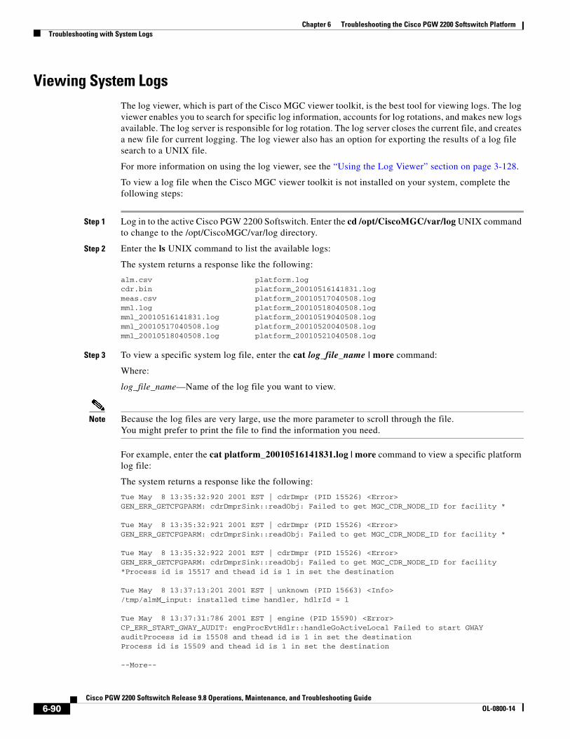
Chapter 6 Troubleshooting the Cisco PGW 2200 Softswitch PlatformTroubleshooting with System Logs
Viewing System LogsThe log viewer, which is part of the Cisco MGC viewer toolkit, is the best tool for viewing logs. The log viewer enables you to search for specific log information, accounts for log rotations, and makes new logs available. The log server is responsible for log rotation. The log server closes the current file, and creates a new file for current logging. The log viewer also has an option for exporting the results of a log file search to a UNIX file.
For more information on using the log viewer, see the “Using the Log Viewer” section on page 3-128.
To view a log file when the Cisco MGC viewer toolkit is not installed on your system, complete the following steps:
Step 1 Log in to the active Cisco PGW 2200 Softswitch. Enter the cd /opt/CiscoMGC/var/log UNIX command to change to the /opt/CiscoMGC/var/log directory.
Step 2 Enter the ls UNIX command to list the available logs:
The system returns a response like the following:
alm.csv platform.logcdr.bin platform_20010516141831.logmeas.csv platform_20010517040508.logmml.log platform_20010518040508.logmml_20010516141831.log platform_20010519040508.logmml_20010517040508.log platform_20010520040508.logmml_20010518040508.log platform_20010521040508.log
Step 3 To view a specific system log file, enter the cat log_file_name | more command:
Where:
log_file_name—Name of the log file you want to view.
Note Because the log files are very large, use the more parameter to scroll through the file.You might prefer to print the file to find the information you need.
For example, enter the cat platform_20010516141831.log | more command to view a specific platform log file:
The system returns a response like the following:
Tue May 8 13:35:32:920 2001 EST | cdrDmpr (PID 15526) <Error>GEN_ERR_GETCFGPARM: cdrDmprSink::readObj: Failed to get MGC_CDR_NODE_ID for facility *
Tue May 8 13:35:32:921 2001 EST | cdrDmpr (PID 15526) <Error>GEN_ERR_GETCFGPARM: cdrDmprSink::readObj: Failed to get MGC_CDR_NODE_ID for facility *
Tue May 8 13:35:32:922 2001 EST | cdrDmpr (PID 15526) <Error>GEN_ERR_GETCFGPARM: cdrDmprSink::readObj: Failed to get MGC_CDR_NODE_ID for facility *Process id is 15517 and thead id is 1 in set the destination
Tue May 8 13:37:13:201 2001 EST | unknown (PID 15663) <Info>/tmp/almM_input: installed time handler, hdlrId = 1
Tue May 8 13:37:31:786 2001 EST | engine (PID 15590) <Error>CP_ERR_START_GWAY_AUDIT: engProcEvtHdlr::handleGoActiveLocal Failed to start GWAY auditProcess id is 15508 and thead id is 1 in set the destinationProcess id is 15509 and thead id is 1 in set the destination
--More--
6-90Cisco PGW 2200 Softswitch Release 9.8 Operations, Maintenance, and Troubleshooting Guide
OL-0800-14

Chapter 6 Troubleshooting the Cisco PGW 2200 Softswitch PlatformTroubleshooting with System Logs
Understanding System Log MessagesEach system log message conforms to the following format:
Timestamp, Process Name, Process ID, <Log Level>, Log ID:<Message Text>
• Timestamp—Displays the date and time on the system when the log message was created, for example, “May 8 01:35:23:047 2001 EST”. The time that is displayed is presented to the millisecond level.
• Process Name—Displays the name of the process that created the log message, for example, “engine”.
• Process ID—Displays the identification number of the process that created the log message, for example, “(PID29974)”.
• Log Level—Displays the severity level of the log message, for example, “Info”.
• Log ID—Displays a short, symbolic name for the message, for example, “GEN_ERR_GETCFGPARM:”.
• Message Text—Displays the log message text, for example, “installed time handler, hdlrId = 1”. Typically, the message text requires only a single line, but the text can extend to multiple lines.
Changing the Log Level for ProcessesTo control the types of log messages that are written to the system log file, use the set-log MML command to change the logging level for system processes. The Cisco PGW 2200 Softswitch can generate many logged events, which can result in large numbers of archived system log files in the opt/CiscoMGC/var/spool directory. For example, if the maxTime parameter in the dmprSink.dat file is set to 15 minutes, the Cisco PGW 2200 Softswitch creates over 2000 files in the opt/CiscoMGC/var/spool directory daily. Therefore, you might want to limit the number of logs that are created by changing the logging level of the Cisco PGW 2200 Softswitch software processes.
Table 6-1 lists the logging levels that you can select for the Cisco PGW 2200 Softswitch software processes without severely degrading system performance.
Caution Debug level logging provides extremely verbose output and, if misused, can cause severe system performance degradation.
Table 6-1 Processes and their Lowest Possible Logging Levels
Process Lowest Logging Level Without Severe Performance Degradation
Engine Informational (the debug level causes major performance impacts—do not set).
All others Debug, but only a single process can be in debug at any time.
6-91Cisco PGW 2200 Softswitch Release 9.8 Operations, Maintenance, and Troubleshooting Guide
OL-0800-14

Chapter 6 Troubleshooting the Cisco PGW 2200 Softswitch PlatformTroubleshooting with System Logs
To change the log level of a single process, log in to the active Cisco PGW 2200 Softswitch, start an MML session, and enter the set-log:process_name:log_level,[confirm] command.
Where:
• process_name—Name of the process for which you want to change the logging level. Processes are listed in the “Understanding Processes” section on page 3-5.
• log_level—Desired logging level. The valid log levels are as follows:
– CRIT—Critical level messages
– WARN—Warning condition messages
– ERR—Error condition messages
– TRACE—Trace messages
– INFO—Informational messages
– DEBUG—Debug-level messages (lowest level). Do not set the process to this logging level unless directed to do so by the Cisco Technical Assistance Center (TAC).
• confirm—Used when changing the logging level of a process to debug (DEBUG).
Note When you set a log level, the system also generates information for all levels above the level that you select. That is, if you set a process to the INFO log level, the system also displays information for the TRACE, ERR, WARN, and CRIT levels. The order of the log levels also constitutes levels of verbosity. For instance, the CRIT level generates the least information; the DEBUG level generates the most information.
For example, to change the log level of the engine, enter the set-log:eng-01:info command.
To change the log level of all processes, log in to the active Cisco PGW 2200 Softswitch, start an MML session, and enter the set-log:all:log_level command.
Where:
log_level—Desired logging level. The valid log levels are as follows:
• CRIT—Critical level messages
• WARN—Warning condition messages
• ERR—Error condition messages
• TRACE—Trace messages
• INFO—Informational messages
Note When you set a log level, the system also generates information for all levels above the level that you select. That is, if you set a process to the INFO log level, the system also displays information for the TRACE, ERR, WARN, and CRIT levels. The order of the log levels also constitutes levels of verbosity. For instance, the CRIT level generates the least information; the DEBUG level generates the most information.
For example, to change the log level of all processes to warning, enter the set-log:all:warn command.
6-92Cisco PGW 2200 Softswitch Release 9.8 Operations, Maintenance, and Troubleshooting Guide
OL-0800-14

Chapter 6 Troubleshooting the Cisco PGW 2200 Softswitch PlatformTroubleshooting with System Logs
Note You cannot set the logging level of the process manager (PM-01) by issuing the set-log:all:log_level MML command. You can change the logging level of the process manager only by issuing the set-log:pm-01:log_level MML command.
Note You cannot enter the set-log:all:log_level MML command to set all of the processes to the debug (DEBUG) logging level.
Note The disk monitor (DSKM-01) process does not accept log-level change requests.
Creating a Diagnostics Log FileYou can create a diagnostics log file that records the MML commands and responses that you execute. To create a diagnostics log file, perform the following steps:
Step 1 Create a diagnostics log file by logging in to the active Cisco PGW 2200 Softswitch, starting an MML session, and entering the diaglog:filename:start command.
Where:
filename is the name of the diagnostics log file. Enter the name only, do not enter a suffix, such as .log.
Step 2 Perform your troubleshooting procedures.
Step 3 When you have finished troubleshooting and you want to view your diagnostics file, enter the diaglog:filename:stop command at the active Cisco PGW 2200 Softswitch.
You can find the file, which is given the name that you entered in Step 1, without a suffix, in the $BASEDIR/var/log directory. You can view the file using a text editor, such as vi.
Collecting System Data for Cisco TACCisco PGW 2200 Softswitch software has a data collection script. When you run this script, the Cisco PGW 2200 Softswitch saves a data snapshot of the system in a log file. You should run this script shortly after you discover a problem, and before taking any corrective action.
This script collects the following information in the log file:
• System name
• System boot messages
• Operating system patch level
• System patch level
• Processor information
• Disk usage
• Processor tables
6-93Cisco PGW 2200 Softswitch Release 9.8 Operations, Maintenance, and Troubleshooting Guide
OL-0800-14

Chapter 6 Troubleshooting the Cisco PGW 2200 Softswitch PlatformResolving SS7 Network Related Problems
• CPU utilization
• Number of users that are logged in
• Statistics for the Ethernet interfaces
• IP routing
• System setup
• Swap space
• Date and time of last system reboot
• Permissions for the configuration library (CONFIG_LIB)
• File permissions for the /opt/CiscoMGC/etc and /opt/CiscoMGC/bin directories
• Copy of the XECfgParm.dat file
To collect your system data snapshot, perform the following steps:
Step 1 Log in to the active Cisco PGW 2200 Softswitch, and enter the cd /opt/CiscoMGC/local UNIX command to change directories.
Step 2 Enter the collectdata command to run the system data snapshot script:
The system returns a response that indicates the name of the file and the data path to the file.
Note The name of the log file contains the time stamp when the file was created and the name of the Cisco PGW 2200 Softswitch. The file is always saved to the opt/CiscoMGC/var/log directory.
Step 3 Provide the log file to the Cisco TAC as instructed by TAC personnel.
Resolving SS7 Network Related ProblemsThe Cisco PGW 2200 Softswitch platform is a standard Service Switching Point (SSP) in an SS7 network. The SS7 network carries two types of signals:
• Circuit-related
• Noncircuit-related
The signals that are involved in the setup and teardown of bearer circuits are circuit-related. The Cisco PGW 2200 Softswitch uses non-circuit-related signals for all the ancillary services that the SS7 network provides, including database access and network management.
The SS7 protocol is composed of several levels or parts, including the following:
• Message Transfer Part (MTP)—Levels 1 (MTP1) through 3 (MTP3)
• Signaling Connection Control (SCCP)
• Application Service Part (ASP)
• Transaction Capabilities Application Part (TCAP)
• Telephony User Part (TUP)
• ISDN User Part (ISUP)
6-94Cisco PGW 2200 Softswitch Release 9.8 Operations, Maintenance, and Troubleshooting Guide
OL-0800-14

Chapter 6 Troubleshooting the Cisco PGW 2200 Softswitch PlatformResolving SS7 Network Related Problems
• Broadband ISUP (BISUP)
There are many variations of the different parts of the SS7 protocol stack. MTP has ANSI, ITU, Bellcore, and several national variations. Each country and each major carrier might have slightly different variations of a part to fit its particular needs.
The SS7 network must have the highest degree of reliability. Each switch with access to the SS7 network must be configured to a preconceived set of network parameters. There is some risk that the person configuring a switch is not using the correct set of parameters or values. Misconfiguration is the root cause of most SS7 problems at both the MTP layers and upper layers of the SS7 protocol. A single parameter value, such as an incorrect timer value, can cause SS7 connectivity to operate improperly or fail completely.
The first, and most important, step in troubleshooting SS7 related problems is to understand, and fully document, the SS7 network topology and protocols. The protocol documents are used as a reference over the months and years of maintenance on the SS7 network.
The following sections describe troubleshooting SS7 network:
• Signaling Channel Problems, page 6-95
• Signaling Destination Problems, page 6-100
• Signaling Channel Troubleshooting Procedures, page 6-103
Signaling Channel ProblemsThe Cisco PGW 2200 Softswitch software generates signaling alarms if it detects problems with the transportation of data on a signaling channel or at a signaling destination.
Signaling alarms have four classifications of severity:
• Critical
• Major
• Minor
• Informational
Note Multiple alarms are likely to occur for severe failures. For example, SUPPORT FAIL and SC FAIL would typically occur with LIF LOS.
Signaling links are the dedicated communication channels that the Cisco PGW 2200 Softswitch uses to transfer signaling information between itself, the Cisco ITP-Ls, and the Signal Transfer Points (STPs). Signaling links provide the necessary delivery reliability for higher-layer SS7 signaling protocols.
You can use the Cisco PGW 2200 Softswitch software and MML commands to manage signaling channels and lines. You can retrieve signaling channel attributes, change the states of signaling channels, and change the state of signaling lines. See Chapter 3, “Cisco PGW 2200 Softswitch Platform Operations,” for detailed information.
Note For more information on MML commands, see Cisco PGW 2200 Softswitch Release 9 MML Reference.
Because all types of signaling channels have basically the same functionality, you manage them similarly. Unless otherwise noted, all commands, counters, and alarms that are documented in this section apply to all types of signaling channels.
6-95Cisco PGW 2200 Softswitch Release 9.8 Operations, Maintenance, and Troubleshooting Guide
OL-0800-14

Chapter 6 Troubleshooting the Cisco PGW 2200 Softswitch PlatformResolving SS7 Network Related Problems
The following sections describe signaling channel problems:
• SS7 Link is Out-of-Service, page 6-96
• SS7 Load Sharing Malfunction, page 6-97
• Physical Layer Failures, page 6-98
• Configuration Errors, page 6-98
• Supporting Entity Failures, page 6-99
• Incomplete Signaling, page 6-99
• Changing Service States, page 6-99
SS7 Link is Out-of-Service
If an SS7 link is out-of-service on your system, perform the following steps:
Step 1 If you have not already collected system data, refer to the method that is described in the “Collecting System Data for Cisco TAC” section on page 6-93.
Step 2 Change the service state of the SS7 link to in-service, as described in the “Setting the Service State of a C7/SS7 Link or Linkset” section on page 6-105.
If the SS7 link returns to service, the procedure is complete. Otherwise, proceed to Step 3.
Step 3 Verify that MTP1 is working correctly on the affected Cisco ITP-L, as described in the “Identifying MTP1 Communication Problems” section on page B-12.
If MTP1 is working correctly on the affected Cisco ITP-L, proceed to Step 4. Otherwise, correct the MTP1 problems according to instructions in the “Resolving MTP1 Communication Problems” section on page B-12.
Repeat Step 2. If the link returns to service, the procedure is complete. Otherwise, proceed to Step 7.
Step 4 Search for excessive SUREM/AERM errors and link failure messages in the active system log file, as described in the “Viewing System Logs” section on page 6-90.
If MTP2 is working correctly on the Cisco PGW 2200 Softswitch, proceed to Step 5. Otherwise, correct the MTP2 problems according to instructions in the “Resolving MTP2 Communication Problems” section on page B-13.
Repeat Step 1. If the link returns to service, the procedure is complete. Otherwise, proceed to Step 5.
Step 5 Verify that MTP2 is working correctly on the affected Cisco ITP-L, as described in the “Identifying MTP2 Communication Problems” section on page B-13.
If MTP2 is working correctly on the affected Cisco ITP-L, proceed to Step 6. Otherwise, correct the MTP2 problems according to instructions in the “Resolving MTP2 Communication Problems” section on page B-13.
Repeat Step 1. If the link returns to service, the procedure is complete. Otherwise, proceed to Step 6.
Step 6 Troubleshoot the SS7 link by following the instructions in the “Troubleshooting SS7 Link Problems” section on page B-5.
If you do not find any problems, proceed to Step 7. Otherwise, repeat Step 2. If the link returns to service, the procedure is complete. Otherwise, proceed to Step 7.
6-96Cisco PGW 2200 Softswitch Release 9.8 Operations, Maintenance, and Troubleshooting Guide
OL-0800-14

Chapter 6 Troubleshooting the Cisco PGW 2200 Softswitch PlatformResolving SS7 Network Related Problems
Step 7 Contact the Cisco TAC to analyze the problem further and to determine a solution. For more information about contacting the Cisco TAC, see the “Obtaining Documentation and Submitting a Service Request” section on page xviii.
SS7 Load Sharing Malfunction
If load sharing on your SS7 links or routes is not working properly, perform the following steps:
Step 1 If you have not already collected system data, refer to the method that is described in the “Collecting System Data for Cisco TAC” section on page 6-93.
Step 2 Log in to the active Cisco PGW 2200 Softswitch, start an MML session, and enter the prov-rtrv:c7iplnk:“all” command to verify the priority settings of the SS7 links.
The system returns a response like the following:
MGC-02 - Media Gateway Controller 2001-07-24 12:11:44M RTRV "session=active:c7iplnk" /*NAME LNKSET PRI SLC TIMESLOT SESSIONSET---- ------ --- --- -------- -----------ls1link1 ls1 1 0 0 c7-slt1ls1link2 ls1 1 1 0 c7-slt2
The PRI field in the response shows the priority settings for your SS7 links. For load sharing to work properly, the priority settings for all of the links should be set to 1.
Step 3 Enter the prov-rtrv:ss7route:“all” command to verify the priority settings of the SS7 routes.
The system returns a response like the following:
MGC-02 - Media Gateway Controller 2001-07-24 12:25:05M RTRV "session=active:ss7route" /*NAME OPC DPC LNKSET PRI---- --- --- ------ ---route1 opc1 dpc1 ls1 1rout2 opc1 dpc2 ls2 1rt3 opc2 scp2 ls-itu 1rt1 opc2 stp1 ls-itu 1rt2 opc2 scp1 ls-itu 1 */
The PRI field in the response shows the priority settings for the SS7 routes. For load sharing to work properly, the priority settings for all of the routes should be set to 1.
Step 4 Start a provisioning session, as described in “Starting a Provisioning Session” section on page 3-64.
Step 5 If any of the SS7 links show a priority other than 1, change the priority settings to ensure proper link load sharing. Before changing the priority settings for the link, take the link out-of-service, as described in the “Setting the Service State of a C7/SS7 Link or Linkset” section on page 6-105.
6-97Cisco PGW 2200 Softswitch Release 9.8 Operations, Maintenance, and Troubleshooting Guide
OL-0800-14

Chapter 6 Troubleshooting the Cisco PGW 2200 Softswitch PlatformResolving SS7 Network Related Problems
Step 6 Modify the priority settings of the link by entering the prov-ed:c7iplnk:name=“lnkname”,pri=1 command.
Where:
lnkname—Name of an SS7 link that is not set to priority 1.
Repeat this step for each link that is not set to priority 1.
Step 7 If any of the SS7 routes show a priority other than 1, change the priority settings to ensure proper route load sharing. Before changing the priority settings for the route, take the route out-of-service, as described in the “Setting the Service State of an SS7 Signaling Service” section on page 6-104.
Step 8 Modify the priority settings of the link by entering the prov-ed:ss7route:name=“rtname”,pri=1 command.
Where:
rtname—Name of an SS7 route that is not set to priority 1.
Repeat this step for each route that is not set to priority 1.
Step 9 Save and activate your provisioning changes, as described in the “Saving and Activating your Provisioning Changes” section on page 3-65.
If the condition clears, the procedure is complete. Otherwise, proceed to Step 10.
Step 10 Contact the Cisco TAC to analyze the problem further and to determine a solution. For more information about contacting the Cisco TAC, see the “Obtaining Documentation and Submitting a Service Request” section on page xviii.
Physical Layer Failures
The major issues pertaining to the physical layer of an SS7 signaling link are related to cabling, clock source, and connector pinouts. The cable should be of high quality (shielded) and the connectors should be attached and crimped solidly. Because SS7 links are synchronous, one side of the link must provide the clock source and the other side must use this clock signal to read the bits.
The most common mistake is to use the wrong cable pinouts for a specific physical configuration. Make sure that the connector has the correct number of pins (RJ-45, DB-25) and that each pin maps to the correct signal. Several physical layers are supported, including ANSI T1, CEPT E1, and V.35. Ensure that the cable complies with the connector and the physical protocol being used.
If the configuration appears to be valid and the cable pinout is good, check that the signal is being sent and received correctly. Use a Bit Error Rate Tester (BERT) or perform a signal loopback on the interface. It is possible that the cable is bad, so try to replace it. The line card might be defective, so consider replacing it.
Configuration Errors
The most common mistake in SS7 signal link configuration is to misconfigure the Signal Link Code (SLC) for the SS7 link. The SLC is a preconfigured code on both ends of the link. If the SLC or the point codes do not match, the link does not align and no transmission can take place.
For T1 and E1 connectors, an SS7 signaling link is carried in a single 56- or 64-kbps time slot. The time slot that is used must also match on both sides of the link.
6-98Cisco PGW 2200 Softswitch Release 9.8 Operations, Maintenance, and Troubleshooting Guide
OL-0800-14

Chapter 6 Troubleshooting the Cisco PGW 2200 Softswitch PlatformResolving SS7 Network Related Problems
Ensure that the MTP2 timers and thresholds match the network defaults. Confirm that the far-end switch or STP has the same values as your system.
When you use a Cisco ITP-L to terminate MTP2, confirm that the RUDP parameters match on both sides and are consistent with the documentation.
Supporting Entity Failures
An SS7 signaling link has a hierarchy of network element entities that must be functioning before the link can function. The entities include the physical interface (discussed previously) and the control software for the link. If any of these entities fail, the link also fails.
Incomplete Signaling
The following problems can cause a link to fail between the Cisco ITP-L and the Cisco PGW 2200 Softswitch.
• Ethernet card failure on the Cisco ITP-L
• Ethernet card failure on the Cisco switch
• Cisco switch failure
• Fast Ethernet interface card failure on the Cisco PGW 2200 Softswitch
In each of the preceding cases, it is impossible to transfer MTP3 signaling messages from the Cisco ITP-L to the Cisco PGW 2200 Softswitch. Cisco ITP-L platform failure (which is equivalent to MTP2 failure) prevents signaling messages from going to MTP3. The MTP2 layer on the Cisco ITP-L is supposed to send SIPO messages to the STP mated pair to start the changeover procedure. The mated STP pair, which detects timer expiration and link unavailability, detects Cisco ITP-L platform failure on the SS7 network.
Changing Service States
Signal channels comply with the Generic Service State model that is defined in the “Physical Layer Failures” section on page 6-98. You can change the service state of a signaling channel by using the following transition requests. Note that there is a difference between a desired service state and an actual service state, and the Cisco PGW 2200 Softswitch might not be able to honor the request. For example, a signal channel that is out-of-service because of an equipment failure cannot transition to an in-service state upon request. The Cisco PGW 2200 Softswitch attempts to bring the channel in-service, but it fails. You must resolve the failure before the transition can succeed.
• In-service (IS)—Signaling channel is requested to start providing service.
• Out-of-service (OOS)—Signaling channel is requested to stop providing service.
For some protocols, the system accepts this request, but does not grant the request until after all calls have been released. During the interim period, the channel service state appears as OOS, PEND.
• Forced out-of-service (FOOS)—Signaling channel is requested to stop providing service immediately, regardless of related call states, and to drop currently active calls.
• Inhibit (INH)—Signaling channel is requested to transition to an inhibit state. This state is for SS7 signaling channels only and fails on other types of signaling channels.
In this state, the channel is active but does not provide service for call processing. If the signaling channel is the last one in the signal path, the system denies the inhibit request and returns an error.
6-99Cisco PGW 2200 Softswitch Release 9.8 Operations, Maintenance, and Troubleshooting Guide
OL-0800-14

Chapter 6 Troubleshooting the Cisco PGW 2200 Softswitch PlatformResolving SS7 Network Related Problems
• Uninhibit (UNH)—Signaling channel is requested to be removed from an INH state and to provide service for call processing. This state is for SS7 signaling channels only and fails on other types of signaling channels.
Use this option (UNH), rather than the IS option, to return an inhibited signaling channel to service.
Note Changing the state of a signaling channel generates an alarm. For more information on retrieving and clearing alarms, see the “Troubleshooting Using Cisco PGW 2200 Softswitch Alarms” section on page 6-3.
Signaling Destination ProblemsSignaling destinations refer to the endpoints of a network. Typically, if signaling links are in service, the signaling destinations should also be in service.
For ISDN signaling, the signaling channel is in service if the Cisco PGW 2200 Softswitch can communicate with the media gateway and ISDN backhaul is configured. The destination is in service if the signaling channel is in service and the remote ISDN device is in service.
Apparent mismatches can occur because of:
• SS7 traffic restart processing (TRW/TRA)
• SS7 STP problems
• Configuration problems
• Software problems
The Cisco PGW 2200 Softswitch regards an SS7 STP as an adjacent point code (APC). SS7 MTP uses a message exchange called Signaling Link Test Message (SLTM)/Signaling Link Test Acknowledgment (SLTA) to confirm that the far-end point code is the one configured. The SLTM consists of the originating point code (OPC) of the Cisco PGW 2200 Softswitch, an APC number, and an SS7 network indicator. If the values for these parameters match with the values used at the far-end switch, an SLTA is returned. If the value for any of these parameters does not match, the far-end switch does not send an SLTA. The Cisco PGW 2200 Softswitch drops the link and tries to realign it. This process continues until the SLTM parameters match on both sides. The symptom of this problem is SS7 links dropping and recovering in roughly 30-second cycles (this symptom is referred to as bouncing).
The following sections describe signaling destination problems:
• Bouncing SS7 Links, page 6-101
• Configuration Errors, page 6-101
• Traffic Restart, page 6-102
• SS7 Destination is Out of Service, page 6-102
• SS7 Route is Out of Service, page 6-102
• SS7 Destination is Unavailable, page 6-103
6-100Cisco PGW 2200 Softswitch Release 9.8 Operations, Maintenance, and Troubleshooting Guide
OL-0800-14

Chapter 6 Troubleshooting the Cisco PGW 2200 Softswitch PlatformResolving SS7 Network Related Problems
Bouncing SS7 Links
Usually, mismatched signaling link codes (SLCs) or DPCs/OPCs between the Cisco PGW 2200 Softswitch and the far end cause this condition. To resolve a bouncing SS7 condition, perform the following steps:
Step 1 If you have not already collected system data, refer to the method that is described in the “Collecting System Data for Cisco TAC” section on page 6-93.
Step 2 Verify that the SLC, OPC, and DPC provisioning settings match with the settings used on the far end. To verify settings, enter the prov-rtrv MML command for the SS7 link, OPC, and DPC components, as described in the “Retrieving Provisioning Data” section on page 3-69. Compare the values that are retrieved with the settings used by the far end.
If the provisioning settings for the SLC, OPC, and DPC match the settings that are used on the far end, proceed to Step 3. Otherwise, modify the settings to match the settings that are used on the far end. See the “Invoking Dynamic Reconfiguration” section on page 3-66 for more information about modifying the settings of a provisioned component. If that clears the problem, the procedure is complete. Otherwise, proceed to Step 3.
Step 3 Ensure that the local MTP3 timer settings match the network defaults by following the instructions in the “Verifying MTP3 Timers” section on page 6-108.
If the local MTP3 timer settings match the network defaults, proceed to Step 4. Otherwise, contact the far-end to determine whether they can change timer settings to match your settings. If that clears the problem, the procedure is complete. Otherwise, proceed to Step 4.
Step 4 View the system logs, as described in the “Viewing System Logs” section on page 6-90, looking for excessive alignment error monitoring (AERM) logs. If large numbers of AERM logs are present, proceed to Step 5.
If no AERM logs are present, proceed to Step 6.
Step 5 Determine why the link is not aligning properly by checking the alignment status on the Cisco ITP-L associated with the affected link, as described in the “Verifying the Link Alignment Status” section on page B-6.
If the condition clears, the procedure is complete. Otherwise, proceed to Step 6.
Step 6 Contact the Cisco TAC to analyze the problem further and to determine a solution. For more information about contacting the Cisco TAC, see the “Obtaining Documentation and Submitting a Service Request” section on page xviii.
Configuration Errors
If the SS7 DPC is fully associated, it can have the same SLTM/SLTA problems that were described in the preceding section.
If the SS7 DPC is quasi-associated, the most common cause for failure is a route misconfiguration. Review the route information between the Cisco PGW 2200 Softswitch and the DPC to ensure that the APCs are valid, the route priorities are set correctly, and the route uses the appropriate linkset.
6-101Cisco PGW 2200 Softswitch Release 9.8 Operations, Maintenance, and Troubleshooting Guide
OL-0800-14

Chapter 6 Troubleshooting the Cisco PGW 2200 Softswitch PlatformResolving SS7 Network Related Problems
Traffic Restart
Ensure that the MTP3 traffic restart timers and thresholds agree with the network defaults. Confirm that the far-end switch or STP has the same values.
SS7 Destination is Out of Service
Typically, a signaling destination is out of service when all the SS7 links from the Cisco PGW 2200 Softswitch to the destination or APC are out of service, or when all of the SS7 links from the destination to the APC are out of service.
To restore an SS7 destination to service, perform the following steps:
Step 1 If you have not already collected system data, refer to the method that is described in the “Collecting System Data for Cisco TAC” section on page 6-93.
Step 2 Contact your SS7 provider to verify the links from the DPC to the associated STP.
Step 3 Verify the state of the signaling channels, as described in the “Verifying the Status of all Signaling Services” section on page 3-9.
If any of the SS7 links are out-of-service, restore the links according to the instructions in the “SS7 Link is Out-of-Service” section on page 6-96. If all of the SS7 links to a destination are out-of-service, restore the destination as described in the “SS7 Destination is Out of Service” section on page 6-102.
If the condition clears, the procedure is complete. Otherwise, proceed to Step 4.
Step 4 Contact the Cisco TAC to analyze the problem further and to determine a solution. For more information about contacting the Cisco TAC, see the “Obtaining Documentation and Submitting a Service Request” section on page xviii.
SS7 Route is Out of Service
To restore an SS7 route to service, perform the following steps:
Step 1 If you have not already collected system data, refer to the method that is described in the “Collecting System Data for Cisco TAC” section on page 6-93.
Step 2 Change the service state of the destination to in-service, as described in the “Setting the Service State of a Signaling Service” section on page 6-103.
If the destination goes into service, the procedure is complete. Otherwise, proceed to Step 3.
Step 3 Verify the state of the signaling channels, as described in the “Verifying the Status of all Signaling Services” section on page 3-9.
If none of the SS7 links are in-service, proceed to Step 4. If all or at least one of the SS7 links to the destination are in-service, then contact your SS7 provider to verify the links from the DPC to the associated STP.
Step 4 Determine why the link is not aligning properly by checking the alignment status on the Cisco ITP-L that is associated with the affected link, as described in the “Verifying the Link Alignment Status” section on page B-6.
If the condition clears, the procedure is complete. Otherwise, proceed to Step 5.
6-102Cisco PGW 2200 Softswitch Release 9.8 Operations, Maintenance, and Troubleshooting Guide
OL-0800-14

Chapter 6 Troubleshooting the Cisco PGW 2200 Softswitch PlatformResolving SS7 Network Related Problems
Step 5 Contact the Cisco TAC to analyze the problem further and to determine a solution. For more information about contacting the Cisco TAC, see the “Obtaining Documentation and Submitting a Service Request” section on page xviii.
SS7 Destination is Unavailable
An SS7 destination is unavailable when all of the routes to the destination are out-of-service. Perform the procedure that is defined in the “SS7 Route is Out of Service” section on page 6-102.
Signaling Channel Troubleshooting ProceduresThe following sections present procedures that you can follow to resolve problems that are associated with the Cisco PGW 2200 Softswitch platform signaling connections to other networks:
• Setting the Service State of a Signaling Service, page 6-103
• Setting the Service State of an SS7 Signaling Service, page 6-104
• Setting the Service State of a C7/SS7 Link or Linkset, page 6-105
• Setting the Service State of an IP Link, page 6-105
• Setting the Service State of an IP Route, page 6-106
• Setting the Service State of a D-channel, page 6-106
• Setting the Service State of a Local Subsystem Number, page 6-107
• Setting the Service State of an Association, page 6-107
• Verifying MTP Timer Settings, page 6-107
• Modifying Configurable Timers, page 6-109
• Managing Japanese SS7 Signaling Link Tests, page 6-118
• Managing Japanese SS7 Signaling Route Tests, page 6-119
• Verifying Proper Loading of a Dial Plan, page 6-121
• Verifying Configuration to Support Multiple Versions of SS7, page 6-121
• Resolving an Association Alarm, page 6-122
• Converting Stored and Sent Point Code Values, page 6-122
Setting the Service State of a Signaling Service
To set the service state of a signaling service, perform the following steps:
Caution Use the set-dest command only while you are dynamically reconfiguring the system. Do not use the set-dest command to take a signaling service out-of-service during a maintenance session, because all calls associated with the specified signaling service are dropped. Instead, when you need to perform maintenance, use the blk-cic command to block the CICs associated with the signaling service.
6-103Cisco PGW 2200 Softswitch Release 9.8 Operations, Maintenance, and Troubleshooting Guide
OL-0800-14

Chapter 6 Troubleshooting the Cisco PGW 2200 Softswitch PlatformResolving SS7 Network Related Problems
Step 1 Log in to the active Cisco PGW 2200 Softswitch, start an MML session, and enter the set-dest:sig_srv:serv_state command.
Where:
• sig_srv—MML name of the desired signaling service.
• serv_state—Desired service state. The following service states are valid:
– IS—Places a signaling service in service.
– OOS—Takes a signaling service out of service.
Note Before you can take a NAS signaling service out of service, you must shut down the D-channel on the associated media gateway. See the documentation for the media gateway for more information on shutting down D-channels.
For example, to set the service state of a signaling service called sigsrv1 to IS, enter the set-dest:sigsrv1:IS command:
Step 2 Verify that the state of the destination has changed by entering the rtrv-dest command, as described in the Retrieving Signaling Service States, page 3-45.
Setting the Service State of an SS7 Signaling Service
To set the service state of an SS7 signaling service, perform the following steps:
Caution Use the set-spc command only while you are dynamically reconfiguring the system. Do not use the set-spc command to take an SS7 signaling service out-of-service during a maintenance session, because all calls associated with the specified SS7 signaling service are dropped. Instead, when you need to perform maintenance, use the blk-cic command to block the CICs associated with the SS7 signaling service.
Step 1 Log in to the active Cisco PGW 2200 Softswitch, start an MML session, and enter the set-spc:ss7_srv:serv_state command.
Where:
• ss7_srv—MML name of the SS7 signaling service that you want to set.
• serv_state—Service state you want to set. The following service states are valid:
– IS—Places the SS7 signaling service in service.
– OOS—Takes the SS7 signaling service out of service.
For example, to set the service state of an SS7 signaling service called ss7srv1 to IS, enter the set-spc:ss7srv11:IS command:
Step 2 Verify that the state of the SS7 signaling service has changed by entering the rtrv-spc CRIT command, as described in the Retrieving the State of SS7 Signaling Services, page 3-48.
6-104Cisco PGW 2200 Softswitch Release 9.8 Operations, Maintenance, and Troubleshooting Guide
OL-0800-14

Chapter 6 Troubleshooting the Cisco PGW 2200 Softswitch PlatformResolving SS7 Network Related Problems
Setting the Service State of a C7/SS7 Link or Linkset
To change the service state of an SS7 link, log in to the active Cisco PGW 2200 Softswitch, start an MML session, and enter the set-c7lnk:c7link_name:serv_state command.
Where:
• c7link_name—MML name of the SS7 link you want to modify.
• serv_state—Service state to set. Valid values for SS7 links are IS, OOS, FOOS, INH, and UNH.
Note To set the last link in a linkset out of service, you must enter the FOOS service state in the command.
For example, to set the service state of the SS7 link (c7link1) to IS, enter the set-c7lnk:c7link1:IS command.
Verify if the selected SS7 link is in the proper service state by performing the procedure in the Retrieving Service State of C7/SS7 Links or Linksets, page 3-45.
Note To modify the service state of the backhaul link for the Cisco ITP-L, set the state of all link types that are associated with that Cisco ITP-L. The possible link types are S77 links (c7lnk), D-channels, (dchan), and IP links (iplnk).
Setting the Service State of an IP Link
To change the service state of an IP link, login to the active Cisco PGW 2200 Softswitch, start an MML session, and enter the set-iplnk:iplink_name:serv_state[::confirm] command.
Where:
• iplink_name—MML name of the IP link you want to modify.
• serv_state—Service state that you want to set. Valid values for IP links are IS, OOS, and FOOS.
• confirm—This parameter is required when you are setting the service state of an MGCP link. Other types of IP links do not require this parameter.
For example, to set the service state of the IP link (iplink1) to IS, enter the set-iplnk:iplink1:IS command.
For example, enter the set-iplnk:mgcplnk1:IS:confirm command to set the service state of an MGCP link called mgcplnk1 to IS.
Verify that the selected IP link is in the proper service state by performing the procedure in the “Retrieving the Service State for IP Links” section on page 3-46.
Note To modify the service state of the backhaul link for the Cisco ITP-L, set the state of all link types that are associated with that Cisco ITP-L. The possible link types are S77 links (c7lnk), D-channels (dchan), and IP links (iplnk).
6-105Cisco PGW 2200 Softswitch Release 9.8 Operations, Maintenance, and Troubleshooting Guide
OL-0800-14

Chapter 6 Troubleshooting the Cisco PGW 2200 Softswitch PlatformResolving SS7 Network Related Problems
Setting the Service State of an IP Route
To change the service state of an IP route, log in to the active Cisco PGW 2200 Softswitch, start an MML session, and enter the set-iproute:iproute_name:serv_state[,confirm] command.
Where:
• iproute_name—MML name of the IP route you want to modify.
• serv_state—Service state that you want to set. Valid values for IP links are IS, OOS, and FOOS.
• confirm—Required parameter when you are setting the service state to OOS or FOOS.
Note You cannot use this command on the standby Cisco PGW 2200 Softswitch.
You can set an IP route in any of the following combinations of primary and secondary service states to OOS or FOOS:
• IS
• OOS, CONF
• OOS, OFF_DUTY
• OOS, STDBY
To set an IP route to IS, the IP route must have a primary service state of OOS and secondary service state of COOS.
For example, to set the service state of an IP route called iprte1 to OOS, enter the set-iproute:iprte1:OOS,confirm command.
Note Verify that the selected IP route is in the proper service state by performing the procedure in the “Retrieving the Service State for IP Routes” section on page 3-46.
Setting the Service State of a D-channel
To change the service state of a D-channel, login to the active Cisco PGW 2200 Softswitch, start an MML session, and enter the set-dchan:dchan_name:serv_state command.
Where:
• dchan_name—MML name of the D-channel you want to modify.
• serv_state—Service state to set. Valid values for D-channels are IS and OOS.
For example, to set the service state of the D-channel, dchan-1, to IS, enter the set-dchan:dchan-1:IS command.
Verify that the selected D-channel is in the proper service state by performing the procedure in the “Retrieving the Service State of D-Channels” section on page 3-47.
Note To modify the service state of the backhaul link for the Cisco ITP-L, set the state of all link types that are associated with that Cisco ITP-L. The possible link types are S77 links (c7lnk), D-channels (dchan), and IP links (iplnk).
6-106Cisco PGW 2200 Softswitch Release 9.8 Operations, Maintenance, and Troubleshooting Guide
OL-0800-14

Chapter 6 Troubleshooting the Cisco PGW 2200 Softswitch PlatformResolving SS7 Network Related Problems
Setting the Service State of a Local Subsystem Number
To set the service state of a local subsystem number (LSSN), perform the following steps:
Step 1 Log in to the active Cisco PGW 2200 Softswitch, start an MML session, and enter the set-lssn-state:ssn:serve_state command.
Where:
• ssn—MML name of the desired LSSN.
• serv_state—Desired service state. The following service states are valid:
– IS—Places an LSSN in service.
– OOS—Takes an LSSN out of service.
For example, to set the service state of an LSSN called lnp to IS, enter the set-lssn-state:lnp:IS command.
Step 2 Verify that the state of the LSSN has changed by entering the rtrv-lssn command, as described in the “Retrieving the State of All Local Subsystem Numbers” section on page 3-49.
Setting the Service State of an Association
To change the service state of an association, log in to the active Cisco PGW 2200 Softswitch, start an MML session, and enter the set-association:assoc_name:serv_state[,confirm] command.
Where:
• assoc_name—MML name of the association you want to modify.
• serv_state—Service state to set. Valid values for IP links are IS, OOS, and FOOS.
• confirm—Required parameter when you are setting the service state to OOS or FOOS.
Note You cannot use this command on the standby Cisco PGW 2200 Softswitch.
For example, to set the service state of the association, assoc1, to OOS, enter the set-association:assoc1:OOS,confirm command.
Verify that the selected association is in the proper service state by performing the procedure in the “Retrieving the Service State for Associations” section on page 3-50.
Verifying MTP Timer Settings
When resolving signaling problems between the Cisco PGW 2200 Softswitch and an associated SS7 network element (such as an STP), you might need to verify that the MTP2 and MTP3 timer settings that the Cisco PGW 2200 Softswitch uses conform to settings of the associated SS7 network element. Use MML commands on the Cisco PGW 2200 Softswitch to retrieve the settings for the MTP2 and MTP3 timers. The following subsections describe methods for verifying the MTP timer settings on the Cisco PGW 2200 Softswitch.
6-107Cisco PGW 2200 Softswitch Release 9.8 Operations, Maintenance, and Troubleshooting Guide
OL-0800-14

Chapter 6 Troubleshooting the Cisco PGW 2200 Softswitch PlatformResolving SS7 Network Related Problems
Note See Cisco PGW 2200 Softswitch Release 9.8 Provisioning Guide for more information on the MTP timers.
Verifying MTP2 Timers
To verify the values that are used for the MTP2 timers on the Cisco ITP-Ls, complete the following steps:
Step 1 Enter the #show ss7 mtp2 timer channel command at the Cisco ITP-L to display the settings for the MTP2 timers.
Where:
channel—Specifies a channel, 0 through 3.
The system returns a message like the following:
SS7 MTP2 Timers for channel 0 in millisecondsProtocol version for channel 0 is Japan NTT Q.703 Version 1-1 T1 aligned/ready = 15000 T2 not aligned = 5000 T3 aligned = 3000 T4 Emergency Proving = 3000 T4 Normal Proving = 3000 T5 sending SIB = 200 T6 remote cong = 3000 T7 excess ack delay = 2000 T8 errored int mon = 0 TA SIE timer = 20 TF FISU timer = 20 TO SIO timer = 20 TS SIOS timer = 20
Step 2 Compare the MTP2 timers settings that are listed for the Cisco ITP-Ls to the MTP2 timers that are used at the associated destination.
If the MTP2 timers settings match, the timer settings are not causing the signaling problem. Continue troubleshooting the problem.
If the MTP2 timers settings do not match, perform the procedure in the “Modifying MTP2 Timers” section on page 6-109.
Verifying MTP3 Timers
To verify the values that are used for the MTP3 timers, complete the following steps:
Step 1 Log on to active Cisco PGW 2200 Softswitch, start an MML session, and enter the prov-rtrv:lnksetprop:name=“MML_name” command to display the settings for the MTP3 timers.
Where:
MML_name—MML name for the linkset that is associated with the MTP3 timers you want to verify.
6-108Cisco PGW 2200 Softswitch Release 9.8 Operations, Maintenance, and Troubleshooting Guide
OL-0800-14

Chapter 6 Troubleshooting the Cisco PGW 2200 Softswitch PlatformResolving SS7 Network Related Problems
The system returns a message like the following:
MGC-01 - Media Gateway Controller 2000-07-27 18:33:56M RTRV"session=nsite04:sigsvcprop"/*
mtp3ApcMtpRstrtT28 = 50mtp3DlnkConnAckT7 = 10mtp3FrcUnhT13 = 10mtp3InhAckT14 = 20mtp3LocInhTstT20 = 900mtp3MaxSltTries = 2mtp3MsgPriority = 2mtp3MtpRstrtT24 = 60mtp3RepeatRstrtT26 = 150mtp3TfrUsed = falsemtp3TraSnT29 = 600mtp3tstSltmT1 = 60mtp3tstSltmT2 = 600mtp3UnhAckTl2 = 10reference = ANSI96
Step 2 Compare the listed MTP3 timers settings to the MTP3 timers that are used at the associated destination.
If the MTP3 timers settings match, the timer settings are not causing the signaling problem. Continue troubleshooting the problem.
Modifying Configurable Timers
In earlier releases of the Cisco PGW 2200 Softswitch software, you could not modify the settings of the message transfer part level 3 (MTP3) and redundant link manager (RLM) timers. You can modify the settings of these timers. The following sections describe the procedures for verifying and modifying the timers:
• Modifying MTP2 Timers, page 6-109
• Verifying and Modifying MTP3 Timer Settings, page 6-110
• Verifying and Modifying RLM Timers, page 6-112
• Verifying and Modifying ISUP Timer Settings, page 6-113
• Rebooting Your System to Modify Properties, page 6-117
Modifying MTP2 Timers
Use the following MML commands at the Cisco ITP-L to modify the settings for the MTP2 timers:
Router (config)#ss7 mtp-variant standard channelRouter(config-standard)# parameters
Where:
• standard—Name of the SS7 standard that is used for your links. Valid values are Bellcore, ITU, NTT, and TTC
• channel—Specifies a channel, 0 through 3
• parameters—Timer number and the new value for the timer
6-109Cisco PGW 2200 Softswitch Release 9.8 Operations, Maintenance, and Troubleshooting Guide
OL-0800-14

Chapter 6 Troubleshooting the Cisco PGW 2200 Softswitch PlatformResolving SS7 Network Related Problems
Note See Cisco Signaling Link Terminal for more information on the parameters for this command.
In the following example, the aligned/ready timer duration on channel 0 is set to 30,000 ms:
Router(config)# ss7 mtp2-variant Bellcore 0Router(config-Bellcore)# T1 30000
In the following example, the aligned/ready timer is restored to its default value of 13,000 ms:
Router(config)# ss7 mtp2-variant Bellcore 0Router(config-Bellcore)# no T1
After the modification is complete, verify the new settings according to the procedure in the “Verifying MTP2 Timers” section on page 6-108.
Verifying and Modifying MTP3 Timer Settings
When resolving signaling problems between the Cisco PGW 2200 Softswitch and an associated SS7 network element (such as an STP), you might need to verify that the Cisco PGW 2200 Softswitch MTP3 timer settings conform to settings on the associated SS7 network element. If the settings do not match, you must modify the settings for the MTP3 timers.
Note See Cisco PGW 2200 Softswitch Release 9.8 Provisioning Guide for more information on the MTP timers.
To verify and modify the values that are used for the MTP3 timers, complete the following steps:
Step 1 Log on to active Cisco PGW 2200 Softswitch, start an MML session, and enter the prov-rtrv:sigsvcprop:name=“protocol” command to display the settings for the MTP3 timers.
Where:
protocol is the MML name for the SS7 protocol family being used, such as SS7-ANSI or SS7-ITU.
The system returns a message like the following:
MGC-01 - Media Gateway Controller 2001-06-01 10:31:00M RTRV "session=active:lnksetprop" /*mtp2AermEmgThr = 1mtp2AermNrmThr = 4mtp2CongDiscard = falsemtp2LssuLen = 1mtp2MaxAlignRetries = 5mtp2MaxMsuFrmLen = 272mtp2MaxOutsFrames = 127mtp2ProvingEmgT4 = 6mtp2ProvingNormalT4 = 23mtp2SuermThr = 64mtp2T1 = 130mtp2T2 = 115mtp2T3 = 115mtp2T5 = 1mtp2T6 = 30mtp2T7 = 10
6-110Cisco PGW 2200 Softswitch Release 9.8 Operations, Maintenance, and Troubleshooting Guide
OL-0800-14

Chapter 6 Troubleshooting the Cisco PGW 2200 Softswitch PlatformResolving SS7 Network Related Problems
mtp3ApcMtpRstrtT28 = 30mtp3DlnkConnAckT7 = 10mtp3FrcUnhT13 = 10mtp3InhAckT14 = 20mtp3LocInhTstT20 = 900mtp3MaxSltTries = 2mtp3MsgPriority = 2mtp3MtpRstrtT24 = 100mtp3RepeatRstrtT26 = 150mtp3TfrUsed = falsemtp3TraSntT29 = 600mtp3tstSltmT1 = 60mtp3tstSltmT2 = 600mtp3UnhAckT12 = 10reference = ANSI92rudpAck = enablerudpKeepAlives = enablerudpNumRetx = 2rudpRetxTimer = 6rudpSdm = enablerudpWindowSz = 32
Step 2 Compare the displayed MTP3 timers to the MTP3 timers on the associated destination.
If the MTP3 timers settings match, the timer settings are not causing the signaling problem. Check for alarms on your system and resolve them using the procedures in the “Alarm Troubleshooting Procedures” section on page 6-4.
If the MTP3 timers settings do not match, proceed to Step 3.
Step 3 Start a provisioning session by using the procedure in the “Starting a Provisioning Session” section on page 3-64.
Step 4 Modify the parameters for the desired MTP3 timers by entering the prov-ed:lnkset:name=“protocol”,param_name=param_value command.
Where:
• protocol—MML name for the SS7 protocol family, such as SS7-ANSI or SS7-ITU.
• param_name—Name of the MTP timer you want to change.
• param_value—New value for the MTP timer.
Note See Cisco PGW 2200 Softswitch Release 9 MML Command Reference for more information on the parameters for this command.
In the following example, the MTP3 T1 timer, waiting for signaling link test acknowledgment message, is set to 65 tenths of a second.
prov-ed:lnkset:name=”SS7-ANSI”,mtp3tstSltmT1=65
Step 5 Save and activate your provisioning session by using the procedure in the “Saving and Activating your Provisioning Changes” section on page 3-65.
Step 6 Reboot your system as described in the “Rebooting Your System to Modify Properties” section on page 6-117.
6-111Cisco PGW 2200 Softswitch Release 9.8 Operations, Maintenance, and Troubleshooting Guide
OL-0800-14

Chapter 6 Troubleshooting the Cisco PGW 2200 Softswitch PlatformResolving SS7 Network Related Problems
Verifying and Modifying RLM Timers
To change the values for these timers, change them on the Cisco PGW 2200 Softswitch and on the associated media gateways. See the documentation for your media gateway for more information on changing the RLM timers on the media gateway. To change the RLM timers on the Cisco PGW 2200 Softswitch, perform the following steps.
Note RLM keepalives are sent only when traffic has not been sent for some time; that is, when the Cisco PGW 2200 Softswitch receives a signaling message, the RLM keepalive timer is reset. The media gateway sends RLM keepalives to the Cisco PGW 2200 Softswitch. If the RLM keepalive timer on the Cisco PGW 2200 Softswitch expires, the system sets the IP link out-of-service. Increasing the RLM keepalive timer values on both sides can ensure that the IP link is not reset during transient conditions in the IP network, when the default values might be too stringent. However, if your system is in a continuous service configuration, increasing the values of the RLM keepalive timers reduces the system’s ability to quickly detect a link failure. Systems in a simplex configuration would not be affected.
Step 1 Verify the current settings of your RLM timers on the Cisco PGW 2200 Softswitch by logging in to the standby Cisco PGW 2200 Softswitch, starting an MML session, and entering the prov-rtrv:lnksetprop:name=“protocol_fam” command.
Where:
protocol_fam is the MML name for the associated protocol family.
For example, to retrieve the values of RLM timers for an ANSI signaling environment, enter the prov-rtrv:lnksetprop:name=”ss7-ANSI” command.
The system returns a response like the following:
MGC-01 - Media Gateway Controller 2001-07-27 11:00:06M RTRV "session=active:lnksetprop" /*linkEchoRetry = 3linkLatencyTest = 600linkOpenWait = 30linkRecovery = 120linkSwitch = 50linkUpRecoveredMin = 600port = 3000PropagateSvcMsgBlock = falsetimerCmdAck = 10timerLinkDownMin = 100timerLinkEcho = 10unstableLink = 10 */
All the properties that are listed, except for port and PropagateSvcMsgBlock, are RLM timer properties.
Step 2 Start a provisioning session by using the procedure in the “Starting a Provisioning Session” section on page 3-64.
6-112Cisco PGW 2200 Softswitch Release 9.8 Operations, Maintenance, and Troubleshooting Guide
OL-0800-14

Chapter 6 Troubleshooting the Cisco PGW 2200 Softswitch PlatformResolving SS7 Network Related Problems
Step 3 Modify the RLM timer properties, as needed, by issuing the prov-ed:lnksetprop:name=“protocol_fam”,prop_name=“value”,prop_name=“value”,... command.
Where:
• protocol_fam—MML name of the associated protocol family.
• prop_name—Name of the RLM timer property you want to modify.
• value—Value you want to set for the specified RLM timer property.
For example, to change the values of RLM timers for an ANSI signaling environment, enter the prov-ed:lnksetprop:name=“ss7-ANSI”,timerLinkDownMin=“120”,timerLinkEcho=“15” command.
Step 4 Save and activate your provisioning session by using the procedure in the “Saving and Activating your Provisioning Changes” section on page 3-65.
Step 5 Reboot your system as described in the “Rebooting Your System to Modify Properties” section on page 6-117.
Verifying and Modifying ISUP Timer Settings
When resolving signaling problems, you might need to verify that the Cisco PGW 2200 Softswitch ISUP timer settings the conform to the settings on the associated network elements. If the settings do not match, modify the settings for the ISUP timers. You can modify the settings of the local ISUP timers. The timers are grouped according to the associated ISUP protocols for each timer. You cannot change other ISUP timers.
Table Table 6-2 lists the configurable ISUP timers.
6-113Cisco PGW 2200 Softswitch Release 9.8 Operations, Maintenance, and Troubleshooting Guide
OL-0800-14

Chapter 6 Troubleshooting the Cisco PGW 2200 Softswitch PlatformResolving SS7 Network Related Problems
Table 6-2 Configurable ISUP Timer Protocol Listings
Timers Associated Protocol Files
• T1 • ANSISS7_STANDARD
• Q761_BASE
• Q767_BASE
• Q761_SINGAPORE
• Q761_ARGENTINA
• ISUPV2_FINNISH96
• ISUPV2_FRENCH
• Q761_THAILAND
• Q761_PERU
• Q761_BELG_C2
• ISUPV2_JAPAN
• T2, T5, T6
• T7, T8, T9
• T12, T13, T14
• T15, T16, T17
• T18, T19, T20
• T21, T22, T23
• T24, T25, T26
• T27, T33, T36
• ANSISS7_STANDARD
• Q761_BASE
• Q767_BASE
• Q761_SINGAPORE
• Q761_ARGENTINA
• ISUPV2_SPANISH
• ISUPV2_FINNISH96
• ISUPV2_FRENCH
• Q761_THAILAND
• Q761_PERU
• Q761_BELG_C2
• ISUPV2_JAPAN
• T28
• T34
• ANSISS7_STANDARD
• Q761_BASE
• Q761_SINGAPORE
• Q761_ARGENTINA
• ISUPV2_SPANISH
• ISUPV2_FINNISH96
• ISUPV2_FRENCH
• Q761_THAILAND
• Q761_PERU
• Q761_BELG_C2
• ISUPV2_JAPAN
6-114Cisco PGW 2200 Softswitch Release 9.8 Operations, Maintenance, and Troubleshooting Guide
OL-0800-14

Chapter 6 Troubleshooting the Cisco PGW 2200 Softswitch PlatformResolving SS7 Network Related Problems
Note For the default values and valid ranges for each of these timers within the supported protocols, see Cisco PGW 2200 Softswitch Release 9 MML Command Reference.
• T35 • Q761_BASE
• Q767_BASE
• Q761_SINGAPORE
• Q761_ARGENTINA
• ISUPV2_SPANISH
• ISUPV2_FINNISH96
• ISUPV2_FRENCH
• Q761_THAILAND
• Q761_PERU
• Q761_BELG_C2
• ISUPV2_JAPAN
• T38 • Q761_BASE
• Q761_SINGAPORE
• Q761_ARGENTINA
• ISUPV2_SPANISH
• ISUPV2_FINNISH96
• ISUPV2_FRENCH
• Q761_THAILAND
• Q761_BELG_C2
• ISUPV2_JAPAN
• T_CCR
• T_CCRR
• T_CGB
• T_CGBA
• T_CRA
• T_GRS
• T_CVT
ANSISS7_STANDARD
Table 6-2 Configurable ISUP Timer Protocol Listings (continued)
Timers Associated Protocol Files
6-115Cisco PGW 2200 Softswitch Release 9.8 Operations, Maintenance, and Troubleshooting Guide
OL-0800-14

Chapter 6 Troubleshooting the Cisco PGW 2200 Softswitch PlatformResolving SS7 Network Related Problems
To verify and modify the values that are used for the ISUP timers, complete the following steps:
Step 1 Unless you previously created a profile for the associated signaling service or trunk group with modified values for these ISUP timers, the values for these eight timers match the default values listed in the preceding table. If you previously created a profile with modified ISUP timer values for the associated signaling service or trunk group, proceed to Step 2 to retrieve the current values that are set in the profile. Otherwise, proceed to Step 3.
Step 2 Log on to active Cisco PGW 2200 Softswitch, start an MML session, and enter the prov-rtrv:profile:name=“profile_name” command to display the settings for the modified ISUP timers.
Where:
profile_name is the MML name for the profile that contains the modified values for the configurable ISUP timers.
The system returns a message like the following:
MGC-01 - Media Gateway Controller 2002-10-07 15:47:39.928 ESTM RTRV "session=NOA_SPAIN:profile" /*ProfileType PropertyName ProfileValue-------------------- -------------------- -----------isuptmrprofile T1 5000
*/
Step 3 Compare the displayed ISUP timers settings listed to the ISUP timers on the associated destination.
If the ISUP timers settings match, the timer settings are not causing the signaling problem. Check for alarms on your system and resolve them using the procedures in the “Alarm Troubleshooting Procedures” section on page 6-4.
If the ISUP timers settings do not match, proceed to Step 4.
Step 4 Start a provisioning session, using the procedure in the “Starting a Provisioning Session” section on page 3-64.
Step 5 If you have already defined a profile that modifies the configurable ISUP timers, proceed to Step 8. Otherwise, proceed to Step 6.
Step 6 Enter your new ISUP timer values using the prov-add:profile:name=”profile_name”,type=”isuptmrprofile”, timer_number=”timer_value”,
timer_number=”timer_value”, timer_number=”timer_value”... command.
Where:
• profile_name—MML name for the profile that contains the set of ISUP measurements in use.
• timer_number—Number of the timer you want to modify.
• timer_value—New value for the selected ISUP timer.
Note See Cisco PGW 2200 Softswitch Release 9.8 Provisioning Guide for more information on the valid ranges for the ISUP timers. If you enter a number outside the valid range, the default value is used.
In the following example, the command modifies the values of the T6, T8, and T35 ISUP timers:
prov-add:profile:name=”set1”,type=”isuptmrprofile”,T6=”30000”,T8=”12000”,T35=”18000”
6-116Cisco PGW 2200 Softswitch Release 9.8 Operations, Maintenance, and Troubleshooting Guide
OL-0800-14

Chapter 6 Troubleshooting the Cisco PGW 2200 Softswitch PlatformResolving SS7 Network Related Problems
Step 7 Create a profile for your new ISUP timer values by using the prov-add:component:name=”comp_name”, isuptmrprofile=”profile_name” command.
Where:
• component—MML component type name for signaling service or trunk group profiles. Enter one of the following:
– sigpathprof—Component type for signaling service profiles.
– trnkgrpprof—Component type for trunk group profiles.
• comp_name—MML name for the signaling service or trunk group profile to associate with the set of new ISUP timer values, as set in Step 6.
• profile_name—MML name for the profile that contains the customized set of ISUP measurements, as set in Step 6.
Once the new ISUP timer values are set, proceed to Step 9.
Step 8 Modify the parameters for the selected ISUP timers by entering the prov-ed:profile:name=”profile_name”,type=”isuptmrprofile”, timer_number=”timer_value”,
timer_number=”timer_value”, timer_number=”timer_value”... command.
Where:
• profile_name—MML name for the profile that contains the set of ISUP measurements in use.
• timer_number—Number of the timer that you want to modify.
• timer_value—New value for the selected ISUP timer.
Note See Cisco PGW 2200 Softswitch Release 9.8 Provisioning Guide for more information on the valid ranges for the ISUP timers. If you enter a number outside the valid range, the system uses the default value.
In the following example, the command modifies the values of the T6, T8, and T33 ISUP timers:
prov-ed:profile:name=”set1”,type=”isuptmrprofile”,T6=”180”,T8=”12”,T33=”14”
After you set the new ISUP timer values, proceed to Step 9.
Step 9 Save and activate your provisioning session, using the procedure in the “Saving and Activating your Provisioning Changes” section on page 3-65.
Rebooting Your System to Modify Properties
When you modify MTP3 and RLM timers on the Cisco PGW 2200 Softswitch, you must reboot the system as part of the modification process. To modify the timers, perform the following steps:
Step 1 Log in to your active Cisco PGW 2200 Softswitch and change directories to the /opt/CiscoMGC/etc directory using the cd /opt/CiscoMGC/etc UNIX command.
Step 2 Open the XECfgParm.dat file in a text editor, such as vi.
Step 3 Search for the pom.dataSync property and ensure that it is set to false.
Step 4 Save the file and exit the text editor.
6-117Cisco PGW 2200 Softswitch Release 9.8 Operations, Maintenance, and Troubleshooting Guide
OL-0800-14

Chapter 6 Troubleshooting the Cisco PGW 2200 Softswitch PlatformResolving SS7 Network Related Problems
Step 5 Shut down the Cisco PGW 2200 Softswitch software on your active Cisco PGW 2200 Softswitch, using the procedure in the “Shutting Down the Cisco PGW 2200 Softswitch Software Manually” section on page 2-4.
Note Shutting down the Cisco PGW 2200 Softswitch software on the active Cisco PGW 2200 Softswitch causes the currently standby Cisco PGW 2200 Softswitch to become the active Cisco PGW 2200 Softswitch.
Step 6 Restart the Cisco PGW 2200 Softswitch software on the Cisco PGW 2200 Softswitch, using the procedure in the “Starting the Cisco PGW 2200 Softswitch Software” section on page 2-2.
Step 7 After the Cisco PGW 2200 Softswitch software is fully activated, log in to the active Cisco PGW 2200 Softswitch and perform a manual switchover, using the procedure in the “Performing a Manual Switchover” section on page 3-96.
Caution Switchover operations cause the loss of all SS7 messages that are sent to the Cisco PGW 2200 Softswitch for approximately three seconds. The switchover affects unstable in-progress calls as well as new calls. Stable in-progress calls are not affected.
Step 8 After the manual switchover is complete, log in to the newly active Cisco PGW 2200 Softswitch, start an MML session and enter the prov-sync command to synchronize the Cisco PGW 2200 Softswitches.
Step 9 After the synchronization is complete, perform a manual switchover using the procedure in the “Performing a Manual Switchover” section on page 3-96.
Caution Switchover operations cause the loss of all SS7 messages that are sent to the Cisco PGW 2200 Softswitch for approximately three seconds. The switchover affects unstable in-progress calls as well as new calls. Stable in-progress calls are not affected.
Step 10 After the manual switchover is complete, log in to your newly standby Cisco PGW 2200 Softswitch and change directories to the /opt/CiscoMGC/etc directory using the cd /opt/CiscoMGC/etc UNIX command.
Step 11 Open the XECfgParm.dat file in a text editor, such as vi.
Step 12 Search for the pom.dataSync property and ensure that it is set to true.
Step 13 Save the file and exit the text editor.
Step 14 Shut down the Cisco PGW 2200 Softswitch software on the standby Cisco PGW 2200 Softswitch by entering the /etc/init.d/CiscoMGC stop UNIX command:
Step 15 Restart the Cisco PGW 2200 Softswitch software on the Cisco PGW 2200 Softswitch by entering the /etc/init.d/CiscoMGC start command.
Managing Japanese SS7 Signaling Link Tests
The following subsections detail the procedures that are used to manage the tests that you can run on a signaling link that is configured for Japanese SS7:
• Starting a Japanese SS7 Signaling Link Test, page 6-119
• Retrieving Results for a Japanese SS7 Signaling Link Test, page 6-119
6-118Cisco PGW 2200 Softswitch Release 9.8 Operations, Maintenance, and Troubleshooting Guide
OL-0800-14

Chapter 6 Troubleshooting the Cisco PGW 2200 Softswitch PlatformResolving SS7 Network Related Problems
Starting a Japanese SS7 Signaling Link Test
To start a signaling link test on a link that is configured for Japanese SS7, log in to the active Cisco PGW 2200 Softswitch, start an MML session, and enter the sta-ss7-slt:link command.
Where link is the MML name of a link that is configured for Japanese SS7.
For example, to start a signaling link test on a link that is called ls1-link1, enter the sta-ss7-slt:ls1-link1 command.
Retrieving Results for a Japanese SS7 Signaling Link Test
To retrieve the results of a Japanese SS7 signaling link test, log in to the active Cisco PGW 2200 Softswitch, start an MML session, and enter the rtrv-ss7-slt:link command.
Where link is the MML name of a link that is configured for Japanese SS7.
For example, to retrieve the results of a signaling link test that is run on a link that is called ls1-link1, enter the rtrv-ss7-slt:ls1-link1 command.
The system returns a result that indicates the name of the link and the status of the signaling link test. The following status responses are valid:
• TEST PASSED
• TEST FAILED—reasons for failure can be any of the following:
– TEST TIMEOUT
– LINK INACTIVE
– LINKSET INACTIVE
– ROUTE UNAVAILABLE
– INVALID TEST PATTERN
– INVALID SLC
– FLOW CONTROL ON
– UNKNOWN REASON
• COMPLETED hh:mm:ss
• TEST RUNNING
The following example shows a sample response to a signaling link test run on a link that is called ls1-link1:
Media Gateway Controller - MGC-01 2000-01-12 15:18:41 M RTRV
"ls1link1:TEST PASSED; COMPLETED 15:18:34"
Managing Japanese SS7 Signaling Route Tests
The following subsections detail the procedures that are used to manage the tests that can be run on a signaling route that is configured for Japanese SS7:
• Starting a Japanese SS7 Signaling Route Test, page 6-120
• Retrieving Results for a Japanese SS7 Signaling Route Test, page 6-120
6-119Cisco PGW 2200 Softswitch Release 9.8 Operations, Maintenance, and Troubleshooting Guide
OL-0800-14

Chapter 6 Troubleshooting the Cisco PGW 2200 Softswitch PlatformResolving SS7 Network Related Problems
Starting a Japanese SS7 Signaling Route Test
To start a signaling route test on a route that is configured for Japanese SS7, log in to the active Cisco PGW 2200 Softswitch, start an MML session, and enter the sta-ss7-srt:pt_code:lset=”linkset” command.
Where:
• pt_code—MML name of an adjacent point code (APC) or destination point code (DPC) configured for Japanese SS7.
• linkset—MML name of a linkset that is associated with the specified destination.
For example, to start a signaling route test on a point code that is called dpc1, which is associated with a linkset called ls1, enter the sta-ss7-srt:dpc1:lset=”ls1” command.
Retrieving Results for a Japanese SS7 Signaling Route Test
To retrieve the result of a Japanese SS7 signaling route test, log in to the active Cisco PGW 2200 Softswitch, start an MML session, and enter the rtrv-ss7-srt:pt_code:lset=”linkset” command.
Where:
• pt_code—MML name of an adjacent point code (APC) or destination point code (DPC) configured for Japanese SS7.
• linkset—MML name of a linkset that is associated with the specified destination.
For example, to retrieve the results of a signaling route test that is run on a point code that is called dpc1, which is associated with a linkset called ls1, enter the rtrv-ss7-srt:dpc1:lset=”ls1” command.
The system returns a result that indicates the name of the link and the status of the signaling route test. The following status responses are valid:
• TEST PASSED
• TEST FAILED—reasons for failure can be any of the following:
– TEST TIMEOUT
– LINK INACTIVE
– LINKSET INACTIVE
– ROUTE UNAVAILABLE
– INVALID TEST PATTERN
– INVALID SLC
– FLOW CONTROL ON
– UNKNOWN REASON
• COMPLETED hh:mm:ss
• TEST RUNNING
The following example shows a sample response to a signaling route test run on a point code that is called dpc1, which is associated with a linkset called ls1:
Media Gateway Controller - MGC-01 2000-01-12 15:20:09 M RTRV
"dpc1:TEST FAILED; TEST TIMEOUT; COMPLETED 15:20:01"
6-120Cisco PGW 2200 Softswitch Release 9.8 Operations, Maintenance, and Troubleshooting Guide
OL-0800-14

Chapter 6 Troubleshooting the Cisco PGW 2200 Softswitch PlatformResolving SS7 Network Related Problems
Verifying Proper Loading of a Dial Plan
Step 1 If you have not already collected system data, refer to the method that is described in the “Collecting System Data for Cisco TAC” section on page 6-93.
Step 2 Search the active system log file, as described in the “Viewing System Logs” section on page 6-90, for logs that indicate that the dial plan was loaded incorrectly.
If the dial plan was not loaded correctly, reload the dial plan by saving and activate your dial plan again as described in the “Saving and Activating your Provisioning Changes” section on page 3-65.
If there are no logs that indicate that the dial plan was loaded incorrectly, proceed to Step 3.
Step 3 Contact the Cisco TAC to analyze the problem further and to determine a solution. For more information about contacting the Cisco TAC, see the “Obtaining Documentation and Submitting a Service Request” section on page xviii.
Verifying Configuration to Support Multiple Versions of SS7
Step 1 If you have not already collected system data, refer to the method that is described in the “Collecting System Data for Cisco TAC” section on page 6-93.
Step 2 Log in to the active Cisco PGW 2200 Softswitch and change directories to the /etc subdirectory by entering the cd /opt/CiscoMGC/etc UNIX command.
Step 3 Open the alarmCats.dat using a text editor, such as vi.
Step 4 The third column in the file indicates the severity level for each alarm. Verify that the severity level for the All C7 IP Links Fail alarm is set to 2. If the severity level is set correctly, the procedure is complete. Otherwise, proceed to Step 5 to begin the process of correcting your configuration.
Step 5 Set the severity level of the All C7 IP Links Fail alarm to 2.
Step 6 Save your changes and close the text editor.
Step 7 Repeat Step 2 through Step 6 on the standby Cisco PGW 2200 Softswitch.
Step 8 Stop the Cisco PGW 2200 Softswitch software on your standby Cisco PGW 2200 Softswitch, as described in the “Shutting Down the Cisco PGW 2200 Softswitch Software Manually” section on page 2-4.
Step 9 Restart the Cisco PGW 2200 Softswitch software on your standby Cisco PGW 2200 Softswitch, as described in the “Starting the Cisco PGW 2200 Softswitch Software” section on page 2-2.
Step 10 Perform a manual switchover from the active Cisco PGW 2200 Softswitch, as described in the “Performing a Manual Switchover” section on page 3-96.
Caution Switchover operations cause the loss of all SS7 messages that are sent to the Cisco PGW 2200 Softswitch for approximately three seconds. The switchover affects unstable in-progress calls as well as new calls. Stable in-progress calls are not affected.
6-121Cisco PGW 2200 Softswitch Release 9.8 Operations, Maintenance, and Troubleshooting Guide
OL-0800-14

Chapter 6 Troubleshooting the Cisco PGW 2200 Softswitch PlatformResolving SS7 Network Related Problems
Resolving an Association Alarm
When an alarm indicates a failure on an association, perform the following steps:
Step 1 If you have not already collected system data, refer to the method that is described in the “Collecting System Data for Cisco TAC” section on page 6-93.
Step 2 If this alarm occurs along with the LIF FAIL alarm on the failed destination address, proceed to Step 3. Otherwise, proceed to Step 5.
Step 3 Verify the functioning of the cabling between the Cisco PGW 2200 Softswitch and the destination address.
If the cables are functioning properly, proceed to Step 4.
If you find bad cables, replace them. If replacing a cable resolves the problem, the procedure is complete. Otherwise, proceed to Step 4.
Step 4 Verify if the associated Cisco switch is functioning.
If the switch is functioning properly, proceed to Step 5.
If the switch is not functioning properly, see the documentation for your switch for troubleshooting information. If that corrects the problem, the procedure is complete. Otherwise, proceed to Step 7.
Step 5 Debug the IP connectivity between the Cisco PGW 2200 Softswitch and the associated external node.
If the IP connectivity is working correctly, proceed to Step 6.
If the IP connectivity is not working correctly, see the documentation for the external node to determine a method to identify and fix the IP connectivity problem. If that corrects the problem, the procedure is complete. Otherwise, proceed to Step 6.
Step 6 Determine the health of the associated external node.
If the external node is working correctly, proceed to Step 7.
If the external node is not operating properly, see the documentation for the external node for troubleshooting information. If that corrects the problem, the procedure is complete. Otherwise, proceed to Step 7.
Step 7 Contact the Cisco TAC to analyze the problem further and to determine a solution. For more information about contacting the Cisco TAC, see the “Obtaining Documentation and Submitting a Service Request” section on page xviii.
Converting Stored and Sent Point Code Values
If you are troubleshooting signaling problems, you might encounter point code values displayed in hexadecimal or decimal. You must convert these values to understand which point code is affected, or the value that the Cisco PGW 2200 Softswitch sends. To convert and stored and sent point code values, complete the following steps:
Step 1 Convert the hexadecimal or decimal value to binary code.
For example, if you found a log message indicating a problem with a point code in a ITU SS7 connection that is identified with a hexadecimal value of 00:00:36:33, the converted binary value is 00000000000000000011011000110011.
6-122Cisco PGW 2200 Softswitch Release 9.8 Operations, Maintenance, and Troubleshooting Guide
OL-0800-14

Chapter 6 Troubleshooting the Cisco PGW 2200 Softswitch PlatformResolving Bearer Channel Connection Problems
Step 2 Remove the padding according the to point code address type that applies to the point code (14-, 16-, or 24-bit).
Note For an explanation of the point code address types, see Cisco PGW 2200 Softswitch Release 9.8 Provisioning Guide.
Continuing with the example, because the problem is with an ITU SS7 connection, the address should be 14 bits in length, resulting in the binary value 11011000110011.
Note If you are troubleshooting signaling problems for a Japanese ISUP connection, remember that the Cisco PGW 2200 Softswitch sends the higher-order bits first for those point codes. The fields for any sent point code value that you retrieve for a Japanese ISUP connection must be reversed while in its binary value, so that you can correctly identify the associated point code on the Cisco PGW 2200 Softswitch.
Step 3 Convert the binary code into decimal, using the correct point code format.
Note For an explanation of the point code formats, see Cisco PGW 2200 Softswitch Release 9.8 Provisioning Guide.
Concluding the example, since the problem is with an ITU SS7 connection and the value came from a Cisco PGW 2200 Softswitch log message, the address should use the ITU International point code format (3-bits/8-bits/3-bits, or 3-8-3), the resulting point code is 6.198.3.
Resolving Bearer Channel Connection ProblemsProcessing bearer channels is the primary responsibility of the Cisco PGW 2200 Softswitch. The main function of the Cisco PGW 2200 Softswitch is to ensure that an ingress bearer channel at one endpoint can connect successfully to an egress bearer channel at another endpoint.
The state of the bearer channels is often a good indicator of the overall operation of the system. You can find procedures for determining the state of bearer channels in the “Verifying CIC States” section on page 3-15.
The following sections contains procedures that are related to resolving problems associated with the Cisco PGW 2200 Softswitch platform bearer channel connections:
• Setting the Administrative State, page 6-124
• Querying Local and Remote CIC States, page 6-129
• Performing CIC Validation Tests, page 6-131
• Resolving ISDN D-Channel Discrepancies, page 6-137
• Unblocking CICs, page 6-139
• Resetting CICs, page 6-140
• Resolving Stuck CICs, page 6-141
• Auditing Call States, page 6-144
6-123Cisco PGW 2200 Softswitch Release 9.8 Operations, Maintenance, and Troubleshooting Guide
OL-0800-14

Chapter 6 Troubleshooting the Cisco PGW 2200 Softswitch PlatformResolving Bearer Channel Connection Problems
• Stopping Calls, page 6-144
• Auditing an MGCP Media Gateway, page 6-148
• Running a Manual Continuity Test, page 6-149
• Verifying Continuity Test Settings, page 6-149
• Media Gateway IP Destination or Link Out-of-Service, page 6-151
• Calls Fail at the Cisco PGW 2200 Softswitch, page 6-152
• 3.1 kHz (ISDN Category 3) Calls are Failing, page 6-153
• Calls are Misrouting, page 6-154
Setting the Administrative StateUse the set-admin-state MML command to change the administrative state of various components. The Cisco PGW 2200 Softswitch generates a log message every time you enter the set-admin-state command. The system also generates an alarm every time one issues the set-admin-state command at either the Cisco PGW 2200 Softswitch, media gateway, signaling service, or trunk group level.
The following sections present procedures that use the set-admin-state command:
• Setting the Administrative State of a Cisco PGW 2200 Softswitch, page 6-124
• Setting the Administrative State of a Media Gateway, page 6-125
• Setting the Administrative State of a Trunk Group, page 6-125
• Setting the Administrative State of a Signaling Service, page 6-126
• Setting the Administrative State of Spans, page 6-127
• Setting the Administrative State of CICs, page 6-128
Setting the Administrative State of a Cisco PGW 2200 Softswitch
To set the administrative state of a Cisco PGW 2200 Softswitch, perform the following steps:
Step 1 Log in to the active Cisco PGW 2200 Softswitch, start an MML session, and enter the set-admin-state:mgc:state command.
Where:
• mgc—MML name of the Cisco PGW 2200 Softswitch.
• state—Administrative state that you want to set. The following states are valid:
– lock—Makes all bearer channels unavailable for call processing. If the state is set to lock, active calls go into pending state, where calls remain until either party voluntarily releases the call. New calls are disallowed.
– unlock—Makes all bearer channels available for call processing. If the state is set to unlock, the Cisco PGW 2200 Softswitch becomes available. New calls are allowed to use the unlocked bearer channels.
– reset—Clears local and remote blocking on all bearer channels and they take the blocking state of the remote side.
For example, to set the administrative state of a Cisco PGW 2200 Softswitch called mgc1 to unlock, enter the set-admin-state:mgc1:unlock command.
6-124Cisco PGW 2200 Softswitch Release 9.8 Operations, Maintenance, and Troubleshooting Guide
OL-0800-14

Chapter 6 Troubleshooting the Cisco PGW 2200 Softswitch PlatformResolving Bearer Channel Connection Problems
Step 2 Verify that the state of the Cisco PGW 2200 Softswitch changed by entering the rtrv-admin-state MML command, as described in the “Retrieving the Administrative State of a Cisco PGW 2200 Softswitch” section on page 3-56.
Setting the Administrative State of a Media Gateway
To set the administrative state of an associated media gateway, perform the following steps:
Step 1 Log in to the active Cisco PGW 2200 Softswitch, start an MML session, and enter the set-admin-state:gway:state command:
Where:
• gway—MML name of the media gateway.
Note Not all media gateway types are applicable. Supported types are CU, MUX, MGW, and AVM external nodes.
• state—Administrative state that you want to set. The following states are valid:
– Lock—Makes all bearer channels that are associated with the media gateway unavailable for call processing. If the state is set to lock, active calls on the affected bearer channels go into pending state, where calls remain until either party voluntarily releases the call. New calls are disallowed on the affected bearer channels.
– Unlock—Makes all bearer channels that are associated with the media gateway available for call processing. If the state is set to unlock, the media gateway becomes available. New calls are allowed to use the affected bearer channels.
– Reset—Clears local and remote blocking on the bearer channels that are associated with the media gateway and these bearer channels take the blocking state of the remote side.
For example, to set the administrative state of a media gateway called sfgway to lock, enter the set-admin-state:sfgway:lock command.
Step 2 Verify that the state of the media gateway changed by entering the rtrv-admin-state MML command, as described in the “Retrieving the Administrative State of a Media Gateway” section on page 3-56.
Setting the Administrative State of a Trunk Group
To set the administrative state of a trunk group, perform the following steps:
Step 1 Log in to the active Cisco PGW 2200 Softswitch, start an MML session, and enter the set-admin-state:trkgrp:state command.
Where:
• trkgrp—MML name of the trunk group.
6-125Cisco PGW 2200 Softswitch Release 9.8 Operations, Maintenance, and Troubleshooting Guide
OL-0800-14

Chapter 6 Troubleshooting the Cisco PGW 2200 Softswitch PlatformResolving Bearer Channel Connection Problems
Note Use this command only for time-division multiplexing (TDM) trunk groups. Allow the corresponding MML name for component type 0020.
• state—The administrative state. The following states are valid:
– Lock—Makes all bearer channels that are associated with the trunk group unavailable for call processing. If the state is set to lock, active calls on the affected bearer channels go into pending state, where calls remain until either party voluntarily releases the call. New calls are disallowed on the affected bearer channels.
– Unlock—Makes all bearer channels that are associated with the trunk group available for call processing. If the state is set to unlock, the media gateway becomes available. New calls are allowed to use the affected bearer channels.
– Reset—Clears local and remote blocking on the bearer channels that are associated with the trunk group and these bearer channels take the blocking state of remote side.
For example, to set the administrative state of a trunk group called trunkgrp1 to lock, enter the set-admin-state:trunkgrp1:lock command:
Step 2 Verify that the state of the trunk group changed by entering the rtrv-admin-state MML command, as described in the “Retrieving the Administrative State of a Trunk Group” section on page 3-56.
Setting the Administrative State of a Signaling Service
To set the administrative state of a signaling service, perform the following steps:
Step 1 Log in to the active Cisco PGW 2200 Softswitch, start an MML session, and enter the set-admin-state:sig_srv:state command:
Where:
• sig_srv—The MML name of the signaling service. The following signaling service types are valid for this command:
– In-band TDM up to MUX and then time switched to TDM media and sent to the Cisco PGW 2200 Softswitch.
– In-band TDM signaling up to CU and then encapsulated and sent over IP to the Cisco PGW 2200 Softswitch.
– In-band TDM signaling up to the media gateway and then converted to NI2 and sent to the Cisco PGW 2200 Softswitch over IP (that is, FE box<-sig/tdm->media gateway<-NI2/IP-> Cisco PGW 2200 Softswitch).
– Signaling service or routeset that is associated with a DPC.
– EISUP signaling service.
• state—Administrative state. The following states are valid:
– Lock—Makes all bearer channels that are associated with the signaling service unavailable for call processing. If the state is set to lock, active calls on the affected bearer channels go into pending state, where calls remain until either party voluntarily releases the call. New calls are disallowed on the affected bearer channels.
6-126Cisco PGW 2200 Softswitch Release 9.8 Operations, Maintenance, and Troubleshooting Guide
OL-0800-14

Chapter 6 Troubleshooting the Cisco PGW 2200 Softswitch PlatformResolving Bearer Channel Connection Problems
– Unlock—Makes all bearer channels that are associated with the signaling service available for call processing. If the state is set to unlock, the media gateway becomes available. New calls are allowed to use the affected bearer channels.
For example, to set the administrative state of a signaling service called nassrv1 to lock, enter the set-admin-state:nassrv1:lock command:
Step 2 Verify that the state of the Cisco PGW 2200 Softswitch changed by entering the rtrv-admin-state MML command, as described in the “Retrieving the Administrative State of a Signaling Service” section on page 3-57.
Setting the Administrative State of Spans
To set the administrative state of a single span, perform the following steps:
Step 1 Log in to the active Cisco PGW 2200 Softswitch, start an MML session, and enter the set-admin-state:sig_srv:span=x:state command.
Where:
• sig_srv—MML name of the signaling service. The following signaling service types are valid for this command:
– In-band TDM up to MUX and then time switched to TDM media and sent to the Cisco PGW 2200 Softswitch.
– In-band TDM signaling up to CU and then encapsulated and sent over IP to the Cisco PGW 2200 Softswitch.
– In-band TDM signaling up to the media gateway and then converted to NI2 and sent to the Cisco PGW 2200 Softswitch over IP (that is, FE box<-sig/tdm->media gateway<-NI2/IP-> Cisco PGW 2200 Softswitch).
– Signaling service or routeset that is associated with a DPC.
– EISUP signaling service.
• x—16-bit value that identifies an ISDN/PRI physical cable.
• state—Administrative state. The following states are valid:
– Lock—Makes all bearer channels that are associated with the span unavailable for call processing. If the state is set to lock, active calls on the affected bearer channels go into pending state, where calls remain until either party voluntarily releases the call. New calls are disallowed on the affected bearer channels.
– Unlock—Makes all bearer channels that are associated with the span available for call processing. If the state is set to unlock, the span becomes available. New calls are allowed to use the affected bearer channels.
For example, to set the administrative state of span number 2, associated with a signaling service called ss7svc1, to unlock, enter the set-admin-state:ss7svc1:span=2:lock command.
Step 2 Verify that the state of the bearer channels changed by entering the rtrv-admin-state MML command, as described in the “Retrieving the Administrative State of Spans” section on page 3-57.
6-127Cisco PGW 2200 Softswitch Release 9.8 Operations, Maintenance, and Troubleshooting Guide
OL-0800-14

Chapter 6 Troubleshooting the Cisco PGW 2200 Softswitch PlatformResolving Bearer Channel Connection Problems
To set the administrative state of a bearer channel or a range of bearer channels in a span, perform the following steps:
Step 1 Log in to the active Cisco PGW 2200 Softswitch, start an MML session, and enter the rtrv-admin-state:sig_srv:span=x,bc=y[,rng=range]:state command:
Where:
• sig_srv—MML name of the signaling service. The following signaling service types are valid for this command:
– In-band TDM up to MUX and then time switched to TDM media and sent to the Cisco PGW 2200 Softswitch.
– In-band TDM signaling up to CU and then encapsulated and sent over IP to the Cisco PGW 2200 Softswitch.
– In-band TDM signaling up to the media gateway and then converted to NI2 and sent to the Cisco PGW 2200 Softswitch over IP (that is, FE box<-sig/tdm->media gateway<-NI2/IP-> Cisco PGW 2200 Softswitch).
– Signaling service or routeset that is associated with a DPC.
– EISUP signaling service.
• x—16-bit value that identifies an ISDN/PRI physical cable.
• y—Numeric value that identifies the non-ISUP bearer channel number.
• range—A value such that y+range is a valid bearer channel number. The administrative state for all bearer channels between y and y+range are retrieved.
• state—Administrative state. The following states are valid:
– Lock—Makes the specified bearer channels unavailable for call processing. If the state is set to lock, active calls on the affected bearer channels go into pending state, where calls remain until either party voluntarily releases the call. New calls are disallowed on the affected bearer channels.
– Unlock—Makes the specified bearer channels available for call processing. If the state is set to unlock, the bearer channels become available. New calls are allowed to use the affected bearer channels.
For example, to set the administrative state of bearer channel numbers 2 through 6, associated with a signaling service called ss7svc1, to unlock, enter the rtrv-admin-state:ss7svc1:span=2,bc=2,rng=5:unlock command.
Step 2 Verify that the state of the bearer channels changed by entering the rtrv-admin-state MML command, as described in the “Retrieving the Administrative State of Spans” section on page 3-57.
Setting the Administrative State of CICs
To set the administrative state of a CIC or a range of CICs, perform the following steps:
Step 1 Log in to the active Cisco PGW 2200 Softswitch, start an MML session, and enter the set-admin-state:sig_srv:cic=number[,rng=range]:state command.
6-128Cisco PGW 2200 Softswitch Release 9.8 Operations, Maintenance, and Troubleshooting Guide
OL-0800-14

Chapter 6 Troubleshooting the Cisco PGW 2200 Softswitch PlatformResolving Bearer Channel Connection Problems
Where:
• sig_srv—MML name of the signaling service. The following signaling service types are valid for this command:
– In-band TDM up to MUX and then time switched to TDM media and sent to the Cisco PGW 2200 Softswitch.
– In-band TDM signaling up to CU and then encapsulated and sent over IP to the Cisco PGW 2200 Softswitch.
– In-band TDM signaling up to the media gateway and then converted to NI2 and sent to the Cisco PGW 2200 Softswitch over IP (that is, FE box<-sig/tdm->media gateway<-NI2/IP-> Cisco PGW 2200 Softswitch).
– Signaling service or routeset that is associated with a DPC.
– EISUP signaling service.
• number—Valid CIC number.
• range—Value such that y+range is a valid CIC number. The administrative state for all CICs between y and y+range are retrieved.
• state—Administrative state. The following states are valid:
– Lock—Makes all bearer channels that are associated with the CICs unavailable for call processing. If the state is set to lock, active calls on the affected bearer channels go into pending state, where calls remain until either party voluntarily releases the call. New calls are disallowed on the affected bearer channels.
– Unlock—Makes all bearer channels that are associated with the CICs available for call processing. If the state is set to unlock, the CICs become available. New calls are allowed to use the affected bearer channels.
– Reset—Clears local and remote blocking on the bearer channels that are associated with the CICs and these bearer channels take the blocking state of the remote side.
For example, to set the administrative state of CICs 2 through 11, associated with a signaling service called ss7svc1, to lock, enter the set-admin-state:ss7svc1:cic=2,rng=9:lock command.
Step 2 Verify that the state of the Cisco PGW 2200 Softswitch changed by entering the rtrv-admin-state MML command, as described in the “Retrieving the Administrative State of CICs” section on page 3-59.
Querying Local and Remote CIC StatesIn the course of troubleshooting bearer channel problems, you might need to query the local and remote states of the related CICs to verify that they match. To query the local and remote states of a single CIC or a range of CICs, log in to the active Cisco PGW 2200 Softswitch, start an MML session, and enter the query-cic:sig_srv:cic=number[,rng=range] command.
Where:
• sig_srv—MML name for the signaling service that is associated with the affected CICs.
• number—Number of the first CIC in the range of affected CICs.
• range—Number such that number+range is the number of the last CIC in the range of affected CICs. All CICs between number and number+range are displayed.
6-129Cisco PGW 2200 Softswitch Release 9.8 Operations, Maintenance, and Troubleshooting Guide
OL-0800-14

Chapter 6 Troubleshooting the Cisco PGW 2200 Softswitch PlatformResolving Bearer Channel Connection Problems
Note Not all SS7 variants support the querying of CICs. If you execute this command on a signaling service that is configured for an SS7 variant that does not support the querying of CICs, the system returns an error code, SABT, when the query operation times out. See Cisco PGW 2200 Softswitch Release 9 MML Command Reference for more information on the SABT error code.
Note You can configure the Cisco PGW 2200 Softswitch software to issue individual or group supervision messages for point codes that are associated with an ISUP signaling service. ISUP signaling services issue group supervision messages by default. If you configure an ISUP signaling service to issue individual supervision messages, you cannot use the range option cannot with this command. You can query CICs only one CIC number at a time for point codes that are associated with an ISUP signaling service configured to issue individual supervision messages.
For example, to query the state of CICs 20 through 24, associated with a signaling service called ss7svc1, enter the query-cic:ss7svc1:cic=20,rng=4 command.
The system responds with a message like the following:
Media Gateway Controller - MGC-01 2000-01-12 15:19:51 M RTRV
"ss7svc1:CIC=20;LPST=IS;LSST=IDLE;RPST=IS;RSST=IDLE""ss7svc1:CIC=21;LPST=IS;LSST=IDLE;RPST=IS;RSST=IDLE""ss7svc1:CIC=22;LPST=IS;LSST=IDLE;RPST=IS;RSST=IDLE""ss7svc1:CIC=23;LPST=IS;LSST=IDLE;RPST=IS;RSST=IDLE""ss7svc1:CIC=24;LPST=OOS;LSST=IDLE_LOC_BLOC;RPST=IS;RSST=IDLE"
The response lists the local and remote primary and secondary states of the requested CICs. If the response indicates that the mismatch is because of a problem on the local side, you can attempt to resolve the state mismatch using the instructions in the “Resolving Local and Remote CIC State Mismatch” section on page 6-131. If the response indicates that the mismatch is because of a problem on the remote side, you must contact the personnel at the remote site to resolve the problem.
The valid values for the fields that are present in the response to this command are as follows:
• LPST and RPST—Local primary state and remote primary state
– IS—In-Service.
– OOS—Out-of-Service.
– TRNS—Transient, the state is currently being changed
• LSST and RSST—Local secondary state and remote secondary state
– N/A—Not available
– UNEQUIPPED—Unequipped
– IC_BUSY—Incoming is busy
– IC_BUSY_LOC_BLOC—Incoming is busy, blocked locally
– IC_BUSY_REM_BLOC—Incoming is busy, blocked remotely
– IC_BUSY_BOTH_BLOC—Incoming is busy, blocked both remotely and locally
– OG_BUSY—Outgoing is busy
– OG_BUSY_LOC_BLOC—Outgoing is busy, blocked locally
– OG_BUSY_REM_BLOC—Outgoing is busy, blocked remotely
6-130Cisco PGW 2200 Softswitch Release 9.8 Operations, Maintenance, and Troubleshooting Guide
OL-0800-14
Chapter 6 Troubleshooting the Cisco PGW 2200 Softswitch PlatformResolving Bearer Channel Connection Problems
– OG_BUSY_BOTH_BLOC—Outgoing is busy, blocked both remotely and locally
– IDLE—The circuit is idle, available for use
– IDLE_LOC_BLOC—Idle, blocked locally
– IDLE_REM_BLOC—Idle, blocked locally
– IDLE_BOTH_BLOC—Idle, blocked both locally and remotely
Resolving Local and Remote CIC State MismatchWhen the local and remote states for CICs do not match and the problem lies with the local CIC states, you can attempt to resolve the mismatch using an MML command, if your CICs are using ANSI SS7 signaling. To resolve a CIC state mismatch, log in to the active Cisco PGW 2200 Softswitch, start an MML session, and enter the query-cic:sig_srv:cic=number[,rng=range],rslv command.
Where:
• sig_srv—MML name for the signaling service that is associated with the affected CICs.
• number—Number of the first CIC in the range of affected CICs.
• range—Number such that number+range is the number of the last CIC in the range of affected CICs. The system attempts to resolve state mismatches for all CICs between number and number+range.
Note Use the rslv option only if the system is using ANSI SS7 signaling. If the system uses ITU SS7 signaling and you enter this command, the system ignores the rslv option and performs a regular query-cic operation.
Note Configure the Cisco PGW 2200 Softswitch software to issue individual or group supervision messages for point codes that are associated with an ISUP signaling service. ISUP signaling services issue group supervision messages by default. Configure an ISUP signaling service to issue individual supervision messages, you cannot use the range option with this command. Resolve CIC state mismatches only one CIC number at a time for point codes that are associated with an ISUP signaling service configured to issue individual supervision messages.
If the command fails in its attempt to resolve the local and remote CIC state mismatch, collect system data according to the instructions in the “Collecting System Data for Cisco TAC” section on page 6-93 and contact the Cisco TAC to analyze the problem further and to determine a solution. For more information about contacting the Cisco TAC, see the “Obtaining Documentation and Submitting a Service Request” section on page xviii.
Performing CIC Validation TestsWhen performing initial turn-up of circuits or in troubleshooting certain problems with your bearer channels, perform a circuit validation test to verify that the properties defined in the Cisco PGW 2200 Softswitch for the affected bearer channels match the associated properties that are defined in the far-end exchange.
Note Perform CIC validation tests only on CICs associated with ANSI SS7-based DPCs.
6-131Cisco PGW 2200 Softswitch Release 9.8 Operations, Maintenance, and Troubleshooting Guide
OL-0800-14

Chapter 6 Troubleshooting the Cisco PGW 2200 Softswitch PlatformResolving Bearer Channel Connection Problems
To perform a circuit validation test, complete the following steps:
Step 1 Start an MML session on the active Cisco PGW 2200 Softswitch and validate the properties for a particular circuit identification code (CIC) using the vld-cic:dest_pc:cic=number command.
Where:
• dest_pc—MML name for the DPC associated with the affected CIC.
• number—Trunk identification number for the affected CIC.
If the circuit validation test is passed, the system returns a message like the following:
Media Gateway Controller - MGC-01 2000-03-07 09:35:19 M RTRV "dms100-pc:CIC=105,PASSED"
If the circuit validation test failed, the system returns a message like the following:
Media Gateway Controller - MGC-01 2000-03-07 09:35:19 M RTRV "dms100-pc:CIC=105,FAIL" LOC: GRP=DIG,SEIZ=EVEN,ALM=UNK,COT=NONE LOC: TRK=1003,A_CLLI=dms1003****,Z_CLLI=na********* REM: GRP=DIG,SEIZ=ODD,ALM=SOFT,COT=STAT
The fields in the LOC line are values that are associated with the Cisco PGW 2200 Softswitch. The fields in the REM line are values that are associated with the far-end exchange. The following list presents the valid values for the fields that the vld-cid command displays:
• GRP—Circuit group carrier indicator. The values in these fields should be the same in the LOC and REM lines. The following values are valid for this field:
– UNK—Unknown circuit group carrier type
– ANL—Analog circuit group carrier type
– DIG—Digital circuit group carrier type
– AND—Analog and digital circuit group carrier type
• SIEZ—Double seizing indicator. The values for this field in the LOC line should be logically opposite to the value for the REM line. The following values are valid for this field:
– NONE—No circuit control. When one line is set to NONE, the other should be set to ALL.
– ALL—All circuit control. When one line is set to ALL, the other should be set to NONE.
– EVEN—Even circuit control. When one line is set to EVEN, the other should be set to ODD.
– ODD—Odd circuit control. When one line is set to ODD, the other should be set to EVEN.
• ALM—Alarm carrier indicator. The values in these fields should be the same in the LOC and REM lines. The following values are valid for this field:
– UNK—Unknown alarm carrier
– SOFT—Software alarm carrier
– HARD—Hardware alarm carrier
6-132Cisco PGW 2200 Softswitch Release 9.8 Operations, Maintenance, and Troubleshooting Guide
OL-0800-14

Chapter 6 Troubleshooting the Cisco PGW 2200 Softswitch PlatformResolving Bearer Channel Connection Problems
• COT—Continuity check requirements indicator. The values in these fields should be the same in the LOC and REM lines. The following values are valid for this field:
– UNK—Unknown continuity check requirements
– NONE—No continuity check requirements
– STAT—Statistical continuity check requirements
– PERC—Per call continuity check requirements
• TRK—Trunk number. This field is always displayed in the LOC line. It is only displayed in the REM line when the circuit identification names for the Cisco PGW 2200 Softswitch and the far-end exchange do not match.
• A_CLLI—Common language location identifier (CLLI) code for either the far-end exchange or the Cisco PGW 2200 Softswitch. The CLLIs for each are sorted alphabetically, and the A_CLLI field is populated with the CLLI that is found to be first. This field is always displayed in the LOC line. It is displayed in the REM line only when the CLLIs for the Cisco PGW 2200 Softswitch and the far-end exchange do not match.
• Z_CLLI—CLLI code for either the far-end exchange or the Cisco PGW 2200 Softswitch. The CLLIs for each are sorted alphabetically, and the Z_CLLI field is populated with the CLLI that is found to be second. This field is always displayed in the LOC line. It is displayed in the REM line only when the CLLIs for the Cisco PGW 2200 Softswitch and the far-end exchange do not match.
If the circuit validation test passes, proceed to Step 14.
If the circuit validation test fails, proceed to Step 2.
Step 2 Determine which settings are not correct by comparing the values that are displayed in the LOC field (from the Cisco PGW 2200 Softswitch) to values displayed in the REM field (from the associated far-end exchange), based on the field descriptions (previously described).
Step 3 Consult your provisioning records to determine whether the settings on the Cisco PGW 2200 Softswitch or the associated far-end exchange need to be modified to resolve the error.
To modify the settings on the Cisco PGW 2200 Softswitch to resolve the error, proceed to Step 4.
If the settings on the associated far-end exchange need to be modified to resolve the error, contact the provider that operates the switch and work with them to resolve the configuration error.
Step 4 Identify the signaling service that is associated with the affected DPC by issuing the prov-rtrv:ss7path:"all" command:
The system returns a message like the following:
mgc-01 - Media Gateway Controller 2000-09-26 15:55:17 M RTRV "session=active:ss7path" /* NAME DPC MDO CUSTGRPIDCUSTGRPTBLSIDE ---- --- --- ----------------------- ss7am401aam401a-pcANSISS7_STANDARD00000101network ss7am702bam702b-pcANSISS7_STANDARD00000101network ss7inet1inetsp1-pcANSISS7_STANDARD00000101network ss7am408aam408a-pcANSISS7_STANDARD00000101network ss7am408bam408b-pcANSISS7_STANDARD00000101network ss7inet2inetsp2-pcANSISS7_STANDARD00000101network ss7dmsdms100-pcANSISS7_STANDARD00000101network ss7am401bam401b-pcANSISS7_STANDARD00000101network ss7am608bam608b-pcANSISS7_STANDARD00000101network ss7sc2200sc2200-pcANSISS7_STANDARD00000101network
6-133Cisco PGW 2200 Softswitch Release 9.8 Operations, Maintenance, and Troubleshooting Guide
OL-0800-14

Chapter 6 Troubleshooting the Cisco PGW 2200 Softswitch PlatformResolving Bearer Channel Connection Problems
The response lists the SS7 signaling services and their associated DPCs. Search for the DPC associated with the trunk to identify the name of the SS7 signaling service. In the example, dms100-pc is the name of the DPC associated with the trunk. The SS7 signaling service names are in the column to the immediate left of the DPCs, so the name of the associated SS7 signaling service in the example is ss7dms.
Step 5 Identify the MML names of the mismatched settings for the affected signaling service that was found in Step 4 by using the prov-rtrv:sigsvcprop:name="sig_serv" command.
Where:
sig_serv—MML name of the affected signaling service.
The system returns a message like the following:
MGC-01 - Media Gateway Controller 2000-09-26 15:57:29 M RTRV "session=active:sigsvcprop" /* adjDestinations = 16 AlarmCarrier = 0 BothwayWorking = 1 CctGrpCarrier = 2 CGBA2 = 0 CircHopCount = 0 CLIPEss = 0 CotInTone = 2010 CotOutTone = 2010 CotPercentage = 0 dialogRange = 0 ExtCOT = Loop ForwardCLIinIAM = 1 ForwardSegmentedNEED = 1GLARE = 0 GRA2 = 0 GRSEnabled = false InternationalPrefix = 0 layerRetries = 2 layerTimer = 10 maxMessageLength = 250 mtp3Queue = 1024 NationalPrefix = 0 NatureOfAddrHandling = 0 Normalization = 0 OMaxDigits = 24 OMinDigits = 0 OOverlap = 0 OwnClli = na RedirMax = 3 restartTimer = 10 RoutePref = 0 sendAfterRestart = 16 slsTimer = 300srtTimer = 300 sstTimer = 300 standard = ANSI92 SwitchID = 0 TMaxDigits = 24 TMinDigits = 0 TOverlap = 0 variant = SS7-ANSI VOIPPrefix = 0
6-134Cisco PGW 2200 Softswitch Release 9.8 Operations, Maintenance, and Troubleshooting Guide
OL-0800-14

Chapter 6 Troubleshooting the Cisco PGW 2200 Softswitch PlatformResolving Bearer Channel Connection Problems
You can map the preceding response to the circuit validation test in Step 1, as presented in the following list:
• CctGrpCarrier—Value in this field maps to the value in the GRP field, as follows:
– 0—Equal to UNK (unknown carrier) in the GRP field.
– 1—Equal to ANL (analog carrier) in the GRP field.
– 2—Equal to DIG (digital carrier) in the GRP field.
– 3—Equal to AND (analog and diglossia carrier) in the GRP field.
• Glare—Value in this field maps to the value in the SEIZ field, as follows:
– 0 or 3—Equal to NONE (no circuit control) in the SEIZ field.
– 1—Equal to ALL (all circuit control) in the SEIZ field.
– 2—Equal to ODD (odd circuit control) in the SEIZ field when the OPC is less than the associated DPC. Equal to EVEN (even circuit control) in the SEIZ field when the OPC is greater than the associated DPC.
• AlarmCarrier—Value in this field maps to the value in the ALM field, as follows:
– 0—Equal to UNK (unknown) in the ALM field.
– 1—Equal to SOFT (software handling) in the ALM field.
– 2—Equal to HARD (hardware handling) in the ALM field.
• CotPercentage and ExtCOT—Values in this field maps to the value in the COT field, as follows:
– CotPercentage is undefined and ExtCOT is not set to Loop or Transponder—Equal to UNK (unknown continuity check requirements) in the COT field.
– CotPercentage is set to any value and ExtCOT is not set to Loop or Transponder—Equal to NONE (no continuity check requirements) in the COT field.
– CotPercentage is greater than 0 and less than 100 and ExtCOT is set to Loop or Transponder— Equal to STAT (statistical continuity check requirements) in the COT field.
– CotPercentage is set to 100 and ExtCOT is set to Loop or Transponder—Equal to PERC (per call continuity check requirements) in the COT field.
Step 6 Start a provisioning session as described in the “Starting a Provisioning Session” section on page 3-64.
Step 7 Modify the appropriate signaling service settings using the prov-ed:sigsvcprop:name=”sig_svc”,param_name=”param_value”,param_name=”param_value”,... command.
Where:
• sig_svc—MML name for the affected signaling service.
• param_name—MML name for a mismatched setting.
• param_value—Correct value for a mismatched setting.
For example, to change the settings for the COT to per call and seizing (glare) to no circuit control for the ss7dms signaling service, enter the prov-ed:sigsvcprop:name="ss7dms",ExtCOT="Loop", CotPercentage=”100”,GLARE="0" command:
Step 8 If the Cisco PGW 2200 Softswitch is provisioned for a switched environment and you need to modify the COT or seizing (glare) properties, modify the trunk group properties.
If you must modify the trunk group properties, proceed to Step 9.
If you do not need to modify the trunk group properties, proceed to Step 12.
6-135Cisco PGW 2200 Softswitch Release 9.8 Operations, Maintenance, and Troubleshooting Guide
OL-0800-14

Chapter 6 Troubleshooting the Cisco PGW 2200 Softswitch PlatformResolving Bearer Channel Connection Problems
Step 9 Identify the trunk group that is associated with the affected DPC using the prov-rtrv:trnkgrp:svc=”sig_serv” command:
Where:
sig_serv—MML name of the SS7 signaling service that was identified in Step 4.
The system returns a message like the following:
MGC-01 - Media Gateway Controller 2000-09-26 15:55:17 M RTRV "session=active:trnkgrp" /* NAME CLLI SVCTYPESELSEQQABLE---- --- --- ----------------- 1003DMS100CLLIss7dmsTDM_ISUPASCN
The response lists the trunk group that is associated with the affected SS7 signaling service. The MML name of the trunk group is displayed in the NAME column. In the example, ss7dms is the name of the SS7 signaling service that is associated with the trunk. The trunk group names are in the first column, so the name of the associated trunk group in the example is 1003.
Step 10 Identify the MML names of the mismatched settings for the affected trunk group that was found in Step 9 by using the prov-rtrv:trnkgrpprop:name="trnk_grp" command:
Where:
trnk_grp—MML name of the affected trunk group.
The system returns a message like the following:
mgc-01 - Media Gateway Controller 2000-09-26 15:57:29 M RTRV "session=active:trnkgrpprop" /* CarrierIdentity = 0333CLLI = GR31764KB5CompressionType = 1CotPercentage = 1CustGrpId = V123EchoCanRequired = 0ExtCOT = LoopGLARE = 2Npa = 919RingNoAnswer = 100000SatelliteInd = 0ScreenFailAction = 0*/
Step 11 Modify the appropriate trunk group settings by using the prov-ed:trnkgrp:name=”trnk_grp”,param_name=”param_value”,param_name=”param_value”,... command:
Where:
• trnk_grp—MML name for the affected trunk group.
• param_name—MML name for a mismatched setting.
• param_value—Correct value for a mismatched setting.
Note The values for the COT or seizing properties that are entered here should match the values that were set in Step 7.
6-136Cisco PGW 2200 Softswitch Release 9.8 Operations, Maintenance, and Troubleshooting Guide
OL-0800-14

Chapter 6 Troubleshooting the Cisco PGW 2200 Softswitch PlatformResolving Bearer Channel Connection Problems
For example, to change the settings for the COT to per call and seizing (glare) to no circuit control for the trnkgrpdms trunk group, enter the prov-ed:ztrnkgrp:name="trnkgrpdms",ExtCOT="Loop", CotPercentage=”100”,GLARE="0" command:
Step 12 Activate your new configuration as described in the “Saving and Activating your Provisioning Changes” section on page 3-65.
Step 13 Return to Step 1 and enter the vld-cic command again.
If the response indicates that the test passed, proceed to Step 14.
If the response indicates that the test failed, resume performing this procedure from Step 2 and modify the mismatched settings that were identified in the latest command response.
Step 14 Repeat Step 1 through Step 13 for each additional CIC that you want to test.
Resolving ISDN D-Channel DiscrepanciesWhen there is a mismatch between the D-channels that are configured on the Cisco PGW 2200 Softswitch and the D-channels that are configured on the associated media gateway, the system generates an ISDN log message. To resolve the log message, complete the following steps:
Step 1 Enter the cd $BASEDIR/etc command at the active Cisco PGW 2200 Softswitch to change directories.
Step 2 Determine the component IDs associated with the D-channel number identified in the log text by searching for the D-channel number in the data files.
For example, if the log message contains the following text:
PROT_ERR_ISDN:Error message from ISDN:Receive MGMT_ERROR_IND for set 1, channel 2854
The D-channel number in the example is 2854. Therefore, search for occurrences of D-channel 2854 in the data files.
Enter the grep d_num *.dat command to search the data files for the identified D-channel number:
Where d_num is the D-channel number that is identified in the alarm message.
The system returns a message like the following:
sigChanDev.dat:001002bd 00160002 1 0034015e 00030011 00060001 2854sigChanDev.dat:001002be 00160002 1 0034015e 00030011 00060002 2854
The response lists the data files in which the D-channel number was found, along with the associated properties. In the preceding example, the D-channel number, 2854, was found twice in the sigChanDev.dat file. The component IDs are in the column immediately following the data filename. So, in this example, the component IDs are 001002bd and 001002be.
Step 3 Determine the MML name of an IP link that is associated with one of the component IDs you identified in Step 2 by using the grep comp_ID components.dat command.
Where:
comp_ID—Component ID identified in Step 2.
The system returns a message like the following:
001002bd 0034015e "bh531-31" "IP link-backhaul svc mgx8260 EAST"
6-137Cisco PGW 2200 Softswitch Release 9.8 Operations, Maintenance, and Troubleshooting Guide
OL-0800-14

Chapter 6 Troubleshooting the Cisco PGW 2200 Softswitch PlatformResolving Bearer Channel Connection Problems
The response lists the properties that are associated with the selected component ID. The MML name for the IP link is in the third column in the response. In the preceding example, “bh531-31” is the MML name for the IP link.
Step 4 Repeat Step 3 for each component ID identified in Step 2.
Step 5 Start an MML session from the active Cisco PGW 2200 Softswitch and enter the prov-rtrv:iplnk:name="ip_link" command to determine the MML name for the signaling service that is associated with the IP links identified in Step 3.
Where:
ip_link—MML name for an IP link that was identified in Step 3.
The system returns a message like the following:
Media Gateway Controller 2000-06-08 13:49:53 M RTRV "session=active:iplnk" /* NAME = bh531-31 DESC = IP link-backhaul svc mgx8260 EAST SVC = bh531-3 IF = enif1 IPADDR = IP_Addr1 PORT = 7007 PEERADDR = 10.15.26.20 PEERPORT = 7007 PRI = 1 SIGSLOT = 11 SIGPORT = 38 */
The response lists the properties that are associated with your selected IP link. The MML name for the signaling service that is associated with the link is in the SVC field. In the preceding example, bh531-3 is the MML name for the signaling service. Note the values in the SIGSLOT and SIGPORT fields. Use these values later to determine whether the D-channel is defined on the media gateway.
Step 6 Enter the rtrv-dest:sig_serv command to retrieve the properties for the signaling service that was identified in Step 5.
Where sig_serv is the MML name for a signaling service that was identified in Step 5.
The system returns a message like the following:
Media Gateway Controller 2000-06-08 13:50:26 M RTRV "bh531-3:PKG=ISDNPRI,ASSOC=SWITCHED,PST=OOS,SST=UND"
Step 7 Log into the associated media gateway and determine whether the D-channel is defined. See the documentation for the media gateway for information on how to verify whether the D-channel is defined.
For example, to determine whether a D-channel is defined for a Cisco MGX8260 media gateway, enter the lsdchan 12.39 command.
The values, 12.39, specify the D-channel. These numbers are determined by adding 1 to the SIGSLOT and SIGPORT values identified in Step 5.
The media gateway responds with a message that indicates whether the D-channel is defined.
Step 8 Consult your provisioning records and determine whether the identified D-channel should exist.
If your provisioning records indicate that the D-channel should exist, proceed to Step 9.
If your provisioning records indicate that the D-channel should not exist, proceed to Step 10.
6-138Cisco PGW 2200 Softswitch Release 9.8 Operations, Maintenance, and Troubleshooting Guide
OL-0800-14

Chapter 6 Troubleshooting the Cisco PGW 2200 Softswitch PlatformResolving Bearer Channel Connection Problems
Step 9 Define the D-channel on the associated media gateway. See the documentation for the media gateway for information on how to define a D-channel.
The procedure is finished.
Step 10 Start a provisioning session as described in the “Starting a Provisioning Session” section on page 3-64.
Step 11 Delete the appropriate D-channels using the prov-dlt:iplnk:name=”ip_link”,... command.
Where:
ip_link—MML names for an IP link that was identified in Step 3.
For example, to delete a D-channel that is named bh531-31, enter the prov-dlt:iplink:name="bh531-31" command.
Step 12 Delete the signaling service that is associated with the D-channel using the prov-dlt:ipfaspath:name=”sig_serv” command.
Where:
sig_serv—MML name for a signaling service that was identified in Step 5.
For example, to delete a signaling service that is named bh531-3, enter the prov-dlt:ipfaspath:name="bh531-3" command.
Step 13 Activate your new configuration as described in the “Saving and Activating your Provisioning Changes” section on page 3-65.
Unblocking CICsYou may need to unblock a CIC or a range of CICs on the Cisco PGW 2200 Softswitch. There are two types of blocking on a CIC, local and remote.
Unblocking Locally Blocked CICs
To unblock a single CIC, log in to your active Cisco PGW 2200 Softswitch, start an MML session and enter the unblk-cic:sig_svc:CIC=number command.
Where:
• sig_svc—MML name of the signaling service that is associated with the CICs that you want to unblock.
• number—Number of the affected CIC.
For example, to unblock CIC number 2, which is associated with a signaling service called ss7svc1, enter the unblk-cic:ss7svc1:CIC=2 command.
To unblock a range of CICs, log in to your active Cisco PGW 2200 Softswitch, start an MML session, and enter the unblk-cic:sig_svc:CIC=number,RNG=range command.
Where:
• sig_svc—MML name of a signaling service that is associated with the CICs you want to unblock.
• number—Number of the first CIC in the range of CICs you want to unblock.
• range—Number such that number+range is the number of the last CIC in the range of affected CICs. All CICs between number and number+range are displayed.
6-139Cisco PGW 2200 Softswitch Release 9.8 Operations, Maintenance, and Troubleshooting Guide
OL-0800-14

Chapter 6 Troubleshooting the Cisco PGW 2200 Softswitch PlatformResolving Bearer Channel Connection Problems
Note You can configure the Cisco PGW 2200 Softswitch software to issue individual or group supervision messages for point codes that are associated with an ISUP signaling service. ISUP signaling services issue group supervision messages by default. If you configure an ISUP signaling service to issue individual supervision messages, specifying the range option causes the system to issue individual supervision messages for each CIC in the range, instead a single group supervision message.
For example, to unblock CIC number 1 through 20, which are associated with a signaling service called ss7svc1, enter the unblk-cic:ss7svc1:cic=1,rng=19 command.
To verify that the CICs are successfully unblocked, retrieve the status of the affected CICs as described in the “Verifying CIC States” section on page 3-15. If the CICs are still blocked, see the “Resetting CICs” section on page 6-140.
Unblocking Remotely Blocked CICs
Generally, you cannot unblock a CIC that was blocked remotely, because the block was set on the far-end. However, in some instances, a remotely blocked CIC is misreported. You can fix this problem by resetting the CIC as described in the “Resetting CICs” section on page 6-140.
Resetting CICsWhen trying to clear a blocked CIC or range of CICs, you might need to perform a reset on the affected CICs by issuing the reset-cic MML command.
Note The reset-cic MML command is not supported for signaling services that use variants of the BTNUP protocol.
To reset a single CIC, log in to your active Cisco PGW 2200 Softswitch, start an MML session and enter the reset-cic:sig_srv:CIC=number command.
Where:
• sig_srv—MML name of the signaling service that is associated with the CICs to be reset.
• number—Number of the affected CIC.
For example, to reset CIC number 2, which is associated with a signaling service called ss7svc1, enter the reset-cic:ss7svc1:CIC=2 command.
To reset a range of CICs, log in to your active Cisco PGW 2200 Softswitch, start an MML session, and enter the reset-cic:sig_srv:CIC=number,RNG=range command.
Where:
• sig_srv—MML name of a signaling service that is associated with the CICs you want to reset.
• number—Number of the first CIC in the range of CICs you want to reset.
• range—Number such that number+range is the number of the last CIC in the range of affected CICs. All CICs between number and number+range are displayed.
6-140Cisco PGW 2200 Softswitch Release 9.8 Operations, Maintenance, and Troubleshooting Guide
OL-0800-14

Chapter 6 Troubleshooting the Cisco PGW 2200 Softswitch PlatformResolving Bearer Channel Connection Problems
Note You can configure the Cisco PGW 2200 Softswitch software to issue individual or group supervision messages for point codes that are associated with an ISUP signaling service. ISUP signaling services issue group supervision messages by default. If you configure an ISUP signaling service to issue individual supervision messages, specifying the range option causes the system to issue individual supervision messages for each CIC in the range, instead of a single group supervision message.
For example, to reset CICs number 1 through 20, which are associated with a signaling service called ss7svc1, enter the reset-cic:ss7svc1:cic=1,rng=19 command:
To verify that the CICs are successfully reset, retrieve the status of the affected CICs as described in the “Verifying CIC States” section on page 3-15. If the CICs are still blocked, see the “Resolving Stuck CICs” section on page 6-141.
Resolving Stuck CICsA CIC is stuck or hung when one or more bearer channels that are associated with a single call instance refuse to return to the idle call state, despite attempts to manually clearit by issuing the reset-cic MML command. Usually, a CIC is stuck when transient network glitches or configuration errors trigger protocol state machine errors. Typically these conditions result in a mismatch between the call state of a CIC on the Cisco PGW 2200 Softswitch and the call state for the associated span and bearer channel (also known as time slot) on the media gateway.
The Cisco PGW 2200 Softswitch can automatically detect and terminate stuck CICs. The system runs an audit cron job once a day that verifies, using the sta-aud MML command, that the call states for the CICs on the Cisco PGW 2200 Softswitch match the associated states for the spans and bearer channels on the media gateway. If the audit finds that the Cisco PGW 2200 Softswitch call states on a CIC show that a call is in progress while the associated media gateway span and bearer channel states are idle, the system attempts to release the identified CIC by issuing the stp-call MML command. The stp-call MML command monitors for the release of the CIC. If the CIC is not released within 1 to 2 minutes, the system forcefully releases the CIC. When a CIC is forcefully released, a minimal CDR is written, with a cause of Temporary Failure.
Note If you believe CICs are stuck CICs, and do not want to wait for the periodic audit cron job to run, or if the audit cron job seems unable to clear the CICs, perform the steps that are identified in the “Manually Resolving Stuck CICs” section on page 6-142.
Note The format of the CDR depends upon your configuration of the associated XECfgParm.dat parameters. For more information on XECfgParm.dat configuration, see Cisco PGW 2200 Softswitch Release 9 Software Installation and Configuration Guide. For more information on CDRs, see Cisco PGW 2200 Softswitch Release 9 Billing Interface Guide.
To run the audit cron job more than once a day, increase the frequency of the audit in the mgcusr crontab entry. You must have system administration authority to use crontab. For more information on crontab, enter the UNIX man crontab command on the Cisco PGW 2200 Softswitch.
6-141Cisco PGW 2200 Softswitch Release 9.8 Operations, Maintenance, and Troubleshooting Guide
OL-0800-14

Chapter 6 Troubleshooting the Cisco PGW 2200 Softswitch PlatformResolving Bearer Channel Connection Problems
Note The Cisco PGW 2200 Softswitch does not run the audit cron job when the CPU load of the call engine is greater than the limit set in the XECfgParm.dat file. For more information on XECfgParm.dat configuration, see Cisco PGW 2200 Softswitch Release 9 Software Installation and Configuration Guide.
Manually Resolving Stuck CICs
If you want to resolve stuck CICs manually, perform the follow steps:
Step 1 If you have not already collected system data, refer to the method that is described in the “Collecting System Data for Cisco TAC” section on page 6-93.
Step 2 Set the logging level of the call engine process (eng-01) to info by using the procedure that is described in the “Changing the Log Level for Processes” section on page 6-91.
Step 3 Perform a call state audit by using the procedure that is described in the “Auditing Call States” section on page 6-144.
When you search the active system log file, look for a CP_INFO_CHAN_STATE message containing the following text:
NAS is idle, SC is busy
The following example shows the log message:
Fri May 25 13:27:45:384 2001 | engine (PID 14217) <Info>CP_INFO_CHAN_STATE:Mismatch in channel state, NAS is idle, SC is busy, span 0, channel 2
If you find this kind of CP_INFO_CHAN_STATE message in the active system log file, proceed to Step 4. Otherwise, proceed to Step 16.
Step 4 There should be two associated CP_ERR_AUEP messages, one containing information on the affected span and bearer channel and another containing information on the affected CIC.
Search the active system log file for a CP_ERR_AUEP message that contains the following text:
Audit:failed to audit end point
The following example shows these messages:
Fri May 25 13:27:45:384 2001 | engine (PID 14217) <Error>CP_ERR_AUEP:Audit:failed to audit end point nassvc1[00140001]/0/2
Fri May 25 13:27:45:384 2001 | engine (PID 14217) <Error>CP_ERR_AUEP:Audit:failed to audit end point sigsrv1[00130002]/ffff/2
In the first message, which contains information on the affected span and bearer channel, the text that immediately follows the word “point” identifies the following:
• MML name of the media gateway destination that is associated with the affected span and bearer channel (nasssvc1 in the example).
• Internal hexadecimal code that is associated with the identified media gateway destination (00140001 in the example). This number appears in brackets.
• Affected span number, in hexadecimal (0 in the example).
• Affected bearer channel number, in hexadecimal (2 in the example).
6-142Cisco PGW 2200 Softswitch Release 9.8 Operations, Maintenance, and Troubleshooting Guide
OL-0800-14

Chapter 6 Troubleshooting the Cisco PGW 2200 Softswitch PlatformResolving Bearer Channel Connection Problems
In the second message, which contains information on the affected CIC, the text that immediately follows the word “point” identifies the following:
• MML name of the signaling service that is associated with the affected CIC (sigsrv1 in the example).
• Internal hexadecimal code that is associated with the identified signaling service (00130002 in the example). This number appears in brackets.
• Affected span number, in hexadecimal (ffff in the example). This field for this type of message is always set to “ffff”, because there is no correlation to span in SS7 networks.
• Affected CIC number, in hexadecimal (2 in the example).
Step 5 Convert the hexadecimal values for the span, bearer channel, and CIC into decimal values.
Step 6 Refer to the information gathered in Step 4 and Step 5 and stop the call on an affected CIC for its associated signaling service. Use the procedure that is described in the “Stopping Calls on CICs” section on page 6-147.
Step 7 Refer to the information gathered in Step 4and Step 5, stop the call on an affected span and bearer channel for its associated media gateway destination, by using the procedure that is described in the “Stopping Calls on Spans” section on page 6-146.
Step 8 Reset the affected CIC using the procedure in the “Resetting CICs” section on page 6-140.
Step 9 Repeat Step 3 through Step 8. Search for additional sets of affected CICs, spans, and bearer channels, until you address all of the stuck CICs identified by the call state audit.
Step 10 Repeat Step 3 and Step 4. Perform a second call state audit and search the active system log file to determine whether the previously identified CICs are still stuck.
If the previously identified CICs are still stuck, proceed to Step 11. Otherwise, proceed to Step 14.
Step 11 Forcefully end the call on the signaling services and CICs identified in Step 4 by entering the kill-call:sig_srv:cic=num,confirm command.
Caution The kill-call MML command forcibly ends calls locally. It does not send any SS7 messages to the far-end. Enter the Kill-call command only to clear stuck CICs that you cannot clear by issuing the reset-cic or stp-call MML commands.
Where:
• sig_srv—MML name of the signaling service that is identified in Step 4.
• num—Number of the stuck CIC identified in Step 4.
For example, to forcefully stop a call on CIC 215, which is associated with a signaling service called sigsrv1, enter the kill-call:sigsrv1:cic=215,confirm command.
Repeat this step for each CIC you have identified as being stuck.
Step 12 Forcefully end the call on the signaling service, spans, and bearer channels that were identified in Step 4 by entering the kill-call:sig_srv:span=span_num,bc=bear_chan,confirm command.
Where:
• sig_srv—MML name of the signaling service that is identified in Step 4.
• span_num—Number of the span that was identified in Step 4.
• bear_chan—Number of the stuck bearer channel that was identified in Step 4.
For example, to forcefully stop a call on bearer channel 2, which is on span 2, and is associated with a signaling service called nassvc1, enter the kill-call:nassvc1:span=2,bc=2,confirm command.
6-143Cisco PGW 2200 Softswitch Release 9.8 Operations, Maintenance, and Troubleshooting Guide
OL-0800-14

Chapter 6 Troubleshooting the Cisco PGW 2200 Softswitch PlatformResolving Bearer Channel Connection Problems
Repeat this step for each bearer channel you have identified as being stuck.
Step 13 Repeat Step 3 and Step 4. Perform a third call state audit and search the active system log file to determine whether the previously identified CICs are still stuck.
If the previously identified CICs are no longer stuck, proceed to Step 14. If these CICs are still stuck, proceed to Step 15.
Step 14 Set the logging level of the call engine (eng-01) to err, by using the procedure that is described in the “Changing the Log Level for Processes” section on page 6-91.
Step 15 Perform a call trace as described in the “Performing a Call Trace” section on page 6-156.
Step 16 Contact the Cisco TAC to analyze the problem further and to determine a solution. For more information about contacting the Cisco TAC, see the “Obtaining Documentation and Submitting a Service Request” section on page xviii.
Auditing Call StatesTo run a call state audit, which compares the call states of the CICs on the Cisco PGW 2200 Softswitch with the associated states of the spans and bearer channels on the media gateway, perform the following steps:
Step 1 If you have not already collected system data, refer to the method that is described in the “Collecting System Data for Cisco TAC” section on page 6-93.
Step 2 Log in to the active Cisco PGW 2200 Softswitch, start an MML session, and enter the sta-aud command.
Note The Cisco PGW 2200 Softswitch does not indicate when the sta-aud MML command completes its call state audit process. Wait a few minutes before proceeding to the next step.
The call state audit sends results to the active system log file.
Step 3 View the active system log file according to the instructions in the “Viewing System Logs” section on page 6-90. If you see any call state mismatch logs in the active system log file, contact the Cisco TAC for assistance in resolving the call state mismatch. See the “Obtaining Documentation and Submitting a Service Request” section on page xviii for more information about contacting the Cisco TAC.
Step 4 When you finished auditing the call states, enter the stp-aud command:
Stopping CallsEnter the stp-call MML command to stop calls gracefully on all traffic channels that are associated with a specified system resource. The following sections describe the stp-call MML command:
• Stopping Calls on a Cisco PGW 2200 Softswitch, page 6-145
• Stopping Calls on a Media Gateway, page 6-145
• Stopping Calls on a Trunk Group, page 6-145
• Stopping Calls on a Signaling Service, page 6-145
6-144Cisco PGW 2200 Softswitch Release 9.8 Operations, Maintenance, and Troubleshooting Guide
OL-0800-14

Chapter 6 Troubleshooting the Cisco PGW 2200 Softswitch PlatformResolving Bearer Channel Connection Problems
• Stopping Calls on Spans, page 6-146
• Stopping Calls on CICs, page 6-147
Stopping Calls on a Cisco PGW 2200 Softswitch
To stop all active calls on all traffic channels on a Cisco PGW 2200 Softswitch, log in to the active Cisco PGW 2200 Softswitch, start an MML session, and enter the stp-call:mgc,confirm command.
Where:
mgc— MML name of the desired Cisco PGW 2200 Softswitch.
For example, to stop all active calls on all traffic channels on a Cisco PGW 2200 Softswitch called mgc1, enter the stp-call:mgc1,confirm command.
Stopping Calls on a Media Gateway
To stop all active calls on all traffic channels on a media gateway, log in to the active Cisco PGW 2200 Softswitch, start an MML session, and enter the stp-call:gway,confirm command.
Where:
gway—MML name of the desired media gateway.
Note This procedure does not apply to all media gateway types. Supported types are CU, MUX, MGW, and AVM external nodes.
For example, to stop all active calls on all traffic channels on a media gateway called sfgway, enter the stp-call:sfgway,confirm command.
Stopping Calls on a Trunk Group
To stop all active calls on all traffic channels that are associated with a trunk group, log in to the activeCisco PGW 2200 Softswitch, start an MML session, and enter the stp-call:trkgrp,confirm command.
Where:
trkgrp—MML name of the trunk group.
Note You can use this command only for TDM trunk groups.
For example, to stop all active calls on all traffic channels that are associated with a trunk group called trunkgrp1, enter the stp-call:trunkgrp1,confirm command.
Stopping Calls on a Signaling Service
To stop all active calls on all traffic channels that are associated with a signaling service, log in to the active Cisco PGW 2200 Softswitch, start an MML session, and enter the stp-call:sig_srv,confirm command.
6-145Cisco PGW 2200 Softswitch Release 9.8 Operations, Maintenance, and Troubleshooting Guide
OL-0800-14

Chapter 6 Troubleshooting the Cisco PGW 2200 Softswitch PlatformResolving Bearer Channel Connection Problems
Where:
sig_srv—MML name of the desired signaling service. The following signaling service types are valid for this command:
• In-band TDM up to MUX and then time switched to TDM media and sent to the Cisco PGW 2200 Softswitch.
• In-band TDM signaling up to CU and then encapsulated and sent over IP to the Cisco PGW 2200 Softswitch.
• In-band TDM signaling up to the media gateway and then converted to NI2 and sent to the Cisco PGW 2200 Softswitch over IP (that is, FE box<-sig/tdm->media gateway<-NI2/IP-> Cisco PGW 2200 Softswitch).
• Signaling service or routeset that is associated with a DPC.
• EISUP signaling service.
For example, to stop all active calls on all traffic channels that are associated with a signaling service called nassrv1, enter the stp-call:nassrv1,confirm command.
Stopping Calls on Spans
To stop all active calls on all bearer channels that are associated with a single span, log in to the active Cisco PGW 2200 Softswitch, start an MML session, and enter the stp-call:sig_srv:span=x,confirm command.
Where:
• sig_srv—MML name of the signaling service. The following signaling service types are valid for this command:
– In-band TDM up to MUX and then time switched to TDM media and sent to the Cisco PGW 2200 Softswitch.
– In-band TDM signaling up to CU and then encapsulated and sent over IP to the Cisco PGW 2200 Softswitch.
– In-band TDM signaling up to the media gateway and then converted to NI2 and sent to the Cisco PGW 2200 Softswitch over IP (that is, FE box<-sig/tdm->media gateway<-NI2/IP-> Cisco PGW 2200 Softswitch).
– Signaling service or routeset that is associated with a DPC.
– EISUP signaling service.
• x—16-bit value that identifies an ISDN/PRI physical cable.
For example, to stop all active calls on all bearer channels on a signaling service that is called ss7svc1 associated with span number 1, enter the stp-call:ss7svc1:span=1,confirm command.
To stop all active calls on a bearer channel, or a range of bearer channels, for a span that is associated with a signaling service, log in to the active Cisco PGW 2200 Softswitch, start an MML session, and enter the stp-call:sig_srv:span=x,bc=y[,rng=range],confirm command.
6-146Cisco PGW 2200 Softswitch Release 9.8 Operations, Maintenance, and Troubleshooting Guide
OL-0800-14

Chapter 6 Troubleshooting the Cisco PGW 2200 Softswitch PlatformResolving Bearer Channel Connection Problems
Where:
• sig_srv—MML name of the signaling service. The following signaling service types are valid for this command:
– In-band TDM up to MUX and then time switched to TDM media and sent to the Cisco PGW 2200 Softswitch.
– In-band TDM signaling up to CU and then encapsulated and sent over IP to the Cisco PGW 2200 Softswitch.
– In-band TDM signaling up to the media gateway and then converted to NI2 and sent to the Cisco PGW 2200 Softswitch over IP (that is, FE box<-sig/tdm->media gateway<-NI2/IP-> Cisco PGW 2200 Softswitch).
– Signaling service or routeset that is associated with a DPC.
– EISUP signaling service.
• x—16-bit value that identifies an ISDN/PRI physical cable.
• y—Numeric value that identifies the non-ISUP bearer channel number.
• range—Value such that y+range is a valid bearer channel number. The administrative state for all bearer channels between y and y+range are retrieved.
For example, to stop all active calls on all bearer channel numbers 2 through 6, associated with a signaling service called ss7svc1, enter the stp-call:ss7svc1:span=2,bc=2,rng=5,confirm command.
Stopping Calls on CICs
To stop all active calls on a CIC, or a range of CICs, associated with a signaling service, log in to the active Cisco PGW 2200 Softswitch, start an MML session, and enter the stp-call:sig_srv:cic=number[,rng=range],confirm command.
Where:
• sig_srv—MML name of the signaling service. The following signaling service types are valid for this command:
– In-band TDM up to MUX and then time switched to TDM media and sent to the Cisco PGW 2200 Softswitch.
– In-band TDM signaling up to CU and then encapsulated and sent over IP to the Cisco PGW 2200 Softswitch.
– In-band TDM signaling up to the media gateway and then converted to NI2 and sent to the Cisco PGW 2200 Softswitch over IP (that is, FE box<-sig/tdm->media gateway<-NI2/IP-> Cisco PGW 2200 Softswitch).
– Signaling service or routeset that is associated with a DPC.
– EISUP signaling service.
• number—Valid CIC number.
• range—Value such that y+range is a valid bearer channel number. The administrative state for all bearer channels between y and y+range are retrieved.
For example, to stop all active calls on CICs 2 through 11, associated with a signaling service called ss7svc1, enter the stp-call:ss7svc1:cic=2,rng=9,confirm command.
6-147Cisco PGW 2200 Softswitch Release 9.8 Operations, Maintenance, and Troubleshooting Guide
OL-0800-14
Chapter 6 Troubleshooting the Cisco PGW 2200 Softswitch PlatformResolving Bearer Channel Connection Problems
Auditing an MGCP Media GatewayYou can audit an MGCP media gateway from the Cisco PGW 2200 Softswitch. The following sections describe the procedure to audit an MGCP media gateway:
• Starting an MGCP Media Gateway Audit, page 6-148
• Retrieving an MGCP Media Gateway Audit, page 6-148
Starting an MGCP Media Gateway Audit
You can run an audit on a single MGCP media gateway, or on all the provisioned MGCP media gateways. The Cisco PGW 2200 Softswitch does not prompt you to indicate when the audit is complete. Please wait a few moments before retrieving the audit results as described in the “Retrieving an MGCP Media Gateway Audit” section on page 6-148.
To run an audit on a single MGCP media gateway, log on to the active Cisco PGW 2200 Softswitch, start an MML session, and enter the sta-aud-gw:MGCP_sig_srv command.
Where:
MGCP_sig_srv—MML name of the MGCP signaling service that is associated with the MGCP media gateway.
For example, to start an audit on an MGCP media gateway that is associated with an MGCP signaling service called T-1-16, enter the sta-aud-gw:T-1-16 command:
To run an audit on all the MGCP media gateways, log on to the active Cisco PGW 2200 Softswitch, start an MML session, and enter the sta-aud-gw:all command.
Retrieving an MGCP Media Gateway Audit
You can retrieve an audit for a single MGCP media gateway, or for audits on all the MGCP media gateways. To retrieve an audit for a single MGCP media gateway, log on to the active Cisco PGW 2200 Softswitch, start an MML session, and enter the rtrv-aud-gw:MGCP_sig_srv command.
Where:
MGCP_sig_srv—MML name of the MGCP signaling service that is associated with the MGCP media gateway.
For example, to retrieve an audit on an MGCP media gateway that is associated with an MGCP signaling service called T-1-16, enter the rtrv-aud-gw:T-1-16 command.
The system returns a response like the following:
Media Gateway Controller - MGC-01 2000-01-12 15:19:51 M COMPLD
"SP1-MGCP1:Audit gw received at 2000-01-12 15:19:51Audit GW PASSEDpass pnpass pt - not alarmedpass sl - not alarmedpass nlpass bppass cppass rppass nbpass ucpass icpass us
6-148Cisco PGW 2200 Softswitch Release 9.8 Operations, Maintenance, and Troubleshooting Guide
OL-0800-14

Chapter 6 Troubleshooting the Cisco PGW 2200 Softswitch PlatformResolving Bearer Channel Connection Problems
pass is"
The response indicates whether the audit passed or failed. If the audit failed, see the documentation for the associated MGCP media gateway for more information on troubleshooting the identified problem.
To retrieve an audit that is run on all the MGCP media gateways, log on to the active Cisco PGW 2200 Softswitch, start an MML session, and enter the rtrv-aud-gw:all command.
The system returns a response like the one shown previously, with a set of data for every MGCP media gateway that is associated with your system.
Running a Manual Continuity TestTo run a manual continuity test (COT) on a specified remote switch CIC, log in to the active Cisco PGW 2200 Softswitch, start an MML session, and enter the tst-cot:sig_srv:cic=number command.
Where:
• sig_srv—MML name of the signaling service that is associated with the CIC that you want to test.
• number—Identification number of the CIC that you want to test.
For example, to run a manual COT on CIC number 5 of a signaling service named sigsrv1, you would enter the tst-cot:sigsrv1:cic=5 command.
If the manual COT test fails, verify the COT settings for the Cisco PGW 2200 Softswitch and the associated media gateway, as described in the “Verifying Continuity Test Settings” section on page 6-149.
Verifying Continuity Test Settings
Step 1 If you have not already collected system data, refer to the method that is described in the “Collecting System Data for Cisco TAC” section on page 6-93.
Step 2 Verify that the COT properties for the associated SS7 signaling service or trunk group are correct by logging in to the active Cisco PGW 2200 Softswitch, starting an MML session, and entering the prov-rtrv:component:name="comp_name" command.
Where:
• component—MML component type name for the SS7 signaling service or trunk group properties. Enter one of the following:
– sigsvcprop—Component type for SS7 signaling service properties.
– trnkgrpprop—Component type for trunk group properties.
• comp_name—MML name for the affected SS7 signaling service or trunk group.
For example, if you wanted to verify the properties for an SS7 signaling service that is called ss7svc1, enter the prov-rtrv:sigsvcprop:name="ss7svc1" command:
6-149Cisco PGW 2200 Softswitch Release 9.8 Operations, Maintenance, and Troubleshooting Guide
OL-0800-14

Chapter 6 Troubleshooting the Cisco PGW 2200 Softswitch PlatformResolving Bearer Channel Connection Problems
If the system is properly configured to use a dial plan, the system returns a response like the following:
MGC-01 - Media Gateway Controller 2001-06-01 10:09:47M RTRV "session=active:sigsvcprop" /*adjDestinations = 16AlarmCarrier = 0BothwayWorking = 1CctGrpCarrier = 2CGBA2 = 0CircHopCount = 0CLIPEss = 0CotInTone = 2010CotOutTone = 2010CotPercentage = 0CustGrpId=2222dialogRange = 0ExtCOT = LoopForwardCLIinIAM = 1ForwardSegmentedNEED = 1
...
Step 3 If your settings for the highlighted properties match what is displayed, proceed to Step 6. Otherwise, you must modify the COT settings on the Cisco PGW 2200 Softswitch. To begin modifying the COT settings, start a provisioning session as described in the “Starting a Provisioning Session” section on page 3-64.
Step 4 Enter the prov-ed:component:name="comp_name",cot_prop=value,cot_prop=value,... command to modify the COT settings on the Cisco PGW 2200 Softswitch.
Where:
• component—MML component type name for the SS7 signaling service or trunk group properties. Enter one of the following:
– ss7path—Component type for SS7 signaling services.
– trnkgrp—Component type for trunk groups.
• comp_name—MML name for the affected SS7 signaling service or trunk group.
• cot_prop—Name of the COT property you want to modify.
• value—Value for the specified COT property.
Step 5 Save and activate your changes according to the instructions in the “Saving and Activating your Provisioning Changes” section on page 3-65.
Step 6 Debug the COT settings on the associated media gateway using the show cot dsp, show cot request, show cot summary, and debug cot detail commands. See the documentation for the associated media gateway for more information on these commands.
If debugging the COT settings on the media gateway does not reveal any problems, or does not fix the COT failure, proceed to Step 7.
Step 7 Contact the Cisco TAC to analyze the problem further and to determine a solution. For more information about contacting the Cisco TAC, see the “Obtaining Documentation and Submitting a Service Request” section on page xviii.
6-150Cisco PGW 2200 Softswitch Release 9.8 Operations, Maintenance, and Troubleshooting Guide
OL-0800-14

Chapter 6 Troubleshooting the Cisco PGW 2200 Softswitch PlatformResolving Bearer Channel Connection Problems
Media Gateway IP Destination or Link Out-of-ServiceIf an IP link or destination to a media gateway is out-of-service, perform the following steps:
Note An IP destination to a media gateway is out-of-service when both IP links associated with the destination are out-of-service.
Step 1 If you have not already collected system data, refer to the method that is described in the “Collecting System Data for Cisco TAC” section on page 6-93.
Step 2 Ping the affected Cisco PGW 2200 Softswitch link from the associated media gateway by using the ping link_addr UNIX command.
Where:
link_addr—IP address of the affected Cisco PGW 2200 Softswitch link.
Repeat this step if the second link for the destination is also out-of-service.
If the links are unreachable, proceed to Step 10. Otherwise, proceed to Step 3.
Step 3 If the path between the Cisco PGW 2200 Softswitch and the media gateway is defined using an MGCP signaling service, proceed to Step 4. If the path between the Cisco PGW 2200 Softswitch and the media gateway is defined using a NAS signaling service, proceed to Step 5.
Step 4 Verify that the MGCP interface on your media gateway is working properly. See the documentation that is associated with the media gateway for more information.
If the MGCP interface on your media gateway is working properly, proceed to Step 10. Otherwise, correct the problems with the MGCP interface as described in the documentation that is associated with the media gateway.
Step 5 Identify which Redundant Link Manager (RLM) group is configured on the media gateway by entering the sh run command. For more information on this command, see the documentation that is associated with the media gateway.
Step 6 Verify that the RLM group identified in Step 5 is defined under the D-channel serial interface. See the documentation that is associated with the media gateway for more information.
If the RLM group is defined, proceed to Step 7. Otherwise, add the RLM group to the D-channel serial interface. See the documentation that is associated with the media gateway for more information.
If the link returns to service, the procedure is complete. Otherwise, proceed to Step 7.
Step 7 Reset the RLM group using the shut/no shut commands. See the documentation that is associated with the media gateway for more information.
If the links return to service, the procedure is complete. Otherwise, proceed to Step 8.
Step 8 Verify that the Cisco PGW 2200 Softswitch acknowledges RLM messages by issuing the debug command. See the documentation that is associated with the media gateway for more information.
If the Cisco PGW 2200 Softswitch acknowledges RLM messages, proceed to Step 10. Otherwise, proceed to Step 9.
6-151Cisco PGW 2200 Softswitch Release 9.8 Operations, Maintenance, and Troubleshooting Guide
OL-0800-14

Chapter 6 Troubleshooting the Cisco PGW 2200 Softswitch PlatformResolving Bearer Channel Connection Problems
Step 9 Verify that the configuration for RLM on the Cisco PGW 2200 Softswitch matches the configuration on the media gateway. To display the configuration of the IP links on the Cisco PGW 2200 Softswitch, enter the prov-rtrv:iplnk:"all" MML command at the active Cisco PGW 2200 Softswitch.
The system returns a response like the following:
MGC-02 - Media Gateway Controller 2001-07-26 12:57:48M RTRV "session=active:iplnk" /*NAME SVC IF IPADDR PORT PEERADDR PEERPORT PRI SIGSLOT SIGPORT NEXTHOP NETMASK---- --- -- ------ ---- -------- -------- --- ------ ------- ------- -------va-5300-202-1 va-5300-202 enif1 IP_Addr1 3001 172.24.200.19 3001 1 0 0 0.0.0.0 255.255.255.255va-5300-202-2 va-5300-202 enif1 IP_Addr1 3001 172.24.200.19 3001 1 0 0 0.0.0.0 255.255.255.255va-5300-203-1 va-5300-203 enif1 IP_Addr1 3001 172.24.200.20 3001 1 0 0 0.0.0.0 255.255.255.255va-5300-203-2 va-5300-203 enif1 IP_Addr1 3001 172.24.200.20 3001 1 0 0 0.0.0.0 255.255.255.255 */
Ensure that the IP addresses (IPADDR and PEERADDR) and the ports (PORT and PEERPORT) match the values that the media gateway uses. If the values match, proceed to Step 10.
Otherwise, changes must be made on the media gateway, see the documentation for your media gateway for more information. If you need to make changes to the Cisco PGW 2200 Softswitch, start a dynamic reconfiguration session to make your changes, as described in the “Invoking Dynamic Reconfiguration” section on page 3-66.
If the changes resolve the problem, the procedure is complete. Otherwise, proceed to Step 10.
Step 10 Contact the Cisco TAC to analyze the problem further and to determine a solution. For more information about contacting the Cisco TAC, see the “Obtaining Documentation and Submitting a Service Request” section on page xviii.
Calls Fail at the Cisco PGW 2200 SoftswitchIf calls appear to be failing at the Cisco PGW 2200 Softswitch, and the calls are not appearing on the associated media gateway, perform the following steps:
Step 1 If you have not already collected system data, refer to the method that is described in the “Collecting System Data for Cisco TAC” section on page 6-93.
Step 2 Debug the interface on the media gateway that is associated with the Cisco PGW 2200 Softswitch. If your system is configured for signaling, the interface is Q.931. If your system is configured for call control, the interface is MGCP. See the documentation for the associated media gateway for more information on debugging the interface.
If the calls in question do not appear on the media gateway, proceed to Step 3. Otherwise, resolve the problems with the interface as described in the documentation for the associated media gateway.
6-152Cisco PGW 2200 Softswitch Release 9.8 Operations, Maintenance, and Troubleshooting Guide
OL-0800-14

Chapter 6 Troubleshooting the Cisco PGW 2200 Softswitch PlatformResolving Bearer Channel Connection Problems
Step 3 Verify that the signaling channels are in-service, as described in the “Verifying the Status of all Signaling Services” section on page 3-9.
If any of the signaling channels are out-of-service, attempt to return them to service by using the appropriate procedures. Otherwise, proceed to Step 4.
Step 4 Run a call trace as described in the “Performing a Call Trace” section on page 6-156.
Step 5 Contact the Cisco TAC to analyze the problem further and to determine a solution. For more information about contacting the Cisco TAC, see the “Obtaining Documentation and Submitting a Service Request” section on page xviii.
3.1 kHz (ISDN Category 3) Calls are FailingIf 3.1-kHz calls (also known as ISDN Category 3 calls) are failing, perform the following steps:
Note The following procedure is valid only if the Cisco PGW 2200 Softswitch is using the BTNUP protocol.
Step 1 If you have not already collected system data, refer to the method that is described in the “Collecting System Data for Cisco TAC” section on page 6-93.
Step 2 If your system is configured for the BTNUP protocol, proceed to Step 3. Otherwise, proceed to Step 7.
Step 3 Verify the setting for the defaultBC property on the trunk group that is associated with the failed calls by entering the prov-rtrv:trnkgrpprop:name="trnkgrpname" MML command at the active Cisco PGW 2200 Softswitch.
Where:
trnkgrpname—MML name of the trunk group that is associated with the failed calls.
The system returns a response listing the values of all of the properties for the specified trunk group. The defaultBC property should be set to 3_1_KHZ to ensure proper processing of 3.1 kHz calls. If the defaultBC property is set to 3_1_KHZ, proceed to Step 7. Otherwise, proceed to Step 4.
Note Setting the defaultBC property changes the identifying information for incoming 3.1 kHz (ISDN Category 3) calls to match the settings for speech (ISDN category 2) calls. This change allows far-end switches to process 3.1-kHz calls, which are rejected ordinarily.
Step 4 Start a provisioning session as described in the “Starting a Provisioning Session” section on page 3-64.
Step 5 Modify the appropriate signaling service settings by issuing the prov-ed:trnkgrpprop:name=”trnkgrpname”,defaultBC=”3_1_KHZ” command:
Where:
trnkgrpname—MML name for the affected trunk group.
Step 6 Save and activate the new configuration as described in the “Saving and Activating your Provisioning Changes” section on page 3-65.
If your system now completes 3.1-kHz calls, the procedure is complete. Otherwise, proceed to Step 7.
6-153Cisco PGW 2200 Softswitch Release 9.8 Operations, Maintenance, and Troubleshooting Guide
OL-0800-14

Chapter 6 Troubleshooting the Cisco PGW 2200 Softswitch PlatformResolving Bearer Channel Connection Problems
Step 7 Contact the Cisco TAC to analyze the problem further and to determine a solution. For more information about contacting the Cisco TAC, see the “Obtaining Documentation and Submitting a Service Request” section on page xviii.
Calls are MisroutingIf calls are misrouting, you might have a problem with your dial plan or routing data. To identify the source of the problem and resolve it, perform the following steps:
Step 1 If you have not already collected system data, refer to the method that is described in the “Collecting System Data for Cisco TAC” section on page 6-93.
Step 2 Perform a diagnostic trace of the dial plan and routing data using the translation verification viewer, as described in the “Using the Translation Verification Viewer” section on page 3-134.
If the diagnostic trace does not reveal any configuration errors in your dial plan or routing data, proceed to Step 8. Otherwise, proceed to Step 3 to correct the configuration errors.
Step 3 Correct your dial plan or routing data that is indicated in the output of the translation verification viewer and proceed to Step 7.
Note Use the appropriate MML commands to correct the data based on the elements of the configuration that you must change. For more information on the appropriate MML commands for changing the configuration of individual dial plan and routing data elements, see the Cisco PGW 2200 Softswitch Release 9.8 Dial Plan Guide.
If the call that is misrouting is an MGCP dial call, the value for the MGCPDIALPKG result type could be incorrect. To correct the value of the MGCPDIALPKG result type, proceed to Step 4.
Step 4 Verify the current setting of the MGCPDIALPKG result type by using the numan-rtrv:resulttable:custgrpid=”group_number”,name=”result_name”,resulttype=”MGCPDIALPKG
”,SETNAME=”set_name” MML command:
Where:
• group_number—Customer group identification number that is associated with the affected dial plan.
• result_name—Result name that is associated with the affected dial plan.
• set_name—Name of the set that is associated with the affected MGCP dial plan.
If the setting is not correct, proceed to Step 5. Otherwise, proceed to Step 8.
Step 5 Change the MGCPDIALPKG settings by issuing the numan-ed:resulttable:custgrpid=”group_number”,name=”result_name”,resulttype=”MGCPDIALPKG”,
SETNAME=”set_name” DW1=”call_type” DW2=”x” MML command:
Where:
• group_number—Customer group identification number that is associated with the affected dial plan.
• result_name—Result name that is associated with the affected dial plan.
• set_name—Name of the set that is associated with the affected MGCP dial plan.
• call_type—Call type for the MGCP calls. Valid values are digital, analog, and dynamic.
• x—Value for data word 2. Valid values are 0 and 1.
6-154Cisco PGW 2200 Softswitch Release 9.8 Operations, Maintenance, and Troubleshooting Guide
OL-0800-14

Chapter 6 Troubleshooting the Cisco PGW 2200 Softswitch PlatformResolving SIP Communication Problems
Step 6 Deploy the updated dial plan by issuing the chg-dpl:custgrpid=”group_number” MML command:
Wher:
group_number—Customer group identification number that is associated with the affected dial plan.
Step 7 Re-run the diagnostic trace on the dial plan according to way described in Step 1. If the system finds no errors, the procedure is complete. Otherwise, return to Step 3 and continue to modify your dial plan.
Note If you repeatedly modified your dial plan and routing data and errors are still appearing in the diagnostic trace, proceed to Step 8.
Step 8 Contact the Cisco TAC to analyze the problem further and to determine a solution. For more information about contacting the Cisco TAC, see the “Obtaining Documentation and Submitting a Service Request” section on page xviii.
Resolving SIP Communication ProblemsThe Cisco PGW 2200 Softswitch software enables SIP communications. The procedures that resolve signaling channel and bearer channel problems also serve to resolve SIP communication problems. This section presents procedures for resolving SIP problems.
Stopping SIP-to-SIP CallsCisco PGW 2200 Softswitch software can control SIP-to-SIP calls. To stop a particular SIP-to-SIP call, log in to the active Cisco PGW 2200 Softswitch, start an MML session, and enter the kill-call:sip_sig_srv:cid=”name”,confirm command:
Where:
• sip_sig_srv—MML name for the SIP signaling service that is associated with the SIP-to-SIP call.
• name—SIP call identification name. You can get this name by issuing the rtrv-sip MML command according to instructions in the “Retrieving SIP Call Information” section on page 3-62.
For example, the kill-call:sip_svc1:cid=”[email protected]”,confirm MML command stops a SIP-to-SIP call that runs on a SIP signaling service that is called sip_svc1:
TracingThe following sections describe tracing on the Cisco PGW 2200 Softswitch:
• Performing a Call Trace, page 6-156
• Alternatives to Call Tracing, page 6-165
• Performing a TCAP Trace, page 6-168
6-155Cisco PGW 2200 Softswitch Release 9.8 Operations, Maintenance, and Troubleshooting Guide
OL-0800-14

Chapter 6 Troubleshooting the Cisco PGW 2200 Softswitch PlatformTracing
Performing a Call TraceAfter eliminating all physical connections, signal links, bearer channels, and destinations as the cause of a problem, the call engine running on the Cisco PGW 2200 Softswitch might be part of a problem. Performing a call trace while making a call can derive details about what takes place inside the call engine and might indicate where a breakdown is occurring.
The following sections describe call tracing:
• Starting A Call Trace, page 6-156
• Starting A Call Trace (on Release 9.7(3) Patch 8), page 6-158
• Stopping A Call Trace, page 6-161
• Retrieving Names of Open Call Trace Files, page 6-161
• Viewing the Call Trace, page 6-162
• Deleting Call Trace Files, page 6-163
• Understanding the Call Trace, page 6-163
Starting A Call Trace
To start a call trace, perform the following steps:
Step 1 Log in to the active Cisco PGW 2200 Softswitch, start an MML session, and enter the appropriate command.
You can enter this command in any one of five different formats:
• sta-sc-trc:sig_path:[log=”filenameprefix”][,prd=n], confirm
• sta-sc-trc:sig_path:span=x[,rng=y][,log=”filenameprefix”][,prd=n]
• sta-sc-trc:sig_path:span=x[[,tc=z],rng=y][,log=”filenameprefix”][,prd=n]
• sta-sc-trc:trkgrp:[log=”filenameprefix”][,prd=n], confirm
• sta-sc-trc:trkgrp:trk=w[,rng=y][,log=”filenameprefix”][,prd=n]
Where:
• sig_path—Logical signaling destination, such as an SS7 point code, an FAS path, an IP FAS path, or a DPNSS path,
• trkgrp—Logical trunk group that is associated with the call that you want to trace.
• filenameprefix—Trace files are created and written to a file that the system names differently according to how you enter the command. (The system generates a log message for each trace started. The sta-sc-trc command creates the filenames that are contained in the log messages.) If you specify the log= parameter, the value of this parameter is prefixed to the filename.
If you do not specify the log= parameter, the system adds default filenameprefix values for each sta-sc-trc command, as shown in the following examples:
– The command sta-sc-trc:sig_path:confirm generates the following filename:
sig_path_yyyymmddhhmmss.btr
– The command sta-sc-trc:trkgrp:confirm generates the following filename:
trkgrp_sig_path_yyyymmddhhmmss.btr
6-156Cisco PGW 2200 Softswitch Release 9.8 Operations, Maintenance, and Troubleshooting Guide
OL-0800-14

Chapter 6 Troubleshooting the Cisco PGW 2200 Softswitch PlatformTracing
Where:
The filename (yyyymmddhhmmss) is a time stamp that is formatted as follows:
– yyyy—Four-digit designation for the year, such as 2000, 2001, or 2002.
– mm—Two-digit designation for the month (01 through 12).
– dd—Two-digit designation for the day of the month (01 through 31).
– hh—Two-digit designation for the hour of the day (00 through 23).
– mm—Two-digit designation for the minutes of an hour (00 through 59).
– ss—Two-digit designation for the seconds of a minute (00 through 59).
• n—Duration for which call trace information is collected, in seconds. At the expiration of this period, the system discontinues PDU collection on the signaling path and closes the log file. In the absence of this parameter, the default period is set to 1800 seconds (30 minutes), after which the system stops the trace automatically.
• confirm—An option that is required to confirm a sig_path level trace or a trkgrp level trace command. This option is required because of the large volume of data that the system can generate and the potential performance impact of generating a large trace file. If you do not specify the confirm option, the system rejects the command and displays a message about the potential performance impact of this command.
• span—Span ID, an integer value denoting the traffic channel for the sig_path (NFAS only).
• rng—Range. When used with “span=x,” y is an optional range of spans beginning with span x and continuing for y spans. When used with “tc=z,” y is an optional range of traffic channels beginning with z and continuing for y traffic channels. When used with “trk=w,” y is an optional range of contiguous trunks that you want to trace starting with trunk w and ending with trunk y.
• tc—Traffic channel that is associated with the trace, in integer form.
• trk—Trunk that is associated with the trace, integer form.
The following paragraphs present examples of the five possible command variations:
• Signaling path level trace traces all calls occurring on the signaling path. Use this format if you do not know the specific signaling path level.
sta-sc-trc:sig_path:log=”filenameprefix”, prd=600, confirm
In this form of the command, the confirm parameter is required.
• Signaling path span-level trace traces calls at the span level. Use this format to reduce the amount of trace information if you know the span on which the call is placed.
sta-sc-trc:sig_path:span=x
The confirm parameter is not needed in this form of the command because the volume of the trace file should not be an issue, nor should system performance.
• Signaling path span-traffic-channel level trace traces calls at the TC or CIC level. Use this format if the traffic channel on which the call is placed is known.
sta-sc-trc:sig_path:span=x,tc=y
• Trunk group level trace traces all calls at a trunk group level. Use this format if the trunk group on which the call is placed is known.
sta-sc-trc:trkgrp:confirm
This form of the command requires the confirm parameter.
6-157Cisco PGW 2200 Softswitch Release 9.8 Operations, Maintenance, and Troubleshooting Guide
OL-0800-14

Chapter 6 Troubleshooting the Cisco PGW 2200 Softswitch PlatformTracing
• Trunk group trunk-level trace traces only calls for a given trunk (or CIC). Use this format if the trunk group and trunk on which the call is placed is known.
sta-sc-trc:trkgrp:trk=w
Note See Cisco PGW 2200 Softswitch Release 9 MML Command Reference for detailed information on using the sta-sc-trc command.
Step 2 Make the call.
Starting A Call Trace (on Release 9.7(3) Patch 8)
You can perform advanced call traces starting from Cisco PGW 2200 Softswitch Release 9.7(3) Patch 8. The advanced call trace is based on the existing call trace function and adds the calling party number, the called party number, the MCL (Machine Congestion Level) setting, the cause value, and the call duration as call trace criteria. This enhancement makes the call trace more accurate and reduces system performance impacts on the Cisco PGW 2200 Softswitch when it is performing call traces.
To start the call trace, perform the following steps:
Step 1 Log in to the active Cisco PGW 2200 Softswitch, start an MML session, and enter the command.
You can enter this command in either of the following two formats:
sta-sc-trc:<sig_path>:[span=x[,rng=y][,tc=z[,rng=w]]][,anubmer=”calling party number”][,bnumber=”called party number”][,causevalue=c][,incompleteoverlapnumber] [,duration=d][,mcl=m][,autostop][,prd=n][,log=”log”],confirm
sta-sc-trc:<trunkgroup>:[trk=x[,rng=y]][,anubmer=”calling party number”][,bnumber=”called party number”][,causevalue=c][,incompleteoverlapnumber][,duration=d] [,mcl=m][,autostop][,prd=n][,log=”log”],confirm
Table 6-3 provides a parameter list for this sta-sc-trc MML command.
6-158Cisco PGW 2200 Softswitch Release 9.8 Operations, Maintenance, and Troubleshooting Guide
OL-0800-14

Chapter 6 Troubleshooting the Cisco PGW 2200 Softswitch PlatformTracing
Table 6-3 Parameter List of the MML Command sta-sc-trc
Parameter Name Description
Parameter Category Parameter Combinations
sig_path See Starting A Call Trace, page 6-156. Trace location
Possible combinations:
• sig_path:[span=x[,rng=y][,tc=w[,rng=z]]]
• trunkgroup:[trk=x[,rng=y]]
Note If “sig_path” is present, all span/CICs at this sigpath are traced. If “sig_path” and “span” are present, all CICs at this sig_path/span are traced. If “trunkgroup” is present, all trunks in this trunk group are traced.
span See Starting A Call Trace, page 6-156. Specify this parameter with the parameters rng and sig_path.
rng See Starting A Call Trace, page 6-156.
tc See Starting A Call Trace, page 6-156. Specify this parameter the parameters rng, span, and sig_path.
trunkgroup See Starting A Call Trace, page 6-156.
trk See Starting A Call Trace, page 6-156. Specify this parameter is used with the parameters trunk group and rng.
rng See Starting A Call Trace, page 6-156.
anumber The original calling party number up to 32 digits. Allowed digits are 0123456789abcdefABCDEF*. The wildcard “*” at the end is supported.
Call trace trigger
Optional parameters. If more than one call trace trigger parameter is present, the system collects the call trace when all conditions are met.
Note If no trigger parameter is present, this command is used in the former way, which is described in Starting A Call Trace, page 6-156.
bnumber The original calling party number up to 32 digits. Allowed digits are 0123456789abcdefABCDEF*. The wildcard “*” at the end is supported.
causevalue The internal cause value for the release message. Valid values are from 1 to 300.
incompleteoverlapnumber
The indicator to collect incomplete-number overlap call traces. These calls are failed calls with incomplete numbers.
duration The call duration, in seconds. Valid values are from 3600 to 2147483. You must set this parameter value to be less than “prd” in the presence of the parameter prd. If the call duration of the call is greater than prd, the trace criterion is met and the system stops the call trace. At the same time, the system adds one new parameter CallNumberToWriteIntoTracefile in the file XECfgParm.dat to limit the number of calls (default: 200) that are included in the trace file.
6-159Cisco PGW 2200 Softswitch Release 9.8 Operations, Maintenance, and Troubleshooting Guide
OL-0800-14

Chapter 6 Troubleshooting the Cisco PGW 2200 Softswitch PlatformTracing
The following paragraphs present examples of possible command variations:
• Use the following command to trace the call with the calling number 7300 and the called number 7000 at the sigpath ss7svc6:
sta-sc-trc:ss7svc6,anumber="7300",bnumber="7000",confirm
• Use the following command to trace the call with the calling number 7300 at the sigpath ss7svc6. Stop the call trace when the required call trace is collected:
sta-sc-trc:ss7svc6,anumber="7300",autostop,confirm
• Use the following command to trace the call at the sigpath ss7svc6 with CIC range from 22 to 30. Stop the call trace when the MCL reaches MCL2:
sta-sc-trc:ss7svc6,span=65535,tc=22,rng=8,mcl=2,confirm
• Use the following command to trace the call with the internal cause value 44 at the sigpath ss7svc6:
sta-sc-trc:ss7svc6,causevalue=44,confirm
• Use the following command to trace the failed call for which the overlap flag is set and the called number is incomplete at the sigpath ss7svc6:
sta-sc-trc:ss7svc6,bnumber="7000",incompleteoverlapnumber,confirm
mcl The machine congestion level. Valid values are integers from 0 to 3. Default value is 1.
Where:
0—Do not stop the call trace when MCL occurs.
1—Stop the call trace when the MCL reaches MCL1.
2—Stop the call trace when the MCL reaches MCL2.
3—Stop the call trace when the MCL reaches MCL3.
Stop condition
Optional parameters. If more than one stop condition parameter is present, the system stops the call trace when any one of these stop conditions is met.
autostop Indicator to stop the call trace when one trace (for example, all input trace criteria are matched) is collected. This parameter is unavailable in the presence of the parameter “duration” or in the absence of all the other parameters.
prd Duration, in seconds, for which call trace information is collected. At the expiration of this period, the system discontinues PDU collection on the signaling path and closes the log file. In the absence of this parameter, the default period is set to 1800 seconds (30 minutes) after which the system stops the trace automatically.
log See Starting A Call Trace, page 6-156. Other parameters
Optional parameter log.
The parameter confirm is mandatory.confirm See Starting A Call Trace, page 6-156.
Table 6-3 Parameter List of the MML Command sta-sc-trc (continued)
Parameter Name Description
Parameter Category Parameter Combinations
6-160Cisco PGW 2200 Softswitch Release 9.8 Operations, Maintenance, and Troubleshooting Guide
OL-0800-14
Chapter 6 Troubleshooting the Cisco PGW 2200 Softswitch PlatformTracing
• Use the following command to start a 12 hour call trace of the call with duration longer than 3 hours in the trunk group tg-6006:
sta-sc-trc:tg-6006,duration=10800,prd=43200,confirm
Note You can use the following two commands to perform call traces on a standby Cisco PGW 2200 Softswitch.sta-sc-trc:<sig_path>:[span=x[,rng=y][,tc=z[,rng=w]]][,mcl=m][,prd=n][,log=”log”],confirmsta-sc-trc:<trunkgroup>:[trk=x[,rng=y]][,mcl=m][,prd=n][,log=”log”],confirm
Step 2 Make the call.
Stopping A Call Trace
You can stop a call trace session by issuing the stp-sc-trc MML command. To stop a call trace session on a particular signaling service, log in to the active Cisco PGW 2200 Softswitch, start an MML session, and enter the stp-sc-trc:sig_srv|trkgrp command.
Where:
• sig_srv—MML name for the signaling service on which you are running a call trace.
• trkgrp—MML name for the trunk group on which you are running a call trace.
For example, to stop a call trace session on a trunk group that is called T-1-1, enter the stp-sc-trc:T-1-1 command.
To stop all call trace sessions, log in to the active Cisco PGW 2200 Softswitch, start an MML session, and enter the stp-sc-trc:all command.
The system returns a response like the following:
Media Gateway Controller 2000-03-21 15:28:03M COMPLD
"ALL:Trace stopped for the following files:../var/trace/_dpc1_20000321152752.btr"
Retrieving Names of Open Call Trace Files
To retrieve the names of call trace files for sessions that are in progress, log in to the active Cisco PGW 2200 Softswitch, start an MML session, and enter the rtrv-sc-trc command.
The system returns a response like the following:
Media Gateway Controller 2000-03-21 15:28:03M RTRV
"RTRV-SC-TRC:Trace in progress for the following files:../var/trace/_dpc1_19991221131108.btr../var/trace/sigtest_dpc2_19991221131109.btr
"
Starting with Cisco PGW 2200 Softswitch Release 9.7(3) Patch 8, you can use the rtrv-sc-trc::stopreason command to retrieve the stop reason of the last trace file.
6-161Cisco PGW 2200 Softswitch Release 9.8 Operations, Maintenance, and Troubleshooting Guide
OL-0800-14

Chapter 6 Troubleshooting the Cisco PGW 2200 Softswitch PlatformTracing
The call trace stops for one of the following four reasons.
• Call trace is stopped because the MCL is reached.
MGC-02 - Media Gateway Controller 2008-04-28 10:25:36.782 EDTM RTRV
“../var/trace/eisup-0428_eisup-pgw2_20080427223536.btr: MCL reached."
;
• Call trace is stopped automatically and the desired call trace is collected.
MGC-02 - Media Gateway Controller 2008-04-30 14:39:19.042 CSTM RTRV
"../var/trace/_ss7svc1_20080430143908.btr: automatically stopped."
;
• Call trace is stopped manually.
MGC-02 - Media Gateway Controller 2008-04-30 14:39:59.849 CSTM RTRV
"../var/trace/_ss7svc1_20080430143951.btr: manually stopped."
;
• Call trace is stopped because the trace period is over.
MGC-02 - Media Gateway Controller 2008-04-30 14:43:59.982 CSTM RTRV
"../var/trace/_ss7svc1_20080430144354.btr: trace period expired."
;
Viewing the Call Trace
The MML command sta-sc-trc produces binary trace (.btr) files, which you cannot view with a text editor. The main part of the filename is set up in the sta-sc-trc command, as explained in the “Starting A Call Trace” section on page 6-156, and the Cisco PGW 2200 Softswitch adds the extension .btr to these files. The .btr files can contain tracings from many calls all mixed together. Each tracing record in the file has a specific record type and records information of the type that relates to that record. Each record has a unique call ID that associates it with a specific call and is a recording of the external events to which the MDL call model was exposed while the recording was made. Each tracing record is not a recording of the actual MDL.
Use the trace viewer to view and navigate through call trace outputs. For more information on using the trace viewer, see the “Using the Trace Viewer” section on page 3-134.
Also view the call trace output data using the get_trc.sh UNIX script. Get_trc.sh uses the Conversion Analyzer and SimPrint utilities in combination to give a single common interface to all the trace tools. Get_trc.sh uses the UNIX less utility for displaying file output (it is assumed that less is available on the system). For more information on the less utility, enter the man less UNIX command.
You can start the script by entering the get_trc.sh filename UNIX command.
Where:
filename—Name of the call trace output data file (.btr) that you want to view.
6-162Cisco PGW 2200 Softswitch Release 9.8 Operations, Maintenance, and Troubleshooting Guide
OL-0800-14

Chapter 6 Troubleshooting the Cisco PGW 2200 Softswitch PlatformTracing
The script then displays a list of commands and prompts you to enter a command. The script lists the following commands:
• S—Displays the call trace data using the SimPrint utility. For more information on SimPrint, see the “Understanding SimPrint” section on page 6-165.
• F—Displays the call trace data using the SimPrint utility, and a listing of the sent and received fields.
• D—Displays the data in the .trc file associated with this call trace. For more information on .trc files, see the “Understanding Trace Files” section on page 6-164.
• C—Converts the file that this script creates to a .trc file.
• A—Displays the data in the .ca file associated with this call trace. For more information on .ca files, see the “Understanding the Conversion Analyzer” section on page 6-164.
• N—Displays the information for the next call ID in the list.
• P—Displays the information for the previous call ID in the list.
• L—Lists all the call IDs in the data for this call trace.
• H—Provides help on displaying call trace data.
• Q—Closes the script.
• id—Displays the information for a call ID that you specify.
Deleting Call Trace Files
Call trace files can be rather large. Leaving these files on your disk after you no longer require them could raise capacity issues. Delete call trace files by issuing UNIX commands, as described in the “Deleting Unnecessary Files to Increase Available Disk Space” section on page 6-169.
Understanding the Call Trace
Call traces record information in a trace file that shows how the Cisco PGW 2200 Softswitch processed a specific call. Traces are most useful when you can be sure that a problem call is reaching the call engine and starting an instance of a Message Definition Language (MDL) state machine. You can determine whether the problem call is reaching the call engine by looking for the presence of non-idle circuits (rtrv-cic) or “new cmgCall” entries in the debug logs.
After you start a trace, all call-processing activity for calls originating from the specified destination is captured. The trace enables you to follow the call through the Cisco PGW 2200 Softswitch to discover where it fails.
The trace output is in binary format. It shows:
• PDU that the Cisco PGW 2200 Softswitch receives
• How the Cisco PGW 2200 Softswitch decodes the PDU
• PDU that the Cisco PGW 2200 Softswitch sends
Using call trace logs is uncomplicated if you remember how to locate the record of a call:
• You can locate incoming signal messages that start instances of engine call objects by searching backwards in the call trace for “new cmgCall.”
• Similarly, you can find the end of a call by searching forward from the “new cmgCall” message for the next “end cmgCall” message.
6-163Cisco PGW 2200 Softswitch Release 9.8 Operations, Maintenance, and Troubleshooting Guide
OL-0800-14

Chapter 6 Troubleshooting the Cisco PGW 2200 Softswitch PlatformTracing
If you are experiencing problems with call processing and need to contact Cisco for support, you should run a call trace before contacting Cisco TAC. The trace file helps the Cisco TAC troubleshoot the problem more effectively. For some problems, the Cisco TAC cannot begin troubleshooting the problem until you supply the trace file; so, it is a good practice to create this file before contacting them.
Understanding the Conversion Analyzer
The Conversion Analyzer is a viewer utility for .btr trace files. The Conversion Analyzer displays each record from a .btr file in a readable form (ASCII text) that you can view with any text editor; however, some useful sorting and display options are also available.
The .btr files serve as source files for .ca files. The .ca files are ASCII text output from the Conversion Analyzer, which is obtained because of redirection of the standard output to a file. There are two main sections in a .ca file. The header section contains a list of every signaling path that is defined on the Cisco PGW 2200 Softswitch and a list of the message definition object (MDO) modules that are loaded. The main body contains a printout of every record. Each record has a record number, a timestamp, a call ID, and the print data that the record contains.
Understanding the Simulator Utility
The Simulator is a powerful MDO file processing utility that uses .mdo files to replay the events recorded in a .btr file. The front end of the Simulator reads the .btr file. The interpreter in the Simulator utility that loads the .mdo files and replays the events (.btr files) through the MDO, is the same interpreter that the call engine uses in the Cisco PGW 2200 Softswitch when .mdo files are used. As the interpreter steps through each line of object code (and the action of each object is interpreted) in the .mdo file, the utility activates the print method of each object, which forms the next line of text in the .trc file.
The print method for each object contains text that directly relates to the appearance of the .mdl source code that produced the object in the .mdo file (through compilation of the .mdl source code with the MDL compiler). The .mdo files that are used with the Simulator when it is processing a .btr file to create a .trc file, must be the same .mdo files that were in use when the .btr file was originally recorded on the Cisco PGW 2200 Softswitch. This requirement defines why the conversion from a .btr file to a .trc file is usually done on the Cisco PGW 2200 Softswitch that originated the .btr file.
The interpreter is not used with .so files because those files interact directly with the call engine in the Cisco PGW 2200 Softswitch; but, the tracer can record a .btr file regardless of whether .mdo or .so files were used to process the call. The Simulator can, however, replay .btr files by using .so files in place of .mdo files. This capability of the Simulator provides a way of ensuring that the .so and .mdo files perform the same way (although .so is faster).
Because .so files do not contain MDO objects, there are no print methods available to the Simulator, so no .trc output is possible. When the Cisco PGW 2200 Softswitch produces a .btr file by using .so files, the replay in the Simulator must be done with the .mdo files that were used to produce the .so files to produce an accurate .trc file.
Understanding Trace Files
The Simulator utility produces trace files (.trc files), which are text files. Trace files contain detailed line-by-line trace information from the MDO code that was run in the simulation replay that produced the file, thus they contain MDL traces. The get_trc.sh script adds the .trc extension if the source of the trace is a .btr file.
Trace files are source files for the SimPrint (SP) utility. Trace files are text files and can be viewed with a text editor. You should send the .trc file to Cisco TAC if expert analysis is required.
6-164Cisco PGW 2200 Softswitch Release 9.8 Operations, Maintenance, and Troubleshooting Guide
OL-0800-14

Chapter 6 Troubleshooting the Cisco PGW 2200 Softswitch PlatformTracing
Understanding SimPrint
SimPrint (SP) is a utility for viewing .trc files. SP converts a .trc file into a sequence diagram that shows all of the external and internal events that occur in a .trc file. The sequence diagram is useful for getting an overview of what is occurring in the trace.
The following list defines the terms that are used in the call flow printouts, which the SimPrint tool generates:
• LINE—Incoming and outgoing interfaces of the Cisco PGW 2200 Softswitch.
• OCC—Originating Call Control state machine. The call is passed from the incoming interface to a protocol adapter, where it is converted into a generic message signaling unit (MSU) and sent to the OCC for parsing of MSU data to memory.
• LCM—Lightspeed Call Model state machine. The LCM is a generic call model, which contains event handlers to process generic call event data. This processing includes generic call analysis, requests for bearer channels, and transfer of the MSU to the appropriate TCC state machine. The LCM is also known as the Universal Call Model (UCM).
• ANALYSIS—LCM can perform generic call analysis that is based on the content of the MSU. The LCM exchanges data with the call processing engine to analyze the MSU. After analysis is complete, an available circuit is identified and the LCM sends a bearer channel seizure request message to the CPM state machine.
• CPM—Connection Plane Manager state machine. The CPM exchanges data with the call processing engine to seize and prepare a bearer channel for routing of the call data.
• CDR—Call Detail Record. CDR information is created because of LCM processing of the MSU.
• TRIGGER—Intelligent Network (IN) Trigger state machine. This state machine to sends and receives IN trigger events to the Transfer Capabilities Application Part (TCAP) interface in the I/O channel controller (IOCC). This ability to send and receive IN trigger events enables the tool to send IN messages to a service control point (SCP).
• ENGINE—Call processing engine exchanges data with the LCM as generic call analysis is performed on the MSU and a bearer channel is seized and prepared for routing of the call data.
• TCC—Terminating Call Control state machine. The TCC changes the call data into a protocol-specific protocol data unit (PDU) and passes the PDU to the terminating IOCC for routing to the outgoing interface.
Alternatives to Call TracingPerforming call traces to identify problems can be difficult. A trace can gather much data before the error occurs. Traces can negatively affect system performance. The Cisco PGW 2200 Softswitch software has MML commands that you can use to diagnose problems with hung calls and abnormal call termination. The following sections describe the commands.
Diagnosing Hung Calls
You can print the diagnostic information about hung calls to a file by issuing the prt-call MML command. The contents of the file include all the previous states of the call and a history of occurrences leading up to the call being stuck in its current state.
6-165Cisco PGW 2200 Softswitch Release 9.8 Operations, Maintenance, and Troubleshooting Guide
OL-0800-14

Chapter 6 Troubleshooting the Cisco PGW 2200 Softswitch PlatformTracing
To print diagnostic information on a hung call, complete the following steps:
Step 1 If the hung call is a SIP-to-SIP call, proceed to Step 3. Otherwise, proceed to Step 2.
Step 2 Log in to the active Cisco PGW 2200 Softswitch and enter the prt-call:sig_path:cic=number [,log=”xyz”] command
or
prt-call:sig_path:span=phys, bc=bchan [,log=”xyz”]
Where:
• sig_path—Corresponding MML name for any of the following component types:
– Signaling path of in-band TDM up to MUX and then time switched to TDM media and sent to the Cisco PGW 2200 Softswitch.
– Signaling path of in-band TDM signaling up to CU and then encapsulated and sent over IP to the Cisco PGW 2200 Softswitch.
– Signaling path of in-band TDM signaling up to NAS and then converted to NI2 and sent to the Cisco PGW 2200 Softswitch over IP (that is, FE box<-sig/tdm->NAS<-NI2/IP->Cisco PGW 2200 Softswitch).
– Signaling path or routeset that is associated with an SS7 destination point code.
– Signaling path for EISUP.
Note This command allows use of wildcards for the sig_path parameter.
• number—Numeric value that identifies the ISUP circuit identification code (CIC) number.
• phys—16-bit value that identifies an ISDN/PRI physical cable.
• bchan—Numeric value that identifies the non-ISUP bearer channel number. BC is used for non-ISUP trunks. Otherwise, use CIC.
• xyz—Optional parameter that names the ASCII log file to which the output of this command is written. The name that is specified for this parameter is prefixed to the actual name of the file, which includes the sig_path name, date, and time. If you do not provide a log filename, a default name consisting of the sig_path name, date, and time is created. The extension of these log files is .prt. The files are located in the $BASEDIR/var/trace directory.
For example, the prt-call:dms100-pc:cic=124 MML command prints call data for a signaling service that is called dms100-pc using a CIC of 124.
Proceed to Step 4.
Step 3 Log in to the active Cisco PGW 2200 Softswitch and enter the prt-call:sig_path:cid=”name” [,log=”xyz”] command.
Where:
• sig_path—MML name for the signaling service that is associated with the SIP-to-SIP call.
• name—SIP call identification name. You can obtain this name by issuing the rtrv-sip MML command, as described in the “Retrieving SIP Call Information” section on page 3-62.
6-166Cisco PGW 2200 Softswitch Release 9.8 Operations, Maintenance, and Troubleshooting Guide
OL-0800-14

Chapter 6 Troubleshooting the Cisco PGW 2200 Softswitch PlatformTracing
• xyz—Optional parameter that names the ASCII log file to which the output of this command is written. The name that you specify for this parameter is prefixed to the actual name of the file, which includes the sig_path name, date, and time. If you do not provide a log filename, a default name consisting of the sig_path name, date, and time is created. The extension of these log files is .prt. The files are located in the $BASEDIR/var/trace directory.
For example, the prt-call:sip_svc1:cid=”[email protected]” MML command prints call data for a particular call on a SIP signaling service that is called sip_svc1.
Step 4 Change directories to access the log file by entering the cd /opt/CiscoMGC/var/trace command.
Step 5 Use a text file viewer, such as vi, to view the contents of the log file.
Performing an Abnormal Call Termination Trace
You can print the global variable information from the state machine, and external event information for a call, to a file by issuing the sta-abn-trc MML command. To print this information, complete the following steps:
Step 1 Log in to the active Cisco PGW 2200 Softswitch, start an MML session, and enter the sta-abn-trc:sig_path|all[,log=xyz] [,prd=n],confirm command:
Where:
• sig_path—Corresponding MML name for any of the following component types:
– Signaling path of in-band TDM up to MUX and then time switched to TDM media and sent to Cisco PGW 2200 Softswitch.
– Signaling path of in-band TDM signaling up to CU and then encapsulated and sent over IP to the Cisco PGW 2200 Softswitch.
– Signaling path of in-band TDM signaling up to NAS and then converted to NI2 and sent to the Cisco PGW 2200 Softswitch over IP (that is, FE box<-sig/tdm->NAS<-NI2/IP->Cisco PGW 2200 Softswitch).
– Signaling path or routeset that is associated with SS7 DPC.
– Signaling path for EISUP.
Note This command allows wildcards for the sig_path parameter.
• all—Indicates that the start trace command applies to the whole Cisco PGW 2200 Softswitch, in which case only one trace file is generated.
• xyz—Name of an ASCII log file to which the output of this command is written. The name that you specify for this parameter prefixes the actual name of the file, which includes the sig_path name, date, and time. If you do not specify a log filename, the command creates a default name consisting of the sig_path name, date. The extension of these log files is .prt. The files are located in the $BASEDIR/var/trace directory.
• n—Period, in seconds, for which this trace is enabled, during which time any abnormal calls are traced. If you do not specify this optional parameter, the period defaults to 30 seconds.
For example, the sta-abn-trc:dms100-pc,log=trace1,confirm MML command prints call data for a signaling path that is called dms100-pc to a file named trace1 (because the period parameter, n, is not specified, the trace lasts for the default period, 30 seconds).
6-167Cisco PGW 2200 Softswitch Release 9.8 Operations, Maintenance, and Troubleshooting Guide
OL-0800-14

Chapter 6 Troubleshooting the Cisco PGW 2200 Softswitch PlatformTracing
Step 2 To change directories, enter the cd /opt/CiscoMGC/var/trace UNIX command.
Step 3 Use a text file viewer, such as vi, to view the contents of the log file.
Stopping an Abnormal Call Termination Trace
You can stop an in-progress abnormal call termination trace by issuing the stp-abn-trc MML command. To stop the trace in progress, log in to the active Cisco PGW 2200 Softswitch, start an MML session, and enter the stp-abn-trc:sig_srv command.
Where:
sig_srv is the MML name for a signaling service on which the abnormal call termination trace is run.
For example, to stop an abnormal call termination trace that is run on a signaling service, which is called ss7srv1, enter the stp-abn-trc:ss7srv1 command.
The system responds with a response like the following:
Media Gateway Controller 2000-05-26 07:02:11M COMPLD"Trace stopped for the following file:
../var/trace/_20000526070211.abn"
To stop all in-progress abnormal call termination traces, log in to the active Cisco PGW 2200 Softswitch, start an MML session, and enter the stp-abn-trc:all command.
The system returns a response like the following:
Media Gateway Controller 2000-05-26 07:02:11M COMPLD
"ALL:Trace stopped for the following files:
../var/trace/_20000526070211.abn"
Performing a TCAP TraceTo run a TCAP trace on your system, perform the following steps:
Step 1 Start the TCAP trace by logging in to the active Cisco PGW 2200 Softswitch, starting an MML session, and entering the sta-tcap-trc command.
The system begins sending TCAP trace messages to the active system logs file.
Step 2 View the active system logs file according to instructions in the “Viewing System Logs” section on page 6-90. Note any TCAP trace messages, such as hex dumps of messages that are sent to the SCCP layer.
Step 3 When the TCAP trace is complete, enter the stp-tcap-trc command to stop the TCAP trace.
6-168Cisco PGW 2200 Softswitch Release 9.8 Operations, Maintenance, and Troubleshooting Guide
OL-0800-14

Chapter 6 Troubleshooting the Cisco PGW 2200 Softswitch PlatformPlatform Troubleshooting
Platform TroubleshootingThe following sections contain procedures that pertain to resolving problems with the Cisco PGW 2200 Softswitch platform:
• Verifying Cisco PGW 2200 Softswitch Ethernet Operation, page 6-169
• Deleting Unnecessary Files to Increase Available Disk Space, page 6-169
• Recovering from a Switchover Failure, page 6-170
• Recovering from Cisco PGW 2200 Softswitch Failure, page 6-172
• Restoring Stored Configuration Data, page 6-177
• Restoring a Backup File from a Device, page 6-178
• Configuration Export Failed Because of MMDB, page 6-180
• Measurements Are Not Being Generated, page 6-180
• Call Detail Records Are Not Being Generated, page 6-181
• Resolving a Failed Connection to a Peer, page 6-181
• Rebooting Software to Modify Configuration Parameters, page 6-183
• Diagnosing SNMP Failure, page 6-184
• Correcting the System Time, page 6-185
• Securing Your Network, page 6-187
• TIBCO Interface Not Working, page 6-195
• Installing the License File, page 6-197
• Replacing a Failed Disk, page 6-197
Verifying Cisco PGW 2200 Softswitch Ethernet OperationSee the documentation that Sun Microsystems provides for more information on verifying the proper functioning of the Ethernet connections on the Cisco PGW 2200 Softswitch.
Deleting Unnecessary Files to Increase Available Disk SpaceYou might need to delete call trace files, archived log files, or configurations from your system to increase available disk space on the Cisco PGW 2200 Softswitch. The following procedure presents the process for deleting all three file types.
Step 1 Log in to the active Cisco PGW 2200 Softswitch and enter the cd /opt/CiscoMGC/var/trace and ls UNIX commands to determine whether the affected disk drive contains any call trace files in the /opt/CiscoMGC/var/trace directory.
The system responds with a list of files in the directory. If the command response indicates that there are *.btr and *.trc files in this directory, proceed to Step 2. Otherwise, proceed to Step 4.
Note Do not delete any call trace files that are related to troubleshooting any current system problems.
6-169Cisco PGW 2200 Softswitch Release 9.8 Operations, Maintenance, and Troubleshooting Guide
OL-0800-14

Chapter 6 Troubleshooting the Cisco PGW 2200 Softswitch PlatformPlatform Troubleshooting
Step 2 Delete the identified call trace files using the rm -i filename UNIX command.
Where:
filename—Name of the call trace file (either *.btr or *.trc) that you identified for deletion.
Step 3 Repeat Step 2 for each additional call trace file that is identified for deletion.
Step 4 Enter the cd /opt/CiscoMGC/var/spool and ls UNIX commands to view the archived logs in the /opt/CiscoMGC/var/spool directory on the affected disk drive:
The system responds with a list of files in the directory. Review the listed files. If archived log files are listed, which are no longer required, proceed to Step 5. Otherwise, proceed to Step 7.
Note If you back up the system software regularly, you can retrieve files that to delete from your backup files. For more information on backing up your system software, see the “Backing Up System Software” section on page 3-29.
Step 5 Delete the identified archived log files using the rm -i filename UNIX command.
Where:
filename—Name of the archived log file you want to delete.
Step 6 Repeat Step 5 for each additional identified archived log file.
Step 7 Use the config-lib viewer to view the contents of the configuration library, according to instructions the “Using the Config-Lib Viewer” section on page 3-127. Determine whether any of the configurations that are listed are no longer necessary for the operation of the system. If you can delete any of the configurations, delete them by using the procedure in the “Using the Config-Lib Viewer” section on page 3-127.
Recovering from a Switchover FailureUse the procedure in this section to recover from a failed switchover operation. Typically, you would use this procedure when the standby Cisco PGW 2200 Softswitch is unavailable to process calls and a critical alarm occurs on the active Cisco PGW 2200 Softswitch.
To recover from a switchover failure, complete the following steps:
Step 1 If you have not already collected system data, refer to the method that is described in the “Collecting System Data for Cisco TAC” section on page 6-93.
Step 2 Log in to the active Cisco PGW 2200 Softswitch, start an MML session, and view the current alarms, as described in the “Retrieving All Active Alarms” section on page 6-3.
Step 3 To identify the critical alarm that caused the switchover attempt, review the alarms that are listed in the response. There should be at least one critical alarm and an alarm indicating that a switchover began and another alarm indicating that the switchover failed.
If only one critical alarm is listed, that alarm caused the switchover attempt.
If more than one critical alarm is listed, compare the timestamp of the critical alarms with the timestamp of the alarm indicating that a switchover began. The critical alarm that occurred before the switchover was begun is the alarm that caused the switchover attempt.
6-170Cisco PGW 2200 Softswitch Release 9.8 Operations, Maintenance, and Troubleshooting Guide
OL-0800-14

Chapter 6 Troubleshooting the Cisco PGW 2200 Softswitch PlatformPlatform Troubleshooting
Step 4 See the “Alarm Troubleshooting Procedures” section on page 6-4 for descriptions of the steps necessary to resolve the critical alarm that caused the switchover attempt.
Step 5 Log in to the standby Cisco PGW 2200 Softswitch, start an MML session, and view the current alarms, as described in the “Retrieving All Active Alarms” section on page 6-3.
Step 6 Resolve the listed alarms. See the “Alarm Troubleshooting Procedures” section on page 6-4 for the steps that are required to resolve the alarms.
If resolving the alarms does not stabilize the standby Cisco PGW 2200 Softswitch, proceed to Step 7.
Step 7 Transmit a ping from the active Cisco PGW 2200 Softswitch to the standby Cisco PGW 2200 Softswitch by issuing the ping standby_addr UNIX command at the active Cisco PGW 2200 Softswitch:
Where:
standby_addr—IP address of the standby Cisco PGW 2200 Softswitch.
If the ping fails, proceed to Step 8. Otherwise, proceed to Step 9.
Step 8 Verify the Ethernet interfaces between the active Cisco PGW 2200 Softswitch and the standby Cisco PGW 2200 Softswitch. See the Sun Microsystems documentation that came with your system for more information.
If an element of the Ethernet interfaces between the active Cisco PGW 2200 Softswitch and the standby Cisco PGW 2200 Softswitch is faulty, replace it. Otherwise, proceed to Step 9. See the Sun Microsystems documentation that came with your system for more information.
If replacing a faulty element resolves the problem, the procedure is complete. Otherwise, proceed to Step 9.
Step 9 Verify that the hostname for each Cisco PGW 2200 Softswitch is unique. To verify the hostnames, log on as root to each Cisco PGW 2200 Softswitch and view the contents of the host file in the /etc directory. If a Cisco PGW 2200 Softswitch does not have a unique hostname, enter the echo host_name > /etc/host UNIX command.
Where:
host_name—Unique name for the Cisco PGW 2200 Softswitch.
6-171Cisco PGW 2200 Softswitch Release 9.8 Operations, Maintenance, and Troubleshooting Guide
OL-0800-14

Chapter 6 Troubleshooting the Cisco PGW 2200 Softswitch PlatformPlatform Troubleshooting
Step 10 Verify that the IP address parameters in the XECfgParm.dat file, which are presented in the following list, are set correctly on each host.
• *.ipAddrLocalA
• *.ipAddrLocalB
• *.ipAddrPeerB
• *.IP_Addr1
• *.IP_Addr2
• *.IP_Addr3
• *.IP_Addr4
• *.Virtual_IP_Addr
If the IP address settings are correct, proceed to Step 11. Otherwise, update the IP address parameters for each host by using the procedure in the “Rebooting Software to Modify Configuration Parameters” section on page 6-183.
If updating the IP address parameters resolves the problem, the procedure is complete. Otherwise, proceed to Step 11.
Step 11 Verify that the settings for the foverd parameters, which are presented in the following list, are set correctly in the XECfgParm.dat file on each host.
foverd.conn1Type = socketfoverd.ipLocalPortA = 1051foverd.ipPeerPortA = 1052foverd.conn2Type = socketfoverd.ipLocalPortB = 1053foverd.ipPeerPortB = 1054foverd.conn3Type = serialfoverd.conn3Addr = /dev/nullfoverd.abswitchPort = (/dev/null)foverd.heartbeatInterval = 1000
If the foverd settings are correct, proceed to Step 12. Otherwise, update the foverd settings in the XECfgParm.dat files using the procedure in the “Rebooting Software to Modify Configuration Parameters” section on page 6-183.
If updating the foverd settings resolves the problem, the procedure is complete. Otherwise, proceed to Step 12.
Step 12 Contact the Cisco TAC to analyze the problem further and to determine a solution. For more information about contacting the Cisco TAC, see the “Obtaining Documentation and Submitting a Service Request” section on page xviii.
Recovering from Cisco PGW 2200 Softswitch FailureSome situations, such as a replacement of a failed disk drive, natural or man-made disaster, or software corruption, require you to recover the software configuration data for a failed Cisco PGW 2200 Softswitch (for example, if the Cisco PGW 2200 Softswitch software is corrupted or you have replaced a failed disk drive).
6-172Cisco PGW 2200 Softswitch Release 9.8 Operations, Maintenance, and Troubleshooting Guide
OL-0800-14

Chapter 6 Troubleshooting the Cisco PGW 2200 Softswitch PlatformPlatform Troubleshooting
Note In these procedures, it is assumed that backup operations have been performed regularly on the Cisco PGW 2200 Softswitch. For more information on backing up the Cisco PGW 2200 Softswitch, see the “Backing Up System Software” section on page 3-29.
Note Successful recovery from a natural or man-made disaster depends upon advanced planning for a possible disaster. See the “Creating a Disaster Recovery Plan” section on page 3-28 for more information.
The following sections contain the procedures that describe how to recover from Cisco PGW 2200 Softswitch failure:
• Recovering from a Cisco PGW 2200 Softswitch Failure in a Simplex System, page 6-173
• Recovering from a Single Cisco PGW 2200 Softswitch Failure in a Continuous Service System, page 6-175
• Recovering from a Dual Cisco PGW 2200 Softswitch Failure in a Continuous Service System, page 6-176
Recovering from a Cisco PGW 2200 Softswitch Failure in a Simplex System
To recover from a Cisco PGW 2200 Softswitch failure in a system that is equipped with only one Cisco PGW 2200 Softswitch, perform the following steps:
Step 1 Reload the Solaris 10 operating system on the Cisco PGW 2200 Softswitch, as described in the Installing the Sun Solaris 10 Operating System chapter of Cisco PGW 2200 Softswitch Release 9 Software Installation and Configuration Guide.
Step 2 Reload the Cisco PGW 2200 Softswitch software on the Cisco PGW 2200 Softswitch, as described in the Installing the Cisco PGW 2200 Softswitch Software chapter of Cisco PGW 2200 Softswitch Release 9.8 Software Installation and Configuration Guide.
Step 3 Restore the configuration of the Cisco PGW 2200 Softswitch from the latest backup file, as described in the “Restoring Stored Configuration Data” section on page 6-177.
Note If backup files are stored on a remote server, a network administrator must re-establish the path between the Cisco PGW 2200 Softswitch and the server that stores the backups.
Note Any changes that you made to the Cisco PGW 2200 Softswitch system subsequent to your last backup are lost.
Step 4 Start the Cisco PGW 2200 Softswitch software, as described in the “Starting the Cisco PGW 2200 Softswitch Software” section on page 2-2.
6-173Cisco PGW 2200 Softswitch Release 9.8 Operations, Maintenance, and Troubleshooting Guide
OL-0800-14

Chapter 6 Troubleshooting the Cisco PGW 2200 Softswitch PlatformPlatform Troubleshooting
Recovering from a DiskSuite Failure on the Opteron Platform
To recover from a DiskSuite failure on the Opteron platform, perform the following steps:
Step 1 Shut down the Cisco PGW 2200 Softswitch. See “Cisco PGW 2200 Softswitch Shutdown Procedure” section on page 2-4.
Step 2 Remove the damaged disk, for example, Disk 1.
Step 3 Boot up the system from Disk 2.The system enters the maintenance mode automatically.
Step 4 Enter the metadb -d c0t2d0s4 command and press Enter to delete state database replicas of the damaged disk.
Note In the preceding command example, the last parameter is the device ID of the damaged disk. In this example, the device ID for the damaged disk is c0t2d0s4. You can use the metadb command to get the device ID of the damaged disk, which is marked as unknown.
Step 5 Plug in a new disk to replace the damaged Disk 1 in the slot for Disk 1.
Step 6 Enter the reboot -- -r command and press Enter.
Note Change the boot sequence in the bios settings. Ensure that the system boots from Disk 2 rather than the newly inserted disk. The system enters the maintenance mode automatically.
Step 7 Enter the format command in the console and press Enter.
Step 8 Enter 1 to select Disk 2.
Step 9 Enter the partition command in the console and press Enter to enter the partition menu.
Step 10 Enter the name command to name the current partition table.
Step 11 Enter cisco for the current partition table name.
Step 12 Enter the quit command and press Enter.
Step 13 Enter the save command and press Enter. The new disk partition definitions are saved to the default file ./format.dat.
Step 14 Enter the quit command and press Enter.
Step 15 Enter the format -x ./format.dat command and press Enter.
Step 16 Enter 0 to select the newly inserted disk.
Step 17 Enter the partition command and press Enter.
Step 18 Enter the select command and press Enter.
Step 19 Enter 0 to specify the table number.
Step 20 Enter the print command and press Enter.A list of the current partition table is listed.
Step 21 Enter the label command and press Enter to label the disk.
Step 22 Enter y to confirm the labeling.
Step 23 Enter quit and press Enter to quit the partition operation.
Step 24 Enter quit and press Enter to quit the format operation.
6-174Cisco PGW 2200 Softswitch Release 9.8 Operations, Maintenance, and Troubleshooting Guide
OL-0800-14

Chapter 6 Troubleshooting the Cisco PGW 2200 Softswitch PlatformPlatform Troubleshooting
Step 25 Enter the metadb -a -c 3 c0t2d0s4 command and press Enter.
Note See Step 4 for the meaning of the last parameter.
Step 26 Enter the metastat | grep metareplace command and press Enter to discover the failed submirrors.
A list like the following is displayed.
Invoke: metareplace d12 c0t2d0s5 <new device>Invoke: metareplace d9 c0t2d0s3 <new device>Invoke: metareplace d6 c0t2d0s1 <new device>Invoke: metareplace d3 c0t2d0s0 <new device>Invoke: metareplace d15 c0t2d0s6 <new device>
Step 27 Enter the following commands to enable the failed submirrors according to the list generated in Step 26.
metareplace -e d12 c0t2d0s5metareplace -e d9 c0t2d0s3 metareplace -e d6 c0t2d0s1metareplace -e d3 c0t2d0s0metareplace -e d15 c0t2d0s6
Step 28 Enter the metastat | grep “Resync in progress“ command to check data mirroring progress.
Text like the following is displayed.
Resync in progress: 1% doneResync in progress: 16% doneResync in progress: 30% doneResync in progress: 39% doneResync in progress: 98% done
Recovering from a Single Cisco PGW 2200 Softswitch Failure in a Continuous Service System
To recover from a single Cisco PGW 2200 Softswitch failure in a system that is equipped with two Cisco PGW 2200 Softswitches, perform the following steps:
Step 1 Reload the Solaris 10 operating system on the affected Cisco PGW 2200 Softswitch, as described in the Installing the Sun Solaris 10 Operating System chapter of Cisco PGW 2200 Softswitch Release 9.8 Software Installation and Configuration Guide.
Step 2 Reload the Cisco PGW 2200 Softswitch software on the affected Cisco PGW 2200 Softswitch, as described in the Installing the Cisco PGW 2200 Softswitch Software chapter of Cisco PGW 2200 Softswitch Release 9.8 Software Installation and Configuration Guide.
Step 3 Restore the configuration of the affected Cisco PGW 2200 Softswitch from your latest backup file, as described in the “Restoring Stored Configuration Data” section on page 6-177.
Note If backup files are stored on a remote server, a network administrator must re-establish the path between the affected Cisco PGW 2200 Softswitch and the server that stores your backups.
Step 4 Open the XECfgParm.dat file on the affected Cisco PGW 2200 Softswitch in a text editor, such as vi.
Step 5 Search for the pom.dataSync property and ensure that it is set to true.
Step 6 Save the file and exit the text editor.
6-175Cisco PGW 2200 Softswitch Release 9.8 Operations, Maintenance, and Troubleshooting Guide
OL-0800-14

Chapter 6 Troubleshooting the Cisco PGW 2200 Softswitch PlatformPlatform Troubleshooting
Step 7 Start the Cisco PGW 2200 Softswitch software, as described in the “Starting the Cisco PGW 2200 Softswitch Software” section on page 2-2.
Step 8 Synchronize the databases of the active and standby Cisco PGW 2200 Softswitches by using the procedure that is described in the Synchronizing Databases section of the Configuring the Cisco PGW 2200 Softswitch Software Release 9.8 chapter of Cisco PGW 2200 Softswitch Release 9.8 Software Installation and Configuration Guide.
Recovering from a Dual Cisco PGW 2200 Softswitch Failure in a Continuous Service System
To recover from a dual Cisco PGW 2200 Softswitch failure in a system that is equipped with two Cisco PGW 2200 Softswitches, perform the following steps:
Step 1 Select one of the Cisco PGW 2200 Softswitches to be your active system, and the other to be your standby system.
Step 2 Reload the Solaris 10 operating system on the active Cisco PGW 2200 Softswitch, as described in the Installing the Sun Solaris 10 Operating System chapter of Cisco PGW 2200 Softswitch Release 9.8 Software Installation and Configuration Guide.
Step 3 Reload the Cisco PGW 2200 Softswitch software on the active Cisco PGW 2200 Softswitch, as described in the Installing the Cisco PGW 2200 Softswitch Software chapter of Cisco PGW 2200 Softswitch Release 9.8 Software Installation and Configuration Guide.
Step 4 Restore the configuration of the active Cisco PGW 2200 Softswitch from your latest backup file, as described in the “Restoring Stored Configuration Data” section on page 6-177.
Note If the backup files are stored on a remote server, a network administrator must re-establish the path between the active Cisco PGW 2200 Softswitch and the server that stores your backups.
Step 5 Open the XECfgParm.dat file on the active Cisco PGW 2200 Softswitch in a text editor, such as vi.
Step 6 Search for the pom.dataSync property and ensure that it is set to true.
Step 7 Save the file and exit the text editor.
Step 8 Start the Cisco PGW 2200 Softswitch software on the active Cisco PGW 2200 Softswitch, as described in the “Starting the Cisco PGW 2200 Softswitch Software” section on page 2-2.
Step 9 Reload the Solaris 10 operating system on the standby Cisco PGW 2200 Softswitch, as described in the Installing the Sun Solaris 10 Operating System chapter of Cisco PGW 2200 Softswitch Release 9.8 Software Installation and Configuration Guide.
Step 10 Reload the Cisco PGW 2200 Softswitch software on the standby Cisco PGW 2200 Softswitch, as described in the Installing the Cisco Cisco PGW 2200 Softswitch Software chapter of Cisco PGW 2200 Softswitch Release 9.8 Software Installation and Configuration Guide.
Step 11 Restore the configuration of the standby Cisco PGW 2200 Softswitch from your latest backup file, as described in the “Restoring Stored Configuration Data” section on page 6-177.
Note If the backup files are stored on a remote server, a network administrator must re-establish the path between the standby Cisco PGW 2200 Softswitch and the server that stores your backups.
Step 12 Open the XECfgParm.dat file on the standby Cisco PGW 2200 Softswitch in a text editor, such as vi.
6-176Cisco PGW 2200 Softswitch Release 9.8 Operations, Maintenance, and Troubleshooting Guide
OL-0800-14

Chapter 6 Troubleshooting the Cisco PGW 2200 Softswitch PlatformPlatform Troubleshooting
Step 13 Search for the pom.dataSync property and ensure that it is set to true.
Step 14 Save the file and exit the text editor.
Step 15 Start the Cisco PGW 2200 Softswitch software, as described in the “Starting the Cisco PGW 2200 Softswitch Software” section on page 2-2.
Step 16 Synchronize the databases of the active and standby Cisco PGW 2200 Softswitches by using the procedure that is described in the Synchronizing Databases section of the Configuring the Cisco PGW 2200 Softswitch Software Release 9 chapter of Cisco PGW 2200 Softswitch Release 9.8 Software Installation and Configuration Guide.
Restoring Stored Configuration DataTypically, you need to restore configuration data in response to a critical case when the Cisco PGW 2200 Softswitch is not functioning properly, because of hardware failure, natural disaster, or software corruption. The procedures in this section describe how to restore the Cisco PGW 2200 Softswitch configuration data that is stored either on a tape drive or on a remote network server.
There are two restoration methods available for the Cisco PGW 2200 Softswitch software, one for software releases up to 9.1(4), and another for software releases from 9.1(5) and more recent software releases. These restoration procedures are mutually exclusive. You cannot use the restoration procedures for one software release to restore files that were backed up using the procedures specific to the other release.
These restoration methods are described in the following section:
• Restoring Procedures for Cisco PGW 2200 Softswitch Software, page 6-177
Restoring Procedures for Cisco PGW 2200 Softswitch Software
This restoration method uses a script to restore the configuration data for the Cisco PGW 2200 Softswitch software, select UNIX administrative files, and the Main Memory Database (MMDB).
Note If you want to use this functionality, you must upgrade the software to the proper patch level. For more information on verifying the patch level of your system, see the “Verifying the Patch Level of the Cisco PGW 2200 Softswitch” section on page 3-100.
The following sections provide the restoration procedures:
• Listing Backup Files, page 6-178
• Restoring a Backup File from a Directory, page 6-178
• Restoring a Backup File from a Device, page 6-178
Note These procedures assume that you back up your system configuration data regularly. For the procedures for system configuration backup, see the “Backup Procedures for Cisco PGW 2200 Softswitch Software” section on page 3-30.
6-177Cisco PGW 2200 Softswitch Release 9.8 Operations, Maintenance, and Troubleshooting Guide
OL-0800-14

Chapter 6 Troubleshooting the Cisco PGW 2200 Softswitch PlatformPlatform Troubleshooting
Listing Backup Files
To list the backup files in a particular directory path, enter the mgcrestore -d path -l UNIX command on the Cisco PGW 2200 Softswitch.
Where:
path—Directory path in which you stored backup files, such as a directory on a remote server or a local tape drive.
The system returns a response like the following:
Backup files in /var/cisco--------------------------------------------------mgc_venus_20011010_153003_backupmgc_venus_20011011_153003_backupmgc_venus_20011012_153003_backup
Restoring a Backup File from a Directory
To restore the configuration data that is stored in a particular backup file that is stored in a directory, enter the mgcrestore -d path -f filename UNIX command on the affected Cisco PGW 2200 Softswitch to run the restore script.
Note You can restore a backup file only when you are logged in to your system as mgcusr. You cannot restore a backup file while you are logged in as root.
Where:
• path—Directory path to the location where your backup files are stored.
• filename—Filename of the backup file you want to restore.
For example, to restore a backup file that is called mgc_venus_20011012_153003_backup stored in a directory path that is called /var/cisco, enter the mgcrestore -d /var/cisco -f mgc_venus_20011012_153003_backup command.
Restoring a Backup File from a Device
To restore the configuration data that is stored in a particular backup file that is stored on a device, such as a tape drive, enter the mgcrestore -d device UNIX command on the affected Cisco PGW 2200 Softswitch to run the restore script.
Note You can restore a backup file only when you are logged in to your system as mgcusr. You cannot restore a backup file while you are logged in as root.
Where device is the device where your backup files are stored.
For example, to restore a backup file that is stored on a tape drive that is called /dev/rmt/0, you would enter the mgcrestore -d /dev/rmt/0 command.
6-178Cisco PGW 2200 Softswitch Release 9.8 Operations, Maintenance, and Troubleshooting Guide
OL-0800-14
Chapter 6 Troubleshooting the Cisco PGW 2200 Softswitch PlatformPlatform Troubleshooting
Restoring a Backup File Using the Mgcrestore Script
You can also restore a configuration by running the mgcrestore script. To restore the configuration data that is stored in a particular backup file that is stored in a directory, perform the following steps:
Note You can restore a backup file only when you are logged in to your system as mgcusr. You cannot restore a backup file while you are logged in as root.
Step 1 Enter the mgcrestore UNIX command on the Cisco PGW 2200 Softswitch.
The system returns a response like the following:
Restore Main Menu--------------------
Note: to exit the script at anytime use ctrl-c
1. Restore a backup2. List Backup Files3. Exit
Selection:
Step 2 Enter 1 to restore a backup file.
The system returns a response like the following:
Restore a Backup------------------
NameRetriesTimeoutDayTimeDirectoryBack15 60 everyday12:00/var/ciscoMybackup030weekdays04:00/var/cisco
Enter the name of the backup to be restored:
Step 3 Enter the name of the automatic backup operation you want to restore.
The system returns a response like the following:
Restore this backup (Y or N)?
Step 4 Enter Y if you want to continue to restore a backup, or enter N if you do not want to restore a backup.
Note You can enter a Ctrl-C keyboard command at any time to halt the execution of the mgcrestore script.
Verifying Proper Configuration of ReplicationIf calls are not being preserved when your system performs a switchover, verify that your system is properly configured to replicate call data. To verify the configuration, ensure that the value of the *.desiredPlatformState parameter in the XECfgParm.dat file on each host is either master or slave by using the procedure in the “Rebooting Software to Modify Configuration Parameters” section on page 6-183.
6-179Cisco PGW 2200 Softswitch Release 9.8 Operations, Maintenance, and Troubleshooting Guide
OL-0800-14

Chapter 6 Troubleshooting the Cisco PGW 2200 Softswitch PlatformPlatform Troubleshooting
Configuration Export Failed Because of MMDBIf you attempt to export your configuration settings by issuing the prov-exp:all MML command and the MMDB is not running, the system returns a failure message. The MMDB must be running for the prov-exp:all MML command to function. To resolve this problem, perform the following steps:
Step 1 If you have not already collected system data, refer to the method that is described in the “Collecting System Data for Cisco TAC” section on page 6-93.
Step 2 Log in to the active Cisco PGW 2200 Softswitch and determine whether the MMDB is running by entering the ps -ef | grep timesten UNIX command.
If the system returns a list of running timesten processes, such as the processes presented in the following list, the MMDB is running.
root 234 1 0 Dec 21 ? 0:04 /opt/TimesTen32/32/bin/timestend root 235 234 0 Dec 21 ? 0:03 /opt/TimesTen32/32/bin/timestensubd -id 0 root 236 234 0 Dec 21 ? 0:00 /opt/TimesTen32/32/bin/timestensubd -id 1 root 237 234 0 Dec 21 ? 0:00 /opt/TimesTen32/32/bin/timestensubd -id 2 root 238 234 0 Dec 21 ? 0:00 /opt/TimesTen32/32/bin/timestensubd -id 3 root 239 234 0 Dec 21 ? 0:00 /opt/TimesTen32/32/bin/timestensubd -id 4 root 240 234 0 Dec 21 ? 0:00 /opt/TimesTen32/32/bin/timestensubd -id 5 root 241 234 0 Dec 21 ? 0:00 /opt/TimesTen32/32/bin/timestensubd -id 6 root 242 234 0 Dec 21 ? 0:00 /opt/TimesTen32/32/bin/timestensubd -id 7 mgcusr 14246 14127 0 09:19:38 pts/1 0:00 grep timesten root 23327 234 0 Dec 26 ? 9:44 /opt/TimesTen32/32/bin/timestenrepd -id 8 -datastore /opt/TimesTen32/datastore/
If the MMDB is running, proceed to Step 5. Otherwise, proceed to Step 3.
Step 3 Log in to the active Cisco PGW 2200 Softswitch as root and enter the /etc/init.d/tt4.1_32bit start UNIX command.
If the system response indicates that the database has started, proceed to Step 4. Otherwise, proceed to Step 5.
Step 4 Attempt to export your system configuration again by issuing the prov-exp:all MML command:
If the export is successful, the procedure is complete. Otherwise, proceed to Step 5.
Step 5 Contact the Cisco TAC to analyze the problem further and to determine a solution. For more information about contacting the Cisco TAC, see the “Obtaining Documentation and Submitting a Service Request” section on page xviii.
Measurements Are Not Being GeneratedIf the Cisco PGW 2200 Softswitch is not generating system measurements, perform the following procedure:
Step 1 If you have not already collected system data, refer to the method that is described in the “Collecting System Data for Cisco TAC” section on page 6-93.
Step 2 Verify that the amdmpr process is running, as described in the “Verifying That Processes Are Running” section on page 3-4.
If the amdmpr process is not running, proceed to Step 3. Otherwise, proceed to Step 4.
6-180Cisco PGW 2200 Softswitch Release 9.8 Operations, Maintenance, and Troubleshooting Guide
OL-0800-14

Chapter 6 Troubleshooting the Cisco PGW 2200 Softswitch PlatformPlatform Troubleshooting
Step 3 Verify that the *.disableMeas parameter in the XECfgParm.dat file is set to false on each host by using the procedure in the “Rebooting Software to Modify Configuration Parameters” section on page 6-183.
Step 4 Contact the Cisco TAC to analyze the problem further and to determine a solution. For more information about contacting the Cisco TAC, see the “Obtaining Documentation and Submitting a Service Request” section on page xviii.
Call Detail Records Are Not Being GeneratedIf the Cisco PGW 2200 Softswitch is not generating call detail records, perform the following steps:
Step 1 If you have not already collected system data, refer to the method that is described in the “Collecting System Data for Cisco TAC” section on page 6-93.
Step 2 Verify that the dmpr-01 process is running, as described in the “Verifying That Processes Are Running” section on page 3-4.
If the dmpr-01 process is not running, proceed to Step 3. Otherwise, proceed to Step 5.
Step 3 Verify that the settings for the dmprSink.dat file are correct by using the procedure in the “Configuring the Data Dumper” section on page A-2.
If verifying that the settings clears the alarm, the procedure is finished. Otherwise, proceed to Step 4.
Step 4 Verify that the settings for the CDR parameters in the XECfgParm.dat file on each host match the settings of the CDR parameters that are presented in the following list. Follow the procedure in the “Rebooting Software to Modify Configuration Parameters” section on page 6-183.
cdrDmpr.openCDR = truecdrDmpr.callDetail = /opt/CiscoMGC/local/cdbscript.shcdrDmpr.seqFile = ../var/.cdr.seqdiskmonitor.CdrRmFinished = 0 # remove "finished" cdrs after X days (0 = immediate)engine.CDRencodingFormat = AnsiCDBengine.CDRtimeStamp = Sengine.CDRmessageTypes = "1010,1020,1030,1040,1050,1060,1070"
Step 5 Contact the Cisco TAC to analyze the problem further and to determine a solution. For more information about contacting the Cisco TAC, see the “Obtaining Documentation and Submitting a Service Request” section on page xviii.
Resolving a Failed Connection to a PeerIf the Cisco PGW 2200 Softswitch loses the connection to a peer component in your network, perform the following procedure to resolve the problem:
Step 1 If you have not already collected system data, refer to the method that is described in the “Collecting System Data for Cisco TAC” section on page 6-93.
6-181Cisco PGW 2200 Softswitch Release 9.8 Operations, Maintenance, and Troubleshooting Guide
OL-0800-14

Chapter 6 Troubleshooting the Cisco PGW 2200 Softswitch PlatformPlatform Troubleshooting
Step 2 If your system is provisioned to control Voice over IP (VoIP) calls that do not originate or terminate on SS7 or PRI (such as SIP-to-SIP or SIP-to-EISUP/H.323 calls), you must synchronize the system state data before continuing. To synchronize the system state data, proceed to Step 3.
If your system is provisioned to control VoIP calls for which at least one call leg is SS7 or PRI, proceed to Step 4.
Step 3 To synchronize the system state data, you must restart the Cisco PGW 2200 Softswitch software on the standby Cisco PGW 2200 Softswitch. To restart the Cisco PGW 2200 Softswitch software, stop the software, as described in the “Shutting Down the Cisco PGW 2200 Softswitch Software Manually” section on page 2-4 and then start the software, as described in the “Starting the Cisco PGW 2200 Softswitch Software” section on page 2-2.
Step 4 Verify that the path to the affected peer is out-of-service, according to the instructions in the “Verifying the Status of all Signaling Services” section on page 3-9.
If the destination is in-service, or there is no destination that is associated with the peer, proceed to Step 5.
If the destination associated with the peer is out-of-service, restore the destination to service, as described in the “SS7 Destination is Out of Service” section on page 6-102.
Note If the out-of-service destination is an IP destination, perform the procedure that is described in “Media Gateway IP Destination or Link Out-of-Service” section on page 6-151.
If restoring the destination to service resolves the problem, this procedure is complete. Otherwise, proceed to Step 5.
Step 5 Trace the route to the peer by entering the traceroute ip_addr UNIX command on the active Cisco PGW 2200 Softswitch:
Where:
ip_addr—IP address of the affected peer.
The system responds with a listing of the peers that are passed through on route to the identified peer.
If the system response indicates that the identified peer was reached with no problems, proceed to Step 7.
If the system response indicates that the identified peer is unreachable, proceed to Step 6.
Step 6 Log in to the peer identified in Step 4 and verify that the Ethernet interfaces for this peer are working correctly. See the documentation for the peer for more information.
If the Ethernet interfaces are working properly, proceed to Step 7.
If the Ethernet interfaces are not working properly, replace the element that is not working properly. See the documentation of the peer for more information. If replacing the element resolves the problem, the procedure is complete. Otherwise, proceed to Step 7.
Step 7 Contact the Cisco TAC to analyze the problem further and to determine a solution. For more information about contacting the Cisco TAC, see the “Obtaining Documentation and Submitting a Service Request” section on page xviii.
6-182Cisco PGW 2200 Softswitch Release 9.8 Operations, Maintenance, and Troubleshooting Guide
OL-0800-14

Chapter 6 Troubleshooting the Cisco PGW 2200 Softswitch PlatformPlatform Troubleshooting
Rebooting Software to Modify Configuration ParametersSometimes you might need to change your configuration settings in the XECfgParm.dat file while the system is in-service. To change a configuration while the system is in-service, perform the following procedure:
Caution Performing this procedure stops the functioning of the Cisco PGW 2200 Softswitch software. Perform this step only while in contact with Cisco Technical Assistance Center (TAC) personnel. See the “Obtaining Documentation and Submitting a Service Request” section on page xviii for information on contacting the Cisco TAC.
Step 1 If you have not already collected system data, refer to the method that is described in the “Collecting System Data for Cisco TAC” section on page 6-93.
Step 2 Log in to the standby Cisco PGW 2200 Softswitch and change directories to the /etc subdirectory by entering the cd /opt/CiscoMGC/etc UNIX command.
Step 3 Open the XECfgParm.dat by using a text editor, such as vi.
Step 4 Search for the parameters that are specified in the referring procedure and verify that they are set to the correct values. If they are set correctly, proceed to Step 11. Otherwise, proceed to Step 5 to begin the process of correcting your configuration.
Step 5 Modify the incorrect parameters that were identified in Step 4 to match the correct values.
Step 6 Save your changes and close the text editor.
Step 7 Stop the Cisco PGW 2200 Softswitch software on your standby Cisco PGW 2200 Softswitch, as described in the “Shutting Down the Cisco PGW 2200 Softswitch Software Manually” section on page 2-4.
Step 8 Restart the Cisco PGW 2200 Softswitch software on the standby Cisco PGW 2200 Softswitch, as described in the “Starting the Cisco PGW 2200 Softswitch Software” section on page 2-2.
Step 9 Perform a manual switchover from the active Cisco PGW 2200 Softswitch, as described in the “Performing a Manual Switchover” section on page 3-96.
Caution Switchover operations cause the loss of all SS7 messages that are transmitted to the Cisco PGW 2200 Softswitch for approximately three seconds. The switchover affects unstable in-progress calls as well as new calls. Stable in-progress calls are not affected.
Step 10 Repeat Step 2 through Step 9 for the newly standby Cisco PGW 2200 Softswitch.
If repeating Step 2 through Step 9 resolves the problem, the procedure is complete. Otherwise, proceed to Step 10.
Step 11 Contact the Cisco TAC to analyze the problem further and to determine a solution. For more information about contacting the Cisco TAC, see the “Obtaining Documentation and Submitting a Service Request” section on page xviii.
6-183Cisco PGW 2200 Softswitch Release 9.8 Operations, Maintenance, and Troubleshooting Guide
OL-0800-14

Chapter 6 Troubleshooting the Cisco PGW 2200 Softswitch PlatformPlatform Troubleshooting
Diagnosing SNMP FailureA variety of problems can cause the Cisco PGW 2200 Softswitch to fail to respond to SNMP requests. The Cisco PGW 2200 Softswitch uses the Sun Microsystems Solaris 8 or Solaris 10 operating system. Both Solaris 8 and Solaris 10 are 64-bit operating systems and older hardware platforms cannot support them. SNMP failure can occur if the system hardware does not meet the requirements of the Cisco PGW 2200 Softswitch software. The Cisco PGW 2200 Softswitch can have problems responding to SNMP requests if you selected the 32-bit kernel instead of the 64-bit kernel when you installed the Solaris 8 or Solaris 10 operating system. In such situations, the CIAgent application that processes SNMP functions on the Cisco PGW 2200 Softswitch might fail and is unable to restart.
To diagnose the source of the SNMP failure, perform the following procedure:
Step 1 If you have not already collected system data, refer to the method that is described in the “Collecting System Data for Cisco TAC” section on page 6-93.
Step 2 Determine whether the SNMP daemon (snmpdm) is running on your system by entering the ps -ef | grep snmp command.
The system should return a response like the following:
root 12061 1 0 Aug 27 ? 0:03 /opt/CiscoMGC/snmp/critagt -droot 12072 12061 0 Aug 27 ? 0:00 /opt/CiscoMGC/snmp/brassagt -droot 5233 5231 0 20:06:25 pts/2 0:00 grep snmproot 12143 12061 0 Aug 27 ? 8:13 /opt/CiscoMGC/snmp/mib2agt -droot 12144 12061 0 Aug 27 ? 5:54 /opt/CiscoMGC/snmp/hostagt -droot 12145 12061 0 Aug 27 ? 0:00 /opt/CiscoMGC/snmp/fsagt -droot 12068 12061 0 Aug 27 ? 13:38 /opt/CiscoMGC/snmp/snmpdm -tcplocal -d
If the response from your system does not include snmpdm, the SNMP daemon is not running.
If the SNMP daemon is not running, proceed to Step 3. Otherwise, proceed to Step 11.
Step 3 Verify that the hostname and IP address information for the Cisco PGW 2200 Softswitch system that is configured on your SNMP server is correct.
If the hostname and IP address information are incorrect, proceed to Step 4. Otherwise, proceed to Step 4.
Step 4 Modify the hostname and IP address information for the Cisco PGW 2200 Softswitch system on your SNMP server.
If modifying the hostname and IP address resolves the problem, proceed to Step 10. Otherwise, proceed to Step 5.
Step 5 Verify that the 64-bit kernel instruction sets are installed in your system by entering the isalist UNIX command.
The system should return a response like the following:
sparcv9+vis sparcv9 sparcv8plus+vis sparcv8plus sparcv8 sparcv8-fsmuld sparcv7 sparc
If the response from your system does not include the sparcv9+vis and sparcv9 instruction sets, the 64-bit kernel is not installed on your system.
If the response indicates that the 64-bit kernel is installed in your system, proceed to Step 11. Otherwise, proceed to Step 6.
6-184Cisco PGW 2200 Softswitch Release 9.8 Operations, Maintenance, and Troubleshooting Guide
OL-0800-14

Chapter 6 Troubleshooting the Cisco PGW 2200 Softswitch PlatformPlatform Troubleshooting
Step 6 Re-install the operating system as described in Cisco PGW 2200 Softswitch Release 9.8 Software Installation and Configuration Guide. Select the 64-bit kernel during installation.
If the operating system installs successfully, proceed to Step 7. Otherwise, proceed to Step 9.
Step 7 Repeat Step 5 to ensure that the 64-bit kernel is installed.
If the 64-bit kernel is installed, proceed to Step 8. Otherwise, proceed to Step 9.
Step 8 Re-install the Cisco PGW 2200 Softswitch software according to the instructions in Cisco PGW 2200 Softswitch Release 9.8 Software Installation and Configuration Guide.
If the Cisco PGW 2200 Softswitch software installs successfully, proceed to Step 10. Otherwise, proceed to Step 11.
Step 9 Your system hardware is unable to support the 64-bit kernel. To operate the Cisco PGW 2200 Softswitch software, the 64-bit kernel must be installed. You must upgrade your hardware to enable your system to support the 64-bit operating system. For instructions on upgrading your hardware, see the Sun Microsystems documentation for the host platform.
After the upgrade is complete, repeat this procedure starting from Step 6. If the hardware upgrade resolves the problem, proceed to Step 10. Otherwise, proceed to Step 11.
Step 10 Repeat the preceding steps on the other Cisco PGW 2200 Softswitch in your system.
If the problem is resolved after fixing both Cisco PGW 2200 Softswitches, the procedure is complete. Otherwise, proceed to Step 11.
Step 11 Contact the Cisco TAC to analyze the problem further and to determine a solution. For more information about contacting the Cisco TAC, see the “Obtaining Documentation and Submitting a Service Request” section on page xviii.
Correcting the System Time
Note Configure the Cisco PGW 2200 Softswitches to use NTP to maintain system time according to the instructions in Cisco PGW 2200 Softswitch Release 9.8 Software Installation and Configuration Guide.
If you detect instances when the system time is incorrect, you can correct it. System time can vary depending on how system time was set on your system, and whether the Cisco PGW 2200 Softswitch records call detail records (CDRs). The following procedures explain how to correct system time:
• NTP is Not Used and the Cisco PGW 2200 Softswitch is Not the Source of the CDRs, page 6-186
• NTP is Not Used and Cisco PGW 2200 Softswitch is the Source of the CDRs, page 6-186
• NTP is Used and the Cisco PGW 2200 Softswitch is the Source of the CDRs, page 6-187
Caution It is critically important to synchronize the host system clock in a manner that does not adversely affect operating system or application processes. A rapid change of the system clock can adversely affect call processing, system logs, and CDRs.
6-185Cisco PGW 2200 Softswitch Release 9.8 Operations, Maintenance, and Troubleshooting Guide
OL-0800-14

Chapter 6 Troubleshooting the Cisco PGW 2200 Softswitch PlatformPlatform Troubleshooting
Caution To correct the system time on the Cisco PGW 2200 Softswitches, you must log in as root. You should closely control the use of the superuser (root) password and privileges.
NTP is Not Used and the Cisco PGW 2200 Softswitch is Not the Source of the CDRs
To correct the system time when NTP is not maintaining system time, and the Cisco PGW 2200 Softswitch is not the source of the CDRs, perform the following procedure. If you perform this procedure during a maintenance period, it does not affect service.
Step 1 If the time on one Cisco PGW 2200 Softswitch is correct, proceed to Step 2. If the time is incorrect on both Cisco PGW 2200 Softswitches, proceed to Step 3.
Step 2 If the Cisco PGW 2200 Softswitch with the incorrect time is the active Cisco PGW 2200 Softswitch, perform a manual switchover, as described in the “Performing a Manual Switchover” section on page 3-96.
If the Cisco PGW 2200 Softswitch with the incorrect time is the standby Cisco PGW 2200 Softswitch, proceed to Step 3.
Step 3 Stop the Cisco PGW 2200 Softswitch software on the standby Cisco PGW 2200 Softswitch (which has the incorrect time), as described in the “Shutting Down the Cisco PGW 2200 Softswitch Software Manually” section on page 2-4.
Step 4 Correct the time on the standby Cisco PGW 2200 Softswitch by issuing the UNIX command date. For more information about the date command, see the man page for date.
Step 5 Restart the Cisco PGW 2200 Softswitch software on the standby Cisco PGW 2200 Softswitch, as described in the “Starting the Cisco PGW 2200 Softswitch Software” section on page 2-2.
If the time was incorrect on only one of the Cisco PGW 2200 Softswitches, the procedure is complete. Otherwise, repeat Step 1 through Step 5 for the Cisco PGW 2200 Softswitch on which the time is incorrect.
NTP is Not Used and Cisco PGW 2200 Softswitch is the Source of the CDRs
To correct the system time when NTP is not maintaining system time, and the Cisco PGW 2200 Softswitch is the source of the CDRs, perform the following procedure.
Caution This procedure affects service. Performed the procedure during a maintenance period.
Step 1 Stop the Cisco PGW 2200 Softswitch software on both Cisco PGW 2200 Softswitches, as described in the “Shutting Down the Cisco PGW 2200 Softswitch Software Manually” section on page 2-4.
Step 2 Correct the time on both Cisco PGW 2200 Softswitches by issuing the UNIX command date. For more information about the date command, see the man page for date.
Step 3 Restart the Cisco PGW 2200 Softswitch software on both Cisco PGW 2200 Softswitches, as described in the “Starting the Cisco PGW 2200 Softswitch Software” section on page 2-2.
6-186Cisco PGW 2200 Softswitch Release 9.8 Operations, Maintenance, and Troubleshooting Guide
OL-0800-14

Chapter 6 Troubleshooting the Cisco PGW 2200 Softswitch PlatformPlatform Troubleshooting
NTP is Used and the Cisco PGW 2200 Softswitch is the Source of the CDRs
If the Cisco PGW 2200 Softswitch is the source of CDRs and NTP maintains system time, the system time can get out of synchronization with the NTP server only if a user with root access (which should be strictly controlled) modifies the time on an Cisco PGW 2200 Softswitch. You cannot modify the time on the NTP server. To correct the system time when an NTP server maintains system time, and the Cisco PGW 2200 Softswitch is the source of your CDRs, perform the following steps:
Caution This procedure affects service. Perform the procedure during a maintenance period.
Step 1 Stop the Cisco PGW 2200 Softswitch software on both Cisco PGW 2200 Softswitches, as described in the “Shutting Down the Cisco PGW 2200 Softswitch Software Manually” section on page 2-4.
Step 2 Reboot the Cisco PGW 2200 Softswitches, according to the Sun Microsystems documentation that came with the system. Rebooting the Cisco PGW 2200 Softswitches restarts the Xntp demon, which synchronizes the system time with the time on the NTP server.
Step 3 Restart the Cisco PGW 2200 Softswitch software on both Cisco PGW 2200 Softswitches, as described in the “Starting the Cisco PGW 2200 Softswitch Software” section on page 2-2.
Securing Your NetworkThe Cisco PGW 2200 Softswitch introduces a security enhancement for your network. To enable this enhancement, you must completely install the CSCOh020 security package on your network (which can consist of Cisco PGW 2200 Softswitch, BAMS, and HSI). For the procedure for installing this security package, see Cisco PGW 2200 Softswitch Release 9.8 Software Installation and Configuration Guide.
The following sections describe the process for securing your network:
• Securing the Cisco PGW 2200 Softswitch, page 6-187
• Securing Cisco BAMS, page 6-189
Securing the Cisco PGW 2200 Softswitch
Perform the following steps to secure the Cisco PGW 2200 Softswitch:
Step 1 Before you begin the process to secure the network, you must identify the last CDR that the Cisco BAMS obtained from the Cisco PGW 2200 Softswitch.
Log in to the active Cisco PGW 2200 Softswitch as root and enter the # cd /opt/CiscoMGC/var/spool UNIX command to change directories.
Step 2 Enter the # ls -l cdr_yyyymmdd UNIX command to verify the CDR.
Where:
yyyymmdd—Represents the current date, entered in the following format:
• yyyy—year
• mm—month
• dd—day
6-187Cisco PGW 2200 Softswitch Release 9.8 Operations, Maintenance, and Troubleshooting Guide
OL-0800-14

Chapter 6 Troubleshooting the Cisco PGW 2200 Softswitch PlatformPlatform Troubleshooting
When you enter this command, the system displays a list of files.
Step 3 Check the list of files for the last finished filename, which is preceded by a period (.). Note the filename because you will need it later.
Step 4 Log in to the standby Cisco PGW 2200 Softswitch as root and enter the # cd /opt/sun_install command to change directory.
Step 5 Enter the # toggle_ftp.sh disable filename command to toggle FTP off.
Where:
filename—Name that you selected.
The system returns a response like the following:
You are running as root - Good...Operating System: SunOS 5.8Disable ftp in inetd.conf file
Step 6 Enter the # toggle_telnet.sh disable filename command to toggle Telnet off.
Where:
filename—Name that you selected.
The system returns a response like the following:
You are running as root - Good...Operating System: SunOS 5.8Disable ftp in inetd.conf file
Step 7 Log in to the active Cisco PGW 2200 Softswitch as root and enter the # cd /opt/sun_install command to change directory.
Step 8 Enter the # toggle_ftp.sh disable filename command to toggle FTP off.
Where:
filename—Name that you selected.
The system returns a response like the following:
You are running as root - Good...Operating System: SunOS 5.8Disable ftp in inetd.conf file
Step 9 Enter the # toggle_telnet.sh disable filename command to toggle Telnet off.
Where:
filename—Name that you selected.
The system returns a response like the following:
You are running as root - Good...Operating System: SunOS 5.8Disable ftp in inetd.conf file
Step 10 Verify that Telnet and FTP are off. Telnet or FTP to your active Cisco PGW 2200 Softswitch. If Telnet and FTP are turned off, the system displays the following error message:
Connection refused.
The procedures for securing the Cisco PGW 2200 Softswitch is complete. If you have BAMS on your network, continue to the “Securing Cisco BAMS” section on page 6-189.
6-188Cisco PGW 2200 Softswitch Release 9.8 Operations, Maintenance, and Troubleshooting Guide
OL-0800-14

Chapter 6 Troubleshooting the Cisco PGW 2200 Softswitch PlatformPlatform Troubleshooting
Securing Cisco BAMS
To secure Cisco BAMS on your network:
Step 1 Log in to the standby Cisco BAMS by enter the following command:
% bams
Step 2 The following steps require you to use MML commands. To use MML commands, enter the following command:
% mml
Step 3 Enter the node of the Cisco PGW 2200 Softswitch that you want to change. At the MML command line, type the following and press Enter:
<bams hostname> set-mode:<x>:
Where <x> is a number between 1 through 8.
Note In this example, the node number is 2.
Step 4 Check for alarms by entering the following command:
<bams hostname> rtrv-alms
The system returns a response like the following:
Billing and Measurements Server - BAMS-00 2003-02-12 15:12:05B RTRV02/12/03 14:58:14 *C POL402: Cannot connect to unit va-hoover02/12/03 15:00:15 *C POL401: Max FTP failures for one file reached02/12/03 15:00:25 *C POL402: Cannot connect to unit va-hoover_b02/12/03 15:02:36 *C POL402: Cannot connect to unit va-fish02/12/03 15:04:46 *C POL402: Cannot connect to unit va-fish_b ;B COMPLD ;
Note Look for the line containing POL402, which indicates the presence of an alarm. Proceed to Step 5.
In the example of the displayed text, “va-hoover” and “va-fish” are Cisco PGW 2200 Softswitch and Cisco BAMS hostnames.
Step 5 Log in as root.
Step 6 Type the following command and press Enter to change directory:
# cd /opt/sun_install
Step 7 Type the following command to toggle FTP off:
# toggle_ftp.sh disable <filename>
Note <filename> is a name that you select.
6-189Cisco PGW 2200 Softswitch Release 9.8 Operations, Maintenance, and Troubleshooting Guide
OL-0800-14
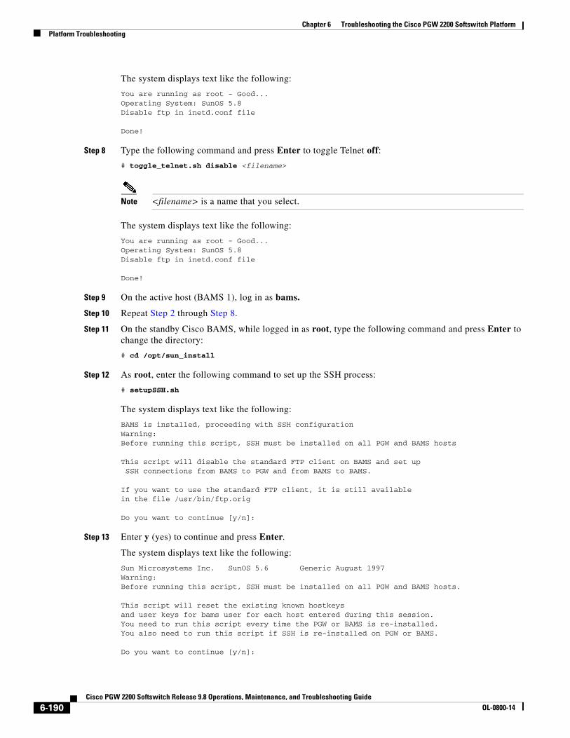
Chapter 6 Troubleshooting the Cisco PGW 2200 Softswitch PlatformPlatform Troubleshooting
The system displays text like the following:
You are running as root - Good...Operating System: SunOS 5.8Disable ftp in inetd.conf file
Done!
Step 8 Type the following command and press Enter to toggle Telnet off:
# toggle_telnet.sh disable <filename>
Note <filename> is a name that you select.
The system displays text like the following:
You are running as root - Good...Operating System: SunOS 5.8Disable ftp in inetd.conf file
Done!
Step 9 On the active host (BAMS 1), log in as bams.
Step 10 Repeat Step 2 through Step 8.
Step 11 On the standby Cisco BAMS, while logged in as root, type the following command and press Enter to change the directory:
# cd /opt/sun_install
Step 12 As root, enter the following command to set up the SSH process:
# setupSSH.sh
The system displays text like the following:
BAMS is installed, proceeding with SSH configurationWarning:Before running this script, SSH must be installed on all PGW and BAMS hosts
This script will disable the standard FTP client on BAMS and set up SSH connections from BAMS to PGW and from BAMS to BAMS.
If you want to use the standard FTP client, it is still availablein the file /usr/bin/ftp.orig
Do you want to continue [y/n]:
Step 13 Enter y (yes) to continue and press Enter.
The system displays text like the following:
Sun Microsystems Inc. SunOS 5.6 Generic August 1997Warning:Before running this script, SSH must be installed on all PGW and BAMS hosts.
This script will reset the existing known hostkeysand user keys for bams user for each host entered during this session.You need to run this script every time the PGW or BAMS is re-installed.You also need to run this script if SSH is re-installed on PGW or BAMS.
Do you want to continue [y/n]:
6-190Cisco PGW 2200 Softswitch Release 9.8 Operations, Maintenance, and Troubleshooting Guide
OL-0800-14

Chapter 6 Troubleshooting the Cisco PGW 2200 Softswitch PlatformPlatform Troubleshooting
Step 14 Enter y (yes) to continue and press Enter.
The system displays text like the following:
Generating security keys, this will take a couple of minutes...Generating public/private rsa key pair.Your identification has been saved in /opt/CiscoBAMS/local/.ssh/id_rsa.Your public key has been saved in /opt/CiscoBAMS/local/.ssh/id_rsa.pub.The key fingerprint is:32:8e:10:10:98:2a:35:8a:18:bb:e6:3e:a1:54:d9:27 bams@va-pineGenerating public/private dsa key pair.Your identification has been saved in /opt/CiscoBAMS/local/.ssh/id_dsa.Your public key has been saved in /opt/CiscoBAMS/local/.ssh/id_dsa.pub.The key fingerprint is:32:dd:2d:51:e3:b4:9b:41:29:49:1a:f2:49:6f:e4:29 bams@va-pine
You will be prompted for the user name and password for each PGWor BAMS host.Please remember to enter both PGW host names for a failover pair.You also need to enter the other BAMS host if this is a redundant setup.
Please enter a PGW or BAMS host name, or q to quitEnter a host name now:
Step 15 Enter hostname PGW1 and press Enter.
The system displays text like the following:
Please enter a PGW or BAMS host name, or q to quitEnter a host name now:
Step 16 Enter the hostname mgcusr (the login name of PGW1) and press Enter.
The system displays text like the following:
Are you sure you want to continue connecting (yes/no)? yes
Step 17 Enter y (yes) and press Enter.
The system displays text like the following:
mgcusr@<hostname>'s password: id_dsa.pub 100% |*****************************| 602 00:00
Step 18 Enter the password and press Enter.
The system displays text like the following:
mgcusr@<BAMS 1>'s password:
Step 19 Enter y (yes) again and press Enter.
The system displays text like the following:
mgcusr on <BAMS> successfully configured
Do you want to configure second interface for <BAMS>? n
Step 20 You can answer either y (yes) or n (no):
• Yes (configuring a second interface) is optional. If you answer y, repeat Step 1 through Step 19.
• If you answer no, proceed to Step 21.
6-191Cisco PGW 2200 Softswitch Release 9.8 Operations, Maintenance, and Troubleshooting Guide
OL-0800-14

Chapter 6 Troubleshooting the Cisco PGW 2200 Softswitch PlatformPlatform Troubleshooting
Step 21 Repeat Step 15 through Step 19 for additional Cisco PGW 2200 Softswitch nodes.
The system displays text like the following:
mgcusr on <BAMS1> successfully configured
Do you want to configure second interface for <BAMS1>? n
Step 22 Enter n (no) and press Enter.
The system displays text like the following:
Please enter a PGW or BAMS host name, or q to quitEnter a host name now:
Step 23 Continuing on the standby Cisco BAMS, type the active Cisco BAMS unit information (Cisco BAMS name, Cisco BAMS login password).
Step 24 When all the Cisco BAMS interfaces have been configured, type q to quit and press Enter.
The system displays text like the following:
Done
Note Watch for the following error message. If some hosts are not configured, follow the recommendation in this message.
Failed to configure some hosts. Please check for SSH installation on these hosts and/or the username and password for these hosts.
Step 25 Log in to the active Cisco BAMS as root.
Step 26 Change the directory. Type the following command and press Enter:
# cd /opt/install
Step 27 Enter the following command and press Enter:
# setupSSH.sh
The system displays text like the following:
BAMS is installed, proceeding with SSH configurationWarning:Before running this script, SSH must be installed on all PGW and BAMS hosts
This script will disable the standard FTP client on BAMS and set up SSH connections from BAMS to PGW and from BAMS to BAMS.
If you want to use the standard FTP client, it is still availablein the file /usr/bin/ftp.orig
Do you want to continue [y/n]:
6-192Cisco PGW 2200 Softswitch Release 9.8 Operations, Maintenance, and Troubleshooting Guide
OL-0800-14

Chapter 6 Troubleshooting the Cisco PGW 2200 Softswitch PlatformPlatform Troubleshooting
Step 28 Enter y to continue and press Enter.
The system displays text like the following:
Sun Microsystems Inc. SunOS 5.6 Generic August 1997Warning:Before running this script, SSH must be installed on all PGW and BAMS hosts.
This script will reset the existing known hostkeysand user keys for bams user for each host entered during this session.You need to run this script every time the PGW or BAMS is re-installed.You also need to run this script if SSH is re-installed on PGW or BAMS.
Do you want to continue [y/n]:
Step 29 Enter y (yes) to continue and press Enter.
The system displays text like the following:
Generating security keys, this will take a couple of minutes...Generating public/private rsa key pair.Your identification has been saved in /opt/CiscoBAMS/local/.ssh/id_rsa.Your public key has been saved in /opt/CiscoBAMS/local/.ssh/id_rsa.pub.The key fingerprint is:32:8e:10:10:98:2a:35:8a:18:bb:e6:3e:a1:54:d9:27 bams@va-pineGenerating public/private dsa key pair.Your identification has been saved in /opt/CiscoBAMS/local/.ssh/id_dsa.Your public key has been saved in /opt/CiscoBAMS/local/.ssh/id_dsa.pub.The key fingerprint is:32:dd:2d:51:e3:b4:9b:41:29:49:1a:f2:49:6f:e4:29 bams@va-pine
You will be prompted for the user name and password for each PGWor BAMS host.Please remember to enter both PGW host names for a failover pair.You also need to enter the other BAMS host if this is a redundant setup.
Please enter a PGW or BAMS host name, or q to quitEnter a host name now:
Step 30 Enter hostname PGW1 and press Enter.
The system displays text like the following:
Please enter a PGW or BAMS host name, or q to quitEnter a host name now:
Step 31 Enter the hostname mgcusr (the login name of PGW1) and press Enter.
The system displays text like the following:
Are you sure you want to continue connecting (yes/no)? yes
Step 32 Enter y (yes) and press Enter.
The system displays text like the following:
mgcusr@<hostname>’s password: id_dsa.pub 100% |*****************************| 602 00:00
Type the password and press Enter.
The system displays text like the following:
mgcusr@<BAMS 1>'s password:
6-193Cisco PGW 2200 Softswitch Release 9.8 Operations, Maintenance, and Troubleshooting Guide
OL-0800-14

Chapter 6 Troubleshooting the Cisco PGW 2200 Softswitch PlatformPlatform Troubleshooting
Step 33 Enter y (yes) again and press Enter.
The system displays text like the following:
mgcusr on <BAMS> successfully configured
Do you want to configure second interface for <BAMS>? n
Step 34 You can answer either y (yes) or n (no):
• Yes (configuring a second interface) is optional. If you answer y, repeat Step 1 through Step 19.
• If you answer no, proceed to Step 21.
Step 35 Repeat Step 15 through Step 19 for additional Cisco PGW 2200 Softswitch nodes.
The system displays text like the following:
mgcusr on <BAMS1> successfully configured
Do you want to configure second interface for <BAMS1>? n
Step 36 Enter n (no) and press Enter.
The system displays text like the following:
Please enter a PGW or BAMS host name, or q to quitEnter a host name now:
Step 37 Continuing on the active Cisco BAMS, enter the standby Cisco BAMS unit information (Cisco BAMS name, Cisco BAMS login password).
Step 38 When all the Cisco BAMS interfaces are configured, type q to quit and press Enter.
The system displays text like the following:
Done
Step 39 Go to the active Cisco PGW 2200 Softswitch (Host A) in the “Securing the Cisco PGW 2200 Softswitch” section on page 6-187 and repeat Step 1 and Step 2.
The system displays text like the following:
-rw-rw-r-- 1 mgcusr mgcgrp 182 Feb 12 14:29 cdr_20030212142403_037281.finished-rw-rw-r-- 1 mgcusr mgcgrp 182 Feb 12 14:34 cdr_20030212142903_037282.finished-rw-rw-r-- 1 mgcusr mgcgrp 182 Feb 12 14:39 cdr_20030212143403_037283.finished-rw-rw-r-- 1 mgcusr mgcgrp 182 Feb 12 14:44 cdr_20030212143903_037284.finished-rw-rw-r-- 1 mgcusr mgcgrp 182 Feb 12 14:49 cdr_20030212144403_037285.finished-rw-rw-r-- 1 mgcusr mgcgrp 182 Feb 12 14:54 cdr_20030212144903_037286.finished-rw-rw-r-- 1 mgcusr mgcgrp 182 Feb 12 14:59 cdr_20030212145403_037287.finished-rw-rw-r-- 1 mgcusr mgcgrp 182 Feb 12 15:04 cdr_20030212145903_037288.finished-rw-rw-r-- 1 mgcusr mgcgrp 182 Feb 12 15:09 cdr_20030212150403_037289.finished-rw-rw-r-- 1 mgcusr mgcgrp 182 Feb 12 15:14 cdr_20030212150903_037290.finished-rw-rw-r-- 1 mgcusr mgcgrp 182 Feb 12 15:19 cdr_20030212151403_037291.bin-rw-rw-r-- 1 mgcusr mgcgrp 182 Feb 12 15:24 cdr_20030212151904_037292.bin-rw-rw-r-- 1 mgcusr mgcgrp 182 Feb 12 15:30 cdr_20030212152434_037293.bin-rw-rw-r-- 1 mgcusr mgcgrp 182 Feb 12 15:35 cdr_20030212153004_037294.bin-rw-rw-r-- 1 mgcusr mgcgrp 182 Feb 12 15:40 cdr_20030212153504_037295.bin-rw-rw-r-- 1 mgcusr mgcgrp 182 Feb 12 15:45 cdr_20030212154004_037296.bin-rw-rw-r-- 1 mgcusr mgcgrp 182 Feb 12 15:50 cdr_20030212154504_037297.bin-rw-rw-r-- 1 mgcusr mgcgrp 182 Feb 12 15:55 cdr_20030212155004_037298.bin
Step 40 Ensure that the CDR file number you noted in Step 3 has changed from .bin to .finished.
6-194Cisco PGW 2200 Softswitch Release 9.8 Operations, Maintenance, and Troubleshooting Guide
OL-0800-14

Chapter 6 Troubleshooting the Cisco PGW 2200 Softswitch PlatformPlatform Troubleshooting
Step 41 Check for alarms on the Cisco BAMS. Enter the following command and press Enter:
<bams hostname> rtrv-alms
The system displays text like the following:
Billing and Measurements Server - BAMS-00 2003-02-12 16:02:08B RTRV02/12/03 15:02:36 *C POL402: Cannot connect to unit <bams1 hostname>02/12/03 15:04:46 *C POL402: Cannot connect to unit <bams2 hostname> ;B COMPLD
Note The CDR file POL402 (which indicates the presence of an alarm that is shown in Step 4) for the active Cisco PGW 2200 Softswitch and standby Cisco BAMS should be gone.
Step 42 Verify that both BAMS 1 and BAMS 2 are communicating with each other.
CDR file POL329 indicates that the active Cisco BAMS (BAMS 1) is sending information to the standby Cisco BAMS (BAMS 2).
Note Because Cisco BAMS polls the Cisco PGW 2200 Softswitch at regular intervals, you might continue to see an alarm for a while. When you do, wait a few minutes and check the logs (see Step 43).
Step 43 To check the logs for alarms (the log name within this directory is syslog), change directory to the following:
# cd /opt/CiscoBAMS/files/s0x
Note x in s0x is the current node in which you are operating.
The process for securing your network is now complete.
TIBCO Interface Not WorkingThe TIBCO interface enables you to use a TIBCO management system to add, modify, delete, and retrieve provisioning data from the Cisco PGW 2200 Softswitch. If you are experiencing difficulties with the TIBCO interface, perform the following steps:
Step 1 If you have not already collected system data, refer to the method that is described in the “Collecting System Data for Cisco TAC” section on page 6-93.
6-195Cisco PGW 2200 Softswitch Release 9.8 Operations, Maintenance, and Troubleshooting Guide
OL-0800-14
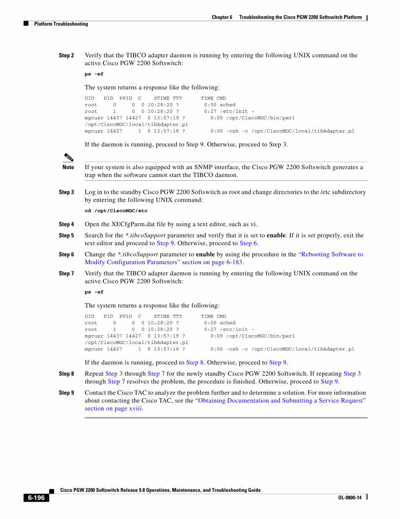
Chapter 6 Troubleshooting the Cisco PGW 2200 Softswitch PlatformPlatform Troubleshooting
Step 2 Verify that the TIBCO adapter daemon is running by entering the following UNIX command on the active Cisco PGW 2200 Softswitch:
ps -ef
The system returns a response like the following:
UID PID PPID C STIME TTY TIME CMDroot 0 0 0 10:28:20 ? 0:00 schedroot 1 0 0 10:28:20 ? 0:27 /etc/init -mgcusr 14437 14427 0 13:57:19 ? 0:00 /opt/CiscoMGC/bin/perl /opt/CiscoMGC/local/tibAdapter.plmgcusr 14427 1 0 13:57:18 ? 0:00 -csh -c /opt/CiscoMGC/local/tibAdapter.pl
If the daemon is running, proceed to Step 9. Otherwise, proceed to Step 3.
Note If your system is also equipped with an SNMP interface, the Cisco PGW 2200 Softswitch generates a trap when the software cannot start the TIBCO daemon.
Step 3 Log in to the standby Cisco PGW 2200 Softswitch as root and change directories to the /etc subdirectory by entering the following UNIX command:
cd /opt/CiscoMGC/etc
Step 4 Open the XECfgParm.dat file by using a text editor, such as vi.
Step 5 Search for the *.tibcoSupport parameter and verify that it is set to enable. If it is set properly, exit the text editor and proceed to Step 9. Otherwise, proceed to Step 6.
Step 6 Change the *.tibcoSupport parameter to enable by using the procedure in the “Rebooting Software to Modify Configuration Parameters” section on page 6-183.
Step 7 Verify that the TIBCO adapter daemon is running by entering the following UNIX command on the active Cisco PGW 2200 Softswitch:
ps -ef
The system returns a response like the following:
UID PID PPID C STIME TTY TIME CMDroot 0 0 0 10:28:20 ? 0:00 schedroot 1 0 0 10:28:20 ? 0:27 /etc/init -mgcusr 14437 14427 0 13:57:19 ? 0:00 /opt/CiscoMGC/bin/perl /opt/CiscoMGC/local/tibAdapter.plmgcusr 14427 1 0 13:57:18 ? 0:00 -csh -c /opt/CiscoMGC/local/tibAdapter.pl
If the daemon is running, proceed to Step 8. Otherwise, proceed to Step 9.
Step 8 Repeat Step 3 through Step 7 for the newly standby Cisco PGW 2200 Softswitch. If repeating Step 3 through Step 7 resolves the problem, the procedure is finished. Otherwise, proceed to Step 9.
Step 9 Contact the Cisco TAC to analyze the problem further and to determine a solution. For more information about contacting the Cisco TAC, see the “Obtaining Documentation and Submitting a Service Request” section on page xviii.
6-196Cisco PGW 2200 Softswitch Release 9.8 Operations, Maintenance, and Troubleshooting Guide
OL-0800-14

Chapter 6 Troubleshooting the Cisco PGW 2200 Softswitch PlatformPlatform Troubleshooting
Installing the License FileSee the detailed procedure in Chapter 3, “Installing Cisco PGW 2200 Softswitch Software,” in the Cisco PGW 2200 Softswitch Release 9.8 Software Installation and Configuration Guide:
http://www.cisco.com/en/US/docs/voice_ip_comm/pgw/9.8/Installation/Guide/Install98.html
Replacing a Failed DiskThis section describes the process for replacing a defective Cisco PGW 2200 Softswitch disk. Each Cisco Cisco PGW 2200 Softswitch system element contains two hard disks (disk 0 and disk 1) that are mirrored using Sun Solaris Disk Suite. You must disable the disk mirroring application between the two disks to replace the defective disk.
Before you start to replace a disk, you must complete the following procedures:
• Identify the disk that must be replaced by viewing the /var/adm/messages.
• The new disk part number must be the same as the defective disk and the size of the replacement disk must be equal to the good disk.
To replace a failed disk on Cisco PGW 2200 Softswitch, perform the following procedure:
Step 1 Enter the following command and press Enter to check the status of DiskSuite objects.
# metastat -i
The system displays text like the following:
d12: Mirror Submirror 0: d10 State: Okay Submirror 1: d11 State: Needs maintenance Pass: 1 Read option: roundrobin (default) Write option: parallel (default) Size: 259963830 blocks (123 GB)
d10: Submirror of d12 State: Okay Size: 259963830 blocks (123 GB) Stripe 0: Device Start Block Dbase State Reloc Hot Spare c3t0d0s5 0 No Okay Yes
d11: Submirror of d12 State: Needs maintenance Invoke: metareplace d12 c3t1d0s5 <new device> Size: 259963830 blocks (123 GB)Stripe 0:
Device Start Block Dbase State Reloc Hot Spare c3t1d0s5 0 No Maintenance Yes
d9: Mirror Submirror 0: d7 State: Okay Submirror 1: d8
6-197Cisco PGW 2200 Softswitch Release 9.8 Operations, Maintenance, and Troubleshooting Guide
OL-0800-14

Chapter 6 Troubleshooting the Cisco PGW 2200 Softswitch PlatformPlatform Troubleshooting
State: Needs maintenance Pass: 1 Read option: roundrobin (default) Write option: parallel (default) Size: 8193150 blocks (3.9 GB)
d7: Submirror of d9 State: Okay Size: 8193150 blocks (3.9 GB) Stripe 0: Device Start Block Dbase State Reloc Hot Spare c3t0d0s3 0 No Okay Yes
d8: Submirror of d9 State: Needs maintenance Invoke: metareplace d9 c3t1d0s3 <new device> Size: 8193150 blocks (3.9 GB) Stripe 0: Device Start Block Dbase State Reloc Hot Spare c3t1d0s3 0 No Maintenance Yes
d6: Mirror Submirror 0: d4 State: Okay Submirror 1: d5 State: Needs maintenance Pass: 1 Read option: roundrobin (default) Write option: parallel (default)Size: 10249470 blocks (4.9 GB)
d4: Submirror of d6 State: Okay Size: 10249470 blocks (4.9 GB) Stripe 0: Device Start Block Dbase State Reloc Hot Spare c3t0d0s1 0 No Okay Yes
d5: Submirror of d6 State: Needs maintenance Invoke: metareplace d6 c3t1d0s1 <new device> Size: 10249470 blocks (4.9 GB) Stripe 0: Device Start Block Dbase State Reloc Hot Spare c3t1d0s1 0 No Maintenance Yes
d3: Mirror Submirror 0: d1 State: Okay Submirror 1: d2 State: Needs maintenance Pass: 1 Read option: roundrobin (default) Write option: parallel (default) Size: 4096575 blocks (2.0 GB)
d1: Submirror of d3 State: Okay Size: 4096575 blocks (2.0 GB)
6-198Cisco PGW 2200 Softswitch Release 9.8 Operations, Maintenance, and Troubleshooting Guide
OL-0800-14

Chapter 6 Troubleshooting the Cisco PGW 2200 Softswitch PlatformPlatform Troubleshooting
Stripe 0: Device Start Block Dbase State Reloc Hot Spare c3t0d0s0 0 No Okay Yes
d2: Submirror of d3 State: Needs maintenance Invoke: metareplace d3 c3t1d0s0 <new device>Size: 4096575 blocks (2.0 GB)
Stripe 0: Device Start Block Dbase State Reloc Hot Spare c3t1d0s0 0 No Maintenance Yes
d15: Mirror Submirror 0: d13 State: Okay Submirror 1: d14 State: Needs maintenance Pass: 1 Read option: roundrobin (default) Write option: parallel (default) Size: 4096575 blocks (2.0 GB)
d13: Submirror of d15 State: Okay Size: 4096575 blocks (2.0 GB) Stripe 0: Device Start Block Dbase State Reloc Hot Spare c3t0d0s6 0 No Okay Yes
d14: Submirror of d15 State: Needs maintenance Invoke: metareplace d15 c3t1d0s6 <new device> Size: 4096575 blocks (2.0 GB) Stripe 0: Device Start Block Dbase State Reloc Hot Spare c3t1d0s6 0 No Maintenance Yes
Device Relocation Information:Device Reloc Device IDc3t1d0 Yes id1,sd@n5000c5000914e78bc3t0d0 Yes id1,sd@n5000c50008cc7c13
Step 2 Delete state database replicas (indicated with State: Needs maintenance) of the defective disk by using the following command:
# metadb -d c3t1d0s4
Step 3 Reboot the Cisco PGW 2200 Softswitch.
# reboot -- -r
Step 4 Remove the defective disk from the Cisco PGW 2200 Softswitch.
Step 5 Insert the new disk into the Cisco PGW 2200 Softswitch.
Step 6 Detect the new disk by issuing the following command:
# devfsadm
6-199Cisco PGW 2200 Softswitch Release 9.8 Operations, Maintenance, and Troubleshooting Guide
OL-0800-14

Chapter 6 Troubleshooting the Cisco PGW 2200 Softswitch PlatformPlatform Troubleshooting
Step 7 Display the available disk information by issuing the following command:
# format
The system displays text like the following:
(Use Ctrl-C to exit.)
Searching for disks...done
AVAILABLE DISK SELECTIONS: 0. c3t0d0 <DEFAULT cyl 17845 alt 2 hd 255 sec 63> /pci@79,0/pci1022,7458@11/pci1000,3060@2/sd@0,0 1. c3t1d0 <DEFAULT cyl 17845 alt 2 hd 255 sec 63> /pci@79,0/pci1022,7458@11/pci1000,3060@2/sd@1,0Specify disk (enter its number):
Step 8 Enter the following command to check the status of DiskSuite objects.
# metastat -i
The system displays text like the following:
d12: Mirror Submirror 0: d10 State: Okay Submirror 1: d11 State: Needs maintenance Pass: 1 Read option: roundrobin (default) Write option: parallel (default) Size: 259963830 blocks (123 GB)
d10: Submirror of d12 State: Okay Size: 259963830 blocks (123 GB) Stripe 0: Device Start Block Dbase State Reloc Hot Spare c3t0d0s5 0 No Okay Yes
d11: Submirror of d12 State: Needs maintenance Invoke: metareplace d12 c3t1d0s5 <new device> Size: 259963830 blocks (123 GB)Stripe 0:
Device Start Block Dbase State Reloc Hot Spare c3t1d0s5 0 No Maintenance Yes
d9: Mirror Submirror 0: d7 State: Okay Submirror 1: d8 State: Needs maintenance Pass: 1 Read option: roundrobin (default) Write option: parallel (default) Size: 8193150 blocks (3.9 GB)
d7: Submirror of d9 State: Okay Size: 8193150 blocks (3.9 GB)
6-200Cisco PGW 2200 Softswitch Release 9.8 Operations, Maintenance, and Troubleshooting Guide
OL-0800-14
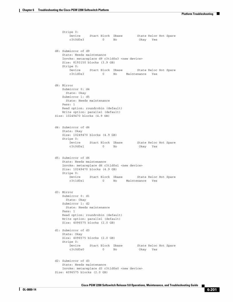
Chapter 6 Troubleshooting the Cisco PGW 2200 Softswitch PlatformPlatform Troubleshooting
Stripe 0: Device Start Block Dbase State Reloc Hot Spare c3t0d0s3 0 No Okay Yes
d8: Submirror of d9 State: Needs maintenance Invoke: metareplace d9 c3t1d0s3 <new device> Size: 8193150 blocks (3.9 GB) Stripe 0: Device Start Block Dbase State Reloc Hot Spare c3t1d0s3 0 No Maintenance Yes
d6: Mirror Submirror 0: d4 State: Okay Submirror 1: d5 State: Needs maintenance Pass: 1 Read option: roundrobin (default) Write option: parallel (default)Size: 10249470 blocks (4.9 GB)
d4: Submirror of d6 State: Okay Size: 10249470 blocks (4.9 GB) Stripe 0: Device Start Block Dbase State Reloc Hot Spare c3t0d0s1 0 No Okay Yes
d5: Submirror of d6 State: Needs maintenance Invoke: metareplace d6 c3t1d0s1 <new device> Size: 10249470 blocks (4.9 GB) Stripe 0: Device Start Block Dbase State Reloc Hot Spare c3t1d0s1 0 No Maintenance Yes
d3: Mirror Submirror 0: d1 State: Okay Submirror 1: d2 State: Needs maintenance Pass: 1 Read option: roundrobin (default) Write option: parallel (default) Size: 4096575 blocks (2.0 GB)
d1: Submirror of d3 State: Okay Size: 4096575 blocks (2.0 GB) Stripe 0: Device Start Block Dbase State Reloc Hot Spare c3t0d0s0 0 No Okay Yes
d2: Submirror of d3 State: Needs maintenance Invoke: metareplace d3 c3t1d0s0 <new device>Size: 4096575 blocks (2.0 GB)
6-201Cisco PGW 2200 Softswitch Release 9.8 Operations, Maintenance, and Troubleshooting Guide
OL-0800-14

Chapter 6 Troubleshooting the Cisco PGW 2200 Softswitch PlatformPlatform Troubleshooting
Stripe 0: Device Start Block Dbase State Reloc Hot Spare c3t1d0s0 0 No Maintenance Yes
d15: Mirror Submirror 0: d13 State: Okay Submirror 1: d14 State: Needs maintenance Pass: 1 Read option: roundrobin (default) Write option: parallel (default) Size: 4096575 blocks (2.0 GB)
d13: Submirror of d15 State: Okay Size: 4096575 blocks (2.0 GB) Stripe 0: Device Start Block Dbase State Reloc Hot Spare c3t0d0s6 0 No Okay Yes
d14: Submirror of d15 State: Needs maintenance Invoke: metareplace d15 c3t1d0s6 <new device> Size: 4096575 blocks (2.0 GB) Stripe 0: Device Start Block Dbase State Reloc Hot Spare c3t1d0s6 0 No Maintenance Yes
Device Relocation Information:Device Reloc Device IDc3t0d0 Yes id1,sd@n5000c50008cc7c13
Step 9 Import the volume table of contents from the existing disk to the new disk using the following command:
# prtvtoc /dev/rdsk/c3t0d0s2 | fmthard -s - /dev/rdsk/c3t1d0s2
Text similar to the following is displayed:
fmthard: New volume table of contents now in place.
Make the new disk bootable with the following command:
# fdisk -b /usr/lib/fs/ufs/mboot /dev/rdsk/c3t1d0p0
Text similar to the following is displayed:
No fdisk table exists. The default partition for the disk is: a 100% "SOLARIS System" partitionType "y" to accept the default partition, otherwise type "n" to edit the partition table.
Enter y to accept the default partition, and text similar to the following is displayed:
# /sbin/installgrub /boot/grub/stage1 /boot/grub/stage2 /dev/rdsk/c3t1d0s0stage1 written to partition 0 sector 0 (abs 16065)stage2 written to partition 0, 232 sectors starting at 50 (abs 16115)
Step 10 Create the initial state database by issuing the following command:
# metadb -f -a /dev/dsk/c3t1d0s4
6-202Cisco PGW 2200 Softswitch Release 9.8 Operations, Maintenance, and Troubleshooting Guide
OL-0800-14

Chapter 6 Troubleshooting the Cisco PGW 2200 Softswitch PlatformPlatform Troubleshooting
Step 11 Display the status of the disk state databases by issuing the following command:
# metadb -i
The system displays text like the following:
flags first blk block count a m p luo 16 8192 /dev/dsk/c3t0d0s4 a u 16 8192 /dev/dsk/c3t1d0s4 r - replica does not have device relocation information o - replica active prior to last mddb configuration change u - replica is up to date l - locator for this replica was read successfully c - replica's location was in /etc/lvm/mddb.cf p - replica's location was patched in kernel m - replica is master, this is replica selected as input W - replica has device write errors a - replica is active, commits are occurring to this replica M - replica had problem with master blocks D - replica had problem with data blocks F - replica had format problems S - replica is too small to hold current data base R - replica had device read errors
Step 12 Enter the following commands to enable the mirror and submirror components that require maintenance (shown in Step 8).
# metareplace -e d15 c3t1d0s6# metareplace -e d12 c3t1d0s5# metareplace -e d9 c3t1d0s3# metareplace -e d6 c3t1d0s1# metareplace -e d3 c3t1d0s0
Step 13 Verify that the status of DiskSuite objects is okay using the following command:
# metastat -i
The system displays text like the following:
d12: Mirror Submirror 0: d10 State: Okay Submirror 1: d11 State: Okay Pass: 1 Read option: roundrobin (default) Write option: parallel (default) Size: 259963830 blocks (123 GB)
d10: Submirror of d12 State: Okay Size: 259963830 blocks (123 GB) Stripe 0: Device Start Block Dbase State Reloc Hot Spare c3t0d0s5 0 No Okay Yes
d11: Submirror of d12 State: Okay Size: 259963830 blocks (123 GB) Stripe 0: Device Start Block Dbase State Reloc Hot Spare c3t1d0s5 0 No Okay Yes
6-203Cisco PGW 2200 Softswitch Release 9.8 Operations, Maintenance, and Troubleshooting Guide
OL-0800-14

Chapter 6 Troubleshooting the Cisco PGW 2200 Softswitch PlatformPlatform Troubleshooting
d9: Mirror Submirror 0: d7 State: Okay Submirror 1: d8 State: Okay Pass: 1 Read option: roundrobin (default) Write option: parallel (default)Size: 8193150 blocks (3.9 GB)
d7: Submirror of d9 State: Okay Size: 8193150 blocks (3.9 GB) Stripe 0: Device Start Block Dbase State Reloc Hot Spare c3t0d0s3 0 No Okay Yes
d8: Submirror of d9 State: Okay Size: 8193150 blocks (3.9 GB) Stripe 0: Device Start Block Dbase State Reloc Hot Spare c3t1d0s3 0 No Okay Yes
d6: Mirror Submirror 0: d4 State: Okay Submirror 1: d5 State: Okay Pass: 1 Read option: roundrobin (default) Write option: parallel (default) Size: 10249470 blocks (4.9 GB)
d4: Submirror of d6 State: Okay Size: 10249470 blocks (4.9 GB) Stripe 0: Device Start Block Dbase State Reloc Hot Spare c3t0d0s1 0 No Okay Yes
d5: Submirror of d6 State: Okay Size: 10249470 blocks (4.9 GB) Stripe 0: Device Start Block Dbase State Reloc Hot Spare c3t1d0s1 0 No Okay Yes
d3: Mirror Submirror 0: d1 State: Okay Submirror 1: d2 State: Okay Pass: 1 Read option: roundrobin (default) Write option: parallel (default) Size: 4096575 blocks (2.0 GB)
d1: Submirror of d3 State: Okay
6-204Cisco PGW 2200 Softswitch Release 9.8 Operations, Maintenance, and Troubleshooting Guide
OL-0800-14

Chapter 6 Troubleshooting the Cisco PGW 2200 Softswitch PlatformPlatform Troubleshooting
Size: 4096575 blocks (2.0 GB) Stripe 0: Device Start Block Dbase State Reloc Hot Spare c3t0d0s0 0 No Okay Yes
d2: Submirror of d3 State: Okay Size: 4096575 blocks (2.0 GB) Stripe 0: Device Start Block Dbase State Reloc Hot Spare c3t1d0s0 0 No Okay Yes
d15: Mirror Submirror 0: d13 State: Okay Submirror 1: d14 State: Okay Pass: 1 Read option: roundrobin (default) Write option: parallel (default) Size: 4096575 blocks (2.0 GB)
d13: Submirror of d15 State: Okay Size: 4096575 blocks (2.0 GB) Stripe 0: Device Start Block Dbase State Reloc Hot Spare c3t0d0s6 0 No Okay Yes
d14: Submirror of d15 State: Okay Size: 4096575 blocks (2.0 GB) Stripe 0: Device Start Block Dbase State Reloc Hot Spare c3t1d0s6 0 No Okay Yes
Device Relocation Information:Device Reloc Device IDc3t1d0 Yes id1,sd@n5000c5000914e78bc3t0d0 Yes id1,sd@n5000c50008cc7c13
6-205Cisco PGW 2200 Softswitch Release 9.8 Operations, Maintenance, and Troubleshooting Guide
OL-0800-14

Chapter 6 Troubleshooting the Cisco PGW 2200 Softswitch PlatformPlatform Troubleshooting
6-206Cisco PGW 2200 Softswitch Release 9.8 Operations, Maintenance, and Troubleshooting Guide
OL-0800-14