tutorial - cemrweb for lamtopo automatic grid generation for lamodel one of the nicest features...
TRANSCRIPT
1
TutorialTutorialFor For LamTopoLamTopo
Automatic Grid Generation for Automatic Grid Generation for LaModelLaModel
One of the nicest features introduced in LaModel 2.0 was the capability of building the seam and topographic grid automatically from AutoCAD files.
The initial versions of the seam and topo grid generators have been significantly enhanced in LaModel 2.1.
This tutorial helps explain the procedure for using these new routines by guiding the user through a sample application.
2
AutoCad
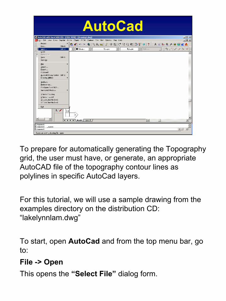
To prepare for automatically generating the Topography grid, the user must have, or generate, an appropriate AutoCAD file of the topography contour lines as polylines in specific AutoCad layers.
For this tutorial, we will use a sample drawing from the examples directory on the distribution CD: “lakelynnlam.dwg”
To start, open AutoCad and from the top menu bar, go to:File -> OpenThis opens the “Select File” dialog form.
3
Selecting the File
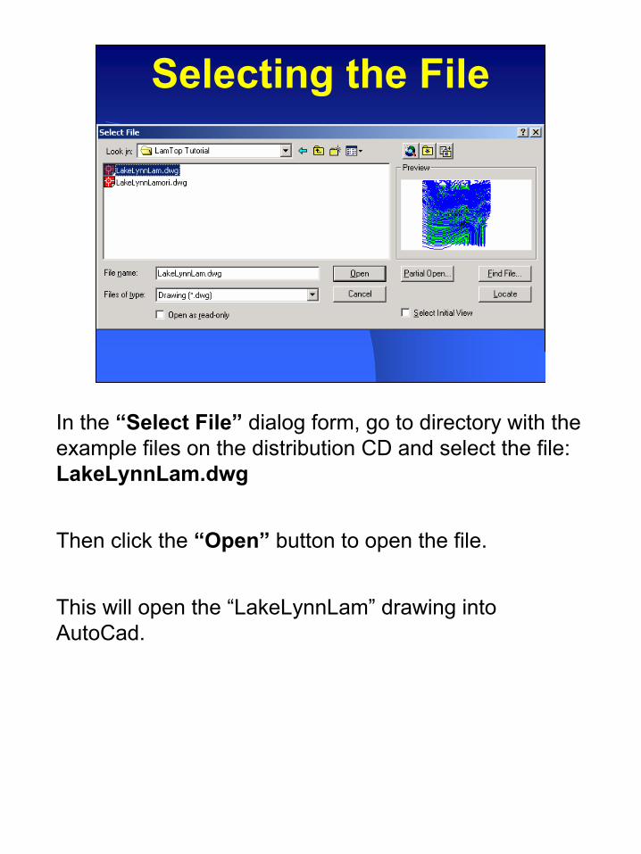
In the “Select File” dialog form, go to directory with the example files on the distribution CD and select the file: LakeLynnLam.dwg
Then click the “Open” button to open the file.
This will open the “LakeLynnLam” drawing into AutoCad.
4
Load LamGrid.arx
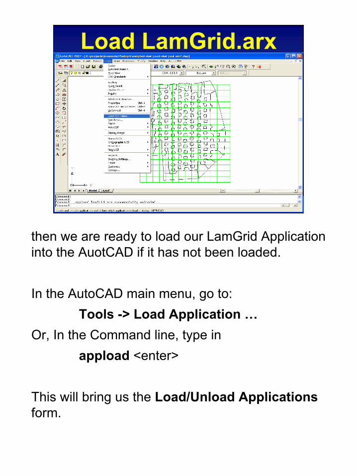
then we are ready to load our LamGrid Application into the AuotCAD if it has not been loaded.
In the AutoCAD main menu, go to:Tools -> Load Application …
Or, In the Command line, type inappload <enter>
This will bring us the Load/Unload Applicationsform.
5
Load LamGrid.arx
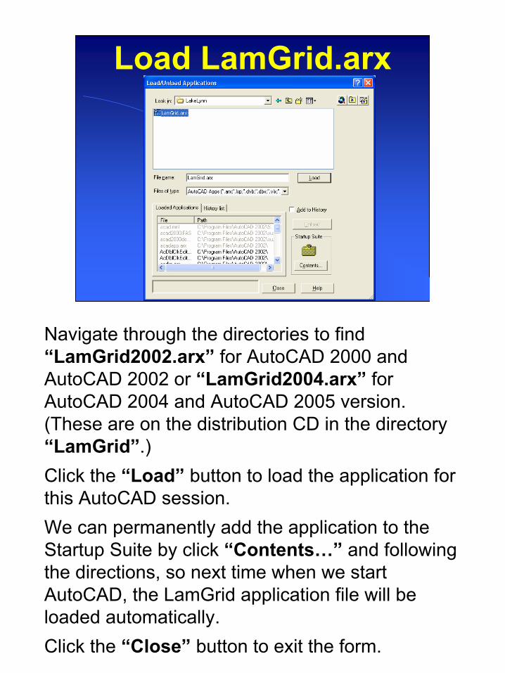
Navigate through the directories to find “LamGrid2002.arx” for AutoCAD 2000 and AutoCAD 2002 or “LamGrid2004.arx” for AutoCAD 2004 and AutoCAD 2005 version. (These are on the distribution CD in the directory “LamGrid”.) Click the “Load” button to load the application for this AutoCAD session.We can permanently add the application to the Startup Suite by click “Contents…” and following the directions, so next time when we start AutoCAD, the LamGrid application file will be loaded automatically.Click the “Close” button to exit the form.

6
LamGrid Menu
After LamGrid is successfully loaded, a pull-down menu named “Grid for LaModel” will be added to the AutoCAD top menu bar. This menu contains 6 menu items: “Seam Grid”, “Topography Grid”, “Join Polylines”, “Close Polylines”, “Move Duplicates” and “Clear Duplicate Polylines”.
Before we start topography generator, we would like to explore the AutoCAD drawing first.
7
LakeLynnLam
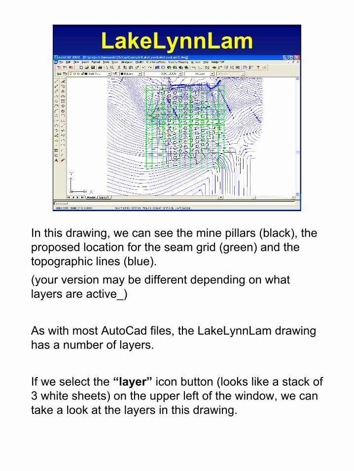
In this drawing, we can see the mine pillars (black), the proposed location for the seam grid (green) and the topographic lines (blue).(your version may be different depending on what layers are active_)
As with most AutoCad files, the LakeLynnLam drawing has a number of layers.
If we select the “layer” icon button (looks like a stack of 3 white sheets) on the upper left of the window, we can take a look at the layers in this drawing.
8
Isolate the Topo Layer
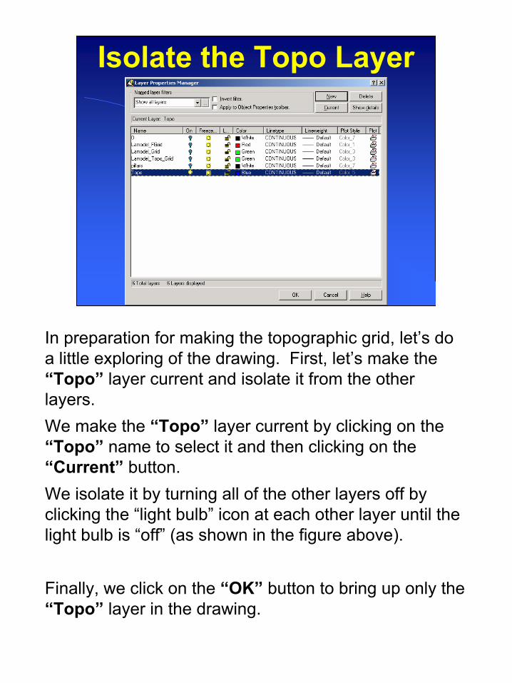
In preparation for making the topographic grid, let’s do a little exploring of the drawing. First, let’s make the “Topo” layer current and isolate it from the other layers.We make the “Topo” layer current by clicking on the “Topo” name to select it and then clicking on the “Current” button.We isolate it by turning all of the other layers off by clicking the “light bulb” icon at each other layer until the light bulb is “off” (as shown in the figure above).
Finally, we click on the “OK” button to bring up only the “Topo” layer in the drawing.
9
Topographic Lines
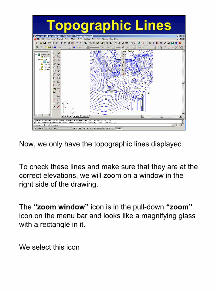
Now, we only have the topographic lines displayed.
To check these lines and make sure that they are at the correct elevations, we will zoom on a window in the right side of the drawing.
The “zoom window” icon is in the pull-down “zoom”icon on the menu bar and looks like a magnifying glass with a rectangle in it.
We select this icon

10
Zoom Window
Now, we need to click the first corner and drag a rectangle and click the second corner of our zoom window as shown in the figure above.
This will zoom in on the rectangular window that we have defined.
11
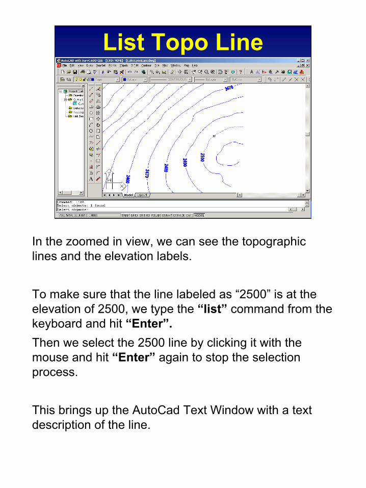
List Topo Line
In the zoomed in view, we can see the topographic lines and the elevation labels.
To make sure that the line labeled as “2500” is at the elevation of 2500, we type the “list” command from the keyboard and hit “Enter”.Then we select the 2500 line by clicking it with the mouse and hit “Enter” again to stop the selection process.
This brings up the AutoCad Text Window with a text description of the line.

12
Elevation Check
In this text window, we can indeed see that all points on the line are at the “Z” coordinate of 2500. (These are the points that the LamTop program will use to interpret the elevation of the grid nodes.)
To leave this window, we hit the “Esc” key to stop the scrolling and then click on the AutoCad main window to bring it on top.
13
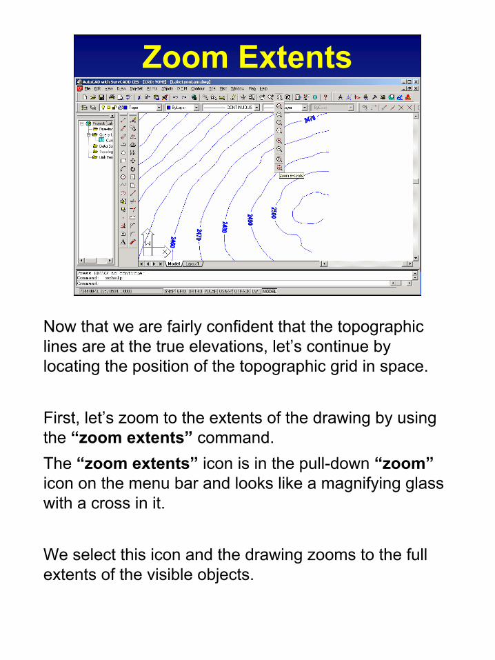
Zoom Extents
Now that we are fairly confident that the topographic lines are at the true elevations, let’s continue by locating the position of the topographic grid in space.
First, let’s zoom to the extents of the drawing by using the “zoom extents” command.The “zoom extents” icon is in the pull-down “zoom”icon on the menu bar and looks like a magnifying glass with a cross in it.
We select this icon and the drawing zooms to the full extents of the visible objects.
14
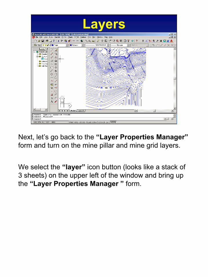
Layers
Next, let’s go back to the “Layer Properties Manager”form and turn on the mine pillar and mine grid layers.
We select the “layer” icon button (looks like a stack of 3 sheets) on the upper left of the window and bring up the “Layer Properties Manager ” form.
15
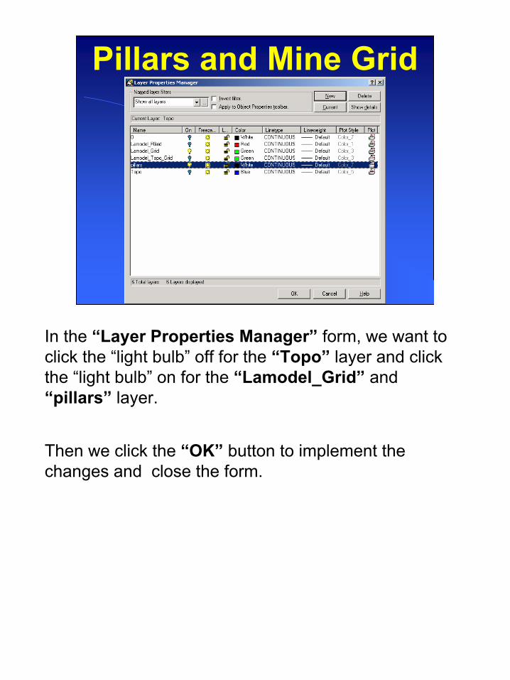
Pillars and Mine Grid
In the “Layer Properties Manager” form, we want to click the “light bulb” off for the “Topo” layer and click the “light bulb” on for the “Lamodel_Grid” and “pillars” layer.
Then we click the “OK” button to implement the changes and close the form.
16
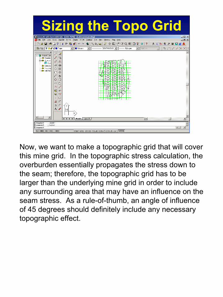
Sizing the Topo Grid
Now, we want to make a topographic grid that will cover this mine grid. In the topographic stress calculation, the overburden essentially propagates the stress down to the seam; therefore, the topographic grid has to be larger than the underlying mine grid in order to include any surrounding area that may have an influence on the seam stress. As a rule-of-thumb, an angle of influence of 45 degrees should definitely include any necessary topographic effect.
17
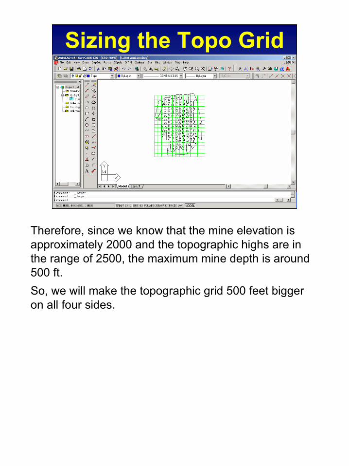
Sizing the Topo Grid
Therefore, since we know that the mine elevation is approximately 2000 and the topographic highs are in the range of 2500, the maximum mine depth is around 500 ft. So, we will make the topographic grid 500 feet bigger on all four sides.
18
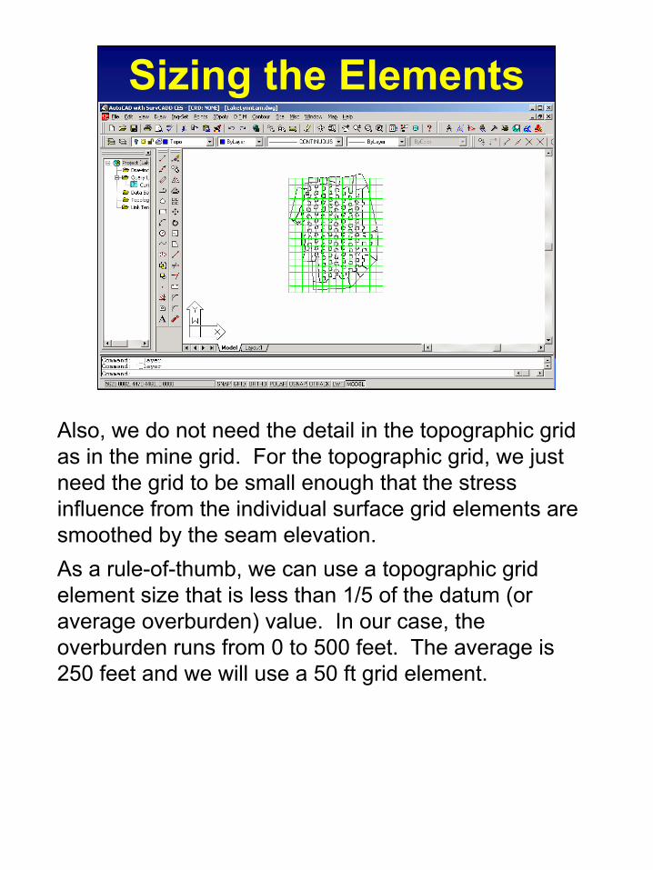
Sizing the Elements
Also, we do not need the detail in the topographic grid as in the mine grid. For the topographic grid, we just need the grid to be small enough that the stress influence from the individual surface grid elements are smoothed by the seam elevation.As a rule-of-thumb, we can use a topographic grid element size that is less than 1/5 of the datum (or average overburden) value. In our case, the overburden runs from 0 to 500 feet. The average is 250 feet and we will use a 50 ft grid element.

19
Topo Grid Data
Since we have a mine grid that is 1400 by 1700 feet and starts at 5350, 3000.
We want our topographic grid to be 500 ft wider on all sides.
So, our topographic grid must be 2400 by 2700 feet and start at coordinates 4850, 2500. With a 50 ft grid element, this grid will have 48 X 54 elements
These are the numbers that we need to remember in building our topographic grid using LamTopo.
20
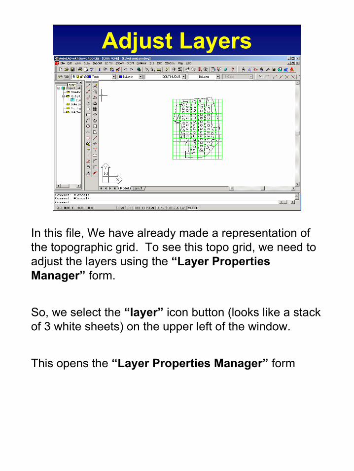
Adjust Layers
In this file, We have already made a representation of the topographic grid. To see this topo grid, we need to adjust the layers using the “Layer Properties Manager” form.
So, we select the “layer” icon button (looks like a stack of 3 white sheets) on the upper left of the window.
This opens the “Layer Properties Manager” form
21
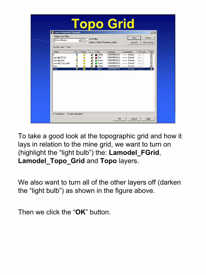
Topo Grid
To take a good look at the topographic grid and how it lays in relation to the mine grid, we want to turn on (highlight the “light bulb”) the: Lamodel_FGrid, Lamodel_Topo_Grid and Topo layers.
We also want to turn all of the other layers off (darken the “light bulb”) as shown in the figure above.
Then we click the “OK” button.
22
Mine and Topo Grids
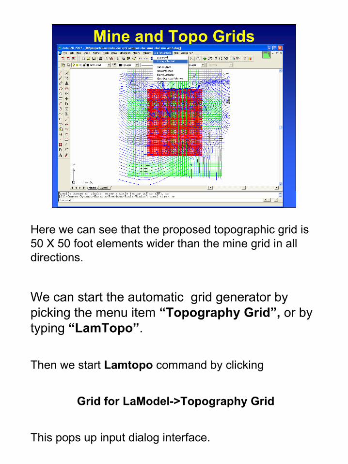
Here we can see that the proposed topographic grid is 50 X 50 foot elements wider than the mine grid in all directions.
We can start the automatic grid generator by picking the menu item “Topography Grid”, or by typing “LamTopo”.
Then we start Lamtopo command by clicking
Grid for LaModel->Topography Grid
This pops up input dialog interface.

23
Topogrid GeneratorPick button
The first tab is similar to the one in seam grid generator.
We can input the coordinate of grid we got before, or we can capture the point by clicking the pick button.
Let’s click the button and it will take us to AutoCAD screen.
24
Grid Location
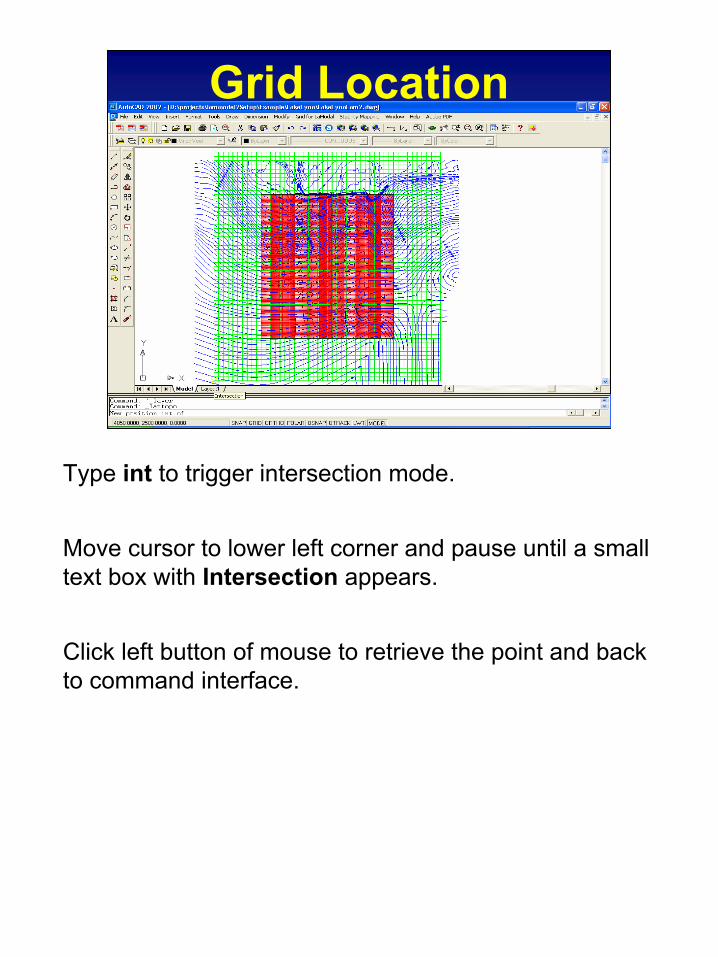
Type int to trigger intersection mode.
Move cursor to lower left corner and pause until a small text box with Intersection appears.
Click left button of mouse to retrieve the point and back to command interface.
25
Gird Defination
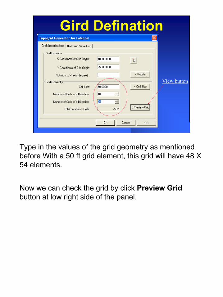
View button
Type in the values of the grid geometry as mentioned before With a 50 ft grid element, this grid will have 48 X 54 elements.
Now we can check the grid by click Preview Gridbutton at low right side of the panel.

26
Here we can see that the new topogrid fits the proposed topographic grid well.
Then we type return key back to interface and look at the build and Save Grid tab by clicking at the top tab line.
27
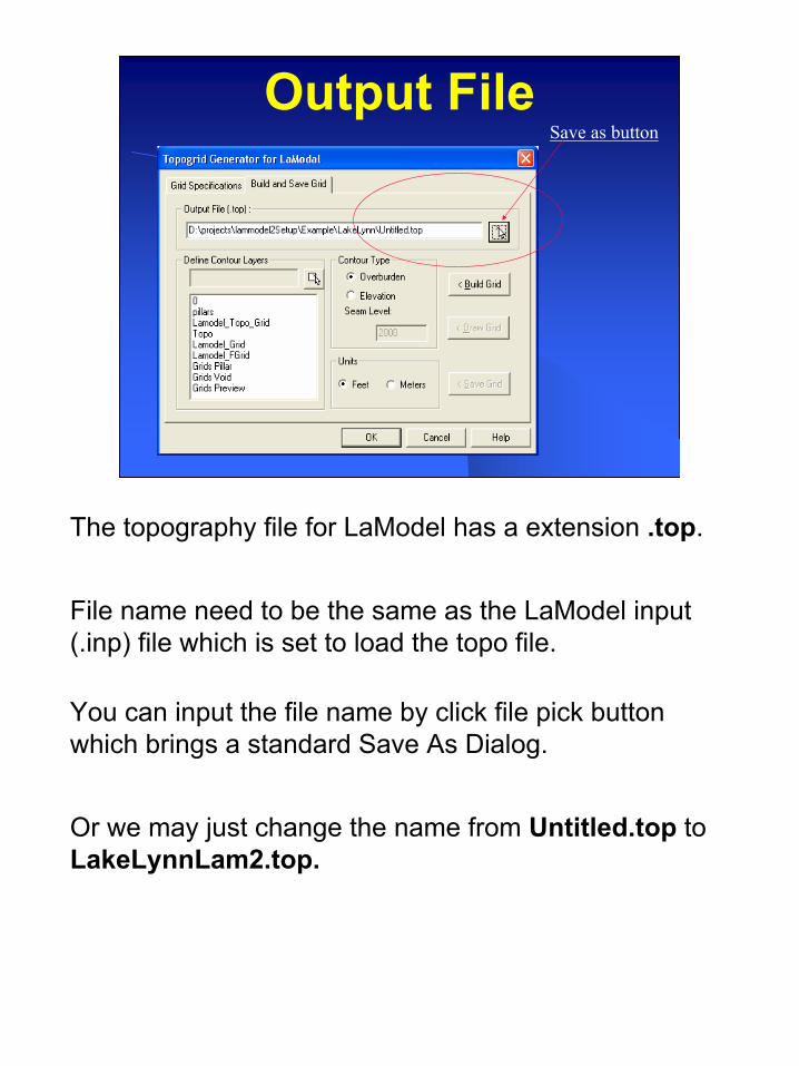
Output FileSave as button
The topography file for LaModel has a extension .top.
File name need to be the same as the LaModel input (.inp) file which is set to load the topo file.
You can input the file name by click file pick button which brings a standard Save As Dialog.
Or we may just change the name from Untitled.top to LakeLynnLam2.top.
28
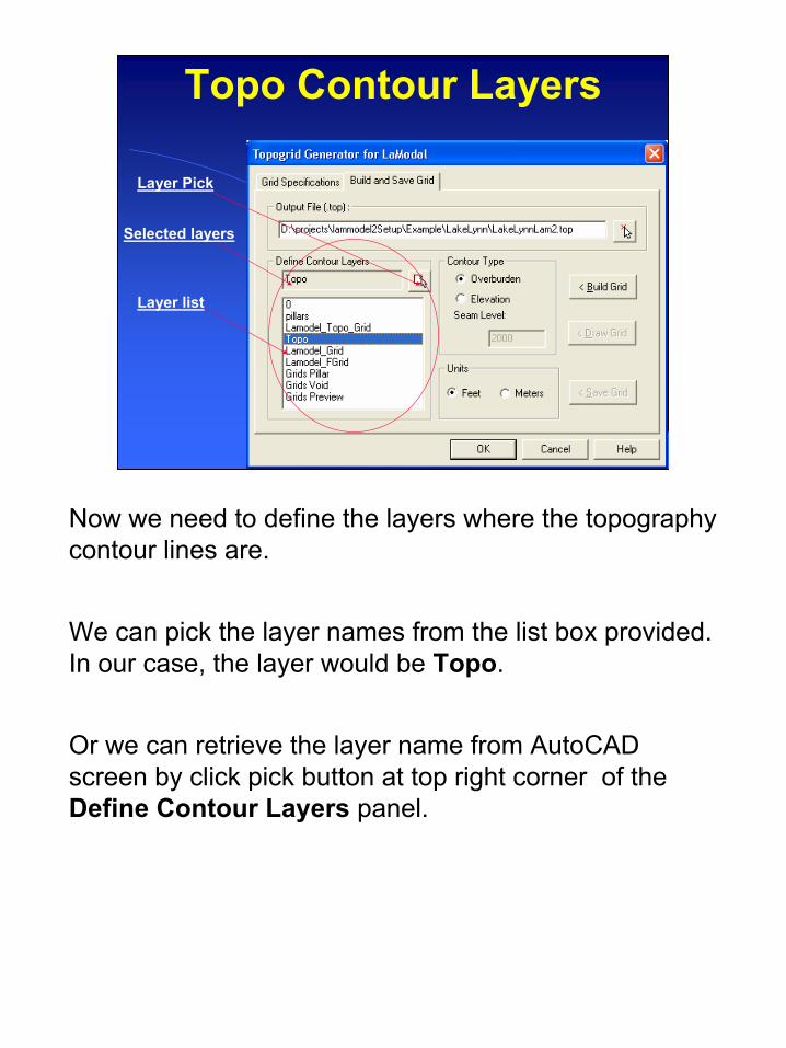
Topo Contour Layers
Selected layers
Layer list
Layer Pick
Now we need to define the layers where the topography contour lines are.
We can pick the layer names from the list box provided. In our case, the layer would be Topo.
Or we can retrieve the layer name from AutoCAD screen by click pick button at top right corner of the Define Contour Layers panel.

29
Pick Contour Layer
In the command line of AutoCAD, the Program will prompt:
Select any object in the layer:
Then in the AutoCAD screen, pick any contour line that represents the topography.

30
Contour Type and Unit
LaModel requires the topo file with the overburden thickness between mine surface and the top seam.
Since the contour lines here represent topography elevation, we need to specify the seam level.
We know the average seam elevation is 2000 feet and input it into the text box.
We leave the units as default Feet that is our case.
Then we are ready to build the topo grid.
To do it, click Build Grid button at the right side.

31
Mine and Topo Grids
At the beginning, the program will temporarily close unrelated layers and report the grid, layer and contour line facts.
You can press <Esc> key to break the process or <Enter> to continue.
32
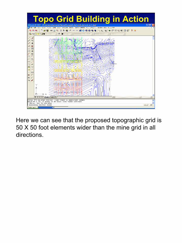
Topo Grid Building in Action
Here we can see that the proposed topographic grid is 50 X 50 foot elements wider than the mine grid in all directions.
33
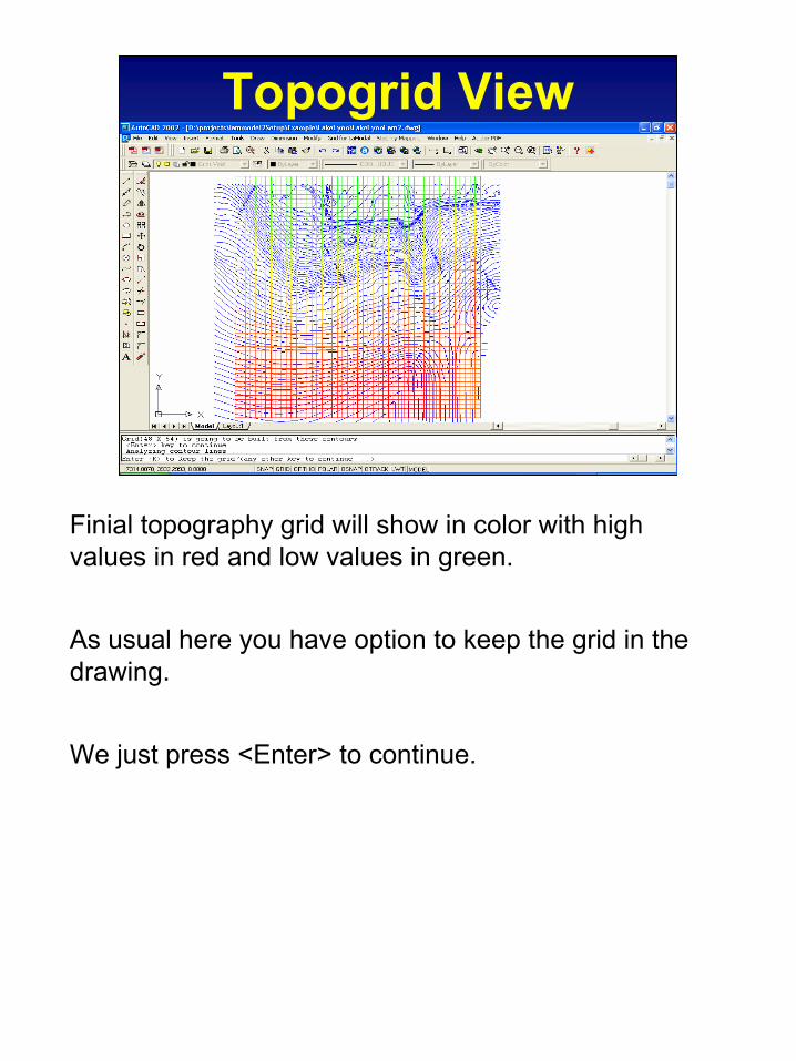
Topogrid View
Finial topography grid will show in color with high values in red and low values in green.
As usual here you have option to keep the grid in the drawing.
We just press <Enter> to continue.
34
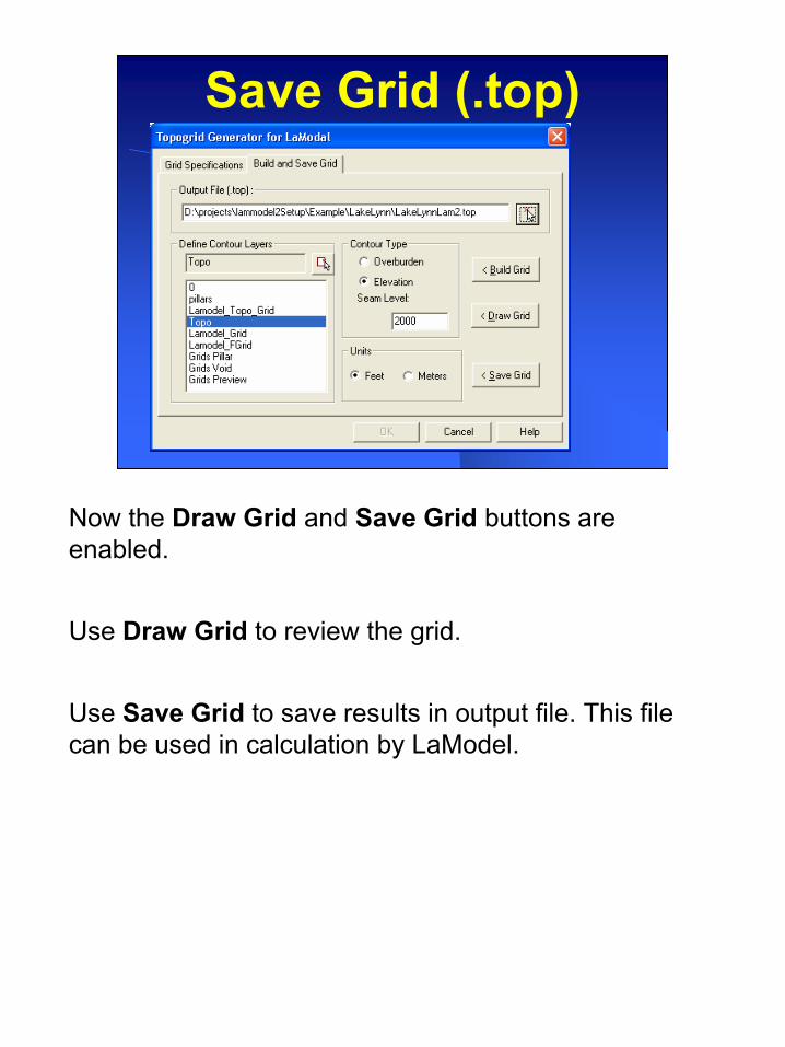
Save Grid (.top)
Now the Draw Grid and Save Grid buttons are enabled.
Use Draw Grid to review the grid.
Use Save Grid to save results in output file. This file can be used in calculation by LaModel.
35
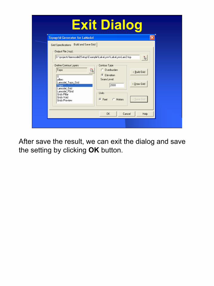
Exit Dialog
After save the result, we can exit the dialog and save the setting by clicking OK button.
36
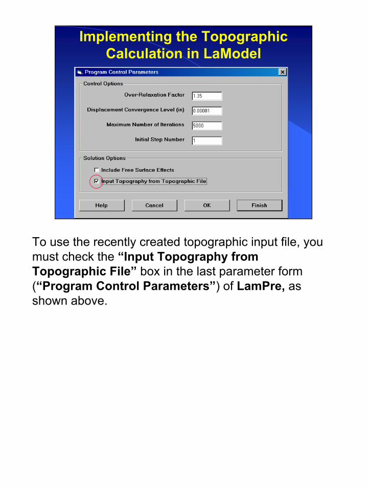
Implementing the Topographic Calculation in LaModel
To use the recently created topographic input file, you must check the “Input Topography from Topographic File” box in the last parameter form (“Program Control Parameters”) of LamPre, as shown above.

37
Consistency of the Coordinate System
Also, you must be careful with your coordinate system in LamPre/LaModel. If you use local grid coordinates in LamPre ( often 0,0 ), you must be consistent in the topographic input file and modify the coordinates of the topographic grid origin in the first line of your .top file. This is necessary since LamTopo naturally uses the world coordinate system in AutoCAD for its calculations and without consistent coordinates between the two files, the topographic grid will not be correctly located in relation to the mine grid.
If you use world coordinates in LamPre for the mine grid, then there is no inconsistency between the input mine grid and the topographic grid.
38
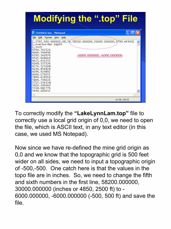
Modifying the “.top” File
-6000.000000,-6000.000000
To correctly modify the “LakeLynnLam.top” file to correctly use a local grid origin of 0,0, we need to open the file, which is ASCII text, in any text editor (in this case, we used MS Notepad).
Now since we have re-defined the mine grid origin as 0,0 and we know that the topographic grid is 500 feet wider on all sides, we need to input a topographic origin of -500,-500. One catch here is that the values in the topo file are in inches. So, we need to change the fifth and sixth numbers in the first line, 58200.000000, 30000.000000 (inches or 4850, 2500 ft) to -6000.000000, -6000.000000 (-500, 500 ft) and save the file.
39
Topography in LaModel
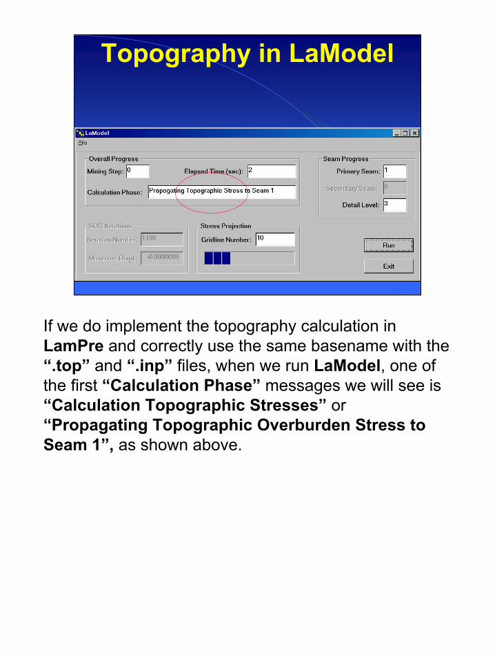
If we do implement the topography calculation in LamPre and correctly use the same basename with the “.top” and “.inp” files, when we run LaModel, one of the first “Calculation Phase” messages we will see is “Calculation Topographic Stresses” or “Propagating Topographic Overburden Stress to Seam 1”, as shown above.
40
Topography in LamPlt
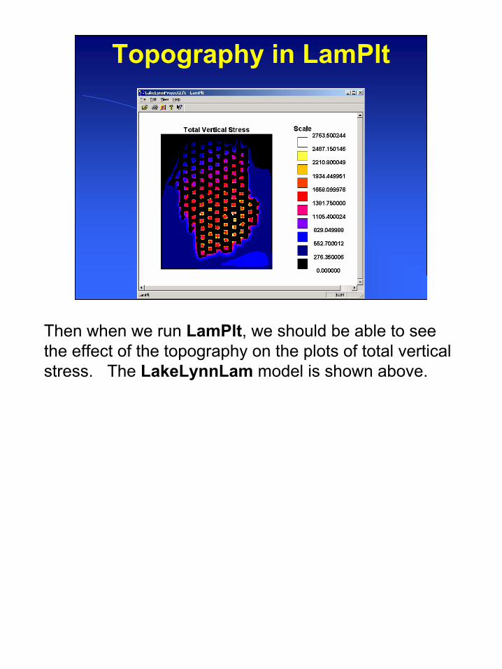
Then when we run LamPlt, we should be able to see the effect of the topography on the plots of total vertical stress. The LakeLynnLam model is shown above.
41
Topography in LamPlt
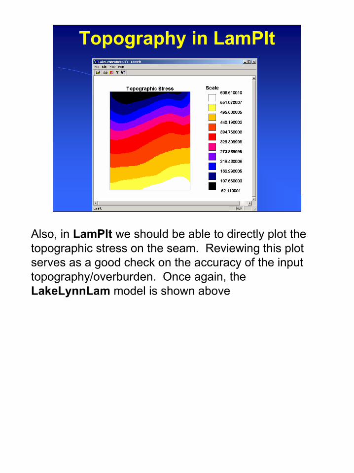
Also, in LamPlt we should be able to directly plot the topographic stress on the seam. Reviewing this plot serves as a good check on the accuracy of the input topography/overburden. Once again, the LakeLynnLam model is shown above
42
Grid Generator from LamPre
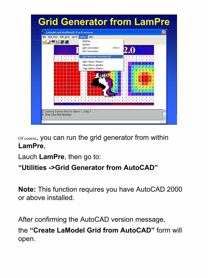
Of course, you can run the grid generator from withinLamPre,Lauch LamPre, then go to:“Utilities ->Grid Generator from AutoCAD”
Note: This function requires you have AutoCAD 2000 or above installed.
After confirming the AutoCAD version message,the “Create LaModel Grid from AutoCAD” form will open.
43
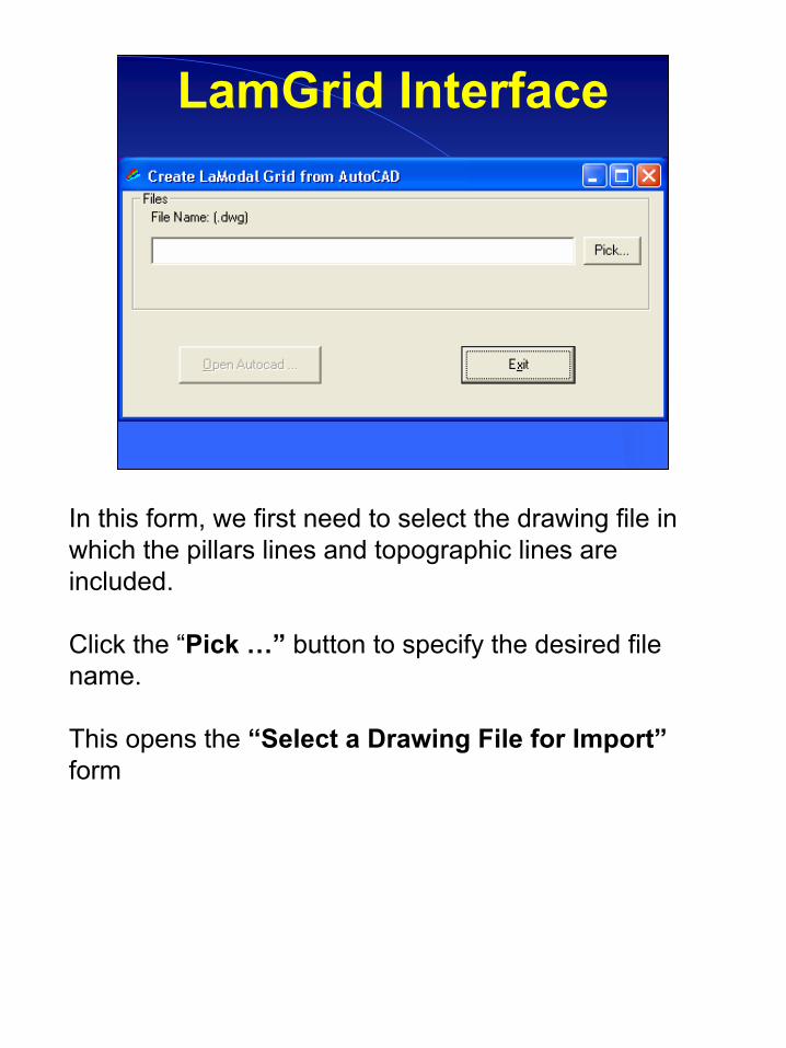
LamGrid Interface
In this form, we first need to select the drawing file in which the pillars lines and topographic lines are included.
Click the “Pick …” button to specify the desired file name.
This opens the “Select a Drawing File for Import”form
44
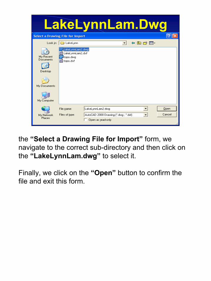
LakeLynnLam.Dwg
the “Select a Drawing File for Import” form, we navigate to the correct sub-directory and then click on the “LakeLynnLam.dwg” to select it.
Finally, we click on the “Open” button to confirm the file and exit this form.
45
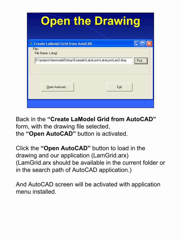
Open the Drawing
Back in the “Create LaModel Grid from AutoCAD”form, with the drawing file selected,the “Open AutoCAD” button is activated.
Click the “Open AutoCAD” button to load in the drawing and our application (LamGrid.arx)(LamGrid.arx should be available in the current folder or in the search path of AutoCAD application.)
And AutoCAD screen will be activated with application menu installed.
46
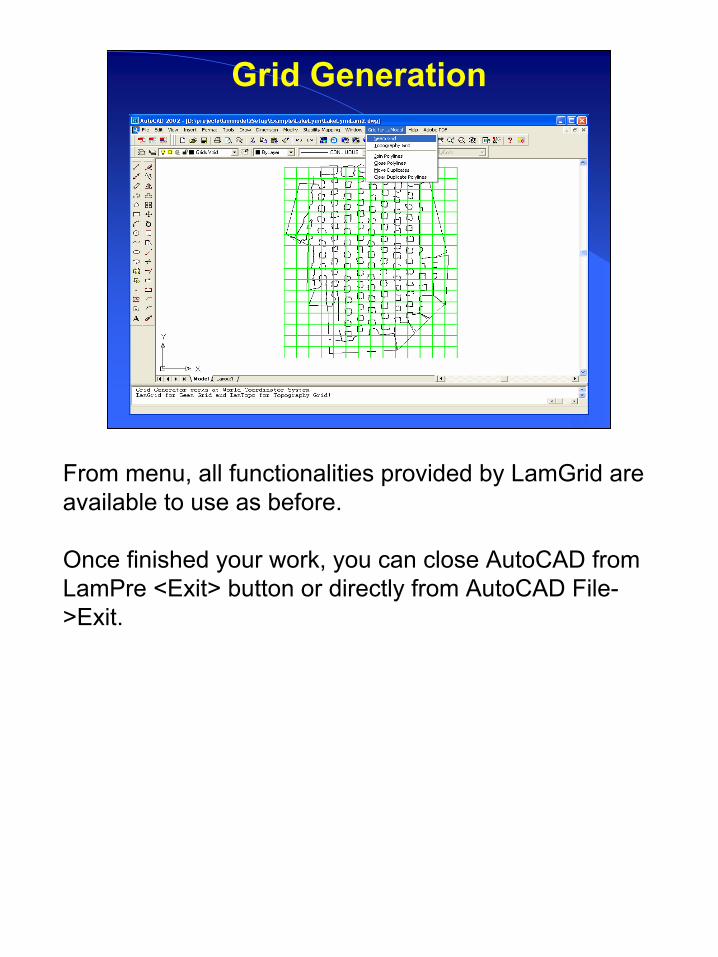
Grid Generation
From menu, all functionalities provided by LamGrid are available to use as before.
Once finished your work, you can close AutoCAD from LamPre <Exit> button or directly from AutoCAD File->Exit.