tutorials - tradeindiaimg.tradeindia.com/fm/148350/tutorials.pdftutorials 1. autocollimator general...
TRANSCRIPT
Tutorials
1. AutocollimatorGeneral
An autocollimator is a Precise Optical Instrument for measurement of small angle deviations with very high sensitivity. Autocollimator is essentially an infinity telescope and a collimator combined into one instrument. A n autocollimator has a wide variety of applications including precision alignment, detection of angular movement, verification of angle standards, and angular monitoring of machine bed movements.
In engineering applications, the most common requirement is the measurement, of-geometrical parameters such as alignment, straightness, squareness, flatness, etc. e.g., in a lathe it is desired that tool must move in a straight path to generate perfect cylinder and it is possible .only when the controlling guideways are themselves straight.
The auto- collimator has a built-in target that is projected by collimated light beams. A Plane reflector placed normal to the collimated beam reflects the target and the image is observed in the Eyepiece of the instrument.
The Autocollimator is placed outside the Machine bed approx 0.5m away and a reflector is placed on the machine bed. The movement of the reflector along the bed will cause the reflected image of the target to shift if the bed is not plane and has ups and down errors.
Angle Dekkor In this system, an illuminated scale is set in the focal plane of the collimating lens outside the field of view of a microscope eyepiece. It is then projected as a parallel beam and strikes a plane reflector below the instrument. It is reflected, and refocused by the lens so that its image is in the field of view of the eyepiece. The image falls, not across a simple datum line, but across a similar fixed scale at right angles to the illuminated image. Thus, the reading on the illuminated scale measures angular deviations from one axis at 90 to the optical axis, and the reading on the fixed scale gives the deviation about an axis mutually at right angles to the other two. This feature enables angular errors in two planes to be dealt with or more important, to ensure that the reading on a setting master and on the work is the same in one plane, the error being read in the other. Thus, induced compound angle errors are avoided. The setup consists of a lapped flat and reflective base above which the optical details are mounted in a tube on an adjustable bracket. In use, a master, either a sine bar or a group of combination angle gauges is set up on the base plate and the instrument is adjusted until a reading on both sides is obtained. It is now replaced by the work, a gauge block to give a good reflective surface being placed on the face to be checked. The gauge block can usefully be held in place with elastic bands. The work is now slowly rotated until the illuminated scale moves across the fixed scale, and is adjusted until the fixed scale reading is the same as on the setting gauge. The error in the work angle is the difference in the two readings on the illuminated scale.

PrincipleAn Autocollimator is basically a telescope, permanently focused at infinity.
The basic function of an autocollimator is to detect and measure a deviation in the position of a reference reflective surface.
A cross line Reticule "A" is placed at the principal focus of a collimating lens. The Lens collimates the Reticule image and travels as a parallel beam of light. When a plane reflector is placed normal to the optical axis of the collimated beam, it will be reflected back along its own path and focused at the same point. If the plane reflector be now tilted through a small angle θ, then parallel beam will be deflected through twice this angle, and will be brought to focus at a different point "B" in the same plane at a distance X from O. Then AB = 2 x Tan θ/ f, where f is the focal length of the lens.
An illuminated Cross Line Target reticule placed at the focus of the Objective collimating lens is projected after reflection from a beam splitter.
A Plane reflector placed normal to the optical axis of parallel beam in front of the objective Lens returns the beam along their original paths.
A portion of the returned light passes straight through the beam splitter and the return image of the target cross line is viewed through an Eyepiece.

The Eyepiece is provided with a measuring Graticule. The reflected Image of the Target cross line is brought to focus in the plane of the Eyepiece graticule and exactly coincident with its intersection.
If the reflector is tilted through a small angle the reflected light beam will be brought to focus in the plane of the Eyepiece Reticule but linearly displaced by an amount 2Tan θ x f.
Linear displacement of the reticule image in the plane of the eyepiece is therefore directly proportional to reflector tilt and can be measured by an eyepiece reticule or an optical micrometer system.
The focal length determines basic sensitivity and angular measuring range. The longer the focal length the larger is the linear displacement for a given reflector tilt.
The maximum working distance is the separation between reflector and autocollimator and is governed by the effective diameter of the objective lens. At long working distances the angular measuring range of the instrument reduces. Large size reflectors are required atleast equal to the diameter of the Objective lens to have better image contrast.
Construction

Applications
a) Straightness
For Straightness measurement a reflector is either moved along the surface or mounted on a sliding carriage part of the machine to be measured. The mirror base length is usually 100 mm and could differ. Deviations from straightness will result in tilt of the mirror. Deviation from straightness are given by: h = Tan theta b, where theta = reflector tilt, b = base length
At each position of the reflector in defined steps of the sliding carriage, the deflected image position of the target with respect to the stationary eyepiece reticule in vertical and the horizontal directions can be measured by the autocollimator.
b) Flatness
Machine Bed Flatness measurement
Flatness measurement of a surface table require measurement of deviation from straightness in two directions. The reflector is moved along the surface to be measured. Along each line a straightness measurement is carried out. The data from surface generators lines are used to calculate the shape of the surface and the deviations from flatness.
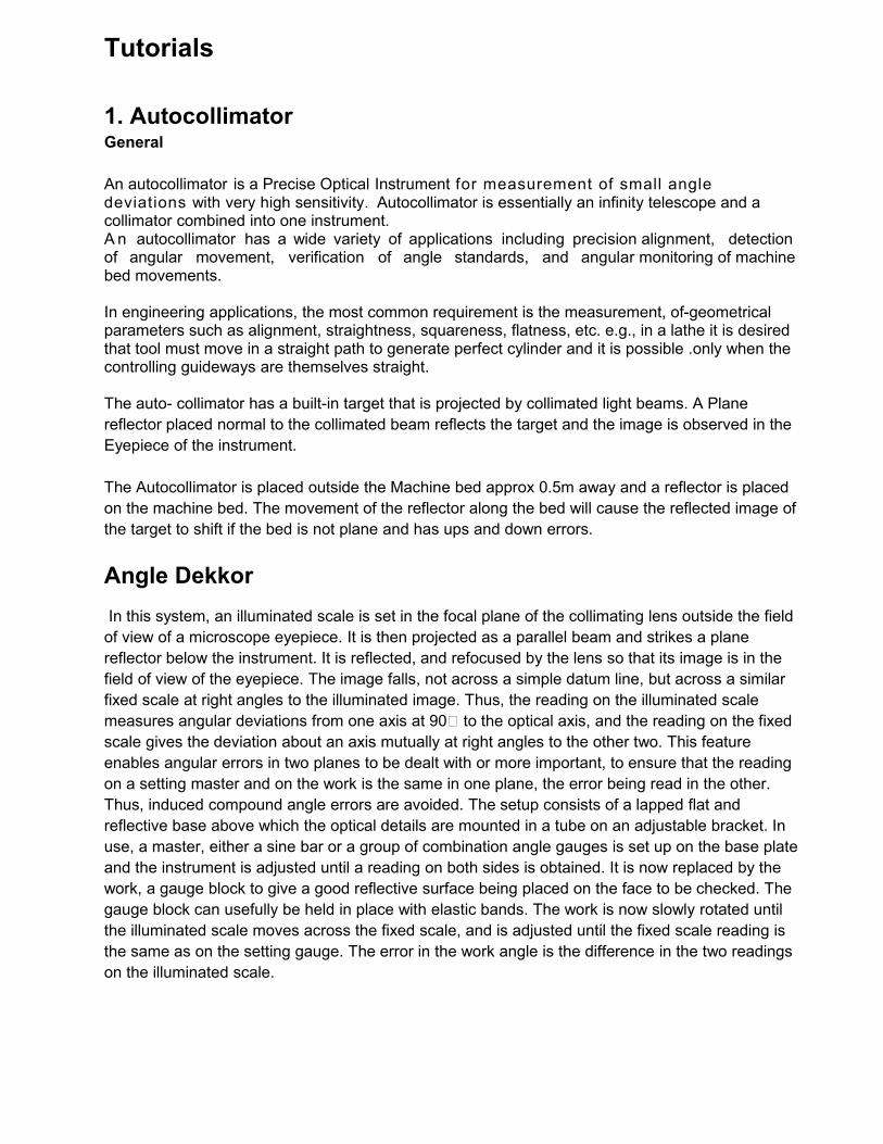
Surface Table Flatness Measurements
Additionally two reflectors may be required to keep the Autocollimator position the same for both x & Y straightness measurements. In place of reflector a Penta Prism could also be used.If only one additional reflector is used, then the Autocollimator position should be altered.
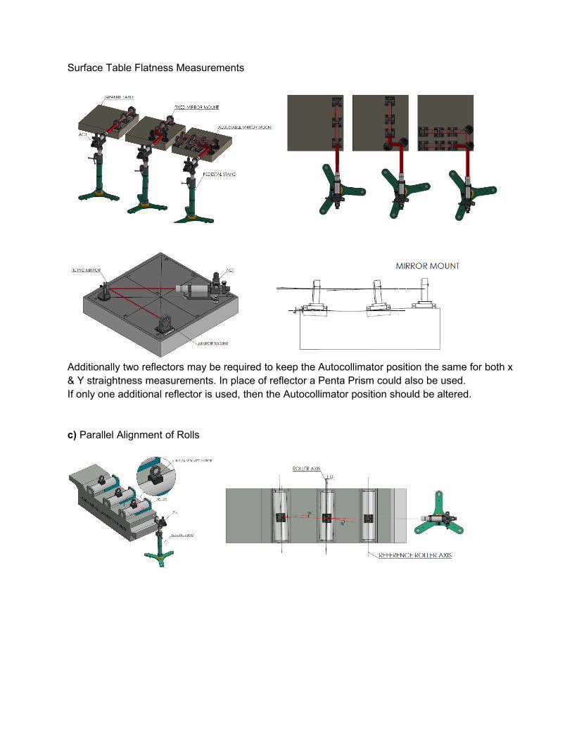
c) Parallel Alignment of Rolls

d) Squareness
For squareness measurement, the Autocollimator should be set in line with the Machine bed. The procedure is similar with straightness measurement. A reflector is placed on the bed and the Autocollimator is placed away from the machine bed and set as a reference. An accurate pentaprism is placed very close to the vertical column used to transfer the autocollimator beam to the second surface. The straightness of the second surface is measured. The data are then combined and corrected for the error of the pentaprism
e) Rotary Indexing
A reflecting polygon is put on rotary table or dividing head under test. One side of the polygon is squared to the optical axis of the autocollimator. The rotary table is set on zero. The rotary table with the polygon is rotated until next polygon side is square to autocollimator. The graduation of the table is compared withthe expected angle.
Sighting Aid
This accessory is used when Autocollimator is used for inspection of long size bed straightness measurements. The Reflector/Mirror need to be aligned perpendicular to the axis of Autocollimator. There could be difficulty in locating the reflector when using for long distance. Through sighting aid you would observe two images, one from the Autocollimator and the other after reflection from the Mirror. The Reflector is tilted until the two images coincide. Once this adjustment is made, the Autocollimator would receive the image after reflection from the Mirror.

Position of Reflector for straightness measurement.
If the reflector is not positioned properly, the reflector may not reflect the beam back to the Autocollimator. The Sketch shown below is self explanatory for the reflection positioning.

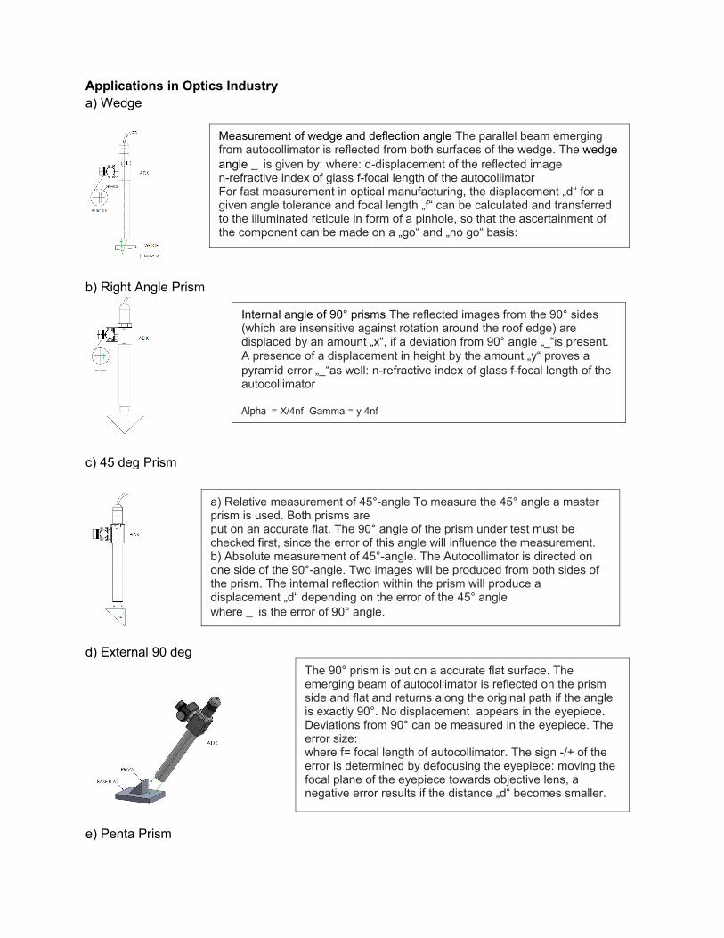
Applications in Optics Industrya) Wedge
b) Right Angle Prism
c) 45 deg Prism
d) External 90 deg
e) Penta Prism
Measurement of wedge and deflection angle The parallel beam emerging from autocollimator is reflected from both surfaces of the wedge. The wedge angle _ is given by: where: d-displacement of the reflected imagen-refractive index of glass f-focal length of the autocollimatorFor fast measurement in optical manufacturing, the displacement „d“ for a given angle tolerance and focal length „f“ can be calculated and transferred to the illuminated reticule in form of a pinhole, so that the ascertainment of the component can be made on a „go“ and „no go“ basis:
Internal angle of 90° prisms The reflected images from the 90° sides (which are insensitive against rotation around the roof edge) are displaced by an amount „x“, if a deviation from 90° angle „_“is present.A presence of a displacement in height by the amount „y“ proves a pyramid error „_“as well: n-refractive index of glass f-focal length of the autocollimator
Alpha = X/4nf Gamma = y 4nf
The 90° prism is put on a accurate flat surface. The emerging beam of autocollimator is reflected on the prism side and flat and returns along the original path if the angle is exactly 90°. No displacement appears in the eyepiece. Deviations from 90° can be measured in the eyepiece. The error size:where f= focal length of autocollimator. The sign -/+ of the error is determined by defocusing the eyepiece: moving the focal plane of the eyepiece towards objective lens, a negative error results if the distance „d“ becomes smaller.
a) Relative measurement of 45°-angle To measure the 45° angle a master prism is used. Both prisms areput on an accurate flat. The 90° angle of the prism under test must be checked first, since the error of this angle will influence the measurement. b) Absolute measurement of 45°-angle. The Autocollimator is directed on one side of the 90°-angle. Two images will be produced from both sides of the prism. The internal reflection within the prism will produce a displacement „d“ depending on the error of the 45° angle where _ is the error of 90° angle.

The autocollimator is mounted on an adjustable stand and can be tilted at any angle. A master prism is used to align the autocollimator to the mirror. The master prism is replaced by the prism under test and the angle difference is read off through the eyepiece. Example: Measurement of deviation angle through pentaprisms.