two stage gas snow thrower - the home depot stage gas snow thrower model db7103-24 and 26 warning!...
TRANSCRIPT

TWO STAGE GAS SNOW THROWERMODEL DB7103-24 and 26
WARNING! Read and follow all safety rules and instructions in this manual before attempting to operate thismachine. Failure to comply with these instructions may result in personal injury. Save these instructions. Thisunit is equipped with an internal combustion engine and may spark resulting in fire or explosion if used nearcombustible material or fluid. Only use when the engine's exhaust system is equipped with a spark arrestermeeting applicable local or state laws (if any). The spark arrester shall be maintained in effective workingorder by operator.
Questions, problems, missing parts? If you have questions or need technical support, call theAmerisun customer service department at 1-800-791-9458 or visit Amerisuninc.com or [email protected]. For engine related problems, questions and warranty service call the enginemanufacturer 1-877-274-2214.
1
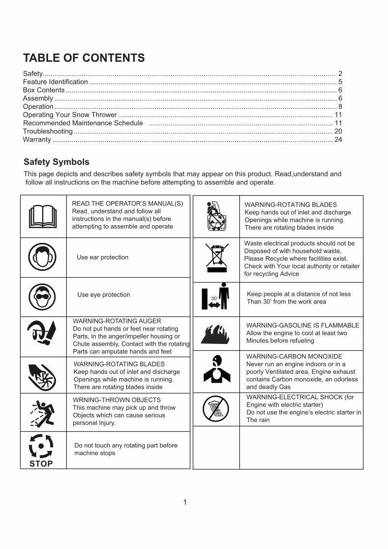
TABLE OF CONTENTSSafety....................................................................................................................................................... 2Feature Identification ................................................................................................................................ 5Box Contents ................................................................................................................... ......................... 6Assembly .................................................................................................................................................. 6Operation .................................................................................................................................................. 8Operating Your Snow Thrower ............................................................................................................... 11
............................................................................................... 11Troubleshooting...................................................................................................................................... 20Warranty ................................................................................................................................................. 24
Safety SymbolsThis page depicts and describes safety symbols that may appear on this product. Read,understand andfollow all instructions on the machine before attempting to assemble and operate.
Recommended Maintenance Schedule
READ THE OPERATOR’S MANUAL(S)Read, understand and follow all instructions in the manual(s) before attempting to assemble and operate
Use ear protection
Use eye protection
WARNING-ROTATING AUGERDo not put hands or feet near rotatingParts, in the anger/impeller housing orChute assembly, Contact with the rotatingParts can amputate hands and feet
WARNING-ROTATING BLADES Keep hands out of inlet and discharge Openings while machine is running.
There are rotating blades inside
WRNING-THROWN OBJECTSThis machine may pick up and throw
Objects which can cause serious personal Injury.
Do not touch any rotating part before machine stops
30’
WARNING-ROTATING BLADES Keep hands out of inlet and discharge Openings while machine is running. There are rotating blades inside
Waste electrical products should not be Disposed of with household waste, Please Recycle where facilities exist. Check with Your local authority or retailer for recycling Advice
Keep people at a distance of not lessThan 30’ from the work area
WARNING-GASOLINE IS FLAMMABLE Allow the engine to cool at least two Minutes before refueling
WARNING-CARBON MONOXIDE Never run an engine indoors or in a poorly Ventilated area, Engine exhaust contains Carbon monoxide, an odorless and deadly Gas WARNING-ELECTRICAL SHOCK (for Engine with electric starter) Do not use the engine’s electric starter in The rain

2
SAFETYThis symbol points out important safetyinstructions which, if not followed, couldendanger the personal safety and or
property of yourself and others. Read and followall instructions in this manual before attemptingto operate this machine. Failure to comply withthese instructions may result in personal injury.WARNING! This machine was built to beoperated according to the safe operationpractices in this manual. As with any type ofpower equipment, carelessness or error onthe part of the operator can result in seriousinjury. This machine is capable of amputatingfingers, hands, toes and feet and throwingforeign objects. Failure to observe thefollowing safety instructions could result inserious injury or death.It is your responsibility to restrict the use of thispower machine to persons who read, understandand follow the warnings and instructions in thismanual and on the machine.
SAVE THESE INSTRUCTIONS!TrainingRead, understand, and follow all instructions onthe machine and in the manual(s) beforeattempting to assemble and operate. Keep thismanual in a safe place for future and regularreference.
Be familiar with all controls and their properoperation. Know how to stop the machine anddisengage them quickly.Never allow children under 14 years of age tooperate this machine. Children 14 and over shouldread and understand the instructions and safeoperation practices in this manual and on themachine and be trained and supervised by an adult.Never allow adults to operate this machine withoutproper instruction.Thrown objects can cause serious personal injury.Plan your snow-throwing pattern to avoid dischargeof material toward roads, bystanders and the like.Keep bystanders, pets and children at least 75 feetfrom the machine while it is in operation. Stopmachine if anyone enters the area.Exercise caution to avoid slipping or falling,especially when operating in reverse.
PreparationThoroughly inspect the area where theequipment is to be used. Remove all doormats,newspapers, sleds, boards, wires ,branches andother foreign object, which could be tripped over orthrown by the auger /impeller.
Always wear safety glasses or eye shields duringoperation and while performing an adjustment orrepair to protect your eyes, thrown objects whichricochet can cause serious injury to the eyes.Do not operate without wearing adequate winterouter garments. Do not wear jewelry, long scarvesor other loose clothing, which could becomeentangled in moving parts, wear footwear which willimprove footing on slippery surfaces.Use a grounded three-wire extension cord andreceptacle for all machines with electric startengines.Adjust housing height to clear gravel orcrushed rock surfaces.Disengage all control levers before starting theengine.Never attempt to make any adjustments whileengine is running, except where specificallyrecommended in the operator's manual.Let engine and machine adjust to outdoortemperature before starting to clear snow.
Personal SafetyEngine exhaust, and certain vehicle components
contain or emit chemicals known to cause cancer,birth defects or other reproductive harm.Read, understand and follow all instructions on yourSnow Thrower and in this Operator's Manual beforeattempting to assemble and operate your machine.Keep this manual in a safe place for future andregular reference. If replacement parts are needed,refer to the manual.Stay alert, watch what you are doing and usecommon sense when operating your Snow Thrower.Do not use your Snow Thrower while you are tiredor under the influence of drugs, alcohol, medication.A moment of inattention while operating the SnowThrower may result in severe bodily injury.NEVER LEAVE YOUR RUNNING SNOWTHROWER UNATTENDED. Stop the engine.Do leave your Snow Thrower until it has come to acomplete stop.When stepping backwards, be cautious about anyobstacles beneath your feet or behind you avoidfalling.
3
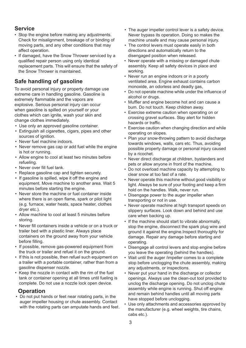
ServiceStop the engine before making any adjustments.Check for misalignment, breakage of or binding ofmoving parts, and any other conditions that mayaffect operation.If damaged, have the Snow Thrower serviced by aqualified repair person using only identicalreplacement parts. This will ensure that the safety ofthe Snow Thrower is maintained.
Safe handling of gasolineTo avoid personal injury or property damage useextreme care in handling gasoline. Gasoline isextremely flammable and the vapors areexplosive. Serious personal injury can occurwhen gasoline is spilled on yourself or yourclothes which can ignite, wash your skin andchange clothes immediately.
Use only an approved gasoline container.Extinguish all cigarettes, cigars, pipes and othersources of ignition.Never fuel machine indoors.Never remove gas cap or add fuel while the engineis hot or running.Allow engine to cool at least two minutes beforerefueling.Never over fill fuel tank.Replace gasoline cap and tighten securely.If gasoline is spilled, wipe it off the engine andequipment. Move machine to another area. Wait 5minutes before starting the engine.Never store the machine or fuel container insidewhere there is an open flame, spark or pilot light(e.g. furnace, water heats, space heater, clothesdryer etc.).Allow machine to cool at least 5 minutes beforestoring.Never fill containers inside a vehicle or on a truck ortrailer bed with a plastic liner. Always placecontainers on the ground away from your vehiclebefore filling.If possible, remove gas-powered equipment fromthe truck or trailer and refuel it on the ground.If this is not possible, then refuel such equipment ona trailer with a portable container, rather than from agasoline dispenser nozzle.Keep the nozzle in contact with the rim of the fueltank or container opening at all times until fueling iscomplete. Do not use a nozzle lock open device.
OperationDo not put hands or feet near rotating parts, in theauger impeller housing or chute assembly. Contactwith the rotating parts can amputate hands and feet.
The auger impeller control lever is a safety device.Never bypass its operation. Doing so makes themachine unsafe and may cause personal injury.The control levers must operate easily in bothdirections and automatically return to thedisengaged position when released.Never operate with a missing or damaged chuteassembly. Keep all safety devices in place andworking.Never run an engine indoors or in a poorlyventilated area. Engine exhaust contains carbonmonoxide, an odorless and deadly gas,Do not operate machine while under the influence ofalcohol or drugs.Muffler and engine become hot and can cause abum. Do not touch. Keep children away.Exercise extreme caution when operating on orcrossing gravel surfaces. Stay alert for hiddenhazards or traffic.Exercise caution when changing direction and whileoperating on slopes.Plan your snow-throwing pattern to avoid dischargetowards windows, walls, cars etc. Thus, avoidingpossible property damage or personal injury causedby a ricochet.Never direct discharge at children, bystanders andpets or allow anyone in front of the machine.Do not overload machine capacity by attempting toclear snow at too fast of a rate.Never operate this machine without good visibility orlight. Always be sure of your footing and keep a firmhold on the handles. Walk, never run.Disengage power to the auger impeller whentransporting or not in use.Never operate machine at high transport speeds onslippery surfaces. Look down and behind and usecare when backing up.If the machine should start to vibrate abnormally,stop the engine, disconnect the spark plug wire andground it against the engine.Inspect thoroughly fordamage. Repair any damage before starting andoperating.Disengage all control levers and stop engine beforeyou leave the operating (behind the handles).Wait until the auger /impeller comes to a completestop before unclogging the chute assembly, makingany adjustments, or inspections.Never put your hand in the discharge or collectoropenings. Always use the clean-out tool provided tounclog the discharge opening. Do not unclog chuteassembly while engine is running. Shut off engineand remain behind handles until all moving partshave stopped before unclogging.Use only attachments and accessories approved bythe manufacturer (e.g. wheel weights, tire chains,cabs etc.).
4
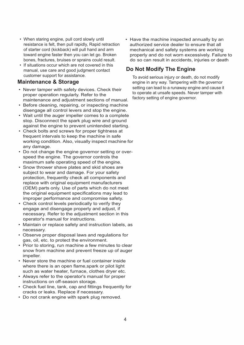
When staring engine, pull cord slowly untilresistance is felt, then pull rapidly, Rapid retractionof starter cord (kickback) will pull hand and armtoward engine faster then you can let go. Brokenbones, fractures, bruises or sprains could result.If situations occur which are not covered in thismanual, use care and good judgment contactcustomer support for assistance.
Maintenance & StorageNever tamper with safety devices. Check theirproper operation regularly. Refer to themaintenance and adjustment sections of manual.Before cleaning, repairing, or inspecting machinedisengage all control levers and stop the engine.Wait until the auger impeller comes to a completestop. Disconnect the spark plug wire and groundagainst the engine to prevent unintended starting.Check bolts and screws for proper tightness atfrequent intervals to keep the machine in safeworking condition. Also, visually inspect machine forany damage.Do not change the engine governor setting or over-speed the engine. The governor controls themaximum safe operating speed of the engine.Snow thrower shave plates and skid shoes aresubject to wear and damage. For your safetyprotection, frequently check all components andreplace with original equipment manufacturers(OEM) parts only. Use of parts which do not meetthe original equipment specifications may lead toimproper performance and compromise safety.Check control levels periodically to verify theyengage and disengage properly and adjust, ifnecessary. Refer to the adjustment section in thisoperator's manual for instructions.Maintain or replace safety and instruction labels, asnecessary.Observe proper disposal laws and regulations forgas, oil, etc. to protect the environment.Prior to storing, run machine a few minutes to clearsnow from machine and prevent freeze up of augerimpeller.Never store the machine or fuel container insidewhere there is an open flame,spark or pilot lightsuch as water heater, furnace, clothes dryer etc.Always refer to the operator's manual for properinstructions on off-season storage.Check fuel line, tank, cap and fittings frequently forcracks or leaks. Replace if necessary.Do not crank engine with spark plug removed.
Have the machine inspected annually by anauthorized service dealer to ensure that allmechanical and safety systems are workingproperly and do not worn excessively. Failure to do so can result in accidents, injuries or death.
Do Not Modify The EngineTo avoid serious injury or death, do not modifyengine in any way. Tampering with the governorsetting can lead to a runaway engine and cause itto operate at unsafe speeds. Never tamper withfactory setting of engine governor.

5
FEATURE IDENTIFICATIONTECHNICAL SPECIFICATIONS
Clearing Width: DB7103 24 and 26 inchesClearing Height: 21 inches
6 Forward and 2 Reverse SpeedsEngine Displacement: 208cc, 4 stroke
A - Drive Control Handle E - Engine I - Snow/Ice Clean Out ToolB - Speed Control Lever F - Skid Shoe J - Chute AssemblyC - Auger Control Handle G- Augers K - Chute Deflector Lever
rellepmI-HeldnaHnoitatoRetuhC-D
AC
K B
D
J
I
H
GF
E
For a complete parts breakdown go to www.amerisuninc.com
L
L - Light
6
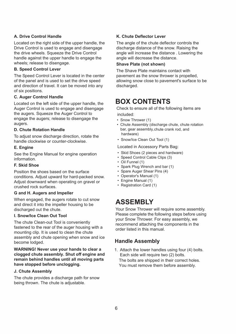
A. Drive Control HandleLocated on the right side of the upper handle, theDrive Control is used to engage and disengagethe drive wheels. Squeeze the Drive Controlhandle against the upper handle to engage thewheels; release to disengage.B. Speed Control LeverThe Speed Control Lever is located in the centerof the panel and is used to set the drive speedand direction of travel. It can be moved into anyof six positions.C. Auger Control HandleLocated on the left side of the upper handle, theAuger Control is used to engage and disengagethe augers. Squeeze the Auger Control toengage the augers; release to disengage theaugers.D. Chute Rotation HandleTo adjust snow discharge direction, rotate thehandle clockwise or counter-clockwise.E. EngineSee the Engine Manual for engine operationinformation.F. Skid ShoePosition the shoes based on the surfaceconditions. Adjust upward for hard-packed snow.Adjust downward when operating on gravel orcrushed rock surfaces.G and H. Augers and ImpellerWhen engaged, the augers rotate to cut snowand direct it into the impeller housing to bedischarged out the chute.I. Snow/Ice Clean Out ToolThe chute Clean-out Tool is convenientlyfastened to the rear of the auger housing with amounting clip. It is used to clean the chuteassembly and chute opening when snow and icebecome lodged.WARNING! Never use your hands to clear aclogged chute assembly. Shut off engine andremain behind handles until all moving partshave stopped before unclogging.J. Chute AssemblyThe chute provides a discharge path for snowbeing thrown. The chute is adjustable.
K. Chute Deflector LeverThe angle of the chute deflector controls thedischarge distance of the snow. Raising theangle will increase the distance . Lowering theangle will decrease the distance.Shave Plate (not shown)The Shave Plate maintains contact withpavement as the snow thrower is propelled,allowing snow close to pavement's surface to bedischarged.
BOX CONTENTSCheck to ensure all of the following items areincluded:
Snow Thrower (1)Chute Assembly (discharge chute, chute rotationbar, gear assembly,
Snow/Ice Clean Out Tool (1)
Located in Accessory Parts Bag:Skid Shoes (2 pieces and hardware)Speed Control Cable Clips (3)Oil Funnel (1)Spark Plug Wrench and bar (1)Spare Auger Shear Pins (4)Operator's Manual (1)Engine Manual (1)Registration Card (1)
ASSEMBLYYour Snow Thrower will require some assembly.Please complete the following steps before usingyour Snow Thrower. For easy assembly, werecommend attaching the components in theorder listed in this manual.
Handle Assembly1. Attach the lower handles using four (4) bolts.
Each side will require two (2) bolts.The bolts are shipped in their correct holes.You must remove them before assembly.
chute crank rod, and hardware)

7
2.
Attach the chute rotation bar to the mountbracket onto the chute housing using two hexscrews, washers and locknuts. Tightenfasteners securely.
3.
Slide the chute crank rod through the mountinghole
2. Attached the upper handle to the lower handleusing four (4) knobs, washers and bolts.
NOTICE: Do not bend or kink the control cables.The cables should be routed under the handleassembly and not wrapped around the handle orknobs. The cables must move freely and not bind.3. Secure the speed control cables to the handle
with provided clips.Note: Do not secure the auger or drive controlcables with the clips.
Chute Assembly1. Install the discharge chute onto the chute
flange on the housing. The chute only rests onthe flange.
on the left upper handle.
8
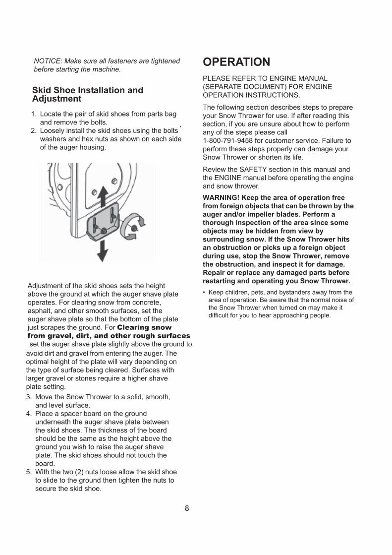
Skid Shoe Installation andAdjustment1. Locate the pair of skid shoes from parts bag
and remove the bolts.2. Loosely install the skid shoes using the bolts
,
washers and hex nuts as shown on each sideof the auger housing.
Adjustment of the skid shoes sets the heightabove the ground at which the auger shave plateoperates. For clearing snow from concrete,asphalt, and other smooth surfaces, set theauger shave plate so that the bottom of the platejust scrapes the ground. For Clearing snowfrom gravel, dirt, and other rough surfacesset the auger shave plate slightly above the ground to
avoid dirt and gravel from entering the auger. Theoptimal height of the plate will vary depending onthe type of surface being cleared. Surfaces withlarger gravel or stones require a higher shaveplate setting.3. Move the Snow Thrower to a solid, smooth,
and level surface.4. Place a spacer board on the ground
underneath the auger shave plate betweenthe skid shoes. The thickness of the boardshould be the same as the height above theground you wish to raise the auger shaveplate. The skid shoes should not touch theboard.
5. With the two (2) nuts loose allow the skid shoeto slide to the ground then tighten the nuts tosecure the skid shoe.
OPERATIONPLEASE REFER TO ENGINE MANUAL(SEPARATE DOCUMENT) FOR ENGINEOPERATION INSTRUCTIONS.
The following section describes steps to prepareyour Snow Thrower for use. If after reading thissection, if you are unsure about how to performany of the steps please call1-800-791-9458 for customer service. Failure toperform these steps properly can damage yourSnow Thrower or shorten its life.
Review the SAFETY section in this manual andthe ENGINE manual before operating the engineand snow thrower.WARNING! Keep the area of operation freefrom foreign objects that can be thrown by theauger and/or impeller blades. Perform athorough inspection of the area since someobjects may be hidden from view bysurrounding snow. If the Snow Thrower hitsan obstruction or picks up a foreign objectduring use, stop the Snow Thrower, removethe obstruction, and inspect it for damage.Repair or replace any damaged parts beforerestarting and operating you Snow Thrower.
Keep children, pets, and bystanders away from thearea of operation. Be aware that the normal noise ofthe Snow Thrower when turned on may make itdifficult for you to hear approaching people.
NOTICE: Make sure all fasteners are tightenedbefore starting the machine.

9
Start your clearing path by throwing snow in a backand forth motion. To clear in the opposite direction,stop your Snow Thrower and pivot it on its wheels toface the opposite direction. Make sure to overlap clearing paths.Determine the direction of the wind. If possible,move in the same direction as the wind so that thesnow is not thrown against the wind, back into yourface and on the just cleared path.
WARNING! DO NOT USE YOUR HANDS TOUNCLOG CHUTE. Stop the motor beforeremoving debris. Use the supplied clean outtool to unclog the chute. Do not walk in frontof your running Snow Thrower. Do not directdischarged snow towards bystanders.
Do not apply additional weight to be top of theengine since this may damage the engine.Some parts of your Snow Thrower may freezeunder extreme temperature conditions. Do notattempt to operate your Snow Thrower with frozenparts. If the parts freeze while your Snow Thrower isin use, stop your Snow Thrower and inspect it forfrozen parts. Thaw all parts before restarting andoperating your Snow Thrower. Never force parts orcontrols that have frozen. Never use an open flameof any sort to thaw frozen parts.WORKING ON PEBBLES, GRAVEL, OR UNPAVEDSURFACES. To avoid throwing loose surfacematerial along with the snow, push down on thehandle to raise the scraper at the base of the unitabove the pebbles or gravel.
Pre-Operation Inspection -IMPORTANT!!!Before using your Snow Thrower for the firsttime, check the following:
Have you read and followed all setup and operationprocedures for the engine as outlined in theENGINE manual?Has the engine been filled with oil to the properlevel?Are all snow thrower components properly attachedand assembled?Are there any broken or damaged parts?Are all fasteners tight?Are the auger, drive and speed controls cablesrouted properly so that are not kinked and controlsoperate smoothly?Are the auger, drive and speed controls cablesadjusted correctly?Are the tires inflated to the proper pressure?
NOTICE: If you are unsure about the assembly orcondition of any of your Snow Thrower parts,please call customer service department.
Auger and Drive Controls1. To engage the auger, press down on the
auger control handle (left side handle).
2. To engage the drive, press down on the drivecontrol handle (right side handle). Themachine should start moving in the directionand speed that the speed control lever is setto.
3. When finished clearing a snow path, releasethe auger control handle and the drive controlhandle.
Note: Release (disengage) the auger anddrive control handles before adjusting thedrive speed control lever. Never change thedrive speed while your snow thrower ismoving, it could damage the drivemechanism and void the warranty.

10
Drive Speed Control LeverMove the drive speed control lever to the desiredspeed. There are eight(8)settings:six (6) forwardspeeds and two (2) reverse speeds. 1 is theslowest forward speed and 6 is the fastestforward speed. R1 is the slowest reverse speedand R2 is the fastest reverse speed.
Note: There is no neutral drive setting sincethe drive control handle must be engaged formovement. Neutral is achieved when thedrive control handle is disengaged.
Chute Discharge DirectionAdjustmentWARNING - Never direct the snow dischargechute at the operator, bystanders, vehicles ornearby windows. Discharged snow and foreignobjects accidentally picked up by the SnowThrower can cause serious damage and severebodily injury. Always point the discharge chute inthe opposite direction from potential hazards.
The discharge chute can be adjusted 180º byrotating the chute rotation handle. Rotate thechute rotation handle clockwise to move thedischarge chute to the left; counterclockwise tomove the chute to the right.
Chute Discharge Angle AdjustmentWARNING! Always disengage the drive andauger control handles before makingadjustments. Make sure the augers arestopped and the machine is not moving.The angle of the chute deflector controls thedischarge distance of the snow. Raising theangle will increase the distance. Lowering theangle will decrease the distance.
The angle can be adjusted by moving the chutedeflector control lever. Move the lever to the leftto raise the throwing height and move the lever tothe right to lower the throwing height.

11
OPERATING YOUR SNOW THROWERStartingPlease refer to ENGINE manual (separatedocument) for engine operation instructions.
Clearing SnowStart the engine (see ENGINE manual) once yourSnow Thrower has been running outside forseveral minutes, it is now ready for use. Makesure the path in front of your Snow Thrower isfree from people, animals, objects, and all otherobstructions except for snow.
Adjust the chute outlet to the desired direction.Turn the chute rotation handle clockwise orcounter-clockwise until the desired position isreached.WARNING! Never direct the chute outlettoward people or animals. While snow mayseem harmless, it can contain rocks or otherdebris that can cause serious injury whenprojected through the chute.1. Engage/depress the auger control handle to
start the augers and impeller turning.2. Set the desired direction and speed using the
speed control lever.3. Engage/depress the drive control handle and
direct the snow thrower into the snow to becleared.
NOTICE: Do not change speed positions whilethe drive is engaged. Disengage the drive controlhandle BEFORE changing speeds or directions.
If the snow is deeper than the height of the auger,remove it in several steps taking narrowerswaths. Make several passes with the augeroverlapping the cleared areas and reduceforward speed.
For the best clearing efficiency, clear snowbefore it melts, refreezes and hardens. Hardpacked and wet snow can be very difficult toclear.
Clearing wet heavy snow can be a challenge,depending on ambient temperature, humiditylevels, and overall climate conditions includingactual snow conditions, there may be no 100%solution as snow may be too wet or compacted to
move or throw. Wet snow will tend to clog andstick more to the augers and chute. Keep theauger engaged as much as possible whenclearing wet snow to help prevent clogging.WARNING! If snow is filled with foreignmaterial, damage to the snow thrower mayresult. Avoid snow with foreign materials.
StoppingWhen finished using your Snow Thrower,perform the following steps to shut it down.1. Engage the auger and impeller for 30 seconds
to clear any remaining snow inside your SnowThrower.
2. Stop the auger by releasing the left controlhandle.
3. Set the engine switch to the OFF position.See ENGINE manual for stopping procedures.
4. Remove snow from all Snow Throwersurfaces including the auger housing andchute areas.
Clearing RestrictionsIf the snow discharge chute or auger housingbecomes clogged STOP the engine, and makesure that all rotating parts have come to acomplete stop. Remove the spark plug cap fromthe spark plug.
Use the supplied snow clean out tool to clear theobstruction. After unclogging, wipe the tool clean,and place it in the holder on top of the augerhousing.
MAINTENANCEWARNING! Never perform maintenance whileyour Snow Thrower is running. Turn OFF theengine before performing any maintenancetasks on your Snow Thrower.Proper maintenance of your Snow Thrower willhelp prolong its life. Please perform the followingmaintenance procedures as required.
Please read the ENGINE manual for enginemaintenance procedures.
Do not attempt to repair your Snow Throwerunless you have the proper tools and instructionsfor disassembly and repair.

12
Check the bolts at frequent intervals for propertightness to ensure that the equipment is in safeworking condition.
After each snow removal session, run the SnowThrower for a few minutes to prevent thecollector/impeller from freezing. Stop the engine,wait for all revolving parts to stop completely, andwipe residual ice and snow off the unit. Rotatethe chute rotation handle several times to removeany excess snow.
Maintenance ProceduresTire InflationBefore each use of your Snow Thrower, checkthe tire pressure. The pressure in each tireshould be in the range of 20-24 psi for the bestperformance. The pressure can be checkedusing an ordinary tire pressure gauge. Fill thetires using an small or pressure regulated air compressor.
WARNING! DO NOT OVER-INFLATE THE TIRES. Over-inflating could cause a tire toburst and cause severe bodily injury.Shave Plate ReplacementRemove both skid shoes and hardware includingcarriage bolts and nuts which attach shave plateto snow thrower housing. Reassemble newshave plate, making sure heads of the carriagebolts are to the inside of the housing.
Auger or Impeller JamsWARNING! The auger and impeller rotate atfast speeds which can cause harm or evenamputation to a person's body parts. Even ifyou do not see the auger or impeller rotating,it may start at any time if the engine is running.The chute clean-out tool is fastened to the top ofthe auger housing with a mounting clip and acable tie at the factory. Cut the cable tie beforeoperating the snow thrower.1. Always turn OFF the engine before attempting
to clear any clogs or jams.2. Keep hands and feet away from rotating parts
while the engine is running.3. Do not wear loose fitting clothing that can
become entangled in rotating parts.4. Wait until the auger and impeller have come to
a full stop.5. Clear any visible jams using the clean out tool
attached to your machine.WARNING! DO NOT try to clear jams with yourhands or feet.
Recommended Maintenance ScheduleMaintence Service Interval
Procedure
After 1st 2 hours
Inspect traction cable and adjust if necessaryInspect auger/impeller and adjust if necessaryChange oil
Before each use Check oil level and add oil as necessary
Every 50 hoursChange oil,change oilevery 25 operating hourswhen operating under heavy load
Every 100 hours Replace the spark plug
Yearly
Before storage
Check air pressure of tires20-24 psiReplace auger or drive belt as necessary
Check skid shoes and adjust as necessaryInspect drive cable and adjust replace as
cable
necessaryInspect the auger/impeller cable and adjust orreplace as necessary
Spray WD-40 to moving cables parts

13
Auger Shear Pin Replacement Shear pins are used to attach the auger shaft tothe auger blades. A clog or jam in the augersmay cause one or multiple shear pins to break.The shear pins are a safety mechanism anddesigned to break under high load or impact toprotect the auger drive system from damage.Replacement shear pins and nylon locknuts areprovided with your snow thrower. For additionalreplacement shear pins, please call the customerservice department.
1. Turn off the engine and wait for all movingparts to come to a complete stop.
Remove any remnants of the broken shear pin. Itmay be necessary to unscrew the nut from thebroken shear pin and drive out the broken pin.2. Insert a new shear pin through the hole in the
auger shaft and tighten using the shear pinhex nut. Do not over-tighten the hex nut.
NOTICE: Never replace the shear pins withstandard pins or fasteners. Damage may occur tothe snow blower and drive systems.
Drive Control Cable TensionAdjustmentWARNING! Entanglement Hazard - Beforeperforming any adjustment procedures, makesure the engine is off and remove the sparkplug wire from the spark plug to ensure theengine cannot accidently start. Never adjustcable tension with the engine running.The drive control cable is located on the rightside (when standing behind the snow blower)and is made up of an upper and lower cableconnected by an adjustment plate. Theadjustment plate is located in-line with the cablebelow the control handle and is covered by ablack plastic slip cover. The adjustment plate isused to adjust the drive control cable drive wheelfriction tension.1. Stop the engine.2. Disconnect the upper cable from the drive
control handle.
3. Slide up the slip cover to access theadjustment plate.
1 – Upper Drive Control Cable (Always in upper centerhole)
2 – Adjustment Plate3 – Lower Drive Control Cable4 – Slip Cover5 – Adjustment Plate Lower Cable Opening
Checking auger gear box oil levelService yearly-check the auger gear box oil and add oil if necessary
1. Clean area around pipe plug2. Remove pipe plug from top of gear box3. Check oil level. The oil should be to a point of over flowing at the opening 4. Add GL-5 or GL-6, SAE 85-95EP gear oil lubricant to the point of overflowing
NOTE: Do not use synthetic oil 5. Install the pipe plug in the gear box.6. Every 3 Years, replace lubricant. Drain plug is on the bottom of the housing. Drain, replace plug, and add lubricant.

14
Note: The upper cable end must be in theupper single center hole of the adjustmentplate. Do not change the position of the uppercable.
5. Connect the upper cable to the control handle.6. Start the engine and engage the drive control
handle to test the operation of the driveengagement.
Note: With the drive control handle at the fullreleased position, the cable should be barelytight. Some slack in the cable may be required to ensure the drive control is not engaging the drive friction wheel. Thereshould be no drive movement with the drivecontrol handle released. If the drive isengaged when the drive control handle isreleased, loosen the cable tension byreadjusting the cable as necessary. Do notover tension the cable.
Drive Speed Control CableAdjustmentWARNING! Entanglement Hazard - Usecaution when performing the speed controlcable adjustment.The speed control lever is connected to twocables that work in tandem to control machinespeed and direction. As the speed control lever ismoved from forward to reverse gears (right toleft) one cable is pulled and one is pushed.
Depending on if the cable setting is biasedtowards forward or reverse, adjustment of thecables will vary.
To adjust the cables one cable should be movedup and the other down equally in their respectivebrackets until there is a positive direction changewhen the lever is shifted between F1 and R1.The middle position between these two settingsis neutral (there is no actual neutral "notched"position on the control panel)
1. With the engine running engage the drivecontrol handle and move the speed controllever between F1 and R1 to determine whichway the cables need to be adjusted. Releasethe drive control handle when shifting betweengears.
2. Loosen the jam nuts on each cable (only oneor two threads) and move each cable up anddown as required until a positive directionchange is achieved when the lever is shiftedbetween F1 and R1. This may take multipleattempts to find the exact setting.
3. Tighten the cable jam nuts once the propersetting has been achieved.
4. Adjustment is made by changing the positionof the lower cable in the adjustment plateholes (1 to 9). Only move the lower cablediagonally one hole at a time from its originalposition.
4. Lubricate with WD-40 for ease of movement.

15
Auger Belt Tension AdjustmentWARNING! Entanglement Hazard - Beforeperforming any adjustment procedures, makesure the engine is off and remove the sparkplug wire from the spark plug to ensure theengine cannot accidently start. Never adjustbelt tension with the engine running.
Note: During operation the augers turn at a slower speed than the impeller, this is normal.The augers are used to chop and cut thesnow and direct it into the impeller which isrotating at a high speed to throw the snow upand out of the chute.
Over time, the auger cable tension may loosenand or the auger belt may stretch. The augercable will require periodic adjustment tocompensate for these changes. Ideally, the cableshould just be barely tight when the auger handleis in the released (disengaged) position.
Note: The proper operating tension for atypical drive is - the lowest tension atwhich the belt will not slip under a loadedcondition.
1 – Drive Control Engagement Handle2 – Drive Speed Control Lever3 – Auger Control Engagement Handle4 – Chute Rotation Crank Handle5 – Drive Speed Cables6 – Auger Control Cable7 – Drive Control Cable8 – Chute Deflector Control Handle
The auger cable is located on the left side (whenstanding behind the snow blower) and is madeup of an upper and lower cable connected by anadjustment plate. The adjustment plate is locatedin-line with the cable below the control handleand is covered by a black plastic slip cover. Theadjustment plate is used to adjust auger belttension.
1 – Upper Auger Cable (Always in upper center hole)2 – Adjustment Plate3 – Lower Auger Cable4 – Cable Pulley5 – Adjustment Plate Lower Cable Opening6 – Slip Cover
1. Stop the engine.2. Disconnect the upper cable from the auger
control handle.
3. Slide up the slip cover to access theadjustment plate.
1 28
3
5 46
7
auger

16
4. Adjustment is made by changing the positionof the lower cable in the adjustment plateholes (1 to 9). Only move the lower cablediagonally one hole at a time from its originalposition.
Note: The upper cable end must be in theupper single center hole of the adjustmentplate. Do not change the position of the uppercable.
5. Connect the upper cable to the control handle.6. Start the engine and engage the auger to test
the operation of the auger.Note: With the auger control handle at the fullreleased position, the cable should be barelytight. Some slack in the cable may be required to ensure the auger pulley tensionpulley is not engaging the belt. There shouldbe no auger movement with the auger handlereleased. If the auger is turning when theauger handle is released, loosen the belttension by readjusting the cable asnecessary. Do not over tension the cable.
Auger Belt Removal WARNING! Entanglement Hazard - Beforeperforming any service procedures, makesure the engine is off and remove the sparkplug wire from the spark plug to ensure theengine cannot accidently start.
Note: Record component position beforedisassembly, to assist in reassembly.
1. Disconnect the upper cable from the augercontrol handle.
2. Remove 2 hex head screws and remove beltcover.
3. Loosen the belt guide pin hex head screw(installed on engine crankcase) and rotate thepin away from the pulley.
4. Left Side - Loosen the hex nuts attaching theauger housing to the main frame.
17
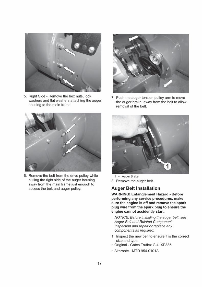
5. Right Side - Remove the hex nuts, lockwashers and flat washers attaching the augerhousing to the main frame.
6. Remove the belt from the drive pulley whilepulling the right side of the auger housingaway from the main frame just enough toaccess the belt and auger pulley.
7. Push the auger tension pulley arm to movethe auger brake, away from the belt to allowremoval of the belt.
1 – Auger Brake8. Remove the auger belt.
Auger Belt InstallationWARNING! Entanglement Hazard - Beforeperforming any service procedures, makesure the engine is off and remove the sparkplug wire from the spark plug to ensure theengine cannot accidently start.
NOTICE: Before installing the auger belt, seeAuger Belt and Related ComponentInspection and repair or replace anycomponents as required.
1. Inspect the new belt to ensure it is the correctsize and type.
Original - Gates Truflex G 4LXP885Alternate - MTD 954-0101A
18
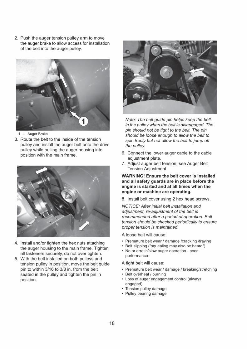
2. Push the auger tension pulley arm to movethe auger brake to allow access for installationof the belt into the auger pulley.
1 – Auger Brake3. Route the belt to the inside of the tension
pulley and install the auger belt onto the drivepulley while pulling the auger housing intoposition with the main frame.
4. Install and/or tighten the hex nuts attachingthe auger housing to the main frame. Tightenall fasteners securely, do not over tighten.
5. With the belt installed on both pulleys andtension pulley in position, move the belt guidepin to within 3/16 to 3/8 in. from the beltseated in the pulley and tighten the pin inposition.
Note: The belt guide pin helps keep the beltin the pulley when the belt is disengaged. Thepin should not be tight to the belt. The pinshould be loose enough to allow the belt tospin freely but not allow the belt to jump offthe pulley.
6. Connect the lower auger cable to the cableadjustment plate.
7. Adjust auger belt tension; see Auger BeltTension Adjustment.
WARNING! Ensure the belt cover is installedand all safety guards are in place before theengine is started and at all times when theengine or machine are operating.8. Install belt cover using 2 hex head screws.NOTICE: After initial belt installation andadjustment, re-adjustment of the belt isrecommended after a period of operation. Belttension should be checked periodically to ensureproper tension is maintained.
A loose belt will cause:Premature belt wear / damage /cracking /frayingBelt slipping ("squealing may also be heard")No or erratic/slow auger operation - poorperformance
A tight belt will cause:Premature belt wear / damage / breaking/stretchingBelt overheat / burningLoss of auger engagement control (alwaysengaged)Tension pulley damagePulley bearing damage

19
Auger Belt and Related ComponentInspectionWhen replacing your snow blower auger belt it isimportant to determine the cause of the failure (ifapplicable) and take corrective action to avoidrepeated failure.
Inspect the belt:Correct size and typeFraying or peeling apartMissing piecesCracks and tearsBurningUneven wear patternsGeneral damageForeign material on belt, oil, grease, dirt etc.
Inspect the auger pulleys:Broken sheave or hubLoose or missing mounting boltsBent or "out-of-round" condition (pulley not spin trueon shaft)Misaligned pulleys
1 – Drive Pulley2 – Tension Pulley3 – Auger PulleyForeign material on pulleys, oil, grease, dirt, etc.Misaligned tension pulleyTension pulley loose or damagedTension pulley and arm assembly operationDoes the tension arm move freely both engage anddisengage directions without binding?Misaligned tension pulley, the pulley should moveparallel to the belt centered to the beltCheck return spring operation and tension
Inspect the auger engagement handle and cable:Cable and connection damage
Free movement (from engage to disengagedpositions)Binding or improperly routed cableCable pulley(s) damage, misalignment and bindingCable adjustment plate damaged or improperinstallationHandle damaged or binding at pivot
StorageWARNING! Never store your Snow Throwerfor extended periods of time with fuel in thetank. Fuel stabilizer can be added to the fuel toextend its shelf life for storage.Store the unit, in a locked, dry place out of thereach of children to prevent unauthorized use ordamage. Cover loosely with a tarp for addedprotection.
Cleaning1. To clean your Snow Thrower, use a damp
cloth and mild detergent on the surfaces only.Never get soap or water inside the workingmechanisms of your Snow Thrower.
Note: Do not clean with water. Water willfreeze due to low temperature and damagethe machine.
2. Clean the Snow Thrower of snow and icebuildup before storing or transporting. Be sureto secure the unit while transporting.
3. Inspect the Snow Thrower carefully for worn,loose, or damaged parts. Check connectionsand screws and tighten if necessary.
1. Run the unit until the engine runs out of fuel.2. Remove the ignition key.3. Clean the unit thoroughly4. Touch up chipped paint5. Tighten all loose bolts, screws and locknuts. Repair or replace any damaged parts .6. Remove spark plug, put 1 teaspoon of motor oil in its hole.7. Check the auger gear box oil and add oil if necessary8. Cover unit and store it in a clean, dry place out of the reach of children.
Removing from StoragePerform the annual maintenance procedures according to the recommended maintenance schedule.

Problem Possible Causes Remedy
1 Engine ignition switch inOFF position 1 Position engine ignition switch to ON
2 Spark plug wiredisconnected 2 Connect wire to spark plug
3 Faulty spark plug 3 Clean, adjust gap, or replace sparkplug, see Engine Operator's manual
4 Engine flooded with fuel 4 Discontinue choke or primer use, cleanor replace spark plug
5 Safety key not inserted inengine ignition 5 Insert key fully into the switch
6 Choke not in STARTposition 6
Move choke to START position, afterengine starts slowly move to RUNposition as engine speed andoperation stabilizes at the set rpm. Ifengine still does not start, move to halfchoke and crank engine.
7 Engine not primed withfuel 7 Prime engine, see Engine Operator's
manual8 Fuel tank empty 8 Fill tank with clean, fresh gasoline
9 Water in fuel 9 Empty fuel tank & carburetor, refill withfresh, clean gasoline
10 Gas is old or hasseparated 10
Use clean 87 octane or higher use fuelstabilizer to the fuel all season. Do notuse E85 or E15. Do not add oil to thegas. Empty gas at end of season.
11 The fuel vent cap isblocked 11 Remove vent restriction, cut small
notch in gasket to allow air in.12 The Engine oil is too high 12 Drain oil and put in 16 ounces of oil.
13 Internal engine problem 13 See Engine Operator's manual,contact service center or engine
Engine recoilstarter will not pullout/hard to pull
1Frozen recoil starter orengine too cold to turnover
1 Move snow blower to warm space andallow it to warm up.
1Extension cord is notproperly attached toelectric starter terminal
1 Re-insert extension cord into electricstarter terminal.
2 No power from powersupply, tripped breaker 2 Check power supply extension cord is
attached to.
3Extension cord wire gaugeis too small or cord is toolong
3Use proper rated and length extensioncord no longer than 150 feet, 16 gaugeextension cord.
TROUBLESHOOTING
WARNING-Before attempting to make any inspections, repairs or adjustments, stop theengine, wait for all moving parts to stop moving and carefully disconnect the engine sparkplug wire. If tipping or turning the snow blower is required for any inspection or repair, firstwait until the engine is cool to the touch and then drain the engine of all fuel and oil intosuitable containers and store or dispose of in a proper manner.
Engine Fails toStart(Engine cranksover)
Engine electricstarter will notcrank engine
Engine Systems - Note: For all engine problems, see the Engine Operator's manual foradditional troubleshooting information and engine manufacturer contact information.
20

1 Cooling air flowrestricted to engine 1 Remove air flow restrictions from engine
2 Low oil level 2
Check oil level on dipstick. If oil is notvisible on dipstick, check oil level usingLOWER fill plug BEFORE adding oil. Oilshould be visible and to the top 2threads of LOWER fill plug(not thedipstick tube). Do not over fill with oil,see Engine Operator's manual for moreinformation. Note: Only use 5W-30,Engine oil capacity - 16 oz. The use ofautomotive synthetic oil is acceptable.
1 CHOKE in ON orpartial ON position 1 Move CHOKE lever to RUN
2 Water in fuel 2 Empty fuel tank & carburetor, refill withfresh, clean gasoline
3 Fuel incorrect, old orstale 3
Empty and clean fuel tank & carburetor,refill with fresh, clean gasoline. (Note:Fuel may become stale after 30 days insome cases) use gas stabilizer.
4 Blocked or clogged fuelsystem or line 4 Clean fuel system or line
5 Carburetor is in need ofcleaning 5 Clean fuel system and carburetor
6 Spark plug wire loose 6 Connect and tighten spark plug wire
7 Faulty spark plug 7 Clean, adjust gap, or replace spark plug,see Engine Operator's manual
8 Gas cap vent holeplugged 8
Remove ice and snow from gas cap,check to make sure gasket not coveringvent hole
9 Engine oil over filled 9Drain oil to proper level. Oil should notbe above the top 2 threads of LOWERfill plug.
10 Engine oil level low orempty 10
Check oil level on dipstick. If oil is notvisible on dipstick, check oil level usingLOWER fill plug BEFORE adding oil. Oilshould be visible and to the top 2threads of LOWER fill plug(not thedipstick tube). Do not over fill with oil,see Engine Operator's manual for moreinformation. Note: Only use 5W-30, 4-stroke automotive detergent oil. Engineoil capacity - 16 oz. The use ofautomotive synthetic oil is acceptable.
1 Engine oil over filled 1Drain oil to proper level. Oil should notbe above the top 2 threads of LOWERfill plug.
2 Internal engineproblem 2 See Engine Operator's manual, contact
service center or engine manufacturer.
EngineOverheats
Engine runserratic, stalls orseems low onpower
Engine smokesexcessively
21

1 Drive control cable loose,broken or binding 1 Repair or adjust drive control cable adjust tension.
See Auger and Drive Cable Adjustment.
2 Drive belt loose or damaged 2Check drive belt tension pulley for damage orincorrect tension, repair as necessary. Replacedrive belt.
3 Friction drive wheel is worn ordamaged 3 Replace friction drive wheel
4 Friction drive wheel wet orslipping 4 Allow snow blower to dry and or warm up or
adjust drive tension as necessary.
5 Wheel locked, won't move 5
Release drive control handle then pull machinebackward to try and unlock axle. If axle will notunlock, check to ensure drive friction plate is notengaged to drive friction wheel, also check axledrive gear, axle and bushings for damage orbinding.
6 Wheel to axle pins broken ormissing 6 Replace pins attaching wheels to axle
1Speed control lever loose ordamaged, not moving speedcontrol cables.
1
Check speed control lever and cables for damageor loose or missing parts. Repair or replace partsas needed, ensure pivot stud spring tension iscorrect, adjust pivot nut spring tension as needed.
2 Speed control cables loose,damaged or binding 2 Repair, adjust or replace as necessary
3Drive speed lower controllever or friction wheeldamaged or mechanically
3Inspect speed control lever and mechanicalconnection to friction drive wheel and slide shaftfor damage or binding.
Drive speedcontrol allowsonly onedirection forwardor reverse
1Speed control cablesmisajusted, loose, damaged orbinding
1
Check speed control lever and cables for damageor loose or missing parts. Repair or replace partsas needed. Adjust drive speed control cables, seeDrive Speed Control Cables Adjustment.
1 Drive control cable binding,won't release 1 Repair, replace cable as necessary
2 Friction drive wheel returnspring broken or missing 2 Replace spring, adjust cables as necessary
1 Chute assembly clogged 1 Clean chute and inside of auger housing withclean-out tool, spray lubricant in chute
2 Auger shear bolts broken 2 Replace shear bolts. Check each auger bladeshear bolt.
3Foreign object in auger orimpeller causing auger to stopwithout shearing pins
3 Remove object from auger or impeller areas
4 Auger belt loose, slipping wornor damaged 4 Replace auger belt or adjust auger control cable
tension, see Auger and Drive Cable Adjustment.
5 Auger belt tention cable loose,damaged or binding 5 Repair, adjust or replace as necessary
6 Auger blade(s) damaged orbent 6 Replace auger blade(s)
7Auger gear box mechanicaldamage, auger drive systemnot rotating freely, binding
7Check bearings, bushings and all system parts fordamage or mechanical binding. Repair or replaceas necessary using proper lubrication.
8 Impeller damaged 8 Replace impeller
Drive System
Auger Sytem
No forward orreverse drivemovement whendrive handleengaged
Drive speedcontrol stuck ingear or won'tchange gears
Drive engagedwhen drivecontrol handlereleased
Auger notrotating whenauger controlhandle engagedor not blowingsnow or poorsnow blowingperformance
22

9Impeller not connected toimpeller shaft, impeller or shaftdamaged or roll pins broken
9 Replace roll pins or impeller as necessary
10 Inadequate amount of snow 10Ingest an adequate amount of snow toallow snow to compact enough to be movedthrough augers and into impeller.
11 Snow too heavy or wet or hasother material in it 11
Depending on temperature, humidity levels,and overall climate conditions includingactual snow conditions there may be nosolutions as snow may be too wet orcompacted to move or throw. If snow isfilled with foreign material, damage to thesnow thrower may result. Avoid snow withforeign material.
12 Forward speed too fast whileblowing snow overload 12 Shift machine into lower gear
13 Engine not running at ratedspeed under load 13
Have engine inspected and RPM testedunder load to ensure engine is operating atthe recommended RPM. Check for machinemechnical binding causing engine to not runat rated RPM.
14 You are trying to remove toomuch snow per swath 14 Reduct the amount of snow removed per
swath
1 Auger tension pulley arm returnspring broken or missing 1 Replace tension arm return spring
2 Auger tension pulley arm stuckor binding 2 Repair or replace tension arm as necessary
3 Auger tension pulley arm orpulley misaligned or damaged 3 Repair, replace or align tension arm and or
pulley as necessary
4 Foreign material on pulleys andbelt, oil, grease, dirt, etc. 4 Clean belt and pulleys as necessary,
replace belt if necessary
5 Auger pulleys misaligned, loose,damaged or bent 5 Replace or align pulleys as necessary
6 Incorrect auger belt tension 6 Replace with correct size and type belt
7 Incorrect auger belt tension 7 Adjust auger cable tension, see Auger andDrive Cable Adjustment
8 Auger belt guide pin notadjusted 8
Adjust belt guide pin to within 1/8 to 3 in.from pulley (Guide pin keeps belt in pulleywhen disengaged)
1 Auger cable tension too tight ,belt too 1 Adjust auger cable tension, see Auger and
Drive Cable Adjustment
2 Auger tension pulley arm returnspring broken or missing 2 Replace tension arm return spring
ExcessiveVibration 1
Loose or damaged parts augerblades bent or impeller damagedor binding
1
Stop engine immediately and disconnectspark plug wire. Check and tighten all boltsand nuts. Inspect auger and impeller fordamage or foreign objects restrictionrotation. If vibration continues, stopoperation and contact service center or callAmerisun customer service for assistance.
Auger beltbroken, orrepeatedfailure
Augerrotating whenauger controlhandle
23

TWO YEAR WARRANTYAmerisun Inc. and LCT Engine Corporation jointly warrant this product for two years against defects in material or workmanship when used for normal residential purposes. The manufacturer will, at its option, repair or replace, for the original purchaser, any part or parts which have been found to be defective in material and workmanship.Residential use means use of the product on the same lot as your home.
If you have questions or problems, or before returning this product, call toll-free 1-800-791-9458 or email [email protected]
This warranty covers product defects only. Neither Amerisun nor LCT Engine Corporation is liable for indirect, incidental, or consequential damages in connection with the use of PowerSmart Products covered by this warranty, including any cost or expense of providing substitute equipment or service during reasonable periods of mal-function or non-use pending completion of repairs under this warranty. Transportation to and from the services center is the responsibility of the consumer. Some states do not allow exclusions of incidental or consequential damages, so the above exclusions may not apply to you. This warranty gives you specific legal rights, and you may also have other rights which vary from state to state.
DISCLAIMERThe information contained within this manual is the latest information as of the publication date. All contentand images are subject to change without notice. This manual is intended as a guide. This manual is in-tended as a guide. For the latest information and procedures visit amerisuninc.com.
24
C 2014 Amerisun Inc., Buffalo Grove, IL