type fks-eu - startseite | trox gmbh · type fks-eu compact dimensions, ... manual construction...
TRANSCRIPT

Type FKS-EU
COMPACT DIMENSIONS, IDEAL FOR RESTRICTED SPACES
Small rectangular fire damper for the isolation of duct penetrations between fire compartments, available in many sizes
Nominal sizes 200 × 100 to 800 × 200 mmLow differential pressure and sound power levelOptional stainless steel casing or powder-coated casing for increased corrosion protectionCan also be used as an air transfer damper or air transfer unitIntegration into the central BMS with TROXNETCOMUniversal installation options
Optional equipment and accessories
Electric actuator 24 V/230 VRelease temperature 72/95 °CDuct smoke detectors
Homepage > Products > Fire and Smoke Protection > Fire dampers > Type FKS-EU

Application
Fire dampers of Type FKS-EU, with CE marking and declaration of performance, forthe isolation of duct penetrations between fire compartments in the event of a fireTo prevent the propagation of fire and smoke through ductwork to adjacentdesignated fire compartments
Special characteristics
Declaration of performance according to Construction Products RegulationClassification to EN 13501-3, up to EI 120 (v , h , i ↔ o) SBuilding inspectorate licence Z-56.4212-991 for fire resistance propertiesComplies with the requirements of EN 15650Tested to EN 1366-2 for fire resistance propertiesHygiene complies with VDI 6022 part 1 (07/2011), VDI 3803 (10/2002), DIN 1946part 4 (12/2008), and EN 13779 (09/2007)Corrosion protection according to EN 15650 in connection with EN 60068-2-52Closed blade air leakage to EN 1751, class 2Casing air leakage to EN 1751, class CLow differential pressure and sound power levelAny airflow directionIntegration into the central BMS with TROXNETCOM
Classification
Class of performance to EN 13501-3, up to EI 120 (v , h , i ↔ o) S
Nominal sizes
B × H: 200 × 100 – 800 × 200 mm (width in increments of 50 mm)L: 300 mm
e o
e o
Variants
With fusible linkWith spring return actuatorWith cover grilles both ends as air transfer unit with general building inspectoratelicence: Z-19.18-2127With spring return actuator and duct smoke detectorWith spring return actuator, duct smoke detector and cover grilles on both ends foruse as an air transfer opening, with general building inspectorate licence Z-6.50-2231
Parts and characteristics
Easy dry mortarless installation into solid walls and ceiling slabs, lightweightpartition walls, fire walls and shaft walls using an installation blockRelease temperature 72 °C or 95 °C (for use in warm air ventilation systems)
Attachments

Limit switch for damper blade position indicationSpring return actuator for 24 V AC/DC or 230 V AC supply voltageNetwork module for the integration with AS-i or LON networksSpring return actuator and pre-wired duct smoke detector, 24 V or 230 V supplyvoltage
Accessories
Cover plate (to keep the fire damper stable and hence facilitate mortaring)Cover grilleFlexible connectorsExtension pieceRectangular installation block E
Useful additions
Duct smoke detector RM-O-3-DDuct smoke detector with airflow monitor RM-O-VS-D
Construction features
Rectangular or square construction, rigid casing, both flanges with fixing holes(System 30)Suitable for the connection of ducts, flexible connectors or a cover grilleThe release mechanism is accessible and can be tested from the outsideTwo inspection access panelsIntermediate dimensions in 50 mm increments for widthRemote control with spring return actuator
Materials and surfaces
Casing:
Galvanised sheet steelGalvanised sheet steel, powder-coated RAL 7001Stainless steel 1.4301
Damper blade:
Special insulation materialSpecial insulation material with coating
Other components:
Damper blade shaft in stainless steelPlastic bearingsSeals of elastomer
The construction variants with stainless steel or powder-coated casing meet even morecritical requirements for corrosion protection. Detailed listing on request.

TECHNICAL INFORMATION
Standards and guidelines
Construction Products RegulationEN 15650:2010 Ventilation for buildings – Fire dampersEN 1366-2:1999 Fire resistance tests for service installations – Fire dampersEN 13501-3:2010 Fire classification of construction products and building elementsEN 1751:1999 Ventilation for buildings – Air terminal devices
Maintenance
The functional reliability of the fire damper must be tested at least every six months;this has to be arranged by the owner of the ventilation system; functional tests mustbe carried out in compliance with the basic maintenance principles stated inEN 13306 and DIN 31051. If two consecutive tests, one 6 months after the other, aresuccessful, the next test can be conducted one year later.A functional test involves closing the damper blade and opening it again; with aspring return actuator this can be done via remote controlFire dampers must be included in the regular cleaning schedule of the ventilationsystem.For details on maintenance and inspection refer to the installation and operatingmanual
Construction with fusible linkFunctional description
In the event of a fire, fire dampers shut automatically to prevent the propagation of fire and smoke through ductwork toadjacent designated fire compartments. In the event of a fire, the damper is triggered at 72 °C or at 95 °C (use in warm airventilation systems) by a fusible link. The release mechanism is accessible and can be tested from the outside.
Construction with spring return actuatorFunctional description
The spring return actuator enables the motorised opening and closing of the damper blade; it can be activated by thecentral BMS.
In the event of a fire, the damper is triggered thermoelectrically at 72 °C or 95 °C (use in warm air ventilation systems). Aslong as power is supplied to the actuator, the damper blade remains open. If the supply voltage fails, the damper closes(power off to close). Motorised fire dampers can be used to shut off ducts. The torque of each actuator is sufficient to openand close the damper blade even while the fan is running.
The spring return actuator is fitted with limit switches that can be used for capturing the damper blade position.
Schematic illustration of FKS-EU with fusible link

① Casing② Inspection access③ Fusible link④ Damper blade with seal⑤ Travel stop⑥ Handle with interlock and damper blade position indicator⑦ Release mechanism
Schematic illustration of FKS-EU with spring return actuator
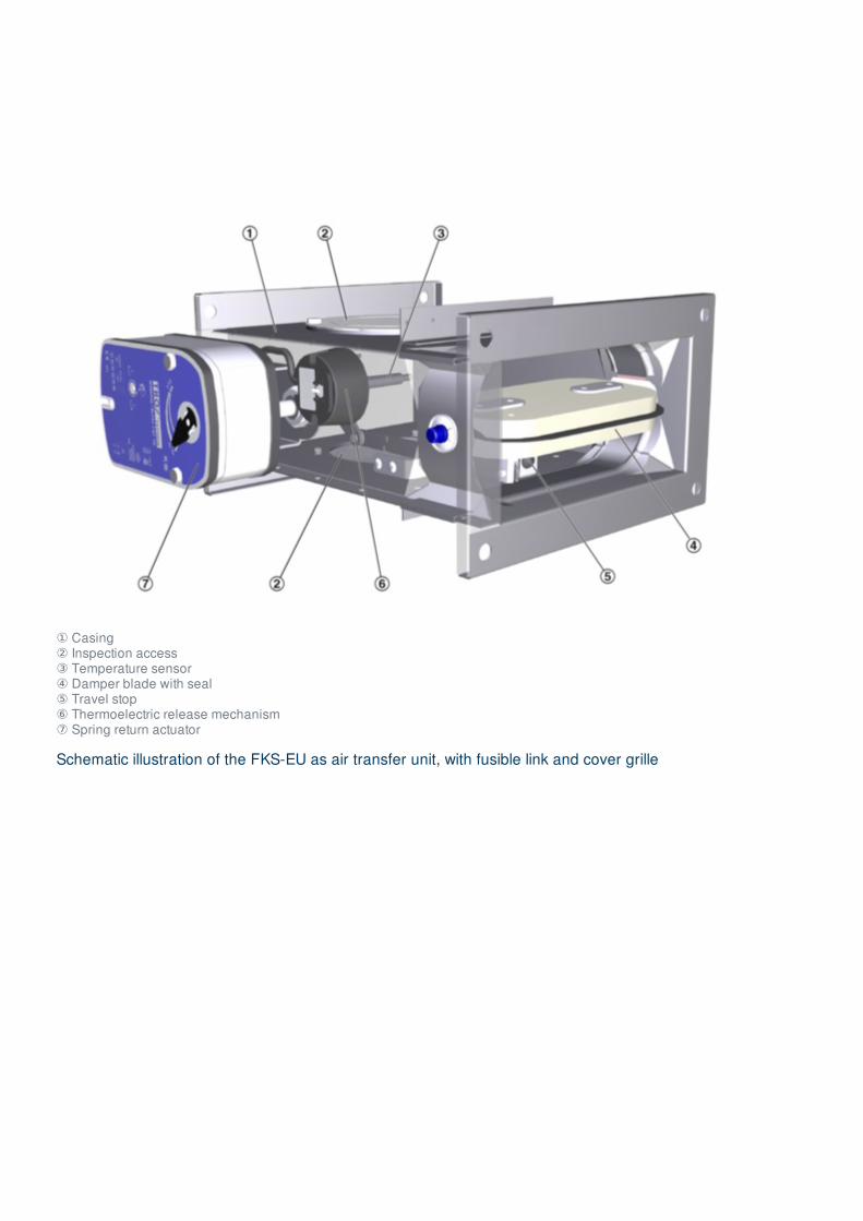
① Casing② Inspection access③ Temperature sensor④ Damper blade with seal⑤ Travel stop⑥ Thermoelectric release mechanism⑦ Spring return actuator
Schematic illustration of the FKS-EU as air transfer unit, with fusible link and cover grille

① Casing② Inspection access③ Fusible link④ Damper blade with seal⑤ Travel stop⑥ Handle with interlock and damper blade position indicator⑦ Release mechanism⑧ Cover grille⑨ Extension piece
Schematic illustration of FKS-EU as air transfer damper

① Casing② Inspection access③ Temperature sensor④ Damper blade with seal⑤ Travel stop⑥ Thermoelectric release mechanism⑦ Spring return actuator⑧ Cover grille⑨ Extension piece⑩ Duct smoke detector RM-O-3-D
Nominal sizes 200 × 100 to 800 × 200 mm
Casing length 300 mm
Volume flow rate range Up to 1600 l/s or up to 5760 m³/h
Differential pressure range Up to 1500 Pa
Operating temperature At least 0 – 50 °C **
Release temperature 72 °C or 95 °C (for warm air ventilation systems)
Upstream velocity* ≤ 8 m/s with standard construction; ≤ 10 m/s with spring return actuator
* Data applies to uniform upstream and downstream conditions for the fire damper
** Temperatures may differ for units with attachments; details for other applications are available on request.

Volume flow rate V [m³/h] at differential pressure Δpst < 35 Pa
H [mm] L [dB(A)]B [mm]
200 300 400 500 600 700 800
10035 300 480 660 840 1030 1230 1420
45 420 670 920 1180 1450 1720 2000
12535 410 650 890 1150 1400 1700 1940
45 570 900 1250 1600 1960 2350 2700
15035 520 830 1140 1470 1800 2140 2480
45 730 1160 1600 2060 2520 3000 3480
16035 570 900 1250 1600 1970 2340 2700
45 790 1260 1750 2240 2750 3280 3800
20035 760 1220 1690 2170 2660 3170 3680
45 1060 1700 2360 3040 3750 4430 5150
Volume flow rate V [l/s] at differential pressure Δpst < 35 Pa
H [mm] L [dB(A)]B [mm]
200 300 400 500 600 700 800
10035 83 133 183 233 286 342 394
45 117 186 256 328 403 478 556
12535 114 181 247 319 389 472 539
45 158 250 347 444 544 653 750
15035 144 231 317 408 500 594 689
45 203 322 444 572 700 833 967
16035 158 250 347 444 547 650 750
45 219 350 486 622 764 911 1056
20035 211 339 469 603 739 881 1022
45 294 472 656 844 1042 1231 1431
WA
WA
Rectangular or square fire dampers with flanges, for the isolation of duct penetrations between fire compartments.
Tested for fire resistance properties to EN 1366-2, with CE marking and declaration of performance according to the ConstructionProducts Regulation.
Ready-for-operation unit, which includes a fire-resistant damper blade and a release mechanism. For mortar-based installationand dry mortarless installation into solid walls and ceiling slabs, lightweight partition walls and fire walls with cladding on bothsides; also in shaft walls with metal support structure and cladding on one side.
Casing length 300 mm, for the connection to ducts made of non-combustible or combustible materials. Thermal or thermoelectricrelease at 72 °C or 95 °C (warm air ventilation systems).
Constructions with spring return actuator for opening and closing the fire damper independent of the nominal size and even whilethe ventilation system is running, e.g. for a functional test.
Construction with installation block for easy dry mortarless installation.

Special characteristics
Declaration of performance according to Construction Products RegulationClassification to EN 13501-3, up to EI 120 (v , h , i ↔ o) SBuilding inspectorate licence Z-56.4212-991 for fire resistance propertiesComplies with the requirements of EN 15650Tested to EN 1366-2 for fire resistance propertiesHygiene complies with VDI 6022 part 1 (07/2011), VDI 3803 (10/2002), DIN 1946 part 4 (12/2008), and EN 13779 (09/2007)Corrosion protection according to EN 15650 in connection with EN 60068-2-52Closed blade air leakage to EN 1751, class 2Casing air leakage to EN 1751, class CLow differential pressure and sound power levelAny airflow directionIntegration into the central BMS with TROXNETCOM
Materials and surfaces
Casing:
Galvanised sheet steelGalvanised sheet steel, powder-coated RAL 7001Stainless steel 1.4301
Damper blade:
Special insulation materialSpecial insulation material with coating
Other components:
Damper blade shaft in stainless steelPlastic bearingsSeals of elastomer
The construction variants with stainless steel or powder-coated casing meet even more critical requirements for corrosionprotection. Detailed listing on request.
Technical dataNominal sizes: 200 × 100 mm – 800 × 200 mmCasing length: 300 mmVolume flow rate range: up to 1600 l/s or 5760 m³/hDifferential pressure: up to 1500 PaOperating temperature: at least 0 – 50 °C **Release temperature 72 °C or 95 °C (for use in warm air ventilation systems)Upstream velocity: ≤ 8 m/s with standard construction; ≤ 10 m/s * with actuator
* Data applies to uniform upstream and downstream conditions for the fire damper
** Temperatures may differ for units with attachments; details for other applications are available on request.
e o

Type
FKS-EU Fire damper
Construction
No entry: standard construction1 Powder-coated casing2 Stainless steel casing7 Coated damper blade1 – 7 Powder-coated casing and coated damperblade2 – 7 Stainless steel casing and coated damperbladeW¹ With fusible link 95 °C (only for use in warm airventilation systems)
Country of destination
DE Germany Other destination countries upon request
Nominal size [mm]
B × H × L
Accessories 1
No entry: noneE Installation blockB Cover plate
Accessories 2
No entry: noneA0 – SS
Attachments
Z00 – ZA12
¹ W can be combined with all constructions listed under , but not with
attachments Z43RM – Z45RM

Type
FKS-EU Fire damper
Construction
No entry: standard construction1 Powder-coated casing, RAL 70012 Stainless steel casing7 Coated damper blade1 – 7 Powder-coated casing, RAL 7001, and coated damper blade2 – 7 Stainless steel casing and coated damper blade
Country of destination
DE Germany Other destination countries upon request
Nominal size [mm]
B × H × L
Accessories 1
No entry: noneB Cover plate
Accessories 2
AA Cover grilles on both ends
Attachments
Z00 – Z03
Type
FKS-EU Air transfer damper
Construction
No entry: standard construction1 Powder-coated casing, RAL 70012 Stainless steel casing7 Coated damper blade1 – 7 Powder-coated casing, RAL 7001, and coated damper blade2 – 7 Stainless steel casing and coated damper blade
Country of destination
DE Germany Other destination countries upon request
Nominal size [mm]
B × H × L
Accessories 1
No entry: noneE Installation blockB Cover plate
Accessories 2
AA Cover grilles on both ends
Attachments
Z43RM – Z45RM
Homepage > Products > Fire and Smoke Protection > Fire dampers > Type FKS-EU
Home Contacts Imprint Delivery and payment terms Privacy Disclaimer 2019-02-10 © TROX GmbH

TROX GmbH
Heinrich-Trox-PlatzD-47504 Neukirchen-VluynTel.: +49 (0)2845 202-0Fax: +49 (0)2845 202-265
Online-Services
Order-Status (My TROX NET)
TROX Academy
Catalogue Download
Your contact partner
Online fault report
BIM
Service-Hotlines
Sales Germanyand technical consulting+49 (0)2845 202-0Contact
Technical service+49 (0)2845 202-400Contact
Homepage > Products > Fire and Smoke Protection > Fire dampers > Type FKS-EU
Home Contacts Imprint Delivery and payment terms Privacy Disclaimer 2019-02-10 © TROX GmbH