type tvlk©gulateurs-vav/type-tvlk...factory set-up or programming and aerodynamic function testing...
TRANSCRIPT

TYPE TVLK
OPTIMISED FOR USE IN LABORATORIES AND ON FUME CUPBOARDS
Plastic circular VAV terminal units for aggressive extract air in laboratories and production facilities
Casing and damper blade made of flame-resistant polypropylene
Compact construction, only 400 mm long
High control accuracy even in case of unfavourable upstream conditions
Combination with fast-running actuators (air management systems)
Volume flow rate measurement with bluff body or nozzle
Slide-out sensor tubes allow for easy cleaning
Closed blade air leakage to EN 1751, class 4
Casing air leakage to EN 1751, class C
Page d'accueil > Produits > Unité de régulation > Débit variable > Régulateurs VAV
> Type TVLK

Optional equipment and accessories
With flanges on both ends
Plastic secondary silencer Type CAK for the reduction of air-regenerated noise
APPLICATION
Application
Circular LABCONTROL VAV terminal units of Type TVLK, made of plastic, to
control the volume flow rate of fume cupboards and fume hoods
Suitable for contaminated air
Closed-loop volume flow control using an external power supply
Shut-off by means of switching (equipment supplied by others)
Special characteristics
High control accuracy even in case of unfavourable upstream conditions
Integral slide-out differential pressure sensor with 3 mm measuring holes (resistant
to dust and pollution)
No metal parts come into contact with the airflow
Factory set-up or programming and aerodynamic function testing
Volume flow rate can be measured and subsequently adjusted on site; additional
adjustment tool or configuration software may be necessary
Nominal sizes
Bluff body: 250 – 100, 250 – 160
Nozzle: 250 – D08, 250 – D10, 250 – D16
Bluff body available in two sizes and nozzle available in three sizes for different
volume flow rate ranges
DESCRIPTION
Variants
TVLK: VAV terminal unit

TVLK-FL: VAV terminal unit with flanges on both ends
Parts and characteristics
Ready-to-commission unit which consists of mechanical parts and control
components (attachments)
Averaging differential pressure sensor for volume flow rate measurement; can be
removed for cleaning
Damper blade
Factory assembled control components (attachments) complete with wiring and
tubing
Aerodynamic functional testing on a special test rig prior to shipping of each unit
Unit carries test label with relevant data
Attachments
LABCONTROL: Control components (attachments) for air management systems
Universal controller: Controller, differential pressure transducer and actuators for
special applications
Accessories
Matching flanges for both ends, including seals
Useful additions
Plastic secondary silencer Type CAK for demanding acoustic requirements
Construction features
Circular casing
Short casing: 392 mm without flange, 400 mm with flange
Spigot suitable for ducts according to DIN 8077
Both spigots with same diameter (250 mm)
Position of the damper blade indicated externally at shaft extension
Materials and surfaces
Casing and damper blade made of flame-resistant polypropylene (PP),
INFORMATION TECHNIQUE
Function, Technical data, Quick sizing, Specification text, Order code, Related Products
flammability to UL 94, V-0
Differential pressure sensor (with bluff body, or nozzle) and plain bearing made of
polypropylene (PP)
Damper blade seal made of thermoplastic elastomers (TPE)
Standards and guidelines
Hygiene conforms to VDI 6022
Closed blade air leakage to EN 1751, class 4
Meets the increased requirements of DIN 1946, part 4, with regard to the
acceptable closed blade air leakage
Casing air leakage to EN 1751, class C
Maintenance
Maintenance-free as construction and materials are not subject to wear
Zero point correction of the static differential pressure transducer should be carried
out once per year (recommendation)
FUNCTION
Functional description
For measuring the volume flow rate the VAV terminal unit is fitted either with a bluff body and a differential pressure
sensor or with a nozzle.
The control components (attachments) include a differential pressure transducer that transforms the differential pressure
(effective pressure) into an electric signal, a controller, and an actuator.
Fume cupboard control: The volume flow rate setpoint depends on the control strategy for the fume cupboard and is
based on the face velocity, the sash position, or a constant value.
Volume flow control: The volume flow rate setpoint comes from an external unit.

The controller compares the actual value with the setpoint value and alters the control signal of the actuator if there is a
difference between the two values.
Schematic illustration of the TVLK
① Düse (optional)② Anbaugruppe EASYLAB③ Gehäuse④ Stellantrieb⑤ Staukörper und Sensorrohre
TECHNICAL DATA

Volume flow rate ranges
The minimum differential pressure of VAV terminal units is an important factor in designing the ductwork and in rating the fan
including speed control.
Sufficient duct pressure must be ensured for all operating conditions and for all control units. The measurement points for fan
speed control must be selected accordingly.
The volume flow rates given for VAV terminal units depend on the nominal size and on the control component (attachment) that
is installed. The table gives the minimum and maximum values for a VAV terminal unit. Some control components may only
have a limited volume flow rate range. This applies in particular to control components with a static differential pressure
transducer. For volume flow rate ranges for all control components refer to our Easy Product Finder design programme.
TVLK with EASYLAB, volume flow rate ranges and minimum differential pressures

Nominal sizeV
l/s
V
m³/h
①
Δp
Pa
②
Δp
Pa
③
Δp
Pa
④
Δp
Pa
ΔV
± %
250-10055 198 5 5 5 5 10
140 504 15 15 15 15 7
250-100220 792 35 35 35 35 6
360 1296 85 85 85 90 5
250-16030 108 5 5 5 5 10
80 288 25 25 25 25 7
250-160120 432 50 50 50 50 6
195 702 130 130 130 130 5
250-D0895 342 5 5 5 5 10
210 756 10 10 10 10 7
250-D08315 1134 20 20 20 20 6
515 1854 45 50 55 55 5
250-D1055 198 5 5 5 5 10
140 504 10 10 10 10 7
250-D10220 792 20 20 20 20 6
360 1296 50 50 55 55 5
250-D1630 108 5 5 5 5 10
80 288 15 15 15 15 7
250-D16120 432 30 30 30 30 6
195 702 70 70 75 75 5
TVLK with Universal controller, volume flow rate ranges and minimum differential pressures
st min st min st min st min

Nominal sizeV
l/s
V
m³/h
①
Δp
Pa
②
Δp
Pa
③
Δp
Pa
④
Δp
Pa
ΔV
± %
250-10065 234 5 5 5 5 10
180 648 25 25 25 25 7
250-100290 1044 55 55 55 60 6
360 1296 85 85 85 90 5
250-16035 126 5 5 5 5 10
100 360 35 35 35 35 7
250-160160 576 90 90 90 90 6
195 702 130 130 130 130 5
250-D0895 342 5 5 5 5 10
210 756 10 10 10 10 7
250-D08315 1134 20 20 20 20 6
515 1854 45 50 55 55 5
250-D1065 234 5 5 5 5 10
180 648 15 15 15 15 7
250-D10290 1044 35 35 35 35 6
360 1296 50 50 55 55 5
250-D1635 126 5 5 5 5 10
100 360 20 20 20 20 7
250-D16160 576 50 50 50 50 6
195 702 70 70 75 75 5
st min st min st min st min

Nominal sizes 250 mm
Volume flow rate range 30 – 515 l/s or 108 – 1854 m³/h
Volume flow rate control range Approx. 15 to 100% of the nominal volume flow rate
Minimum differential pressure 5 – 130 Pa
Maximum differential pressure 1000 Pa
Operating temperature 10 – 50 °C
QUICK SIZING
Quick sizing tables provide a good overview of the room sound pressure levels that can be expected. Approximate intermediate
values can be interpolated. Precise intermediate values and spectral data can be calculated with our Easy Product Finder
design programme.
The first selection criteria for the nominal size are the actual volume flow rates V and V . The quick sizing tables are based
on generally accepted attenuation levels. If the sound pressure level exceeds the required level, a larger air terminal unit and/or
a silencer is required.
TVLK with EASYLAB, Sound pressure level at differential pressure 150 Pa
Nominal size VAir-regenerated noise Case-radiated noise
① ② ③ ④ ①
Nominal sizeV L L L
l/s m³/h dB(A)
55 198 40 33 29 26 26
min max
PA PA1 PA2

250-100 140 504 46 38 34 31 33
250-100220 792 47 39 35 31 37
360 1296 48 39 35 32 42
250-16030 108 37 32 28 25 22
80 288 41 35 31 28 29
250-160120 432 43 37 33 30 32
195 702 49 42 38 35 40
250-D0895 342 36 26 23 20 23
210 756 40 31 27 24 29
250-D08315 1134 41 32 29 26 33
515 1854 44 34 31 28 38
250-D1055 198 36 28 24 21 24
140 504 42 34 30 27 31
250-D10220 792 43 35 31 28 35
360 1296 45 37 33 29 38
250-D1630 108 33 28 24 22 21
80 288 39 33 30 28 28
250-D16120 432 42 36 33 30 31
195 702 47 42 38 36 38
① TVLK
② TVLK with circular silencer CAK, insulation thickness 50 mm, length 500 mm

③ TVLK with circular silencer CAK, insulation thickness 50 mm, length 1000 mm
④ TVLK with circular silencer CAK, insulation thickness 50 mm, length 1500 mm
TVLK with VARYCONTROL Universal controller, Sound pressure level at differential pressure 150 Pa
Nominal size VAir-regenerated noise Case-radiated noise
① ② ③ ④ ①
Nominal sizeV L L L
l/s m³/h dB(A)
250-10065 234 41 34 30 27 27
180 648 46 38 34 31 35
250-100290 1044 47 39 35 31 40
360 1296 48 39 35 32 42
250-16035 126 38 33 29 26 23
100 360 42 36 32 29 30
250-160160 576 45 37 34 31 34
195 702 49 42 38 35 40
250-D0895 342 36 26 23 20 23
210 756 40 31 27 24 29
250-D08315 1134 41 32 29 26 33
515 1854 44 34 31 28 38
250-D1065 234 37 30 26 22 25
180 648 43 35 31 28 33
250-D10
290 1044 44 36 32 29 36
PA PA1 PA2

360 1296 45 37 33 29 38
250-D1635 126 34 29 25 23 22
100 360 41 35 32 29 30
250-D16160 576 43 37 34 32 32
195 702 47 42 38 36 38
① TVLK
② TVLK with circular silencer CAK, insulation thickness 50 mm, length 500 mm
③ TVLK with circular silencer CAK, insulation thickness 50 mm, length 1000 mm
④ TVLK with circular silencer CAK, insulation thickness 50 mm, length 1500 mm
SPECIFICATION TEXT
Circular VAV terminal units made of flame-resistant plastic, for variable air volume systems and fume cupboards. Suitable for
the control of extract air containing aggressive media since all components coming into contact with the airflow are made of
plastic (no interior metal parts).
Ready-to-commission unit which consists of the mechanical parts and the electronic control components (attachments). Each
unit contains an averaging differential pressure sensor with bluff body or a nozzle for volume flow rate measurement, and a
damper blade. Factory assembled control components (attachments) complete with wiring and tubing.
Differential pressure sensor with 3 mm measuring holes (resistant to dust and pollution)
Spigot, suitable for ducts according to DIN 8077.
Position of the damper blade indicated externally at shaft extension.
Closed blade air leakage to EN 1751, class 4.
Casing air leakage to EN 1751, class C.
Special characteristics
High control accuracy even in case of unfavourable upstream conditions
Integral slide-out differential pressure sensor with 3 mm measuring holes (resistant to dust and pollution)
No metal parts come into contact with the airflow
Factory set-up or programming and aerodynamic function testing

Volume flow rate can be measured and subsequently adjusted on site; additional adjustment tool or configuration
software may be necessary
Materials and surfaces
Casing and damper blade made of flame-resistant polypropylene (PP), flammability to UL 94, V-0
Differential pressure sensor (with bluff body, or nozzle) and plain bearing made of polypropylene (PP)
Damper blade seal made of thermoplastic elastomers (TPE)
Technical data
Nominal sizes: 250 mm
Volume flow rate range: 30 to 515 l/s or 108 to 1854 m³/h
Volume flow rate control range: approx. 15 – 100 % of the nominal volume flow rate
Minimum differential pressure: 5 – 130 Pa
Maximum differential pressure: 1000 Pa
Attachments
Variable volume flow control with electronic EASYLAB controller for fume cupboards.
Supply voltage 24 V AC
Fast and stable control
Static differential pressure measurement
Fast-running actuator
Easy commissioning due to plug and play communication system
Controller is a modular system and can be expanded
Volume flow rate monitoring
Sizing data
V _______________________ [m³/h]
Δp _______________________ [Pa]
Air-regenerated noise
L _______________________ [dB(A)]
Case-radiated noise
st
PA

L _______________________ [dB(A)]
This specification text describes the general properties of the product. Texts for variants can be generated with our Easy Product
Finder design programme.
PA
ORDER CODE
Order example: TVLK/250-D16/BPG/E2/150-650
Nominal size 250 with nozzle D16
AttachmentUniversal controller with MP bus interface and static differential pressure transducer, fast-running
actuator
Operating mode Single
Operating
values150 – 650 m³/h
Order example: TVLK/250–100/ELAB/FH–VS/200–900 m³/h
Nominal size 250 with bluff body 100
Attachment EASYLAB controller with fast-running actuator
Equipment function Fume cupboard control with face velocity transducer
Volume flow rate 200 – 900 m³/h
Order example: TVLK/250-D08/ELAB/E2/400-1600
Nominal size 250 with nozzle D08
Attachment EASYLAB controller TCU3 with fast-running actuator
External volume flow rate setting Voltage signal 2 – 10 V DC
Operating values 400 – 1600 m³/h

Type
TVLK VAV
terminal unit, plastic
Flange
No entry: none
FL Flanges
on both ends
Nominal size
250 – 100 Bluff
body 100
250 – 160 Bluff
body 160
250 – D08
Nozzle D08
250 – D10
Nozzle D10
250 – D16
Nozzle D16
Attachments
(control component)
BB3 Universal
controller with static differential pressure transducer
BP3 Universal
controller with MP bus interface and static differential pressure
transducer
BPG Universal
controller with MP bus interface and static differential pressure
transducer, fast-running actuator
Operating mode
E Single
M Master
S Slave
F Constant
value
Signal voltage
range
For the actual and
setpoint value signals

Accessories
No entry: none
GK Matching
flanges for both ends
0 0 – 10 V DC
(only BP3 and BPG)
2 2 – 10 V DC
Volume flow
rates [m³/h or l/s]
V – V for
factory setting
Type
TVLK VAV
terminal unit, plastic
Flange
No entry: none
FL Flanges on
both ends
Nominal size
250 – 100 Bluff
body 100
Equipment
function
With face
velocity transducer
FH-
VS Face velocity control
With sash
distance sensor
FH-
DS Linear control strategy
FH-
DV Safety-optimised control strategy
With
switching steps for switch contacts provided by others
min max

250 – 160 Bluff
body 160
250 – D08
Nozzle D08
250 – D10
Nozzle D10
250 – D16
Nozzle D16
Accessories
No entry: none
GK Matching
flanges for both ends
Attachments
(control component)
ELAB EASYLAB
controller TCU3 with fast-running actuator
FH-
2P 2 switching steps
FH-
3P 3 switching steps
Without
signalling
FH-
F Volume flow rate constant value
Expansion
modules
Option 1:
Supply voltage
No entry:
24 V AC
T EM-
TRF for 230 V AC
U EM-
TRF-USV for 230 V AC, provides uninterruptible power supply
(UPS)
Option 2:
Communication interface
No entry:
none
L EM-
LON for LonWorks FTT-10A
B EM-
BAC-MOD-01 for BACnet MS/TP
M EM-
BAC-MOD-01 for Modbus RTU

I EM-
IP for BACnet/IP, Modbus/IP and webserver
R EM-
IP with real time clock
Option 3:
Automatic zero point correction
No entry:
none
Z EM-
AUTOZERO Solenoid valve for automatic zero point correction
Option 4:
Lighting
No entry:
none
S EM-
LIGHT Wired socket for the connection of lighting and for
switching the lighting on/off using the control panel (only with EM-
TRF or EM-TRF-USV)
Operating
values [m³/h or l/s]
Depending
on the equipment function
VS:
V – V
DS:
V – V
DV:
V – V
2P: V / V
3P:
V / V / V
min max
min max
min max
1 2
1 2 3

F: V
Useful
additions
Control
panel for fume cupboard controller, for displaying the functions of
the control system according to EN 14175
BE-SEG-
02 OLED display
BE-LCD-
01 40-character display
Type
TVLK VAV
terminal unit, plastic
Flange
No entry: none
FL Flanges on
both ends
Equipment
function
Single
operation
EC Extract
air controller
External
1

Nominal size
250 – 100 Bluff
body 100
250 – 160 Bluff
body 160
250 – D08
Nozzle D08
250 – D10
Nozzle D10
250 – D16
Nozzle D16
Accessories
No entry: none
GK Matching
flanges for both ends
Attachments
(control component)
ELAB EASYLAB
controller TCU3 with fast-running actuator
volume flow rate setting
E0 Voltage
signal 0 – 10 V DC
E2 Voltage
signal 2 – 10 V DC
2P Switch
contacts (provided by others) for 2 switching steps
3P Switch
contacts (provided by others) for 3 switching steps
F Volume
flow rate constant value, without signalling
Expansion
modules
Option 1:
Supply voltage
No entry:
24 V AC
T EM-TRF
for 230 V AC
U EM-TRF-
USV for 230 V AC, provides uninterruptible power supply (UPS)
Option 2:
Communication interface
No entry: none
L EM-LON
for LonWorks FTT-10A
B EM-BAC-
MOD-01 for BACnet MS/TP

M EM-
BAC-MOD-01 for Modbus RTU
I EM-IP for
BACnet/IP, Modbus/IP and webserver
R EM-IP
with real time clock
Option 3:
Automatic zero point correction
No entry: none
Z EM-
AUTOZERO Solenoid valve for automatic zero point correction
Operating
values [m /h or l/s, Pa]
E0, E2:
V / V
2P: V / V
3P: V / V / V
F: V
3
min max
1 2
1 2 3
1
Variants, Attachments, Dimensions and weight
RELATED PRODUCTS
AttachmentsType Universal, static
Type EASYLAB TCU3
Additional products
Type CAK
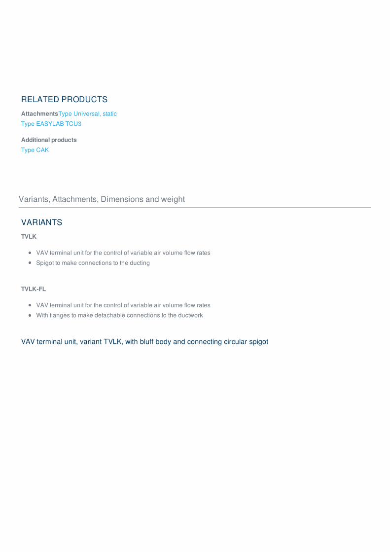
VARIANTS
TVLK
VAV terminal unit for the control of variable air volume flow rates
Spigot to make connections to the ducting
TVLK-FL
VAV terminal unit for the control of variable air volume flow rates
With flanges to make detachable connections to the ductwork
VAV terminal unit, variant TVLK, with bluff body and connecting circular spigot

VAV terminal unit, variant TVLK, with bluff body and flange

VAV terminal unit, variant TVLK, with nozzle and connecting circular spigot

VAV terminal unit, variant TVLK, with nozzle and flange

ATTACHMENTS
TVLK, VARYCONTROL control components
Order code detailControlled
variableController
Differential pressure
transducerActuator
Universal controller,
static
BP3Volume flow
rate
Universal controller with MP bus interface
TROX/BelimoStatic, integral Actuator
BPGVolume flow
rate
Universal controller with MP bus interface
TROX/BelimoStatic, integral
Fast-running
actuator
BB3Volume flow
rateUniversal controller TROX/Belimo Static, integral Actuator
TVLK, LABCONTROL control components
Order code
detailControlled variable Controller
Differential pressure
transducerActuator
EASYLAB
ELABFume cupboard Room supply air Room extract air Room
pressure Single controller
EASYLAB
controller TCU3Static, integral
Fast-running
actuator
Attachments: VARYCONTROL control components
☒Controlled
variableInterface
V -/ V
-
adjustment
Differential
pressure
transducer
Actuator Manufacturer LVC TVR TVJ TVTTZ-
S
TA-
STVZ TVA TVM TVRK TVLK
min max

Easy
controllerDynamic
Easy V Integral Integral ① ● ● ● ● ● ● ● ●
Compact
controllerDynamic
BC0 V MP bus Integral Integral ② ● ● ● ● ● ● ● ●
BF0 V MP bus Integral Integral ② ●
BL0 V LonWorks Integral Integral ② ● ● ● ● ● ● ●
BM0 V Modbus Integral Integral ②
BM0-
J6V
Modbus
and plug-in
connecting
cable
Integral Integral ②
XG0 V Integral Integral ③ ●
XB0 V Integral Integral ③ ● ● ● ● ● ● ●
LN0 V Integral Integral ⑤ ● ● ● ● ● ● ●
LK0 V KNX ⑤
LY0 V Integral Integral ⑤ ●
Compact
controllerStatic
SA0 V Integral Integral ④
SC0 Δp Integral
Fast-
running
actuator,
integral
④

Universal
controllerDynamic
B11 V Integral
Actuator,
torque
for TVT
② ●
B13 V Integral Actuator ② ● ● ● ● ● ●
B27 V Integral Actuator ② ●
B1B V Integral
Spring
return
actuator
② ● ● ● ● ● ● ●
XC3 V Integral
Spring
return
actuator
③ ● ● ● ● ● ● ●
Universal
controllerStatic
BP1 V MP busSeparate
part
Actuator,
torque
for TVT② ●
BP3 V MP busSeparate
partActuator ② ● ● ● ● ● ● ● ●
BPB V MP busSeparate
part
Spring
return
actuator
② ● ● ● ● ● ● ● ●
BPG V MP busSeparate
part
Fast-
running
actuator
② ● ● ● ● ● ● ● ● ●
BB1 VSeparate
part
Actuator,
torque
for TVT
② ●

BB3 VSeparate
partActuator ② ● ● ● ● ● ● ● ●
BBB VSeparate
part
Spring
return
actuator
② ● ● ● ● ● ● ●
XD1 V Integral Actuator ③ ● ● ● ● ● ● ● ●
XD3 V Integral
Spring
return
actuator
③ ● ● ● ● ● ● ● ●
BR1 Δp MP bus 100 Pa
Actuator,
torque
for TVT
② ●
BR3 Δp MP bus 100 Pa Actuator ② ● ● ● ● ● ● ●
BRB Δp MP bus 100 Pa
Spring
return
actuator
② ● ● ● ● ● ● ● ●
BRG Δp MP bus 100 Pa
Fast-
running
actuator
② ● ● ● ● ● ●
BS1 Δp MP bus 600 Pa
Actuator,
torque
for TVT
② ●
BS3 Δp MP bus 600 Pa Actuator ② ● ● ● ●
BSB Δp MP bus 600 Pa
Spring
return
actuator
② ● ● ● ●
BSG Δp MP bus 600 Pa
Fast-
running
actuator
② ● ● ● ●
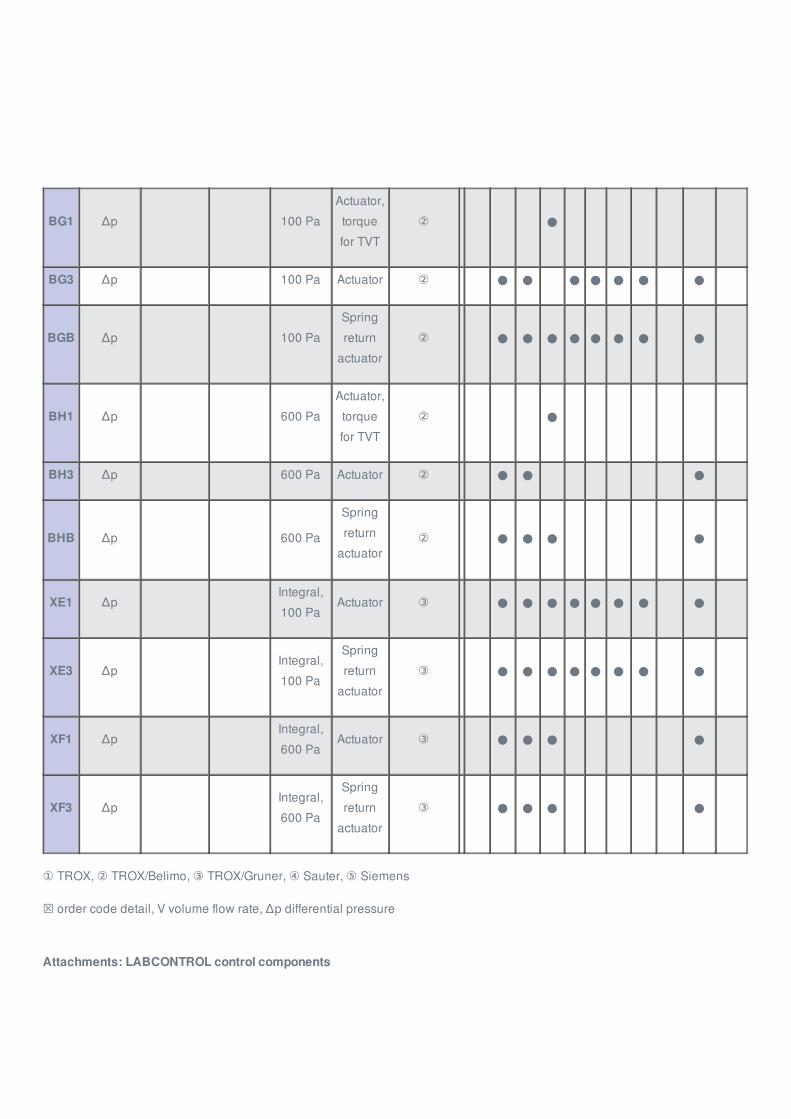
BG1 Δp 100 Pa
Actuator,
torque
for TVT
② ●
BG3 Δp 100 Pa Actuator ② ● ● ● ● ● ● ●
BGB Δp 100 Pa
Spring
return
actuator
② ● ● ● ● ● ● ● ●
BH1 Δp 600 Pa
Actuator,
torque
for TVT
② ●
BH3 Δp 600 Pa Actuator ② ● ● ●
BHB Δp 600 Pa
Spring
return
actuator② ● ● ● ●
XE1 ΔpIntegral,
100 PaActuator ③ ● ● ● ● ● ● ● ●
XE3 ΔpIntegral,
100 Pa
Spring
return
actuator
③ ● ● ● ● ● ● ● ●
XF1 ΔpIntegral,
600 PaActuator ③ ● ● ● ●
XF3 ΔpIntegral,
600 Pa
Spring
return
actuator
③ ● ● ● ●
① TROX, ② TROX/Belimo, ③ TROX/Gruner, ④ Sauter, ⑤ Siemens
☒ order code detail, V volume flow rate, Δp differential pressure
Attachments: LABCONTROL control components

☒ Controlled variable InterfaceV -/ V -
adjustment
Differential
pressure
transducer
Actuator TVR TVJ TVTTZ-
S
TA-
STVZ TVA TVRK TVLK
Easylab
controllerStatic
Elab
Room supply air
Room extract air
Room pressure
Single controller
TCU3 Integral
Fast-
running
actuator
● ● ●
Room supply air
Room pressure
Single controller
TCU3 Integral
Fast-
running
actuator
● ●
Elab
Room extract air
Room pressure
Single controller
TCU3 Integral
Fast-
running
actuator
● ●
Room supply air
Room extract air
Room pressure
Fume cupboard
Single controller
TCU3 Integral
Fast-
running
actuator
● ●
Electronic
controllerStatic
min max

TMA
Room supply air
Room extract air
Room pressure
TCU-LON-II with
LonWorks
interface
IntegralFast-running
actuator● ● ●
TMB
Fast-running
actuator
(brushless motor)
● ● ●
TMA
Room supply air
Room pressure
TCU-LON-II with
LonWorks
interface
IntegralFast-running
actuator● ●
TMB
Fast-running
actuator
(brushless motor)
● ●
TMA
Room extract air
Room pressure
TCU-LON-II with
LonWorks
interface
IntegralFast-running
actuator● ●
TMB
Fast-running
actuator
(brushless motor)
● ●
TMA
Room supply air
Room extract air
Room pressure
Fume cupboard
TCU-LON-II with
LonWorks
interface
IntegralFast-running
actuator● ●
TMB
Fast-running
actuator
(brushless motor)
● ●

DIMENSIONS AND WEIGHT
Nominal sizem
kg
250 5.1
Nominal sizem
kg
250 5.7
TVLK
TVLK-FL
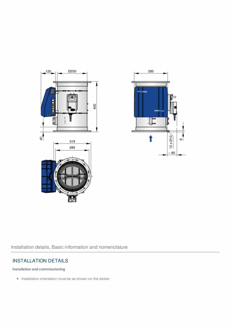
Installation details, Basic information and nomenclature
INSTALLATION DETAILS
Installation and commissioning
Installation orientation must be as shown on the sticker

Upstream conditions
The volume flow rate accuracy ΔV applies to a straight upstream section of the duct. Bends, junctions or a narrowing or
widening of the duct cause turbulence that may affect measurement. Duct connections, e.g. branches off the main duct,
must comply with EN 1505. Some installation situations require straight duct sections upstream.
Space required for commissioning and maintenance
Sufficient space must be kept clear near any attachments to allow for commissioning and maintenance. It may be
necessary to provide sufficiently sized inspection access openings.
Space requirement, control component on one side
Attachments① ② ③
mm
VARYCONTROL
Universal controller 300 320 300
Space requirement, control components on two sides
Attachments① ② ③ ④ ⑤ ⑥
mm
LABCONTROL
EASYLAB 350 350 400 300 250 300
Space required for cleaning the sensor tubes
Nominal size① ② ③
mm
250-1** Bluff body 100 160 D
250-D** Nozzle 100 160 100
D: Casing diameter

Bend
A bend with a centre line curvature radius of at least 1D – without an additional straight duct section upstream of the VAV
terminal unit – has only a negligible effect on the volume flow rate accuracy.
Junction

The stated volume flow rate accuracy ΔV will be achieved even when the VAV terminal unit is installed in a branch just off
the main duct. Even the installation on the dome of a fume cupboard will have no adverse effect.
Access to attachments

Access to attachments
Access to sensor tubes for cleaning

Access to battery pack

Separate space for fixing and accessing the battery pack (LABCONTROL EASYLAB accessory)
BASIC INFORMATION AND NOMENCLATURE
Principal dimensions
ØD [mm]
VAV terminal units made of stainless steel: Outside diameter of the spigot
VAV terminal units made of plastic: Inside diameter of the connecting spigot
ØD₁ [mm]
Pitch circle diameter of flanges
ØD₂ [mm]
Outside diameter of flanges

ØD₄ [mm]
Inside diameter of the screw holes of flanges
L [mm]
Length of unit including connecting spigot
L₁ [mm]
Length of casing or acoustic cladding
B [mm]
Duct width
B₁ [mm]
Screw hole pitch of flange (horizontal)
B₂ [mm]
Outside dimension of flange (width)
B₃ [mm]
Width of device
H [mm]
Duct height
H₁ [mm]
Screw hole pitch of flange (vertical)
H₂ [mm]
Outside dimension of flange (height)
H₃ [mm]
Unit height
n [ ]
Number of flange screw holes
T [mm]

Flange thickness
m [kg]
Unit weight including the minimum required attachments (e.g. Compact controller)
Acoustic data
f [Hz]
Octave band centre frequency
L [dB(A)]
A-weighted sound pressure level of air-regenerated noise of the VAV terminal unit, system attenuation taken into account
L [dB(A)]
A-weighted sound pressure level of air-regenerated noise of the VAV terminal unit with secondary silencer, system
attenuation taken into account
L [dB(A)]
A-weighted sound pressure level of case-regenerated noise of the VAV terminal unit, system attenuation taken into
account
L [dB(A)]
A-weighted sound pressure level of case-regenerated noise of the VAV terminal unit with acoustic cladding, system
attenuation taken into account
All sound pressure levels are based on 20 µPa.
Volume flow rates
V [m³/h] and [l/s]
Nominal volume flow rate (100 %)
The value depends on product type and nominal size
Values are published on the internet and in technical leaflets, and stored in the Easy Product Finder design
software.
Reference value for calculating percentages (e.g. V )
Upper limit of the setting range and maximum volume flow rate setpoint value for the VAV terminal unit
m
PA
PA1
PA2
PA3
nom
max

V [m³/h] and [l/s]
Technically possible minimum volume flow rate
The value depends on product type, nominal size and control component (attachment)
Values are stored in the Easy Product Finder design software
Lower limit of the setting range and minimum volume flow rate setpoint value for the VAV terminal unit
Depending on the controller, setpoint values below V (if V equals zero) may result in unstable control or
shut-off
V [m³/h] and [l/s]
Upper limit of the operating range for the VAV terminal unit that can be set by customers
V can only be smaller than or equal to V
In case of analogue signalling to volume flow controllers (which are typically used), the set maximum value (V ) is
allocated to the setpoint signal maximum (10 V) (see characteristic)
V [m³/h] and [l/s]
Lower limit of the operating range for the VAV terminal unit that can be set by customers
V should be smaller than or equal to V
Do not set V smaller than V , otherwise the control may become unstable or the damper blade may close
V may equal zero
In case of analogue signalling to volume flow controllers (which are typically used), the set minimum value (V ) is
allocated to the setpoint signal minimum (0 or 2 V) (see characteristic)
V [m³/h] and [l/s]
Volume flow rate
ΔV [± %]
Volume flow rate tolerance from setpoint value
ΔV [± %]
Volume flow rate tolerance for the warm air flow of dual duct terminal units
Differential pressure
Δp [Pa]
min unit
min unit min
max
max nom
max
min
min max
min min unit
min
min
warm
st

Static differential pressure
Δp [Pa]
Static differential pressure, minimum
The static minimum differential pressure is equal to the pressure loss of the VAV terminal unit when the damper
blade is open, caused by flow resistance (sensor tubes, damper mechanism)
If the pressure on the VAV terminal unit is too low, the setpoint volume flow rate may not be achieved, not even
when the damper blade is open
Important factor in designing the ductwork and in rating the fan including speed control
Sufficient duct pressure must be ensured for all operating conditions and for all terminal units, and the measurement
point or points for speed control must have been selected accordingly to achieve this
Construction
Galvanised sheet steel
Casing made of galvanised sheet steel
Parts in contact with the airflow as described for the product type
External parts, e.g. mounting brackets or covers, are usually made of galvanised sheet steel
Powder-coated surface (P1)
Casing made of galvanised sheet steel, powder-coated RAL 7001, silver grey
Parts in contact with the airflow are powder-coated or made of plastic
Due to production, some parts that come into contact with the airflow may be stainless steel or aluminium, powder-
coated
External parts, e.g. mounting brackets or covers, are usually made of galvanised sheet steel
Stainless steel (A2)
Casing made of stainless steel 1.4201
Parts in contact with the airflow are powder-coated or made of stainless steel
External parts, e.g. mounting brackets or covers, are usually made of galvanised sheet steel
Definition of noise
st min

① Air-regenerated noise② Case-radiated noise
Static differential pressure
Page d'accueil > Produits > Unité de régulation > Débit variable > Régulateurs VAV
> Type TVLK
Home Contacts Imprint Conditions de livraison et de paiement Confidentialité Réserve
05.06.2018 © TROX
HESCO Schweiz AG

TROX HESCO Schweiz AG
Walderstrasse 125
Case postale 455
CH-8630 Rüti ZH
Tél. +41 55 250 71 11
Fax. +41 55 250 73 10
Online-Services
État des commandes (MonTROXNET)
FAQ
Conditions de livraison et depaiement
Contact
Numéro de service
Numéro de service
Tél. +41 55 250 72 66
Page d'accueil > Produits > Unité de régulation > Débit variable > Régulateurs VAV
> Type TVLK
Home Contacts Imprint Conditions de livraison et de paiement Confidentialité Réserve
05.06.2018 © TROX
HESCO Schweiz AG