uca and 61850 for dummies v12
TRANSCRIPT
1
1
Douglas ProudfootSiemens Power Transmission and
Distribution
UCA and
61850 For
DUMMIES
This presentation is intended as a primer for anyone with little or no knowledge of UCA or 61850. As such, it does not examine the protocols in any great depth. Readers interested in learning more about the protocols are encouraged to consult the references on the last slide of this presentation. Some poetic license has been taken with terminology to keep the explanation of concepts as simple as possible.
This presentation makes use of animation on several slides, so readers viewing a hardcopy of this presentation may lose some of the context.

2
© Siemens Power Transmission & Distribution, 2002 2
Frame of ReferenceIntra-Substation Communications
SCAD
A Pr
otoc
ol(to
EM
S/SC
ADA
Substation Controller(s)
IED(s)
SwitchgearCTs & PTs
Communications Architecture
HMI(s)
This architecture will be used extensively throughout the rest of this presentation to discuss concepts. It represents a “typical” SA system:•Apparatus (switchgear and associated CTs and PTs)•Intelligent Electronic Devices (IEDs)•Substation Human Machine Interface (HMI)•Substation Controller. The last two are optional and either, none or both may be present. The Substation Controller may be PC-based (in which case the HMI and Substation Controller may be the same entity), RTU, PLC, Data Concentrator, or a hybrid of the above.Substation Controller tasks can include collating data from the IEDs, performing system-wide logic, system time synchronization, filtering and pre-processing of data, and presentation of substation data to remote clients (network control center et al). In a truly flat architecture where the above functions are not required, the IEDs may couple directly to the remote client(s). The discussions that follow do not examine that alternative but the concepts we will review are portable to this architecture – just replace the local client with a remote client. The cloud represents the communications infrastructure that integrates the IEDs into the HMI and/or Substation Controller.
3
© Siemens Power Transmission & Distribution, 2002 3
Frame of ReferenceStation Bus
Substation Controller(s)
IED(s)
HMI(s)
SwitchgearCTs & PTs
Station Bus
SCAD
A Pr
otoc
ol(to
EM
S/SC
ADA
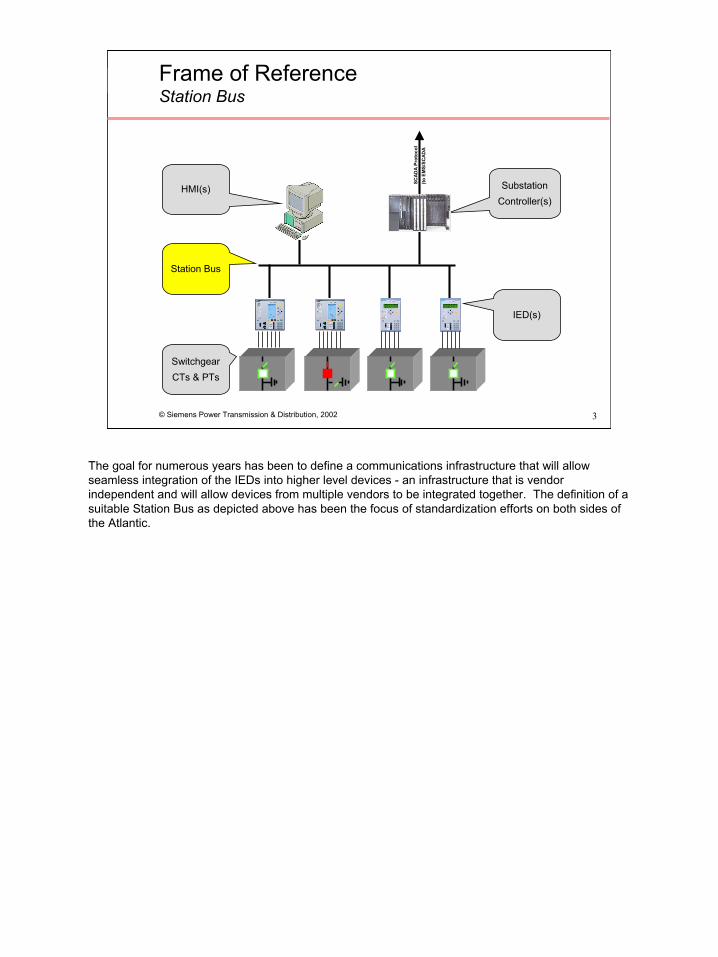
The goal for numerous years has been to define a communications infrastructure that will allow seamless integration of the IEDs into higher level devices - an infrastructure that is vendor independent and will allow devices from multiple vendors to be integrated together. The definition of a suitable Station Bus as depicted above has been the focus of standardization efforts on both sides of the Atlantic.
4
© Siemens Power Transmission & Distribution, 2002 4
Two Standards EmergeUCA and 61850
1994 1996
61850
UCA 2.0
1997 2003EPRI
IEEE, USIIEC TC57
UCA 2.0
IEC 61850
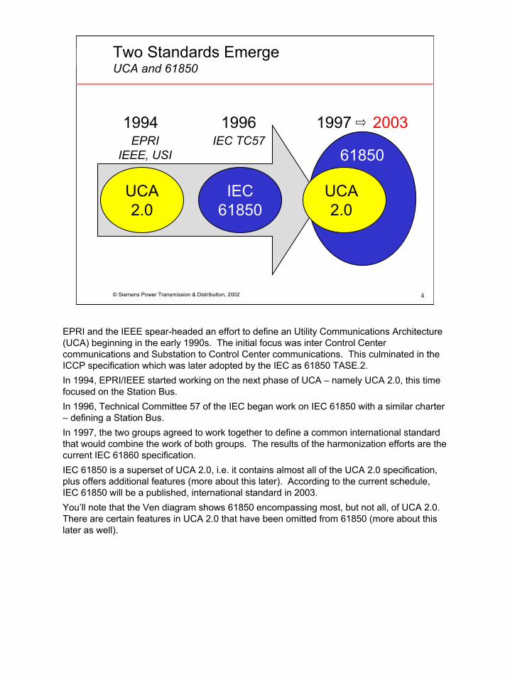
EPRI and the IEEE spear-headed an effort to define an Utility Communications Architecture (UCA) beginning in the early 1990s. The initial focus was inter Control Center communications and Substation to Control Center communications. This culminated in the ICCP specification which was later adopted by the IEC as 61850 TASE.2. In 1994, EPRI/IEEE started working on the next phase of UCA – namely UCA 2.0, this time focused on the Station Bus. In 1996, Technical Committee 57 of the IEC began work on IEC 61850 with a similar charter – defining a Station Bus. In 1997, the two groups agreed to work together to define a common international standard that would combine the work of both groups. The results of the harmonization efforts are the current IEC 61860 specification. IEC 61850 is a superset of UCA 2.0, i.e. it contains almost all of the UCA 2.0 specification, plus offers additional features (more about this later). According to the current schedule, IEC 61850 will be a published, international standard in 2003.You’ll note that the Ven diagram shows 61850 encompassing most, but not all, of UCA 2.0. There are certain features in UCA 2.0 that have been omitted from 61850 (more about this later as well).
5
© Siemens Power Transmission & Distribution, 2002 5
Functional MappingUCA 2.0 into 61850
Common data classes and attributes
Abstract communication service interface (ACSI)
Lower Layers
61850-x-y
Compatible logical nodeand data objects
Mapping to MMS
Standard Data Types and Common Components
Common Class Definitions
GOMSFE
Device Models
UCA2
Common Application Service Model (CASM)
CASM
Generic Object Models for Substation and Feeder Equipment
8 – 1
7 - 2
7 - 3
7 - 4
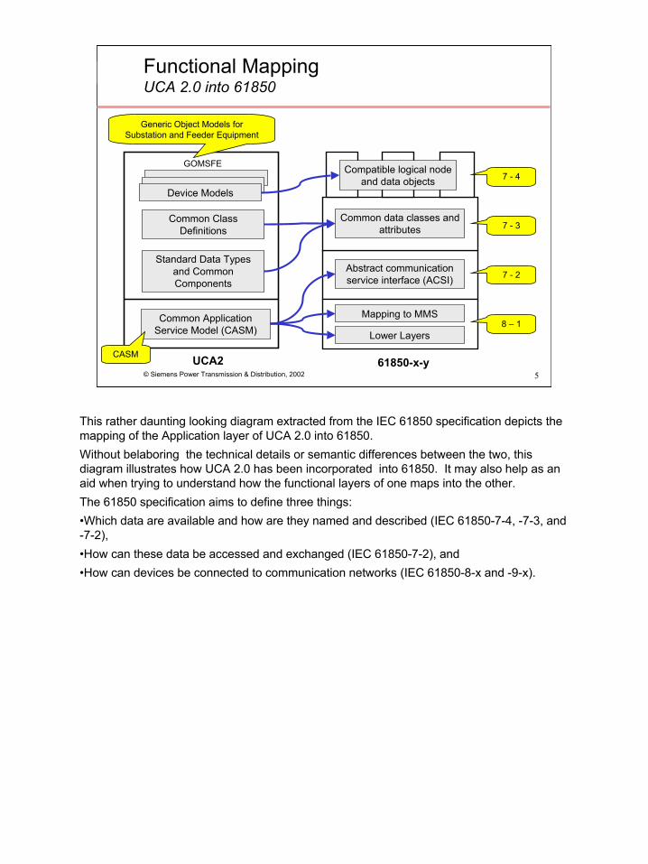
This rather daunting looking diagram extracted from the IEC 61850 specification depicts the mapping of the Application layer of UCA 2.0 into 61850. Without belaboring the technical details or semantic differences between the two, this diagram illustrates how UCA 2.0 has been incorporated into 61850. It may also help as an aid when trying to understand how the functional layers of one maps into the other.The 61850 specification aims to define three things:•Which data are available and how are they named and described (IEC 61850-7-4, -7-3, and -7-2),•How can these data be accessed and exchanged (IEC 61850-7-2), and•How can devices be connected to communication networks (IEC 61850-8-x and -9-x).

6
© Siemens Power Transmission & Distribution, 2002 6
Things to Remember
61850 is UCA 2.0 plus…1
This presentation aims to reinforce three (relatively) simple ideas; here’s the first:(1) IEC 61850 is UCA 2.0 plus additional functionality.
The rest of the presentation will concentrate on 61850 and it’s nomenclature. However, with the exception of some differences in terminology, the concepts are equally true.
While our discussions will focus on intra-substation communications, 61850 is intended for other applications as well. The specification states that the standard may also be applied to describe device models and functions for:•Substation to substation information exchange•Substation to control centre information exchange•Power Plant to control centre information exchange•Information exchange for distributed automation•Information exchange for metering
7
© Siemens Power Transmission & Distribution, 2002 7
Data Communication In “Human terms” (equates to ASCII protocol)
CB1
IED1IED 1 Data
“67 TOC Pick-up”
“CB1 is Closed”
“I Phase A is 200A”
“V Phase A is 26.3kV”
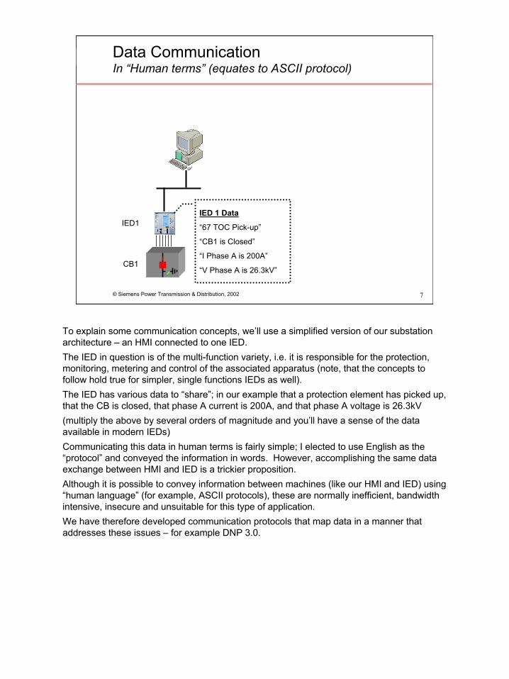
To explain some communication concepts, we’ll use a simplified version of our substation architecture – an HMI connected to one IED. The IED in question is of the multi-function variety, i.e. it is responsible for the protection, monitoring, metering and control of the associated apparatus (note, that the concepts to follow hold true for simpler, single functions IEDs as well). The IED has various data to “share”; in our example that a protection element has picked up, that the CB is closed, that phase A current is 200A, and that phase A voltage is 26.3kV(multiply the above by several orders of magnitude and you’ll have a sense of the data available in modern IEDs)Communicating this data in human terms is fairly simple; I elected to use English as the “protocol” and conveyed the information in words. However, accomplishing the same data exchange between HMI and IED is a trickier proposition. Although it is possible to convey information between machines (like our HMI and IED) using “human language” (for example, ASCII protocols), these are normally inefficient, bandwidth intensive, insecure and unsuitable for this type of application.We have therefore developed communication protocols that map data in a manner that addresses these issues – for example DNP 3.0.

8
© Siemens Power Transmission & Distribution, 2002 8
Data CommunicationUsing DNP 3.0
DN
P 3.
0 (to
EM
S/SC
ADA
DNP 3.0Multi-drop
bus
IED 1 Data
“67 TOC Pick-up”
“CB1 is Closed”
“I Phase A is 200A”
“V Phase A is 26.3kV”IED1, Obj 2, Var 2, #1 = CB1 Pos
IED1, Obj 2, Var 2, #20 = 67 TOC PU
IED1, Obj 30, Var 4, #1 = Ia
IED1, Obj 30, Var 4, #6 = Va
DNP 3.0 Messages
HMI LinkageCB1 Pos = DB DW 1
67 TOC PU = DB DW 2
Ia = DB DW 3
Va = DB DW 4
DB DW 1 = IED1, Obj 2, Var 2, #1
DB DW 2 = IED1, Obj 2, Var 2, #20
DB DW 3 = IED1, Obj 30, Var 4, #1
DB DW 4 = IED1, Obj 30, Var 4, #6
DNP Driver into DB
CB1
IED1
- Data context is lost
If we use DNP 3.0 as our Station Bus protocol there’s a three stage process to getting the data from the source to the destination:•The IED maps the “actual” data, e.g. “CB1 is Closed” into the appropriate DNP message, in this case, Object 2, Variant 2, Input #1 (Digital Input with time stamp). •The next time the HMI requests data from this IED, or the IED volunteers data (if unsolicited reporting is supported), this message is transmitted to the HMI where the content, i.e. the value of Obj2, Var2, #1 from IED1 are written into a database.•The HMI one line diagram contains a circuit breaker symbol, the state of which is being driven by the value in the database.The problem is that data context has been lost. Unless you record which “actual” data has been mapped into which DNP message, you have no way of regenerating this linkage. This requires the manual transfer of paper or electronic renditions of this mapping to enable the HMI supplier to populate the database and complete the link – which implies additional engineering/configuration time and introduces the possibility of error.
9
© Siemens Power Transmission & Distribution, 2002 9
Data Communication using 61850Think in terms of Logical “Groupings”
DN
P 3.
0 (to
EM
S/SC
ADA
61850LAN
IED 1 Data
“67 TOC Pick-up”
“CB1 is Closed”
“I Phase A is 200A”
“V Phase A is 26.3kV”
“Protection Data”
“Switchgear Data”
“Measurement Data”
“Measurement Data”CB1
IED1
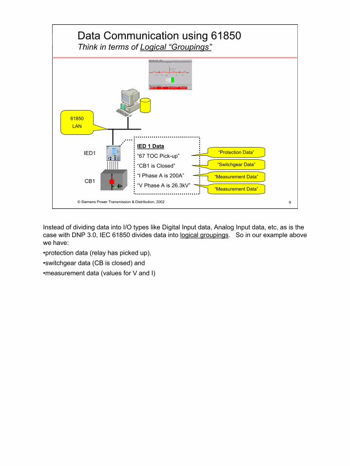
Instead of dividing data into I/O types like Digital Input data, Analog Input data, etc, as is the case with DNP 3.0, IEC 61850 divides data into logical groupings. So in our example above we have:•protection data (relay has picked up), •switchgear data (CB is closed) and •measurement data (values for V and I)
10
© Siemens Power Transmission & Distribution, 2002 10
Logical GroupingsThere are 13 different groups
ZFurther power system equipmentSSensors
XSwitchgearTInstrument Transformer
RProtection related functionsCSupervisory controlGGeneric ReferencesIInterfacing and Archiving
PProtection functions
MMetering and Measurement
YPower Transformer
AAutomatic Control
LSystem Logical Nodes
Group Designator
Logical Node Groups
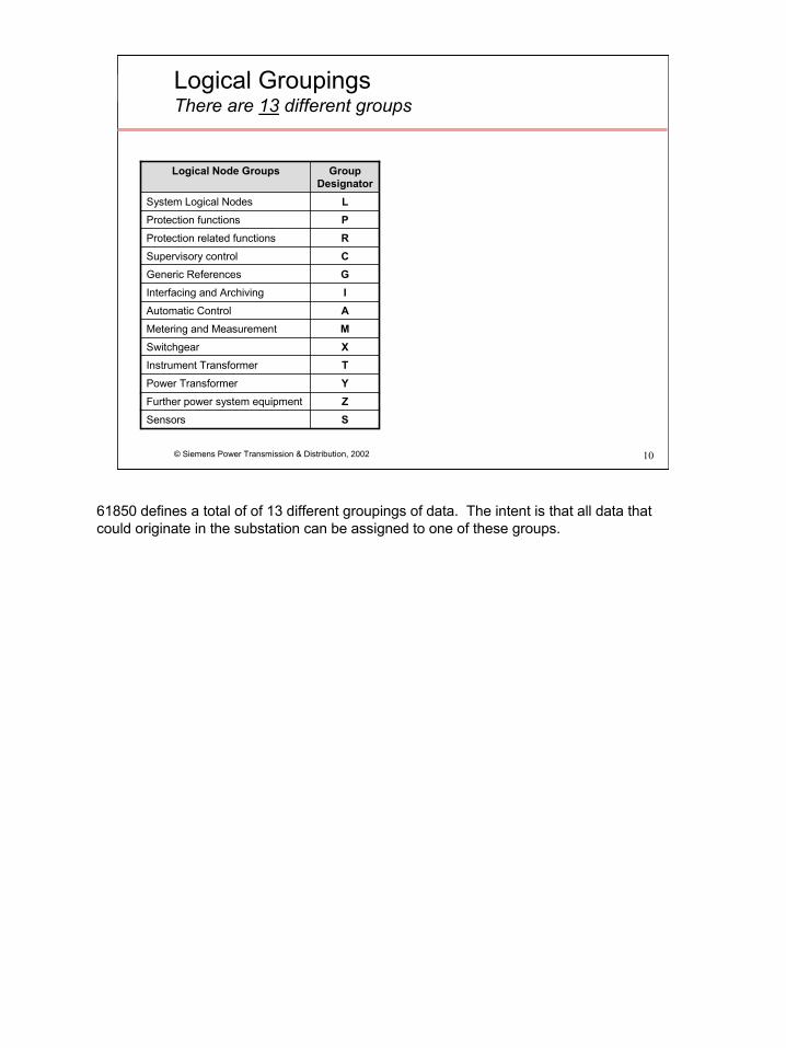
61850 defines a total of of 13 different groupings of data. The intent is that all data that could originate in the substation can be assigned to one of these groups.

11
© Siemens Power Transmission & Distribution, 2002 11
Logical NodesThere are 86 Logical Node Classes
14ZFurther power system equipment3SSensors86
4227443410272
Number
XSwitchgearTInstrument Transformer
RProtection related functionsCSupervisory controlGGeneric ReferencesIInterfacing and Archiving
PProtection functions
MMetering and Measurement
YPower Transformer
AAutomatic Control
LSystem Logical Nodes
Group Designator
Logical Node Groups
MMXU Measuring (Measurand unit)MMTR MeteringMSQI Sequence and ImbalanceMHAI Harmonics and Inter-harmonicsMDIF Differential Measurements…more
XCBR Circuit BreakerXSWI Circuit Switch
PDIR Directional elementPHAR Harmonic restraintPSCH Protection SchemePTEF Transient Earth FaultPZSU Zero speed or underspeedPDIS Distance protectionPVPH Volts per Hz relayPTUV UndervoltagePDOP Directional over power…more
Each of the groups are further subdivided into Logical Nodes. There are 86 different types of Logical Nodes defined. Each of these are composed of data that represent some application specific meaning and are intended to provide separate sub-categories of data (poetic license with terminology applied here). For example, The Protection Function group comprises 27 different Logical Nodes, some of these are listed above. To map this to the real world, data from a protective relay with 21 and 51 elements would be mapped to PTOC and PDIS logical nodes respectively.

12
© Siemens Power Transmission & Distribution, 2002 12
DataThere are 355 Data Classes
355
66Measurands14Metered values36Controllable Data85Status information
11Physical device information
130Settings
13System informationNumberData Classes A - Phase to ground amperes for Phases 1, 2, and 3
Amps - Current of a non three phase circuitAng - Angle between phase voltage and currentAnIn - Analogue Input used for generic I/OChAnVal - Array of analogue channel numbers and actual values at a certain time (time tag)CircA - Measured circulating current in a transformer paralleling applicationCtlV - Voltage on secondary of transformer as used for voltage control. Den - Density of gas or other insulating MediumDQ0Seq - Direct, quadrature, and zero axis quantity ECC - This is the measured current through a Petersen Coil in neutral compensated networks.FDkm - The distance to a fault in kilometresFDOhm - The distance to a fault in OhmsHaRmsA - Current Harmonic RMS (un-normalized THD) for A, B, C, NHaRmsV - Voltage Harmonic RMS (un-normalized THD) for AB, AN, BC, BN, CA, CN, NGHaTdA - Current Total Harmonic DistortionHaTdV - Voltage Total Harmonic DistortionMore…..
There are 355 different classes of data that are used to “construct” Logical Nodes. These data classes are divided amongst the 7 categories detailed above.

13
© Siemens Power Transmission & Distribution, 2002 13
Logical GroupingsDevices, nodes, classes and data
Physical Device(network address)
To illustrate how these device, logical nodes, classes and data concepts map to the real world, imagine an IED as a container.

14
© Siemens Power Transmission & Distribution, 2002 14
Logical GroupingsDevices, nodes, classes and data
Physical Device(network address)
Logical Device(IED1)
LN2(MMXU)
A
PhA
LN1(XCBR)
Pos
PhBStV q
Physical Device
Logical Device(1 to n)
Logical Node(1 to n)
Data Class
Data
The container is the Physical Device, it containsone or more Logical Devices, each of which contains
one or more Logical Nodes, each of which contains a pre-defined set of Data Classes, each of which contains
data.

15
© Siemens Power Transmission & Distribution, 2002 15
Defining DevicesPhysical Devices breakdown into Logical Nodes
CB1
IED1
PTOC Time Over Current
To return to our substation architecture, IED1 is a multi-function IED and supports the following features:Protection (Time Over Current, 51) PTOC LN

16
© Siemens Power Transmission & Distribution, 2002 16
Defining DevicesPhysical Devices breakdown into Logical Nodes
CB1
IED1
PTOC
RREC Auto Reclosing
IED1 is a multi-function IED and supports the following features:
Protection (Time Over Current, 51) PTOC LN
Protection related (Autoreclosing, 79) RREC LN

17
© Siemens Power Transmission & Distribution, 2002 17
Defining DevicesPhysical Devices breakdown into Logical Nodes
CB1
IED1
PTOC
RREC
XCBR CSWICircuit Breaker
Indication & Control
IED1 is a multi-function IED and supports the following features:
Protection (Time Over Current, 51) PTOC LN
Protection related (Autoreclosing, 79) RREC LNMonitoring of CB XCBR LNControl of CB CSWI LN

18
© Siemens Power Transmission & Distribution, 2002 18
Defining DevicesPhysical Devices breakdown into Logical Nodes
CB1
IED1
PTOC
RREC
XCBR
XSWI
CSWI
CSWIDisconnect SwitchIndication & Control
IED1 is a multi-function IED and supports the following features:
Protection (Time Over Current, 51) PTOC LN
Protection related (Autoreclosing, 79) RREC LNMonitoring of CB XCBR LNControl of CB CSWI LNMonitoring of Disconnect Switch XSWI LNControl of Disconnect Switch CSWI LN

19
© Siemens Power Transmission & Distribution, 2002 19
Defining DevicesPhysical Devices breakdown into Logical Nodes
CB1
IED1
PTOC
RREC
XCBR
XSWI
MMXU Measurement Unit
CSWI
CSWI
IED1 is a multi-function IED and supports the following features:
Protection (Time Over Current, 51) PTOC LN
Protection related (Autoreclosing, 79) RREC LNMonitoring of CB XCBR LNControl of CB CSWI LNMonitoring of Disconnect Switch XSWI LNControl of Disconnect Switch CSWI LNMeasurement (V, A, W, etc) MMXU LS
20
© Siemens Power Transmission & Distribution, 2002 20
Defining DevicesPhysical Devices breakdown into Logical Nodes
CB1
IED1
PTOC
RREC
XCBR
XSWI
MMXU
MMTR Metering
CSWI
CSWI
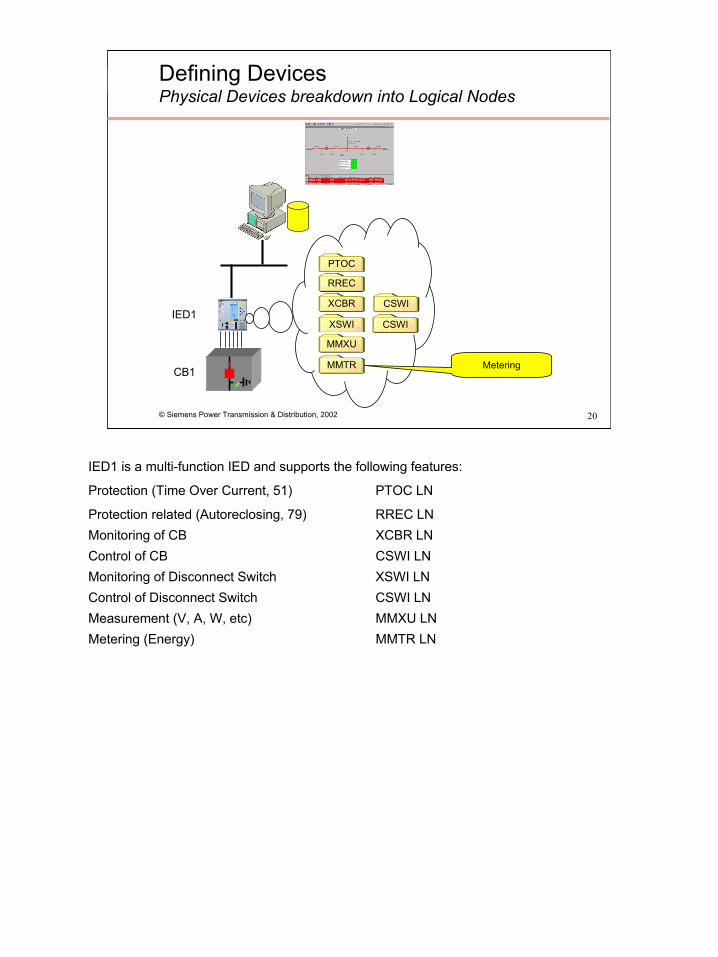
IED1 is a multi-function IED and supports the following features:
Protection (Time Over Current, 51) PTOC LN
Protection related (Autoreclosing, 79) RREC LNMonitoring of CB XCBR LNControl of CB CSWI LNMonitoring of Disconnect Switch XSWI LNControl of Disconnect Switch CSWI LNMeasurement (V, A, W, etc) MMXU LNMetering (Energy) MMTR LN
21
© Siemens Power Transmission & Distribution, 2002 21
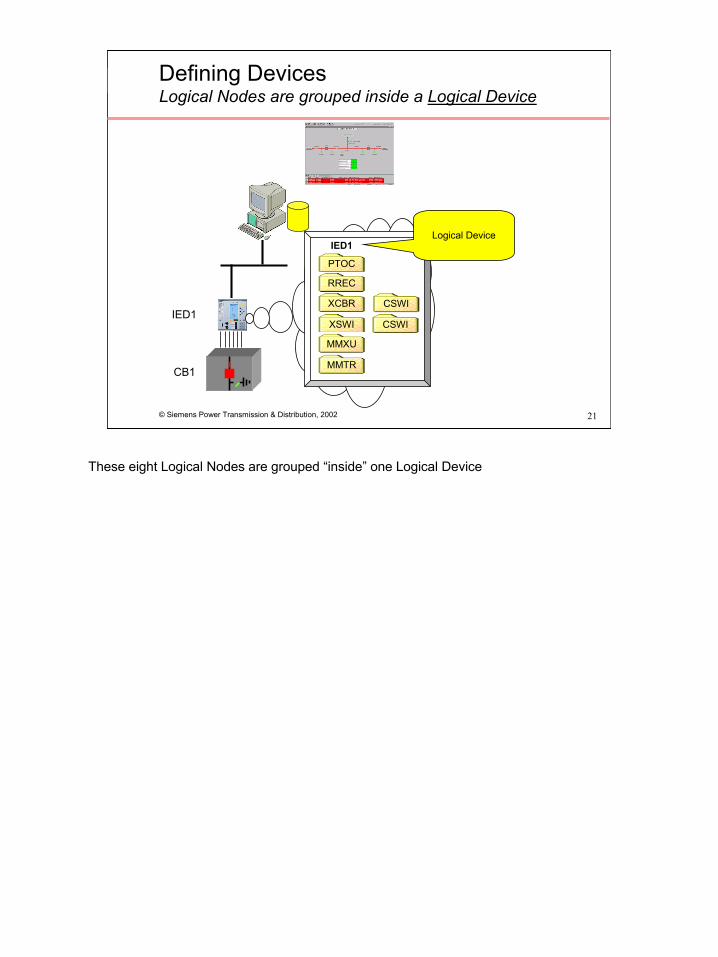
Defining DevicesLogical Nodes are grouped inside a Logical Device
CB1
IED1
PTOC
RREC
XCBR
XSWI
MMXU
MMTR
IED1Logical Device
CSWI
CSWI
These eight Logical Nodes are grouped “inside” one Logical Device

22
© Siemens Power Transmission & Distribution, 2002 22
Accessing DataThink Windows Explorer
PTOC (Time Over Current LN )RREC (Autorecloser LN )XCBR (Switchgear – Circuit Breaker)CSWI (Control - Circuit Breaker)XSWI (Switchgear – Disconnect)CSWI (Control - Disconnect)MMXU (Measurement Unit)MMTR (Metering)
+
+
+
+
+
+
IED1 IED1/XCBR
+
+
Accessing data in a 61850 network is analogous to accessing data across a conventional IT network using Windows Explorer, i.e. browse the network until the data source is located, then drill-down into the data source until the data is located.
Let’s assume personnel responsible for the HMI wish to animate a CB symbol on a one-line diagram:•CB1 is being controlled and monitored by IED1, so they would browse the network until this Logical Device was located•They would need enough 61850 nomenclature knowledge to know that the XCBR LN is associated with the status of the CB, then drill down into that “folder”
23
© Siemens Power Transmission & Distribution, 2002 23
Accessing DataTree view
Mode (Mode)Beh (Behavior )Health (Health)Name (Name plate)Loc (Local operation)EEHealth (External equipment)EEName (External equipment name plate)OperCnt (Operation counter)Pos (Switch position)BlkOpen (Block opening)BlkClos (Block closing)ChMotEna (Charger motor enabled)CBOpCap (Circuit breaker operating capability)POWCap (Point On Wave switching capability)
+
+
+
+
+
+
+
+
+
+
+
+
+
+
XCBR
PTOCRREC
+
+
-
IED1/XCBR.PosIED1
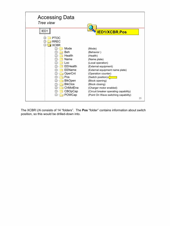
The XCBR LN consists of 14 “folders”. The Pos “folder” contains information about switch position, so this would be drilled-down into.

24
© Siemens Power Transmission & Distribution, 2002 24
Accessing DataTree view
Mode (Mode)Beh (Behavior )Health (Health)Name (Name plate)Loc (Local operation)EEHealth (External equipment)EEName (External equipment name plate)OperCnt (Operation counter)Pos (Switch position)
+
+
+
+
+
+
+
+
-
XCBR
PTOCRREC
+
+
-
ctlValstValpulseConfigoperTimq…more
intermediate-state (0)off (1)on (2)bad-state (3)
IED1/XCBR.Pos.stValIED1
The Pos “folder” is of type Controllable Double Point (CDP) data class. The CDP data class consists of 14 data fields (some are mandatory and must always be present, others are optional). The StVal field contains the value of the CB.

25
© Siemens Power Transmission & Distribution, 2002 25
Data Communication using 61850Data Context is retained
DN
P 3.
0 (to
EM
S/SC
ADA
IED 1 Data
“67 TOC Pick-up”
“CB1 is Closed”
“I Phase A is 200A”
“V Phase A is 26.3kV”IED1/XCBR.Pos.stVal (CB pos)
IED1/PTOC.Start.general (67 TOC PU)
IED1/MMXU.A.phsA.mag (Ia)
IED1/MMXU.V.phsA.mag (Va)
61850 Messages
HMI LinkageCB pos = IED1/XCBR.Pos.stVal
67 TOC PU = IED1/PTOC.Start.general
Ia = IED1/MMXU.A.phsA.mag
Vab = IED1/MMXU.V.phsA.mag
DB DW 1 = IED1/XCBR.Pos.stVal
DB DW 2 = IED1/PTOC.Start.general
DB DW 3 = IED1/MMXU.A.phsA.mag
DB DW 4 = IED1/MMXU.V.phsA.mag
61850 Driver into DB
CB1
IED1
In our earlier DNP example HMI personnel had to cross-reference data against protocol address information to know which data points to connect to which objects on the one-line. There was a commensurate increase in engineering effort and the possibility of error. In our 61850 example however, HMI personnel browse the devices directly and subscribe to the data they require – there is no need for an intermediate cross-reference of data.

26
© Siemens Power Transmission & Distribution, 2002 26
Data Communication using 61850Devices are self describing
CB1
IED1
CB2 CB3 CB4
IED2 IED3 IED4
CB Object
Vendor W
Vendor X
Vendor Y
Vendor Z
The remainder of the system is configured in the same fashion. Data from the other IEDs are available to the HMI and Substation Controller for incorporation into one-lines, historical archives, control sequences, logic programs, automation applications, etc.
27
© Siemens Power Transmission & Distribution, 2002 27
Things to Remember
61850 is UCA 2.0 plus…
Self description
1
2
Here’s the second of the three concept this presentation aims to convey(2) IEC 61850 supports self description
You can see what data a device has by communicating with it and browsing its contents.

28
© Siemens Power Transmission & Distribution, 2002 28
Data Communication using 61850Peer-to-peer communications are possible
CB1
IED1
CB2 CB3 CB4
IED2 IED3 IED4
GOOSE (Generic object oriented
system-wide events) Multicast Message
Vendor W
Vendor X
Vendor Y
Vendor Z
GOOSE is an acronym for Generic Object Orientated System-wide Events. It aims to replace the conventional hardwired logic necessary for intra-relay coordination with station-bus communications. Upon detecting an event, the IED(s) use a multi-cast transmission to notify those devices that have registered to receive the data. The performance requirements are stringent – no more than 4ms is allowed to elapse from the time an event occurs to the time of message transmission. The number of IEDs, the network topology and the type of event will all contribute to the amount of data that will be generated after an event. Collisions are quite possible in an Ethernet network in this scenario, so the GOOSE messages are re-transmitted multiple times by each IED. Three LAN configurations (10 MB switched hub, 100 MB shared hub, and 100 MB switched hub) are able to deliver 100 messages within 4 milliseconds.
29
© Siemens Power Transmission & Distribution, 2002 29
Data Communication using 61850Sharing configuration data
CB1
IED1
CB2 CB3 CB4
IED2 IED3 IED4
IED Data Set Definitions defined using XML
(vendor independence)
Proprietary configuration tool of vendor W
Vendor W
Vendor X
Vendor Y
Vendor Z
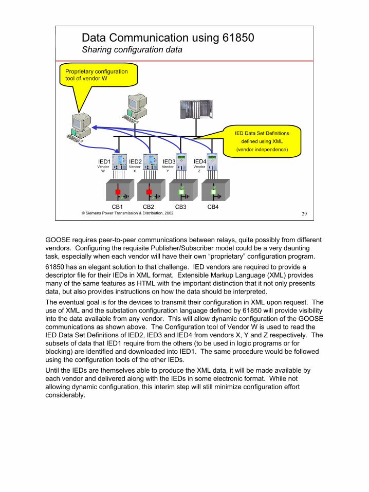
GOOSE requires peer-to-peer communications between relays, quite possibly from different vendors. Configuring the requisite Publisher/Subscriber model could be a very daunting task, especially when each vendor will have their own “proprietary” configuration program. 61850 has an elegant solution to that challenge. IED vendors are required to provide a descriptor file for their IEDs in XML format. Extensible Markup Language (XML) provides many of the same features as HTML with the important distinction that it not only presents data, but also provides instructions on how the data should be interpreted. The eventual goal is for the devices to transmit their configuration in XML upon request. The use of XML and the substation configuration language defined by 61850 will provide visibility into the data available from any vendor. This will allow dynamic configuration of the GOOSE communications as shown above. The Configuration tool of Vendor W is used to read the IED Data Set Definitions of IED2, IED3 and IED4 from vendors X, Y and Z respectively. The subsets of data that IED1 require from the others (to be used in logic programs or for blocking) are identified and downloaded into IED1. The same procedure would be followed using the configuration tools of the other IEDs.Until the IEDs are themselves able to produce the XML data, it will be made available by each vendor and delivered along with the IEDs in some electronic format. While not allowing dynamic configuration, this interim step will still minimize configuration effort considerably.
30
© Siemens Power Transmission & Distribution, 2002 30
Things to Remember
61850 is UCA 2.0 plus…
Self description
Client-Server and Peer-to-peer communications
1
2
3
And here’s the last of the three concept this presentation aims to convey(3) IEC 61850 supports both Client-Server and Peer-to-Peer communications. It is the peer-to-peer communications ability that is used to exchange GOOSE messages between IEDs.
31
© Siemens Power Transmission & Distribution, 2002 31
Station Bus vs Process Bus61850-8 vs 61850-9
Hardwired I/O
Station Bus
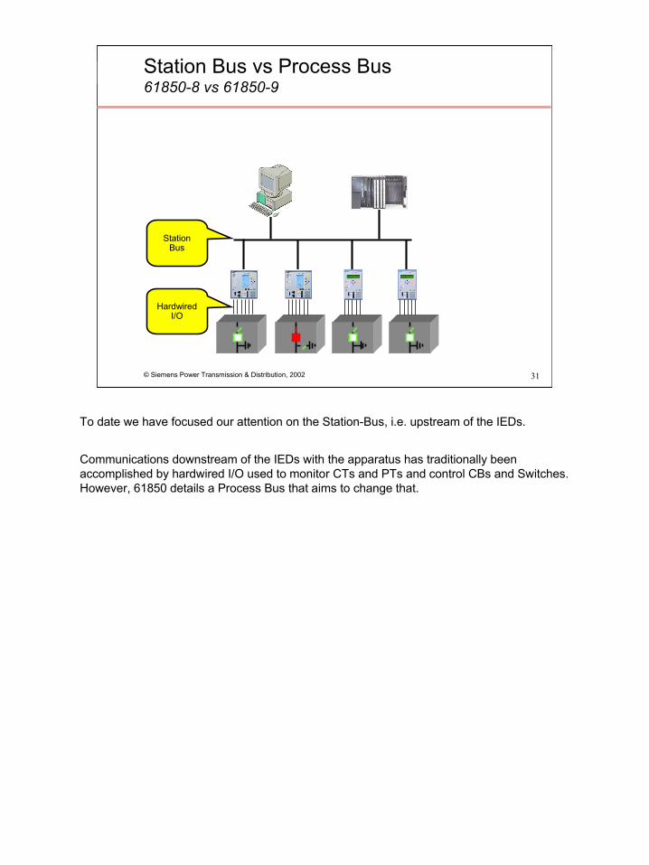
To date we have focused our attention on the Station-Bus, i.e. upstream of the IEDs.
Communications downstream of the IEDs with the apparatus has traditionally been accomplished by hardwired I/O used to monitor CTs and PTs and control CBs and Switches. However, 61850 details a Process Bus that aims to change that.

32
© Siemens Power Transmission & Distribution, 2002 32
Station Bus vs Process Bus61850-8 vs 61850-9
Station Bus
Process Bus
The Process Bus replaces hard wired connections with communication lines. “Smart” CTs, PTs and switchgear continuously transmit data over the process bus and any upstream devices that wish to use the data for protection, measurements, metering or monitoring do so by monitoring the communications.There are two flavors of 61850-9:9-1, Serial unidirectional multidrop point to point link9-2, IEEE 802.3 based process bus, i.e. Ethernet
Although still under development, process bus definitely appears viable. Siemens and ABB successfully demonstrated interoperability using a combination Substation and Process bus architecture in May 2001 at the Utility Substation Initiative meeting in Vancouver.
33
© Siemens Power Transmission & Distribution, 2002 33
Analog inputs
1. Simulated fault2. Trip generated
Goose Message: Trip
3. New position
Goose Message: Reclose
4. Reclose command5. New position
Goose Message: Positions
Goose Message: Positions
Relay
s
Switchgear Simu.
Test Equipment
Relay
Process BusEthernet
ProtectionFunction
AutorecloserFunction
Example of 61850 InteroperabilityDemonstrated in Vancouver, May 2001
XMLFile
0. Configuration
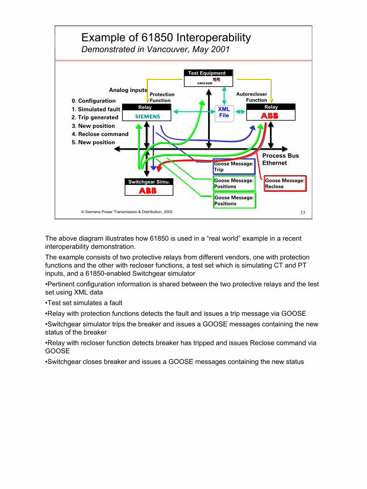
The above diagram illustrates how 61850 is used in a “real world” example in a recent interoperability demonstration.The example consists of two protective relays from different vendors, one with protection functions and the other with recloser functions, a test set which is simulating CT and PT inputs, and a 61850-enabled Switchgear simulator•Pertinent configuration information is shared between the two protective relays and the test set using XML data•Test set simulates a fault•Relay with protection functions detects the fault and issues a trip message via GOOSE•Switchgear simulator trips the breaker and issues a GOOSE messages containing the new status of the breaker•Relay with recloser function detects breaker has tripped and issues Reclose command via GOOSE•Switchgear closes breaker and issues a GOOSE messages containing the new status
34
© Siemens Power Transmission & Distribution, 2002 34
61850 is UCA 2.0 plus…
• Different terminology (Logical Nodes vs Bricks)• Expanded GOOSE• Different control model• Process bus• Conformance test defined• General device requirements defined• Communications requirements defined• XML-based Engineering Language
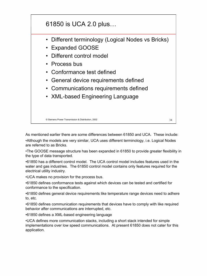
As mentioned earlier there are some differences between 61850 and UCA. These include:•Although the models are very similar, UCA uses different terminology, i.e. Logical Nodes are referred to as Bricks.•The GOOSE message structure has been expanded in 61850 to provide greater flexibility in the type of data transported.•61850 has a different control model. The UCA control model includes features used in the water and gas industries. The 61850 control model contains only features required for the electrical utility industry. •UCA makes no provision for the process bus.•61850 defines conformance tests against which devices can be tested and certified for conformance to the specification.•61850 defines general device requirements like temperature range devices need to adhere to, etc.•61850 defines communication requirements that devices have to comply with like required behavior after communications are interrupted, etc.•61850 defines a XML-based engineering language •UCA defines more communication stacks, including a short stack intended for simple implementations over low speed communications. At present 61850 does not cater for this application.
35
© Siemens Power Transmission & Distribution, 2002 35
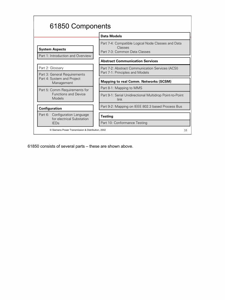
Part 10: Conformance Testing
Configuration
Mapping to real Comm. Networks (SCSM)
Part 1: Introduction and Overview
Part 7-4: Compatible Logical Node Classes and Data Classes
Part 7-3: Common Data Classes
Part 7-2: Abstract Communication Services (ACSI)Part 7-1: Principles and Models
System Aspects
Part 2: Glossary
Part 3: General RequirementsPart 4: System and Project
Management
Part 5: Comm Requirements for Functions and Device Models
Part 8-1: Mapping to MMS
Part 9-1: Serial Unidirectional Multidrop Point-to-Point link
Part 9-2: Mapping on IEEE 802.3 based Process Bus
Abstract Communication Services
Data Models
TestingPart 6: Configuration Language for electrical Substation IEDs
61850 Components
61850 consists of several parts – these are shown above.

36
© Siemens Power Transmission & Distribution, 2002 36
Useful Links
http://www.ucausersgroup.org/IEC61850docs.htmhttp://www.nettedautomation.com/index.html
37
© Siemens Power Transmission & Distribution, 2002 37
Questions?