ultimaker preface this is the installation manual for the extrusion upgrade of your ultimaker. the...
TRANSCRIPT
INSTALLATION MANUALOriginal manual V1.0 2016
UltimakerEXTRUSION UPGRADE

DISCLAIMER
Please read and understand the contents of this installation manual. Failure to read the manual may lead to
personal injury, inferior results or damage to the Ultimaker. Always ensure that anyone who installs the
upgrade knows and understands the contents of the manual.
We can not control the conditions in which you install the upgrade. For this and other reasons, we do not assume
responsibility and expressly disclaim liability for loss, injuries, damage, or expense arising out of or in any way
connected with the assembly, handling, storage, use or disposal of the product.
The information in this document was obtained from sources which we believe are reliable. However, the information is
provided without any warranty, express or implied, regarding its correctness.
Copyright © 2016 Ultimaker. All rights reserved worldwide.
This language version of the manual is verified by the manufacturer (Original manual). No part of this publication, including pictures may be
reproduced and/or made public, whether by printing, photocopying, microfilm or by any other means whatsoever, without the prior written
permission of Ultimaker.
3
1. INTRODUCTION ..................................................................................................................................................................................... 5
Your upgrade kit 6
2. DISASSEMBLING AND ASSEMBLING ............................................................................................................................................ 8
The electronics - disassembling 9
Feeder and feeder motor 13
Build plate clamps 14
Print head 15
The electronics - assembling 17
3. ALIGNING THE AXLES ....................................................................................................................................................................... 19
4. COMPLETING THE UPGRADE ....................................................................................................................................................... 22
Updating firmware 23
Bed levelling 24
The finishing touch 26
TABLE OF CONTENTS

4
PREFACE
This is the installation manual for the Extrusion Upgrade of your Ultimaker.
The manual guides you through the steps to successfully install the upgrade of the feeder and print head.
Please read all information and follow the instructions and guidelines in this manual carefully. This ensures that possible
accidents and injuries will be prevented and that you will obtain great quality prints.
Every effort has been made to make this manual as accurate and complete as possible. The information is believed to
be correct but does not purport to be all inclusive and shall be used only as a guide. Should you discover any errors
or omissions, please bring this to our attention, so that we can make amendments. This will enable us to improve our
documentation and service to you.

5
INTRODUCTION
Your upgrade kit consists of several parts. This chapter describes the components
that are part of the upgrade kit.
1

6
YOUR UPGRADE KIT
1 Pre-assembled print head
2 Nozzle kit
3 Short spool holder
4 Print head shafts (X and Y)
5 Hex wrench 2 mm
6 Pre-assembled feeder
7 Calibration card
8 Build plate clamps (2x)
9 Geared feeder mounting plate
10 M3 ring (2x)
11 M3 x 10 mm screw (6x)
12 “+” stickers
13 Print head alignment tool (2x)
14 Print head axis (dis)assemble tool (2x)
15 Feeder motor
16 Grease
Check if all these parts are included before continuing. If not, contact your local reseller.
Additional tools needed:
• Flat 1.5 mm screwdriver
• Socket wrench 5.5 mm or pliers for the lock nuts
13
1211
8
6
4
516
3
15
2
1 9
10
7
14

7
DISASSEMBLING AND ASSEMBLING
To install your upgrade, you must first disassemble the electronics, old feeder,
feeder motor, build plate clamps and print head. This chapter describes how to
disassemble and assemble the parts and how to reconnect the electronics.
2
8
THE ELECTRONICS
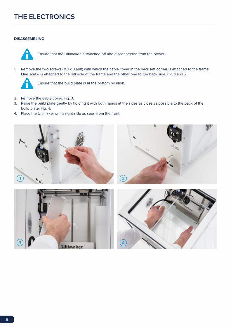
DISASSEMBLING
Ensure that the Ultimaker is switched off and disconnected from the power.
1. Remove the two screws (M3 x 8 mm) with which the cable cover in the back left corner is attached to the frame.
One screw is attached to the left side of the frame and the other one to the back side. Fig. 1 and 2.
Ensure that the build plate is at the bottom position.
2. Remove the cable cover. Fig. 3.
3. Raise the build plate gently by holding it with both hands at the sides as close as possible to the back of the
build plate. Fig. 4.
4. Place the Ultimaker on its right side as seen from the front.
3 4
21

9
5. Remove the two screws (M3 x 12 mm) and locknuts from the electronics cover and set them aside. Use a socket
wrench or pliers to hold the locknut, while unscrewing the screws from the inside. Fig. 5 and 6.
6. Remove the cover and place it aside. Fig. 7.
7. Remove the four screws (M3 x 25 mm) from the main board and set the screws and spacers aside.
Fig. 8 and 9.
5
7 8
9
6

10
8. Take the main board carefully.
Ensure that the wires are still connected when you hold the main board.
9. Remove the wires from the green terminal HEATER 1 by pressing the top of the terminal with the flat screwdriver.
Fig. 11.
If you have an older model of the main board on your Ultimaker, you need to loosen the screws instead of
pressing to remove the wires. Fig. 12.
10. Disconnect the hot end fan from the middle of the board. Fig. 13.
11. Disconnect the feeder motor from E1 on the main board. Fig. 14.
12
13 14
11

11
12. There’s a ferrite core around the motor cables. Open it so you can remove the feeder motor wire completely. (It’s
possible that your Ultimaker is older and doesn’t have the ferrite core). Fig. 15.
Do not pull on the wires.
Always pull on the plugs.
13. Disconnect the PT100 sensor from TEMP1 on the main board. Fig. 16.
14. Disconnect the print head fans from FAN PWM on the main board. Fig. 17.
Do not pull on the wires.
Always pull on the plugs.
15. Pull the braided sleeve with cables and the feeder motor wire out through the hole in the bottom left corner and the
hole in the back plate. Fig. 18.
16. Place the Ultimaker back upright and move the build plate down for easier access during the next steps.
When placing the machine upright, take care of where your main board is, so you do not break it.
The main board is reinstalled after you replace the feeder, feeder motor and print head.
15 16
17 18

12
FEEDER AND FEEDER MOTOR
DISASSEMBLING
1. Remove the four screws (M3 x 25 mm) from the feeder. While removing the screws, hold the feeder motor at the
inside of the machine to prevent the motor from falling down. Fig. 19.
2. Keep the screws and washers and set the feeder and motor aside. You do not need the feeder and feeder motor
anymore.
ASSEMBLING
1. Take the new feeder motor and apply some grease (Magnalube) to the small gear. Make sure the entire gear is
covered with a thin layer of grease. Fig. 20.
2. Place the feeder motor with the wires down on the inside of your Ultimaker and place the geared feeder mounting
plate with the hole at the bottom over the four screw holes on the outside.
Do not trap any of the wires next to the feeder motor.
Ensure that the wires run between the motor and the frame.
3. Attach the feeder motor to the body with the feeder mounting plate, using the four new screws (M3 x 10 mm) and
the washers from the old feeder. Fig. 21.
4. Place the feeder on the back with the small lever on the bottom and use the two supplied screws (M3 x 10 mm) with
M3 rings around it to attach it. Fig. 22.
19
21
20
22
13
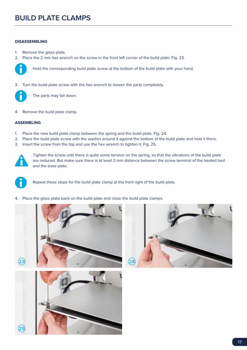
DISASSEMBLING
1. Remove the glass plate.
2. Place the 2 mm hex wrench on the screw in the front left corner of the build plate. Fig. 23.
Hold the corresponding build plate screw at the bottom of the build plate with your hand.
3. Turn the build plate screw with the hex wrench to loosen the parts completely.
The parts may fall down.
4. Remove the build plate clamp.
ASSEMBLING
1. Place the new build plate clamp between the spring and the build plate. Fig. 24.
2. Place the build plate screw with the washer around it against the bottom of the build plate and hold it there.
3. Insert the screw from the top and use the hex wrench to tighten it. Fig. 25.
Tighten the screw until there is quite some tension on the spring, so that the vibrations of the build plate
are reduced. But make sure there is at least 2 mm distance between the screw terminal of the heated bed
and the base plate.
Repeat these steps for the build plate clamp at the front right of the build plate.
4. Place the glass plate back on the build plate and close the build plate clamps.
BUILD PLATE CLAMPS
23
25
24

14
DISASSEMBLING
1. Slide a print head axis (dis)assemble tool on either side of the left sliding block until it clicks into the axle. Fig. 26.
2. Pop up the print head shaft until it comes out of the sliding block at this side. Fig. 27.
3. Do the same on the right side.
4. Repeat the steps 2 and 3 on the front and back, using the print head axis (dis)assemble tools upside down. Fig. 28
and 29.
5. Turn all sliding blocks away from the print head. Fig. 30.
Turn the sliding blocks away from the top and always act gently.
6. Move the print head so the shafts move out of the sliding blocks and lift upwards. Set the print head aside, you do
not need anymore. Fig. 31.
26
28
30
27
29
31
PRINT HEAD

15
ASSEMBLING
1. Guide the two new print head axles through the new print head. Fig. 32.
The long axle is the X-axle and the short axle is the Y-axle.
2. Place the print head in its original position and ensure that each axle is between the belts. Fig. 33.
The X-axle runs from left to right and the Y-axle runs from front to back.
3. Align the axles to each sliding block. Fig 34.
4. Place the print head axis (dis)assemble tools on either side of the sliding blocks.
5. Click the X-axle in the left sliding block and push down until it snaps into place. Fig. 35.
Support the sliding block as much as possible when you snap the axle into place.
Ensure that the axles are put in centrally with equal space on each side and that there is at least 1 mm
distance between the axle and the frame. Double-check that the left side of X-axle is activating the
Y limit switch.
32
34
33
35

16
Repeat the steps for the other side of the X-axle and the front and back of the Y-axle. Fig. 36 and 37.
Ensure that all sliding blocks are upright.
6. Connect the end of the bowden tube to the feeder. Fig. 38.
7. Place the clamp clip around the tube coupling collet to secure the bowden tube. FIg. 39.
36
38
37
39

17
ASSEMBLING
1. Place the Ultimaker on its right side.
2. Feed the braided sleeve through the hole at the back and the hole at the bottom. Fig. 40.
Ensure that the whole braided sleeve is through the hole, as it was before you took it out.
3. Connect the blue-orange wire to the hot end fan connector on the middle of the board. Fig. 41.
4. Connect the PT100 sensor to TEMP1 on the main board. Fig. 42.
5. Connect the yellow-green wire to the Fan PWM. Fig. 43.
6. Connect the feeder motor to E1. Fig. 44.
7. Guide the motor wires of the Y motor and feeder motor through the ferrite core and close the ferrite core. Fig. 45.
THE ELECTRONICS
40
42
44
41
43
45

18
8. Connect the wires of the heater cartridge to the green terminal HEATER 1. Press at the top of the terminal with
the flat screwdriver and insert the wires. Fig. 46.
If you have an older model of the electronics on your Ultimaker, you need to tighten the screws instead of
pressing to connect the wires.
Gently pull at the heater wires to ensure they are stuck in place.
9. Put the main board back in place and secure it with the four screws (M3 x 25 mm) and spacers you set aside when
disassembling the electronics. Fig. 47 and 48.
The screws must be inserted from the inside of the Ultimaker. The spacers must be between the bottom plate
of the machine and the main board.
Be careful that no wires are trapped between the main board and frame. Push towards the back panel before
completely tightening the screws.
10. Place the electronics cover back and secure it with the two screws (M3 x 12 mm) and locknuts you set aside when
disassembling the electronics. Fig. 49.
46
48
47
49
19
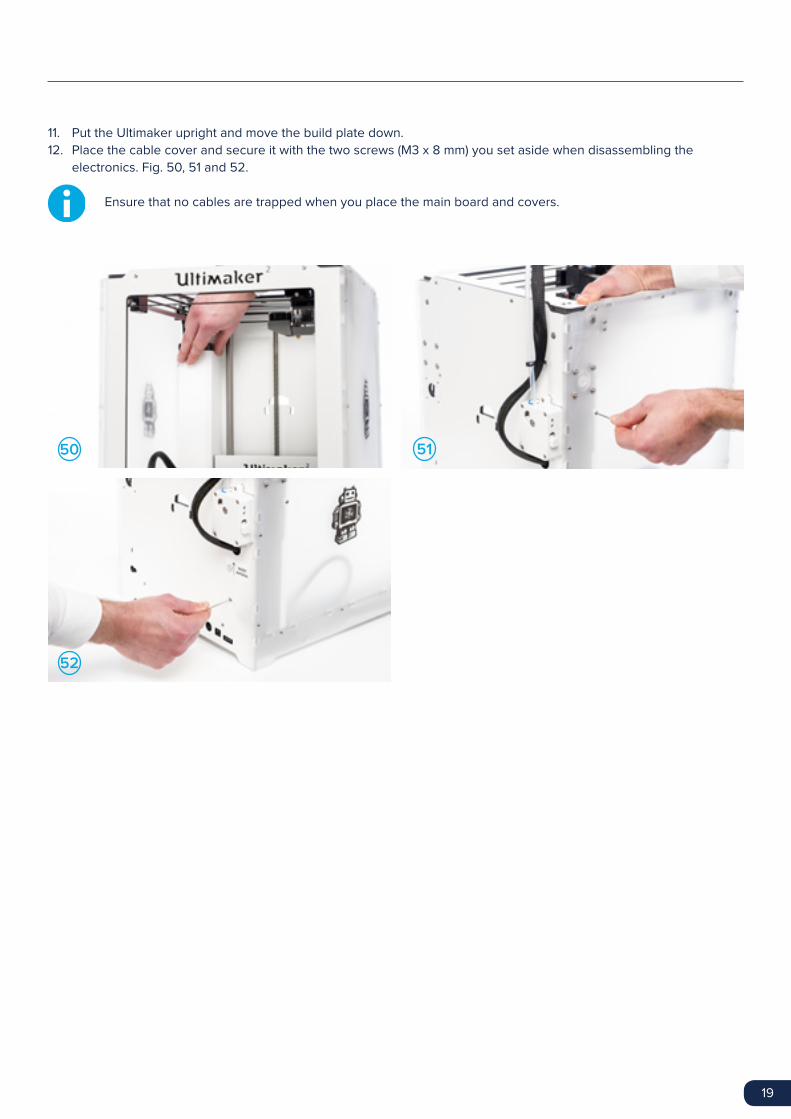
11. Put the Ultimaker upright and move the build plate down.
12. Place the cable cover and secure it with the two screws (M3 x 8 mm) you set aside when disassembling the
electronics. Fig. 50, 51 and 52.
Ensure that no cables are trapped when you place the main board and covers.
50
52
51

20
ALIGNING THE AXLES
To ensure that your prints are perfect after the upgrade you need to align the axles.
This chapter describes how to do this.
3
21
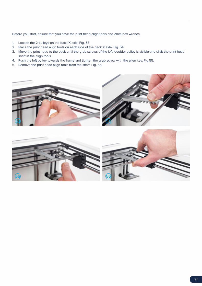
Before you start, ensure that you have the print head align tools and 2mm hex wrench.
1. Loosen the 2 pulleys on the back X axle. Fig. 53.
2. Place the print head align tools on each side of the back X axle. Fig. 54.
3. Move the print head to the back until the grub screws of the left (double) pulley is visible and click the print head
shaft in the align tools.
4. Push the left pulley towards the frame and tighten the grub screw with the allen key. Fig 55.
5. Remove the print head align tools from the shaft. Fig. 56.
53
55
54
56
22
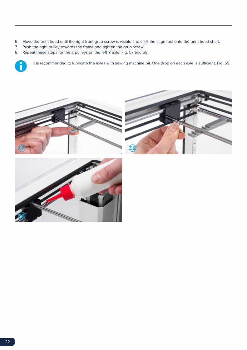
6. Move the print head until the right front grub screw is visible and click the align tool onto the print head shaft.
7. Push the right pulley towards the frame and tighten the grub screw.
8. Repeat these steps for the 2 pulleys on the left Y axle. Fig. 57 and 58.
It is recommended to lubricate the axles with sewing machine oil. One drop on each axle is sufficient. Fig. 59.
57
59
58

23
COMPLETING THE UPGRADE
You need to perform two last steps to complete the upgrade and prepare the
Ultimaker for printing.
4

24
UPDATING FIRMWARE
To print the first print with the new parts in your Ultimaker, you need to update your firmware.
1. Connect the Ultimaker to your computer with the USB cable.
2. Connect the power supply and turn on the Ultimaker.
3. Start Cura and select the Ultimaker 2+ or Ultimaker 2 Extended+ in the “Machine” menu (depending on which
Ultimaker you have).
4. Go to “Machine” > “Install default firmware” Cura will now automatically upload the correct firmware to your
Ultimaker.
Not updating your firmware might cause permanent damage to your machine.

25
After working on your Ultimaker, you must re-level the build plate to ensure your 3D prints stick
well to the build plate. To level the build plate:
1. Go to “Maintenance” > “Build plate” to start the bed leveling process.
2. Wait for the Ultimaker to do its homing procedure and continue when the print head is in the center at the back of
the build plate.
3. Rotate the button at the front until there is approximately 1 mm distance between the nozzle and the build plate.
Make sure that the nozzle is close to the build plate without touching it.
4. Adjust the front left and front right build plate screw to roughly level the build plate at the front side. Again there
should be a distance of approximately 1 mm between the nozzle and build plate.
5. Place the calibration card in between the nozzle and build plate.
6. Adjust the build plate screws on the front left side, front right side and the middle of the back until you feel slight
friction when moving the card.
7. Press “Continue”. The print head moves to the second point.
8. Repeat step 4 and step 5.
9. Press “Continue” again. The print head moves to the third point.
10. Repeat step 4 and step 5.
Do not push on the build plate while fine-tuning with the calibration card. This will lead to inaccuracies.
BED LEVELLING

26
THE FINISHING TOUCH
Now the work is done, it’s time to seal your upgrade with the two small + stickers.
Stick the biggest + sticker behind the name of your Ultimaker on the front panel and the smallest on the back plate
cover. It is the subtle finishing touch that shows that your Ultimaker is upgraded with latest parts and is ready for making
prints of the highest quality.

www.ultimaker.com