umv 3301 - leroy-somer · int. power supp. 5 4/20ma loss 21 processor 6 alarm 1 active 22 encoder 7...
TRANSCRIPT

UMV 3301Open or closed loopflux vector controllerInstallation and maintenance
Réf. 2416 GB - 4.33 / d - 01.01
This manual must be given
to the end user
0
1
0
1
0
1
term.
0
1
0
1
Jogginselectio
02.30
02.43
Speedreference
image
02.16
02.33
Speedref.
FasterSlower
Faster/slowerfunction

1 - General informationRTU transmission modeMessage frames sent in RTU transmission mode do notinclude header nor frame-end character. Frame synchro-nization can be done by simulating a synchronous mes-sage : the receiving device monitors the elapsed timebetween receipt of two consecutive characters. If threeand one-half character times elapse without a new cha-racter or completion of the frame, then the receiving de-vice assumes that the next byte received will be the firstof a new frame. The partly-received frame is said physi-cally mistaken. It does not get any response and it isflushed by the next received frame. In RTU mode trans-mission, each byte is coded in hexadecimal system (00to FF).A control key is included in the frames. It is made of twobytes, issued from the evaluation of a CRC16 (CyclicRedundancy Check 16 bits) using the polynom x^16 + x^15 + x^2 + 1 and applied on all the frame ex-cept the control field. The 2 bytes are sent low byte first.The RTU coding system is mainly used for MODBUSnetwork applications, especially because of the high-transmission-error recovery due to CRC16.
2 - Protocol framesa) Slave reading frame requested by the master
b) Slave reading frame responded by the slave
c) Slave writing frame requested the master
d) Slave writing frame responded by the slave
3 - Commands (from UMV 3301 Software ver-sion V625 and above)- run forward command : parameter N2102 set to 2,- run reverse command : parameter N2102 set to 3,- stop-reset command : parameter N2102 set to 1.
1
UMV 3301MODBUS
Slave numberOrder (03)
1st word's addressnumber of words
CRC 16
1 bytehexadecimal
2 byteshexadecimal
CRC 16
Slave numberOrder (03)
Number of bytesWord 1
Word 2Word n
1 bytehexadecimal
2 byteshexadecimal
Slave number
1st word's addressNumber of words
CRC 16
1 bytehexadecimal
2 byteshexadecimal
Order (10h)
1st word's addressNumber of words
CRC 16
Number of bytesWord 1
Word 2Word n
Slave numberOrder (10h)
1 bytehexadecimal
1 bytehexadecimal
2 byteshexadecimal
2 byteshexadecimal
4 - Parameters- All parameters in publication N° 2416-4.33.- Errors status : N1801.
CAUTION : Do not forget to set parameter N0601 as command origin and parameter N1001 as reset origin.
5 - Address calcultationWords are addressed corresponding to parameters address : address = MM x 256 + PP (where MM stands for Menu and PP forparameter).e.g. : address = 01 x 256 + 23 for parameter 00 11 .. 22 33.
Display N1801 Display N1801BUS OVERVOLTAGE 0 BUS Underv. 16OVERCURRENT 1 MOTOR Th. 17I IMBALANCE * 2 MOTOR PTC PROBE 18CONTROLLER Th. 3 RS 485 LINK 19RESISTOR Th. 4 CDC-UMV 20Int. POWER supp. 5 4/20mA LOSS 21PROCESSOR 6 ALARM 1 ACTIVE 22ENCODER 7 ALARM 2 ACTIVE 23ENCODER LOSS 8 ALARM 3 ACTIVE 24PROCESSOR opt 1 9 ALARM 4 ACTIVE 25PROCESSOR opt 2 10 OVERSPEED 26EXTERNAL 11 I LIMIT TIME 27MAINS FAILURE 12 IGBT 29PHASE MISSING 13 DIRECTION / ROT 30MAINS Underv. 14 MOTOR PHASE 31MAINS Overv. 15 No Assigment 32* from rating 180T and above
ADDENDUMto manual for UMV 3301 réf. 2416c

2
UMV 3301 open or closed loopflux vector controller
NOTE
LEROY-SOMER reserves the right to modify its product characteristics at any time to incorporate the latest technologi-cal developments. The information contained in this document may therefore be changed without prior warning.
LEROY-SOMER gives no contractual guarantee whatsoever concerning the information published in this document andcannot be held responsible for any errors it may contain, nor for any damage arising from its use.
CAUTION
For the user’s own safety, this variable speed drive must be connected to an approved earth ( terminal).
If accidentally starting the installation is likely to cause a risk to personnel or the machines being driven, it is essential to supplythe device via a circuit-breaking device (power contactor) which can be controlled via an external safety system (emergencystop, detection of errors on the installation).
The variable speed drive is fitted with safety devices which, in the event of a fault, control stopping and thus stop the motor. Themotor itself can become jammed for mechanical reasons. Voltage fluctuations, and in particular power cuts, may also cause themotor to stop.The removal of the causes of the shutdown can lead to restarting, which may be dangerous for certain machines or installations.In such cases, it is essential that the user takes appropriate precautions against the motor restarting after an unscheduled stop.
The variable speed drive is designed to be able to supply a motor and the driven machine above its rated speed.If the motor or the machine are not mechanically designed to withstand such speeds, the user may be exposed to seriousdanger resulting from their mechanical deterioration.It is important that the user checks that the installation can withstand it before programming a high speed.
The variable speed drive which is the subject of this manual is designed to be integrated in an installation or an electricalmachine, and can under no circumstances be considered to be a safety device. It is therefore the responsibility of the machinemanufacturer, the designer of the installation or the user to take all necessary precautions to ensure that the system complieswith current standards, and to provide any devices required to ensure the safety of equipment and personnel.
Using the speed controller for lifting : if this application is selected, special instructions, available on request, must be observed.The user is responsible for obtaining this instruction manual from his usual LEROY-SOMER contact.
LEROY-SOMER declines all responsibility in the event of the above recommendations not being observed.
........................................
Manual corresponding to software version 9.02
Update of manual 2416 - 4.33/c - 06.00
For more recent software versions, consult the attached guide or LEROY-SOMER

Throughout the manual, this symbol warns against consequences which may arise from inappropriate use of the speed controller, since electrical risks may lead to material and physical damage as well as constituting a fire hazard.
1 - GeneralAccording to their degree of protection, speed controllerscan comprise live bare parts, either moving or turning, aswell as hot surfaces during operation.Unjustified removal of protections, incorrect use, faultyinstallation or inappropriate operation could represent aserious risk to personnel and machinery.For additional information, consult the manual.Work relating to transportation, installation, commissio-ning and maintenance must be carried out by experien-ced qualified personnel (see IEC 364 or CENELEC HD384, or DIN VDE 0100 and national specifications forinstallation and accident prevention).In these basic safety instructions, qualified personneldenotes persons competent in installation, mounting,commissioning and operation of a product and posses-sing the relevant qualifications.
2 - UseSpeed controllers are components designed for integration in installations or electrical machines.When integrated in a machine, commissioning must nottake place until the machine's conformity with the89/392/EEC Directive (Machinery Directive) has beenverified. The EN 60024 standard, stipulating notably thatelectrical actuators (which include speed controllers)cannot be regarded as circuit-breaking devices and cer-tainly not as operating devices, must be respected.Commissioning can only take place if the requirementsof the Directive on electromagnetic compatibility(89/336/EEC, modified by 92/31/EEC) are adhered to.Speed controllers fulfil the requirements of the73/23/EEC Low Voltage Directive, modified by93/68/EEC. The harmonized standards of the VDE 0160DIN series in connection with standard VDE 0660, part500 and EN 60146/VDE 0558 are also applicable.The technical characteristics and instructions concerningconnection conditions specified on the nameplate and inthe documentation supplied must be observed withoutfail.
3 - Transportation, storageAll instructions concerning transportation, storage andhandling must be respected.The climatic conditions specified in the technical manualmust be adhered to.
4 - InstallationThe installation and cooling of equipment must complywith the specifications stated in the manual supplied withthe product.Speed controllers must be protected against anyexcessive stress. In particular, avoid any damage toparts and/or modification of component isolating distan-ces during transportation and handling. Avoid touchingthe electronic components and contact parts.Speed controllers comprise parts which are sensitive toelectrostatic stress and can be easily damaged ifhandled incorrectly. Electrical components must not beexposed to mechanical damage or destruction (risks tohealth !).
5 - Electrical connectionWhen work is carried out on the powered-up speedcontroller, national accident prevention specificationsmust be respected.Electrical installation must conform with the appropriatespecifications (for example conductor cross-sections,protection via circuit-breaker fuses, connection ofprotective conductor). Refer to the documentation formore detailed information.Instructions for an installation complying withelectromagnetic compatibility requirements such asscreening, earthing, presence of filters and correctinsertion of cables and conductors) are outlined in thedocumentation supplied with the speed controller. Theseindications must be respected in all cases, even if thespeed controller has the CE mark. Adherence to thelimits imposed by EMC legislation relieves theinstallation or machine manufacturer of responsibility.
6 - OperationInstallations incorporating speed controllers must beequipped with additional protection and monitoringdevices as set down in the relevant current safetyregulations : law on technical equipment, accidentprevention specifications, etc. Modifications to speedcontrollers using control software are permitted. After the speed controller is powered down, active partsof the equipment and live connections must not betouched immediately, as the capacitors may still becharged. In view of this, heed the warnings fixed to thespeed controllers.During operation, all doors and protective devices mustremain closed.
7 - Care and maintenanceRefer to the manufacturer's documentation.
This document must be supplied to the end user.
3
UMV 3301 open or closed loopflux vector controller
SAFETY AND OPERATING INSTRUCTIONS FOR THE SPEED CONTROLLER (Conforming to the low voltage directive 73/23/EEC, modified by 93/68/EEC)

PREFACEThis manual describes how to commission UMV 3301 flux vector control electronic speed drives with digital techno-logy. It details all procedures to be carried out on the speed controller.
4
UMV 3301 open or closed loopflux vector controller
parallel shaft
helical bevel
Radialforced
ventilation
COMPABLOC 2000
ORTHOBLOC 2000
Induction motors
Gearboxes
UMV 3301 Speed controllers
RFI filter options
Control
Integrated card options Serial link (integrated)
planetary
PLANIBLOC 2000
RF
+ integrated T - UMV
FLT - 3359 HV
Motor choke options
CDC - UMV console (removable)
4-quadrant option
Brake
Forced ventilation
Encoder
Options
C O N F I G U R A T I O NRE N A I N E M E N T 0 1T
Mem
RUN
PAR
MODE
STOPRESET
RUN + = Marche avant - Forward
RUN + = Marche arrière - Reverse
CDC - UMV
SELF - MC

5
UMV 3301 open or closed loopflux vector controller
CONTENTS
Pages
1 - GENERAL INFORMATION1.1 - General operating principle.................................................................................... 61.2 - Product designation............................................................................................... 61.3 - Characteristics....................................................................................................... 6 to 131.4 - Environmental characteristics................................................................................ 131.5 - Weight and dimensions.......................................................................................... 14
2 - INSTALLATION2.1 - Checks on receipt.................................................................................................. 152.2 - Handling................................................................................................................. 152.3 - Installation precautions.......................................................................................... 152.4 - Installing the speed controller................................................................................ 162.5 - Remote installation of the CDC-UMV console....................................................... 16
3 - CONNECTIONS3.1 - Motor connection................................................................................................... 173.2 - Connecting the controller....................................................................................... 18 to 223.3 - Electrical and electromagnetic phenomena........................................................... 23 to 263.4 - Protection............................................................................................................... 28 - 293.5 - Wiring diagram....................................................................................................... 30
4 - COMMISSIONING4.1 - Using the CDC - UMV console.............................................................................. 31 to 354.2 - Simplified setup...................................................................................................... 364.3 - Menu 01 : Drive system configuration.................................................................... 37 to 394.4 - User menu............................................................................................................. 41 to 454.5 - Other menus.......................................................................................................... 47 to 125
5 - FAULTS - DIAGNOSTICS5.1 - General.................................................................................................................. 1265.2 - Fault indication....................................................................................................... 126 - 127
6 - MAINTENANCE6.1 - Introduction and advice.......................................................................................... 1286.2 - Care....................................................................................................................... 1286.3 - Measuring voltage, current and power................................................................... 1286.4 - Spare parts list....................................................................................................... 130 to 134
7 - OPERATING EXTENSIONS7.1 - Braking modules.................................................................................................... 1357.2 - Braking resistors (RF)............................................................................................ 1357.3 - RFI filters................................................................................................................ 136 - 1377.4 - SELF - MC chokes................................................................................................. 1377.5 - Forced ventilation kit.............................................................................................. 1377.6 - Connection option.................................................................................................. 1377.7 - PEGASE parameter-setting software.................................................................... 137
8 - SUMMARY OF SETTINGS............................................................................................ 139 to 147

1 - GENERAL INFORMATION
1.1 - General operating principleThe UMV 3301 is an A.C. open or closed loop flux vectorcontroller.The use of vector control with an induction motorenables the magnetizing current and active current tobe handled separately. The torque and speed of theinduction motor are controlled impeccably.The UMV 3301 flux vector controller uses an inverterbridge with IGBT transistors.This precision technology considerably diminishes thenoise and temperature rise of variable speed inductionmotors.The performance of the UMV 3301 is ideally suited touse in all 4 quadrants of the torque - speed relationship.
Diagram
During periods of operation in generator mode, theenergy restored by the motor is dissipated by resistors.
In certain applications where the energy restoration iscontinuous, the energy can be reinjected into anothermotor speed drive assembly.
Main characteristics :- power range : 55 kW to 600 kW,- speed range from 0 to 8000 min-1 (4 P motor),- operation at nominal torque from 0 to 1500 min-1 (4 Pmotor),- with speed feedback, nominal torque at zero speedmaintained permanently,- IP 55 motor,- master slave operation,- speed or torque pilot control.
6
UMV 3301 open or closed loopflux vector controller
M3
Calcul.
P.I.D.
Productionof 3
references
Powerbridge
Mains
PWM
Speedoutputwithout
feedback
Speedoutputwith
feedback
PID
PID
Speedreference
Magnet. Ireference
I cos ϕ
I sin ϕ
Currentcalculation
Torqueref.
Speedloop
Selection
Encoder
Torqueloop
Reactiveloop
DCBus
Motorparameters
1.2 - Product designationUMV 3301 : open or closed loop flux vector controller.120 = Rating in kVA.T = 3-phase supply 400V, TH = 3-phase supply 690VThis designation appears on the name plates located on the front panel and right side of the speed controller.
1.3 - Characteristics1.3.1 - Main electrical characteristics
MOTEURS LEROY-SOMER16015 ANGOULEME FRANCE
ENTREE - INPUT
TYPE : UMV 3301 120T
S/N :
Ph
Alim - électronique 280VA230/400/460V 50/60Hz
V (V) Hz (Hz) I (A) KVA3 400/460 50/60 207/197 143/157
Power supply3-phase supply 380V to 460V, ± 10 %, 50 Hz or 60 Hz, ± 2 % (75T to 600T)3-phase supply 525V to 690V , ± 10 %, 50Hz or 60Hz, ± 2 % (75TH to 700TH)
Electronic system supply
Single phase supply 230V, 400V or 460V, ± 10 %, 50/60Hz (75T to 600T)230V, 500V, 600V or 690V, ± 15 %, 50/60Hz (75TH to 700TH)300VA (75T to 265T and 75TH to 340TH)800VA (270T to 600T and 400TH to 700TH)
Output voltage From 0V of the power supplyMaximum number of power-ups per hour 20

7
UMV 3301open or closed loopflux vector controller
1.3.2 - Electrical output characteristics
High overtorque : for machines with strong resistive torque, for example : presses, grinders, extruding machines, conveyors, sieves, lifting or applications requiring rapid acceleration of high inertia.Low overtorque : for machines with centrifugal torque or constant torque with reduced overload, for example : pumps, fans, compressors.
: The 75TH to 340TH ratings comply with UL requirements provided the following limitations are observed :• the power supply voltage is limited to 600 Vac,• the maximum continuous output current of the 340TH rating is limited to 304A.
UMV Overtorque Maximum motor power Output continuous maximum current Overload at (kW) (A) 400V in %
3301 (00 11 .. 00 44) 400Vac 460Vac 1.7 to 2.5kHz 3.4 to 5kHz (60s)
75THighLow
5575
5575
112145
100125
155125
100THighLow
7590
7590
145180
130155
150120
120THighLow
90110
90110
180220
150170
142116
150THighLow
110132
110132
220260
180190
132112
180THighLow
132160
132160
260315
195250
138114
220THighLow
160200
160200
315380
235300
139115
265THighLow
200250
200250
370480
310360
149118
270THighLow
200250
200250
380490
149118
340THighLow
250310
250310
480580
140115
400THighLow
310355
310355
580680
ConsultLEROY-SOMER
134114
470THighLow
355450
355450
680820
135117
600THighLow
450500
450500
860970
128115
UMV Overtorque Maximum motor power Output continuous maximum current Overload3301 (kW) (A) in %
(00 11 .. 00 44) 690Vac 600Vac 525Vac 2.5 kHz 1.7 kHz (60s)
75THHighLow
5575
4555
3745
6385
150112
100THHighLow
7590
5575
4555
86115
150112
120THHighLow
90110
7590
5575
101135
150112
150THHighLow
110132
90110
7590
116155
150112
180THHighLow
132160
110132
90110
142190
150112
220THHighLow
160200
132160
110132
165225
150112
265THHighLow
200250
160200
132160
205280
150110
340THHighLow
250300
200250
160200
255340
146109
400THHighLow
300355
250300
200250
300400
147110
470THHighLow
355450
300355
250300
ConsultLEROY-SOMER
350450
140109
600THHighLow
450500
355450
300355
450580
142110
700THHighLow
500600
450500
355450
500670
146109

8
UMV 3301 open or closed loopflux vector controller
1.3.3 - Characteristics of smoothing choke
1.3.4 - Characteristics and functionsNote : The UMV 3301 has been configured to suit the majority of requirements. The most commonly used parameters havebeen listed in a user menu which allows rapid access to the functions indicated in gray. The other functions are distributedthroughout the 19 specific menus and are arranged by topic.
Characteristics UMV 3301Regulation mode • Vectorial, open loop
• Vectorial, closed loop • Voltage/Frequency ratio
Regulation • Speed reference• Torque reference (regulation of the motor current)• P.I.D.
Constant torque, constant power
Adjusted by basic frequency
Switching frequency 1.7 - 2.5 - 3.4 - 5 kHzOverload capacity 60s adjustable level
• High• Low (see table para 1.3.2)
Braking • Hypersynchronouscontroller only or with R - UMV and T - UMV options
• By D.C. injection• Mechanical brake handling
Speed loop • By incremental encoder (max frequency 102 kHz)• Adjustment of number of points per revolution
Programming • Via menus• Programmable user menu
Control • Integrated P.I.D. loop• Brake handling
Control logic Positive or negativeOperating flexibility • Assignment of analogue I/O
• Assignment of logic I/O
Pilot control UMV 3301Speed reference • Analogue : choice of 3 references assigned by programming
- differential voltage ±10V- voltage 0/± 10V- voltage 0/10V or current 0/20mA or 4/20mA, signal selection and inversion (10/0V - 20/0mA - 20/4mA) by programming
• Digital- 3 or 7 fixed programmable speeds, switchable via three assignable logic inputs- from the console keypad by incrementation- by serial link
Additional reference Selection by programmable logic input• Analogue by assigning an analogue input
- voltage 0/± 10V- current 0/20mA or 4/20mA
• Digital- fixed by programming
UMV 3301 rating 75T 100T 120T 150T 180T 220T 265T 270T 340T 400T 470T 600TI nominal (A) 146 193 214 257 350 480 535 535 680 750 860 1000
Inductance (mH) 0.4 0.3 0.25 0.2 0.22 0.18 0.14 0.16 0.11 0.09 0.08 0.05
UMV 3301 rating 75TH 100TH 120TH 150TH 180TH 220TH 265TH 340TH 400TH 470TH 600TH 700THI nominal (A) 92 106 130 160 200 240 310 375 460 520 660 760
Inductance (mH) 1.3 1.1 0.9 0.8 0.6 0.6 0.45 0.35 0,225 0,225 0,16 0,14
9
UMV 3301 open or closed loopflux vector controller
1.3.4 - Characteristics and functions (continued)
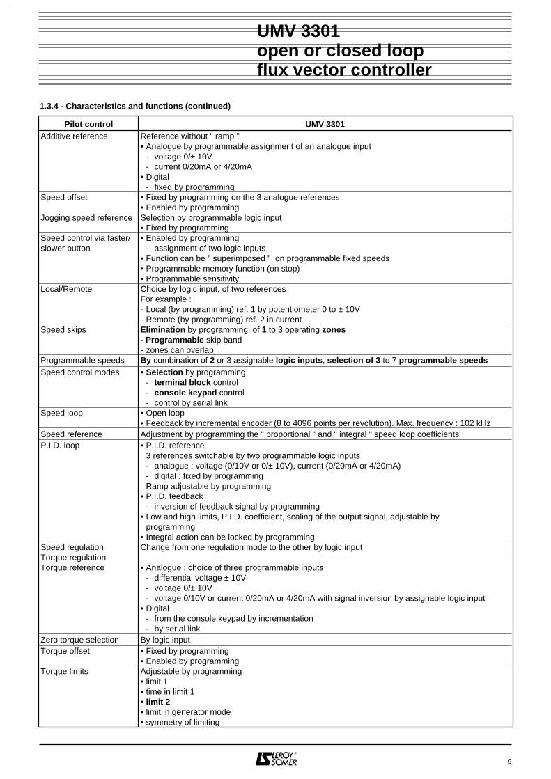
Pilot control UMV 3301Additive reference Reference without " ramp "
• Analogue by programmable assignment of an analogue input- voltage 0/± 10V- current 0/20mA or 4/20mA
• Digital- fixed by programming
Speed offset • Fixed by programming on the 3 analogue references• Enabled by programming
Jogging speed reference Selection by programmable logic input• Fixed by programming
Speed control via faster/slower button
• Enabled by programming- assignment of two logic inputs
• Function can be " superimposed " on programmable fixed speeds• Programmable memory function (on stop)• Programmable sensitivity
Local/Remote Choice by logic input, of two referencesFor example :- Local (by programming) ref. 1 by potentiometer 0 to ± 10V- Remote (by programming) ref. 2 in current
Speed skips Elimination by programming, of 1 to 3 operating zones- Programmable skip band - zones can overlap
Programmable speeds By combination of 2 or 3 assignable logic inputs, selection of 3 to 7 programmable speedsSpeed control modes • Selection by programming
- terminal block control - console keypad control - control by serial link
Speed loop • Open loop• Feedback by incremental encoder (8 to 4096 points per revolution). Max. frequency : 102 kHz
Speed reference Adjustment by programming the " proportional " and " integral " speed loop coefficients P.I.D. loop • P.I.D. reference
3 references switchable by two programmable logic inputs- analogue : voltage (0/10V or 0/± 10V), current (0/20mA or 4/20mA)- digital : fixed by programmingRamp adjustable by programming
• P.I.D. feedback- inversion of feedback signal by programming
• Low and high limits, P.I.D. coefficient, scaling of the output signal, adjustable by programming
• Integral action can be locked by programmingSpeed regulation Torque regulation
Change from one regulation mode to the other by logic input
Torque reference • Analogue : choice of three programmable inputs- differential voltage ± 10V- voltage 0/± 10V- voltage 0/10V or current 0/20mA or 4/20mA with signal inversion by assignable logic input
• Digital- from the console keypad by incrementation- by serial link
Zero torque selection By logic inputTorque offset • Fixed by programming
• Enabled by programmingTorque limits Adjustable by programming
• limit 1• time in limit 1• limit 2• limit in generator mode• symmetry of limiting

1.3.4 - Characteristics and functions (continued)
10
UMV 3301 open or closed loopflux vector controller
Operation UMV 3301Controller/motoradaptation
By programming :• motor characteristics
- nominal power- basic frequency- nominal speed- nominal motor frequency- nominal voltage- cosine ϕ- C max/C nominal- cooling
• controller characteristics- pilot control- switching frequency- overtorque request
Pilot control UMV 3301Starting modes By programming
• automatic or controlled• timed• start prohibited if a reference is present• locking of the reference in " jogging " mode• by automatic or controlled fault clearing• on reappearance of supply with motor flying restart
Stopping modes • By selection of logic states and weighting of faults causing stops- freewheel- on ramp- fast (in current limiting mode with braking resistor or DC bus voltage regulation)- with change to low speed (programmable time and level)- with D.C. injection (programmable speed threshold, level and duration of injection)- indexed with logic input DI 5
• Directly by the external fault input (EXT-FLT) instantaneous locking of the speed controller output (freewheel stop)
Electromechanical brake
Control via an assignable relay whose state depends on two assignable parameters• current threshold• speed threshold
Forward/Reverse control • By inversion of the reference polarity• By logic input
Logic inputs • 1 unlocking input• 1 dedicated Forward/Stop input• 1 dedicated Reverse/Stop input (or assignable logic input)• 5 inputs assignable by programmingor• 1 unlocking input• 1 dedicated Forward/Stop input• 1 dedicated input Reverse/Stop (or assignable logic input)• 4 inputs assignable by programming
Control logic Positive or negative• Selection by jumper
Analogue inputs • 1 differential reference input ± 10V assignable• 1 reference input 0/± 10V assignable• 1 reference input 0/10V or 0/20mA or 4/20mA assignable• 1 dedicated P.T.C. input (disabled by programming)
Console • Clear display of menus and parameters with language selection in 2 rows of 16 LCD characters
• Isolated RS 485 link- 9-pin SUB-D connector - access to reading of all parameters and the writing of accessible parameters
Serial link Isolated RS 485• connection (SUB-D 9-pin female)• MODBUS protocol

1.3.4 - Characteristics and functions (continued)
11
UMV 3301 open or closed loopflux vector controller
Operation UMV 3301Ramps • Main ramps assigned to general references
4 selection modes by programming- 1 single setting for ACC and DEC - FWD or REV- 1 setting for ACC FWD and REV, 1 for DEC FWD and REV- 4 settings ACC/FWD - DEC/FWD - ACC/REV - DEC/REV- 2 ACC settings with change by programmable speed threshold
2 DEC settings with change by programmable speed threshold• Ramps assigned to programmable speeds
- association or not with programmable speeds by programming- ACC and DEC associated or separated by programming- automatic selection corresponding to switching of programmable speeds
• ACC and DEC ramps assigned to jogging• Selection of " S " or " U "ramp by programming• Adjustment of " S " or " U " ramp curves by programming• Short-circuit ramp via logic input• Lock ramp via logic input
Minimum speed limit • With reference 0/10V or 0/20mA or 4/20mA, adjustment of minimum speed stops FWD andREV by programming• Automatic suppression of stops with faster/slower jogging reference
Maximum speed limit • Adjustment of maximum speed stops by programming- maximum forward speed/maximum reverse speed separately- max. forward/reverse speed symmetrically
• Stops maintained in torque regulationTorque limiting Selection by programming the limiting choice
• Symmetrical limiting of the motor and generator• Separate limiting of the motor or generator
- 2 programmable limits in motor mode- programmable time- 1 programmable limit in generator mode
Min. speed detection • Open loop : accuracy greater than the speed in min-1 corresponding to 1Hz of stator frequency.• Closed loop : accuracy greater than 1 min-1 with encoder 1024 points per revolution.
Switching via assignablelogic inputs
5 assignable logic inputs enabling selections :• Local/Remote control• additional speed reference• 1, 3 or 7 fixed programmable speeds• run or jog• faster/slower control• ramp short-circuiting• ramp locking• speed regulation/torque regulation• zero torque• direction of rotation • stopping modes• fault clearing• pilot control by external logic information
- starting- change in speed- reverse direction- stop
Special functions • Electromechanical brake handled by integration of engagement and release times• Weighting of safety actions (minor fault/major fault)
Programmable thresholds 2 circuits with analogue source and programmable logic output• level of tripping threshold adjustable by programming• hysteresis adjustable by programming• inversion of logic information by programming
Settings protected • By security code• Settings memorised after each modification

1.3.4 - Characteristics and functions (continued)
12
UMV 3301 open or closed loopflux vector controller
Signalling UMV 3301Display On the console
• Controller states• Parameter description and values• Faults
Display • 2 rows of 16 LCD characters• 1 LED indicating parameter-setting mode
Analogue outputs 2 outputs with programmable source• Scaling the source by programming• Conversion of output signal by programming• Selection of output signal by programming
- 0/20mA or 20/0mA, 4/20mA or 20/4mA, 0/10V or 10/0V, ± 10VDigital information • Motor frequency
• Motor voltage• Active current and motor current• Output torque on the motor shaft• Active power consumed by the motor• Overload level
Logic outputs • 2 outputs with single or double programmable logic sources- combination of both sources (AND function) by programming- inversion of logic sources and the AND output by programming- time delay adjustable by programming
• 2 relay outputs with single or double programmable logic sources- combination of both sources (AND function) by programming- inversion of logic sources and the AND output by programming- time delay adjustable by programming
• 1 output assignable by programming- programmable logic source with inversion of the logic source by programming- motor speed pulsed output
Logic information • Logic input state• Selection state (speed - ramps - starting and (or) stopping modes - jogging - P.I.D.)• State of programmed thresholds (speed or current)
Protection UMV 3301Thresholds and alarms • 4 detection circuits
- tripping threshold level adjustable by programming- hysteresis adjustable by programming- inversion of the logic information by programming- tripping time delay- selection of the effect on operation
• 1 detection of time in current limit- threshold level adjustable by programming- selection of the effect on operation
• 2 assignable time-based alarms- periods adjustable by programming- display of the duration before alarm
• 1 break of reference 4-20mA alarm • 1 ramp monitoring alarm• 1 rotation direction supervisor• 1 serial link and console supervisor• Motor earthing supervisor (for ratings ≥ 180T)
I x t overload Electronic thermal relay functionOvercurrent Monitoring and instantaneous break of current in IGBT transistorsController overheating Thermal protection of power bridgeMotor overheating • Management of PTC probes (assigned analogue input)
• Management of PTO probes directly or by assignable logic inputMotor protection • Motor phase loss monitoringSupply voltage • Mains fault with programmable time delay
• Mains undervoltage with programmable thresholdD.C. bus voltage • Undervoltage fault

1.3.4 - Characteristics and functions (end)
1.4 - Environmental characteristics1.4.1 - General
13
UMV 3301 open or closed loopflux vector controller
Option UMV 3301Resistance braking(4 quadrants)
Braking resistors• RF 27500, RF 37500, RF 55000, RF 75000, RF 110000 for 75T to 600T (consult LEROY-SOMER
for 75TH to 700TH)T - UMV modules TH - UMV modules• 100 : for UMV 3301 75T and100T • 85 : for UMV 3301 75TH to 150TH• 210 : for UMV 3301 120T to 150T • 175 : for UMV 3301 180TH to 340TH• 220 : for UMV 3301 180T to 265T• 300 for UMV 270T and 340T• Varies according to the application for UMV 3301 400T to 600T and 400TH to 700TH
Characteristics Level
Ingress protection• IP21 : 75T to 265T and 75TH to 340TH • IP20 : 270T to 600T and 400TH to 700TH
Storage temperature - 25°C to + 55°C, 12 months maximum with 5 to 95 % humidity Surronding air temperature - 10°C to + 40°C with 5 to 85 % humidityTransportation temperature -25°C to +55°C with 95 % maximum humidityAltitude • ≤ 1000 m without derating.
• Derating : 1 % of IN per 100 m above 1000m up to 4000 maximum.Humidity Without condensation.Vibration Conforms to IEC 62-2-36 (maximum acceleration : 1g for 10 to 50Hz)Shocks Conforms to IEC 68-2-27 (peak acceleration 15g - 11ms)Immunity and emissions See para 3.3Max. imbalance of supply voltage without chokes 2 %
If stored for a period of 12 months or more, the speed controller must be powered up (electronics and power supply) for 24hours once this limit is reached : repeat every six months afterwards.
If the supply voltage imbalance is equal or above 2 %, insert a chocke connected in series with the mains supply.
1.4.2 - Losses and dissipation (kW)Installing the inverter in a cubicle requires special precautions with regard to the size of the surrounding area. Check that theheat dissipation is adequate.
1.4.3 - Table for forced ventilation flow (m3 h-1)
Forced UMV 3301ventilation 75T(H) 100T(H) 120T(H) 150T(H) 180T(H) 220T(H)
300 300 500 500 500 500Flow (m3 h-1) 265T(H) 270T 340T 340TH 400T(H) 470T(H) 600T(H) 700TH
500 1200 1200 500 1200 1200 1200 1200
Switching UMV 3301Frequency 75T 100T 120T 150T 180T 220T 265T 270T 340T 400T 470T 600T
1.5 kW 1.9 kW 2.3 kW 2.6 kW 3.6 kW 4.1 kW 4.6 kW 8 kW 9.4 kW 10.3 kW 11.2 kW 13.7 kW2.5 kHz 75TH 100TH 120TH 150TH 180TH 220TH 265TH 340TH
1.7 kW 2.2 kW 2.5 kW 3.1 kW 3.5 kW 4.4 kW 5.2 kW 5.6 kW400TH 470TH 600TH 700TH7.1 kW 8.4 kW 10.1 kW 12.2 kW
2 kHz
UMV 330175T/100T 120T/150T 180T/220T 265T
Type 140µH 85µH 55µH 55µHCode SEL176NT000 SEL292NT000 SEL460NT000 SEL160NT000
Chockes 75TH/100TH 120TH/150TH 180TH/220TH 265TH/340THType 280µH 190µH 140µH 85µHCode SEL090NT000 SEL130NT000 SEL176NT000 SEL292NT000
Chockes

1.5 - Weight and dimensions
14
UMV 3301open or closed loopflux vector controller
PP1
L
L1
HH1
UMV 3301
C O N F I G U R A T I O NRE N A I N E M E N T 0 1T
Mem
RUN
PAR
MODE
STOPRESET
RUN + = Marche avant - Forward
RUN + = Marche arrière - Reverse
CDC - UMV
75Tto
265T
75THto
340TH
UMV 3301
C O N F I G U R A T I O NRE N A I N E M E N T 0 1T
Mem
RUN
PAR
MODE
STOPRESET
RUN + = Marche avant - Forward
RUN + = Marche arrière - Reverse
CDC - UMV
P
P1L
H
H1
270Tto
600T
400THto
700TH
Rating Dimensions (mm) Weight
UMV 3301 H H1 L L1 P P1 (kg)
75T(H) 928 850 526 459 420 405 100
100T(H) 928 850 526 459 420 405 102
120T(H) 958 850 526 459 420 405 104
150T(H) 958 850 526 459 420 405 106
180T(H) 1345 1238 666 596 506 491 170
220T(H) 1345 1238 666 596 506 491 190
265T(H) 1345 1238 666 596 506 491 215
270T 2150 2000 1200 - 620 600 400
340T 2150 2000 1200 - 620 600 400
340TH 1345 1238 666 596 506 491 215
400T 2185 2000 1200 - 620 600 440
400TH 2150 2000 1200 - 620 600 400
470T(H) 2185 2000 1200 - 620 600 440
600T 2385 2200 1200 - 620 620 500
600TH 2185 2000 1200 - 620 600 440
700TH 2385 2200 1200 - 620 620 500
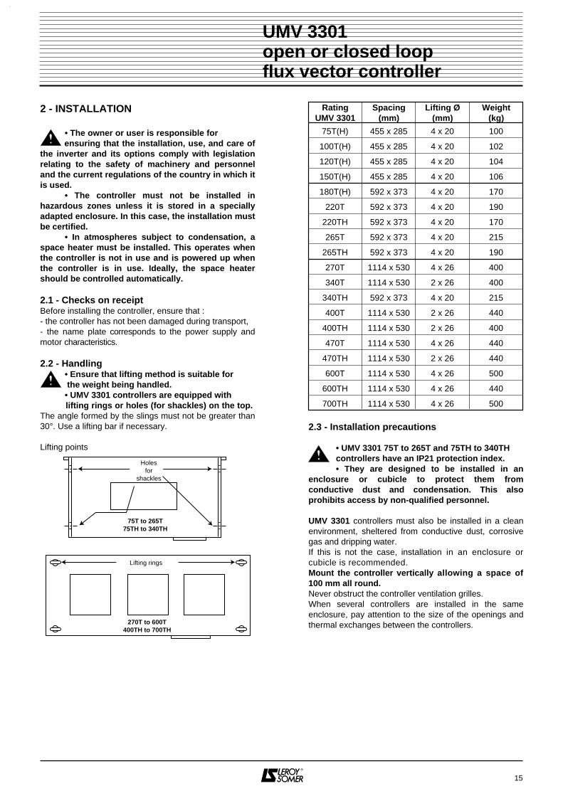
2 - INSTALLATION
• The owner or user is responsible for ensuring that the installation, use, and care ofthe inverter and its options comply with legislationrelating to the safety of machinery and personneland the current regulations of the country in which itis used.
• The controller must not be installed inhazardous zones unless it is stored in a speciallyadapted enclosure. In this case, the installation mustbe certified.
• In atmospheres subject to condensation, aspace heater must be installed. This operates whenthe controller is not in use and is powered up whenthe controller is in use. Ideally, the space heatershould be controlled automatically.
2.1 - Checks on receiptBefore installing the controller, ensure that :- the controller has not been damaged during transport,- the name plate corresponds to the power supply andmotor characteristics.
2.2 - Handling• Ensure that lifting method is suitable for the weight being handled.• UMV 3301 controllers are equipped with
lifting rings or holes (for shackles) on the top.The angle formed by the slings must not be greater than30°. Use a lifting bar if necessary.
Lifting points
2.3 - Installation precautions
• UMV 3301 75T to 265T and 75TH to 340THcontrollers have an IP21 protection index.• They are designed to be installed in an
enclosure or cubicle to protect them fromconductive dust and condensation. This alsoprohibits access by non-qualified personnel.
UMV 3301 controllers must also be installed in a cleanenvironment, sheltered from conductive dust, corrosivegas and dripping water.If this is not the case, installation in an enclosure orcubicle is recommended.Mount the controller vertically allowing a space of100 mm all round.Never obstruct the controller ventilation grilles.When several controllers are installed in the sameenclosure, pay attention to the size of the openings andthermal exchanges between the controllers.
15
UMV 3301open or closed loopflux vector controller
270T to 600T400TH to 700TH
Lifting rings
Holesfor
shackles
75T to 265T75TH to 340TH
RatingUMV 3301
Spacing(mm)
Lifting Ø(mm)
Weight(kg)
75T(H) 455 x 285 4 x 20 100
100T(H) 455 x 285 4 x 20 102
120T(H) 455 x 285 4 x 20 104
150T(H) 455 x 285 4 x 20 106
180T(H) 592 x 373 4 x 20 170
220T 592 x 373 4 x 20 190
220TH 592 x 373 4 x 20 170
265T 592 x 373 4 x 20 215
265TH 592 x 373 4 x 20 190
270T 1114 x 530 4 x 26 400
340T 1114 x 530 2 x 26 400
340TH 592 x 373 4 x 20 215
400T 1114 x 530 2 x 26 440
400TH 1114 x 530 2 x 26 400
470T 1114 x 530 4 x 26 440
470TH 1114 x 530 2 x 26 440
600T 1114 x 530 4 x 26 500
600TH 1114 x 530 4 x 26 440
700TH 1114 x 530 4 x 26 500

2.4 - Installing the speed controller
The UMV 3301 270T to 600T are supplied in a cubicleand only require the baseplate to be fixed to the ground.
Only 2 fixing screws per bracket for ratings 75T(H) to150T(H).
2.5 - Remote installation of the CDC - UMVconsoleThis is mounted :- either directly on the front panel of the controller,- or remotely on the front panel of the cubicle. Thedistance will then be less than 10 metres.Connection is via a 9-pin SUB-D connector situated atthe back of the console. The link cable must bescreened.
Mounting on the front panel of the cubicleFixing by 4 Ø 4.0 mm holes.Plan of the cut-out and drill holes :
16
UMV 3301open or closed loopflux vector controller
L2
H3
H2
H2
H2
H2
H4F
H5
UMV 3301
C O N F I G U R A T I O NRE N A I N E M E N T 0 1T
Mem
RUN
PAR
MODE
STOPRESET
RUN + = Marche avant - Forward
RUN + = Marche arrière - Reverse
CDC - UMV
75Tto
265T
75THto
340TH 22
146
26
40 25
97
Cut-out
Rating Dimensions (mm)
UMV 3301 H2 H5 H3 H4 L2F
Screw
75T(H) - 500 190 160 500 M8
100T(H) - 500 190 160 500 M8
120T(H) - 500 190 160 500 M8
150T(H) - 500 190 160 500 M8
180T(H) 170 - 207 351 640 M8
220T(H) 170 - 207 351 640 M8
265T(H) 170 - 207 351 640 M8
340TH 170 - 207 351 640 M8

3 - CONNECTIONS
• The voltages present on the power terminalblocks and in the cables connected to them
may cause fatal electric shocks. The controller stopfunction does not protect against these high voltages.
• The controller contains capacitors which remain charged at a fatal voltage even after the power supply has been cut.
• After the controller is powered down, wait 10mins (so that the internal circuits can discharge thecapacitors) before removing the protective devices.If in doubt, measure the voltage between powerterminals RF1 and LC1, if the measurement does notfall below 60 V, connect a 30W, 500Ω resistorbetween the terminals to discharge the capacitors.
• The controller power supply must beprotected against overloads and short-circuits.
• Do not ignore the rating of any protectivedevices.
3.1 - Motor connection3.1.1 - Terminal blockWARNING : The UMV 3301 output voltage is equivalent to the input voltage. The motors should therefore be connected in order to withstand a voltageequal to the power supply voltage.Ensure that the motor connection corresponds to the information on the name-plate.
3.1.2 - Auxiliary terminal blocks3.1.2.1 - Optional forced ventilation• LS MV motors of frame size 160 and above, can beequipped with a 3-phase 400V, 50Hz forced ventilation, connected as shown below.
Refer to the LS - MV motor catalogue for more information.
3.1.2.2 - Optional encoderLS - MV motors can be equipped with optional incrementalencoders.All installed encoders have the same electrical characte-ristics, unless otherwise specified. Connection is via afast-on 12-pin connector attached to the motor terminalbox.
Common characteristics :- supply : 5V,- consumption : 150 mA,- number of pulses/revolution : 1024,- number of channels : 2 channels with their complementand 0 marker.- maximum speed : 6000 min-1,- housing : injected Zamac,- external finish : epoxy,- protection : IP 65.
Connection
The encoder is connected to the UMV 3301 inverter by acable with shielded pairs, maximum length 150m.
Note : Depending on the manufacturer, the O markermay be labelled 0, C or Z.
Precautions :- connect or disconnect the controller encoder whenpowered down,- keep the encoder shielded cable separate from the powercables and avoid parallel routing.
17
UMV 3301open or closed loopflux vector controller
connectionΥ400V :
W2
U1
U2
V1
V2
W1
Connector pin Function
1 - power supply
2 + power supply
3 A
4 B
5 O
6 A
7 B
8 O9 Free terminal
10
11
12

3.2 - Connecting the controller3.2.1 - Access to terminal blocks3.2.1.1 - UMV 3301 75T to 265T and 75TH to 340THTo access the terminal blocks, remove the cover locatedunder the CDC - UMV console. Only the bottom 2screws need to be removed, the other two should just beloosened.
- Loosen the screws marked .- Remove the protective elements, retaining the cableentries.- Wire the terminals situated at the bottom of thecontroller first.
WARNING : It is essential :- not to remove the air guidance plate, - to replace all protective plates,- to use cable entries when wiring in order to protect thecables.
- The power terminal block is composed of 1 group of 11terminals.- The power supply for the electronics is to be providedon a spring type terminal block.- The control terminal block is composed of 5 removablescrew connectors and a 9-pin female SUB-D connector.
3.2.1.2 - UMV 3301 270T to 600T and 400TH to 700THOpen the cubicle doors to access the terminals.
18
UMV 3301open or closed loopflux vector controller
UMV 3301 75T to 265T and 75TH to 340TH
3.2.2 - The power terminal blockWARNING :- Never connect a circuit such as a capacitor bank between the controller output and the motor.- Never connect the A.C. supply to the U.V.W. terminals.
3.2.2.1 - UMV 75T to 265T and 75TH to 340TH
L1 L2 L3 PE B- B+ RF PE U V W
Electronics power supplyterminal block
L1
B-
L2
L3
+
-
U
V
WT - UMVoption
RF
B+
Terminal connectorsLabels Functions 75T(H) to 150T(H) 180T(H) to 340T(H)
Max. terminalscrew torque
(Nm)Bolt Ø
Width
(mm)
Length
(mm)
Max. terminalscrew torque
(Nm)Bolt Ø
Width
(mm)
Length
(mm)
L1, L2, L3 3-phase controller supply
B+, RFConnecting the RF optionalbraking resistor via a thermal relay
B+, B-
Supplying the controllers via theD.C. bus :• 510V to 620V ± 10% for 270T to 600T
• 740V to 980V ± 10% for400TH to 700TH
(see § 3.2.5.3 for warnings)
10 M10 26 33 15,5 M12 36 24
U, V, W Connecting the motorPE Earthing the controller and motor 6 M8 20 20 10 M10 26 33
C O N F I G U R A T I O NRE N A I N E M E N T 0 1T
Mem
RUN
PAR
MODE
STOPRESET
RUN + = Marche avant - Forward
RUN + = Marche arrière - Reverse
CDC - UMV
Remove
Unscrew

3.2.2.2 - UMV 270T to 600T and 400TH to 700TH
These terminals are mounted optionally
Drilling the bars
3.2.3 - The electronics supply terminal block
• It is imperative to ensure that the voltage between the neutral of the power supply and
the neutral of the electronics supply is lower thanthe value of the voltage on each power supplyphase.
• For UMV 3301 75T to 265T and 75TH to340TH, both power supply cables must be protectedby a 2A semi time delayed fuses or a 2A D curve cir-cuit-breaker.
• For 230Vac control terminals, if external po-wer is provided, then additional transient voltagesurge suppressors with clamping voltage of 2kVAmax must be provided.
3.2.3.1 - UMV 75T to 265T and 75TH to 340THPower supply for electronics is to be provided on termi-nal block located on the left hand side of the controlboard.
3.2.3.2 - UMV 270T to 600T and 400 TH to 700 THPower supply for electronics is to be provided on termi-nal block located on the right hand side of the powerbars.
When the motor is stopped, it is possible to power downthe forced ventilation while keeping the electonic powe-red. Replace connection between the two terminals loca-ted on the right with the fan Start/Stop dry contact com-mands.
Warning :• In this configuration, power up 10 seconds before arun command, and power down 15 minuts after astop command.• The contact must allow to switch a 5A inductiveload under 230V.
19
UMV 3301open or closed loopflux vector controller
* Only on option Power supplyterminal block
for the electronics
L1 L2 L3 PE -B +B* * * *
U V W PE RF1 RF2
L1
+B
-B
L2
L3
+
-
U
V
WT - UMVoption
RFoption
RF1
RF2
Label FunctionL1 - L2 - L3 3-phase controller supply
Earthing the controller and motor
+B, -B
Supplying the controller via the D.C. bus•510V to 620V ±10% for 270T to 600T•740V to 980V ±10% for 400TH to 700TH (see § 3.2.5.3 for warnings)
U - V - W Connecting the motor
RF1 - RF2 Connecting the RF braking resistors via athermal relay
Connectingthe bars
Rating TerminalsØ
Screw - nutSection
(mm)270T All 2 x M10 40 x 5340T PE 2 x M10 40 x 5400T L1, L2, L3, -B, +B, U,
V, W, RF1, RF2 2 x M10 50 x 5
PE 2 x M10 40 x 5470T L1, L2, L3, -B, +B, U,
V, W, RF1, RF2 2 x M10 40 x 10
PE 2 x M10 40 x 10600T L1, L2, L3, -B, +B, U,
V, W, RF1, RF2 2 x M10 50 x 10
PE 2 x M10 40 x 5400TH L1, L2, L3, -B, +B, U,
V, W, RF1, RF2 2 x M10 40 x 5
PE 2 x M10 40 x 5470TH L1, L2, L3, -B, +B, U,
V, W, RF1, RF2 2 x M10 40 x 5
600TH PE 2 x M10 40 x 5700TH L1, L2, L3, -B, +B, U,
V, W, RF1, RF2 2 x M10 40 x 10
UMV 3301
H2H1
L2
L1
Width of Dimensions (mm)bar (mm) L1 L2 H1 H2 Ø
40 10 30 10 30 1150 12,5 25 12,5 35 11
Supply (AC)75Tto
265T
75THto
340TH230V400V460V
-
230V500V600V690V
Supply (AC)270T
to600T
400THto
700TH230V400V460V
-
230V500V600V690V

20
UMV 3301open or closed loopflux vector controller
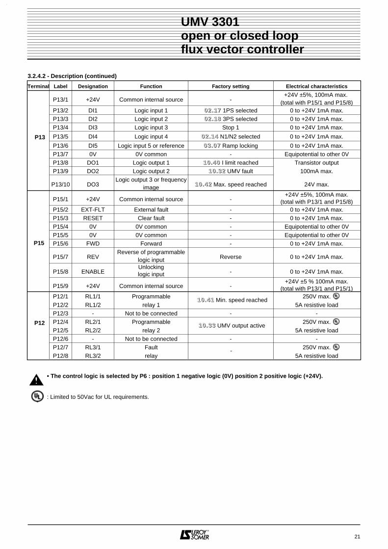
3.2.4 - Control terminal block3.2.4.1 - GeneralThe control terminal block comprises 5 removable screw connectors and a 9-pin female SUB-D 9 connector.
3.2.4.2 - Description
AA +5V
CO
D0V
CO
DB B O O
P11P3
S1
AI1
++
10V
-10V
AI1
-A
I2A
I3T
HE
RM
0V AO
1A
O2
0V
P16
DI1
+24
V
DI2
DI3
DI4
DI5
0V DO
1D
O2
DO
3
P13
EX
T-F
LT+
24V
RE
SE
T0V 0V F
WD
RE
VE
NA
BLE
+24
V
P15
RL1
2R
L11
RL2
1R
L22
RL3
1R
L32
P12
1
ON
OFF2
P6
K1 K2 K3
1
1
CR4CR3 CR5
Optional encoder feedback
Seriallink
Assignableanalogue
inputs
Assignableanalogueoutputs
Logic inputs
Faultrelays
Assignablerelays
Assignablelogic
inputs
Assignablelogic
outputs
Controllogic
Terminal Label Designation Function Factory setting Electrical characteristics
P11/1P11/2
AA
Isolated encoder feedbackComplementary channel A - 5V 20mA
P11/3P11/4
+5V - COD0V - COD
Encoder power supply- 5V ±5% 100mA max.
P11/5P11/6
BB
Isolated encoder feedbackComplementary channel B - 5V 20mA
P11/7P11/8
OO
Isolated encoder feedbackComplementary 0 marker
-5V 20mA
1 - 0V -Isolated from P16/8, P16/11,
P13/7, P15/4 and P15/52 - TX transmission - Isolated by optocoupler
3 - RX reception - Isolated by optocoupler
4 - Not connected - -P3 5 - Not connected - -
6 - TX transmission - Isolated by optocoupler
7 - RX reception - Isolated by optocoupler
8 - Not connected - -9 - Not connected - -
P16/1 +10V Internal source - +10V ±2 % 10mA max.
P16/2 AI1+Differential analogue input
1 (+) 00 22 .. 11 11 Speed N° 1 (0-10V)-10V to +10V
impedance 10kΩP16/3 -10V Internal source - -10V ±2 % 10mA max.
P16/4 AI1-Differential analogue input
1 (+) 00 22 .. 11 11 Speed N° 1 -10V to +10V Impedance 10kΩP16/5 AI2 Analogue input 2 00 44 .. 33 66 Torque limiting (0-10V) ±10V Impedance 15kΩ
P16/6 AI3Analogue
input 3 00 22 .. 11 22 Speed N° 2 (4-20mA)
0 to +10V (8 kΩ) 4 to 20mA or
0 to 20mA (100Ω)
P16/7 THERM
Analogueinput -
0 to 5V Impedance 40kΩfault > 3.3kΩ,reset < 1.8kΩ
P16/8 0V 0V common Equipotential to other 0VP16/9 AO1 Analogue output 1 Current image (4-20 mA) 0-20mA, 4-20 mAP16/10 AO2 Analogue output 2 Speed image (4-20 mA) or ±10V 10mA max.P16/11 0V 0V common - Equipotential to other 0V
P11
P16
21
UMV 3301open or closed loopflux vector controller
Terminal Label Designation Function Factory setting Electrical characteristics
P13/1 +24V Common internal source -+24V ±5%, 100mA max.
(total with P15/1 and P15/8)P13/2 DI1 Logic input 1 00 22 .. 11 77 1PS selected 0 to +24V 1mA max.P13/3 DI2 Logic input 2 00 22 .. 11 88 3PS selected 0 to +24V 1mA max.P13/4 DI3 Logic input 3 Stop 1 0 to +24V 1mA max.
P13/5 DI4 Logic input 4 00 22 .. 11 44 N1/N2 selected 0 to +24V 1mA max.
P13/6 DI5 Logic input 5 or reference 00 33 .. 00 77 Ramp locking 0 to +24V 1mA max.P13/7 0V 0V common - Equipotential to other 0VP13/8 DO1 Logic output 1 11 00 .. 44 00 I limit reached Transistor outputP13/9 DO2 Logic output 2 11 00 .. 33 22 UMV fault 100mA max.
P13/10 DO3Logic output 3 or frequency
image 11 00 .. 44 22 Max. speed reached 24V max.
P15/1 +24V Common internal source -+24V ±5%, 100mA max.
(total with P13/1 and P15/8)P15/2 EXT-FLT External fault - 0 to +24V 1mA max.P15/3 RESET Clear fault - 0 to +24V 1mA max.P15/4 0V 0V common - Equipotential to other 0VP15/5 0V 0V common - Equipotential to other 0VP15/6 FWD Forward - 0 to +24V 1mA max.
P15/7 REVReverse of programmable
logic input Reverse 0 to +24V 1mA max.
P15/8 ENABLEUnlockinglogic input - 0 to +24V 1mA max.
P15/9 +24V Common internal source -+24V ±5 % 100mA max.
(total with P13/1 and P15/1)P12/1 RL1/1 Programmable 250V max.P12/2 RL1/2 relay 1 5A resistive loadP12/3 - Not to be connected - -P12/4 RL2/1 Programmable 250V max.P12/5 RL2/2 relay 2 5A resistive loadP12/6 - Not to be connected - -P12/7 RL3/1 Fault 250V max.P12/8 RL3/2 relay 5A resistive load
3.2.4.2 - Description (continued)
P15
P12
11 00 .. 44 11 Min. speed reached
11 00 .. 33 33 UMV output active
-
P13
• The control logic is selected by P6 : position 1 negative logic (0V) position 2 positive logic (+24V).
: Limited to 50Vac for UL requirements.

3.2.5 - Special connections3.2.5.1 - Connecting the serial linkThis serial link is created in accordance with standardRS 485/RS 422 which allows differential transmissionand reception of data via 4 wires. The maximum lengthof cables must be 1200m.
RS 485/RS 422 standard :
The S1 selector switch located on the control circuitallows impedance matching resistors to be used.
Note : With the RS 485 standard, it is possible tocommunicate with up to 32 controllers connected on thesame line from a single P.C.Each controller has a unique serial address.
RS 485 serial link with 32 controllers per port
Protocol : MODBUS.
3.2.5.2 - Connecting the parameter-setting option viaPEGASE softwareThis can be connected either on a single line via theconsole SUB-D, or on a network via the terminal blockSUB-D.• On a single line, remove the CDC-UMV console andconnect a CD-CORD cable to the RS 232/RS 485 unit,at the RS 485 end.The unit does not need to be powered externally.
WARNING :The maximum length of the shielded cable must notexceed 5 metres.
• With a network, on the control circuit SUB-D P3,connect a CD-CORD cable to the RS 485 end of the RS232/RS 485 unit. Use a male/female converter forconnection.The terminal box needs to be powered externally.
3.2.5.3 - Supply via the D.C. busIt is possible to supply several UMV 3301 controllersfrom one 510V to 620V ± 10 % D.C. bus for " T " ratingsand 668V to 1000V for " TH " ratings.Connection is between terminals B+ and B-.The protective fuses used for each controller areindicated in section 3.4; two fuses are necessary percontroller.
Drive settings :00 99 .. 11 11 = 10.4900 99 .. 11 22 = No00 99 .. 11 55 = No00 99 .. 11 66 = 0
22
UMV 3301 open or closed loopflux vector controller
3 7 2 6 1
Transmittertwisted
shielded wires
Receivertwisted
shielded wires
RX
Reception Transmission
0V P3 9-pinfemale SUB-D
0V
RX TX TX
PE
Controller 9-pin SUB-D
Serial link 9-pin SUB-D
30 31 32
R T R T R T
Port A Port B
P.C.
R
R T
33 34
T R TR R
RT
UMV30
UMV31
UMV32
UMV33
UMV34
Serial address
unique tocontroller
R : receiver inputT : transmitter output
5
Interface end9-pin female
SUB-D
UMV 3301 end9-pin male
SUB-D
4
3
2
16
7
8
9
5
16
2
3
4
7
8
9
5
Interface end9-pin
SUB-D female9-pin
SUB-D male
4
3
2
16
7
8
9
5
16
2
3
4
7
8
9
CD - CORD cable
B+
P12.1
P12.2B-
Remote
120Ω 500w
Controlboard
3.3 - Electrical and electromagnetic phenomena
3.3.1 - GeneralThe power structure of frequency inverters leads to theoccurrence of two types of phenomena :- low frequency harmonic feedback on the mains powersupply,
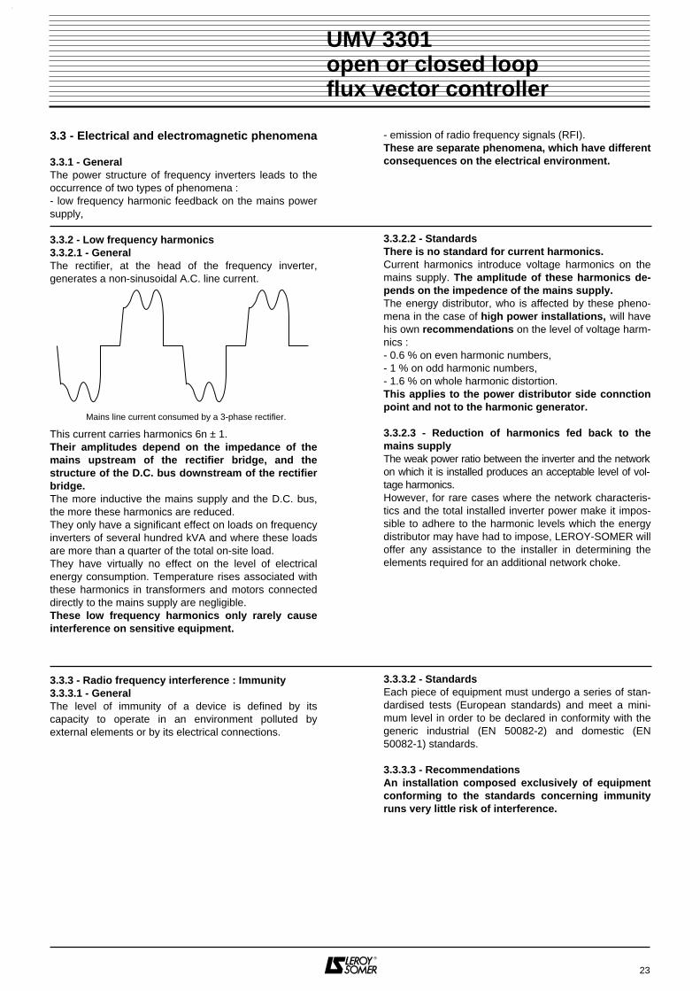
3.3.2 - Low frequency harmonics3.3.2.1 - GeneralThe rectifier, at the head of the frequency inverter,generates a non-sinusoidal A.C. line current.
This current carries harmonics 6n ± 1.Their amplitudes depend on the impedance of themains upstream of the rectifier bridge, and thestructure of the D.C. bus downstream of the rectifierbridge.The more inductive the mains supply and the D.C. bus,the more these harmonics are reduced.They only have a significant effect on loads on frequencyinverters of several hundred kVA and where these loadsare more than a quarter of the total on-site load.They have virtually no effect on the level of electricalenergy consumption. Temperature rises associated withthese harmonics in transformers and motors connecteddirectly to the mains supply are negligible.These low frequency harmonics only rarely causeinterference on sensitive equipment.
3.3.3 - Radio frequency interference : Immunity3.3.3.1 - GeneralThe level of immunity of a device is defined by itscapacity to operate in an environment polluted byexternal elements or by its electrical connections.
- emission of radio frequency signals (RFI).These are separate phenomena, which have differentconsequences on the electrical environment.
3.3.2.2 - StandardsThere is no standard for current harmonics.Current harmonics introduce voltage harmonics on themains supply. The amplitude of these harmonics de-pends on the impedence of the mains supply.The energy distributor, who is affected by these pheno-mena in the case of high power installations, will havehis own recommendations on the level of voltage harm-nics :- 0.6 % on even harmonic numbers,- 1 % on odd harmonic numbers,- 1.6 % on whole harmonic distortion.This applies to the power distributor side connctionpoint and not to the harmonic generator.
3.3.2.3 - Reduction of harmonics fed back to themains supplyThe weak power ratio between the inverter and the networkon which it is installed produces an acceptable level of vol-tage harmonics.However, for rare cases where the network characteris-tics and the total installed inverter power make it impos-sible to adhere to the harmonic levels which the energydistributor may have had to impose, LEROY-SOMER willoffer any assistance to the installer in determining theelements required for an additional network choke.
3.3.3.2 - StandardsEach piece of equipment must undergo a series of stan-dardised tests (European standards) and meet a mini-mum level in order to be declared in conformity with thegeneric industrial (EN 50082-2) and domestic (EN50082-1) standards.
3.3.3.3 - RecommendationsAn installation composed exclusively of equipmentconforming to the standards concerning immunityruns very little risk of interference.
23
UMV 3301 open or closed loopflux vector controller
Mains line current consumed by a 3-phase rectifier.

3.3.4 - Radio frequency interference : Emission3.3.4.1 - GeneralFrequency inverters use high-speed switches(transistors, semi-conductors) for switching high voltages(around 550V) and high frequency currents (severalkHz). This provides a high level of efficiency and a lowlevel of motor noise.They also therefore generate radio frequency signalswhich may disturb the operation of other equipment ordistort sensor measurements : - due to high frequency leakage currents which escapeto earth via the inverter/motor cable leakage capacitanceand the leakage capacitance of the motor across the me-tal structures which support the motor.- by conduction or feedback of radio frequency signalson the supply cable : conducted emissions,- by direct radiation close to the power supply cable orthe inverter/motor cable : radiated emissions,These phenomena are of direct interest to the user.The frequency range concerned (radio-frequency) doesnot affect the energy distributor.
3.3.5 - Elementary precautionsThese are to be taken into account during the designstage and also when wiring the cubicle and the externalelements. In each paragraph, they are classed indecreasing order of influence on correct operation of theinstallation.
3.3.5.1 - Design1) Choice of materialGive priority to components whose level of immunityconforms to the generic immunity standards EN 50082-1and EN 50082-2, and mount them in a steel cubicle.2) Locating the inverterInstall the inverter as near to the motor as possible inorder to reduce the length of the cable.
3.3.5.2 - Installing the inverter and its relevant com-ponents in the cubicle1) Fix the inverter and components onto a metal grille orbase plate which is unpainted or paint-free around itsfixing points.2) Fix the plate at several paint-free points on the bottomof the cubicle.
3.3.5.3 - Wiring inside cubicles1) Do not place control cables and power cables in thesame cable trough (distance 0.5m minimum).2) For control cables, use twisted shielded cables.3) Relays and contactors which are electrically linked tothe inverter should be equipped with an RC filter.
3.3.4.2 - StandardsThe maximum level of emissions is fixed by the genericindustrial (EN 50081-2) and domestic (EN 50081-1)standards.
3.3.4.3 - Recommendations• Experience shows that the level fixed by standards EN50081-1 and 50081-2 does not necessarily need to berespected in order to be free of interference phenomena.• following the elementary precautions in the followingparagraph generally results in correct operation of theinstallation.
3.3.5.4 - Wiring outside the cubicle1) Isolate the power cables from the control cables.2) Link the motor earth terminal directly to that of theinverter.3) Place the motor supply cables, as well as the accom-panying cable which links the motor earth to the inverterearth, in a metal trough. Mecanically link this trough tothe cubicle and to the metal structure supporting the mo-tor. Fix the conductors on a plate at the bottom of thetrough.4) Isolate sensitive elements (probes, sensors etc.) frommetal structures which could have the same common asthe motor support.
3.3.5.5 - Ground wiringThe immunity and level of radio frequency emissions aredirectly linked to the quality of the ground connections.The metallic grounds must be mechanically connected toeach other with the largest possible electrical contactsurface. In no case should the ground connections,designed to ensure the protection of personnel by linkingmetallic grounds to earth via a cable, be replaced byearth connections.
24
UMV 3301 open or closed loopflux vector controller

3.3.6 - Additional precautionsRespecting the elementary precautions of the previousparagraph generally ensures correct operation of theinstallation. However, its immunity can be increased byfollowing the additional precautions below. These are lis-ted in order of importance.
3.3.6.1 - Installation and wiring of an MC chokeThe majority of interference phenomena are caused byhigh frequency leakage currents which escape to theearth via the inverter/motor cable and via the metalstructures supporting the motor.MC chokes are used to reduce the leakage currents. Thegreater the length of the inverter/motor cable, the moreimportant is their role.
3.3.6.2 - Using RFI filtersUsing RFI filters reduces the level of radio frequencysignal emissions. They enable UMV 3301 components toconform to the EN 50081-1 and EN 50081-2 directiveson conducted and radiated radio frequency emissions.Depending on the controller used, install therecommended RFI filter as described in the table below,between the mains and the controller input.
Rules to follow when using filters- Install the UMV 3301 in a metal cubicle in accordancewith the wiring recommendations described in the pre-vious paragraphs.- Install the filter as near to the cubicle incoming mainsas possible. Fix the filter on the same base grille as thecontroller.
WARNING :Using a RFI filter on a IT power supply is not recom-mended. Indeed, the capacitance leakage of the filtermay disturb the operation of the permanent insula-tion controller used to detect earth fault. With this ty-pe of installation, it is recommended to use ferriterings on the motor cables at the drive output (see pa-ragraph 3.3.6.1).
25
UMV 3301open or closed loopflux vector controller
Cable :3 conductors
+ earth
U
V
W
MC chokes installed as near to the inverter as possible
UMV rating MC choke reference Quantity
75T FAP038FE001 3
100T FAP038FE001 3
120T FAP038FE001 3
150T FAP038FE001 3
180T FAP055FE001 3
220T FAP055FE001 3
265T FAP055FE001 3
270T
340T
400T
470T
600T
Consult LEROY-SOMER
UMV Filter reference
rating High overtorque Low overtorque
75T & 100T FLT 3359 HV - 180 FLT 3359 HV - 180
120T FLT 3359 HV - 180 FLT 3359 HV - 250
150T FLT 3359 HV - 250 FLT 3359 HV - 320
180T FLT 3359 HV - 320 FLT 3359 HV - 320
220T FLT 3359 HV - 320 FLT 3359 HV - 400
265T & 270T FLT 3359 HV - 400 FLT 3359 HV - 600
340T FLT 3359 HV - 600 FLT 3359 HV - 600
400T FLT 3359 HV - 600 FLT 3359 HV - 1000
470T & 600T FLT 3359 HV - 1000 FLT 3359 HV - 1000
UMV Filter reference
rating High overtorque Low overtorque
75TH & 100 TH FLT 3359 HV - 180 FLT 3359 HV - 180
120TH to 265TH FLT 3359 HV - 250 FLT 3359 HV - 250
340TH FLT 3359 HV - 320 FLT 3359 HV - 320
400TH FLT 3359 HV - 400 FLT 3359 HV - 400
470TH FLT 3359 HV - 600 FLT 3359 HV - 600
600TH FLT 3359 HV - 400 FLT 3359 HV - 600
700TH FLT 3359 HV - 1000 FLT 3359 HV - 1000

26
UMV 3301 open or closed loopflux vector controller
3.3.7.2 - Conducted and radiated emissionsRules to be respected for bringing UMV 3301 components into conformity with directives EN 50081-1 and EN 50081-2 onconducted and radiated radio frequency emissions :- adhere to the wiring rules in section 3.3.5,- use RFI filters as described in section 3.3.6.2,- use a switching frequency equal to 2.5 kHz,- length of motor cables limited to 20m for the EN 50081-1 directive and 80m for the EN 50081-2 directive.
3.3.7 - Conformity to standardsTests carried out in the conditions imposed by the standards show that the UMV 3301, if installed and connected according tothe instructions in sections 3.3.5 and 3.3.6, conforms to EMC directive 89/336/EEC, modified by 92/31/EEC.
3.3.7.1 - ImmunityUMV 3301s conform to international immunity standards.
Standard Type of immunity Application LevelEN 61000-4-2 Electrostatic discharge Product enclosure Level 3 (industrial)EN 61000-4-3 Radiated radio frequency Product enclosure Level 3 (industrial)ENV 50140* Radiated radio frequency Product enclosure Level 3 (industrial)ENV 50141* Conducted radio frequency Control and power cables Level 3 (industrial)EN 61000-4-4* Rapid transients in succession Control cables Level 4 (reinf. industrial)
Power cables Level 3 (industrial)CEI 1000-4-11 Voltage dips, momentary cuts and voltage
variations Supply cables Level 4
EN 50082-1 Generic immunity standardPart 1 : residential, commercial and lightindustry
- Conforming
EN 50082-2 Generic immunity standardPart 2 : industrial environmentConcerns the basic standards marked*
- Conforming

27
UMV 3301 open or closed loopflux vector controller
NOTES

28
UMV 3301 open or closed loopflux vector controller
3.4 - Protection• Use the specified size of protective fuse.• The cable definition can vary depending on the current legislation of the country, which always takes
precedence over the tables below.• In no case should these tables replace the current standards.• Refer to § 3.2.2.1 for the maximum terminal screw torque.
Table of fuses and cable cross-sections recommended for the cubicles for copper wiresWARNING :• Cable cross-sections do not take line drops into account.• To conform to UL requirements, equipment suitable for use on a circuit capable of delivering not more than
10000 rms symmetrical Amps for 75TH to 150TH, or 18000 rms symmetrical Amps for 180TH to 340TH, 600Vmaximum.
• UL listed closed-loop connectors sized according to the field wiring, shall be used for power connections.
: Use 600V class J fuses e.g. Ferraz Shawmut A4J series.
Output current Mains current D.C. bus current Mains Mains Motor Mains D.C. busUMV 3301 (A) (A) (A) gl fuses UL fuses cables cables cables
400V 460V 400V 460V (A) (A) (mm2) (mm2) (mm2)
75THigh Low
112145
110136
110136
108146
108146
125160 200
5050
5050
5050
100THigh Low
145180
142169
142169
146175
146175
160200 250
7070
7070
7070
120THigh Low
180220
176207
176197
175214
165204
200250 300
9595
9595
9595
150THigh Low
220260
216244
216226
214257
204242
250250 300
120120
120120
120120
180THigh Low
260315
255296
255282
257350
242328
315315 400
150150
150150
150150
220THigh Low
315380
309357
309338
350480
328460
315400 500
185185
185185
2 x 952 x 95
265THigh Low
380480
372451
372423
425535
370465
400500 600
1852 x 95
1852 x 95
2 x 1202 x 120
270THigh Low
380490
372462
372423
425540
370465
400500 -
340THigh Low
480580
470545
470508
580680
500590
500630 - For cables outside the cubicle
400THigh Low
580680
568639
568602
630750
550650
630800 - consult your cable
470THigh Low
680820
666773
666667
730873
635750
800800 - supplier
600THigh Low
860970
843907
843799
8901042
770870
10001000 -

29
UMV 3301 open or closed loopflux vector controller
Switching frequency : 2.5 kHz for 75T to 600T and 75TH to 340TH ; 1.7kHz for 400TH to 700TH. Only when the UMV 3301 is supplied via the D.C. bus.Note : Use a 2A curve D circuit breaker or semi-timed 2A (5A for ratings ≥ 400TH) fused isolator as a circuit-breaking and protectiondevice for the 2 electronics supply wires for ratings 75T to 265T.
: Use 600V class J fuses e.g. Ferraz Shawmut A4J series.
Output current Mains current D.C. bus current Mains Mains Motor Mains D.C. busUMV 3301 (A) (A) (A) gl fuses UL fuses cables cables cables
(525 to 690Vac) (A) (A) (mm2) (mm2) (mm2)
75THHigh Low
6385
5983
73102
100100 125
2525
2525
2525
100THHigh Low
86115
81113
99138
125125 150
3535
3535
3535
120THHigh Low
101135
95132
116162
160160 200
5050
5050
5050
150THHigh Low
116155
109152
134186
160200 250
7070
7070
7070
180THHigh Low
142190
133186
164228
200200 300
9595
9595
9595
220THHigh Low
165225
155221
190270
250250 300
120120
120120
120120
265THHigh Low
205280
193274
236336
315315 400
150150
150150
150150
340THHigh Low
255340
240333
294408
400400 500
185185
185185
185185
400THHigh Low
300400
282392
345480
400500 -
470THHigh Low
350450
329441
403540
500500 - For cables outside the cubicle
600THHigh Low
450580
423568
518696
630630 - consult your cable supplier
700THHigh Low
500670
470657
576804
630800 -

30
UMV 3301 open or closed loopflux vector controller
3.5 - Wiring diagramFactory configuration - Simplified setup using the user menu
QS : Fused isolator.QF : 2A circuit-breaker or 2A fused isolator.SB1 : Off button.SB2 : On button.KM1 : Line contactor.FR : Thermal relay.AU : Customer safety devices.RP : 10 kΩ potentiometer. : see § 3.2.3 for details.
L1
L2
L3
QS
Mai
ns
U V W
KM1
M3
Console
SB1
8
RL3
RL2
RL1
7
Faultrelay
12345678
P3
Serial link
P12
P22
P11
R - FMV Option
UMV 3301
Optional encoder feedback
5
4
Assignablerelay2
1
Assignablerelay
KM1
SB2
KM1
FR
FR
AU
QF
Fu1
Remote powersupply
Protection of optional resistors via thermal relayis essential
The number of power-ups is limited to 20 per hour
Encoder option
C O N F I G U R A T I O NRE N A I N E M E N T 0 1T
Mem
RUN
PAR
MODE
STOPRESET
RUN + = Marche avant - Forward
RUN + = Marche arrière - Reverse
QF
RFI
filter
option
T - UMVoption
RF2 RF1
3456789
10
21
34567
89
10
21+10V
AI1+-10VAI1-AI2AI3THERM
0VAO1
+10VSpeed reference 0-10V or potentiometer
Torque limitation 0-10VSpeed reference 4-20mA
Image of current 4-20mA
Speed reference selection
Priority freewheel stopAI1/AI3 selectionLock ramps
Current limit reachedUMV faultMax. speed reached
External fault or shunt if no fault management
Clear fault
Run/Stop forwardRun/Stop reverseUnlock or freewheelstop
Minimumspeed
reached
UMVoutputactive
Motor PTC or shunt if PTC not present
AO2
+24VDI1DI2DI3DI4DI50VDO1DO2DO3
+24VE.F.Res.0V0VFWDREVEna.+24V
P15
P13
P16
3456789
21
RP
110VImage of speed 4-20mA
DI100011
DI200101
DI401
0 or 10 or 10 or 1
Ref.AI1+AI3VP2VP1VP3
Selection
Diagram to be modified depending on application by referring to
standard EN 60204 (safety circuit)
460V
400V
230V
Table for logic and relay output states
Output Factory setting StateDO1 Current limit
reached 10.470 : Powered down or limitnot reached1 : Limit set in 04.36 hasbeen reached
DO2 UMV fault 10.32 0 : Powered down or UMVnot faulty1 : UMV faulty
DO3 Max. speed reached 10.42
0 : Powered down or speedreached1 : Speed not reached(threshold 05.22)
RL1 Min. speed reached 10.41
Open: Powered down ormin. speed not reachedClosed : Minimum speedreached (threshold 05.12)
RL2 UMV output active10.33
Open : Powered down orUMV stoppedClosed : UMV operating
RL3 UMV fault (fixed) Open: Powered down orUMV faultyClosed : UMV not faulty(10.32)

4 - COMMISSIONING
4.1 - Using the CDC - UMV console4.1.1 - Presentation
31
UMV 3301open or closed loopflux vector controller
Mem
RUN
PAR
MODE
STOPRESET
C O N F I G U R A T I O NRE N A I N E M E N T 0 1T
RUN + = Marche avant - Forward
RUN + = Marche arrière - Reverse
CDC - UMV
Used to change from READ mode to PARAMETER-SETTING mode and vice versa
Cursor for moving around the various menus ( , ) and modifying the content of theparameters ( , )
For memorising the settings. These settings are memorised in EEPROM type memorieswhich do not require any protected power supply.
Key Used when the device is configured for control via the console for giving the run command,together with the cursor keys
RUN + for forward operation
RUN + for reverse operationUsed when the device is configured for control via the console for giving the stop command,and can also be used as a fault reset button
LEDOn : reminds the user that the UMV 3301 is in parameter-setting modeFlashing : a setting has been modified but not memorised
DisplayClearly displays menus and parameters, with selection of the language, with 2 rows of 16LCD characters
MODE
MEM
RUN
STOPRESET
PAR
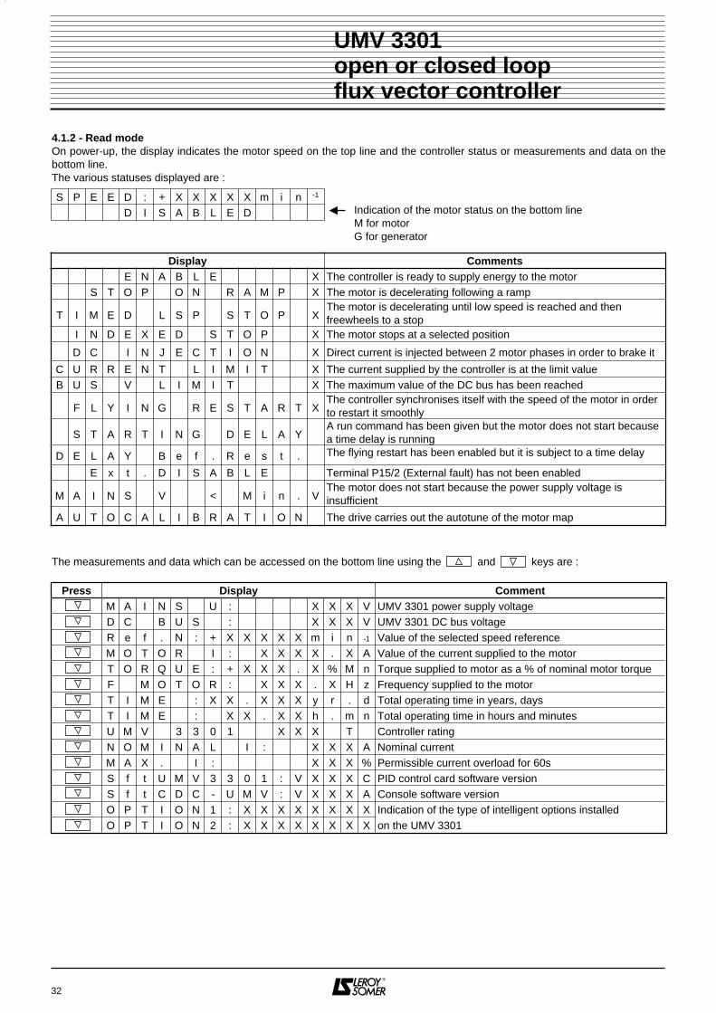
32
UMV 3301open or closed loopflux vector controller
4.1.2 - Read modeOn power-up, the display indicates the motor speed on the top line and the controller status or measurements and data on thebottom line.The various statuses displayed are :
The measurements and data which can be accessed on the bottom line using the and keys are :
S P E E D : + X X X X X m i n -1
D I S A B L E D
Press Display CommentM A I N S U : X X X V UMV 3301 power supply voltageD C B U S : X X X V UMV 3301 DC bus voltageR e f . N : + X X X X X m i n -1 Value of the selected speed referenceM O T O R I : X X X X . X A Value of the current supplied to the motorT O R Q U E : + X X X . X % M n Torque supplied to motor as a % of nominal motor torqueF M O T O R : X X X . X H z Frequency supplied to the motorT I M E : X X . X X X y r . d Total operating time in years, daysT I M E : XXX . X X h . m n Total operating time in hours and minutesU M V 3 3 0 1 X X X T Controller ratingN O M I N A L I : X X X A Nominal currentM A X . I : X X X % Permissible current overload for 60s S f t U M V 3 3 0 1 : V X X X C PID control card software version S f t C D C - U M V : V X X X A Console software versionO P T I O N 1 : X X X X X X X X Indication of the type of intelligent options installedO P T I O N 2 : X X X X X X X X on the UMV 3301
Indication of the motor status on the bottom lineM for motor G for generator
Display CommentsE N A B L E X The controller is ready to supply energy to the motor
S T O P O N R A M P X The motor is decelerating following a ramp
T I M E D L S P S T O P XThe motor is decelerating until low speed is reached and thenfreewheels to a stop
I N D E X E D S T O P X The motor stops at a selected position
D C I N J E C T I O N X Direct current is injected between 2 motor phases in order to brake it
C U R R E N T L I M I T X The current supplied by the controller is at the limit valueB U S V L I M I T X The maximum value of the DC bus has been reached
F L Y I N G R E S T A R T XThe controller synchronises itself with the speed of the motor in orderto restart it smoothly
S T A R T I N G D E L A YA run command has been given but the motor does not start becausea time delay is running
D E L A Y B e f . R e s t . The flying restart has been enabled but it is subject to a time delay
E x t . D I S A B L E Terminal P15/2 (External fault) has not been enabled
M A I N S V < M i n . VThe motor does not start because the power supply voltage isinsufficient
A U T O C A L I B R A T I O N The drive carries out the autotune of the motor map

4.1.3 - Parameter-setting modePressing the MODE key gives access to the parameter-setting mode. The drive is configured for a givenapplication using the parameters which are organisedinto menus, with each menu corresponding to a groupof parameters linked by a function.Numerical or binary parameters can be accessed :- either in " READ WRITE " : R-W, for example : basicfrequency, etc.
4.1.4 - UMV 3301 menus
- or in " READ " : R, for example : motor speed image,etc.-or in " READ ASSIGN " : R-A, for example : selection of1 programmable acceleration, etc.
Note : - When modifying assignments, it is necessary to exit themenu so that the display is updated and indicates theselected assignment.- The settings can be protected by an access code.The parameters are then only accessible in read-onlymode.
33
UMV 3301open or closed loopflux vector controller
Display Function
SELECT. For selecting the language in which the parameters will be displayed.
ACCESS CODE For entering a code to protect access to parameter-setting.DRIVE SYSTEM
CONFIGURATION 01 Adaptation of the controller to the motor and to the application.
PROGRAMMABLEUSER MENU For grouping together the most commonly used parameters.
Menus which provide access to simplified setup
Display FunctionSPEED
REFERENCE 02 Generation and selection of analogue or preset references.ACCEL/DECEL
RAMP 03 Selection of the ramps according to the operating modes.SPEED CURRENT
TORQUE CONTROL 04 Selection of the regulation mode and adjustment of its limits.THRESHOLDS
ALARMS/TIMERS 05 Programming speed, torque, voltage thresholds, which can be assigned to relays or logic outputs.MACHINECONTROL 06 Selection of start and stop modes, brake control and braking resistances.
ANALOGUEINPUTS/OUTPUTS 07 Scaling and assignment of analogue inputs and outputs.
DIGITALINPUTS 08 Assignment, inversion and processing of logic inputs.DIGITAL
OUTPUTS/RELAYS 09 Selection of sources, processing, inversion of logic outputs and relays.DRIVE SYSTEM
STATUS 10 Reading operating states and management of faults.END-USER MENUCONFIGURATION 11 Assignment in the user menu of the parameters most frequently used in the application.PROGRAMMABLE
THRESHOLDS 12 Selection of sources, processing and assignment of programmable threshold functions.SERIAL
LINK 13 Serial link, hour counter and energy counter.P.I.D.
CONTROLLER 14 Adjustment, assignment and processing of the P.I.D. loop.HOISTING
SPECIAL SET-UP 15 Functions specific to a lifting application.REGENERATION
MODE 16 These menus are related with specific applications and are discribed in the associated instructions.INTERNAL
USE 19 Contact LEROY-SOMER for more informations.
Special menus which provide access to specific applications

34
UMV 3301open or closed loopflux vector controller
4.1.5 - Parameter-setting principles
Comment Press DisplayPower-up of the electronics
The display is in Read mode -
Change to parameter-setting modeMODE
Go to the required menu
Eg. : Menu 1
Enter the selected menu
Go to the parameter to be modified
Eg. : Overtorque request 3 x
Modify the parameter by moving the cursor
to the value to be modified
Make the selection
Press several times to display all the choices
Memorise once the choice has been made
The cursor returns to the parameter MEM
Go to another parameter
To modify a numerical parameter place the
cursor on the first number
Use the key to increment or
the key to decrement 2 x
Move the cursor to the number to be modified
Use the key to decrement or the key to increment 5 x
Memorise settingMEM
Exit menu 1
Access all the menus which require
modification of parameters
When parameter-setting is complete, return to
read mode MODE
S P E E D : + 0 0 0 0 0 m i n -1D I S A B L E D
S E L E C T .L A N G U A G E : E N G L I S H
A C C E S S C O D E0 0 0 0
D R I V E S Y S T E MC O N F I G U R A T I O N 0 1
0 1 0 1 C T R L M O D EO P E N L O O P
0 1 0 4 R E Q U E S TO V E R T O R Q . : H I G H
0 1 0 4 R E Q U E S TO V E R T O R Q . : H I G H
0 1 0 4 R E Q U E S TO V E R T O R Q . : L O W
0 1 0 4 R E Q U E S TO V E R T O R Q . : L O W
0 1 2 1 N o m . M o t o rP O W E R : 7 5 , 0 k W
0 1 2 1 N o m . M o t o rP O W E R : 7 5 , 0 k W
0 1 2 1 N o m . M o t o rP O W E R : 9 5 , 0 k W
0 1 2 1 N o m . M o t o rP O W E R : 9 5 , 0 k W
0 1 2 1 N o m . M o t o rP O W E R : 9 0 , 0 k W
0 1 2 1 N o m . M o t o rP O W E R : 9 0 , 0 k W
D R I V E S Y S T E MC O N F I G U R A T I O N 0 1
P R O G R A M M A B L EU S E R M E N U
S P E E D : + 0 0 0 0 m i n -1D I S A B L E D
1
2
3
Note : In parameter-setting mode, if no key on the keypad has been pressed for 3 min, the display automatically returns to readmode.
: The cursor is memorised by flashing of the zone in which it is positioned (shown in grey in the display column).
: The number to the left represents the number of the menu followed by the number of the parameter.
: The key is used to go back if you have gone too far.
1
2
3

4.1.6 - Changing the display language
All displays from now on will be in English
4.1.7 Setting up a security code
4.1.8 - Return to factory settings
35
UMV 3301open or closed loopflux vector controller
Note : Only the Select and access code menus can be accessed. In order to access any other menu, enter the code andmemorise it.
Comment Press DisplayPower up the electronics
The display is in Read mode -
Go to parameter-setting modeMODE
Move the cursor
Select English
Memorise the languageMEM
V i t . : + 0 0 0 0 0 m i n -1V E R R O U I L L E
S E L E C T .L A N G U E : F R A N C A I S E
S E L E C T .L A N G U E : F R A N C A I S E
S E L E C T .L A N G U A G E : E N G L I S H
S E L E C T .L A N G U A G E : E N G L I S H
Comment Press DisplayPower up the electronics
The display is in Read mode -
Go to parameter-setting modeMODE
Select the access code menu
Enter the menu and access the first number of
the code
Modify the first number
Access the second number
Modify it and go to the next one, and so on
Memorise the chosen codeMEM
To validate the code, switch off then switch on-
S P E E D : + 0 0 0 0 0 m i n -1D I S A B L E D
S E L E C T .L A N G U A G E : E N G L I S H
A C C E S C O D E0 0 0 0
A C C E S C O D E0 0 0 0
A C C E S C O D EX 0 0 0
A C C E S C O D EX 0 0 0
D R I V E S Y S T E MC O N F I G U R A T I O N 0 1
S P E E D : + 0 0 0 0 0 m i n -1D I S A B L E D
Comment Press DisplayWith the controller off, press all 4 keys simultaneouslythen power up
, ,
and
Validate the returnMEM
All parameters, except those in menu 1, have
returned to their original value -
B A C K T O F A C T O R YS e t t g s Y E S > > M E M
B A C K T O F A C T O R YS e t t g s > W A I T . . .
S P E E D : + X X X X X m i n -1D I S A B L E D
Note : The return to factory settings also cancels the current security code.

4.2 - Simplified setup4.2.1 - Programming• Power up the electronics supply by closing QF.
• Select menu 1 : (described in section 4.3) and set thecontroller, motor and application parameters.
• Select the user menu : (described in section 4.4) Set the parameters of the user menu according to theoperation (references, run commands, limits, etc).
4.2.2 - Dynamic tests• Starting :- activate the power contactor,- select forward or reverse,- apply a reference equal to 10 % of the maximumreference,- check the direction of rotation and speed of the motor,- give a stop command.
• Optimising the settings :- Adjust the acceleration (03.10) and deceleration (03.30)ramps and make abrupt changes to the reference (closeto maximum speed),- observe the increase in motor speed,- increase the stability only if the driven inertia is veryhigh.
36
UMV 3301open or closed loopflux vector controller
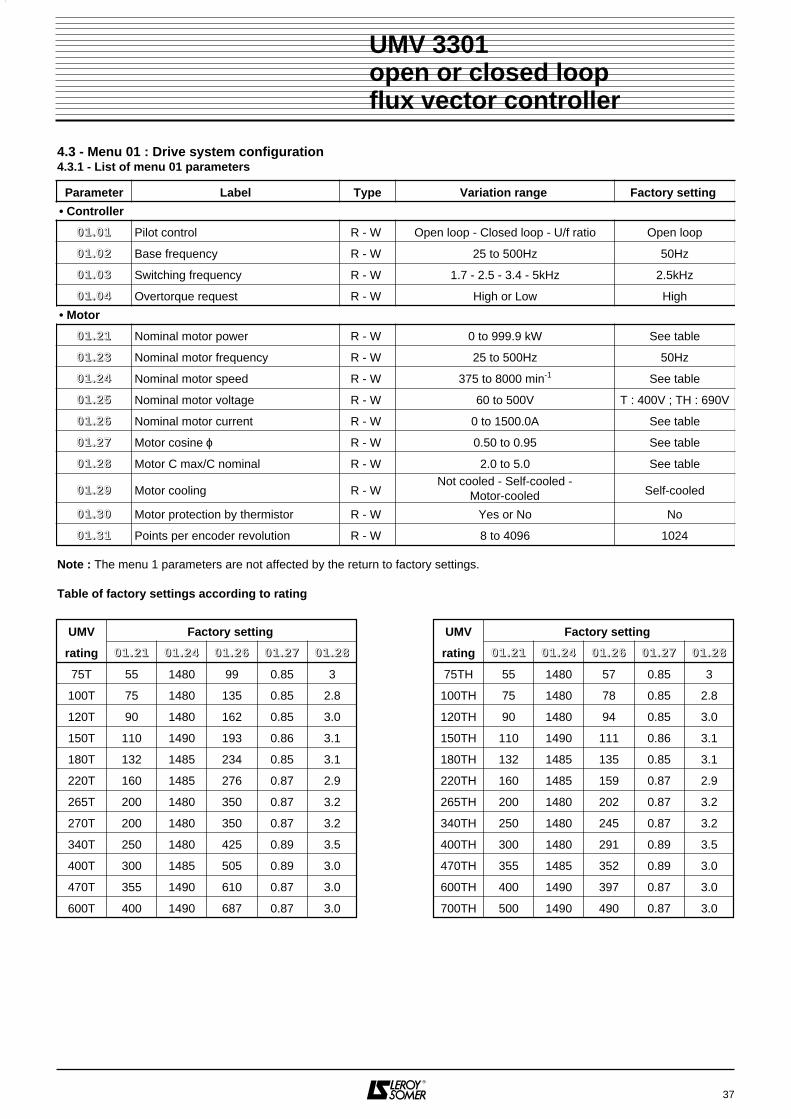
37
UMV 3301open or closed loopflux vector controller
4.3 - Menu 01 : Drive system configuration4.3.1 - List of menu 01 parameters
Parameter Label Type Variation range Factory setting
• Controller
00 11 .. 00 11 Pilot control R - W Open loop - Closed loop - U/f ratio Open loop
00 11 .. 00 22 Base frequency R - W 25 to 500Hz 50Hz
00 11 .. 00 33 Switching frequency R - W 1.7 - 2.5 - 3.4 - 5kHz 2.5kHz
00 11 .. 00 44 Overtorque request R - W High or Low High
• Motor
00 11 .. 22 11 Nominal motor power R - W 0 to 999.9 kW See table
00 11 .. 22 33 Nominal motor frequency R - W 25 to 500Hz 50Hz
00 11 .. 22 44 Nominal motor speed R - W 375 to 8000 min-1 See table
00 11 .. 22 55 Nominal motor voltage R - W 60 to 500V T : 400V ; TH : 690V
00 11 .. 22 66 Nominal motor current R - W 0 to 1500.0A See table
00 11 .. 22 77 Motor cosine ϕ R - W 0.50 to 0.95 See table
00 11 .. 22 88 Motor C max/C nominal R - W 2.0 to 5.0 See table
00 11 .. 22 99 Motor cooling R - W Not cooled - Self-cooled -
Motor-cooled Self-cooled
00 11 .. 33 00 Motor protection by thermistor R - W Yes or No No
00 11 .. 33 11 Points per encoder revolution R - W 8 to 4096 1024
Note : The menu 1 parameters are not affected by the return to factory settings.
Table of factory settings according to rating
UMV Factory setting
rating 00 11 .. 22 11 00 11 .. 22 44 00 11 .. 22 66 00 11 .. 22 77 00 11 .. 22 88
75T 55 1480 99 0.85 3
100T 75 1480 135 0.85 2.8
120T 90 1480 162 0.85 3.0
150T 110 1490 193 0.86 3.1
180T 132 1485 234 0.85 3.1
220T 160 1485 276 0.87 2.9
265T 200 1480 350 0.87 3.2
270T 200 1480 350 0.87 3.2
340T 250 1480 425 0.89 3.5
400T 300 1485 505 0.89 3.0
470T 355 1490 610 0.87 3.0
600T 400 1490 687 0.87 3.0
UMV Factory setting
rating 00 11 .. 22 11 00 11 .. 22 44 00 11 .. 22 66 00 11 .. 22 77 00 11 .. 22 88
75TH 55 1480 57 0.85 3
100TH 75 1480 78 0.85 2.8
120TH 90 1480 94 0.85 3.0
150TH 110 1490 111 0.86 3.1
180TH 132 1485 135 0.85 3.1
220TH 160 1485 159 0.87 2.9
265TH 200 1480 202 0.87 3.2
340TH 250 1480 245 0.87 3.2
400TH 300 1480 291 0.89 3.5
470TH 355 1485 352 0.89 3.0
600TH 400 1490 397 0.87 3.0
700TH 500 1490 490 0.87 3.0

4.3.2 - Menu 01 parameters
: Pilot controlRange : Open loop, Closed loop, U/F ratioFactory setting : Open loopSelection of controller operating mode according to theapplication and the options used.• Open loop : operation as a flux vector controllerwithout feedback, used for the majority of applica-tions.• Closed loop : operation as a flux vector controller withfeedback. If the motor has an optional encoder, state thisin 00 11 .. 33 11. If the motor has an optional resolver, thecontroller must be fitted with a resolver option card (notcurrently available).• U/F ratio: operation as a frequency inverter, the regulatedmeasurement being the output frequency of the controller.Used when open loop vector control is not suitable, forexample, when supplying several motors of differentpowers which are not mechanically linked, or supplying amedium voltage motor via a transformer.
: Base frequencyRange : 25 to 500 HzFactory setting : 50 HzThis is the frequency for which the output voltage of thecontroller reaches the nominal motor value declared in00 11 .. 22 55.V/F motor characteristics in open lopp
For a non-specific application, set the frequencyindicated on the motor nameplate.
: Switching frequencyRange : 1.7 - 2.5 - 3.4 or 5 kHzFactory setting : 2.5 kHzFrequency for generating PWM pulses. A high frequencyreduces the noise in the motor but increases thetemperature rise of the controller power modules and thelevel of interference.
: Overtorque requestRange : High or LowFactory setting : HighAccording to the application and the required torque,adjustment of overload characteristics.• High : maximum overload with continuous nominalcurrent indicated on nameplate. Applications : grind-er, press, extruder, high inertias, etc.• Low : reduced overload with increased continuousnominal current. Applications : pomp, cooling, etc.
38
UMV 3301open or closed loopflux vector controller
00 11 .. 00 11
00 11 .. 00 22
00 11 .. 00 33
00 11 .. 00 44
UMV 3301 00 11 .. 00 44 = LOWrating I max (A) Overload (% In)75T 145 125
100T 180 120120T 220 116150T 260 112180T 315 114220T 380 115265T 480 118270T 490 118340T 580 115400T 680 114470T 820 117600T 970 115
UMV 3301 00 11 .. 00 44 = HIGHrating I max (A) Overload (% In)75T 112 155
100T 145 150120T 180 142150T 220 132180T 260 138220T 315 139265T 380 149270T 380 149340T 480 140400T 580 134470T 680 135600T 860 128
UMV 3301 00 11 .. 00 44 = LOWrating I max (A) Overload (% In)75TH 85 112
100TH 115 112120TH 135 112150TH 155 112180TH 190 112220TH 225 112265TH 280 110340TH 340 109400TH 400 110470TH 450 109600TH 580 110700TH 670 109
UMV 3301 00 11 .. 00 44 = HIGHrating I max (A) Overload (% In)75TH 63 150
100TH 86 150120TH 101 150150TH 116 150180TH 142 150220TH 165 150265TH 205 150340TH 255 146400TH 300 147470TH 350 140600TH 450 142700TH 500 146
Motorvoltage
Motorfrequency
01.25
01.0
2<
01.2
3
01.02
=01
.23
01.02 > 01.23
01.23
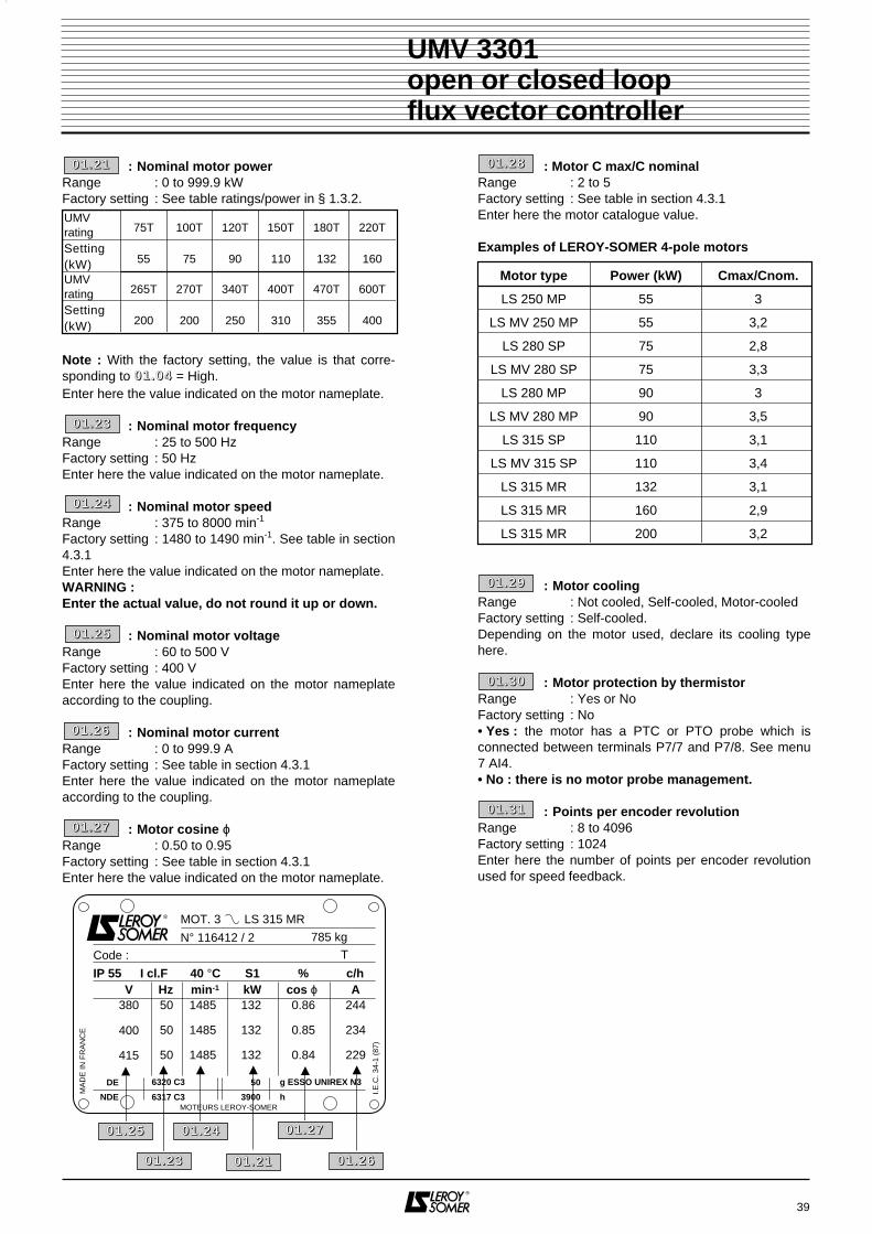
: Nominal motor powerRange : 0 to 999.9 kWFactory setting : See table ratings/power in § 1.3.2.
Note : With the factory setting, the value is that corre-sponding to 00 11 .. 00 44 = High.Enter here the value indicated on the motor nameplate.
: Nominal motor frequencyRange : 25 to 500 HzFactory setting : 50 HzEnter here the value indicated on the motor nameplate.
: Nominal motor speedRange : 375 to 8000 min-1
Factory setting : 1480 to 1490 min-1. See table in section4.3.1Enter here the value indicated on the motor nameplate.WARNING :Enter the actual value, do not round it up or down.
: Nominal motor voltageRange : 60 to 500 VFactory setting : 400 VEnter here the value indicated on the motor nameplateaccording to the coupling.
: Nominal motor currentRange : 0 to 999.9 AFactory setting : See table in section 4.3.1Enter here the value indicated on the motor nameplateaccording to the coupling.
: Motor cosine ϕRange : 0.50 to 0.95Factory setting : See table in section 4.3.1Enter here the value indicated on the motor nameplate.
: Motor C max/C nominalRange : 2 to 5Factory setting : See table in section 4.3.1Enter here the motor catalogue value.
Examples of LEROY-SOMER 4-pole motors
: Motor coolingRange : Not cooled, Self-cooled, Motor-cooledFactory setting : Self-cooled.Depending on the motor used, declare its cooling typehere.
: Motor protection by thermistorRange : Yes or NoFactory setting : No• Yes : the motor has a PTC or PTO probe which isconnected between terminals P7/7 and P7/8. See menu7 AI4.• No : there is no motor probe management.
: Points per encoder revolutionRange : 8 to 4096Factory setting : 1024Enter here the number of points per encoder revolutionused for speed feedback.
39
UMV 3301open or closed loopflux vector controller
MOT. 3 LS 315 MR
N° 116412 / 2 785 kg
TCode :
IP 55 I cl.F 40 °C S1 % c/hHzV min-1 kW cos ϕ A
380
400
415
50
50
50
1485
1485
1485
132
132
132
0.86
0.85
0.84
244
234
229
DE 6320 C3
6317 C3
g ESSO UNIREX N3
hNDE
50
3900MOTEURS LEROY-SOMER
MA
DE
IN F
RA
NC
E
I.E.C
. 34-
1 (8
7)
Motor type Power (kW) Cmax/Cnom.
LS 250 MP 55 3
LS MV 250 MP 55 3,2
LS 280 SP 75 2,8
LS MV 280 SP 75 3,3
LS 280 MP 90 3
LS MV 280 MP 90 3,5
LS 315 SP 110 3,1
LS MV 315 SP 110 3,4
LS 315 MR 132 3,1
LS 315 MR 160 2,9
LS 315 MR 200 3,2
00 11 .. 22 66
00 11 .. 22 77
00 11 .. 22 7700 11 .. 22 4400 11 .. 22 55
00 11 .. 22 6600 11 .. 22 1100 11 .. 22 33
00 11 .. 22 88
00 11 .. 22 99
00 11 .. 33 00
00 11 .. 33 11
00 11 .. 22 11
00 11 .. 22 33
00 11 .. 22 44
00 11 .. 22 55
UMVrating 75T 100T 120T 150T 180T 220T
Setting(kW) 55 75 90 110 132 160
UMVrating 265T 270T 340T 400T 470T 600T
Setting(kW) 200 200 250 310 355 400

40
UMV 3301open or closed loopflux vector controller
NOTES

41
UMV 3301open or closed loopflux vector controller
4.4 - User menu4.4.1 - List of user menu parameters
Parameter Label Type Variation range Factory setting
00 22 .. 55 00 CDC - UMV speed reference R - W ± 8000min-1 0
00 22 .. 00 22 Speed reference source R - W Terminal block, CDC - UMV Terminal block
00 66 .. 00 11 Control source R - W Terminal block, CDC - UMV, RS 485 Terminal block
00 66 .. 00 33 Starting R - W Controlled or Automatic Controlled
11 00 .. 00 22 Reset R - W Controlled or Automatic Controlled
00 66 .. 00 55 Flying restart R - W Yes or No No
11 00 .. 00 66 Mains undervoltage threshold R - W 240V to 320V 300V
11 00 .. 00 77 Mains time delay R - W 0 to 20.00s 0.50s
00 77 .. 11 77 AI1 100 % calibration R - W 0 to 8000 1500
00 77 .. 33 66 AI3 reference selection R - W 0/10V, 0/20mA, 4/20mA 4/20mA
00 77 .. 33 33 AI3 0 % calibration R - W 0 to 8000 0
00 77 .. 33 44 AI3 100 % calibration R - W 0 to 8000 1500
00 22 .. 22 11 Speed reference PS1 R - W ± 8000min-1 1500 min-1
00 22 .. 22 22 Speed reference PS2 R - W ± 8000min-1 1000 min-1
00 22 .. 22 33 Speed reference PS3 R - W ± 8000min-1 750 min-1
00 22 .. 88 11 Minimum limit (clockwise) R - W 0 to 8000min-1 0
00 22 .. 88 33 Maximum limit (clockwise) R - W 0 to 8000min-1 1500 min-1
00 22 .. 99 11 Skip speed 1 R - W ± 8000min-1 0
00 22 .. 99 44 Skip band 1 R - W 0 to 255min-1 0
00 22 .. 77 00 Forward/Reverse R - W Disabled or Enabled Enabled
00 33 .. 11 00 Main acceleration ramp 1 R - W 0.1 to 3200s 20s
00 33 .. 33 00 Main deceleration ramp 3 R - W 0.1 to 3200s 20s
00 77 .. 22 99 AI2 destination R - W None - 00 44 .. 33 66 (1) None
00 77 .. 22 77 AI2 100 % calibration R - W 0 to 8000 100
00 44 .. 33 66 Motor torque limit 2 R - W 0 to 300% Mn 110 % Mn
00 55 .. 11 22 Alarm 1 threshold R - W 0 to 9999 0
00 55 .. 22 22 Alarm 2 threshold R - W 0 to 9999 1500
00 77 .. 55 22 AO1 type selection R - W 0/10V, 0/20mA, 4/20mA 4/20mA
00 77 .. 55 77 AO1 100 % calibration R - W 0 to 8000 150
00 77 .. 66 22 AO2 type selection R - W 0/10V, 0/20mA, 4/20mA 4/20mA
00 77 .. 66 77 AO2 100 % calibration R - W 0 to 8000 1800
00 44 .. 00 44 Stability R - W 0.1 to 40 4.0
(1) There are other possible assignments for 00 77 .. 22 99 but only the assignment of 00 44 .. 33 66 (torque limiting) is operational when us-ing the user menu.
Note : Depending on the application, the parameters in this menu may be replaced by parameters more suited to theapplication. Simply assign them in menu 11.
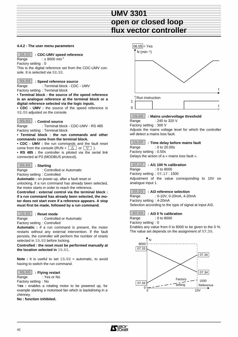
4.4.2 - The user menu parameters
: CDC-UMV speed referenceRange : ± 8000 min-1
Factory setting : 0This is the digital reference set from the CDC-UMV con-sole. It is selected via 00 22 .. 00 22.
: Speed reference sourceRange : Terminal block - CDC - UMVFactory setting : Terminal block• Terminal block : the source of the speed referenceis an analogue reference at the terminal block or adigital reference selected via the logic inputs.• CDC - UMV : the source of the speed reference is00 22 .. 55 00 adjusted on the console.
: Control sourceRange : Terminal block - CDC-UMV - RS 485Factory setting : Terminal block• Terminal block : the run commands and othercommands come from the terminal block.• CDC - UMV : the run commands and the fault resetcome from the console (RUN + or ).• RS 485 : the controller is piloted via the serial linkconnected at P3 (MODBUS protocol).
: StartingRange : Controlled or AutomaticFactory setting : ControlledAutomatic : on power-up, after a fault reset or unlocking, if a run command has already been selected,the motor starts in order to reach the reference.Controlled : external control via the terminal block :if a run command has already been selected, the mo-tor does not start even if a reference appears. A stopmust first be made, followed by a run command.
: Reset modeRange : Controlled or AutomaticFactory setting : ControlledAutomatic : if a run command is present, the motorrestarts without any external intervention. If the faultpersists, the controller will perform the number of resetsselected in 11 00 .. 00 33 before locking.Controlled : the reset must be performed manually atthe location selected in 11 00 .. 00 11.
Note : It is useful to set 11 00 .. 00 22 = automatic, to avoidhaving to switch the run command.
: Flying restartRange : Yes or NoFactory setting : NoYes : enables a rotating motor to be powered up, forexample starting a motorised fan which is backdriving in achimney.No : function inhibited.
42
UMV 3301open or closed loopflux vector controller
: Mains undervoltage thresholdRange : 240 to 320 VFactory setting : 300 VAdjusts the mains voltage level for which the controllerwill detect a mains loss fault.
: Time delay before mains faultRange : 0 to 20.00sFactory setting : 0.50sDelays the action of a « mains loss fault ».
: AI1 100 % calibrationRange : 0 to 8000Factory setting : 00 77 .. 11 77 : 1500Adjustment of the value corresponding to 10V onanalogue input 1.
: AI3 reference selectionRange : 0-10V, 0-20mA, 4-20mAFactory setting : 4-20mASelection according to the type of signal at input AI3.
: AI3 0 % calibrationRange : 0 to 8000Factory setting : 0Enables any value from 0 to 8000 to be given to the 0 %.The value set depends on the assignment of 00 77 .. 33 99.
N (min )-1
t
t1
0
06.05 = Yes
Run instruction
N
07.331500
07.34
07.34
07.338000
00 10V
Reference
Factory
setting
00 22 .. 55 00
00 22 .. 00 22
00 66 .. 00 11
00 66 .. 00 33
11 00 .. 00 22
00 66 .. 00 55
11 00 .. 00 66
11 00 .. 00 77
00 77 .. 11 77
00 77 .. 33 66
00 77 .. 33 33

: AI3 100 % calibrationRange : 0 to 8000Factory setting : 1500Enables any value from 0 to 8000 to be given to the 10V.The value set depends on the assignment of 00 77 .. 33 99.
to : Speed references PS1 to PS3Range : ± 8000 min-1
Factory settings : 00 22 .. 22 11 = 1500 min-1
00 22 .. 22 22 = 1000 min-1
00 22 .. 22 33 = 750 min-1
Preset speeds 1 to 3 (00 22 .. 22 11 to 00 22 .. 22 33) can be accessedvia combinations of logic inputs DI1 and DI2.Selection
: Min limitRange : 0 to + 8000 min-1
Factory setting : 0This is the lowest reference for clockwise or anti-clockwise operation. 00 22 .. 00 11 cannot have a value below00 22 .. 88 11.
: Max limitRange : 0 to + 8000 min-1
Factory setting : 1500 min-1
This parameter sets the highest reference for clockwiseor anti-clockwise operation. 00 22 .. 00 11 cannot have a valueabove 00 22 .. 88 33.
: Speed : skips 1Range : ± 8000 min-1
Factory setting : 0This parameter enables the system to skip 1 speedwhich causes operational problems (noise, vibrations,resonance). Skip point 1 is set via 00 22 .. 99 11. It affects thespeed increase and decrease.
: Skip band 1Range : 0 to 255 min-1
Factory setting : 0Point 00 22 .. 99 11 has an associated total skip band set via0022..9944. One speed zone can therefore be avoided duringoperation. Note : the skip speed is at a central point in the skip band.
: Forward/ReverseRange : Disabled or EnabledFactory setting : EnabledDisabled : reversal of the direction of rotation of the mo-tor is prohibited, even if the reference polarities are in-verted, and whatever the control mode (external via theterminal block, serial link, console).Enabled : the motor can turn in both directions.
43
UMV 3301open or closed loopflux vector controller
and : Main ramps 1 and 3Range : 0.1 to 3200sFactory setting : 20sThis is the acceleration 00 33 .. 11 00 or deceleration 00 33 .. 33 00time for 1000 min-1.
: AI2 destinationRange : None - Torque limitingFactory setting : NoneSelects the destination of analogue input AI2.
: AI2 100 % calibrationRange : 0 to 8000Factory setting : 100Adjustment of the value corresponding to 10V on theanalogue input.
: Motor torque limit 2Range : 0 to 300 % InFactory setting : 110 % MnThis is the continuous max torque supplied in motor mode.If 00 44 .. 33 88 = yes, 00 44 .. 33 77 = 04.36.
: Alarm 1 threshold Range : 0 to 9999Factory setting : 0Sets the underspeed threshold, assigned to relay RL1.
: Alarm 2 thresholdRange : 0 to 9999Factory setting : 1500Sets the overspeed threshold, assigned to output DO3.
and : AO1 - AO2 type selectionRange : 0 - 10V, 4 - 20mA, 0- 20mAFactory setting : 4 - 20mASelection of the signal supplied by the analogue output.Note : The 4-20mA and 0-20mA signals can be invertedvia 00 77 .. 55 11 and 00 77 .. 66 11.
and : AO1 - AO2 100 % calibrationRange : 0 to 8000Factory setting : AO1 = 150, AO2 = 1800Scaling of the signal selected via the source 0077..5599 or0077..6699. With the factory setting, output AO1 is assigned tothe current image, and output AO2 is assigned to the speedimage.
: StabilityRange : 0.1 to 40.0Factory setting : 4This parameter is used to set the speed stability.The factory setting is suitable for most applications.It can be increased for high inertias.
DI1 DI2 DI4 Reference0 0 0 AI1+0 0 1 AI30 1 0 or 1 PS21 0 0 or 1 PS11 1 0 or 1 PS3
00 77 .. 33 44
00 22 .. 22 11 00 22 .. 22 33
00 33 .. 11 00 00 33 .. 33 00
00 77 .. 22 99
00 22 .. 88 11
00 77 .. 22 77
00 44 .. 33 66
00 55 .. 11 22
00 55 .. 22 22
00 77 .. 55 22 00 77 .. 66 22
00 77 .. 55 77 00 77 .. 66 77
00 44 .. 00 44
00 22 .. 88 33
00 22 .. 99 11
00 22 .. 99 44
00 22 .. 77 00

4.4.3 - User menu block diagram (1)
44
UMV 3301open or closed loopflux vector controller
AI1
+S
peed
refe
renc
e 0
- 10
V
DI4Spe
ed r
efer
ence
sel
ectio
n
AI3
Spe
edre
fere
nce
4 -
20m
A
0
0
1
1
0 10 1
0 1
02.2
1
Con
vers
ion
to 0
- 1
0V
PS
1
DI1
DI2
02.2
2P
S2
02.2
3P
S3
CD
C-U
MV
refe
renc
e
02.1
0
02.0
2S
peed
sour
ce
Rea
dR
efer
ence
befo
relim
its
Imag
e of
spee
dre
fere
nce
02.1
6
02.5
0
Ana
logu
esp
eed
refe
renc
e
07.1
7
010
V
07.3
4
07.3
6
07.3
3
420
mA
02.8
0
RE
V
0
1
02.8
1
02.8
1
Sto
p if
RE
V a
nd F
WD
enab
led
sim
ulta
neou
sly
X(-
1)02
.83
02.8
3
Spe
ed li
mits
FW
D
= 1
Max
Max
Min
Min
02.9
4
02.9
1S
kip
spee
d
Ski
p ba
nd
X(-
1)
= 1
Rea
d/w
rite
Rea
d-on
ly
Rea
d an
d as
sign
Logi
c in
vers
ion
Exc
lusi
ve O
R fu
nctio
n
&Lo
gic
AN
D fu
nctio
n
0/10
V0/
20m
A4/
20m
A

4.4.3 - User menu block diagram (2)
45
UMV 3301open or closed loopflux vector controller
01
Spe
ed
refe
renc
ebe
fore
ram
p
For
war
d/R
ever
se
Mai
nra
mp
1ac
cele
ratio
n
Mai
n ra
mp
3de
cele
ratio
n
0
01
1
03.1
0
Lock
ram
p
04.3
6
02.7
0
Aut
omat
ic
Con
trol
ledA
I2 d
estin
atio
n
07.2
9
02.0
103
.02
Spe
ed r
efer
ence
afte
r ra
mp
03.3
0
06.0
3
05.1
2
Sta
rt
Fly
ing
rest
art
Com
man
d so
urce
Res
et
Tor
que
limiti
ng
Non
e
Dyn
amic
sp
eed
loop
Ope
ratin
g m
ode
Lock
ram
pF
reew
heel
sto
p
Ena
bled
Dis
able
d
CD
C U
MV
Ter
min
al b
lock
RS
485
Aut
omat
ic
Con
trol
led
0 1K
0
4.04
I
Mot
orco
ntro
l
Sta
bilit
y Logi
c ou
tput
con
figur
atio
n
RL1
: M
in. s
peed
thre
shol
d
RL2
: U
MV
out
put a
ctiv
e
DO
1 : C
urre
nt li
mit
reac
hed
DO
2 : U
MV
faul
t
DO
3 : M
ax. s
peed
thre
shol
d06
.05
06.0
1
10.0
2
X(-
1)
= 1
Rea
d/w
rite
Rea
d-on
ly
Rea
d an
d as
sign
Logi
c in
vers
ion
Exc
lusi
ve O
R fu
nctio
n
&Lo
gic
AN
D fu
nctio
n
07.2
7
010
V
Tor
que
limiti
ng 0
- 1
0V
03.0
7
05.2
2
07.5
2
07.5
7
07.6
2
07.6
7
Ana
logu
e ou
tput
con
figur
atio
n
AO
1 : C
urre
nt im
age
- T
ype
of s
igna
l
- S
calin
g
AO
2 : S
peed
imag
e
- T
ype
of s
igna
l
- S
calin
g
DI5
AI2
DI3

46
UMV 3301open or closed loopflux vector controller
NOTES
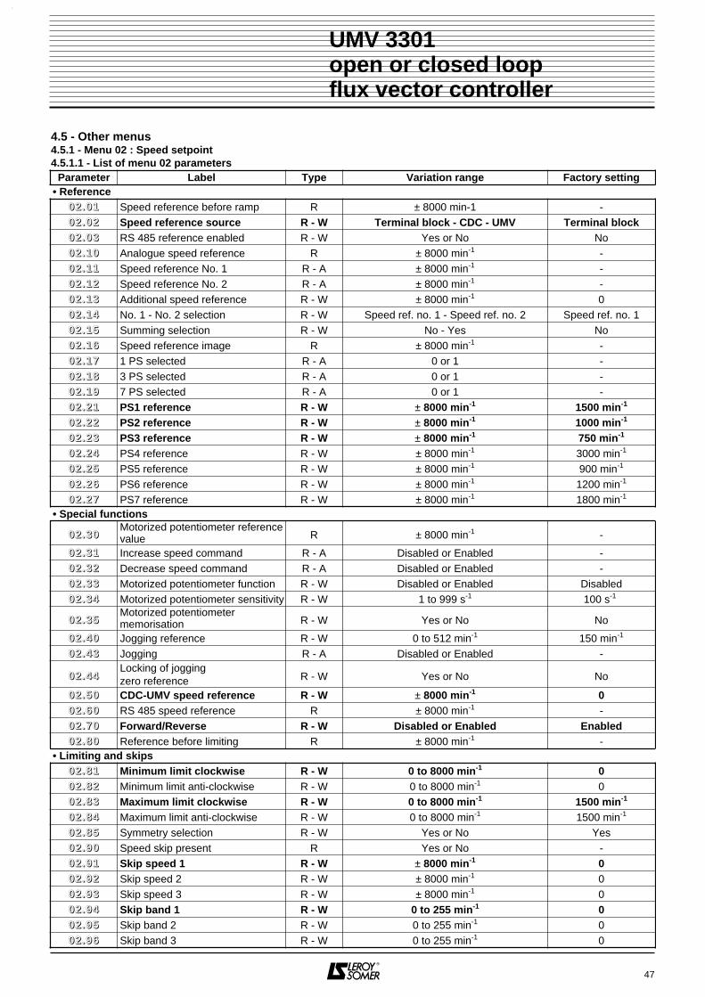
47
UMV 3301open or closed loopflux vector controller
4.5 - Other menus4.5.1 - Menu 02 : Speed setpoint4.5.1.1 - List of menu 02 parameters
Parameter Label Type Variation range Factory setting• Reference
00 22 .. 00 11 Speed reference before ramp R ± 8000 min-1 -00 22 .. 00 22 Speed reference source R - W Terminal block - CDC - UMV Terminal block00 22 .. 00 33 RS 485 reference enabled R - W Yes or No No00 22 .. 11 00 Analogue speed reference R ± 8000 min-1 -00 22 .. 11 11 Speed reference No. 1 R - A ± 8000 min-1 -00 22 .. 11 22 Speed reference No. 2 R - A ± 8000 min-1 -00 22 .. 11 33 Additional speed reference R - W ± 8000 min-1 000 22 .. 11 44 No. 1 - No. 2 selection R - W Speed ref. no. 1 - Speed ref. no. 2 Speed ref. no. 100 22 .. 11 55 Summing selection R - W No - Yes No00 22 .. 11 66 Speed reference image R ± 8000 min-1 -00 22 .. 11 77 1 PS selected R - A 0 or 1 -00 22 .. 11 88 3 PS selected R - A 0 or 1 -00 22 .. 11 99 7 PS selected R - A 0 or 1 -00 22 .. 22 11 PS1 reference R - W ± 8000 min-1 1500 min-1
00 22 .. 22 22 PS2 reference R - W ± 8000 min-1 1000 min-1
00 22 .. 22 33 PS3 reference R - W ± 8000 min-1 750 min-1
00 22 .. 22 44 PS4 reference R - W ± 8000 min-1 3000 min-1
00 22 .. 22 55 PS5 reference R - W ± 8000 min-1 900 min-1
00 22 .. 22 66 PS6 reference R - W ± 8000 min-1 1200 min-1
00 22 .. 22 77 PS7 reference R - W ± 8000 min-1 1800 min-1
• Special functions
00 22 .. 33 00Motorized potentiometer referencevalue R ± 8000 min-1 -
00 22 .. 33 11 Increase speed command R - A Disabled or Enabled -00 22 .. 33 22 Decrease speed command R - A Disabled or Enabled -00 22 .. 33 33 Motorized potentiometer function R - W Disabled or Enabled Disabled00 22 .. 33 44 Motorized potentiometer sensitivity R - W 1 to 999 s-1 100 s-1
00 22 .. 33 55Motorized potentiometermemorisation R - W Yes or No No
00 22 .. 44 00 Jogging reference R - W 0 to 512 min-1 150 min-1
00 22 .. 44 33 Jogging R - A Disabled or Enabled -
00 22 .. 44 44Locking of joggingzero reference R - W Yes or No No
00 22 .. 55 00 CDC-UMV speed reference R - W ± 8000 min-1 000 22 .. 66 00 RS 485 speed reference R ± 8000 min-1 -00 22 .. 77 00 Forward/Reverse R - W Disabled or Enabled Enabled00 22 .. 88 00 Reference before limiting R ± 8000 min-1 -
• Limiting and skips00 22 .. 88 11 Minimum limit clockwise R - W 0 to 8000 min-1 000 22 .. 88 22 Minimum limit anti-clockwise R - W 0 to 8000 min-1 000 22 .. 88 33 Maximum limit clockwise R - W 0 to 8000 min-1 1500 min-1
00 22 .. 88 44 Maximum limit anti-clockwise R - W 0 to 8000 min-1 1500 min-1
00 22 .. 88 55 Symmetry selection R - W Yes or No Yes00 22 .. 99 00 Speed skip present R Yes or No -00 22 .. 99 11 Skip speed 1 R - W ± 8000 min-1 000 22 .. 99 22 Skip speed 2 R - W ± 8000 min-1 000 22 .. 99 33 Skip speed 3 R - W ± 8000 min-1 000 22 .. 99 44 Skip band 1 R - W 0 to 255 min-1 000 22 .. 99 55 Skip band 2 R - W 0 to 255 min-1 000 22 .. 99 66 Skip band 3 R - W 0 to 255 min-1 0

4.5.1.2 - The menu 02 parameters
: Speed reference before ramp
Range : ± 8000 min-1
Reads the final speed reference before the ramp.
: Speed reference sourceRange : Terminal block - CDC - UMVFactory setting : Terminal block• Terminal block : the source of the speed referenceis an analogue reference on the terminal block or adigital reference selected via the logic inputs.• CDC - UMV : the source of the speed reference is00 22 .. 55 00 adjusted on the console.
: RS 485 reference enabledRange : Yes or NoFactory setting : NoYes : the serial link produces the reference (0022..6600).No : the reference is selected on the terminal block orthe CDC-UMV.
: Analogue speed reference
Range : ± 8000 min-1.
Reading of the main reference after selection of referenceN1/reference N2 optionally increased by the additionalreference.Note : If 00 22 .. 77 00 = disabled, a negative reference isinhibited.
: Speed reference No. 1Range : ± 8000 min-1
Reading of main reference 1.
: Speed reference No. 2Range : ± 8000 min-1
Reading of main reference 2.
: Additional speed referenceRange : ± 8000 min-1
Factory setting : 0This is a reference which may be added to main referenceN1 or N2. It can be set directly via the console keypad orexternally by assignment to an analogue input.
: No. 1 - No. 2 selectionRange : Speed ref. No. 1 - Speed ref No. 2Factory setting : Speed ref No. 1Choice between reference N1 and reference N2.
: Summing selectionRange : Yes or NoFactory setting : NoYes : references N1 or N2 are increased by the value ofadditional reference 00 22 .. 11 33.No : the additional reference 00 22 .. 11 33 is inhibited.
: Speed reference image
Range : ± 8000 min-1
Reads the main reference or the programmable referencesin min-1
according to the selections made.
: 1 PS selectedRange : 0 or 1Reads the 1 PS selection.0 : 1 PS not controlled.1 : 1 PS controlled.See the binary combinations in 00 22 .. 11 99.
: 3 PS selectedRange : 0 or 1Reads the 3 PS selection.0 : 3 PS not controlled.1 : 3 PS controlled.See the binary combinations in 00 22 .. 11 99.The change of state controlled externally by assignmentand combinations of logic inputs.
: 7 PS selectedRange : 0 or 1Reads the 7 PS selection.0 : 7 PS not controlled.1 : 7 PS controlled.
Binary combinationsThe change of state is controlled externally byassignment and combinations of logic inputs.
to : Speed references PS1 to PS7Range : ± 8000 min-1
Factory settings : 1500 min-1, 1000 min-1, 750 min-1, 3000 min-1, 900 min-1, 1200 min-1, 1800 min-1 respectively
Preset speeds 1 to 7 (00 22 .. 22 11 to 00 22 .. 22 77) can be accessedvia combinations of logic inputs assigned as shown in00 22 .. 11 99.Selection of preset speeds
48
UMV 3301open or closed loopflux vector controller
00 22 .. 11 77 00 22 .. 11 88 00 22 .. 11 99 PS
0 0 0 —
1 0 0 1 (00 22 .. 22 11)
1 1 0 3 (00 22 .. 22 33)
0 1 0 2 (00 22 .. 22 22)
0 0 1 4 (00 22 .. 22 44)
0 1 1 6 (00 22 .. 22 66)
1 0 1 5 (00 22 .. 22 55)
1 1 1 7 (00 22 .. 22 77)
PS102.21
PS202.22
PS302.23
PS402.24
PS502.25
PS602.26
PS702.27
PS202.22
02.17
02.18
02.19
1 0 1 0 1 0 1 0
0 1 1 0 0 1 1 1
0 0 0 1 1 1 1 0
t
n
00 22 .. 00 11
00 22 .. 00 2200 22 .. 11 77
00 22 .. 00 33
00 22 .. 11 00
00 22 .. 11 11
00 22 .. 11 22
00 22 .. 11 33
00 22 .. 11 44
00 22 .. 11 55
00 22 .. 22 11 00 22 .. 22 77
00 22 .. 11 88
00 22 .. 11 99
00 22 .. 11 66

: Motorized potentiometer reference value
Range : ± 8000 min-1
Reads the reference from a command via motorized po-tentiometer.
and : Motorized potentiometercommand
Range : Disabled or Enabled00 22 .. 33 11 : increase speed command.00 22 .. 33 22 : decrease speed command.
: Motorized potentiometer functionRange : Disabled or EnabledFactory setting : DisabledEnabled : the speed reference (00 22 .. 33 00) is increased(00 22 .. 33 11) or decreased (00 22 .. 33 22). The sensitivity of the in-crease/decrease commands is controlled by applying aramp rate (00 22 .. 33 44) to the reference.Disabled : the speed reference is issued from thepreset speeds or from 00 22 .. 11 00.
WARNING :The increase speed command increases the speed :- with the sign of the selected speed for presetspeeds,- with a positive value only for an analogue reference.the decrease speed command decreases the abso-lute speed value.
: Motorized potentiometer sensitivityRange : 1 to 999 s-1
Factory setting : 100 s-1
Adjusts the ramp rate when pressing the increase/de-crease control buttons.
: Motorized potentiometer memorisationRange : Yes or NoFactory setting : NoYes : enables the reference to be retained during a stop,and to return to it at a restart.No : at a stop command the reference will restartfrom 0.
: Jogging referenceRange : 0 to 512 min-1
Factory setting : 150 min-1
The jogging reference is adjusted via 0022..4400 and is al-ways positive. Reversal is made by the REV input whichinverts the reference.
: JoggingRange : Disabled or EnabledEnabled : the speed reference is 00 22 .. 44 00.Disabled : the speed reference is the result of faster/slow-er, preset speeds or 00 22 .. 11 00.
: Locking of jogging zero referenceRange : Yes or NoFactory setting : NoYes : it is not possible to give a jogging reference if0022 .. 3300 or 0022 .. 1166 are other than 0.No : a jogging reference can be given at any time.
: CDC-UMV speed referenceRang : ± 8000 min-1
Factory setting : 0This is the digital reference adjusted from the CDC-UMVconsole. It is selected via 00 22 .. 00 22.
: RS 485 speed reference
Range : ± 8000 min-1
This is the digital reference from the serial link. It isselected when 00 22 .. 00 33 = yes.
: Forward/reverseRange : Disabled or EnabledFactory setting : EnabledDisabled : reversal of the motor direction of rotation isprohibited even if the reference polarities are inverted,and whatever the control mode (external via the terminalblock, serial link, console).Enabled : the motor can turn in both directions.
: Reference before limiting
Range : ± 8000 min-1
Reads the reference, wherever it is from, before it islimited.
: Minimum limit clockwiseRange : 0 to + 8000 min-1
Factory setting : 0This is the lowest reference for clockwise operation.02.01 cannot have a value below 00 22 .. 88 11.
: Minimum limit anti-clockwiseRange : 0 to + 8000 min-1
Factory setting : 0This is the lowest reference for anti-clockwise operation.00 22 .. 00 11 cannot have a value below 00 22 .. 88 22 for anti-clock-wise operation.
: Maximum limit clockwiseRange : 0 to + 8000 min-1
Factory setting : 1500 min-1
This parameter sets the highest reference for clockwiseoperation. 00 22 .. 00 11 cannot have a value above 00 22 .. 88 33.WARNING :It is requested that an additional maximum speed de-tection be realised outside the drive as the internalmaximum speed thresholds are not considered asfull safety features.
49
UMV 3301open or closed loopflux vector controller
Reference
t
02.34 = 300
02.34 = 200
02.34 = 100
02.31 enabled 02.32 enabled
00 22 .. 33 00
00 22 .. 44 4400 22 .. 33 11
00 22 .. 66 00
00 22 .. 88 00
00 22 .. 33 22
00 22 .. 33 33
00 22 .. 33 44
00 22 .. 55 00
00 22 .. 44 33
00 22 .. 77 00
00 22 .. 88 11
00 22 .. 88 22
00 22 .. 88 33
00 22 .. 33 55
00 22 .. 44 00

: Maximum limit anti-clockwiseRange : 0 to + 8000 min-1
Factory setting : 1500 min-1
This parameter sets the highest reference for anti-clock-wise operation. 00 22 .. 00 11 cannot have a value above00 88 .. 88 44 for anti-clockwise operation.
: Symmetry selectionRange : Yes or NoFactory setting : YesYes : is used to limit the maximum clockwise and an-ti-clockwise reference to the same value. The anti-clockwise limit will not be the value of00 22 .. 88 44 but that of 00 22 .. 88 33.No : limits 00 22 .. 88 11 to 00 22 .. 88 44 are independent.
: Speed skip present
Range : Yes or NoReads whether or not there are speed skips present.Yes : a speed skip is in the process of being performed.No : no speed skip is being performed.
to : Speed : skips 1, 2 and 3Range : ± 8000 min-1
Factory setting : 0These parameters enable the system to skip 3 speedswhich cause operational problems (noise, vibration,resonance). The skip points (1 to 3) are adjusted via00 22 .. 99 11 to 00 22 .. 99 33 respectively. They affect the referenceincrease and decrease.
to : Skip bands 1, 2 and 3Range : 0 to 255 min-1
Factory setting : 0Each point 00 22 .. 99 11 to 00 22 .. 99 33 has an associated total skipband which is set by 0022..9944 to 0022..9966 respectively. Threespeed zones can therefore be avoided during operation.The three zones can overlap.
Note : The skip speed is at a central point in the skipband.
50
UMV 3301open or closed loopflux vector controller
00 22 .. 99 00
00 22 .. 88 44 00 22 .. 99 11 00 22 .. 99 33
00 22 .. 88 55
00 22 .. 99 44 00 22 .. 99 66

51
UMV 3301open or closed loopflux vector controller
NOTES

4.5.1.3 - Menu 02 block diagramSpeed reference
52
UMV 3301open or closed loopflux vector controller
02.1
5
02.1
3
02.1
4
N1
refe
renc
e
N2
refe
renc
e
1PS
Add
ition
alre
fere
nce
N1/
N2
sele
ctio
n
Sum
min
gse
lect
ion
0 10 1
0 1
0 1
term
inal
blo
ck
CD
CU
MV
RS
485
0 1
0 1
0 1 0 1 0 1
+
+
02.2
1P
S1
02.2
2P
S2
0 1
02.2
3P
S3
02.2
4P
S4
02.2
5P
S5
02.2
6P
S6
02.2
7P
S7
Incr
ease
Dec
reas
e
CD
C-U
MV
ref
eren
ce
02.6
0R
S 4
85 s
peed
refe
renc
e
Jogg
ing
refe
renc
e
7pr
ogra
mm
able
spee
ds
0 sp
eed
Pro
gram
mab
le s
peed
sele
ctio
n
Jogg
ing
sele
ctio
n
02.3
0
02.1
2
02.1
0
02.1
1
02.8
0
02.0
2T
erm
inal
blo
ck /
CD
C -
UM
V
sele
ctio
n
3PS
7PS
02.4
3
Rea
d R
efer
ence
befo
re li
miti
ng
02.3
2
02.3
1
Imag
eof
spe
edre
fere
nce
02.1
6
02.3
4
02.0
3
02.3
3
02.4
4
02.3
5
Mot
oriz
edpo
tent
iom
eter
sens
itivi
ty
Mem
oris
atio
n
02.1
702
.18
02.1
9
Mot
oriz
edpo
tent
iom
eter
refe
renc
eva
lue
Lock
zer
o re
fere
nce
02.5
0
02.4
0
Ana
logu
esp
eed
refe
renc
e
RS
485
refe
renc
e en
able
d
Mot
oriz
edpo
tent
iom
eter
func
tion
> 1
X(-
1)
= 1
Rea
d/w
rite
Rea
d-on
ly
Rea
d an
d as
sign
Logi
c in
vers
ion
Exc
lusi
ve O
R fu
nctio
n
&Lo
gic
AN
D fu
nctio
n
Men
u 15
limita
tions

53
UMV 3301open or closed loopflux vector controller
4.5.1.3 - Menu 02 block diagram (continued)Limiting and skips
RE
V
0
102
.81
02.8
2
Jogg
ing
sele
ctio
n
Sto
p if
RE
V a
nd F
WD
enab
led
sim
ulta
neou
sly
1 0
X(-
1)
X(-
1)
02.9
0
02.8
2
02.9
402
.95
02.9
102
.92
02.9
6
02.9
3
02.8
4
02.8
3
02.8
5
Min
. lim
itsM
ax. l
imits
Sym
met
ry02
.85
Sym
met
ry
Ski
psp
eed
Spe
edre
fere
nce
befo
rera
mp
Ena
ble
forw
ard
and
reve
rse
Spe
edsk
ippr
esen
ce
02.8
0
Rea
d R
efer
ence
befo
re li
miti
ng
Ski
p ba
nd
02.4
3
FW
D
01
= 1
= 1
0
102.7
0
02.0
1Rea
d/w
rite
Rea
d-on
ly
Rea
d an
d as
sign
Logi
c in
vers
ion
Exc
lusi
ve O
R fu
nctio
n
&Lo
gic
AN
D fu
nctio
n

54
UMV 3301open or closed loopflux vector controller
NOTES

4.5.2.2 - The menu 03 parameters
: Final speed reference
Range : ± 8000 min-1
Reads the value of the final speed reference after settingthe ramps and the optional addition of an additionalspeed without ramp (00 33 .. 00 33).
: Speed reference after ramp
Range : ± 8000 min-1
Reads the value of the speed reference after setting theramps and before the optional addition of an additionalspeed.
: Additional reference without rampRange : ± 8000 min-1
Factory setting : 0Enables an additional speed which is not subject to the rampeffect of the main reference. This parameter can beassigned to a programmable analogue input.
Note : When only one direction of operation is authorised(0022..7700 = disabled), 0033..0033 can only have a positive value.
55
UMV 3301open or closed loopflux vector controller
4.5.2 - Menu 03 : Generation of ramps4.5.2.1 - List of menu 03 parameters
Parameter Label Type Variation range Factory setting
00 33 .. 00 11 Final speed reference R ± 8000 min-1 -
00 33 .. 00 22 Speed reference after ramp R ± 8000 min-1 -
00 33 .. 00 33 Additional reference without ramp R - W ± 8000 min-1 0
00 33 .. 00 44 Starting speed R - W 0 to 255 min-1 0
00 33 .. 00 55 Special ramp selection R - W Yes or No No
00 33 .. 00 66 Special ramp rounding R - W 2 to 10 10
00 33 .. 00 77 Ramp R - W Locked or Unlocked Unlocked
00 33 .. 00 88 Ramp by-pass R - W Yes or No No
00 33 .. 00 99 Main ramp mode R - W 1 to 4 1
00 33 .. 11 00 Main ramp 1 R - W 0.1 to 3200.0s 20.0s
00 33 .. 11 11 Main ramp 2 R - W 0.1 to 3200.0s 20.0s
00 33 .. 11 22 Speed threshold on acceleration R - W 0 to 8000 min-1 8000 min-1
00 33 .. 11 55Acceleration/decelerationassociated programming R - W Yes or No Yes
00 33 .. 11 66 Associated programmable speeds and ramps R - W Yes or No Yes
00 33 .. 11 77 1 ACCP ramp selection R - A 0 or 1 -
00 33 .. 11 88 3 ACCP ramp selection R - A 0 or 1 -
00 33 .. 22 11 Acceleration ramp 1/5 R - W 0.1 to 3200.0s 20.0s
00 33 .. 22 22 Acceleration ramp 2/6 R - W 0.1 to 3200.0s 20.0s
00 33 .. 22 33 Acceleration ramp 3/7 R - W 0.1 to 3200.0s 20.0s
00 33 .. 22 88 Jogging acceleration ramp R - W 0.1 to 25.5s 10.0s
00 33 .. 33 00 Main ramp no. 3 R - W 0.1 to 3200.0s 20.0s
00 33 .. 33 11 Main ramp no. 4 R - W 0.1 to 3200.0s 20.0s
00 33 .. 33 22 Speed threshold on deceleration R - W 0 to 8000 min-1 0
00 33 .. 33 77 1 DECP ramp selection R - A 0 or 1 -
00 33 .. 33 88 3 DECP ramp selection R - A 0 or 1 -
00 33 .. 44 11 Deceleration ramps 1/5 R - W 0.1 to 3200.0s 20.0s
00 33 .. 44 22 Deceleration ramps 2/6 R - W 0.1 to 3200.0s 20.0s
00 33 .. 44 33 Deceleration ramps 3/7 R - W 0.1 to 3200.0s 20.0s
00 33 .. 44 88 Jogging deceleration ramp R - W 0.1 to 25.5 s 10.0s
00 33 .. 55 00 Special ramp type R - W S type or U type S type
00 33 .. 00 1100 33 .. 00 33
00 33 .. 00 22

: Main ramp modeRange : 1 to 4Factory setting : 1This parameter provides four possibilities for associatingramps and operating quadrants.• Mode 1 : A clockwise and anti-clockwise
acceleration ramp : 00 33 .. 11 00A clockwise and anti-clockwisedeceleration ramp : 00 33 .. 33 00
• Mode 2 : Possibility of ramp-setting byoperating quadrant00 33 .. 11 00 = Clockwise acceleration00 33 .. 11 11 = Anti-clockwise acceleration00 33 .. 33 00 = Clockwise deceleration00 33 .. 33 11 = Anti-clockwise deceleration
• Mode 3 : Two ramps are associated, and can be set to change from one to the other (0033..1122 and 0033..3322).00 33 .. 11 00 and 00 33 .. 11 11 = Acceleration.00 33 .. 33 00 and 00 33 .. 33 11 = Deceleration.
• Mode 4 : A single ramp defined by 00 33 .. 11 00Acceleration, deceleration, clockwise or anti-clockwise (0033..1100 = 0033..1111 = 0033..3300 = 0033..3311)
: Starting speedRange : 0 to 255 min-1
Factory setting : 0This parameter provides starting assistance for certainapplications (eg. : priming a pump). It is a fixed referencewhich is not subject to the ramp effect. The ramp timewhich is set is automatically decreased during this typeof start. (Eg. : a 10s ramp is set in order to reach aspeed of 1500min-1. Parameter 00 33 .. 00 44 is set to 150min-1,the motor will accelerate from 150 to 1500min-1 in 9s).
Note : this function is not available if flying restart is enabled.
: Special ramp selection Range : Yes or NoFactory setting : NoYes : selects delinearisation of the ramp curve. Thetimes at the start and finish of ramp operation areextended without changing the total time. This is gene-rally used for movement of fragile or unstable items.Example : S ramp
No : linear ramps are used.Warning : This function can only be used if 00 11 .. 00 11 =closed loop or U/F.
: Special ramp roundingRange : 2 to 10Factory setting : 10This parameter is used to modify the curve in the sameway at the start and finish of the ramp. 4 represents arounding time of 25 % of 00 33 .. 11 00, and 10 a time of 10 %of 00 33 .. 11 00.
: RampRange : Locked or UnlockedFactory setting : UnlockedLocked : the value of the speed reference is fixed.Unlocked : the ramp develops normally.
: Ramp by-passRange : Yes or NoFactory setting : NoYes : is used to eliminate the ramp times without deleting them. The final reference develops in the sameway as the reference at the input.No : the ramps are operational.
56
UMV 3301open or closed loopflux vector controller
1500min-1
03.05 = no
n
t
1500min-1
03.05 = yes
n
t
03.06
N (min )
tACC03.10
DEC03.30
03.10ACC
03.30DEC
1000
-1000
-1
N (min )
tACC03.11
DEC03.31
03.10ACC
03.30DEC
1000
-1000
-1
N (min )
t03.10
ACC
03.10
ACC
03.30DEC
03.30DEC
03.11
03.11
03.31
03.31
03.32
03.12
03.1203.32
-1
N (min )
tACC03.10
DEC03.10
03.10ACC
03.10DEC
1000
-1000
-1
00 33 .. 00 44
00 33 .. 00 55
00 33 .. 00 99
00 33 .. 00 66
00 33 .. 00 77
00 33 .. 00 88

and : Main ramps 1 and 2
and : Main ramps 3 and 4Range : 0.1 to 3200.0Factory setting : 20.0This is the acceleration (0033..1100 and 0033..1111) or decelera-tion (00 33 .. 33 00 and 00 33 .. 33 11) time for 1000 min-1.See the timing diagrams for parameter 00 33 .. 00 99.
and : Speed thresholdsRange : 0 to 8000 min-1
Factory setting : 00 33 .. 11 22 = 8000 min-1, 00 33 .. 33 22 = 0This is the speed threshold at which the ramp changetakes place.00 33 .. 11 22 : change from 00 33 .. 11 00 to 00 33 .. 11 11.00 33 .. 33 22 : change from 00 33 .. 33 00 to 00 33 .. 33 11.See timing diagram of 00 33 .. 00 99, Mode 3.
and : Selection of acceleration and deceleration ramps, association with preset speeds
Range : Yes or NoFactory setting : Yes
and : Acceleration rampselection
and : Deceleration rampselection
Range : 0 or 1Ramps are selected using these 4 parameters. Thechange of state is performed by assignment to logicinputs.Depending on the state of 00 33 .. 11 55, the logic inputs whichcontrol the acceleration and deceleration ramps are thesame or independent.
In the same way, depending on the state of 00 33 .. 11 66, theprogrammable ramps can be defined by the logic inputswhich control the programmable speeds.
to : Acceleration ramp ACC1/5, ACC2/6, ACC3/7
Range : 0.1 to 3200.0 sFactory setting : 20.0 s.Preset speeds can have acceleration ramps associatedin pairs.00 33 .. 22 11 : sets the acceleration of PS1 and PS5,00 33 .. 22 22 : sets the acceleration of PS2 and PS6,00 33 .. 22 33 : sets the acceleration of PS3 and PS7.
Note : the acceleration of PS4 is 00 33 .. 11 00 or 00 33 .. 11 11 de-pending on 00 33 .. 00 99.
: Jogging acceleration rampRange : 0.1 to 25.0 sFactory setting : 10. 0 sThe jogging function has a special acceleration ramp :00 33 .. 22 88. Setting for 1000 min-1.
to : Deceleration ramp DEC1/5, DEC2/6, DEC3/7
Range : 0.1 to 3200.0 sFactory setting : 20.0 sPreset speeds can have deceleration ramps associatedin pairs.00 33 .. 44 11 : sets the deceleration of PS1 and PS5,00 33 .. 44 22 : sets the deceleration of PS2 and PS6,00 33 .. 44 33 : sets the deceleration of PS3 and PS7.
Note : the deceleration of PS4 is 00 33 .. 11 00, 00 33 .. 33 00 or00 33 .. 33 11 depending on 00 33 .. 00 99.
: Jogging deceleration rampRange : 0.1 to 25.0sFactory setting : 10.0sThe jogging function has a special deceleration ramp :00 33 .. 44 88.
: Special ramp typeRange : U type or S typeFactory setting : S typeSelection of the form of the non-linear ramp enabled via00 33 .. 00 55.
57
UMV 3301open or closed loopflux vector controller
00 33 .. 11 5500 33 .. 11 66Comments on programmable ramps
and speeds
Yes Yes
00 33 .. 11 77 = 00 22 .. 11 77 and 00 33 .. 33 77 = 00 22 .. 11 7700 33 .. 11 88 = 00 22 .. 11 88 and 00 33 .. 33 88 = 00 22 .. 11 88The acceleration and deceleration rampsare controlled by the logic inputs whichdefine the programmable speeds.
Yes No
00 33 .. 11 77 = 00 33 .. 33 77 and 00 33 .. 11 88 = 00 33 .. 33 88The acceleration and deceleration rampsare controlled by the same logic inputs.These inputs are independent of thosewhich may control the programmablespeeds.
No Yes
00 33 .. 11 77 = 00 22 .. 11 77 and 00 33 .. 33 77 = 00 22 .. 11 7700 33 .. 11 88 = 00 22 .. 11 88 and 00 33 .. 33 88 = 00 22 .. 11 88The acceleration and deceleration rampsare controlled by the logic inputs whichdefine the programmable speeds.When 00 33 .. 11 66 = Yes, programming 00 33 .. 11 55modifies nothing.
No No
The acceleration ramps are controlledindependently of the deceleration ramps(different logic inputs). They are alsoindependent of the inputs which maycontrol the programmable speeds.
00 33 .. 11 77 00 33 .. 11 88 Acceleration ramp
0 0 Main ramp following 00 33 .. 00 99
1 0 00 33 .. 22 11
0 1 00 33 .. 22 22
1 1 00 33 .. 22 33
00 33 .. 33 77 00 33 .. 33 88 Deceleration ramp
0 0 Main ramp following 00 33 .. 00 99
1 0 00 33 .. 44 11
0 1 00 33 .. 44 22
1 1 00 33 .. 44 33
00 33 .. 11 00 00 33 .. 11 11
00 33 .. 33 00 00 33 .. 33 11
00 33 .. 11 22 00 33 .. 33 22
00 33 .. 11 55 00 33 .. 11 66
00 33 .. 11 77 00 33 .. 11 88
00 33 .. 33 77 00 33 .. 33 88
00 33 .. 22 11 00 33 .. 22 33
00 33 .. 22 88
00 33 .. 44 11 00 33 .. 44 33
00 33 .. 44 88
00 33 .. 55 00

58
UMV 3301open or closed loopflux vector controller
4.5.2.3 - Menu 03 simplified block diagram
1 4
2 3
1 42 3
02.4
3
03.1
0
03.1
0
03.1
1
Jogg
ing
acce
lera
tion
Jogg
ing
10
AC
CE
LER
AT
ION
DE
CE
LER
AT
ION
Mod
e 1
:
=
Mod
e 3
: 2 s
lope
s
=
03.3
0
03.3
1
03.1
1
03.1
2
03.3
0
03.3
2
03.1
003
.31
Mod
e 2
:
≠
and
03.3
0
and
Mod
e 4
: AC
CE
L =
DE
CE
L
=
03.1
0
03.2
8Jo
ggin
gde
cele
ratio
n03
.48
AC
CE
L an
d D
EC
EL
mod
ese
lect
ion
03.0
9
10
03.0
4S
tart
ing
spee
d
03.0
8R
amp
by-p
ass
03.0
7
Lock
inte
grat
ion
03.0
3
02.0
103
.02
Spe
ed r
ef.
befo
re r
amp
Spe
ed r
efer
ence
afte
r ra
mp
03.0
1
Fin
al s
peed
refe
renc
e
++
Add
ition
al s
peed
with
out r
amp
X(-
1)
= 1
Rea
d/w
rite
Rea
d-on
ly
Rea
d an
d as
sign
Logi
c in
vers
ion
Exc
usiv
e O
R fu
nctio
n
&Lo
gic
AN
D fu
nctio
n
AC
CE
LD
EC
EL
Ram
p1
01
0U
Ram
p
S R
amp
110 03
.05
Spe
cial
ram
pro
undi
ng
03.5
0
Spe
cial
ram
p ty
pe s
elec
tion
Spe
cial
ram
pse
lect
ion
03.0
6

59
UMV 3301open or closed loopflux vector controller
4.5.2.4 - Menu 03 detailed block diagram03
.16
03.0
4S
tart
ing
spee
d
03.0
8R
amp
by-p
ass
03.0
7
Lock
inte
grat
ion
0 1
0 1
1
0
1 4
2 3
1 42 31
03.0
3
02.0
103
.02
Spe
ed r
efer
ence
befo
re r
amp
Spe
ed r
efer
ence
afte
r ra
mp
03.0
1
Fin
al s
peed
refe
renc
e
++
Add
ition
al s
peed
with
out r
amp
3 P
S
Ass
ocia
tion
of r
amps
with
pre
set
spee
ds
02.1
83
AC
CP
03.1
8
02.4
3
1 P
S02
.17
1 A
CC
P03
.17
03.1
0
03.1
0
03.1
1
03.2
1A
CC
EL
1
Jogg
ing
acce
lera
tion
Jogg
ing
If 03
.16
= 1
AC
CE
L 1
asso
ciat
ed w
ith P
S1
and
PS
5A
CC
EL
2 as
soci
ated
with
PS
2 an
d P
S6
AC
CE
L 3
asso
ciat
ed w
ith P
S3
and
PS
7
If 03
.16
= 1
DE
CE
L 1
asso
ciat
ed w
ith P
S1
and
PS
5D
EC
EL
2 as
soci
ated
with
PS
2 an
d P
S6
DE
CE
L 3
asso
ciat
ed w
ith P
S3
and
PS
7
X(-
1)
= 1
Rea
d/w
rite
Rea
d-on
ly
Rea
d an
d as
sign
Logi
c in
vers
ion
Exc
lusi
ve O
R fu
nctio
n
&Lo
gic
AN
D fu
nctio
n
00
10
10
1
1 P
S02
.17
1 D
EC
P03
.37
3 P
S02
.18
3 D
EC
P03
.38 0
1
01
01
AC
CE
LER
AT
ION
DE
CE
LER
AT
ION
Mod
e 1
:
=
Mod
e 3
: 2 s
lope
s
=
03.3
0
03.3
1
03.1
1
03.1
2
03.3
0
03.3
2
03.1
003
.31
Mod
e 2
:
≠
and
03.3
0
and
Mod
e 4
: AC
CE
L =
DE
CE
L
=
AC
CE
LD
EC
EL
03.1
0
0
03.2
3A
CC
EL
3
03.2
2A
CC
EL
21
0 1 0 1
03.4
1
03.2
8Jo
ggin
gde
cele
ratio
n03
.48
03.1
5
DE
CE
L 1P
rese
tra
mps
AC
CE
L =
DE
CE
L
AC
CE
L an
d D
EC
EL
mod
ese
lect
ion
03.4
3D
EC
EL
3
03.4
2D
EC
EL
2
03.0
9
Ram
p1
01
0
10
U R
amp
S R
amp
110 03
.05
Spe
cial
ram
pro
undi
ng
03.5
0
Spe
cial
ram
pty
pe s
elec
tion
Spe
cial
ram
pse
lect
ion
03.0
6

60
UMV 3301open or closed loopflux vector controller
NOTES

61
UMV 3301open or closed loopflux vector controller
4.5.3 - Menu 04 : speed loop, torque control, power calculation4.5.3.1 - List of menu 04 parameters
Parameter Label Type Variation range Factory setting
• Speed loop
00 44 .. 00 11 Speed measurement R ± 8000 min-1 -
00 44 .. 00 22 Speed error R ± 8000 min-1 -
00 44 .. 00 33 Dynamic performance R - W 0 to 10.0 1.0
00 44 .. 00 44 Stability R - W 0 to 99.9 4.0
00 44 .. 00 55 Torque d/dt R - W 00.01 to 99.99 %/ms 10.00 %/ms
00 44 .. 00 66 Speed reached error R ± 8000 min-1 -
• Torque control
00 44 .. 11 00 Torque reference R - W ± 300 % Mn 0
00 44 .. 11 11 Control type R - W Speed or Torque Speed
00 44 .. 11 22 Zero torque selection R - W Yes or No No
00 44 .. 11 33 Torque offset R - W ± 150 % mN 0
00 44 .. 11 44 Torque offset selection R - W 0 or 1 0
00 44 .. 22 00 Final torque reference R ± 300 % Mn -
00 44 .. 33 00 Active current limit R ± 300 % In -
00 44 .. 33 22 Total current limit R ± 300 % In -
00 44 .. 33 33 Limit 1 or limit 2 enable R - W Limit 1 or Limit 2 Limit 2
00 44 .. 33 44 Torque limit 1 in motor mode R - W 0 to 300 % Mn 150 % Mn
00 44 .. 33 55 Time delay limit 1 --> 2 R - W 0 to 255s 60 s
00 44 .. 33 66 Torque limit 2 in motor mode R - W 0 to 300 % Mn 110 % Mn
00 44 .. 33 77 Torque limit in generator mode R - W 0 to 300 % Mn 120 % Mn
00 44 .. 33 88 I gen = I motor limiting selection R - W Yes or No Yes
00 44 .. 33 99 Limit 1 --> limit 2 select R - W 00 44 .. 33 33 or 00 44 .. 33 55 00 44 .. 33 55
00 44 .. 44 00 Active current reference R ± 300 % Mn -
00 44 .. 44 11 Current stability R - W 1 to 8 4
00 44 .. 44 22 Total current measurement R 0 to 1500.0 A -
00 44 .. 44 33 Magnetising current measurement R ± 1500.0 A -
00 44 .. 44 44 Active current measurement R ± 1500.0 A -
00 44 .. 44 55 Duration of limiting operation R 0 to 100 s -
00 44 .. 44 66 Energy saver R - W Yes or No No
00 44 .. 55 00 Motor torque R ± 300 % Mn -
• Power calculation
00 44 .. 66 00 Motor frequency R 0 to 500.0 Hz -
00 44 .. 66 99 Motor speed adaptation threshold R - W 300 to 999V 360V
00 44 .. 77 00 Motor voltage R 0 to 999 V -
00 44 .. 77 11 DC bus maximum voltage R - W 600 to 700 650
00 44 .. 88 00 Active motor power R 0 to 999.9 kW -
00 44 .. 88 11 Energy 1 (MW.h) R 0 to 32767 -
00 44 .. 88 22 Energy 2 (kW.h) R 0 to 999 -
00 44 .. 99 00 Encoder frequency R ± 327,00 kHz -
00 44 .. 99 22 Remanent frequency R ± 500 Hz -

4.5.3.2 - The menu 04 parameters
: Speed measurement
Range : ± 8000 min-1
In open loop operation, 00 44 .. 00 11 is an estimation of themotor speed. In closed loop operation, 0044..0011 indicatesthe actual motor speed.
: Speed error
Range : ± 8000 min-1
This is the measurement of the difference between thefinal reference after ramp 00 33 .. 00 11 and the motor speed(estimated in open loop operation or actual in closedloop operation).
: Dynamic performanceRange : 0 to 10.0Factory setting : 1This parameter is used to adjust the dynamic (transient)on the speed loop.
: StabilityRange : 0 to 99.9Factory setting : 4.0This parameter is used to set the speed stability.The factory setting is suitable for most applications.It can be increased for high inertias.
: Torque d/dtRange : 00.01 to 99.99 %/msFactory setting : 10.00 %/msWhen using torque regulation, this parameter allows toapply a ramp to the torque reference. This prevents fromgetting spurious trips when the reference is subject toimportant transients.
: Speed reached error
Range : ± 8000 min-1
This is the measurement of the difference between thereference before ramp 00 22 .. 00 11 and the motor speed(estimated in open loop operation or actual in closedloop operation).
: Torque referenceRange : ± 300 % MnFactory setting : 0If : 00 44 .. 11 11 = torque, this parameter adjusts the motortorque with respect to the resistive torque at the shaft.The choice of a positive or negative value enablesforward and reverse rotation. This mode can only beused with closed loop operation.00 22 .. 88 33 and 00 22 .. 88 44 are the overspeed limits.
: Control typeRange : Speed or TorqueFactory setting : SpeedIs used to select the type of operation.Speed : speed regulation.Torque : torque regulation, overspeed protection via00 22 .. 88 33 and 00 22 .. 88 44. This mode can only be used withclosed loop operation.
: Zero torque selectionRange : Yes or NoFactory setting : NoNo : the motor torque is defined according to theresistive torque and the reference.Yes : the motor torque is cancelled. If the torque at themotor shaft is resistive, the motor stops ; if the torque isdriving, the motor is driven without restriction.
: Torque offsetRange : ± 150 % MnFactory setting : 0When enabled, this value is added (if positive) or sub-stracted (if negative) to the main torque reference.For hoist applications with fixed torque selected (00 66 .. 44 44)this parameter is used to set the torque level at brakeopening.Warning :This value must be high enough to prevent from hav-ing a load backlash at brake opening.
: Torque offset selectionRange : 0 or 1Factory setting : 00 : torque offset 00 44 .. 11 33 is inactive.1 : torque offset 00 44 .. 11 33 is added to the torque request.
: Final torque reference
Range : ± 300 % MnReads the final torque reference whatever the type ofoperation (speed or torque regulation).
: Active current limit
Range : ± 300 % InReads the authorised « end stop » of the active currentwith respect to the motor nominal current.
: Total current limit
Range : ± 300 % InReads the authorised « end stop » with respect to themotor nominal current.
: Limit 1 or limit 2 enableRange : Limit 1 or Limit 2Factory setting : Limit 2Limit 1 : the torque limit set in 44 .. 33 44 is enabled.Limit 2 : the torque limit set in 44 .. 33 66 is enabled.This parameter can be switched either using a timer (if44 .. 33 99 is set to 44 .. 33 55) or a digital input (if 44 .. 33 99 is set to44 .. 33 33 and if 44 .. 33 33 is programmed to a digital input).
62
UMV 3301open or closed loopflux vector controller
00 44 .. 00 11
00 44 .. 00 33
00 44 .. 00 22
00 44 .. 00 44
00 44 .. 00 66
00 44 .. 00 55
00 44 .. 11 00
00 44 .. 11 11
00 44 .. 11 22
00 44 .. 11 33
00 44 .. 11 44
00 44 .. 22 00
00 44 .. 33 00
00 44 .. 33 22
00 44 .. 33 33

: Motor torque 1 limitRange : 0 to 300 % MnFactory setting : 150 % MnThis is the maximum overload torque supplied to themotor for a maximum period set in 00 44 .. 33 55.
: Time delay limit 1 --> 2Range : 0 to 255sFactory setting : 60sTime authorised in overload (00 44 .. 33 44) before limiting via00 44 .. 33 66.
: Motor torque 2 limitRange : 0 to 300 % MnFactory setting : 110 % MnThis is the maximum continuous torque supplied inmotor mode.If 00 44 .. 33 88 = Yes, 00 44 .. 33 77 = 04.36.
: Torque limit in generator modeRange : 0 to 300 % MnFactory setting : 120 % MnThis is the maximum continuous torque drawn ingenerator mode. If 00 44 .. 33 88 = 1, 00 44 .. 33 77 = 04.36.
: I gen = I motor limiting selectionRange : Yes - no.Factory setting : Yes.Yes : limiting is the same in motor and in generatormode. 00 44 .. 33 77 takes the value of 00 44 .. 33 66.No : limiting in motor and generator modes are set sepa-rately.
: Limit 1 --> limit 2 selectRange : 00 44 .. 33 33 or 00 44 .. 33 55Factory setting : 00 44 .. 33 5500 44 .. 33 33 : torque limit is switched from limit 1 (00 44 .. 33 44) tolimit 2 (00 44 .. 33 66) using a digital input.In this configuration, 00 44 .. 33 33 must be programmed to adigital input using menu 8.00 44 .. 33 55 : torque limit is switched from limit 1 (00 44 .. 33 44)to limit 2 (00 44 .. 33 66) using a timer set in 00 44 .. 33 55.
: Active current reference
Range : ± 300 % InCurrent reference value after limiting.
: Current stabilityRange : 1 to 8Factory setting : 4Sets the stability of the current loop. Used in particular intorque control.
: Total current measurement
Range : 0 to 1500.0AMeasurement of the current in the motor.
: Magnetising current measurement
Range : ± 1500.0AValue of the motor magnetising current.
: Active current measurement
Range : ± 1500.0 AValue of the motor active current.
: Duration of limiting operation
Range : 0 to 100sA counter starts to increment as soon as the torque limit(00 44 .. 33 66) is reached. Downcounting is performed twice asfast as upcounting.
: Energy saverRange : Yes or NoFactory setting : NoYes : the controller adapts its output voltage in such away as to reduce the consumption on the mains.No : function not used.
: Motor torque
Range : ± 300 % MnThe motor torque measurement is established withrespect to the motor characteristics (see 0011..2211, 0011..2266,0011..2288).
: Motor frequency
Range : 0 to 500.0 HzCalculation of the motor frequency.
: Motor speed adaptation thresholdRange : 300 to 999VFactory setting : 360VOn low voltage, this feature prevents the drive from trip-ping by adjusting the motor speed to the mains voltage.When the mains voltage is above this threshold, thedrive matches the speed reference.If the mains voltage drops below the treshold, the drivedecreases the speed, in order to withstand the voltagedrop.
63
UMV 3301open or closed loopflux vector controller
% Mn
t
LIMITS
04.36
04.37
04.34
Time delay
GENERATOR
MOTOR04.35
00 44 .. 44 22
00 44 .. 33 44
00 44 .. 44 00
00 44 .. 33 77
00 44 .. 44 11
00 44 .. 33 55
00 44 .. 33 66
00 44 .. 33 88
00 44 .. 33 99
00 44 .. 44 33
00 44 .. 44 44
00 44 .. 44 55
00 44 .. 44 66
00 44 .. 55 00
00 44 .. 66 00
00 44 .. 66 99

: Motor voltage
Range : 0 to 999 VCalculation of the voltage at the motor terminals.
: DC bus maximum voltageRange : 600 to 700VFactory setting : 750VIs used to set the limit value of the DC bus in theabsence of a braking resistor (00 66 .. 55 77 = No).
: Active motor power
Range : 0 to 999.9 kWCalculation of the active power consumed by the motor.
: Energy 1
Range : 0 to 32767 MW.hCounts the energy supplied to the motor by the controllerin MW/h. See also 00 55 .. 55 00 to 00 55 .. 55 77.
: Energy 2
Range : 0 to 999 kW.hCounts the energy supplied to the motor by the controllerin kW/h. The total energy is obtained by adding together00 44 .. 44 11 and 00 44 .. 44 22.
: Encoder frequency
Range : ± 300.00 kHzRead only of the frequency of an encoder signal con-nected to input P11 of the drive.Allows to check the direction of the motor when commis-sionning. When running at low speed, the sign of 44 .. 00 11and 44 .. 99 00 must be the same.
: Remanent frequency
Range : ± 600 HzWhen drive disabled, this allows to read the frequency ofthe motor magnetizing current. On high inertia loads, thisinformation provides the speed of the motor during coaststop. This parameter is set back to 1 when drive is ena-bled.
64
UMV 3301open or closed loopflux vector controller
00 44 .. 77 00
00 44 .. 77 11
00 44 .. 88 00
00 44 .. 88 11
00 44 .. 88 22
00 44 .. 99 00
00 44 .. 99 22

65
UMV 3301open or closed loopflux vector controller
4.5.3.3 - Menu 04 block diagram
++
+--
Fin
al s
peed
refe
renc
eS
peed
erro
r
Spe
edlo
op
Sta
bilit
y
Tor
que
refe
renc
e ra
mp
Tor
que
offs
et (
%)
Typ
e of
cont
rol
" ze
ro to
rque
"se
lect
ion
" Z
ero
torq
ue "
Tor
que
limit
sele
ct
Lim
it 1
or li
mit
2 en
able
Tim
e de
lay
limit
1 --
> 2
Mot
or to
rque
lim
it 1
(%)
Mot
or to
rque
lim
it 2
(%)
Gen
erat
or to
rque
lim
it (%
)
Gen
erat
or =
mot
or s
ymm
etry
Tor
que
offs
etse
lect
ion
Cur
rent
stab
ility
Mai
nsvo
ltage
Low
vol
tage
thre
shol
d
Ove
rspe
ed p
rote
ctio
nde
fined
by
02.8
3 a
nd
02.8
4
03.0
1
Tor
que
(%)
refe
renc
e
04.1
0
04.0
2
04.1
104
.41
04.7
1
04.1
2
04.1
3
04.1
4
+
Spe
ed r
efer
ence
befo
re r
amp
Spe
ed r
each
eder
ror
02.0
1
04.9
0
04.9
2
04.0
6
+
-
Fin
al to
rque
refe
renc
e (%
)
04.2
0
Act
ive
curr
ent
refe
renc
e(%
)
04.4
0
04.4
3
04.4
4
04.4
2
04.6
0
04.7
0
04.8
0
07.7
0
10.0
1
04.8
2
04.5
0
04.4
5
04.8
1
07.8
0
Tor
que
curr
ent
conv
ersi
onC
urre
ntm
onito
ring
DC
bus
volta
geco
ntro
l
Mot
orco
ntro
l
∫
Cal
cula
tion
of a
ctiv
ecu
rren
tlim
it
04.3
9
04.3
5
04.3
4
04.0
5
d /d
t
04.3
6
04.3
7
04.3
8
Ene
rgy
save
rA
ctiv
em
otor
pow
er
Mot
orvo
ltage
Mot
orfr
eque
ncy
Tot
alcu
rren
t (A
)
Cur
rent
limit
dura
tion
Mot
orto
rque
(%
)
Act
ifcu
rren
t (A
)
Mag
netiz
ing
curr
ent (
A)E
nerg
y 2
Ene
rgy
1R
eset
orig
in
04.4
6
0 0
0
01
1
0
1
1
1
0
1
K
04.
04I
K
04.
03p
(%)
Act
ive
curr
ent
limit
(%)
Glo
bal
curr
ent
limit
04.3
004
.32
X(-
1)
= 1
&
To
rqu
e lim
its
Mot
or to
rque
limita
tion
Gen
erat
or to
rque
limita
tion
Enc
oder
freq
uenc
y
Mag
netis
ing
curr
ent
freq
uenc
y
DC
bus
max
imum
volta
ge
DC
bus
volta
ge
Dyn
amic
04.6
9
Run
com
man
d (M
enu
2)
04.3
3
Rea
d/w
rite
Rea
d-on
ly
Rea
d an
d as
sign
Logi
c in
vers
ion
Exc
lusi
ve O
R fu
nctio
n
Logi
c A
ND
func
tion
Spe
edm
easu
rem
ent
04.0
1
Pilo
t con
trol
01.0
1
Spe
edm
easu
rem
ent
(enc
oder
inpu
t)
Est
imat
edsp
eed
clos
edlo
op
U/F
ratio
nop
enlo
op

66
UMV 3301open or closed loopflux vector controller
NOTES

67
UMV 3301open or closed loopflux vector controller
Parameter Label Type Variation range Factory setting
• Current limit times
00 55 .. 00 22 Current limit time threshold R - W 0 to 100s 60s
• Alarm 1
00 55 .. 11 00 Alarm 1 source R - W See table 00 44 .. 00 11
00 55 .. 11 11 Alarm 1 level R ± 9999 -
00 55 .. 11 22 Alarm 1 threshold R - W 0 to 9999 0
00 55 .. 11 33 Alarm 1 hysteresis R - W 2 to 200 20
00 55 .. 11 44 Alarm 1 type R - W Overlevel or Underlevel Underlevel
00 55 .. 11 55 Alarm 1 masking R - W 0 to 255s 60s
00 55 .. 11 66 Alarm 1 time delay R - W 0 to 60s 0
• Alarm 2
00 55 .. 22 00 Alarm 2 source R - W See table 00 44 .. 00 11
00 55 .. 22 11 Alarm 2 level R ± 9999 -
00 55 .. 22 22 Alarm 2 threshold R - W 0 to 9999 1500
00 55 .. 22 33 Alarm 2 hysteresis R - W 2 to 200 20
00 55 .. 22 44 Alarm 2 type R - W Overlevel or Underlevel Overlevel
00 55 .. 22 55 Alarm 2 masking R - W 0 to 255s 60s
00 55 .. 22 66 Alarm 2 time delay R - W 0 to 60s 0
• Alarm 3
00 55 .. 33 00 Alarm 3 source R - W See table No assignment
00 55 .. 33 11 Alarm 3 level R ± 9999 -
00 55 .. 33 22 Alarm 3 threshold R - W 0 to 9999 0
00 55 .. 33 33 Alarm 3 hysteresis R - W 2 to 200 10
00 55 .. 33 44 Alarm 3 type R - W Overlevel or Underlevel Overlevel
00 55 .. 33 55 Alarm 3 masking R - W 0 to 255s 60s
00 55 .. 33 66 Alarm 3 time delay R - W 0 to 60s 10s
• Alarm 4
00 55 .. 44 00 Alarm 4 source R - W See table No assignment
00 55 .. 44 11 Alarm 4 level R ± 9999 -
00 55 .. 44 22 Alarm 4 threshold R - W 0 to 9999 0
00 55 .. 44 33 Alarm 4 hysteresis R - W 2 to 200 10
00 55 .. 44 44 Alarm 4 type R - W Overlevel or Underlevel Overlevel
00 55 .. 44 55 Alarm 4 masking R - W 0 to 255s 60s
00 55 .. 44 66 Alarm 4 time delay R - W 0 to 60s 10s
• Alarms and Counter
00 55 .. 55 00 Counter 1 (yr/day) R 0 to 31.364 -
00 55 .. 55 11 Counter 2 (hr/min) R 00.00 to 23.59 -
00 55 .. 55 22 Alarm 5 period R - W 0 to 9999 h 9999 h
00 55 .. 55 33 Duration before alarm 5 R 0 to 9999 h -
00 55 .. 55 44 Alarm 5 tripped R - W Yes or No -
00 55 .. 55 55 Alarm 6 period R - W 0 to 9999 h 9999 h
00 55 .. 55 66 Duration before alarm 6 R 0 to 9999 h -
00 55 .. 55 77 Alarm 6 tripped R - W Yes or No -
4.5.4 - Menu 05 : Thresholds and alarm4.5.4.1 - List of menu 05 parameters

4.5.4.2 - Menu 05 parameters
: Current limit time thresholdRange : 0 to 100sFactory setting : 60sThis is used to set the time during which an overload ispermitted. This setting has no effect on the controllerprotection limits which still take priority.
, : Alarm 1 to 4 source
&Range : see table in section 4.5.4.1Factory setting : 00 55 .. 11 00 and 00 55 .. 22 00 : 04.01,
00 55 .. 33 00 and 00 55 .. 44 00 : no assignmentThese are used to select the parameter whose value isto be compared to the threshold.
, : Alarm 1 to 4 level
&
Range : ± 9999These follow the development of the source with respectto the threshold.
, : Alarm 1 to 4 threshold
&Range : 0 to 9999Factory setting : 00 55 .. 11 22 : 0,
00 55 .. 22 22 : 1500,00 55 .. 33 22 and 00 55 .. 44 22 : 0
For setting the detection level of Alarms 1 to 4.
, : Alarms 1 to 4 hysteresis
&Range : 2 to 200Factory setting : 00 55 .. 11 33 and 00 55 .. 22 33 : 20,
00 55 .. 33 33 and 00 55 .. 44 33 : 10Prevents triggering around the detection threshold.
68
UMV 3301open or closed loopflux vector controller
Parameter Label Parameter Label
- No assignment 00 77 .. 11 00 AI1 reading (%)
00 22 .. 00 11 Speed reference before ramp 00 77 .. 11 88 AI1 final value
00 22 .. 88 00 Reference before limiting 00 77 .. 22 00 AI2 reading (%)
00 33 .. 00 11 Final speed reference 00 77 .. 22 88 AI2 final value
00 44 .. 00 11 Speed measurement 00 77 .. 33 00 AI3 reading (%)
00 44 .. 00 22 Speed error 00 77 .. 33 88 AI3 final value
00 44 .. 00 66 Speed reached error 00 77 .. 44 00 AI4 reading (%)
00 44 .. 22 00 Torque final reference 00 77 .. 77 00 Mains voltage
00 44 .. 44 00 Active current reference 00 77 .. 88 00 DC bus voltage
00 44 .. 44 22 Total motor current 11 00 .. 77 00 Motor use
00 44 .. 44 44 Active motor current 11 00 .. 77 55 Controller use
00 44 .. 55 00 Motor torque 11 00 .. 88 00 Braking resistor use
00 44 .. 66 00 Motor frequency 11 44 .. 00 11 PID output
00 44 .. 77 00 Motor voltage 11 44 .. 22 00 PID final reference
00 44 .. 88 00 Motor power 11 44 .. 33 00 PID feedback
00 44 .. 88 11 Energy 1 MWh 11 44 .. 44 00 PID error
00 44 .. 88 22 Energy 2 KWh 11 55 .. 11 00 Customer torque
00 44 .. 99 00 Encoder frequency 11 66 .. 00 66 Voltage error
00 44 .. 99 22 Magnetising current frequency
Source of alarms 1 to 4 (00 55 .. 11 00, 00 55 .. 22 00, 00 55 .. 33 00, 00 55 .. 44 00)
00 55 .. 00 22
00 55 .. 11 00 00 55 .. 22 00
00 55 .. 33 00 00 55 .. 44 00
00 55 .. 11 11 00 55 .. 22 11
00 55 .. 33 11 00 55 .. 44 11
00 55 .. 11 22 00 55 .. 22 22
00 55 .. 33 22 00 55 .. 44 22
00 55 .. 11 33 00 55 .. 22 33
00 55 .. 33 33 00 55 .. 44 33

, : Alarm 1 to 4 threshold
&Range : Overlevel or UnderlevelFactory setting : 00 55 .. 11 44 : Underlevel
00 55 .. 22 44, 00 55 .. 33 44 and 00 55 .. 44 44 : OverlevelSelects whether monitoring is to be performed above orbelow the alarm threshold.Example 00 55 .. 11 00 = 04.50
, : Alarm 1 to 4 masking
&Range : 0 to 255sFactory setting : 60sWhen the threshold type = underload, enables detectionto be time-delayed with respect to controller unlocking, inorder to avoid detection when starting.
, : Alarm 1 to 4 time delay
&Range : 0 to 60sFactory setting : 00 55 .. 11 66 and 00 55 .. 22 66 : 0
00 55 .. 33 66 and 00 55 .. 44 66 : 10sAvoids tripping on a transient level.
: Counter 1 duration
Range : 0 to 31.364 yr.dayReads the actual duration of operation (controllerunlocked) in years (00 to 31) and days (0 to 364). Seealso 00 55 .. 55 11.
: Counter 2 duration
Range : 00.00 to 23.59 h minReads the actual duration of operation (controllerunlocked) in hours (00 to 99) and minutes (0 to 59).
: Alarm 5 periodRange : 0 to 9999 hFactory setting : 9999 hFor setting the actual operating time which will trigger achange of state of 00 55 .. 55 44.
: Duration before alarm 5
Range : 0 to 9999 hIndication of the duration before the tripping of alarm 1(00 55 .. 55 44) as a function of the setting of 00 55 .. 55 22.The counter is reinitialised by forcing 00 55 .. 55 44 to no.
: Alarm 5 trippedRange : Yes or NoFactory setting : No00 55 .. 55 44 changes to yes state when the period in 00 55 .. 55 22has elapsed (ie. 00 55 .. 55 33 = 0).00 55 .. 55 44 can be assigned to a logic output or a relay forremote transmission.
: Alarm 6 periodRange : 0 to 9999 hFactory setting : 9999 hFor setting the actual operating time which will trigger achange of state of 00 55 .. 55 77.
: Duration before alarm 6
Range : 0 to 9999 hIndication of the duration before the tripping of alarm 2(00 55 .. 55 77) as a function of the setting of 00 55 .. 55 55.The counter is reinitialised by forcing 00 55 .. 55 77 to no.
: Alarm 6 trippedRange : Yes or NoFactory setting : No00 55 .. 55 77 changes to yes state when the period in 11 33 .. 44 11has elapsed (ie. 00 55 .. 55 66 = 0).00 55 .. 55 77 can be assigned to a logic output or a relay forremote transmission.
69
UMV 3301open or closed loopflux vector controller
% Mn
t
t
80
1
05.14 = under level 05.12 = 80%
05.15
10.41 State of alarm 1(underpower) reached
% Mn
t
t
120
1
05.14 = over level 05.12 = 120%
10.41 State of alarm 1(overpower) reached
05.13 = 20%
00 55 .. 11 44 00 55 .. 22 44
00 55 .. 33 44 00 55 .. 44 44
00 55 .. 11 55 00 55 .. 22 55
00 55 .. 33 55 00 55 .. 44 55
00 55 .. 11 66 00 55 .. 22 66
00 55 .. 33 66 00 55 .. 44 66
00 55 .. 55 00
00 55 .. 55 77
00 55 .. 55 11
00 55 .. 55 22
00 55 .. 55 33
00 55 .. 55 44
00 55 .. 55 55
00 55 .. 55 66

70
UMV 3301open or closed loopflux vector controller
4.5.4.3 - Menu 05 block diagram (1)
Alarm 1 hysteresis
Alarm 1time delay
Assignment
Alarm 1 active
Alarm 1threshold
Alarm 1level
Alarm 1source
+
-05.12 10.2105.16
05.13
05.11
10.33
Disabled
Alarm 1 type
05.14
Minor fault
Major fault
over level
05.15Alarm 1 masking
LockUMV
& under level
over level
Alarm 2 hysteresis
Alarm 2time delay
Alarm 2 active
Alarm 2threshold
Alarm 2level
Alarm 2source
Alarm 2 type
Alarm 2 masking
Alarm 3 hysteresis
Alarm 3time delay
Alarm 3 active
Alarm 3threshold
Alarm 3level
Alarm 3source
Alarm 3 type
Alarm 3 masking
Alarm 4 hysteresis
Alarm 4time delay
Alarm 4 active
Alarm 4threshold
Alarm 4level
Alarm 4source
Alarm 4 type
Alarm 4 masking
05.10 10.41
Assignment
+
-05.22
10.2205.26
05.23
05.21
10.33
Disabled
05.24
Minor fault
Major fault
05.25
LockUMV
&
05.2010.42
Assignment
+
-05.32
10.2305.36
05.33
05.31
10.33
Disabled
05.34
Minor fault
Major fault
05.35
LockUMV
&
05.3010.43
Assignment
+
-05.42
10.2405.46
05.43
05.41
10.33
Disabled
05.44
Minor fault
Major fault
05.45
LockUMV
&
05.4010.44
X(-1)
= 1
Read/write
Read-only
Read and assign
Logic inversion
Exclusive OR function
& Logic AND function
under level
over level
under level
over level
under level

71
UMV 3301open or closed loopflux vector controller
4.5.4.3 - Menu 05 block diagram (2)
Current limit timethreshold
Duration of limitedoperation
Threshold reachedAssignment
+
-05.02
10.2010.40
04.45
Disabled
Minor fault
Major fault
X(-1)
= 1
Read/write
Read-only
Read and assign
Logic inversion
Exclusive OR function
& Logic AND function
05.50
05.53
05.56
05.51
05.54+
-
+
-
Counter 1(year/day)
Counter 2(hrs/min)
Alarm 5tripped
05.57
05.55
05.52
Alarm 6tripped
Duration beforealarm 5
Duration beforealarm 6
Alarm period 6
Alarm period 5

72
UMV 3301open or closed loopflux vector controller
NOTES
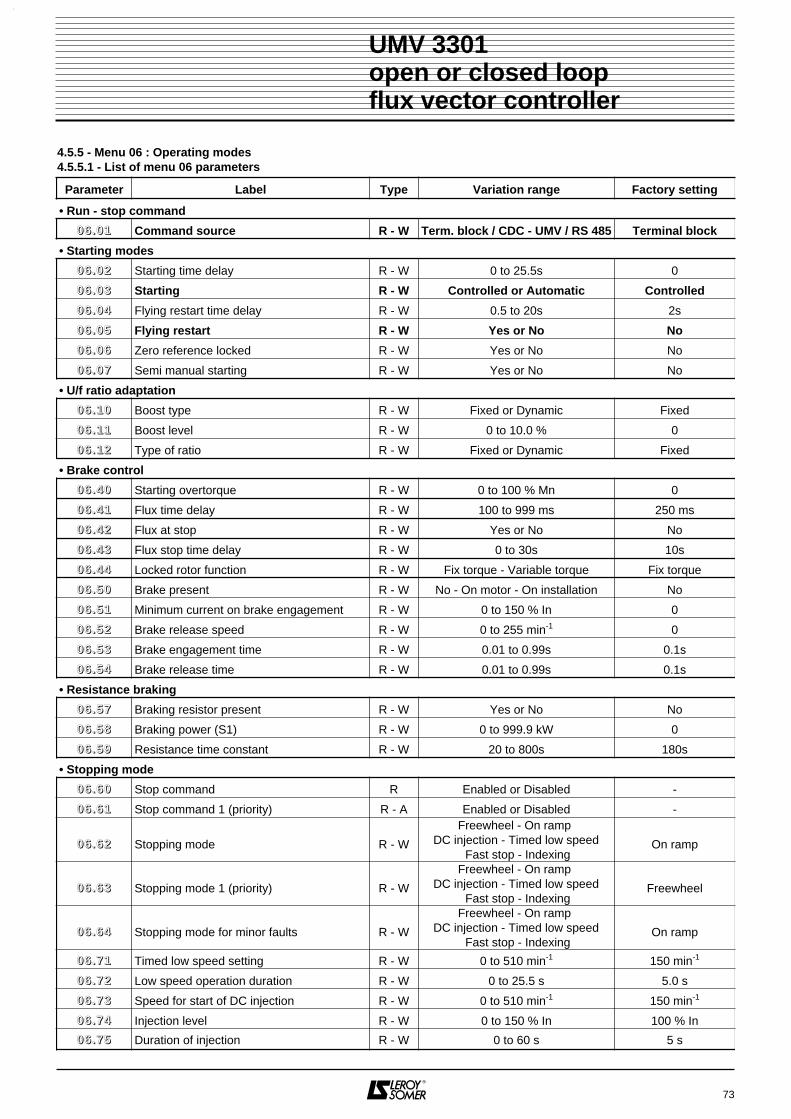
73
UMV 3301open or closed loopflux vector controller
Parameter Label Type Variation range Factory setting
• Run - stop command
00 66 .. 00 11 Command source R - W Term. block / CDC - UMV / RS 485 Terminal block
• Starting modes
00 66 .. 00 22 Starting time delay R - W 0 to 25.5s 0
00 66 .. 00 33 Starting R - W Controlled or Automatic Controlled
00 66 .. 00 44 Flying restart time delay R - W 0.5 to 20s 2s
00 66 .. 00 55 Flying restart R - W Yes or No No
00 66 .. 00 66 Zero reference locked R - W Yes or No No
00 66 .. 00 77 Semi manual starting R - W Yes or No No
• U/f ratio adaptation
00 66 .. 11 00 Boost type R - W Fixed or Dynamic Fixed
00 66 .. 11 11 Boost level R - W 0 to 10.0 % 0
00 66 .. 11 22 Type of ratio R - W Fixed or Dynamic Fixed
• Brake control
00 66 .. 44 00 Starting overtorque R - W 0 to 100 % Mn 0
00 66 .. 44 11 Flux time delay R - W 100 to 999 ms 250 ms
00 66 .. 44 22 Flux at stop R - W Yes or No No
00 66 .. 44 33 Flux stop time delay R - W 0 to 30s 10s
00 66 .. 44 44 Locked rotor function R - W Fix torque - Variable torque Fix torque
00 66 .. 55 00 Brake present R - W No - On motor - On installation No
00 66 .. 55 11 Minimum current on brake engagement R - W 0 to 150 % In 0
00 66 .. 55 22 Brake release speed R - W 0 to 255 min-1 0
00 66 .. 55 33 Brake engagement time R - W 0.01 to 0.99s 0.1s
00 66 .. 55 44 Brake release time R - W 0.01 to 0.99s 0.1s
• Resistance braking
00 66 .. 55 77 Braking resistor present R - W Yes or No No
00 66 .. 55 88 Braking power (S1) R - W 0 to 999.9 kW 0
00 66 .. 55 99 Resistance time constant R - W 20 to 800s 180s
• Stopping mode
00 66 .. 66 00 Stop command R Enabled or Disabled -
00 66 .. 66 11 Stop command 1 (priority) R - A Enabled or Disabled -
00 66 .. 66 22 Stopping mode R - W
Freewheel - On ramp DC injection - Timed low speed
Fast stop - IndexingOn ramp
00 66 .. 66 33 Stopping mode 1 (priority) R - W
Freewheel - On ramp DC injection - Timed low speed
Fast stop - IndexingFreewheel
00 66 .. 66 44 Stopping mode for minor faults R - W
Freewheel - On ramp DC injection - Timed low speed
Fast stop - IndexingOn ramp
00 66 .. 77 11 Timed low speed setting R - W 0 to 510 min-1 150 min-1
00 66 .. 77 22 Low speed operation duration R - W 0 to 25.5 s 5.0 s
00 66 .. 77 33 Speed for start of DC injection R - W 0 to 510 min-1 150 min-1
00 66 .. 77 44 Injection level R - W 0 to 150 % In 100 % In
00 66 .. 77 55 Duration of injection R - W 0 to 60 s 5 s
4.5.5 - Menu 06 : Operating modes4.5.5.1 - List of menu 06 parameters

4.5.5.2 - Menu 06 parameters
: Command sourceRange : Terminal block - CDC-UMV - RS 485Factory setting : Terminal block• Terminal block : the run commands and othercommands come from the terminal block.• CDC - UMV : the run commands and fault reset comefrom the console (RUN + or ).• RS 485 : the controller is piloted via the serial linkconnected at P3 (MODBUS protocol).
: Starting time delayRange : 0 to 20.0sFactory setting : 0sThis function is used to delay the start of rotation of themotor with respect to the run command.
: StartingRange : Controlled or AutomaticFactory setting : ControlledControlled : external command via the terminalblock.Automatic : if a run command is already selected, themotor will start at power up. A stop must first be made,followed by a run command.WARNING :A time delay of longer than 0.5s must be set in00 66 .. 00 22.
: Flying restart time delayRange : 0.5 to 20.0sFactory setting : 2.0sEnables the start of the flying restart function to bedelayed.
: Flying restartRange : Yes or NoFactory setting : NoYes : enables a rotating motor to be powered up, forexample starting a motorised fan which is backdriving in achimney.
No : function inhibited.
: Zero reference lockedRange : Yes or NoFactory setting : NoYes : starting is prohibited if a reference other than zerois present even if a run command is transmitted. Thereference must be reset to 0 before starting.
No : function disabled.
: Semi manual startingRange : Yes or NoFactory setting : NoYes : if 00 66 .. 00 33 is set to " Controlled ", the drive will notstart automatically, if the start command is given beforea power up or before a reset following a trip. In this case,the start command will have to be set to 0 and to 1again.No : drive starting will operate as set in 00 66 .. 00 33.
: BoostRange : Fixed or DynamicFactory setting : FixedFixed : in U/f ratio, on starting, the supply voltage isincreased by a fixed value which is set via 00 66 .. 11 11.Dynamic : in U/f ratio, on starting, the supply voltage isincreased by a value which is in proportion with the loadin order to reach 00 66 .. 11 11 at full load.
: Boost levelRange : 0 to 10.0 %Factory setting : 0For setting the starting voltage applied to the motor inmanual boost.
: Type of ratioRange : Fixed or DynamicFactory setting : FixedFixed : the output voltage/frequency curve is astraight line. This is used for constant torque appli-cations.Dynamic : the output voltage/frequency curve is y = x2
type. This is used for pumps, fans, etc.
74
UMV 3301open or closed loopflux vector controller
N (min )-1
t
t1
0
06.06 = Yes
Speed reference
t1
0
Run instruction
00 66 .. 00 11
N (min )-1
t
t1
0
06.05 = Yes
Run instruction
00 66 .. 00 22
00 66 .. 00 33
00 66 .. 00 44
00 66 .. 00 55
00 66 .. 00 66
00 66 .. 00 77
00 66 .. 11 00
00 66 .. 11 11
00 66 .. 11 22

: Starting overtorqueRange : 0 to 100 % MnFactory setting : 0In closed loop, this parameter allows to increase the va-lue of the magnetising current at very low speed thusproviding more torque.e.g. : if 00 66 .. 44 00 is set at 50 % Mn, the magnetizing currentat very low speed will be 150 %.
: Flux time delayRange : 100 to 999msFactory setting : 250 msDepending on motor characteristics, this parameter isused to decrease the flux start time before motor rota-tion.On hoist, this allows to set the torque quicker before thebrake release.
: Flux at stopRange : Yes or NoFactory setting : NoYes : once the motor is stopped, the drive continues todeliver the magnetizing current during a programmabletime (00 66 .. 44 33). For hoist applications, it saves the fluxstart time before brake release when starting frequently.No : the drive is disabled once the motor is stopped.
: Flux stop time delayRange : 0 to 30sFactory setting : 10sIf flux at standstill is selected, this parameter is used toset the time between the end of the stopping sequenceand the drive disable.
: Locked rotor functionRange : Fix torque or variable torqueFactory setting : Fix torqueFor hoist applications, this parameter is used to selectthe brake release condition.Fix torque : on start command, the torque referenceset in 00 44 .. 11 33 is applied. When the torque level set in00 66 .. 55 11 is reached, the brake is released.Variable torque : on start command, a low speed refe-rence is given. As the brake is closed, the torque will rai-se up to a limit set in 00 44 .. 33 44. When the torque level set in00 66 .. 55 11 is reached, the brake is released.
: Brake presentRange : No - On motor - On installationFactory setting : NoDeclare the presence of a brake and its location.
: Minimum current on brake engagementRange : 0 to 150 % InFactory setting : 0Is used to set the motor current threshold level abovewhich the electromechanical brake (optional) on themotor is released. Backdriving is thus avoided by onlyfreeing the motor shaft when the torque is established.See graph 00 66 .. 55 22.
: Brake release speedRange : 0 to 255 min-1
Factory setting : 0Is used to set the speed threshold level above which theelectromechanical brake (optional) on the motor isengaged. Braking can thus be performed before themotor comes to a complete stop, and can be inhibited untilthe motor speed has reached this threshold.
: Brake : engagement timeRange : 0.01 to 99.9sFactory setting : 0.1sEnter here the characteristic of the brake used.
: Brake : release timeRange : 0.01 to 99.9sFactory setting : 0.1sEnter here the characteristic of the brake used.
: Braking resistor presentRange : Yes or NoFactory setting : NoYes : the optional braking transistor is controlled whenthe DC bus voltage exceeds 725V. A braking resistormust be wired between terminals RF1 and RF2 across athermal relay.The DC bus voltage is automatically limited to the valueof 00 44 .. 77 11.Note : The braking capacity of the controller is very poor.No : no braking resistor present.
75
UMV 3301open or closed loopflux vector controller
00 66 .. 44 00 00 66 .. 55 11
00 66 .. 44 11
00 66 .. 44 22
00 66 .. 44 33
00 66 .. 44 44
00 66 .. 55 00
00 66 .. 55 22
InN
N
t
t
06.51
10.51 = 0
06.52
Brake released1
0
brake
In
00 66 .. 55 33
00 66 .. 55 44
00 66 .. 55 77

: Braking power (S1)Range : 0 to 999.9 kWFactory setting : 0Enter here the thermal power of the braking resistor.
: Thermal time constantRange : 20 to 800sFactory setting : 180sEnter the time constant according to the resistor used.
: Stop command
Range : Enabled or DisabledDisplays the stop command coming from the FWD andREV inputs.
: Stop command 1Range : Enabled or DisabledDisplays stop command 1 coming from a programmablelogic input. This stop command takes priority.
and : Stopping mode - Stopping mode 1
Range : Freewheel - On ramp - DC injection - Timed low speed - Fast stop - Indexing
Factory setting : 00 66 .. 66 22 = On ramp00 66 .. 66 33 = Freewheel
At a stop command (00 66 .. 66 00 or 00 66 .. 66 11 enabled) 00 66 .. 66 22and 00 66 .. 66 33 are used to select the stopping conditionsaccording to the application.Note : stopping mode 1 takes priority over all otherstopping modes.Freewheel stop : the motor is no longer supplied andstops on its own inertia.On ramp : the motor decelerates following the rampdefined in menu 3.DC injection : the motor decelerates following the rampup to 00 66 .. 77 33 then DC current is injected (level 00 66 .. 77 44) inthe motor during 00 66 .. 77 55 in order to brake the motor.Timed low speed : the motor decelerates following theramp up to the step defined by 00 66 .. 77 11 during 00 66 .. 77 22 thenthe motor decelerates in freewheel on its own inertia.Fast stop : the motor decelerates as fast as possible upto the DC bus overvoltage limit and the generator torquelimit 00 44 .. 33 77.Indexing : the motor decelerates following the ramp upto the step defined by 00 66 .. 77 11 for a period at least equalto 00 66 .. 77 22, then when input IP5 is activated, DC current isinjected (according to 00 66 .. 77 44 and 00 66 .. 77 55) in the motor.Logic input DI5 must not be assigned to any other use(00 88 .. 55 11 = none).See timing diagrams.
: Minor faults modeRange : Freewheel - On ramp - DC injection -
Timed low speed - Fast stop - IndexingFactory setting : On rampWhen a minor fault is detected (11 00 .. 00 44 = minor fault),00 66 .. 66 44 is used to select the stop conditions. See 00 66 .. 66 22and 00 66 .. 66 33.
: Timed low speed settingRange : 0 to 510 min-1
Factory setting : 150 min-1
Speed to be reached following the ramp when stop withlow speed is selected in 00 66 .. 66 22, 00 66 .. 66 33 or 00 66 .. 66 44, thenstop following the ramp after the period set in 00 66 .. 77 22.
: Low speed operation durationRange : 0 to 25.5sFactory setting : 5sDuration of operation at low speed (00 66 .. 77 11) beforefreewheel stop.
76
UMV 3301open or closed loopflux vector controller
R - UMV resistor Constant (s)27500 5955000 5975000 6090000110000 Consult LEROY-SOMER132000
00 66 .. 55 88
00 66 .. 55 99
00 66 .. 66 00
00 66 .. 66 11
00 66 .. 66 22 00 66 .. 66 33
N (min )
06.73
-1
t
t
1
0
Stop or stop 1 control
FreewheelOn rampDC injection
N (min )
06.71
06.71
-1
t
Fast stopTimed LSPIndexing
DCinjection
DI5
00 66 .. 66 44
00 66 .. 77 11
00 66 .. 77 22
N
t
06.71
06.72Stopinstruction
Freewheel
Decelerationramp

: Speed for start of DC injectionRange : 0 to 510 min-1
Factory setting : 150 min-1
Speed from which DC current is injected in the motor.
: DC injection levelRange : 0 to 150 % InFactory setting : 100 % InSets the level of DC current injected in the motor in orderto stop it.
: Duration of DC injectionRange : 0 to 60sFactory setting : 5sPeriod during which the current defined in 00 66 .. 77 44 isapplied to the motor.
77
UMV 3301open or closed loopflux vector controller
00 66 .. 77 33
00 66 .. 77 44
00 66 .. 77 55
N
t
06.73
06.75Stopinstruction
Decelerationramp
Holding
Deceleration linked to currentinjection 06.74

4.5.5.3 - Menu 06 block diagram
78
UMV 3301open or closed loopflux vector controller
06.75 Duration of injection
Level of injection
Speed at start ofDC injection
Freewheel stop
Stop on ramp
Stop withDC injection
Stop withtimed LSP
Fast stop
Stop indexedwith switch 5
Shortest possibleramp
06.74
06.73
Stop 06.62
Low speed (LSP)
LSP time delay
06.71
06.72
STOPPING MODES
• Starting overtorque
• Flux time delay
• Flux at stop
• Flux stop time delay
• Locked rotor function
• Brake present
• Current on engagement
• Speed on release
• Engagement time
• Release time
06.40
06.41
BRAKE CONTROL
0
1
5
4
3
2
Main stop
06.42
06.43
06.50
06.44
• Braking resistors present
• Braking power
• Thermal time constant
06.57
06.58
RESISTANCE BRAKING
06.59
Stop1 (priority)
Minor faults
• Time delay on starting
• Starting
• Time delay on flying restart
• Flying restart
• Zero reference locked
• Semi manual starting
automatic
controlled
enabled
disabled
1
0
1
0
06.04
06.06
06.07
STARTING MODES
Dynamic
Fixed
1
0
• Boost
• Boost level
• Type
06.11
U/F RATIO ADAPTATION
06.10
Dynamic
Fixed1
0
06.12
Terminal block
CDC UMV
RS 485 serial link
• Command source
RUN/STOP COMMAND
06.01
06.05
06.03
External fault
LockENABLE
EXT-FLT
Major faults
Cause of stopping
Selection
Stopping mode
Stop 1 06.63
Minor faults 06.64
06.60
06.61
06.02
06.51
06.52
06.53
06.54

79
UMV 3301open or closed loopflux vector controller
4.5.6 - Menu 07 : Analogue I/O4.5.6.1 - List of menu 07 parameters
Parameter Label Type Variation range Factory setting
• Analogue inputs
00 77 .. 11 00 AI1 reading R ± 100.00 % -
00 77 .. 11 11 AI1 offset R - W ± 100.00 % 0
00 77 .. 11 22 AI1 offset selection R - W Yes or No No
00 77 .. 11 33 AI1 minimum calibration R - W 0 to 100.00 % 0
00 77 .. 11 44 AI1 maximum calibration R - W 0 to 100.00 % 100.00 %
00 77 .. 11 55 AI1 input polarity R - W Single pole - 2-pole 2-pole
00 77 .. 11 77 AI1 100 % calibration R - W 0 to 32000 1500
00 77 .. 11 88 AI1 final value R ± 8192 -
00 77 .. 11 99 AI1 destination R - W See table on next page Speed no.1
00 77 .. 22 00 AI2 reading R ± 100 % -
00 77 .. 22 11 AI2 offset R - W ± 100.0 % 0
00 77 .. 22 22 AI2 offset selection R - W Yes or No No
00 77 .. 22 33 AI2 minimum calibration R - W 0 to 100.0 % 0
00 77 .. 22 44 AI2 maximum calibration R - W 0 to 100.0 % 100.0 %
00 77 .. 22 55 AI2 input polarity R - W Single pole - 2-pole 2-pole
00 77 .. 22 77 AI2 100 % calibration R - W 0 to 32000 100
00 77 .. 22 88 AI2 final value R ± 8192 -
00 77 .. 22 99 AI2 destination R - W See table on next page None
00 77 .. 33 00 AI3 reading R 0 to +100.0 % -
00 77 .. 33 33 AI3 0 % calibration R - W 0 to 32000 0
00 77 .. 33 44 AI3 100 % calibration R - W 0 to 32000 1500
00 77 .. 33 55 AI3 input inversion R - W Yes or No No
00 77 .. 33 66 AI3 reference selection R - W 0/10V - 0/20mA - 4/20mA 4/20 mA
00 77 .. 33 77 AI3 scaling R 0 to 999.9 -
00 77 .. 33 88 AI3 final value R ± 8192 -
00 77 .. 33 99 AI3 destination R - W See table on next page Speed no. 2
00 77 .. 44 00 AI4 reading (THERM) R 0 to 100.0 % -
00 77 .. 44 11 Thermistor state R 0 or 1 -
• Analogue outputs
00 77 .. 55 00 AO1 reading R ± 100.0 % -
00 77 .. 55 11 AO1 signal conversion R - W Yes or No No
00 77 .. 55 22 AO1 type selection R - W 0 - 10V, 0 - 20mA, 4 - 20mA 4 - 20 mA
00 77 .. 55 33 AO1 output filter R - W 0 to 15 2
00 77 .. 55 77 AO1 100 % calibration R - W 0 to 32000 150
00 77 .. 55 99 AO1 signal source R - W See table on next page Total motor current
00 77 .. 66 00 AO2 reading R ± 100.0 % -
00 77 .. 66 11 AO2 signal conversion R - W Yes or No No
00 77 .. 66 22 AO2 type selection R - W 0 - 10V, 0 - 20mA, 4 - 20mA 4 - 20 mA
00 77 .. 66 33 AO2 output filter R - W 0 to 15 2
00 77 .. 66 77 AO2 100 % calibration R - W 0 to 32000 1800
00 77 .. 66 99 AO2 signal source R - W See table on next page Motor speed
00 77 .. 77 00 Mains voltage R 0 to 999V -
00 77 .. 88 00 DC bus voltage R 0 to 1300V -

80
UMV 3301open or closed loopflux vector controller
Analog input destinations list (00 77 .. 11 99, 00 77 .. 22 99, 00 77 .. 33 99)
Parameter Label Parameter Label
- None 00 77 .. 11 00 AI1 reading (%)
00 22 .. 00 11 Speed reference before ramp 00 77 .. 11 88 AI1 final value
00 22 .. 88 00 Reference before limiting 00 77 .. 22 00 AI2 reading (%)
00 33 .. 00 11 Final speed reference 00 77 .. 22 88 AI2 final value
00 44 .. 00 11 Motor speed 00 77 .. 33 00 AI3 reading (%)
00 44 .. 00 22 Speed error 00 77 .. 33 88 AI3 final value
00 44 .. 00 66 Speed reached error 00 77 .. 44 00 AI4 reading (%)
00 44 .. 22 00 Final torque reference 00 77 .. 77 00 Mains voltage
00 44 .. 44 00 Active current reference 00 77 .. 88 00 DC bus voltage
00 44 .. 44 22 Total motor current 11 00 .. 77 00 Motor use
00 44 .. 44 44 Active motor current 11 00 .. 77 55 Controller use
00 44 .. 55 00 Motor torque 11 00 .. 88 00 Braking resistor use
00 44 .. 66 00 Motor frequency 11 44 .. 00 11 PID output reading
00 44 .. 77 00 Motor voltage 11 44 .. 22 00 PID final reference
00 44 .. 88 00 Motor active power 11 44 .. 33 00 PID feedback
00 44 .. 88 11 Energy 1 (MW.h) 11 44 .. 44 00 PID error
00 44 .. 88 22 Energy 2 (KW.h) 11 55 .. 11 00 Customer torque
00 44 .. 99 00 Encoder frequency 11 66 .. 00 66 Voltage error
00 44 .. 99 22 Remanent frequency
Parameter Label Parameter Label
- None 00 55 .. 00 22 Current limit time threshold
00 22 .. 11 11 Speed reference 1 00 55 .. 11 22 Alarm 1 threshold
00 22 .. 11 22 Speed reference 2 00 55 .. 22 22 Alarm 2 threshold
00 22 .. 11 33 Additional speed reference 00 55 .. 33 22 Alarm 3 threshold
00 22 .. 44 00 Jogging reference 00 55 .. 44 22 Alarm 4 threshold
00 22 .. 88 33 Speed limiting 00 77 .. 11 77 AI1 scaling
00 33 .. 00 33 Additional reference without ramp 00 77 .. 22 77 AI2 scaling
00 33 .. 11 00 Main ramp 1 11 00 .. 00 66 Mains undervoltage threshold
00 33 .. 33 00 Main ramp n°3 11 22 .. 11 22 Variable threshold 1
00 44 .. 11 00 Torque reference 11 22 .. 22 22 Variable threshold 2
00 44 .. 11 33 Torque offset 11 44 .. 11 00 PID reference
00 44 .. 33 44 Torque limit 1 in motor mode 11 44 .. 33 00 PID feedback
00 44 .. 33 66 Torque 2 limiting 11 44 .. 44 55 PID limit
00 44 .. 33 77 Torque limit 1 in generator mode 11 44 .. 44 99 PID additionnal reference
00 44 .. 66 99 Motor speed adaptation threshold 11 66 .. 00 22 DC bus reference
Analog output sources list (00 77 .. 55 99 and 00 77 .. 66 99)

4.5.6.2 - Menu 07 parameters
and : AI1 - AI2 reading
Range : 00 77 .. 11 00 : ± 100.00 %00 77 .. 22 00 : ± 100.0 %
Used to read the corresponding analogue input.
and : AI1 - AI2 offsetRange : 00 77 .. 11 11 : ± 100.00 %
00 77 .. 22 11 : ± 100.0 %Factory setting : 0Modifies the reference value when the offset is selected(00 77 .. 11 22 or 00 77 .. 22 22 = Yes).
and : AI1 - AI2 offset selectionRange : Yes or NoFactory setting : NoYes : the offset (00 77 .. 11 11 or 00 77 .. 22 11) is added to the valueof the analogue input (00 77 .. 11 00 or 00 77 .. 22 00).No : the reference is not modified before calibration.
and : AI1 - AI2 minimumcalibration
Range : 00 77 .. 11 33 : 0 to 100.00 %00 77 .. 22 33 : 0 to 100.0 %
Factory setting : 0Limits the minimum value of the analogue input (AI1 orAI2) associated with its offset.Minimum calibration is inhibited when 00 77 .. 11 55 or 00 77 .. 22 55 =2-pole.
and : AI1 - AI2 maximumcalibration
Range : 00 77 .. 11 44 : 0 to 100.00 %00 77 .. 22 44 : 0 to 100.0 %
Factory setting : 00 77 .. 11 44 : 100.00 %00 77 .. 22 44 : 100.0 %
Limits the maximum value of analogue input AI1 or AI2associated with its offset.
and : AI1 - AI2 input polarityRange : Single pole - 2-poleFactory setting : 2-poleSingle pole : only a positive reference is taken into account.A negative reference is treated as a zero reference.2-pole : the reference can be positive or negative. Inthis case, a minimum calibration cannot be appliedto the reference.
• If inputs AI1 and AI2 are selected in 2-pole mode, the minimum speeds 00 22 .. 88 11 and 00 22 .. 88 22
must be left at 0.
and : AI1 and AI2 100 %calibration
Range : 0 to 32000Factory setting : 00 77 .. 11 77 : 1500
00 77 .. 22 77 : 100For setting the value corresponding to 100 % on theanalogue input.
and : AI1 - AI2 final value
Range : ± 8192This is the reading of the value of the AI1 or AI2 signalafter processing (offset, calibration, scaling) which will beassigned via 00 77 .. 11 99 or 00 77 .. 22 99.
and : AI1 - AI2 destinationRange : See table in section 4.5.6.1Factory setting : 00 77 .. 11 99 = speed reference 1
00 77 .. 22 99 = noneSelects the destination of analogue input AI1 or AI2.
: AI3 reading
Range : 0 to 100.0 %Is used to read input AI3.
: AI3 0 % calibrationRange : 0 to 32000Factory setting : 0Is used to give 0 % any value from 0 to 8000. The valueset depends on the assignment of 00 77 .. 33 99.
: AI3 100 % calibrationRange : 0 to 32000Factory setting : 1500Is used to give 100 % any value from 0 to 8000. Thevalue set depends on the assignment of 00 77 .. 33 99.
: AI3 input inversionRange : Yes or NoFactory setting : NoYes : multiplies the value of input AI3 by -1.No : the polarity of the reference is unchanged.
: AI3 reference selectionRange : 0-10V, 0-20mA, 4-20mAFactory setting : 4-20mASelection according to the type of signal at input AI3.
: AI3 scaling
Range : 0 to 999.9Scaling coefficient on input AI3 as a function of thecalibration of 00 77 .. 33 33 and 00 77 .. 33 44.
: AI3 final value
Range : ± 8192This is the reading of the value of the AI3 signal afterprocessing (calibration, inversion).
81
UMV 3301open or closed loopflux vector controller
00 77 .. 11 00
00 77 .. 11 11
00 77 .. 22 00
00 77 .. 22 11
00 77 .. 11 22 00 77 .. 22 22
00 77 .. 11 33 00 77 .. 22 33
00 77 .. 11 44 00 77 .. 22 44
00 77 .. 11 55 00 77 .. 22 55
00 77 .. 11 77 00 77 .. 22 77
00 77 .. 11 88
00 77 .. 11 99
00 77 .. 22 88
00 77 .. 22 99
00 77 .. 33 00
00 77 .. 33 33
N
07.331500
07.34
07.34
07.338000
00 10V
Reference
Factory
setting
00 77 .. 33 44
00 77 .. 33 55
00 77 .. 33 66
00 77 .. 33 77
00 77 .. 33 88

: AI3 destinationRange : See assignment table in section 4.5.6.1Factory setting : Speed reference no. 2.Selects the destination of input AI3.
: AI4 reading (THERM)
Range : 0 to 100.0 %.Is used to read input AI4 (motr probe).See 00 11 .. 33 00 and 11 00 .. 11 00.
: Thermistor state
Range : 0 or 10 : the motor temperature is correct.1 : the motor temperature is too high, the controller becomes faulty depending on the setting of 11 00 .. 11 00.Note : Up to 3 PTC probes can be managed.
and : AO1 - AO2 reading
Range : ± 100.0 %Is used to read analogue output AO1 or AO2.
and : AO1 and AO2 signal conversion
Range : Yes or NoFactory setting : NoYes : the 0 - 20 mA and 4 - 20 mA signals are inverted.0 % as an input gives 20mA as an output, and 100 % asan input gives 0 or 4 mA as an output.No : the 0 - 20 mA and 4 - 20 mA signals are not invert-ed.
and : AO1 - AO2 type selectionRange : 0 - 10V, 0- 20mA, 4 - 20mAFactory setting : 4 - 20mASelection of the signal supplied by the analogue output.Note : The 4-20mA and 0-20mA signals can be invertedvia 00 77 .. 55 11 and 00 77 .. 66 11.
and : AO1 - AO2 output filterRange : 0 to 15Factory setting : 2Applies a filter to the analog outputs in order to reducethe noise.
and : AO1 - AO2 100 %calibration
Range : 0 to 32000Factory setting : AO1 : 150, AO2 : 1800Scaling of the signal selected via the source 00 77 .. 55 99 or00 77 .. 66 99.
and : AO1 - AO2 sourceRange : see assignment table in section 4.5.6.1Factory setting : 00 77 .. 55 99 = motor current
00 77 .. 66 99 = motor speedSelects the source of the signal destined for analoguesignal AO1 or AO2.
: Mains voltage
Range : 0 to 999VMeasurement of the voltage at the controller input.
: DC bus voltage
Range : 0 to 1300VMeasurement of the voltage on the DC bus between therectifier and the inverter.
82
UMV 3301open or closed loopflux vector controller
00 77 .. 33 99
00 77 .. 55 00 00 77 .. 66 00
00 77 .. 44 00
00 77 .. 44 11
00 77 .. 55 11 00 77 .. 66 11
00 77 .. 55 22 00 77 .. 66 22
00 77 .. 55 33 00 77 .. 66 33
00 77 .. 55 77 00 77 .. 66 77
00 77 .. 55 99 00 77 .. 66 99
00 77 .. 77 00
00 77 .. 88 00

83
UMV 3301open or closed loopflux vector controller
NOTES

84
UMV 3301open or closed loopflux vector controller
4.5.6.3 - Menu 07 block diagram (1)
Diff±10V
++
AI1destination
10
AI1+
Readinput
AI1-
OffsetOffset
selection
100 %calibration
AI2 finalvalue
AI1 finalvalue
07.10
07.11
07.1207.18
07.17
07.19
AI1 inputpolarity
07.15
2-pole
07.14
07.14
07.14
07.13
1-pole
±10V+
+
AI2destination
10
AI2
Readinput
OffsetOffset
selection
100 %calibration
07.20
07.21
07.2207.28
07.27
07.29
AI2 inputpolarity
07.25
2-pole
07.24
07.24
07.24
07.23
1-pole
Thermistorprotectiondisabled
Thermistorinput
Motor thermistorfault
1
0
AI4
0V
07.40
01.30
10.10
Motor PTC faultprocessing
AI30/20mA
4/20mA
0/10V
Signal typeselection
ReadAI3 (%)
07.30
07.37
07.41
07.36 AI3 inputdestination
AI3 input inversion
AI3 finalvalue
1
0
AI3scaling
PTC status
X (-1) 07.38
07.35
07.39
Conversion0/20mA --> 0/100%4/20mA --> 0/100%
Calibration
07.33
07.34
of 0 %
of 100 %
1800Ω
3300Ω
Mot Th fault
R
t
ReadAI4 (%)
X(-1)
= 1
Read/write
Read-only
Read and assign
Logic inversion
Exclusive OR function
& Logic AND function

85
UMV 3301open or closed loopflux vector controller
4.5.6.3 - Menu 07 block diagram (2)
AO1 source
10Vcalibration
AO1
AO1 typeselection
07.59
AO1 signalconversion
07.51
AO2 signalconversion
07.61
Read AO1
07.50
07.70
07.80
Mains voltage
DC Bus voltage
07.52
07.57
AO2 source
07.69
X(-1)
= 1
Read/write
Read-only
Read and assign
Logic inversion
Exclusive OR function
& Logic AND function
100
100
100
1000 --> 4 mA
100 --> 20 mA
0 --> 0 mA100 --> 20 mA
+100 --> +10V-100 --> -10V
10Vcalibration
AO2
AO2 typeselection
Read AO2
07.60
07.62
07.67
100
100
100
1000 --> 4 mA
100 --> 20 mA
0 --> 0 mA100 --> 20 mA
+100 --> +10V-100 --> -10V
AO1 outputfilter
AO2 outputfilter
07.53
07.63

86
UMV 3301open or closed loopflux vector controller
NOTES
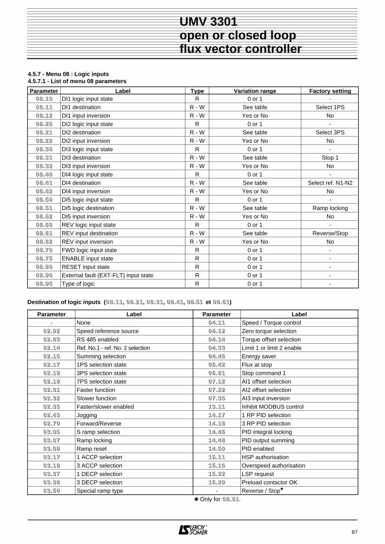
87
UMV 3301open or closed loopflux vector controller
4.5.7 - Menu 08 : Logic inputs4.5.7.1 - List of menu 08 parameters
Parameter Label Type Variation range Factory setting00 88 .. 11 00 DI1 logic input state R 0 or 1 -00 88 .. 11 11 DI1 destination R - W See table Select 1PS00 88 .. 11 22 DI1 input inversion R - W Yes or No No00 88 .. 22 00 DI2 logic input state R 0 or 1 -00 88 .. 22 11 DI2 destination R - W See table Select 3PS00 88 .. 22 22 DI2 input inversion R - W Yes or No No00 88 .. 33 00 DI3 logic input state R 0 or 1 -00 88 .. 33 11 DI3 destination R - W See table Stop 100 88 .. 33 22 DI3 input inversion R - W Yes or No No00 88 .. 44 00 DI4 logic input state R 0 or 1 -00 88 .. 44 11 DI4 destination R - W See table Select ref. N1-N200 88 .. 44 22 DI4 input inversion R - W Yes or No No00 88 .. 55 00 DI5 logic input state R 0 or 1 -00 88 .. 55 11 DI5 logic destination R - W See table Ramp locking00 88 .. 55 22 DI5 input inversion R - W Yes or No No00 88 .. 66 00 REV logic input state R 0 or 1 -00 88 .. 66 11 REV input destination R - W See table Reverse/Stop00 88 .. 66 22 REV input inversion R - W Yes or No No00 88 .. 77 00 FWD logic input state R 0 or 1 -00 88 .. 77 55 ENABLE input state R 0 or 1 -00 88 .. 88 00 RESET input state R 0 or 1 -00 88 .. 99 00 External fault (EXT-FLT) input state R 0 or 1 -00 88 .. 99 55 Type of logic R 0 or 1 -
Destination of logic inputs (00 88 .. 11 11, 00 88 .. 22 11, 00 88 .. 33 11, 00 88 .. 44 11, 0088..5511 et 00 88 .. 66 11)
Parameter Label Parameter Label- None 00 44 .. 11 11 Speed / Torque control
00 22 .. 00 22 Speed reference source 00 44 .. 11 22 Zero torque selection00 22 .. 00 33 RS 485 enabled 00 44 .. 11 44 Torque offset selection00 22 .. 11 44 Ref. No.1 - ref. No. 2 selection 00 44 .. 33 33 Limit 1 or limit 2 enable00 22 .. 11 55 Summing selection 00 44 .. 44 66 Energy saver00 22 .. 11 77 1PS selection state 00 66 .. 44 22 Flux at stop00 22 .. 11 88 3PS selection state 00 66 .. 66 11 Stop command 100 22 .. 11 99 7PS selection state 00 77 .. 11 22 AI1 offset selection00 22 .. 33 11 Faster function 00 77 .. 22 22 AI2 offset selection00 22 .. 33 22 Slower function 00 77 .. 33 55 AI3 input inversion00 22 .. 33 33 Faster/slower enabled 11 33 .. 11 11 Inhibit MODBUS control00 22 .. 44 33 Jogging 11 44 .. 11 77 1 RP PID selection00 22 .. 77 00 Forward/Reverse 11 44 .. 11 88 3 RP PID selection00 33 .. 00 55 S ramp selection 11 44 .. 44 66 PID integral locking00 33 .. 00 77 Ramp locking 11 44 .. 44 88 PID output summing00 33 .. 00 88 Ramp reset 11 44 .. 55 00 PID enabled00 33 .. 11 77 1 ACCP selection 11 55 .. 11 11 HSP authorisation00 33 .. 11 88 3 ACCP selection 11 55 .. 11 66 Overspeed authorisation00 33 .. 33 77 1 DECP selection 11 55 .. 22 22 LSP request00 33 .. 33 88 3 DECP selection 11 66 .. 22 00 Preload contactor OK00 33 .. 55 00 Special ramp type - Reverse / Stop
Only for 00 88 .. 66 11.
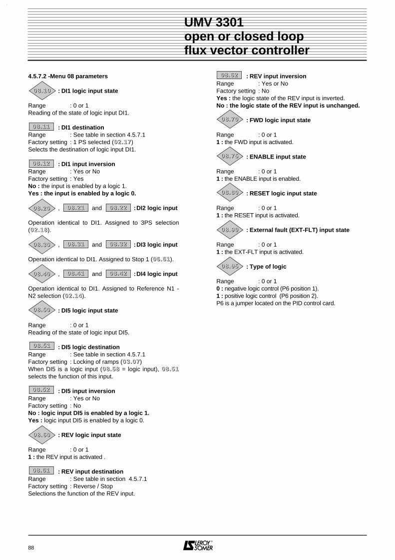
4.5.7.2 -Menu 08 parameters
: DI1 logic input state
Range : 0 or 1Reading of the state of logic input DI1.
: DI1 destinationRange : See table in section 4.5.7.1Factory setting : 1 PS selected (00 22 .. 11 77)Selects the destination of logic input DI1.
: DI1 input inversionRange : Yes or NoFactory setting : YesNo : the input is enabled by a logic 1.Yes : the input is enabled by a logic 0.
, and :DI2 logic input
Operation identical to DI1. Assigned to 3PS selection(00 22 .. 11 88).
, and :DI3 logic input Operation identical to DI1. Assigned to Stop 1 (00 66 .. 66 11).
, and :DI4 logic input Operation identical to DI1. Assigned to Reference N1 -N2 selection (00 22 .. 11 44).
: DI5 logic input state
Range : 0 or 1Reading of the state of logic input DI5.
: DI5 logic destinationRange : See table in section 4.5.7.1Factory setting : Locking of ramps (00 33 .. 00 77)When DI5 is a logic input (00 88 .. 55 88 = logic input), 00 88 .. 55 11selects the function of this input.
: DI5 input inversionRange : Yes or NoFactory setting : NoNo : logic input DI5 is enabled by a logic 1.Yes : logic input DI5 is enabled by a logic 0.
: REV logic input state
Range : 0 or 11 : the REV input is activated .
: REV input destinationRange : See table in section 4.5.7.1Factory setting : Reverse / StopSelections the function of the REV input.
: REV input inversionRange : Yes or NoFactory setting : NoYes : the logic state of the REV input is inverted.No : the logic state of the REV input is unchanged.
: FWD logic input state
Range : 0 or 11 : the FWD input is activated.
: ENABLE input state
Range : 0 or 11 : the ENABLE input is enabled.
: RESET logic input state
Range : 0 or 11 : the RESET input is activated.
: External fault (EXT-FLT) input state
Range : 0 or 11 : the EXT-FLT input is activated.
: Type of logic
Range : 0 or 10 : negative logic control (P6 position 1).1 : positive logic control (P6 position 2).P6 is a jumper located on the PID control card.
88
UMV 3301open or closed loopflux vector controller
00 88 .. 11 11
00 88 .. 11 00
00 88 .. 11 22
00 88 .. 22 00 00 88 .. 22 11 00 88 .. 22 22
00 88 .. 33 00 00 88 .. 33 11 00 88 .. 33 22
00 88 .. 44 00 00 88 .. 44 11 00 88 .. 44 22
00 88 .. 55 00
00 88 .. 55 11
00 88 .. 55 22
00 88 .. 66 11
00 88 .. 66 00
00 88 .. 66 22
00 88 .. 77 00
00 88 .. 77 55
00 88 .. 88 00
00 88 .. 99 00
00 88 .. 99 55

89
UMV 3301open or closed loopflux vector controller
NOTES

90
UMV 3301open or closed loopflux vector controller
4.5.7.3 - Menu 08 block diagram (1)
DI1 destination
DI1 inputstate
DI1logic
inversion
0
1
08.12
X (-1)
08.11
08.10DI1
DI2 destinationt
DI2 inputstate
DI2logic
inversion
0
1
08.22
X (-1)
08.21
08.20DI2
DI3 destination
DI3 inputstate
DI3logic
inversion
0
1
08.32
X (-1)
08.31
08.30DI3
DI4 destination
DI4 inputstate
DI4logic
inversion
0
1
08.42
X (-1)
08.41
08.40DI4
X(-1)
= 1
Read/write
Read-only
Read and assign
Logic inversion
Exclusive OR function
& Logic AND function
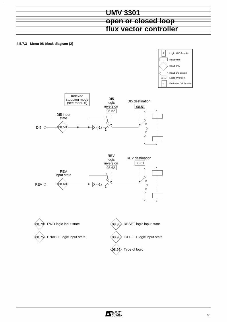
91
UMV 3301open or closed loopflux vector controller
4.5.7.3 - Menu 08 block diagram (2)
08.70
08.75
FWD logic input state
ENABLE logic input state
08.80
08.90
RESET logic input state
EXT-FLT logic input state
08.95 Type of logic
X(-1)
= 1
Read/write
Read-only
Read and assign
Logic inversion
Exclusive OR function
& Logic AND function
REV destination
REVinput state
REVlogic
inversion
0
1
08.62
X (-1)
08.61
08.60REV
DI5 destination
DI5 inputstate
Indexedstopping mode(see menu 6)
DI5logic
inversion
0
1
08.52
X (-1)
08.51
08.50DI5

92
UMV 3301open or closed loopflux vector controller
NOTES

93
UMV 3301open or closed loopflux vector controller
4.5.8 - Menu 09 : Relays and programmable logic outputs4.5.8.1 - List of menu 09 parameters
Parameter Label Type Variation range Factory setting
• Relay
00 99 .. 11 00 RL1 relay status R Open or Closed -
00 99 .. 11 11 RL1 source 1 R - W See table Alarm 1 state
00 99 .. 11 22 RL1 source 1 inverted R - W Yes or No No
00 99 .. 11 33 RL1 source 2 R - W See table No assignment
00 99 .. 11 44 RL1 source 2 inverted R - W Yes or No No
00 99 .. 11 55 RL1 relay inverted R - W Yes or No Yes
00 99 .. 11 66 RL1 relay time delay R - W 0 to 25.5s 2 s
00 99 .. 11 77 RL1 relay selection R - W Single source or Combination Single source
00 99 .. 22 00 RL2 relay status R Open or Closed -
00 99 .. 22 11 RL2 source 1 R - W See table UMV 3301 output
00 99 .. 22 22 RL2 source 1 inverted R - W Yes or No No
00 99 .. 22 33 RL2 source 2 R - W See table No assignment
00 99 .. 22 44 RL2 source 2 inverted R - W Yes or No No
00 99 .. 22 55 RL2 relay inverted R - W Yes or No No
00 99 .. 22 66 RL2 relay time delay R - W 0 to 25.5s 2.0 s
00 99 .. 22 77 RL2 relay selection R - W Single source or Combination Single source
• Logic outputs
00 99 .. 33 00 DO1 logic output state R 0 or 1 -
00 99 .. 33 11 DO1 source R - W See table I limit reached
00 99 .. 33 22 DO1 source inverted R - W Yes or No No
00 99 .. 33 66 DO1 output time delay R - W 0 to 25.5s 2.0 s
00 99 .. 44 00 DO2 logic output state R 0 or 1 -
00 99 .. 44 11 DO2 source R - W See table UMV fault
00 99 .. 44 22 DO2 source inverted R - W Yes or No Yes
00 99 .. 44 66 DO2 output time delay R - W 0 to 25.5s 2.0 s
00 99 .. 55 00 DO3 logic output state R 0 or 1 -
00 99 .. 55 11 DO3 logic information source R - W See table Alarm 2 state
00 99 .. 55 22 DO3 source inversion R - W Yes or No No
00 99 .. 55 66 DO3 output time delay R - W 0 to 25.5s 2.0 s

94
UMV 3301open or closed loopflux vector controller
Sources and assignment of relays and logic outputs (00 99 .. 11 11, 00 99 .. 11 33, 00 99 .. 22 11, 00 99 .. 22 33, 00 99 .. 33 11, 00 99 .. 44 11,00 99 .. 55 11)
Parameter Label Parameter Label
- No assignment 11 00 .. 44 33 Alarm 3 active
00 22 .. 99 00 Speed skip present 11 00 .. 44 44 Alarm 4 active
00 55 .. 55 44 Alarm 5 active 11 00 .. 44 55 Clockwise direction
00 55 .. 55 77 Alarm 6 active 11 00 .. 44 66 Anti-clockwise direction
00 77 .. 44 11 Thermistor state 11 00 .. 44 77 I limit reached
00 88 .. 99 00 External fault 11 00 .. 44 88 DC bus limit reached
11 00 .. 33 22 UMV fault 11 00 .. 44 99 In-rush contactor control
11 00 .. 33 33 UMV output 11 00 .. 55 11 Brake control
11 00 .. 33 44 Minor fault 11 00 .. 66 11 Timed low speed
11 00 .. 33 55 Major fault 11 00 .. 66 22 End of indexing
11 00 .. 33 88 Motor operation 11 00 .. 66 33 Zero speed
11 00 .. 33 99 Generator operation 11 22 .. 00 11 Exceeds threshold 1
11 00 .. 44 00 Time in I limit 11 22 .. 00 22 Exceeds threshold 2
11 00 .. 44 11 Alarm 1 active 11 44 .. 55 33 PID status
11 00 .. 44 22 Alarm 2 active 11 55 .. 11 22 Weighing alarm
11 66 .. 11 22 Network synchronisation OK
Parameter Label Parameter Label
- Bus overvoltage - Mains over V
- Overcurrent - Bus under V
- I Imbalance - Motor TH
- Controller Th. - Motor PTC probe
- Resistor Th. - Direction/Rot
- Int. power supp - Motor phase
- Processor - RS 485 link
- Encoder - CDC - UMV
- Encoder loss - 4/20mA loss
- Processor opt 1 - Alarm 1 active
- Processor opt 2 - Alarm 2 active
- External - Alarm 3 active
- Mains failure - Alarm 4 active
- Phase missing - IGBT
- Mains under V - I limit time
- Overspeed
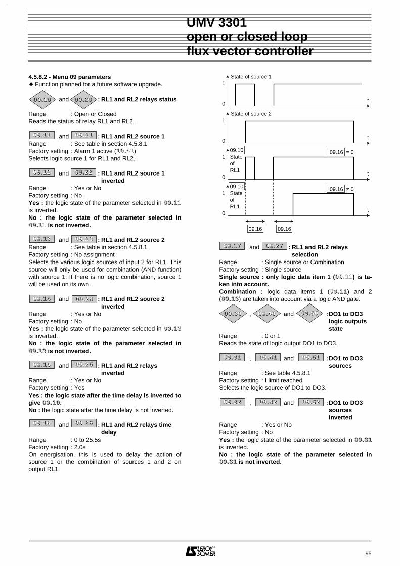
4.5.8.2 - Menu 09 parameters Function planned for a future software upgrade.
and : RL1 and RL2 relays status
Range : Open or ClosedReads the status of relay RL1 and RL2.
and : RL1 and RL2 source 1Range : See table in section 4.5.8.1Factory setting : Alarm 1 active (11 00 .. 44 11)Selects logic source 1 for RL1 and RL2.
and : RL1 and RL2 source 1inverted
Range : Yes or NoFactory setting : NoYes : the logic state of the parameter selected in 00 99 .. 11 11is inverted.No : rhe logic state of the parameter selected in00 99 .. 11 11 is not inverted.
and : RL1 and RL2 source 2Range : See table in section 4.5.8.1Factory setting : No assignmentSelects the various logic sources of input 2 for RL1. Thissource will only be used for combination (AND function)with source 1. If there is no logic combination, source 1will be used on its own.
and : RL1 and RL2 source 2inverted
Range : Yes or NoFactory setting : NoYes : the logic state of the parameter selected in 00 99 .. 11 33is inverted.No : the logic state of the parameter selected in00 99 .. 11 33 is not inverted.
and : RL1 and RL2 relays inverted
Range : Yes or NoFactory setting : YesYes : the logic state after the time delay is inverted togive 00 99 .. 11 00.No : the logic state after the time delay is not inverted.
and : RL1 and RL2 relays time delay
Range : 0 to 25.5sFactory setting : 2.0sOn energisation, this is used to delay the action ofsource 1 or the combination of sources 1 and 2 onoutput RL1.
and : RL1 and RL2 relays selection
Range : Single source or CombinationFactory setting : Single sourceSingle source : only logic data item 1 (00 99 .. 11 11) is ta-ken into account.Combination : logic data items 1 (00 99 .. 11 11) and 2(00 99 .. 11 33) are taken into account via a logic AND gate.
, and :DO1 to DO3logic outputsstate
Range : 0 or 1Reads the state of logic output DO1 to DO3.
, and :DO1 to DO3 sources
Range : See table 4.5.8.1Factory setting : I limit reachedSelects the logic source of DO1 to DO3.
, and :DO1 to DO3sourcesinverted
Range : Yes or NoFactory setting : NoYes : the logic state of the parameter selected in 00 99 .. 33 11is inverted.No : the logic state of the parameter selected in00 99 .. 33 11 is not inverted.
95
UMV 3301open or closed loopflux vector controller
t
State of source 11
0
t
State of source 21
0
t
09.10StateofRL1
09.16 = 01
0
t
09.10StateofRL1
09.16 = 01
0
09.1609.16
00 99 .. 11 11
00 99 .. 11 00
00 99 .. 11 22
00 99 .. 11 33
00 99 .. 11 44
00 99 .. 11 55
00 99 .. 22 00
00 99 .. 22 11
00 99 .. 22 22
00 99 .. 22 33
00 99 .. 22 44
00 99 .. 22 55
00 99 .. 11 66 00 99 .. 22 66
00 99 .. 11 77 00 99 .. 22 77
00 99 .. 33 00 00 99 .. 44 00 00 99 .. 55 00
00 99 .. 33 11 00 99 .. 44 11 00 99 .. 55 11
00 99 .. 33 22 00 99 .. 44 22 00 99 .. 55 22

, and :DO1 to DO3output time delay
Range : 0 to 25.5sFactory setting : 2.0sThis is used to delay the action of the logic source ofDO1 to DO3.
96
UMV 3301open or closed loopflux vector controller
t
DO1 source1
0
t
1
0
t
09.30DO1output
09.30DO1output
09.36 = 0
09.36 = 0
1
0
09.3609.36
00 99 .. 33 66 00 99 .. 44 66 00 99 .. 55 66
97
UMV 3301open or closed loopflux vector controller
NOTES
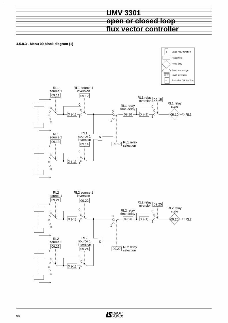
98
4.5.8.3 - Menu 09 block diagram (1)
UMV 3301open or closed loopflux vector controller
RL1source 1
RL1 source 1inversion
0
1
RL1source 2
RL1source 1inversion
0
1
09.11 09.12
09.1309.14
&
RL1 relayinversion
RL1 relaytime delay
RL1 relayselection
0
1
0
1
RL1 relaystate
RL1
09.17
09.15
09.1009.16 X (-1)X (-1)
X (-1)
RL2source 1
RL2 source 1inversion
0
1
RL2source 2
RL2source 1inversion
0
1
09.21 09.22
09.2309.24
&
RL2 relayinversion
RL2 relaytime delay
RL2 relay selection
0
1
0
1
RL2 relaystate
RL2
09.27
09.25
09.2009.26 X (-1)X (-1)
X (-1)
X(-1)
= 1
Read/write
Read-only
Read and assign
Logic inversion
Exclusive OR function
& Logic AND function
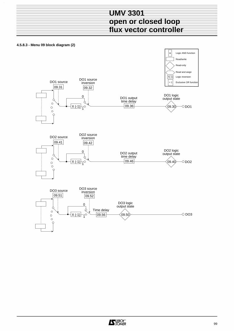
99
4.5.8.3 - Menu 09 block diagram (2)
UMV 3301open or closed loopflux vector controller
DO2 sourceDO2 source
inversion
0
1
DO2 outputtime delay
09.41 09.42
DO2 logicoutput state
DO3 sourceDO3 source
inversion
DO3 logicoutput state
DO209.46 09.40
0
1
09.51 09.52
DO309.50Time delay
09.56
X (-1)
DO1 sourceDO1 source
inversion
0
1
DO1 outputtime delay
09.31 09.32
DO1 logicoutput state
DO109.36 09.30X (-1)
X (-1)
X(-1)
= 1
Read/write
Read-only
Read and asign
Logic inversion
Exclusive OR function
& Logic AND function

100
UMV 3301open or closed loopflux vector controller
NOTES
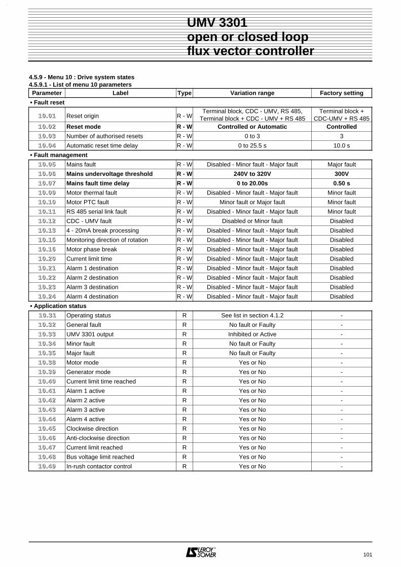
101
UMV 3301open or closed loopflux vector controller
4.5.9 - Menu 10 : Drive system states4.5.9.1 - List of menu 10 parametersParameter Label Type Variation range Factory setting
• Fault reset
11 00 .. 00 11 Reset origin R - WTerminal block, CDC - UMV, RS 485,
Terminal block + CDC - UMV + RS 485Terminal block +
CDC-UMV + RS 48511 00 .. 00 22 Reset mode R - W Controlled or Automatic Controlled
11 00 .. 00 33 Number of authorised resets R - W 0 to 3 3
11 00 .. 00 44 Automatic reset time delay R - W 0 to 25.5 s 10.0 s
• Fault management
11 00 .. 00 55 Mains fault R - W Disabled - Minor fault - Major fault Major fault
11 00 .. 00 66 Mains undervoltage threshold R - W 240V to 320V 300V
11 00 .. 00 77 Mains fault time delay R - W 0 to 20.00s 0.50 s
11 00 .. 00 99 Motor thermal fault R - W Disabled - Minor fault - Major fault Minor fault
11 00 .. 11 00 Motor PTC fault R - W Minor fault or Major fault Minor fault
11 00 .. 11 11 RS 485 serial link fault R - W Disabled - Minor fault - Major fault Minor fault
11 00 .. 11 22 CDC - UMV fault R - W Disabled or Minor fault Disabled
11 00 .. 11 33 4 - 20mA break processing R - W Disabled - Minor fault - Major fault Disabled
11 00 .. 11 55 Monitoring direction of rotation R - W Disabled - Minor fault - Major fault Disabled
11 00 .. 11 66 Motor phase break R - W Disabled - Minor fault - Major fault Disabled
11 00 .. 22 00 Current limit time R - W Disabled - Minor fault - Major fault Disabled
11 00 .. 22 11 Alarm 1 destination R - W Disabled - Minor fault - Major fault Disabled
11 00 .. 22 22 Alarm 2 destination R - W Disabled - Minor fault - Major fault Disabled
11 00 .. 22 33 Alarm 3 destination R - W Disabled - Minor fault - Major fault Disabled
11 00 .. 22 44 Alarm 4 destination R - W Disabled - Minor fault - Major fault Disabled
• Application status
11 00 .. 33 11 Operating status R See list in section 4.1.2 -
11 00 .. 33 22 General fault R No fault or Faulty -
11 00 .. 33 33 UMV 3301 output R Inhibited or Active -
11 00 .. 33 44 Minor fault R No fault or Faulty -
11 00 .. 33 55 Major fault R No fault or Faulty -
11 00 .. 33 88 Motor mode R Yes or No -
11 00 .. 33 99 Generator mode R Yes or No -
11 00 .. 44 00 Current limit time reached R Yes or No -
11 00 .. 44 11 Alarm 1 active R Yes or No -
11 00 .. 44 22 Alarm 2 active R Yes or No -
11 00 .. 44 33 Alarm 3 active R Yes or No -
11 00 .. 44 44 Alarm 4 active R Yes or No -
11 00 .. 44 55 Clockwise direction R Yes or No -
11 00 .. 44 66 Anti-clockwise direction R Yes or No -
11 00 .. 44 77 Current limit reached R Yes or No -
11 00 .. 44 88 Bus voltage limit reached R Yes or No -
11 00 .. 44 99 In-rush contactor control R Yes or No -

102
UMV 3301open or closed loopflux vector controller
4.5.9.1 - List of menu 10 parameters (continued)
Parameter Label Type Variation range Factory setting• Braking
11 00 .. 55 11 Brake control R Yes or No -11 00 .. 66 11 Timed low speed R Not reached or Reached -11 00 .. 66 22 Indexing completed R Yes or No -11 00 .. 66 33 Zero speed R Yes or No -
• Level of use11 00 .. 77 00 Motor use R 0 to 150 % -11 00 .. 77 55 Controller use R 0 to 150 % -11 00 .. 88 00 Braking resistor use R 0 to 150 % -
• 10 last faults stored11 00 .. 99 00 Fault - 9 R See list -11 00 .. 99 11 Fault - 8 R See list -11 00 .. 99 22 Fault - 7 R See list -11 00 .. 99 33 Fault - 6 R See list -11 00 .. 99 44 Fault - 5 R See list -11 00 .. 99 55 Fault - 4 R See list -11 00 .. 99 66 Fault - 3 R See list -11 00 .. 99 77 Fault - 2 R See list -11 00 .. 99 88 Fault - 1 R See list -11 00 .. 99 99 Fault - 0 R See list -
List of faults read from 11 00 .. 99 00 to 11 00 .. 99 99
Label LabelBus overvoltage Bus undervoltageOvercurrent Motor thermalCurrent imbalance Motor PTC probeController thermal RS 485 linkResistor thermal CDC - UMVInternal power supply 4 - 20mA breakProcessor Alarm 1 activeEncoder Alarm 2 activeEncoder break Alarm 3 activeProcessor option 1 Alarm 4 activeProcessor option 2 OverspeedExternal Current limit timeMains failure Ramp followingPhase missing IGBTMains undervoltage Direction of rotation errorMains overvoltage Motor phase break
None
From 180T rating upwards.

4.5.9.2 - Menu 10 parameters
: Reset originRange : Terminal block - CDC-UMV, RS 485
Terminal block or CDC-UMV or RS 485Factory setting : Terminal block or CDC-UMV or RS 485This is used to locate the position at which the manualfault reset is to be performed.
: Reset modeRange : Controlled or AutomaticFactory setting : ControlledAutomatic : if a run command is present, the motorrestarts without external intervention. If the fault persists,the controller will perform the number of resets selectedin 11 00 .. 00 33 before locking.Controlled : the reset must be performed manually atthe location selected in 11 00 .. 00 11.
Note : It is helpful to set 11 00 .. 00 22 = Automatic, so that therun command does not have to be switched.
: Number of authorised resetsRange : 0 to 3Factory setting : 3Limits the number of fault reset attempts (see 11 00 .. 00 22). If,after a period of 5 min, no fault occurs, the number ofattempts is incremented by 1 within the limit of 11 00 .. 00 33.
: Time delay before resetRange : 0 to 25.5sFactory setting : 10.0sIs used to set the period between triggering of the faultand the automatic reset request.
: Mains faultRange : Disabled - Minor fault - Major faultFactory setting : Major faultThis is used to select the importance or the impact of amains fault according to the application. See 11 00 .. 00 66Detection threshold.Disabled : the fault is detected, but has no consequenc-es.Minor fault : the fault causes a stop according to theselection made in 0066..6644.Major fault : the fault causes a freewheel stop.See parameter 11 00 .. 00 77.
: Mains undervoltage thresholdRange : 240 to 320VFactory setting : 300VSets the mains voltage level for which the controller willdetect an undervoltage fault.
: Time delay before mains faultRange : 0 to 20.00sFactory setting : 0.50sIs used to delay the action of a « mains fault ».See parameter 11 00 .. 00 55.
: Motor thermal faultRange : Disabled - Minor fault - Major faultFactory setting : Minor faultThis is used to select the importance or the impact of amotor thermal fault. See 11 00 .. 00 55.
: Motor PTC faultRange : Minor fault or Major faultFactory setting : Minor faultThis is used to select the importance or the impact of aPTC fault (up to 3 PTCs in series). See 11 00 .. 00 55.
: Serial link faultRange : Disabled - Minor fault - Major faultFactory setting : Minor faultThis is used to select the importance or the impact of aserial link fault. See 11 00 .. 00 55.
: CDC - UMV faultRange : Disabled or Minor faultFactory setting : DisabledCommunication fault between the controller and theconsole. See 11 00 .. 00 55.
: 4-20mA faultRange : Disabled - Minor fault - Major faultFactory setting : DisabledThis is used to select the importance or the impact of a4/20mA analogue reference break fault. See 11 00 .. 00 55.
: Monitoring the direction of rotationRange : Disabled - Minor fault - Major faultFactory setting : DisabledIs used to cause a fault when the motor is not turning inthe required direction. See the processing in 11 00 .. 00 55.
: Motor phase breakRange : Disabled - Minor fault - Major faultFactory setting : DisabledIs used to monitor the connections between the motorand the controller. See the processing in 11 00 .. 00 55.
: Current limit time processingRange : Disabled - Minor fault - Major faultFactory setting : DisabledProcessing of the fault detected by 11 00 .. 44 00. See 11 00 .. 00 55.
to : Destination of alarms 1 to 4Range : Disabled - Minor fault - Major faultFactory setting : DisabledThe state of the 4 alarms in menu 5 may cause a faultwhose impact is set here. See 11 00 .. 00 55.
: Operating status
This is used to read the status of the controller when it isstopped or running. See list in section 4.1.2.
103
UMV 3301open or closed loopflux vector controller
11 00 .. 00 11
11 00 .. 33 11
11 00 .. 00 22
11 00 .. 00 33
11 00 .. 00 44
11 00 .. 00 55
11 00 .. 00 66
11 00 .. 00 77
11 00 .. 00 99
11 00 .. 11 00
11 00 .. 11 11
11 00 .. 11 22
11 00 .. 11 33
11 00 .. 11 55
11 00 .. 11 66
11 00 .. 22 00
11 00 .. 22 11 11 00 .. 22 44

: General fault
Range : No fault or FaultyWhatever the origin or type of a fault, 11 00 .. 33 22 indicateswhether or not a fault is present.
: UMV 3301 output
Range : Inhibited or ActiveInhibited : the controller does not supply any energy,because it has not received a command or is faulty.Active : the controller supplies energy to the motor.
: Minor fault
Range : No fault or FaultyFaulty : one of the faults (11 00 .. 00 55 to 11 00 .. 22 44) has beendeclared minor and has tripped.No fault : no fault declared as minor has tripped.
: Major fault
Range : No fault or FaultyFaulty : one of the faults (11 00 .. 00 55 to 11 00 .. 22 44) has beendeclared major and has tripped.No fault : no fault declared as major has tripped.
: Motor mode
Range : Yes or NoYes : the motor is driving the load. Operation is takingplace in quadrant 1 or 3. In read mode, M is displayed.No : the motor is stopped or in generator mode.
: Generator mode
Range : Yes or NoYes : the motor is driving the load (braking inertia, etc).Operation is taking place in quadrant 2 or 4. In readmode, G is displayed.No : the motor is stopped or in motor mode.
: Current limit time reached
Range : Yes or NoYes : the current has been limited for longer than thetime in 00 55 .. 00 22, causing a fault according to 11 00 .. 22 00.No : the time set in 00 55 .. 00 22 has not been reached.
to : Alarm 1 to 4 active
Range : Yes or NoYes : the corresponding alarm threshold has beenreached (menu 5 level) and triggers a fault according to11 00 .. 22 11 to 11 00 .. 22 44.No : no alarm has been detected in menu 5.
: Clockwise direction
Range : Yes or NoYes : the direction of rotation of the motor viewed fromthe shaft end is clockwise. In read mode, isdisplayed.No : the motor is rotating anti-clockwise.
: Anti-clockwise direction
Range : Yes or NoYes : the direction of rotation of the motor viewed fromthe shaft end is anti-clockwise. In read mode isdisplayed.No : the motor is rotating clockwise.
: Current limit reached
Range : Yes or NoYes : the current request is higher than current limit00 44 .. 33 00 when there is an overload or a transient. Thecontroller is no longer in speed regulation and the over-load integration is beginning to take effect.No : limit 00 44 .. 33 00 has not been reached.
: Bus voltage limit reached
Range : Yes or NoYes : the DC bus voltage limit 00 44 .. 77 11 has been reachedbecause the load is driving the motor too fast (backdriv-ing) or the deceleration is too fast.No : the DC bus voltage remains below the value of 0044..7711.
: In-rush contactor control
Range : Yes or NoYes : the DC bus in-rush contactor is energised.No : the DC bus in-rush contactor is not energised.
: Brake control
Range : Yes or NoYes : the electromechanical brake mounted on the motoror the application is controlled. See 0066..5500 to 0066..5544.No : the brake is not controlled.
: Timed low speed
Range : Not reached or ReachedReached : at a stop command, the motor speed hasdecreased to settle at the low speed set via 00 66 .. 77 11 forthe period set via 00 66 .. 77 22.Not reached : at a stop command, the motor is in thedeceleration phase.
104
UMV 3301open or closed loopflux vector controller
11 00 .. 33 22
11 00 .. 33 33
11 00 .. 33 44
11 00 .. 33 55
11 00 .. 33 88
11 00 .. 33 99
11 00 .. 44 00
11 00 .. 44 11 11 00 .. 44 44
11 00 .. 44 55
11 00 .. 44 66
11 00 .. 44 77
11 00 .. 44 88
11 00 .. 44 99
11 00 .. 55 11
11 00 .. 66 11

: Indexing completed
Range : Yes or NoYes : at an indexed stop (in closed loop operation only)DI5 has issued the indexing completed data bit.No : DI5 has not issued the indexing completed data bit.
: Zero speed
Range : Yes or NoYes : the motor speed is close to zero (loop open) or atzero (loop closed).No : the motor speed is other than zero.
: Motor use
Range : 0 to 150 %Indicates the output power level supplied via the motor.
: Controller use
Range : 0 to 150 %Indicates the level of stress on the controller.
: Braking resistor use
Range : 0 to 150 %Indicates the level of stress on the optional brakingresistor as a function of 00 66 .. 55 88 and 00 66 .. 55 99.
to : Reading the last 10 storedfaults
The faults are displayed as they appear from 11 00 .. 99 00 to11 00 .. 99 99. The display is stored as long as there are nomore than 10 faults. Then, as new faults appear, theoldest ones are deleted. The chronological order isalways observed (eg. : 11 00 .. 99 00 always displays the oldestfault, and 1100..9999 the most recent one stored).See list of faults in section 4.5.9.1 and their meanings insection 5.2.
105
UMV 3301open or closed loopflux vector controller
11 00 .. 66 22
11 00 .. 66 33
11 00 .. 77 00
11 00 .. 77 55
11 00 .. 88 00
11 00 .. 99 00 11 00 .. 99 99

106
4.5.9.3 - Menu 10 block diagram (1)
UMV 3301open or closed loopflux vector controller
automatic
controlled
1
0
• Reset
• Number of authorised resets
• Automatic time delay before reset
10.03
10.04
FAULT PROCESSING
10.02
Thermal block" RESET " input
CDC UMV " RESET " key
All sources
Serial link
• Command source
FAULT MANAGEMENT
CLEAR FAULTMANAGEMENT
CLEAR FAULTCOMMAND 10.01
• Mains fault
• Mains undervoltage threshold
• Time delay before mains fault
• Motor thermal fault
• Motor PTC fault
• RS 485 serial link fault
• CDC-UMV fault
• 4/20mA break
• Direction of rotation monitoring
• Motor phase break
• Current limit time fault
• Channel 1 destination
• Channel 2 destination
• Channel 3 destination
• Channel 4 destination
10.07
10.05
10.06
10.09
10.10
10.11
10.12
10.13
10.15
10.16
10.20
10.21
10.22
10.23
10.24

107
4.5.9.3 - Menu 10 block diagram (2)
UMV 3301open or closed loopflux vector controller
• Operating status
• General fault
• UMV 3301 output inhibited/active
• Minor fault
• Major fault
• Motor operating
• Generator operating
• Current limit time reached
SIGNALLING
10.31
10.32
10.33
10.34
10.35
10.38
10.39
10.40
• Channel 1 output state
• Channel 2 output state
• Channel 3 output state
• Channel 4 output state
• Clockwise operation
• Anti-clockwise operation
• Current limiting
• DC bus voltage limiting
• Control of preloading contractor
10.41
10.42
10.43
10.44
10.45
10.46
10.47
10.48
10.49
• Last fault : 0
• Fault - 1
• Fault - 2
• Fault - 3
• Fault - 4
10.99
10.98
10.97
10.96
10.95
• Fault - 5
• Fault - 6
• Fault - 7
• Fault - 8
• Fault - 9
10.94
10.93
10.92
10.91
10.90
• Brake control
• Timed low speed
10.51
10.61
• Indexing completed
• Zero speed (<10 min )
10.62
10.63-1
• Motor(%)
APPLICATIONSTATUS
LAST 10 FAULTSMEMORIZED
BRAKING
OPERATING RATE
10.70
• Speed controller (%) 10.75
• Braking resistor (%) 10.80

108
UMV 3301open or closed loopflux vector controller
NOTES

109
UMV 3301 open or closed loopflux vector controller
4.5.10 - Menu 11 : User menu parameters
Range : 00 11 .. 00 11 to 11 77 .. 99 99.Factory setting : see below.The menu 11 parameters are used for programming parameters from any menu in the user menu. With the factory setting, the most commonly used parameters are assigned in the user menu. For special applications, usefulparameters can be assigned to the user menu via menu 11.Eg. : If 11 11 .. 00 44 = 11 44 .. 44 11, the PID proportional gain (11 44 .. 44 11) can be set in the user menu.
Factory setting of the menu 11 parameters
11 11 .. 00 11 11 11 .. 33 22 to
Parameter Factory setting
11 11 .. 00 11 00 22 .. 55 00 CDC - UMV speed reference
11 11 .. 00 22 00 22 .. 00 22 Speed reference source
11 11 .. 00 33 00 66 .. 00 11 Control source
11 11 .. 00 44 00 66 .. 00 33 Starting
11 11 .. 00 55 11 00 .. 00 22 Reset mode
11 11 .. 00 66 00 66 .. 00 55 Flying restart
11 11 .. 00 77 11 00 .. 00 66 Mains undervoltage threshold
11 11 .. 00 88 11 00 .. 00 77 Time delay before mains fault
11 11 .. 00 99 00 77 .. 11 77 AI1 100 % calibration
11 11 .. 11 00 00 77 .. 33 66 Selection of setpoint type on AI3
11 11 .. 11 11 00 77 .. 33 33 AI3 0 % calibration
11 11 .. 11 22 00 77 .. 33 44 Ana input 3 Remote scaling
11 11 .. 11 33 00 22 .. 22 11 PS1
11 11 .. 11 44 00 22 .. 22 22 PS2
11 11 .. 11 55 00 22 .. 22 33 PS3
11 11 .. 11 66 00 22 .. 88 11 Minimum limit
11 11 .. 11 77 00 22 .. 88 33 Maximum limit
11 11 .. 11 88 00 22 .. 99 11 Skip speed 1
11 11 .. 11 99 00 22 .. 99 44 Skip band 1
11 11 .. 22 00 00 22 .. 77 00 Forward/Reverse enabled
11 11 .. 22 11 00 33 .. 11 00 Acceleration ramp
11 11 .. 22 22 00 33 .. 33 00 Deceleration ramp
11 11 .. 22 33 00 77 .. 22 99 AI2 input destination
11 11 .. 22 44 00 77 .. 22 77 Ana input 2 Local scaling
11 11 .. 22 55 00 44 .. 33 66 Current limit
11 11 .. 22 66 00 55 .. 11 22 RL1 output minimum speed threshold
11 11 .. 22 77 00 55 .. 22 22 DO3 output maximum speed threshold
11 11 .. 22 88 00 77 .. 55 22 Type of AO1 output signal
11 11 .. 22 99 00 77 .. 55 77 Maximum current value on AO1
11 11 .. 33 00 00 77 .. 66 22 AO2 output signal type
11 11 .. 33 11 00 77 .. 66 77 AO2 output maximum speed value
11 11 .. 33 22 00 44 .. 00 44 Stability

110
UMV 3301open or closed loopflux vector controller
NOTES

111
UMV 3301 open or closed loopflux vector controller
4.5.11 - Menu 12 : Programmable thresholds4.5.11.1 - List of menu 12 parameters
Parameter Label Type Variation range Factory setting
11 22 .. 00 11 Threshold No. 1 overshoot R Yes or No -
11 22 .. 00 22 Threshold No. 2 overshoot R Yes or No -
11 22 .. 11 11 Threshold No. 1 source R - W See table 00 44 .. 00 11
11 22 .. 11 22 Threshold No. 1 level R - W ± 9999 9999
11 22 .. 11 33 Threshold No. 1 hysteresis R - W 2 to 255 2
11 22 .. 11 44 Threshold No. 1 inversion R - W Yes or No No
11 22 .. 11 55 Threshold No. 1 destination R - W See table None
11 22 .. 22 11 Threshold No. 2 source R - W See table 00 44 .. 00 11
11 22 .. 22 22 Threshold No. 2 level R - W ± 9999 9999
11 22 .. 22 33 Threshold No. 2 hysteresis R - W 2 to 255 2
11 22 .. 22 44 Threshold No. 2 inversion R - W Yes or No No
11 22 .. 22 55 Threshold No. 2 destination R - W See table None
Source of programmable thresholds (11 22 .. 11 11, 11 22 .. 22 11)
Parameter Label Parameter Label
- No assignment 00 77 .. 11 00 AI1 reading (%)
00 22 .. 00 11 Speed reference before ramp 00 77 .. 11 88 AI1 final value
00 22 .. 88 00 Reference before limiting 00 77 .. 22 00 AI2 reading (%)
00 33 .. 00 11 Final speed reference 00 77 .. 22 88 AI2 final value
00 44 .. 00 11 Speed measurement 00 77 .. 33 00 AI3 reading (%)
00 44 .. 00 22 Speed error 00 77 .. 33 88 AI3 final value
00 44 .. 00 66 Speed reachel error 00 77 .. 44 00 AI4 reading (%)
00 44 .. 22 00 Final torque reference 00 77 .. 77 00 Motor voltage
00 44 .. 44 00 Active current reference 00 77 .. 88 00 Motor power
00 44 .. 44 22 Total motor current 11 00 .. 77 00 Motor use
00 44 .. 44 44 Active motor current 11 00 .. 77 55 Controller use
00 44 .. 55 00 Motor torque 11 00 .. 88 00 Braking resistor use
00 44 .. 66 00 Motor frequency 11 44 .. 00 11 PID output
00 44 .. 77 00 Motor voltage 11 44 .. 22 00 PID final reference
00 44 .. 88 00 Motor power 11 44 .. 33 00 PID feedback
00 44 .. 88 11 Energy 1 (MW.h) 11 44 .. 44 00 PID error
00 44 .. 88 22 Energy 2 (KW.h) 11 55 .. 11 00 Customer torque
00 44 .. 99 00 Encoder frequency 11 66 .. 00 66 Voltage error
00 44 .. 99 22 Remanent frequency

112
UMV 3301 open or closed loopflux vector controller
Assigment of programmable thresholds (11 22 .. 11 55 and 11 22 .. 22 55)
Parameter Label Parameter Label
- No assignment 00 33 .. 55 00 Special ramp type
00 11 .. 44 22 Operational setting 00 44 .. 11 11 Control type
00 22 .. 00 22 Speed reference source 00 44 .. 11 22 Zero torque selection
00 22 .. 00 33 RS 485 reference enabled 00 44 .. 11 44 Torque offset selection
00 22 .. 11 44 Ref. No. 1 / No. 2 selection 00 44 .. 33 33 Limit 1 or limit 2 enable
00 22 .. 11 55 Summing 00 44 .. 44 66 Energy saver
00 22 .. 11 77 1 PS selected 00 66 .. 44 22 Flux at stop
00 22 .. 11 88 3 PS selected 00 66 .. 66 11 Stop command 1
00 22 .. 11 99 7 PS selected 00 77 .. 11 22 AI1 offset selection
00 22 .. 33 11 Faster function 00 77 .. 22 22 AI2 offset selection
00 22 .. 33 22 Slower function 00 77 .. 33 55 AI3 input inversion
00 22 .. 33 33 Faster/slower function 11 33 .. 11 11 Inhibit MODBUS control
00 22 .. 44 33 Jogging 11 44 .. 11 77 1 PID RP selection
00 22 .. 77 00 Forward/Reverse 11 44 .. 11 88 3 PID RP selection
00 33 .. 00 55 S ramp selection 11 44 .. 44 66 Integral locked
00 33 .. 00 77 Ramp locking 11 44 .. 44 88 PID output summing
00 33 .. 00 88 Ramp by-pass 11 44 .. 55 00 PID enabled
00 33 .. 11 77 1 ACCP selection 11 55 .. 11 11 HSP enabled
00 33 .. 11 88 3 ACCP selection 11 55 .. 11 66 No-lead overspeed
00 33 .. 33 77 1 DECP selection 11 55 .. 22 22 Low speed request
00 33 .. 33 88 3 DECP selection 11 66 .. 22 00 Preload contactor OK

4.5.11.2 - Menu 12 parameters
: Threshold No. 1 overshoot
Range : Yes or NoYes : the threshold set in 11 22 .. 11 11 has been exceeded.No : the threshold set in 11 22 .. 11 11 has not been reached.
: Threshold No. 2 overshoot
Range : Yes or NoYes : the threshold set in 11 22 .. 22 11 has been exceeded.No : the threshold set in 11 22 .. 22 11 has not been reached.
: Threshold No. 1 sourceRange : See table in section 4.5.11.1Factory setting : Speed measurement (00 44 .. 00 11)This is used to select the source of the variable to becompared with the threshold set in 11 22 .. 11 22.
: Threshold No. 1 levelRange : ± 9999Factory setting : 9999For setting the required threshold as a function of 11 22 .. 11 11.
: Threshold No. 1 hysteresisRange : 2 to 255Factory setting : 2Prevents « triggering » around the setting threshold.
: Threshold No. 1 inversionRange : Yes or NoFactory setting : NoYes : the logic state of 11 22 .. 00 11 is inverted before itsassignment by 11 22 .. 11 55.No : the logic state of 11 22 .. 00 11 is not inverted.
: Threshold No. 1 destinationRange : See table in section 4.5.11.1Factory setting : NoneIs used to select the address which will receive thethreshold No. 1 exceeded information.
: Threshold No. 2 sourceRange : See table in section 4.5.11.1Factory setting : Speed measurement (00 44 .. 00 11)This is used to select the source of the variable to becompared with the threshold set in 11 22 .. 22 22.
: Threshold No. 2 levelRange : ± 9999Factory setting : 9999For setting the required threshold as a function of 11 22 .. 22 11.
: Threshold No. 2 hysteresisRange : 2 to 255Factory setting : 2Prevents « triggering » around the setting threshold.
: Threshold No. 2 inversionRange : Yes or NoFactory setting : NoYes : the logic state of 11 22 .. 00 22 is inverted before its as-signment by 11 22 .. 22 55.No : the logic state of 11 22 .. 00 22 is not inverted.
: Threshold No. 2 destinationRange : See table in section 4.5.11.1Factory setting : NoneIs used to select the address which will receive thethreshold No. 2 exceeded information.
113
UMV 3301 open or closed loopflux vector controller
11 22 .. 11 11
11 22 .. 00 11
11 22 .. 00 22
11 22 .. 11 22
11 22 .. 11 33
11 22 .. 11 44
11 22 .. 11 55
11 22 .. 22 11
11 22 .. 22 22
11 22 .. 22 33
11 22 .. 22 44
11 22 .. 22 55

114
UMV 3301 open or closed loopflux vector controller
4.5.11.3 - Menu 12 block diagram
ThresholdN° 1 destination
ThresholdN° 1 hysteresis
ThresholdN° 1 overshoot
ThresholdN° 1 level
Threshold N° 1 source
ThresholdN° 1 inversion
ThresholdN° 2 destination
ThresholdN° 2 hysteresis
ThresholdN° 2 overshoot
ThresholdN° 2 level
ThresholdN° 2 source
ThresholdN° 2 inversion
0
1+
-
12.11
12.12
12.13 12.14
X (-1)
12.15
0
1+
-
12.21
12.22
12.23 12.24
12.25
12.01
12.02X (-1)
X(-1)
= 1
Read/write
Read-only
Read and assign
Logic inversion
Exclusive OR function
& Logic AND function

4.5.12.2 - Menu 13 parameters
: Serial link addressRange : 1 to 32Factory setting : 11Address of the controller when it is communicating with aPC or PLC.
: SpeedRange : 2400 - 4800, 9600, 19200 baudsFactory setting : 9600 baudsSpeed of data transmission via the serial link.
: ParityRange : No parity - Even - OddFactory setting : OddSelection of the structure of the serial link messages foreither PC or PLC.
: Serial link monitoringRange : Yes or NoFactory setting : NoYes : enables monitoring of serial link operation by themicroprocessor.No : no monitoring of the serial link.
: Monitoring periodRange : 0 to 999Factory setting : 10For setting the monitoring periodicity when 11 33 .. 00 44 = yes.
: Serial link self-testRange : Yes or NoFactory setting : NoYes : enables a serial link self-test each time the control-ler is powered up.No : no automatic self-test on each power-up.
: Self-test result
Range : None - OK - ErrorReport on the serial link self-test if 11 33 .. 00 66 = yes.
: Parameter-setting modeRange : Locked, MODBUS, CDC-UMV,
MODBUS or CDC-UMVFactory setting : CDC-UMVLocked : no parameter can be modified.MODBUS : the parameters can only be modified via theserial link.CDC-UMV : the parameters can only be modified viathe console.MODBUS or CDC-UMV : the parameters can be modi-fied via the serial link or the console.
: MODBUS controlRange : MODBUS only, MODBUS or
Terminal block, MODBUS or CDC-UMVFactory setting : MODBUS onlyMODBUS only : when 00 66 .. 00 11 = MODBUS, commandscan only be given via the serial link.MODBUS or CDC-UMV : when 00 66 .. 00 11 = MODBUS,commands are given via the serial link or the keypad.MODBUS or terminal block : when 00 66 .. 00 11 = MODBUS,commands are given via the serial link or the terminalblock.WARNING : This parameter is available only when 00 66 .. 00 11 is set toRS485.
: Inhibit MODBUS controlRange : Yes or NoFactory setting : NoNo : commands via MODBUS are active.Yes : commands via MODBUS are not taken intoaccount.Note : 11 33 .. 11 11 can be assigned to a logic input.
115
UMV 3301 open or closed loopflux vector controller
4.5.12 - Menu 13 : Serial link4.5.12.1 - List of menu 13 parameters
Parameter Label Type Variation range Factory setting
11 33 .. 00 11 Serial link address R - W 1 to 32 11
11 33 .. 00 22 Speed R - W 2400 - 4800 - 9600 - 19200 bauds 9600 bauds
11 33 .. 00 33 Parity R - W No parity - Even - Odd Odd
11 33 .. 00 44 Serial link monitoring R - W Yes or No No
11 33 .. 00 55 Monitoring period R - W 0 to 999 10
11 33 .. 00 66 Serial link self-test R - W Yes or No No
11 33 .. 00 77 Self-test result R None - OK - Error -
11 33 .. 00 88 Parameter-setting mode R - WLocked, MODBUS, CDC-UMV
MODBUS or CDC-UMV CDC-UMV
11 33 .. 11 00 MODBUS control R - WMODBUS, MODBUS or Term. blk
MODBUS or CDC-UMV MODBUS
11 33 .. 11 11 Inhibit MODBUS control R - W Yes or No No
11 33 .. 00 1111 33 .. 00 77
11 33 .. 00 22
11 33 .. 00 33
11 33 .. 00 44
11 33 .. 00 55
11 33 .. 00 66
11 33 .. 00 88
11 33 .. 11 00
11 33 .. 11 11

116
UMV 3301 open or closed loopflux vector controller
4.5.12.3 - Menu 13 block diagram
13.02 13.03
13.07
Rx
Rx
Tx
Tx
Seriallink
No NoYes Yes
13.01
13.0413.05
13.08 Lockparameters
Lockcontrol
13.11
13.10
13.06
Address Speed Parity
Monitoringperiod Self-test
result
Parametersetting mode
MODBUScontrol
Inhibit MODBUS control
Monitoring Self-test
X(-1)
= 1
Read/write
Read-only
Read and assign
Logic inversion
Exclusive OR function
& Logic AND function

117
UMV 3301 open or closed loopflux vector controller
4.5.13 - Menu 14 : PID controller4.5.13.1 - List of menu 14 parameters
Parameter Label Type Variation range Factory setting
11 44 .. 00 11 PID output R ±32000 -
11 44 .. 11 00 Analogue PID reference R ± 8192
11 44 .. 11 77 1 PID reference selection R - A 0 or 1 -
11 44 .. 11 88 3 PID reference selection R - A 0 or 1 -
11 44 .. 22 00 PID final reference R ±32000 -
11 44 .. 22 11 Programmable PID reference 1 R - W ±32000 0
11 44 .. 22 22 Programmable PID reference 2 R - W ±32000 0
11 44 .. 22 33 Programmable PID reference 3 R - W ±32000 0
11 44 .. 22 55 PID ramp R - W 0 to 3200.0s-1 600.0
11 44 .. 33 00 PID feedback R ±32000 -
11 44 .. 33 11 PID feedback inversion R - W Yes or No No
11 44 .. 33 22 PID feedback source R - W See table -
11 44 .. 44 00 PID error R ±32000 -
11 44 .. 44 11 PID proportional gain R - W 0 to 999 10
11 44 .. 44 22 PID integral gain R - W 0 to 999 10
11 44 .. 44 33 PID derivative gain R - W 0 to 10 0
11 44 .. 44 44 PID low limit R - W ±32000 0
11 44 .. 44 55 PID high limit R - W ±32000 +8000
11 44 .. 44 66 PID integral locked R - W Yes or No No
11 44 .. 44 77 Scaling of PID output R - W 0.01 to 10.00 1.00
11 44 .. 44 88 PID output summing R - W Yes or No No
11 44 .. 44 99 PID additionnal reference R - W ± 32000 0
11 44 .. 55 00 PID enabled R - W Yes or No No
11 44 .. 55 11 Programmable condition R - W See table Always enabled
11 44 .. 55 22 Programmable condition inversion R - W Yes or No No
11 44 .. 55 33 PID status RO Locked or Unlocked -
11 44 .. 66 00 PID destination R - W See table None
PID feedback source list (11 44 .. 33 22)
Parameter Label Parameter Label
- None 00 44 .. 88 00 Active motor power
00 44 .. 00 11 Speed measurement 00 44 .. 99 00 Encoder frequency
00 44 .. 22 00 Final torque reference 00 77 .. 11 88 AI1 final value
00 44 .. 44 00 Active current reference 00 77 .. 22 88 AI2 final value
00 44 .. 44 22 Total current measurement 00 77 .. 33 88 AI3 final value
00 44 .. 44 44 Active current measurement 00 77 .. 88 00 DC bus voltage
00 44 .. 55 00 Motor torque 11 00 .. 77 00 Motor use
00 44 .. 66 00 Motor frequency 11 00 .. 77 55 Controller use
00 44 .. 77 00 Motor voltage 11 00 .. 88 00 Braking resistor use

Source of PID controller (11 44 .. 55 11)
4.5.13.2 - Menu 14 parameters
: PID output
Range : ± 32000Reads the PID output after scaling.
: Analogue PID referenceRange : ± 8192Analogue PID reference from a programmable analogueinput.
: 1 PID reference selection Range : 0 or 1Reads the selection state. The state is changed by assi-gning 11 44 .. 11 77 to a programmable logic input.
: 3 PID reference selection Range : 0 or 1Reads the selection state. The state is changed by assi-gning 11 44 .. 11 88 to to a programmable logic input.
: Final PID reference
Range : ± 32000Reads, after selection, the PID reference and the ramp.
: Programmable PID reference 1Range : ± 32000Factory setting : 0For setting the numeric value of the PID 1 reference.
PID feedback assigment list (11 44 .. 66 00)
: Programmable PID reference 2Range : ± 32000Factory setting : 0For setting the numeric value of the PID 2 reference.
: Programmable PID reference 3Range : ± 32000Factory setting : 0For setting the numeric value of the PID 3 reference.
: PID rampRange : 0 to 3200s-1
Factory setting : 600s-1
All the PID references can be subject to a special rampset via 11 44 .. 22 55.
: PID feedback
Range : ± 32000Reads the PID feedback signal from a programmableanalogue input.
: PID feedback inversionRange : Yes or NoFactory setting : NoYes : the polarity of the PID feedback signal is inverted.No : the PID feedback is unchanged.
: PID feedback sourceRange : See table § 4.5.13.1Factory setting : NoneDefine the parameter which will be used as the PID feed-back.
118
UMV 3301 open or closed loopflux vector controller
Parameter Label
- None
00 22 .. 11 11 Speed reference No. 1
00 22 .. 11 22 Speed reference No. 2
00 22 .. 11 33 Additional speed reference
00 22 .. 88 33 Maximum limit clockwise
00 33 .. 00 33 Additional reference without ramp
00 44 .. 11 00 Torque reference
00 44 .. 11 33 Torque offset
00 44 .. 33 44 Motor torque 1 limit
00 44 .. 33 66 Motor torque 2 limit
00 44 .. 33 77 Torque limit in generator mode
00 44 .. 66 99 Motor speed adaptation threshold
11 66 .. 00 22 DC bus reference
Parameter Label
- Always enabled
11 00 .. 44 11 Alarm 1 active
11 00 .. 44 22 Alarm 2 active
11 00 .. 44 33 Alarm 3 active
11 00 .. 44 44 Alarm 4 active
11 22 .. 00 11 Threshold No. 1 overshoot
11 22 .. 00 22 Threshold No. 2 overshoot
11 44 .. 22 11
11 44 .. 00 11
11 44 .. 11 00
11 44 .. 11 77
11 44 .. 11 88
11 44 .. 22 00
11 44 .. 22 22
11 44 .. 22 33
11 44 .. 22 55
11 44 .. 33 11
11 44 .. 33 22
11 44 .. 33 00

: PID error
Range : ± 32000Reads the PID error after summing the PID referenceand the PID feedback.
: PID proportional gainRange : 0 to 999Factory setting : 10For setting the proportional gain of the PID loop.
: PID integral gainRange : 0 to 999Factory setting : 10For setting the integral gain of the PID loop. 11 44 .. 11 22 canbe locked by 11 44 .. 44 66.
: PID derivative gainRange : 0 to 10Factory setting : 0For setting the derivative gain of the PID loop.
: PID low limitRange : ± 32000Factory setting : 0For setting the minimum PID output value before scaling.The low limit can be assigned to a threshold (see menu12) which can be used externally by programming a logicoutput (see menu 09).
: PID high limitRange : ± 32000Factory setting : + 8000For setting the maximum PID output value before scaling.The high limit can be assigned to a threshold (see menu12) which can be used externally by programming a logicoutput (see menu 09).
: PID integral lockedRange : Yes or NoFactory setting : NoYes : the value of 11 44 .. 44 22 is not taken into account. Thislocking can be assigned externally if it is assigned to aprogrammable logic input.No : the value of 11 44 .. 44 22 is taken into account.
: PID output scalingRange : 0.01 to 10.00Factory setting : 1.00This adjustable coefficient is used to adapt the final PIDsignal with respect to its use depending on how it hasbeen assigned.
: PID output summingRange : Yes or NoFactory setting : NoYes : a reference set in 11 44 .. 44 99 is added to the PID out-put.No : there is no additionnal reference to the PID out-put.
: PID additionnal referenceRange : ± 32000Factory setting : 0Used to set the reference which is added to the PID out-put when 11 44 .. 44 88 is enabled.
: PID enabledRange : Yes or NoFactory setting : NoYes : the PID function is active.No : the PID function is inactive.
: Programmable conditionRange : See table § 4.5.13.1Factory setting : Always enabledUsed to select a PID function enable source.
: Programmable condition inversionRange : Yes or NoFactory setting : NoUsed to invert the signal from the source selected via11 44 .. 55 11.Yes : the logic state resulting from the selection in11 44 .. 55 11 is inverted.No : the logic state resulting from the selection in11 44 .. 55 11 is not inverted.
: PID status
Range : Locked or UnlockedReads the action condition of the PID function subject to11 44 .. 55 00 and to 11 44 .. 55 11.Locked : the PID function is inactive as either the UMVis locked (11 00 .. 33 33), or 11 44 .. 55 00 = no, or programmablecondition 11 44 .. 55 11 has not been given.Unlocked : the PID function is active.
: PID destinationRange : See table § 4.5.13.1Factory setting : No assignmentUsed to optionally select the assignment of the PIDfunction to a reference.WARNING : PID is disabled when 11 44 .. 66 00 is not programmed.
119
UMV 3301 open or closed loopflux vector controller
11 44 .. 44 11
11 44 .. 44 00
11 44 .. 44 22
11 44 .. 44 33
11 44 .. 44 44
11 44 .. 44 55
11 44 .. 44 66
11 44 .. 44 77
11 44 .. 44 88
11 44 .. 44 99
11 44 .. 55 00
11 44 .. 55 11
11 44 .. 55 22
11 44 .. 55 33
11 44 .. 66 00

120
UMV 3301 open or closed loopflux vector controller
4.5.13.3 - Menu 14 block diagram
14.5
1
K
= 1
4.41
K
= 1
4.42
K
= 1
4.43
low
: 14
.44
high
: 14
.45
14.5
0
14.2
2
14.2
314
.46
14.4
7R
P2
RP
1
RP
3
PID
feed
back
PID
unlo
cked
sta
te
Pro
gram
mab
leco
nditi
on in
vers
ion
Pro
gram
mab
le c
ondi
tion
14.6
0
PID
des
tinat
ion
PID
enab
led
14.2
1
1RP
3RP
PID
fina
lre
fere
nce
Ram
p
14.2
5
PID
err
or
PID
inte
gral
lock
ed
PID
feed
back
inve
rsio
nP
ID fe
edba
ckso
urce
Sca
ling
Lim
its
14.4
014
.20
PID
out
put
14.0
1
-
+p DI
14.5
2
14.5
3
14.1
714
.18
14.1
0
Ana
logu
ere
fere
nce
&10
.33
Lock
UM
V
X (
-1)
X(-
1)
= 1
Rea
d/w
rite
Rea
d-on
ly
Rea
d an
d as
sign
Logi
c in
vers
ion
Exc
lusi
ve O
R fu
nctio
n
&Lo
gic
AN
D fu
nctio
n
14.4
8
14.4
9
PID
out
put
sum
min
g
+
+
PID
add
ition
nal
refe
renc
e14
.30
14.3
2
14.3
1
X (
-1)

4.5.14.2 - Menu 15 parameters
: Weighing enabledRange : Yes or NoFactory setting : NoNo : the speed of the motor is limited by 00 22 .. 88 33.Yes : the speed limit depends on the weight which is cal-culated by the drive. The maximum speed never ex-ceeds the value set in 0022..8833 or 00 22 .. 88 44.This feature must be enabled when the maximum speedof the motor exceeds the nominal speed shown on thenameplate.WARNING :It is important that FWD be enabled when going upand REV be enabled when going down. Otherwise,motor rotation must be changed by crossing phaseU and W as well as encoder signals.
: Weighing speedRange : 0 to 8000 min-1
Factory setting : 1500 min-1
Speed at which the weight calculation is made.Each time the brake is released, the motor will acceler-ate up to this speed using the ramp set in 11 55 .. 00 44. Whenthis step is reached, the ramp is held for a time set in11 55 .. 00 33. During this period, the drive will perform theweight measurement.
: Weighing time delayRange : 0.2 to 0.99sFactory setting : 0.4sTime delay during which sampling is performed in orderto determine the motor torque.
: Weighing rampRange : 0.1 to 3200.0sFactory setting : 20sAcceleration ramp before sampling.
: B upRange : ± 25 % MnFactory setting : 0This parameter represents the mechanical losses whenthe hoist is going up. To determine this parameter, give aup command at maximum speed with the hook empty.Read the torque in 00 44 .. 55 00 and set this value in 11 55 .. 00 55.
: A upRange : 50 to 200Factory setting : 100This parameter represents the torque required to lift 100 % of the load. To determine this parameter, give aup command at nominal speed with 100 % of the load.Read the torque in 00 44 .. 55 00. Then 11 55 .. 00 66 = 100/00 44 .. 55 00.WARNING :During this test, 11 55 .. 00 11 must be disabled.
121
UMV 3301open or closed loopflux vector controller
4.5.14 - Menu 15 : Hoisting (closed loop only)4.5.14.1 - List of hoisting menu parameters
Parameter Label Type Variation range Factory setting
11 55 .. 00 11 Weighing enabled R - W Yes or No No
11 55 .. 00 22 Weighing speed R - W 0 to 8000 min-1 1500 min-1
11 55 .. 00 33 Weighing time delay R - W 0.2 to 0.99s 0.4s
11 55 .. 00 44 Weighing ramp R - W 0.1 to 3200.0s 20s
11 55 .. 00 55 B up R - W ± 25 % Mn 0
11 55 .. 00 66 A up R - W 50 to 200 100
11 55 .. 00 77 B down R - W ± 25 % Mn 0
11 55 .. 00 88 A down R - W 50 to 200 100
11 55 .. 11 00 Customer torque R 0 to 300 % Mn -
11 55 .. 11 11 HSP enabled R - A Yes or No -
11 55 .. 11 22 Weighing alarm R Yes or No -
11 55 .. 11 33 External load measurement R - W Yes or No No
11 55 .. 11 44 Weighing threshold R - W 0 to 200 % Mn 50 % Mn
11 55 .. 11 55 Speed limit R - W 0 to 8000 min-1 3000 min-1
11 55 .. 11 66 No-load overspeed R - A Yes or No -
11 55 .. 11 77 Stepper limitation threshold R - W 0 to 100 % Mn 33 % Mn
11 55 .. 22 00 Limiting selection R - W No step or With step With step
11 55 .. 22 11 Low speed limit R - W 0 to 8000 min-1 50 min-1
11 55 .. 22 22 Low speed request R - A Yes or No -
11 55 .. 00 11
11 55 .. 00 22
11 55 .. 00 33
11 55 .. 00 44
11 55 .. 00 55
11 55 .. 00 66

: B downRange : ± 25 % MnFactory setting : 0This parameter represents the mechanical losses whenthe hoist is going down. To determine this parameter,give a down command at maximum speed with the hookempty. Read the torque in 00 44 .. 55 00 and set this value in11 55 .. 00 77.
: A downRange : 50 to 200Factory setting : 100This parameter represents the torque required to hold100 % of the load when going down. To determine thisparameter, give a down command at nominal speed with100 % of the load. Read the torque in 00 44 .. 55 00. Then11 55 .. 00 88 = 100/00 44 .. 55 00.WARNING :During this test, 11 55 .. 00 11 must be disabled.
: Customer torque
Range : 0 to 300 % MnThis parameter gives the weight of the load as a percent-age of the nominal torque. It is the result of the torqueprovided (00 44 .. 55 00) minus the losses when going up andplus the losses when going down.
: HSP enabledRange : Yes or NoWhen this input is enabled using a contact provided byan external weighing device, it allows speed to reach level set in 11 55 .. 11 55. See parameters 11 55 .. 11 33 and 11 55 .. 11 44.
: Weighing alarm
Range : Yes or NoYes : high speed authorisation 11 55 .. 11 11 is not consistentwith the torque estimation.When the alarm is enabled, the speed is limited to 50 %of 11 55 .. 11 55.No : weighing is connected.
: External load measurementRange : Yes or NoFactory setting : NoYes : the load measurement is external to the drive andthe calculation is only a confirmation which enables highspeed.No : the load is calculated to limit the speed.
: Weighing thresholdRange : 0 to 200 % MnFactory setting : 50 % MnIf the calculated weight (11 55 .. 11 00) exceeds this thresholdand if the high speed input (11 55 .. 11 11) is enabled, then theweighing alarm is enabled (11 55 .. 11 22) and the speed is limited at 50 % of 11 55 .. 11 55.
: Speed limitRange : 0 to 8000 min-1
Factory setting : 3000 min-1
Maximum motor speed when overspeed is not enabledvia 11 55 .. 11 66.
: No-load overspeedRange : Yes or NoFactory setting : NoYes : when this parameter is enabled using an externalcontact and if the calculated weight does not exceed 12 % Mn, then high speed (11 55 .. 11 55) is increased by 10 %.No : high speed does not exceed 11 55 .. 11 55.
: Stepper limitation thresholdRange : 0 to 100 % MnFactory setting : 33 % MnWhen 11 55 .. 22 00 is set to " with step " this parameter setsthe weighing threshold from which the speed is step limited.
: Limiting selectionRange : No step or With stepFactory setting : With stepWith step : the authorised speed depends on thetorque according to the following steps.
No step : the authorised speed depends on the torqueaccording to a U-shaped curve.
: Low speed limitRange : 0 to 8000 min-1
Factory setting : 50 min-1
When 11 55 .. 22 22 is enabled, the maximum speed is limitedto this parameter. It will never exceed 00 22 .. 88 33 nor 00 22 .. 88 44.
: Low speed requestRange : Yes or NoYes : this parameter allows to select a second maximumspeed (11 55 .. 22 11).WARNING :In this case, the maximum speed based on theweight calculation is no longer enabled.No : the speed reference depends on the load.
122
UMV 3301 open or closed loopflux vector controller
1.1 x 15.15
15.15
0.5 x 15.15
N
T
12% 33% 100%
1.1 x 15.15
15.15
N
T
11 55 .. 11 11
11 55 .. 11 00
11 55 .. 11 33
11 55 .. 11 22
11 55 .. 11 44
11 55 .. 11 55
11 55 .. 11 66
11 55 .. 11 77
11 55 .. 22 00
11 55 .. 22 11
11 55 .. 22 22
11 55 .. 00 77
11 55 .. 00 88
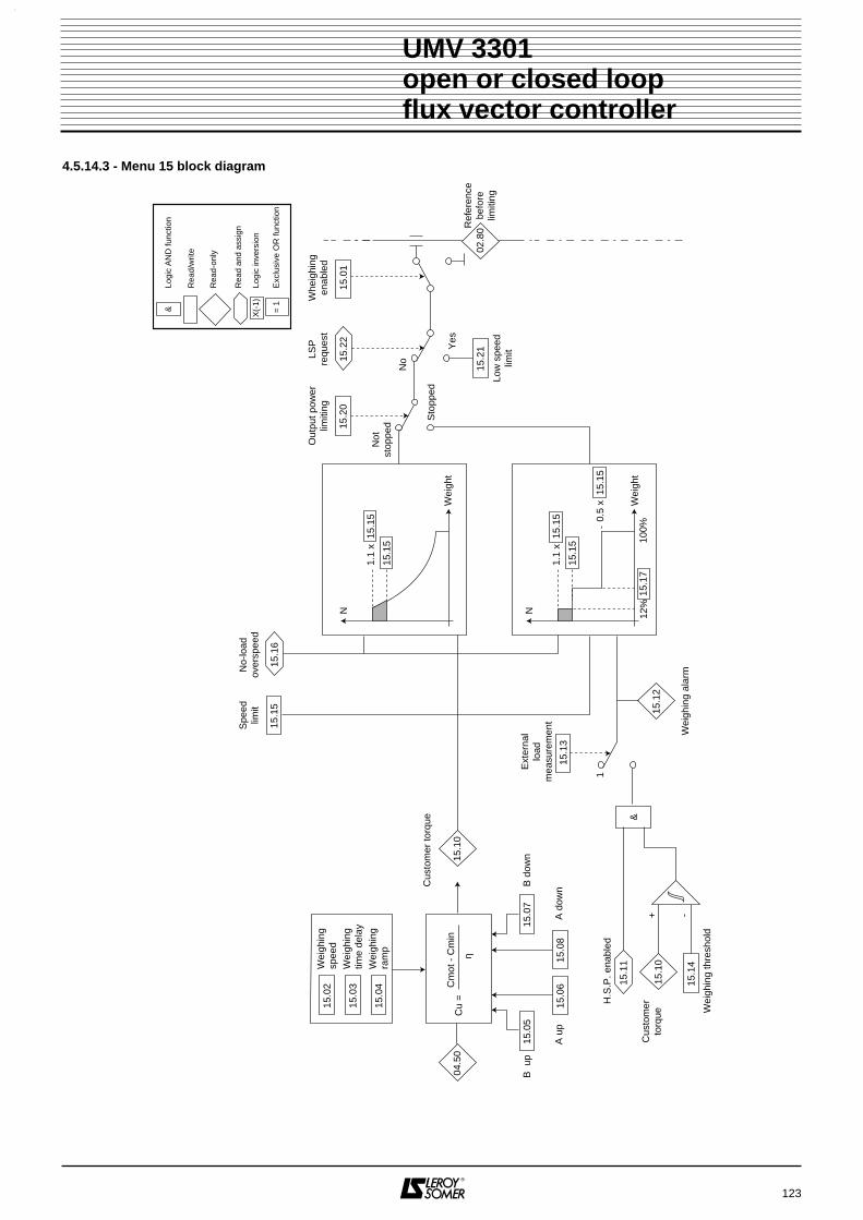
123
UMV 3301 open or closed loopflux vector controller
4.5.14.3 - Menu 15 block diagram
04.5
0
15.1
0
15.1
0
15.1
2
Ext
erna
llo
adm
easu
rem
ent
1
Spe
edlim
itN
o-lo
adov
ersp
eed
Cus
tom
er to
rque
Wei
ghin
g al
arm
15.0
2
15.1
5
15.2
1
Wei
ghin
gsp
eed
B u
pB
dow
n
H.S
.P. e
nabl
ed
Wei
ghin
g th
resh
old
Cus
tom
erto
rque
15.0
3W
eigh
ing
time
dela
y
15.0
4W
eigh
ing
ram
p
15.0
5
15.1
4
15.0
7
15.0
615
.08
15.1
6
Cu
=C
mot
- C
min
η
15.1
3
Out
put p
ower
limiti
ng
Not
stop
ped
Sto
pped
No
Yes
LSP
requ
est
Low
spe
edlim
it
Ref
eren
cebe
fore
limiti
ng
15.2
015
.22
15.1
1&
Whe
ighi
ngen
able
d
15.0
1
A u
pA
dow
n
1.1
x 1
5.15
15.1
5
N
1.1
x 1
5.15
15.1
5
0.5
x 1
5.15
N
Wei
ght
Wei
ght
12%
15.1
710
0%+ -
X(-
1)
= 1
Rea
d/w
rite
Rea
d-on
ly
Rea
d an
d as
sign
Logi
c in
vers
ion
Exc
lusi
ve O
R fu
nctio
n
&Lo
gic
AN
D fu
nctio
n
02.8
0

124
UMV 3301open or closed loopflux vector controller
NOTES

125
UMV 3301 open or closed loopflux vector controller
4.5.15 - Menu 16 : Regen modeThis menu is related to a specific application, and is discribed in the associated instruction. Contact LEROY-SOMER for moreinformation.
CAUTION :Do not modify the setting.
4.5.16 - Menu 17 : Option card 2Under development.
4.5.17 - Menu 19 : Special menuThis menu is related to a specific application, and is discribed in the associated instruction. Contact LEROY-SOMER for moreinformation.
CAUTION :Do not modify the setting.

5 - FAULTS - DIAGNOSTICS
5.1 - General• Information about the controller status is provided bythe display unit.• Faults are indicated by a flashing display.
5.2 - Fault indication
The last ten faults are stored in the memory (even after amains power break) in parameters 11 00 .. 22 00 to 11 00 .. 22 44.• Information about the controller status is also providedby the display unit.• Some controller states can be easily signalled byassigning them to relays or logic outputs.
126
UMV 3301 open or closed loopflux vector controller
DISPLAYASSOCIATEDPARAMETER CHECK POINTS SOLUTION
Bus overvoltage11 00 .. 44 88
- Inertia returned to motor- Optional braking resistor
• Adapt the deceleration• Check the dimensions• Set 00 66 .. 55 77, 00 66 .. 55 88, 00 66 .. 55 99 parameters
Overcurrent
-
- Associated motor
- Parameter settings
• Check the wiring• Motor stalled• Check the limiting in menu 04
I imbalance - - Associated motor • Check the wiring• Check the motor isolation
Controller th.
-
- Cooling
- Overload
• Check the ambient temperature• Check the operation of the controller fans• Clean the ventillation grilles• Check the operating cycle• Check the limitations of menu 04
Resistor th.
-
- Resistor adapted tobraking cycle
- Cooling
• Increase the deceleration time• Check the setting of 00 11 .. 55 88 and 00 11 .. 55 99• Check the ambient temperature• Check the resistor ventilation
Int. power supp
-
- Control terminal block • Check the wiring• Disconnect all the connections and check the +10V, -10V, +24V supplies
Processor
-
- Wiring
- Environment
• Adhere to the wiring precautions for thecontrol terminal block
• Keep the controller away from sources ofinterference
Encoder
-
- Wiring
- Environment
- Motor- Programming
• Check the connection of channels and theencoder supply
• Check the wiring continuity• Check that the encoder cable is free from
interference• Check the mechanical coupling• Check 00 11 .. 33 11
Encoder Loss-
- Wiring • Check the continuity• Check that all channels are present
Processoropt 1 -
- Installation- Adaptation
• Check that the option is correctly installed• Check the programming of menu 16
Processoropt 2 -
- Installation- Adaptation
• Check that the option is correctly installed• Check the programming of menu 17
External00 88 .. 99 00
- Wiring
- Programming
• Check the voltage on the external fault logicinput
• Check the control logicMains failure 11 00 .. 00 55 - Mains supply + protection
- Programming• Check the mains supply voltage• Check the tightness of power connections• Check the mains supply power• Check 11 00 .. 00 66, 11 00 .. 00 77• Check the fuses of EMC cards,
Interface and transformer-trip device
From rating 180T and above.

DISPLAYASSOCIATEDPARAMETER CHECK POINTS SOLUTION
Phase missing
-
- Mains supply + protection • Check the 3 phases, the protective fuses andprotective devices are present
• Check the tightness of power connections• Check the EMC card fuses
Mains under v-
- Mains supply • Check the mains supply voltage• Check the mains supply power
Mains over v -
- Mains supply- Line choke
• Check the mains supply voltage
Bus under v-
- Mains supply • Check the mains supply voltage• Check the connections and the value
Motor th. 11 00 .. 00 99 - Programming • Check the settings for 0011..2211 to 00 11 .. 22 99 and00 11 .. 44 00
Motor PTC probe 11 00 .. 11 00 - Wiring- Environment
• Check the continuity• Check the temperature of the motor and the
ambient temperature• Check the motor ventilation
Direction / Rot 11 00 .. 11 55 - Wiring • Check the order of the 3 motor phases Motor phase 11 00 .. 11 66 - Wiring • Check the motor connections
• Check the motor coilsRS 485 link 11 00 .. 11 11 - Wiring
- Programming• Check the continuity and the conformity• Check 11 33 .. 00 11, 11 33 .. 00 22 and 11 33 .. 00 33
CDC - UMV - - SUB-D console • Check the connection• Check the CD-CORD cable (option)
4/20mA loss 1100..1133 - Wiring
- Programming
• Check the continuity• Check the minimum signal value• Check that the setting of 00 77 .. 33 66 corresponds
to the signal in AI3Alarm 1 active 11 00 .. 44 11 - Environment
- Programming• Check the monitored value • Check 00 55 .. 11 22, 00 55 .. 11 44 and 00 55 .. 11 66
Alarm 2 active 11 00 .. 44 22 - Environment- Programming
• Check the monitored value• Check 0055..2222, 00 55 .. 22 44 and 00 55 .. 22 66
Alarm 3 active 11 00 .. 44 33 - Environment- Programming
• Check the monitored value• Check 00 55 .. 33 22, 00 55 .. 33 44 and 00 55 .. 33 66
Alarm 4 active 11 00 .. 44 44 - Environment- Programming
• Check the monitored value• Check 00 55 .. 44 22, 00 55 .. 44 44 and 00 55 .. 44 66
IGBT - - Power bridge • Check the temperature• Test the bridge
I limit time 11 00 .. 44 00 - Load- Programming
• Check the load and inertia• Check the acceleration ramp• Check 00 55 .. 00 22• Check the limiting in menu 04
Overspeed 00 22 .. 88 33 - 00 22 .. 88 44 - Motor speed
- Speed feedback
• Check the limiting• Driving load• Check the speed feedback• Check the fuses see section 6.4.6
127
UMV 3301 open or closed loopflux vector controller
Note : Certain faults only appear if « Minor fault » or « Major fault » has been selected during processing.A reset can only be carried out once the cause of the fault has disappeared.

6 - MAINTENANCE
6.1 - Introduction and advice
• The power circuit is connected directly to the mains.
• Do not perform any operations on thecontroller without first manually opening the supplycircuit of the power stages (fused isolator or circuit-breaker) or opening the KM input contactor andmanually locking the remote control of KM. Alsoopen the QF circuit-breaker which protects thepower supply to the electronics.
• Wait 10 mins before connecting theprotective covers.
• After performing any operation, replace theprotective covers.UMV 3301 controllers require a minimum ofmaintenance and repair operations on behalf of the user.Detailed below are normal maintenance operations andsimple methods for checking that the controller isoperating correctly.
6.2 - CareAny controller may be subject to problems after beingexposed to excessive heat, humidity, oil, dust, or if anyexternal matter is allowed to penetrate.Printed circuits and their components do not normallyrequire any maintenance. Contact your retailer ornearest approved service centre if any problems occur.
DO NOT REMOVE PRINTED CIRCUIT BOARDSDURING THE GUARANTEE PERIOD, AS THISWILL IMMEDIATELY RENDER IT NULL AND VOID.
Do not touch integrated circuits or the microprocessorwith your fingers or with any charged or live material.Earth yourself, as well as the bench or soldering ironbefore any intervention on the circuits.Do not handle the socket-mounted integrated circuitslocated on the printed control circuit (risk of damage).
Periodically check the tightness of the powerconnections.
6.3 - Measuring voltage, current and power6.3.1 - Mesuring the voltage at the controller outputThe harmonics from the controller mean that it is notpossible to measure the voltage at the motor inputcorrectly with an ordinary voltmeter. However, you canobtain an approximate value of the rms voltage of thefundamental wave (which has a bearing on the torque)by using a standard voltmeter and the arrangement des-cribed in the diagram below.
6.3.2 - Measuring the motor currentThe current drawn by the motor and the controllerinput current can be measured approximately using astandard ammeter.
6.3.3 - Measuring the controller input and outputpowerThe controller input and output power can bemeasured using an electro-dynamic instrument.
128
UMV 3301 open or closed loopflux vector controller
MOTOR 3
U
V
WC : capacitor 0.1µF 400 VAC (1000V peak).R : resistor 1 k , 5W.V : AC voltmeter impedance > 1000 /V.
UMV
3301
C
VR
Ω
Ω

129
UMV 3301open or closed loopflux vector controller
NOTES

6.4 - Spare parts list6.4.1 - UMV 3301 75T to 265T and 75TH to 340TH
UMV 3301 75T to 265T
130
UMV 3301open or closed loopflux vector controller
3
4 1
5
2
UMV 3301 75T to 265T and 75TH to 340TH
L1 L2 L3 PE B- B+ RF PE U V W
6
1
1
2
3
4
5
The dotted line cards are located behind the control card
6
75T to 265T 75TH to 340THFuse item code Fuse item code
Control card - -
Interface card PEL002FA003 None
Transfo triggerF1 Fuse PEL002FA003 PEL002FA003F2 Fuse PEL001FU005 PEL001FU005
EMC card PEL010FU002 PEL010FU002
Bus fuse card PEL002FU004 PEL002FU004
Output voltage measurement PEL002FA003 Nonefuse card
Description Item code UMV 3301 rating75T 100T 120T 150T 180T 220T 265T
Control card PEF240NS000 1 1 1 1 1 1 1Interface card PEF240NP000-2 1
PEF240NP000-3 1PEF240NP000-4 1PEF240NP000-5 1PEF240NB001-1 1PEF240NB001-2 1PEF240NB001-3 1
Transformer trigger device card PEF240NW000 1 1 1 1 1 1 1EMC card PEF240NJ000 1 1 1 1 1 1 1Bus fuse card PEF240NU000 1 1 1 1 1 1 1Voltage measurement fuse card PEF240NK000 3 3 3Rectifier module ESC106MM001 3 3
ESC160MM001 3 3ESC250MM001 3 3ESC430MD001 3ESC330MT001 3
Rectifier + inverter module ESC075EI002 1ESC100EI002 1ESC120EI002 1ESC150EI002 1ESC180EI002 1ESC220EI002 1ESC265EI002 1
Inrush resistor RES047DH001 3 3 3 3RES047PH005 1 1 1
Power supply transformer TRF300CF001 1 1 1 1 1 1 1Varistors PEL550EC000 1 1 1 1 1 1 1Current sensor MES200CA001 2 2
MES300CA001 2 2Fan VEN230VN005 1 1
VEN230VN003 1 1 1 1 1FA 2A 6,3 x 32 - 660V fuse PEL002FU004 2 2 2 2 2 2 2SA 2A 6,3 x 32 - 500V fuse PEL002FA003 1 1 1 1 1 1 1FA 1,25A 6,3 x 32 - 660V fuse PEL001FU005 1 1 1 1 1 1 1FA 10A 6,3 x 32 - 600V fuse PEL010FU002 3 3 3 3 3 3 3
1
2
3
4
6
5
Mounting by an approved LEROY-SOMER facility.: PEL002FA003 : e.g. Ferraz/Shawmut P098131 typePEL010FU002 : e.g. Ferraz/Shawmut B222549 typePEL002FU004 : e.g. Ferraz/Shawmut F093293P typePEL001FU005 : e.g. Ferraz/Shawmut B093289 type or Shurter 70220860 type.

Options
UMV 3301 75TH to 340TH
Options
131
UMV 3301open or closed loopflux vector controller
Mounting by an approved LEROY-SOMER facility.: PEL002FA003 : e.g. Ferraz/Shawmut P098131 type
PEL010FU002 : e.g. Ferraz/Shawmut B222549 typePEL002FU004 : e.g. Ferraz/Shawmut F093293P typePEL001FU005 : e.g. Ferraz/Shawmut B093289 type or Shurter 70220860 type.
Description Item code TUMV 100 TUMV 210 TUMV 220Braking transistor ESC145QI000 1
ESC300QI000 1 1Braking card PEF240NC001 1
PEF240NC002 1 1
Description Item code UMV 3301 rating75TH 100TH 120TH 150TH 180TH 220TH 265TH 340TH
Control card PEF240NS100 1 1 1 1 1 1 1 1Interface card PEF240NB101-1 1
PEF240NB101-2 1PEF240NB101-3 1PEF240NB101-4 1PEF240NB101-5 1PEF240NB101-6 1PEF240NB101-C 1PEF240NB101-7 1
Transformer trigger device card PEF240NW100 1 1 1 1 1 1 1 1EMC card PEF240NJ100 1 1 1 1 1 1 1 1Bus fuse card PEF240NU100 1 1 1 1 1 1 1 1Voltage measurement fuse card PEF240NK100 3 3 3 3 3 3 3 3Rectifier module SKKH57/22E 3
SKKH72/22E 3SKKH132/22 3 3SKKH131/22 3 3SKKH210/22 3 3
Rectifier + inverter module ESC075EI100 1ESC100EI100 1ESC120EI100 1ESC150EI100 1ESC180EI100 1 1ESC265EI100 1ESC340EI100 1
Inrush resistor RES180PH002 1 1 1 1RES047DH005 1 1 1 1
Power supply transformer TRF300CF001 1 1 1 1 1 1 1 1Varistors PEL750EC001 1 1 1 1 1 1 1 1Current sensor MES200CA001 2 2
MES300CA001 2 2Fan VEN230VN003 1 1 1 1 1 1 1 1FA 2A 6,3 x 32 - 660V fuse PEL002FU004 2 2 2 2 2 2 2 2SA 2A 6,3 x 32 - 500V fuse PEL002FA003 1 1 1 1 1 1 1 1FA 1,25A 6,3 x 32 - 660V fuse PEL001FU005 1 1 1 1 1 1 1 1FA 10A 6,3 x 32 - 600V fuse PEL010FU002 3 3 3 3 3 3 3 3
1
2
3
4
6
5
Description Item code TUMV TH 85 TUMV TH 175Braking transistor ESC200QI000 1
ESC380QI000 1Braking card PEF240NC101 1
PEF240NC102 1

6.4.2 - UMV 3301 270T to 600T and 400TH to 700TH
UMV 3301 270T to 600T
132
UMV 3301open or closed loopflux vector controller
Description Item code UMV 3301 rating
270T 340T 400T 470T 600T
Control card PEF240NS000 1 1 1 1 1
Interface card PEF240NB001 1 1 1 1 1
Transformer trigger device card PEF240NW000 1 1 1 1 1
EMC card PEF240NL000 1 1 1 1 1
Bus fuse card PEF240NK000 2 2 4 4 4
Output voltage measurement fuse card PEF240NK000 3 3 3 3 3
Input voltage measurement fuse card PEF240NK000 3 3 3 3 3
OCP2 power supply card PEF249NA000 - - 1 1 1
FV inverter rectifier module ESC270EI002 3
ESC340EI002 3
ESC400EI002 3
ESC470EI002 3
ESC600EI002 3
Forced ventilation VEN230VM006 3
VEN230VM007 3 3 3 3
Inrush resistance RES018PH001
FU 6.3 x 32 2A SA fuse on and PEL002FA003 5 5 5 5 5
FU 6.3 x 32 2A fuse on PEL002FU004 2 2 4 4 4
FA 6.3 x 32 8A fuse on PEL008FA004 3 3 3 3 3
10 x 38 AM 4A fuse PEL004FG000 10 10 10 10 108
9
7
1
2
3
4
6
5
36
7 7
5
8
1
96
24
1 Control card
Interface card
Transfo trigger device card (fuses : PEL002FA003)
EMC card
2
3
4
Bus fuse card (fuses : PEL002FU004)5
Output voltage measurement fuse card (fuses : PEL002FA003)6
Input voltage measurement fuse card (fuses : PEL008FA004)7
Transformer protection (fuses : PEL004FG000)
OCP2 power supply card (UMV ≥ 400T)
8
9
7
3 6
5
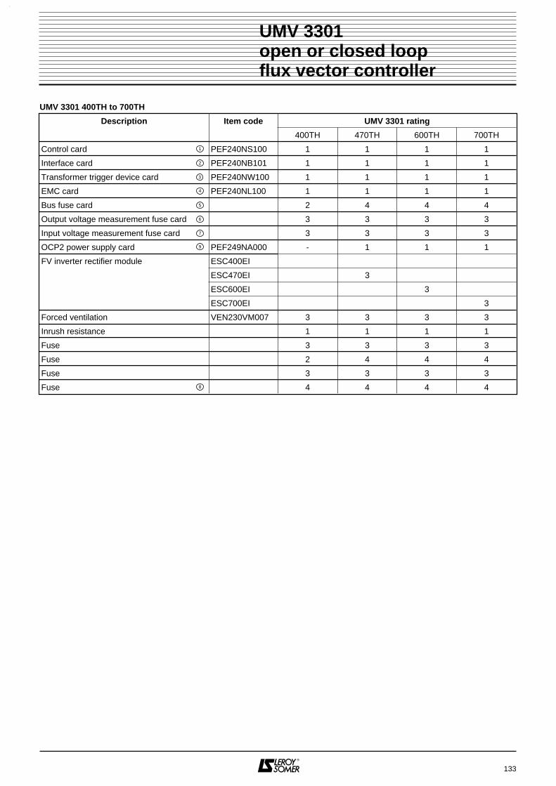
UMV 3301 400TH to 700TH
133
UMV 3301open or closed loopflux vector controller
Description Item code UMV 3301 rating
400TH 470TH 600TH 700TH
Control card PEF240NS100 1 1 1 1
Interface card PEF240NB101 1 1 1 1
Transformer trigger device card PEF240NW100 1 1 1 1
EMC card PEF240NL100 1 1 1 1
Bus fuse card 2 4 4 4
Output voltage measurement fuse card 3 3 3 3
Input voltage measurement fuse card 3 3 3 3
OCP2 power supply card PEF249NA000 - 1 1 1
FV inverter rectifier module ESC400EI
ESC470EI 3
ESC600EI 3
ESC700EI 3
Forced ventilation VEN230VM007 3 3 3 3
Inrush resistance 1 1 1 1
Fuse 3 3 3 3
Fuse 2 4 4 4
Fuse 3 3 3 3
Fuse 4 4 4 48
9
7
1
2
3
4
6
5

6.4.3 - Control cardMain component installation
134
UMV 3301 open or closed loopflux vector controller
AA +5V
CO
D0V
CO
DB B O O
P11P3
S1
S3
P4
P8P2
P14
U6
CR2
AI1
++
10V
-10V
AI1
-A
I2A
I3T
HE
RM
0V AO
1A
O2
0V
P16
DI1
+24
V
DI2
DI3
DI4
DI5
0V DO
1D
O2
DO
3
P13
EX
T-F
LT+
24V
RE
SE
T0V 0V F
WD
RE
VE
NA
BLE
+24
V
P15R
L12
RL1
1
RL2
1R
L22
RL3
1R
L32
P12
1
ONOFF2
P6
P7
K1 K2 K3
1
1
1
P1
CR4CR3 CR5
Controllogic
0V
P9
E5
P17
P18
U63
U61
Y1
S2
U60
U48ODD EVEN
U62
P10
0V
S1
1
ON: the terminating resistor is rated for 4 wire connectionOFF2
S1
1
ON: the terminating resistor is rated for 2 wire connectionOFF2
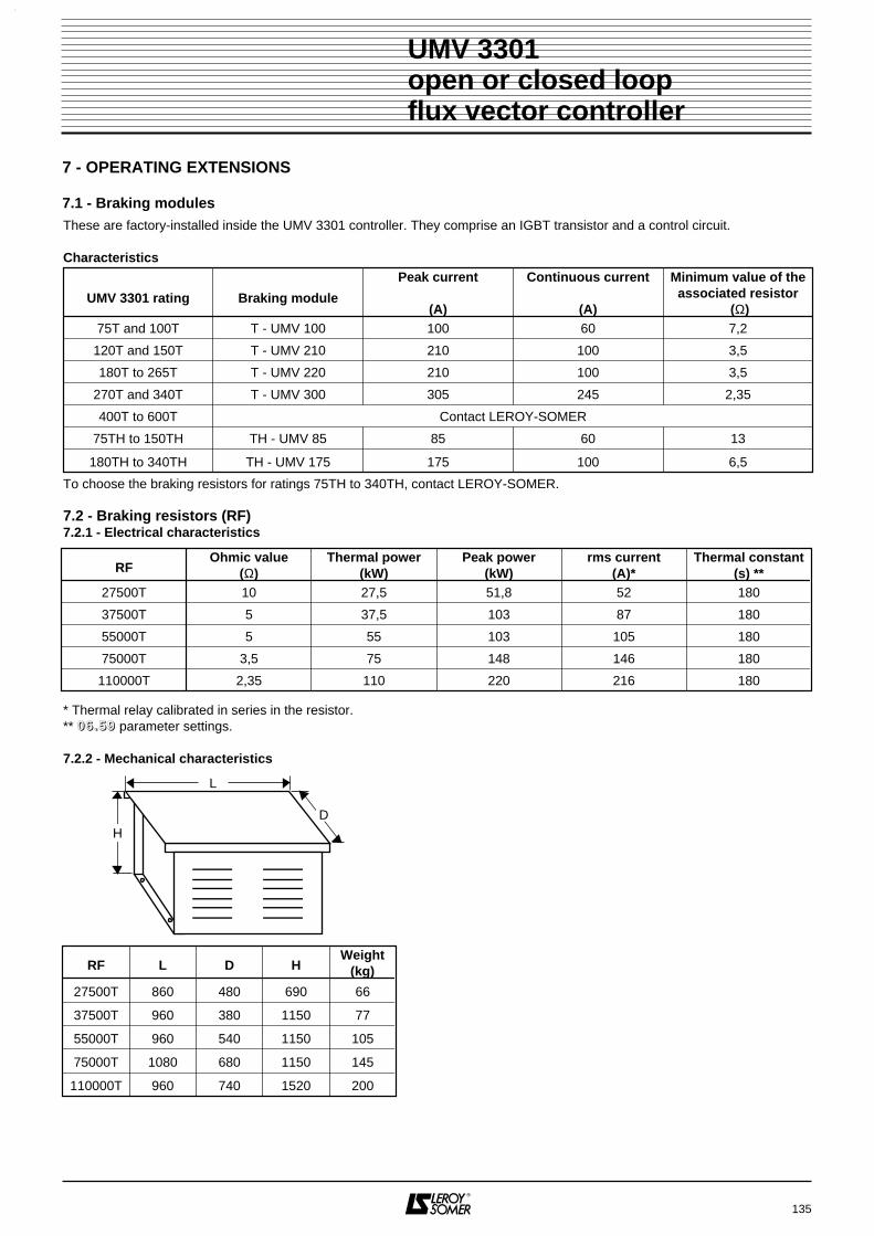
7 - OPERATING EXTENSIONS
7.1 - Braking modules
135
UMV 3301 open or closed loopflux vector controller
These are factory-installed inside the UMV 3301 controller. They comprise an IGBT transistor and a control circuit.
Characteristics
To choose the braking resistors for ratings 75TH to 340TH, contact LEROY-SOMER.
7.2 - Braking resistors (RF)7.2.1 - Electrical characteristics
* Thermal relay calibrated in series in the resistor.** 00 66 .. 55 99 parameter settings.
7.2.2 - Mechanical characteristics
HD
L
RF L D HWeight
(kg)
27500T 860 480 690 66
37500T 960 380 1150 77
55000T 960 540 1150 105
75000T 1080 680 1150 145
110000T 960 740 1520 200
UMV 3301 rating Braking module
Peak current
(A)
Continuous current
(A)
Minimum value of theassociated resistor
(Ω)75T and 100T T - UMV 100 100 60 7,2
120T and 150T T - UMV 210 210 100 3,5
180T to 265T T - UMV 220 210 100 3,5
270T and 340T T - UMV 300 305 245 2,35
400T to 600T Contact LEROY-SOMER
75TH to 150TH TH - UMV 85 85 60 13
180TH to 340TH TH - UMV 175 175 100 6,5
RFOhmic value
(Ω)Thermal power
(kW)Peak power
(kW)rms current
(A)*Thermal constant
(s) **27500T 10 27,5 51,8 52 180
37500T 5 37,5 103 87 180
55000T 5 55 103 105 180
75000T 3,5 75 148 146 180
110000T 2,35 110 220 216 180

7.3 - RFI filters7.3.1 - Electrical characteristics
* 500Vac - 50Hz mains supply
7.3.2 - Characteristics• FLT 3359 HV - 180 and FLT 3359 HV - 250
• FLT 3359 HV - 320 to FLT 3359 HV - 1600
136
UMV 3301 open or closed loopflux vector controller
Type Nominal current (A) Leakage current (mA) * Losses (W)FLT 3359 HV - 180 180 < 6 38FLT 3359 HV - 250 250 < 6 57FLT 3359 HV - 320 320 < 6 40FLT 3359 HV - 400 400 < 6 50FLT 3359 HV - 600 600 < 6 65FLT 3359 HV - 1000 1000 < 6 91FLT 3359 HV - 1600 1600 < 6 180
Type Dimensions (mm) Weight (kg)L L1 H H1 P Ø1
FLT 3359 HV - 180 - 120 210 185 120 12 6.5FLT 3359 HV - 250 - 120 230 205 125 12 7FLT 3359 HV - 320 386 120 260 235 115 12 10.5FLT 3359 HV - 400 386 120 260 235 115 12 10.5FLT 3359 HV - 600 386 120 260 235 135 12 11FLT 3359 HV - 1000 456 145 280 255 170 12 18FLT 3359 HV - 1600 586 170 300 275 160 12 27
L
L1 L1
HH1
Ø1
M
P
L P
L1 L1
HH1
Ø1
M

ConnectionEarth connection is by means of an M12 screw ; inputand output connections are on the terminals (dimensionsaccording to rating - see table below).
All dimensions in mm.
7.4 - Self-MC chokesThese are wired directly to the controller output (U, V, Wterminals) and help reduce leakage currents and interfe-rence.
• WiringSelf-MC chokes must be wired as close as possible tothe inverter.
• Dimensions
7.5 - Forced ventilation kitThe UMV 3301 180T and 220T can accommodate a kitwhich enables fresh air from outside the cubicle to becirculated inside.
7.6 - Connection optionThe UMV 3301 270T to 600T can accommodate anoption comprising an isolator, a power contactor and theRFI filter option for supplying the UMV.This takes the form of a cubicle section of 600 mm whichfixes against the UMV 3301 cubicle.
7.7 - PEGASE parameter-setting softwareThis software enables the serial link and an RS 232/RS 485interface to access all UMV 3301 inverter parameters via aPC.The software is particularly suitable for repetitive controllerprogramming.
137
UMV 3301open or closed loopflux vector controller
D d
e
Dimensions Type of FLT 3359 HV Tol.
320 & 400 600 1000 1600 mm
A 25 25 40 60 ±0.1
B 6 8 8 10 ±0.1
C 15 15 20 17 ±0.5
D 40 40 50 90 ±1.5
E 10,5 10,5 14 14 ±0.2
F - - - 26 ±0.2
G - - - 26 ±0.2
BE
A
C
D
BE
G A
DCF
FLT 3359 HV - 320to
FLT 3359 HV - 1000FLT 3359 HV - 1600
Dimensions (mm)
D d e
FAP038FE001 63 38 25
FAP055FE001 100 55 20

138
UMV 3301open or closed loopflux vector controller
NOTES
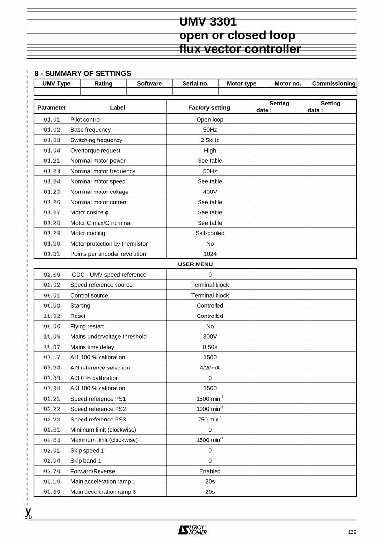
8 - SUMMARY OF SETTINGS
139
UMV 3301 open or closed loopflux vector controller
UMV Type Rating Software Serial no. Motor type Motor no. Commissioning
Parameter Label Factory setting Setting
date : Setting
date :
00 11 .. 00 11 Pilot control Open loop
00 11 .. 00 22 Base frequency 50Hz
00 11 .. 00 33 Switching frequency 2.5kHz
00 11 .. 00 44 Overtorque request High
00 11 .. 22 11 Nominal motor power See table
00 11 .. 22 33 Nominal motor frequency 50Hz
00 11 .. 22 44 Nominal motor speed See table
00 11 .. 22 55 Nominal motor voltage 400V
00 11 .. 22 66 Nominal motor current See table
00 11 .. 22 77 Motor cosine ϕ See table
00 11 .. 22 88 Motor C max/C nominal See table
00 11 .. 22 99 Motor cooling Self-cooled
00 11 .. 33 00 Motor protection by thermistor No
00 11 .. 33 11 Points per encoder revolution 1024
00 22 .. 55 00 CDC - UMV speed reference 0
00 22 .. 00 22 Speed reference source Terminal block
00 66 .. 00 11 Control source Terminal block
00 66 .. 00 33 Starting Controlled
11 00 .. 00 22 Reset Controlled
00 66 .. 00 55 Flying restart No
11 00 .. 00 66 Mains undervoltage threshold 300V
11 00 .. 00 77 Mains time delay 0.50s
00 77 .. 11 77 AI1 100 % calibration 1500
00 77 .. 33 66 AI3 reference selection 4/20mA
00 77 .. 33 33 AI3 0 % calibration 0
00 77 .. 33 44 AI3 100 % calibration 1500
00 22 .. 22 11 Speed reference PS1 1500 min-1
00 22 .. 22 22 Speed reference PS2 1000 min-1
00 22 .. 22 33 Speed reference PS3 750 min-1
00 22 .. 88 11 Minimum limit (clockwise) 0
00 22 .. 88 33 Maximum limit (clockwise) 1500 min-1
00 22 .. 99 11 Skip speed 1 0
00 22 .. 99 44 Skip band 1 0
00 22 .. 77 00 Forward/Reverse Enabled
00 33 .. 11 00 Main acceleration ramp 1 20s
00 33 .. 33 00 Main deceleration ramp 3 20s
USER MENU

140
UMV 3301 open or closed loopflux vector controller
Parameter Label Factory setting Setting
date : Setting
date :
00 77 .. 22 99 AI2 destination None
00 77 .. 22 77 AI2 100 % calibration 100
00 44 .. 33 66 Motor torque limit 2 110 % Mn
00 55 .. 11 22 Alarm 1 threshold 0
00 55 .. 22 22 Alarm 2 threshold 1500
00 77 .. 55 22 AO1 type selection 4/20mA
00 77 .. 55 77 AO1 100 % calibration 150
00 77 .. 66 22 AO2 type selection 4/20mA
00 77 .. 66 77 AO2 100 % calibration 1800
00 44 .. 00 44 Stability 4.0
00 22 .. 00 22 Speed reference source Terminal block
00 22 .. 00 33 RS 485 reference enabled No
00 22 .. 11 33 Additional speed reference 0
00 22 .. 11 44 No. 1 - No. 2 selection Speed ref. no. 1
00 22 .. 11 55 Summing selection No
00 22 .. 22 11 PS1 reference 1500 min-1
00 22 .. 22 22 PS2 reference 1000 min-1
00 22 .. 22 33 PS3 reference 750 min-1
00 22 .. 22 44 PS4 reference 3000 min-1
00 22 .. 22 55 PS5 reference 900 min-1
00 22 .. 22 66 PS6 reference 1200 min-1
00 22 .. 22 77 PS7 reference 1800 min-1
00 22 .. 33 33 Motorized potentiometer function Disabled
00 22 .. 33 44 Motorized potentiometer sensitivity 100 s-1
00 22 .. 33 55Motorized potentiometermemorisation No
00 22 .. 44 00 Jogging reference 150 min-1
00 22 .. 44 44Locking of joggingzero reference No
00 22 .. 55 00 CDC-UMV speed reference 0
00 22 .. 77 00 Forward/Reverse Enabled
00 22 .. 88 11 Minimum limit clockwise 0
00 22 .. 88 22 Minimum limit anti-clockwise 0
00 22 .. 88 33 Maximum limit clockwise 1500 min-1
00 22 .. 88 44 Maximum limit anti-clockwise 1500 min-1
00 22 .. 88 55 Symmetry selection Yes
00 22 .. 99 11 Skip speed 1 0
00 22 .. 99 22 Skip speed 2 0
00 22 .. 99 33 Skip speed 3 0
00 22 .. 99 44 Skip band 1 0
00 22 .. 99 55 Skip band 2 0
00 22 .. 99 66 Skip band 3 0

141
UMV 3301 open or closed loopflux vector controller
Parameter Label Factory setting Setting
date : Setting
date :
00 33 .. 00 33 Additional reference without ramp 0
00 33 .. 00 44 Starting speed 0
00 33 .. 00 55 Special ramp selection No
00 33 .. 00 66 Special ramp rounding 10
00 33 .. 00 77 Ramp Unlocked
00 33 .. 00 88 Ramp by-pass No
00 33 .. 00 99 Main ramp mode 1
00 33 .. 11 00 Main ramp 1 20.0s
00 33 .. 11 11 Main ramp 2 20.0s
00 33 .. 11 22 Speed threshold on acceleration 8000 min-1
00 33 .. 11 55Acceleration/decelerationassociated programming Yes
00 33 .. 11 66Associated programmable speedsand ramps Yes
00 33 .. 22 11 Acceleration ramp 1/5 20.0s
00 33 .. 22 22 Acceleration ramp 2/6 20.0s
00 33 .. 22 33 Acceleration ramp 3/7 20.0s
00 33 .. 22 88 Jogging acceleration ramp 10.0s
00 33 .. 33 00 Main ramp no. 3 20.0s
00 33 .. 33 11 Main ramp no. 4 20.0s
00 33 .. 33 22 Speed threshold on deceleration 0
00 33 .. 44 11 Deceleration ramps 1/5 20.0s
00 33 .. 44 22 Deceleration ramps 2/6 20.0s
00 33 .. 44 33 Deceleration ramps 3/7 20.0s
00 33 .. 44 88 Jogging deceleration ramp 10.0s
00 33 .. 55 00 Special ramp type S type
00 44 .. 00 33 Dynamic performance 1.0
00 44 .. 00 44 Stability 4.0
00 44 .. 00 55 Torque d/dt 10.00 %/ms
00 44 .. 11 00 Torque reference 0
00 44 .. 11 11 Control type Speed
00 44 .. 11 22 Zero torque selection No
00 44 .. 11 33 Torque offset 0
00 44 .. 11 44 Torque offset selection 0
00 44 .. 33 33 Limit 1 or limit 2 enable Limit 2
00 44 .. 33 44 Torque limit 1 in motor mode 150 % Mn
00 44 .. 33 55 Time delay limit 1 --> 2 60 s
00 44 .. 33 66 Torque limit 2 in motor mode 110 % Mn
00 44 .. 33 77 Torque limit in generator mode 120 % Mn
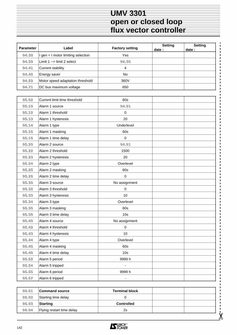
142
UMV 3301 open or closed loopflux vector controller
Parameter Label Factory setting Setting
date : Setting
date :
00 44 .. 33 88 I gen = I motor limiting selection Yes
00 44 .. 33 99 Limit 1 --> limit 2 select 00 44 .. 33 55
00 44 .. 44 11 Current stability 4
00 44 .. 44 66 Energy saver No
00 44 .. 66 99 Motor speed adaptation threshold 360V
00 44 .. 77 11 DC bus maximum voltage 650
00 55 .. 00 22 Current limit time threshold 60s
00 55 .. 11 00 Alarm 1 source 00 44 .. 00 11
00 55 .. 11 22 Alarm 1 threshold 0
00 55 .. 11 33 Alarm 1 hysteresis 20
00 55 .. 11 44 Alarm 1 type Underlevel
00 55 .. 11 55 Alarm 1 masking 60s
00 55 .. 11 66 Alarm 1 time delay 0
00 55 .. 22 00 Alarm 2 source 00 44 .. 00 11
00 55 .. 22 22 Alarm 2 threshold 1500
00 55 .. 22 33 Alarm 2 hysteresis 20
00 55 .. 22 44 Alarm 2 type Overlevel
00 55 .. 22 55 Alarm 2 masking 60s
00 55 .. 22 66 Alarm 2 time delay 0
00 55 .. 33 00 Alarm 3 source No assignment
00 55 .. 33 22 Alarm 3 threshold 0
00 55 .. 33 33 Alarm 3 hysteresis 10
00 55 .. 33 44 Alarm 3 type Overlevel
00 55 .. 33 55 Alarm 3 masking 60s
00 55 .. 33 66 Alarm 3 time delay 10s
00 55 .. 44 00 Alarm 4 source No assignment
00 55 .. 44 22 Alarm 4 threshold 0
00 55 .. 44 33 Alarm 4 hysteresis 10
00 55 .. 44 44 Alarm 4 type Overlevel
00 55 .. 44 55 Alarm 4 masking 60s
00 55 .. 44 66 Alarm 4 time delay 10s
00 55 .. 55 22 Alarm 5 period 9999 h
00 55 .. 55 44 Alarm 5 tripped -
00 55 .. 55 55 Alarm 6 period 9999 h
00 55 .. 55 77 Alarm 6 tripped -
00 66 .. 00 11 Command source Terminal block
00 66 .. 00 22 Starting time delay 0
00 66 .. 00 33 Starting Controlled
00 66 .. 00 44 Flying restart time delay 2s

143
UMV 3301 open or closed loopflux vector controller
Parameter Label Factory setting Setting
date : Setting
date :
00 66 .. 00 55 Flying restart No
00 66 .. 00 66 Zero reference locked No
00 66 .. 00 77 Semi manual starting No
00 66 .. 11 00 Boost type Fixed
00 66 .. 11 11 Boost level 0
00 66 .. 11 22 Type of ratio Fixed
00 66 .. 44 00 Starting overtorque 0
00 66 .. 44 11 Flux time delay 250 ms
00 66 .. 44 22 Flux at stop No
00 66 .. 44 33 Flux stop time delay 10s
00 66 .. 44 44 Locked rotor function Fix torque
00 66 .. 55 00 Brake present No
00 66 .. 55 11Minimum current on brakeengagement 0
00 66 .. 55 22 Brake release speed 0
00 66 .. 55 33 Brake engagement time 0.1s
00 66 .. 55 44 Brake release time 0.1s
00 66 .. 55 77 Braking resistor present No
00 66 .. 55 88 Braking power (S1) 0
00 66 .. 55 99 Resistance time constant 180s
00 66 .. 66 22 Stopping mode On ramp
00 66 .. 66 33 Stopping mode 1 (priority) Freewheel
00 66 .. 66 44 Stopping mode for minor faults On ramp
00 66 .. 77 11 Timed low speed setting 150 min-1
00 66 .. 77 22 Low speed operation duration 5.0 s
00 66 .. 77 33 Speed for start of DC injection 150 min-1
00 66 .. 77 44 Injection level 100 % In
00 66 .. 77 55 Duration of injection 5 s
00 77 .. 11 11 AI1 offset 0
00 77 .. 11 22 AI1 offset selection No
00 77 .. 11 33 AI1 minimum calibration 0
00 77 .. 11 44 AI1 maximum calibration 100.00 %
00 77 .. 11 55 AI1 input polarity 2-pole
00 77 .. 11 77 AI1 100 % calibration 1500
00 77 .. 11 99 AI1 destination Speed no.1
00 77 .. 22 11 AI2 offset 0
00 77 .. 22 22 AI2 offset selection No
00 77 .. 22 33 AI2 minimum calibration 0
00 77 .. 22 44 AI2 maximum calibration 100.0 %
00 77 .. 22 55 AI2 input polarity 2-pole

144
UMV 3301 open or closed loopflux vector controller
Parameter Label Factory setting Setting
date : Setting
date :
00 77 .. 22 77 AI2 100 % calibration 100
00 77 .. 22 99 AI2 destination None
00 77 .. 33 33 AI3 0 % calibration 0
00 77 .. 33 44 AI3 100 % calibration 1500
00 77 .. 33 55 AI3 input inversion No
00 77 .. 33 66 AI3 reference selection 4/20 mA
00 77 .. 33 99 AI3 destination Speed no. 2
00 77 .. 55 11 AO1 signal conversion No
00 77 .. 55 22 AO1 type selection 4 - 20 mA
00 77 .. 55 33 AO1 output filter 2
00 77 .. 55 77 AO1 100 % calibration 150
00 77 .. 55 99 AO1 signal source Total motor current
00 77 .. 66 11 AO2 signal conversion No
00 77 .. 66 22 AO2 type selection 4 - 20 mA
00 77 .. 66 33 AO2 output filter 2
00 77 .. 66 77 AO2 100 % calibration 1800
00 77 .. 66 99 AO2 signal source Motor speed
00 88 .. 11 11 DI1 destination Select 1PS
00 88 .. 11 22 DI1 input inversion No
00 88 .. 22 11 DI2 destination Select 3PS
00 88 .. 22 22 DI2 input inversion No
00 88 .. 33 11 DI3 destination Stop 1
00 88 .. 33 22 DI3 input inversion No
00 88 .. 44 11 DI4 destination Select ref. N1-N2
00 88 .. 44 22 DI4 input inversion No
00 88 .. 55 11 DI5 logic destination Ramp locking
00 88 .. 55 22 DI5 input inversion No
00 88 .. 66 11 REV input destination Reverse/Stop
00 88 .. 66 22 REV input inversion No
00 99 .. 11 11 RL1 source 1 Alarm 1 state
00 99 .. 11 22 RL1 source 1 inverted No
00 99 .. 11 33 RL1 source 2 No assignment
00 99 .. 11 44 RL1 source 2 inverted No
00 99 .. 11 55 RL1 relay inverted Yes
00 99 .. 11 66 RL1 relay time delay 2 s
00 99 .. 11 77 RL1 relay selection Single source
00 99 .. 22 11 RL2 source 1 UMV 3301 output
00 99 .. 22 22 RL2 source 1 inverted No

145
UMV 3301 open or closed loopflux vector controller
Parameter Label Factory setting Setting
date : Setting
date :
00 99 .. 22 33 RL2 source 2 No assignment
00 99 .. 22 44 RL2 source 2 inverted No
00 99 .. 22 55 RL2 relay inverted No
00 99 .. 22 66 RL2 relay time delay 2.0 s
00 99 .. 22 77 RL2 relay selection Single source
00 99 .. 33 11 DO1 source I limit reached
00 99 .. 33 22 DO1 source inverted No
00 99 .. 33 66 DO1 output time delay 2.0 s
00 99 .. 44 11 DO2 source UMV fault
00 99 .. 44 22 DO2 source inverted Yes
00 99 .. 44 66 DO2 output time delay 2.0 s
00 99 .. 55 11 DO3 logic information source Alarm 2 state
00 99 .. 55 22 DO3 source inversion No
00 99 .. 55 44 DO3 scaling 0.033
00 99 .. 55 66 DO3 output time delay 2.0 s
00 99 .. 55 77 DO3 output mode Logic output
11 00 .. 00 11 Reset originTerminal block + CDC-UM
+ RS 485
11 00 .. 00 22 Reset mode Controlled
11 00 .. 00 33 Number of authorised resets 3
11 00 .. 00 44 Automatic reset time delay 10.0 s
11 00 .. 00 55 Mains fault Major fault
11 00 .. 00 66 Mains undervoltage threshold 300V
11 00 .. 00 77 Mains fault time delay 0.50 s
11 00 .. 00 99 Motor thermal fault Minor fault
11 00 .. 11 00 Motor PTC fault Minor fault
11 00 .. 11 11 RS 485 serial link fault Minor fault
11 00 .. 11 22 CDC - UMV fault Disabled
11 00 .. 11 33 4 - 20mA break processing Disabled
11 00 .. 11 55 Monitoring direction of rotation Disabled
11 00 .. 11 66 Motor phase break Disabled
11 00 .. 22 00 Current limit time Disabled
11 00 .. 22 11 Alarm 1 destination Disabled
11 00 .. 22 22 Alarm 2 destination Disabled
11 00 .. 22 33 Alarm 3 destination Disabled
11 00 .. 22 44 Alarm 4 destination Disabled

146
UMV 3301 open or closed loopflux vector controller
Parameter Label Factory setting Setting
date : Setting
date :
11 22 .. 11 11 Threshold No. 1 source 00 44 .. 00 11
11 22 .. 11 22 Threshold No. 1 level 9999
11 22 .. 11 33 Threshold No. 1 hysteresis 2
11 22 .. 11 44 Threshold No. 1 inversion No
11 22 .. 11 55 Threshold No. 1 destination None
11 22 .. 22 11 Threshold No. 2 source 00 44 .. 00 11
11 22 .. 22 22 Threshold No. 2 level 9999
11 22 .. 22 33 Threshold No. 2 hysteresis 2
11 22 .. 22 44 Threshold No. 2 inversion No
11 22 .. 22 55 Threshold No. 2 destination None
11 33 .. 00 11 Serial link address 11
11 33 .. 00 22 Speed 9600 bauds
11 33 .. 00 33 Parity Odd
11 33 .. 00 44 Serial link monitoring No
11 33 .. 00 55 Monitoring period 10
11 33 .. 00 66 Serial link self-test No
11 33 .. 00 88 Parameter-setting mode CDC-UMV
11 33 .. 11 00 MODBUS control MODBUS
11 33 .. 11 11 Inhibit MODBUS control No
11 44 .. 22 11 Programmable PID reference 1 0
11 44 .. 22 22 Programmable PID reference 2 0
11 44 .. 22 33 Programmable PID reference 3 0
11 44 .. 22 55 PID ramp 600.0
11 44 .. 33 11 PID feedback inversion No
11 44 .. 33 22 PID feedback source -
11 44 .. 44 11 PID proportional gain 10
11 44 .. 44 22 PID integral gain 10
11 44 .. 44 33 PID derivative gain 0
11 44 .. 44 44 PID low limit 0
11 44 .. 44 55 PID high limit +8000
11 44 .. 44 66 PID integral locked No
11 44 .. 44 77 Scaling of PID output 1.00
11 44 .. 44 88 PID output summing No
11 44 .. 44 99 PID additionnal reference 0
11 44 .. 55 00 PID enabled No
11 44 .. 55 11 Programmable condition Always enabled
11 44 .. 55 22 Programmable condition inversion No
11 44 .. 66 00 PID destination None

147
UMV 3301 open or closed loopflux vector controller
Parameter Label Factory setting Setting
date : Setting
date :
11 55 .. 00 11 Weighing enabled No
11 55 .. 00 22 Weighing speed 1500 min-1
11 55 .. 00 33 Weighing time delay 0.4s
11 55 .. 00 44 Weighing ramp 20s
11 55 .. 00 55 B up 0
11 55 .. 00 66 A up 100
11 55 .. 00 77 B down 0
11 55 .. 00 88 A down 100
11 55 .. 11 33 External load measurement No
11 55 .. 11 44 Weighing threshold 50 % Mn
11 55 .. 11 55 Speed limit 3000 min-1
11 55 .. 11 77 Stepper limitation threshold 33 % Mn
11 55 .. 22 00 Limiting selection With step
11 55 .. 22 11 Low speed limiting 50 min-1

UMV 3301 open or closed loopflux vector controller
NOTES

UMV 3301 open or closed loopflux vector controller
NOTES

UMV 3301 open or closed loopflux vector controller
NOTES


MOTEURS LEROY-SOMER 16015 ANGOULÊME CEDEX - FRANCE
RCS ANGOULÊME N° B 671 820 223S.A. au capital de 131 910 700 F
http://www.leroy-somer.com

DOSSIER TECHNIQUE
GESTION D'EVOLUTION DE LA NOTICEUMV 3301
Installation and maintenanceréf. 2416 GB - 4.33
Classement : 3301
Révision : Bdu : 26/01/01
Page : 1/3
DOCUMENT type : T412 T010
Chap. : 5DEPARTEMENT
DEI
QUALITE
Version Nature de l'évolution Paragraphes concernés
b - 6.98 Notice de basec - 6.00 • Modification of software version
• Modification of filter references• Modification of drive power and speed range• Addition of " TH " ratings• Addition of electrical characteristics for UMV
265T and all " TH " ratings• Modification of the characteristic table for " T "
ratings• Addition of smoothing choke characteristics for
ratings " TH "• Addition of fast stopping mode details and
suppression of jogging in indexed stopping mode• Suppression of one dedicated input• Addition of TH-UMV and T-UMV 220 modules• Modification of vibration standard ans shock peak
acceleration• Addition of ingress protection for UMV 3301 265T
and " TH " ratings• Addition of losses and forced ventilation flow for
UMV 265T and " TH " ratings• Modification of losses for 180T and 220T,
modification of forced ventilation flow for 120T and 150T
• Addition of weight and dimensions for 265T and all " TH " ratings
• Modification of dimensions for 180T and 220T• Suppression of smoothing choke details• Modification on the table for the drive handling
(modification of 180T, 220T and addition of 265T and all " TH " ratings)
• Modification of dimensions for fixing 180T & 220T• Addition of dimensions for fixing 265T and all
" TH " ratings• Modification of the access to the terminal blocks• Modification of the power terminal blocks• Modification of the control terminal blocks• Modification of the factory setting for DO3• Addition of a drawing and modification of the
voltage range for supplying drives by DC bus• Modification of the RFI filters and addition of the
" TH " ratings• Addition of a warning about the use of RFI filters
on a IT power supply
Page 2Preface
1.11.2
1.3.1 & 1.3.2
1.3.1 & 1.3.2
1.3.3
1.3.4
1.3.41.3
1.4.1
1.4.1
1.4.2
1.4.2
1.5.1
1.5.11.5.2, 2.1 & 2.5
2.2
2.42.4
3.2.1.13.2.23.2.3
3.2.4.23.2.5.3
3.3.6.2
3.3.6.2

DOSSIER TECHNIQUE
GESTION D'EVOLUTION DE LA NOTICEUMV 3301
Installation and maintenanceréf. 2416 GB - 4.33
Classement : 3301
Révision : Bdu : 26/01/01
Page : 2/3
DOCUMENT type : T412 T010
Chap. : 5DEPARTEMENT
DEI
QUALITE
Version Nature de l'évolution Paragraphes concernés
c - 6.00(suite)
• Addition of a table for " TH " rating fuses and cables and modification of the table for " T " ratings
• Addition of the recommended fuses and cables for 265T
• Suppression of the smoothing choke and the " MC " self on the diagram
• Modification of the supply on P22• Translation of the display in English• Modification of the factory setting for 00 11 .. 22 55 and
00 11 .. 33 00• Suppression of 00 11 .. 44 00 to 00 11 .. 44 22, 00 88 .. 55 55 to
00 88 .. 55 99, 00 99 .. 55 44, 00 99 .. 55 55, 00 99 .. 55 77, 11 00 .. 11 88, 11 00 .. 11 44 & 11 00 .. 66 00
• Addition of a diagram for 00 11 .. 00 22• Addition of the permitted overload depending of
00 11 .. 00 44• Suppression of the factory setting table for 00 11 .. 22 11• Modification of the name for 00 22 .. 33 00 to 00 22 .. 33 44• Modification of the description for 00 22 .. 33 11 to
00 22 .. 33 33• 00 22 .. 33 55, 00 22 .. 44 44, 00 33 .. 00 55, 00 33 .. 00 66, 00 33 .. 55 00, 00 44 .. 88 11,
00 44 .. 88 22, 00 55 .. 55 00 to 00 55 .. 55 77, 11 00 .. 11 55, 11 00 .. 11 66, 11 00 .. 66 22, 11 33 .. 00 88, 11 33 .. 11 00, 11 33 .. 11 11, 11 55 .. 00 11 to 11 55 .. 00 88, 11 55 .. 11 00 to 11 55 .. 11 66 and 11 55 .. 22 00 to 11 55 .. 22 22 become available
• Addition of menu 15 limitation on the diagram• The lock integration of the ramps has been
moved• Addition of 00 44 .. 00 55, 00 44 .. 33 33, 00 44 .. 33 99, 00 44 .. 66 99, 00 44 .. 99 00
and 00 44 .. 99 22• Modification of the range for 00 44 .. 00 44• Modification of all the diagram for menu 04• Modification of the range of 00 55 .. 55 11• Modification of the source list• Addition of 00 66 .. 00 77 and 00 66 .. 44 00 to 00 66 .. 44 44• Modification of the range for 00 77 .. 11 77, 00 77 .. 22 77,
00 77 .. 22 88, 00 77 .. 33 33, 00 77 .. 33 44, 00 77 .. 33 88, 00 77 .. 55 77, 0077..6677 and 00 77 .. 88 00
• Addition of 00 77 .. 55 33 and 00 77 .. 66 33• Modification assignment and source lists• Modification of the source lists• Addition of indexed stopping mode block on DI5• Modification of the range and the factory setting
of 00 99 .. 55 44
3.4
3.4
3.5
3.54.1.2 to 4.1.84.3.1 & 4.3.2
4.3.1, 4.3.2, 4.5.7, 4.5.8& 4.5.9
4.3.24.3.2
4.3.24.5.14.5.1
4.5.1, 4.5.2, 4.5.3, 4.5.4,4.5.9, 4.5.12 & 4.5.14
4.5.1.34.5.2.3 & 4.5.2.4
4.5.3
4.5.3.14.5.3.34.5.4
4.5.4.1 & 4.5.8.14.5.54.5.6
4.5.64.5.6.14.5.7.14.5.7.34.5.8

DOSSIER TECHNIQUE
GESTION D'EVOLUTION DE LA NOTICEUMV 3301
Installation and maintenanceréf. 2416 GB - 4.33
Classement : 3301
Révision : Bdu : 26/01/01
Page : 3/3
DOCUMENT type : T412 T010
Chap. : 5DEPARTEMENT
DEI
QUALITE
Version Nature de l'évolution Paragraphes concernés
c - 6.00(fin)
• Suppression of the note about 11 00 .. 33 11(*) and the list of display
• Modification of the source and assignment list• Addition of a warning for 11 33 .. 11 00• Modification of the range for 11 44 .. 00 11, 11 44 .. 11 00,
11 44 .. 22 00, 1144..2211 to 11 44 .. 22 33, 11 44 .. 33 00, 11 44 .. 44 00, 11 44 .. 44 44, 11 44 .. 44 55
• Addition of 11 44 .. 33 22, 1144..4488 and 11 44 .. 44 99• Addition of the source list for 11 44 .. 33 22• Modification of the assignment list for 11 44 .. 66 00• Modification of the diagram• Addition of 11 55 .. 11 77• Modification of some parameters of menu 15• Addition of 00 22 .. 88 00 in the diagram• Addition of comments on menu 16, 17 and 19• Translation of the trips in English• Modification of all the spare part list according to
the changes for 265T and " TH " ratings• Modification of the link on switch P7• Addition of an explanation about the use of switch
S1• Addition of the braking modules T-UMV 220, the
selection for 265T and all " TH " ratings• Addition of R-UMV 37500T and suppression of
90000T• Modification of filter types (electrical and
mechanical characteristics)• Addition of one type of Self-MC choke
4.5.9.1
4.5.11.14.5.12.24.5.13
4.5.134.5.13.14.5.13.14.5.13.34.5.14
4.5.14.24.5.14.3
4.5.15, 4.5.16 & 4.5.175.26.4
6.4.36.4.3
7.1
7.2
7.3
7.4d - 01.01 • Software version updated
• Chokes for a supply voltage imbalance of 2 % or more added
• Addition of the UL requirements
• Addition of the maximum terminal screw torque• Modification of a warning when external power is
provided• Modification of the filter reference tables• Addition of a warning on terminal screw torque• Addition of a warning on an additional maximum
speed detection
Page 21.4.1
1.3.1 - 1.3.23.2.4.2 - 3.4 - 6.4.1
3.2.2.13.2.3
3.3.6.23.4
4.5.1.2