understanding sros priority queuing, class...
TRANSCRIPT

Configuration Guide5991-2121May 2006
61195880L1-29.3D 1
Understanding SROS Priority Queuing, Class-Based WFQ, and QoS Maps
This Configuration Guide explains the concepts behind configuring your Secure Router Operating System (SROS) product to use Quality of Service (QoS) maps to prioritize traffic, defines related commands, and provides sample configurations. For detailed information regarding specific command syntax, refer to the SROS Command Line Interface Reference Guide on your ProCurve SROS Documentation CD.
This guide consists of the following sections:• Understanding the Need for QoS on page 2• What is a QoS Map? on page 3• DSCP/Precedence Values on page 4• Creating Priority Queues on page 7• Creating Classes for CBWFQ on page 9• Command Definitions on page 14• Configuration Example on page 17

Understanding the Need for QoS Understanding SROS Queuing Methods
2 5991-2121
Understanding the Need for QoS
Today’s network traffic can be quite complex. Different types of traffic (routine data, real-time traffic, system-critical traffic, and so on.) have specific needs for bandwidth, delay reduction, and reliability. Routers must be able to recognize traffic types and service the traffic appropriately. QoS is a balancing act to appropriately allocate bandwidth, reduce packet delay, and ensure reliability for each data packet on the network. Each network must be analyzed to identify the specific types of traffic, and each traffic type must be handled accordingly. The following provides a quick glimpse at a few traffic types and the requirements necessary for each type of traffic.
Basic Traffic Types
The integration of data, voice, and video services onto a single packet-based IP infrastructure increases the complexity of traffic flowing on any given network. Each type of traffic has specific needs for optimum performance.
Traditional DataTraditional data traffic can be greedy and bursty and require large amounts of bandwidth at any given time. However, data traffic is also insensitive to dropped packets as well as delay, making it a great candidate for fragmentation. Data packets can be fragmented into smaller pieces, transmitted, and reconstructed on the other side without damaging the integrity of the data. Breaking large data packets into smaller pieces allows us to queue them and give other data on the network priority.
Real-time TrafficReal-time traffic requires smooth operation through the network; it is very sensitive to dropped packets as well as delay. Real-time traffic is generally low bandwidth, but requires high priority to avoid degradation of the transmitted information. This type of traffic is classified as low-latency traffic (low bandwidth, but needy). For example, voice over IP (VoIP) traffic is real-time traffic that is sensitive to transmission delay and dropped packets. This traffic should be given priority to ensure that the quality of the voice is maintained through the network.
Critical TrafficCritical traffic is information that must be sent to maintain proper operation of the network. Critical traffic is generally low bandwidth, but requires high priority. Routing updates, status messages, and alarm information are all good candidates for critical traffic. By default, the Secure Router OS reserves 25 percent of the interface bandwidth for critical traffic. (You can change the reserve default on each interface using the max-reserved-bandwidth command.)
So, how do we give specific traffic classes higher (or lower) priority when transmitting on the router’s interface? This is accomplished with QoS mapping.
Note Analyzing network traffic is a complex process and is beyond the scope of this document. The traffic discussion included here is generalized and may not include a comprehensive list of all traffic present on your network.
Understanding SROS Queuing Methods What is a QoS Map?
5991-2121 3
What is a QoS Map?
A QoS map is a named list with sequenced entries (each defined by a name and a sequence number), similar in construction to a crypto map. QoS maps are used to define matched traffic and place the traffic in priority or class-based queues. In addition, QoS maps can be used to assign Differentiated Service Code Point (DSCP) or IP Precedence values or modify existing values. Each map entry contains one or more match references and one or more actions (e.g., priority or set). The actions are performed on traffic matching the QoS policy criteria.
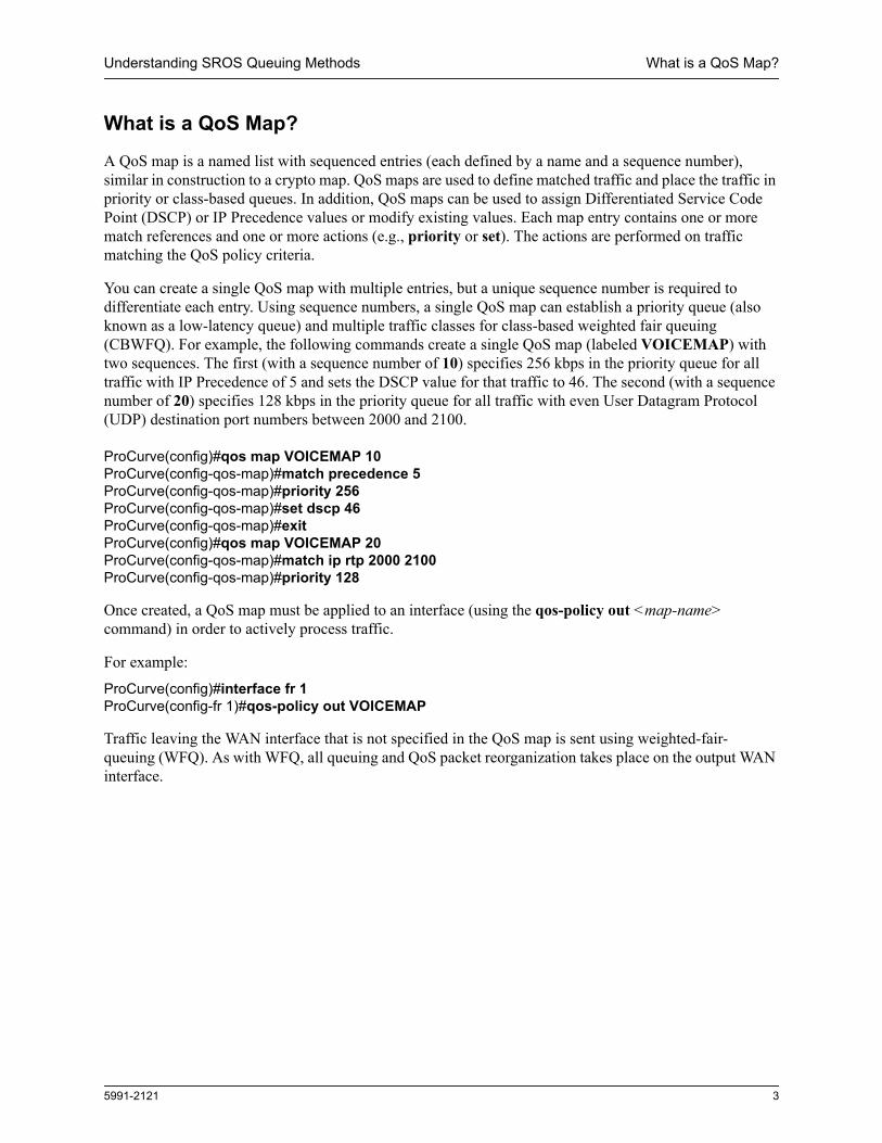
You can create a single QoS map with multiple entries, but a unique sequence number is required to differentiate each entry. Using sequence numbers, a single QoS map can establish a priority queue (also known as a low-latency queue) and multiple traffic classes for class-based weighted fair queuing (CBWFQ). For example, the following commands create a single QoS map (labeled VOICEMAP) with two sequences. The first (with a sequence number of 10) specifies 256 kbps in the priority queue for all traffic with IP Precedence of 5 and sets the DSCP value for that traffic to 46. The second (with a sequence number of 20) specifies 128 kbps in the priority queue for all traffic with even User Datagram Protocol (UDP) destination port numbers between 2000 and 2100.
ProCurve(config)#qos map VOICEMAP 10ProCurve(config-qos-map)#match precedence 5ProCurve(config-qos-map)#priority 256ProCurve(config-qos-map)#set dscp 46ProCurve(config-qos-map)#exitProCurve(config)#qos map VOICEMAP 20ProCurve(config-qos-map)#match ip rtp 2000 2100 ProCurve(config-qos-map)#priority 128
Once created, a QoS map must be applied to an interface (using the qos-policy out <map-name> command) in order to actively process traffic.
For example:
ProCurve(config)#interface fr 1ProCurve(config-fr 1)#qos-policy out VOICEMAP
Traffic leaving the WAN interface that is not specified in the QoS map is sent using weighted-fair- queuing (WFQ). As with WFQ, all queuing and QoS packet reorganization takes place on the output WAN interface.

DSCP/Precedence Values Understanding SROS Queuing Methods
4 5991-2121
DSCP/Precedence Values
Private IP networks provide the best environment for controlling all QoS handling. The bandwidth and all the equipment that make up the network are under the customer’s control. Each piece can be programmed according to the needs of the network. Public IP networks, however, are a less than ideal environment for proper QoS handling. RFC791 created a single octet (labeled Type of Service) to help with the difficulty of trying to provide QoS handling in IP networks.
According to RFC791, the Type of Service field contains the following bits:
The three-bit precedence values (0 through 7) are specified as:
111 Network Control Packets110 Internetwork Control Packets101 Critical Traffic100 Flash Override011 Flash010 Immediate Servicing001 Priority Traffic000 Routine Data
The precedence values provide network routers with information about what kind of traffic is contained in the IP packet. Based on the precedence values, some networks (when supported) can offer special handling to certain packets. In addition, providing precedence values to critical traffic (such as route information) ensures that critical packets will always be delivered regardless of network congestion. This traffic is often critical to network and internetwork operation. In general, the higher the precedence value, the more important the traffic and the better handling it should receive in the network. It is important to remember that not all equipment in the public IP network will be configured to recognize and handle precedence values. While it is a good idea to set the values for critical traffic, it does not guarantee special handling.
In addition to the precedence values, RFC791 specifies bits for delay, throughput, and reliability to help balance the needs of particular traffic types when traveling on the IP network infrastructure. When these bits are set to 0, they are handled with normal operation. When set to 1, each bit specifies premium handling for that parameter. For example, a 1 in the delay position indicates that the traffic is delay sensitive and care should be taken to minimize delay. A 1 in the throughput position indicates that the traffic has higher bandwidth requirements that should be met. A 1 in the reliability position indicates that the traffic is sensitive to delivery issues and care should be taken to ensure proper delivery with all packets of this type. These extra bits are rarely used because it is difficult to balance the cost and benefits of each parameter (especially when more than one bit is set to 1).
0 1 2 3 4 5 6 7
DelayThroughput
Reliability
UnusedPrecedence

Understanding SROS Queuing Methods DSCP/Precedence Values
5991-2121 5
The Differentiated Services (DS) or DiffServ model was created in RFC2474 and 2475 to build on the original Type of Service field by creating a six-bit sequence (combining the precedence value with the delay, throughput, and reliability bits). This six-bit sequence increased the number of available values from 8 to 64. The DiffServ model introduced a new concept to QoS in the IP network environment: per-hop behaviors (PHBs). The PHB premise is that pieces of equipment using the DiffServ model have an agreed upon set of rules (PHB types) for handling certain network traffic. Though the RFC explicitly defines what each PHB should be capable of, it does not restrict vendor-specific implementation of the PHBs. Each vendor is free to decide how their network product implements the various defined PHBs.
According to RFC2474, the DS field contains the following bits:
Equipment following the DiffServ model (DS-compliant nodes) must use the entire six-bit DSCP value to determine the appropriate PHB. The PHBs are defined as the following:
• Default PHB • Class Selector PHB• Assured Forwarding PHB (RFC2597)• Expedited Forwarding PHB (RFC2598)
Default PHBAll DS-compliant nodes must provide a Default PHB to offer best-effort forwarding service. For Default PHBs, the DSCP value is 0. Any packet that does not contain a standardized DSCP should be mapped to the Default PHB and handled accordingly.
Class Selector PHBIn the Class Selector PHB, the first three bits in the DSCP value are used for backwards compatibility to systems implementing IP Precedence. In this scenario, all but the first three bits of the DS field are set to 0. This compatibility requires DS-compliant nodes to provide the same data services provided by nodes implementing IP Precedence. The following table is a comparison of IP Precedence values to their corresponding DSCP values.
IP PrecedenceValue (bits) DSCP Value (bits)
0 (000) 0 (000000)1 (001) 8 (001000)2 (010) 16 (010000)3 (011) 24 (011000)4 (100) 32 (100000)5 (101) 40 (101000)6 (110) 48 (110000)7 (111) 56 (111000)
0 1 2 3 4 5 6 7
Unused*Differentiated Service Code Point
* The previously unused bits in the DS field are now used for congestion control and are not discussed in this document.
DSCP/Precedence Values Understanding SROS Queuing Methods
6 5991-2121
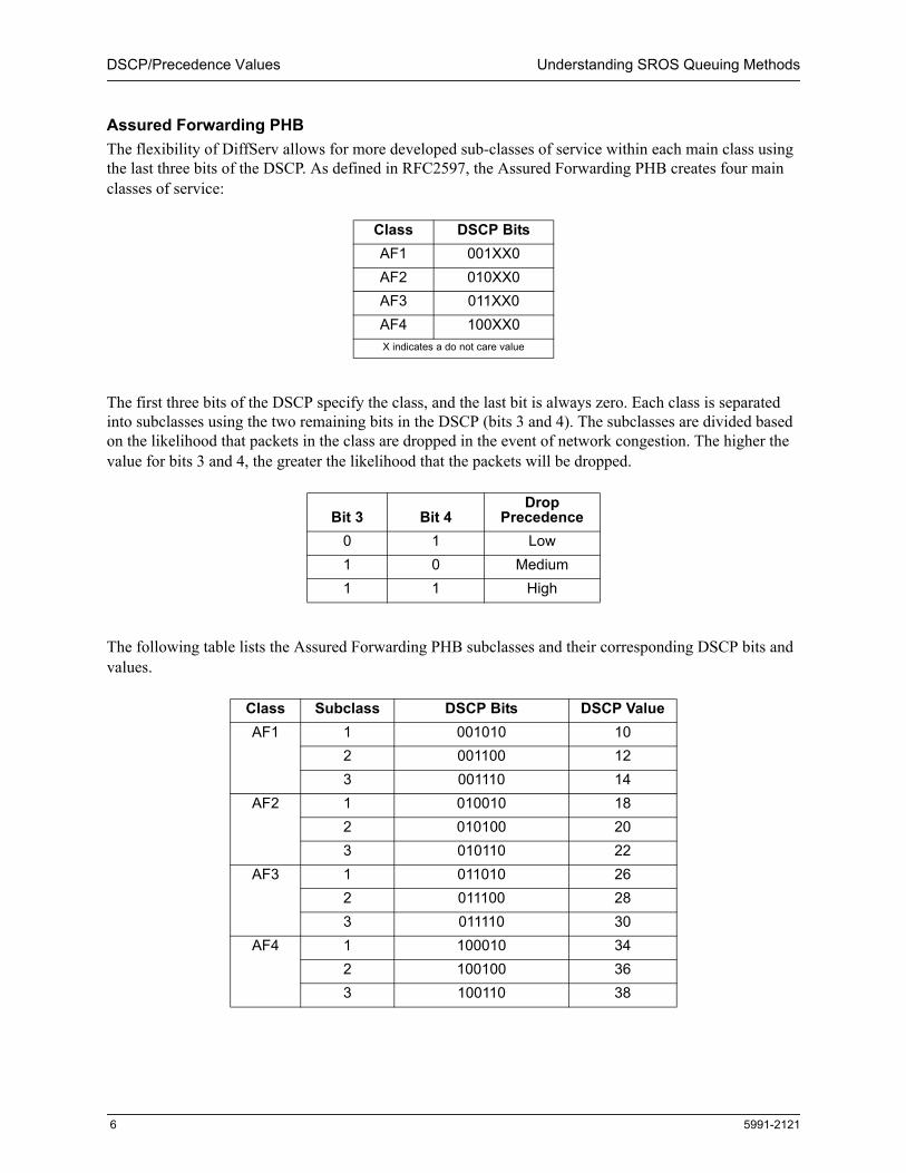
Assured Forwarding PHBThe flexibility of DiffServ allows for more developed sub-classes of service within each main class using the last three bits of the DSCP. As defined in RFC2597, the Assured Forwarding PHB creates four main classes of service:
The first three bits of the DSCP specify the class, and the last bit is always zero. Each class is separated into subclasses using the two remaining bits in the DSCP (bits 3 and 4). The subclasses are divided based on the likelihood that packets in the class are dropped in the event of network congestion. The higher the value for bits 3 and 4, the greater the likelihood that the packets will be dropped.
The following table lists the Assured Forwarding PHB subclasses and their corresponding DSCP bits and values.
Class DSCP BitsAF1 001XX0AF2 010XX0AF3 011XX0AF4 100XX0X indicates a do not care value
Bit 3 Bit 4Drop
Precedence0 1 Low1 0 Medium1 1 High
Class Subclass DSCP Bits DSCP ValueAF1 1 001010 10
2 001100 123 001110 14
AF2 1 010010 182 010100 203 010110 22
AF3 1 011010 262 011100 283 011110 30
AF4 1 100010 342 100100 363 100110 38

Understanding SROS Queuing Methods Creating Priority Queues
5991-2121 7
Expedited Forwarding PHBRFC2598 created a new DiffServ PHB intended to provide the best service possible on an IP network. Packets using the Expedited Forwarding PHB markings should be provided service to reduce latency, jitter, and dropped packets, and be guaranteed bandwidth during the entire end-to-end transmission through the network. The DSCP value for the Expedited Forwarding PHB is 46 (DSCP bits are 101110).
Creating Priority Queues
The priority queue provides a high-priority, low-latency queue, giving the traffic the highest priority. If no traffic is present in any other queue, priority traffic is allowed to burst up to the interface rate; otherwise, priority traffic above the specified bandwidth is dropped. Priority queues are intended for constant bit rate (CBR) traffic such as voice (due to the rate limiting). Non-CBR traffic typically does not respond well to packet dropping when it is rate limited, so the transfer rate can be less efficient.
The sum of the bandwidths reserved by priority commands for all entries of a QoS map cannot exceed the available bandwidth on the interface (calculated by the total interface bandwidth minus the max-reserved-bandwidth rate specified for the interfaces to which the QoS map is applied). Priority bandwidth is guaranteed bandwidth (in kbps).
Configuring Priority (Low-Latency) Queues
There are four basic steps when setting up priority queues:
Step 1: Create the QoS MapTo create the QoS map, use the qos map command at the Global command prompt. Please note that the map name (VOICE in the example below) and the sequence number (10 in this example) can be replaced with entries of your choosing. Each QoS map can have the same name with different sequence numbers. The router checks the QoS maps for a match, beginning with the lowest sequence number.ProCurve(config)#qos map VOICE 10ProCurve(config-qos-map)#
Step 2: Define MatchesThe following command matches this QoS map to traffic using the access list MY_VOICE:ProCurve(config-qos-map)#match list MY_VOICE
Step 3: Set the Maximum Bandwidth for the QueueBandwidth in a priority queue can be specified as an absolute value (using the priority command) or as a percentage of the total interface bandwidth (using the priority percent command). When possible, use the priority command to specify an absolute amount of bandwidth (in kbps) for the priority queue. The priority percent command can be used in applications with multilink interfaces to
Note Weighted-fair-queuing (WFQ) must be enabled on an interface to use priority queuing. By default, WFQ is enabled for all interfaces with maximum bandwidths equivalent to T1/E1 and below.

Configuring Priority (Low-Latency) Queues Understanding SROS Queuing Methods
8 5991-2121
avoid having the QoS map disabled (due to inadequate interface bandwidth) in the event that one link in the multilink bundle fails (see Setting the Bandwidth for a Queue on a Multilink Interface on page 8).
The following command provides 64 kbps of bandwidth in a priority queue for traffic matching the defined pattern:ProCurve(config-qos-map)#priority 64 When determining the priority percent <value> entry, use the following formula:
where Bandwidth is the minimum amount of bandwidth needed for the traffic (in kbps).Line Rate is the data rate configured on the interface (for example, 8 DS0s (64 kbps per DS0)
on a T1 equals a line rate of 512 kbps).
For example, to specify 80 kbps of data on an interface with a total of 512 kbps of available bandwidth, enter the following command:
ProCurve(config-qos-map)#priority percent 16
Setting the Bandwidth for a Queue on a Multilink InterfaceMultilink protocols such as Multilink PPP (MLPPP) and Multilink Frame Relay (MLFR) increase the total bandwidth of a connection by bundling multiple carrier access lines into a single logical connection. Because carrier lines may go down and change the current available bandwidth, allocating bandwidth on a multilink interface requires special consideration.
For example, an MLPPP connection with two T1 lines provides 3.0 Mbps of bandwidth. If you set max-reserved-bandwidth to 75, you can allocate 2.25 Mbps of the interface bandwidth to QoS queues. Consider the following priority queuing scenario:
In this scenario, if one of the T1 lines fails, the connection only has 1.5 Mbps of available bandwidth of the original guaranteed 2.25 Mbps. Interfaces are evaluated every 30 seconds to verify that there is sufficient available bandwidth for the QoS configuration. In this case, the QoS map would be disabled due to insufficient available bandwidth on the interface.
To help avoid this situation, consider allocating bandwidth to the multilink interface as if it had one carrier line less than the total. This is particularly true when the multilink is designed more to provide redundancy than to increase a connection’s bandwidth.
Using the priority percent command can also safeguard against a QoS map on a multilink connection from being disabled due to insufficient available bandwidth. The priority percent command provides guidelines on how to allocate available bandwidth but does not provide guaranteed bandwidth to a queue.
Priority Queue Bandwidth (in kbps)
1 1800
BandwidthLine Rate----------------------------

Understanding SROS Queuing Methods Creating Classes for CBWFQ
5991-2121 9
Consider the following priority queuing scenario using the priority percent command:
In this scenario, if one of the T1 lines fails, the connection only has 1.5 Mbps of available bandwidth of the original guaranteed 2.25 Mbps. When this occurs, the following adjustment to the QoS bandwidth allocation is made.
Though the bandwidth available for each priority queue is smaller than originally requested, the QoS map is still active and the relative priority for traffic on the interface is maintained.
Step 4: Assign a Map to the WAN Interface
The following command applies the QoS map to the output of the WAN interface: ProCurve(config-qos-map)#exit ProCurve(config)#interface ppp 1ProCurve(config-ppp 1)#qos-policy out VOICE
Creating Classes for CBWFQ
Current WFQ divides outgoing traffic into Layer 3 flows dynamically, with no user input. These flows are enqueued into individual conversation subqueues based on source and destination IP addresses, port numbers, and protocol type. Class-based queuing allows users to configure a type of traffic and have it enqueued onto a reserved subqueue. Keep in mind that all low-latency traffic (configured using the priority command) takes precedence over class-based traffic.
Unlike low-latency queuing, class-based queuing does not operate as a rate limiter. All classes are allowed to exceed the configured rate when enough traffic that matches the class is present, as long as the overall traffic does not exceed the total bandwidth of the interface. When exceeding the configured rate, the relative weight between the classes is maintained while all classes are transmitting.
QoS Policies Applied to Interfaces Using CBWFQ
When a QoS policy is applied to an interface, it may be disabled if the interface bandwidth is not adequate to support the requested bandwidth on the QoS map set. Once the bandwidth problem is resolved, the map will be enabled.
Priority Queue Percent Bandwidth (in kbps)
1 80 1800
Priority Queue PercentBandwidth in kbps
(during normal operation)Bandwidth in kbps(with a single T1)
1 80 1800 900
Note Apply a QoS map name (not a sequence number) to the WAN interface. All QoS maps with the same name are searched by the interface in order, based on the sequence number (from lowest to highest). The same QoS map can be applied to multiple WAN interfaces.

Configuring CBWFQ Understanding SROS Queuing Methods
10 5991-2121
The total bandwidth between all priority entries and class-based entries (bandwidth) in a QoS map set should not be configured beyond the specified max-reserved-bandwidth (default 75 percent) on the interface to which the QoS policy is applied (using the qos-policy command), or the map will be disabled. Even with the configuration limit, class-based queues can still use more than the max-reserved-bandwidth limitation, up to 100 percent of the bandwidth, if enough traffic is present.
When the configured QoS map is applied to a physical interface, the Secure Router OS displays bandwidth information for the map and the physical interface. For example, a Frame Relay interface (fr 1) has been bound to an E1 interface (e1 1/1). Applying the QoS map (MyMapA) to the Frame Relay interface (fr 1) produces the following status message:
2005.08.09 07:28:22 QOS.INTERFACE QOS policy "MyMapA" requires 1288 kbps of bandwidth and 1488 kbps is now available for interface fr 1 -> the QOS policy for this port has been forced ACTIVE.
This status message displays the total bandwidth specified in the QoS map (1288 kbps) and the available interface bandwidth using the total line rate configured on the interface (1488 kbps).
The bandwidth requirements are rechecked when any of the following parameters change:
1. A priority or class-based entry is added to, deleted from, or changed in a QoS map set.2. The interface bandwidth is changed by the bandwidth command on the interface. This manual override
does not have to match the actual bandwidth provided by the interface.3. A QoS policy is applied to an interface.4. A bind is created that includes an interface with a QoS policy. 5. The interface queuing method is changed to “fair-queue” to use weighted fair queuing.6. The interface operational status changes.7. The interface bandwidth changes for other reasons (for example, when an additional link in a multilink
bundle activates or deactivates).
Configuring CBWFQ
There are four basic steps when setting up CBWFQ:
Step 1: Create the QoS MapTo create the QoS map, use the qos map command at the Global command prompt. Please note that the map name (MyMap in the example below) and the sequence number (10 in this example) can be replaced with entries of your choosing. Each QoS map can have the same name with different sequence numbers. The router checks the QoS maps for a match, beginning with the lowest sequence number.ProCurve(config)#qos map MyMap 10ProCurve(config-qos-map)#
Step 2: Define ClassesClasses can be defined based on IP Precedence or DSCP values, source IP address, destination IP address, port, protocol type, destination UDP port, and bridged protocol. The following command specifies this QoS map for traffic based on IP packet precedence values:ProCurve(config-qos-map)#match precedence 5

Understanding SROS Queuing Methods Configuring CBWFQ
5991-2121 11
Step 3: Determine and Set the Bandwidth for the Queue
When determining the percent <value> entry, use the following formula:
where Bandwidth is the minimum amount of bandwidth needed for the traffic (in kbps).Line Rate is the data rate configured on the interface (for example, 8 DS0s (64 kbps per
DS0) on a T1 equals a line rate of 512 kbps).
For example, to specify 80 kbps of data on an interface with a total of 512 kbps of available bandwidth, enter the following command:
ProCurve(config-qos-map 1)#bandwidth percent 16
When determining the remaining percent <value> entry, use the following formula:
where Bandwidth is the minimum amount of bandwidth needed for the traffic (in kbps).max-reserved-bandwidth specifies the percentage of the total line rate available for use by QoS. Line Rate is the total data rate configured on the interface (for example,
8 DS0s (64 kbps per DS0) on a T1 equals a line rate of 512 kbps).Priority Traffic is the amount of bandwidth reserved using the priority command.
For example, to specify 80 kbps of data on an interface with a total of 512 kbps of available bandwidth, 256 kbps reserved (using the priority command), and reserving 15 percent of the bandwidth for routing and Layer 2 protocol traffic (max-reserved-bandwidth set to 85), enter the following command:
ProCurve(config-qos-map 1)#bandwidth remaining percent 45
Setting the Bandwidth for a Queue on a Multilink InterfaceMultilink protocols such as Multilink PPP (MLPPP) and Multilink Frame Relay (MLFR) increase the total bandwidth of a connection by bundling multiple carrier access lines into a single logical connection. Because carrier lines may go down and change the current available bandwidth, allocating bandwidth on a multilink interface requires special consideration.
For example, an MLPPP connection with two T1 lines provides 3.0 Mbps of bandwidth. If you set max-reserved-bandwidth to 75, you can allocate 2.25 Mbps of the interface bandwidth to QoS queues. Consider the following CBWFQ scenario using the bandwidth command to allocate a
Note When possible, use the bandwidth <value> command to specify an absolute amount of bandwidth (in kbps) for the traffic class.
BandwidthLine Rate----------------------------
Bandwidth[(max-reserved-bandwidth)(Line Rate)] Priority Traffic–---------------------------------------------------------------------------------------------------------------------------------------------------

Configuring CBWFQ Understanding SROS Queuing Methods
12 5991-2121
specified amount of bandwidth (in kbps) for each class:
In this scenario, if one of the T1 lines fails, the connection only has 1.5 Mbps of available bandwidth of the original guaranteed 2.25 Mbps. Interfaces are evaluated every 30 seconds to verify that there is sufficient available bandwidth for the QoS configuration. In this case, the QoS map would be disabled due to insufficient available bandwidth on the interface.
To help avoid this situation, consider allocating bandwidth to the multilink interface as if it had one carrier line less than the total. This is particularly true when the multilink is designed more to provide redundancy than to increase a connection’s bandwidth.
Using the bandwidth percent or bandwidth remaining percent commands can also safeguard against a QoS map on a multilink being disabled due to insufficient available bandwidth. The bandwidth percent and bandwidth remaining percent commands provide guidelines on how to allocate available bandwidth but do not provide guaranteed bandwidth to a class. Consider the following CBWFQ scenario using the bandwidth percent command:
In this scenario, if one of the T1 lines fails, the connection only has 1.5 Mbps of available bandwidth of the original guaranteed 2.25 Mbps. When this occurs, the following adjustment to the QoS bandwidth allocation is made.
Though the bandwidth available for each class is smaller than originally requested, the QoS map is still active and the relative priority among the classes is maintained.
Class Bandwidth (in kbps)
Class 1 300
Class 2 600
Class 3 600
Class 4 750
Class Percent Bandwidth (in kbps)
Class 1 10 300
Class 2 20 600
Class 3 20 600
Class 4 25 750
Class PercentBandwidth in kbps
(during normal operation)Bandwidth in kbps(with a single T1)
Class 1 10 300 113
Class 2 20 600 225
Class 3 20 600 225
Class 4 25 750 282

Understanding SROS Queuing Methods Configuring CBWFQ
5991-2121 13
Now, Consider the following CBWFQ scenario using the bandwidth remaining percent command:
In this scenario, if one of the T1 lines fails, the connection only has 1.5 Mbps of available bandwidth of the original guaranteed 2.25 Mbps. When this occurs, the following adjustment to the QoS bandwidth allocation is made.
Though the bandwidth available for each class is smaller than originally configured, the QoS map is still active and the relative priority among the classes is maintained.
Step 4: Assign a QoS Map to WAN Interface
The following command applies the QoS map (MyMap) to the output of the WAN interface:
ProCurve(config-qos-map)#exit ProCurve(config)#interface ppp 1ProCurve(config-fr 1)#qos-policy out MyMap
ClassRemaining
PercentBandwidth in kbps
(during normal operation)
Class 1 13 292.5
Class 2 27 607.5
Class 3 27 607.5
Class 4 33 742.5
ClassRemaining
PercentBandwidth in kbps
(during normal operation)Bandwidth in kbps(with a single T1)
Class 1 13 292.5 195
Class 2 27 607.5 405
Class 3 27 607.5 405
Class 4 33 742.5 495
Note Apply a QoS map name (not a sequence number) to the WAN interface. All QoS maps with the same name are searched by the interface in order, based on the sequence number (from lowest to highest). The same QoS map can be applied to multiple WAN interfaces.

Command Definitions Understanding SROS Queuing Methods
14 5991-2121
Command Definitions
Now that you have a basic understanding of the setup involved, refer to the following information to further your understanding of QoS commands.
Match CommandsThe match commands specify a parameter to which incoming packets (on an interface with the active QoS policy) are compared. QoS maps have a matching selector and an action (how the traffic should be handled). The special handling instructions contained in the QoS map action are applied to all packets that contain the specified match parameter. The following lists the available QoS map match parameters.
match dscp <0-63>Matches IP packets with the specified DSCP value in the IP header. DSCP values (as specified by RFC2474) are contained in six bits of the IP header and indicate when a packet requires special handling to help ensure QoS. For more details on determining DSCP values, refer to DSCP/Precedence Values on page 4.
match precedence <0-7>Matches IP packets with the specified IP Precedence value in the IP header. IP Precedence values (as specified by RFC791) are contained in three bits of the IP header and indicate when a packet requires special handling to help ensure QoS. For more details on determining IP Precedence values, refer to DSCP/Precedence Values on page 4.
match ip rtp <starting port number> <ending port number> [all]Matches IP packets that contain even UDP port numbers that fall in the specified range. The optional keyword all is used to match even and odd UDP port numbers in the specified range.
match protocol bridgeMatches IP packets that are being bridged by the router.
match protocol bridge netbeuiMatches only NetBIOS Extended User Interface (NetBEUI) traffic being bridged by the router.
match list <list name>Matches all packets selected by a configured access list. The Secure Router OS access lists are traffic selectors that include a matching parameter (to select the traffic) and an action statement (to either permit or deny the matched traffic). The special handling instructions defined in the QoS map are applied to all packets allowed by the specified access list.
Priority CommandThe priority command provides a low-latency queue that prioritizes the selected traffic above all other user traffic. If no other traffic is present in any other queue on the interface, priority traffic is allowed to burst up to the interface rate. Otherwise, priority traffic above the specified bandwidth will be dropped. Priority queues are intended for constant bit rate traffic such as voice (due to the rate limiting). The following is a list of available priority variations.

Understanding SROS Queuing Methods Bandwidth Commands
5991-2121 15
priority unlimitedThe unlimited keyword specifies that no rate limiting is performed on traffic contained in the priority queue. This option should be used with caution because any excessive traffic in the priority queue has the potential to use all of the available bandwidth on the interface.
priority <value> [burst]Specifies an absolute value (in kbps) allocated to the priority queue on the interface. If bandwidth sharing is needed on the interface because traffic is present in other queues on the interface, priority traffic above the specified bandwidth value is dropped. The optional keyword burst specifies the maximum burst size (in bytes) for traffic in this priority queue. This keyword should be left unconfigured for optimal performance.
priority percent <percent>Specifies the bandwidth allocated to the priority queue on the interface based on a percentage of the total bandwidth available. If bandwidth sharing is needed on the interface because traffic is present in other queues on the interface, priority traffic above the specified bandwidth value is dropped. When determining the percent <value> entry, use the following formula:
where Bandwidth is the minimum amount of bandwidth needed for the traffic (in kbps).Line Rate is the data rate configured on the interface (for example, 8 DS0s (64 kbps per
DS0) on a T1 equals a line rate of 512 kbps).
Bandwidth CommandsThe bandwidth commands are used to specify the bandwidth allocation for individual traffic classes (for CBWFQ). Bandwidth for CBWFQ is allocated from the available interface bandwidth minus any bandwidth allocated to a priority queue (using the priority command). The following lists the available bandwidth commands.
bandwidth <value>Specifies an absolute bandwidth (in kbps) allocated to the user defined class on the interface. If bandwidth sharing is needed on the interface because traffic is present in other queues on the interface, class traffic above the specified bandwidth value is dropped.
bandwidth percent <percent>Specifies the bandwidth allocated to the user defined class on the interface based on a percentage of the total bandwidth available. If bandwidth sharing is needed on the interface because traffic is present in other queues on the interface, class traffic above the specified bandwidth value is dropped. When determining the percent <percent> entry, use the following formula:
where Bandwidth is the minimum amount of bandwidth needed for the traffic (in kbps).Line Rate is the data rate configured on the interface (for example, 8 DS0s (64 kbps per
DS0) on a T1 equals a line rate of 512 kbps).
BandwidthLine Rate----------------------------
BandwidthLine Rate----------------------------

Set Commands Understanding SROS Queuing Methods
16 5991-2121
bandwidth remaining percent <value>Specifies guidelines for using the remaining bandwidth available on an interface after priority traffic and CBWFQ traffic (specified using the bandwidth percent command). Since all bandwidth statements in the QoS map must use the same units (kbps, percent, or remaining percent), when using remaining percent, all bandwidth statements share unallocated bandwidth on the interface at a level proportional to their specified values. Using the bandwidth remaining percent command to specify bandwidth for a class does not guarantee absolute bandwidth.When determining the remaining percent <value> entry, use the following formula:
where Bandwidth is the minimum amount of bandwidth needed for the traffic (in kbps).max-reserved-bandwidth specifies the percentage of the total line rate available for use by QoS. Line Rate is the total data rate configured on the interface (for example, 8 DS0s (64
kbps per DS0) on a T1 equals a line rate of 512 kbps).Priority Traffic is the amount of bandwidth reserved using the priority command.
Set CommandsThe set commands are used to set the QoS bits (DSCP or IP Precedence) in the IP header for all packets handled by the QoS map. Setting the QoS bits on transmitted packets provides special handling instructions for the next hop router. The following lists the available set commands.
set dscp <0-63>Sets the DSCP bits in the IP header to the specified value. DSCP values (as specified by RFC2474) are contained in six bits of the IP header and indicate when a packet requires special handling to help ensure QoS. For more details on determining DSCP values, refer to DSCP/Precedence Values on page 4.
set precedence <0-7>Sets the IP Precedence bits in the IP header to the specified value. IP Precedence values (as specified by RFC791) are contained in three bits of the IP header and indicate when a packet requires special handling to help ensure QoS. For more details on determining IP Precedence values, refer to DSCP/Precedence Values on page 4.
Show CommandsThe show commands provide statistical information for configured QoS maps. This information can be helpful when troubleshooting QoS problems or verifying configurations. The following lists the available QoS show commands.
show qos mapDisplays configuration information and the number of packet matches for all configured QoS maps.
show qos map <mapname> <sequence number>Displays configuration information and the number of packet matches for the specific map (using the map name) or a single map entry (using the map name and sequence number).
Bandwidth[(max-reserved-bandwidth)(Line Rate)] Priority Traffic–---------------------------------------------------------------------------------------------------------------------------------------------------
Understanding SROS Queuing Methods Configuration Example
5991-2121 17
show qos map interface <interface>Displays any priority queue discards for the QoS map applied to the specified interface and the number of packet matches. All packet matches will increment the count regardless of whether the packet is delivered or dropped (due to rate limiting).
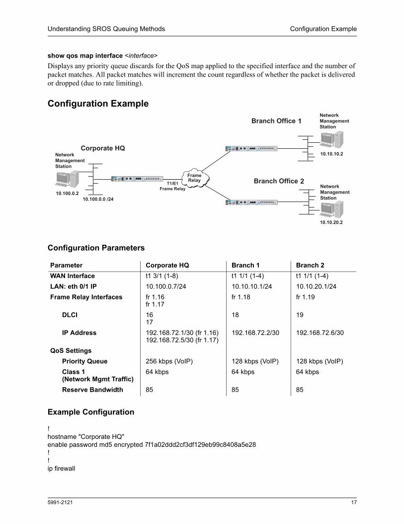
Configuration Example
Configuration Parameters
Example Configuration
!hostname "Corporate HQ"enable password md5 encrypted 7f1a02ddd2cf3df129eb99c8408a5e28!!ip firewall
Parameter Corporate HQ Branch 1 Branch 2WAN Interface t1 3/1 (1-8) t1 1/1 (1-4) t1 1/1 (1-4)LAN: eth 0/1 IP 10.100.0.7/24 10.10.10.1/24 10.10.20.1/24Frame Relay Interfaces fr 1.16
fr 1.17fr 1.18 fr 1.19
DLCI 16 17
18 19
IP Address 192.168.72.1/30 (fr 1.16)192.168.72.5/30 (fr 1.17)
192.168.72.2/30 192.168.72.6/30
QoS SettingsPriority Queue 256 kbps (VoIP) 128 kbps (VoIP) 128 kbps (VoIP)Class 1 (Network Mgmt Traffic)
64 kbps 64 kbps 64 kbps
Reserve Bandwidth 85 85 85
T1/E1Frame Relay
Frame�Relay 2
1
10.10.20.2
10.10.10.2
NetworkManagementStation
NetworkManagementStation10.100.0.0 /24
10.100.0.2
NetworkManagementStation

Example Configuration Understanding SROS Queuing Methods
18 5991-2121
no ip firewall alg h323ip firewall alg sip!!qos map CLASS 1 match ip rtp 2000 2100 priority 256qos map CLASS 2 match list MGMT bandwidth percent 13!interface eth 0/1 ip address 10.100.0.7 255.255.255.0 no shutdown!!!interface t1 3/1 tdm-group 1 timeslots 1-8 speed 64 no shutdown!!!interface fr 1 point-to-point frame-relay lmi-type ansi qos-policy out CLASS max-reserved-bandwidth 85 no shutdown bind 1 t1 3/1 1 frame-relay 1!interface fr 1.16 point-to-point frame-relay interface-dlci 16 ip address 192.168.72.1 255.255.255.252 !interface fr 1.17 point-to-point frame-relay interface-dlci 17 ip address 192.168.72.5 255.255.255.252 !!!ip access-list extended MGMT permit ip host 10.100.0.2 host 10.10.10.2 permit ip host 10.100.0.2 host 10.10.20.2 !!!ip route 10.10.10.0 255.255.255.0 fr 1.16ip route 10.10.20.0 255.255.255.0 fr 1.17!!end
Copyright 2006 Hewlett-Packard Development Company, LP. The information contained herein is subject to change without notice.