unit 1 industrial frames
TRANSCRIPT

UNIT 1 INDUSTRIAL FRAMES
Single storey buildings are the largest sector of the UK structural steelwork market, representing
upwards of 60% of total activity. These buildings are typically used for workshops, factories,
industrial and distribution warehouses and retail and leisure. Referred to colloquially as ‘sheds’,
sizes vary from small workshops of just a few hundred square metres up to massive distribution
warehouses covering over one hundred thousand square metres.
Steel dominates the framing systems used in this sector with a market share of approximately
90%. Whilst most single-storey buildings are relatively straightforward building projects,
increasing levels of specialisation by steelwork contractors and other supply chain members
have, in recent years, led to huge improvements in quality, cost and delivery performance of
single-storey steel buildings. These improvements have been achieved through increasingly
efficient use of the portal frame by design-and-build steelwork contractors, improved project
planning, and active supply chain management by main contractors.
This article deals specifically with single storey industrial buildings. Single storey buildings in
other sectors are addressed in other articles, e.g. retail and leisure.
Configurations, roof structure, roof bracings. • Roof structure: decking, purlins, rafters. • Column
base plates, vertical bracing of longitudinal walls and gables, wall elements (cladding, posts,
columns, rails, cassettes, bracings). • Classification (second order effects) of structures • Frames,
detailing, space behaviour of halls. • Design of crane runway beams.
Function protection against climatic effects arrangement of operation = traffic tracks Categories of halls: •
Standard ⊕ low cost (budget price) ⊕ fast available - provided from stock Θ lack of flexibility (difficult to adapt) Θ light cranes only (if any…) • Purpose-made ... suitable for given production, use (e.g. heavy cranes, lightening,
ventilation ...)

UNIT 2
RC STRUCTURES ELEMENTS
Beam
A structural member that support transverse (Perpendicular to the axis of the member)
load is called a beam. Beams are subjected to bending moment and shear force. Beams are
also known as flexural or bending members. In a beam one of the dimensions is very large
compared to the other two dimensions. Beams may be of the following types:
a. Singly or doubly reinforced rectangular beams
Fig 1: Singly reinforced rectangular beam

Fig 2: Doubly reinforced rectangular beam

b. Singly or doubly reinforced T-beams
Fig 3: Singly reinforced T beam
Fig 4: Doubly reinforced T beam
c. Singly or doubly reinforced L-beams

Fig 5: Singly reinforced L beam
Fig 6: Doubly reinforced L beam
General specification for flexure design of beams
Beams are designed on the basis of limit state of collapse in flexure and checked for
other limit states of shear, torsion and serviceability. To ensure safety the resistance to bending,
shear, torsion and axial loads at every section should be greater than the appropriate values at
that produced by the probable most unfavourable combination of loads on the structure using
the appropriate safety factors. The following general specifications and practical requirements
are necessary for designing the reinforced cement concrete beams.
a. Selection of grade of concrete
Apart from strength and deflection, durability shall also be considered to
select the grade of concrete to be used. Table 5 of IS 456:2000 shall be referred for
the grade of concrete to be used. In this table the grade of concrete to be used is
recommended based on the different environmental exposure conditions. b. Selection of grade of steel
Normally Fe 250, Fe 415 and Fe 500 are used. In earthquake zones and
other places where there are possibilities of vibration, impact, blast etc, Fe 250 (mild
steel) is preferred as it is more ductile. c. Size of the beam
The size of the beam shall be fixed based on the architectural requirements,
placing of reinforcement, economy of the formwork, deflection, design moments and
shear. In addition, the depth of the beam depends on the clear height below the beam
and the width depends on the thickness of the wall to be constructed below the beam.
The width of the beam is usually equal to the width of the wall so that there is no
projection or offset at the common surface of contact between the beam and the wall.
The commonly used widths of the beam are 115 mm, 150 mm, 200 mm, 230 mm, 250 mm, 300 mm.
d. Cover to the reinforcement

Cover is the certain thickness of concrete provided all round the steel bars to
give adequate protection to steel against fire, corrosion and other harmful elements
present in the atmosphere. It is measured as distance from the outer concrete surface
to the nearest surface of steel. The amount of cover to be provided depends on the
condition of exposure and shall be as given in the Table 16 of IS 456:2000. The
cover shall not be less than the diameter of the bar. e. Spacing of the bars
The details of spacing of bars to be provided in beams are given in clause
26.3.2 of IS 456. As per this clause the following shall be considered for spacing of
bars.
The horizontal distance between two parallel main bars shall usually be not less than the greatest of the following i. Diameter of the bar if the diameters are equal ii. The diameter of the larger bar if the diameters are unequal iii. 5mm more than the nominal maximum size of coarse aggregate
Greater horizontal spacing than the minimum specified above should be
provided wherever possible. However when needle vibrators are used, the
horizontal distance between bars of a group may be reduced to two thirds the
nominal maximum size of the coarse aggregate, provided that sufficient space is left
between groups of bars to enable the vibrator to be immersed.
Where there are 2 or more rows of bars, the bars shall be vertically in line
and the minimum vertical distance between the bars shall be of the greatest of the
following
i. 15 mm ii. Maximum size of aggregate iii. Maximum size of bars
Maximum distance between bars in tension in beams:
The maximum distance between parallel reinforcement bars shall not be greater than the values given in table 15 of IS 456:2000.
2.3 General Aspects of Serviceability:
The members are designed to withstand safely all loads liable to act on it throughout
its life using the limit state of collapse. These members designed should also satisfy the
serviceability limit states. To satisfy the serviceability requirements the deflections and
cracking in the member should not be excessive and shall be less than the permissible
values. Apart from this the other limit states are that of the durability and vibrations.
Excessive values beyond this limit state spoil the appearance of the structure and affect the
partition walls, flooring etc. This will cause the user discomfort and the structure is said to
be unfit for use.

The different load comb inations and the corresponding partial safety factors to be used for the limit state of serviceability are given in Table 18 of IS 456:2000.
Limit state of serviceability for flexural members:
Deflection
The check for deflection is done through the following two methods specified by IS 456:2000 (Refer clause 42.1)
1 Empirical Method
In this method, the deflection criteria of the member is said t o be satisfied
when the actual val ue of span to depth ratio of the member is less than the
permissible values. T he IS code procedure for calculating the permissible values
are as given below
a. Choosing the basic values of span to effective depth ratios (l/d) from the following, depending on the type of beam
1. Cantilever = 8
2. Simply supported = 20
3. Continuous = 26 b. Modify the value of basic span to depth ratio to get the allowable span to depth
ratio.
Allowable l/d = Bas ic l/d x Mt x Mc x Mf
Where, Mt = Mo ification factor obtained from fig 4 IS 456:200 0. It depends
on the area of tension reinforcement provided and the type of steel.
Mc = Modificatio n factor obtained from fig 5 IS 456:2000. Thi s depends on the area of compress ion steel used.
Mf = Reduction f actor got from fig 6 of IS 456:2000

Note: The basic values of l/d mentioned above is valid upto spans of 10m. The basic values
are multiplied by 10 / span in meters except for cantilever. For cantilevers whose span
exceeds 10 m the theoretical method shall be used.
2 Theoretical method of checking deflection
The actual deflections of the members are calculated as per procedure given
in annexure ‘C’ of IS 456:2000. This deflection value shall be limited to the
following
i. The final deflection due to all loads including the effects of temperature, creep and shrinkage shall not exceed span / 250.
ii. The deflection including the effects of temperature, creep and shrinkage
occurring after erection of partitions and the application of finishes shall not
exceed span/350 or 20 mm whichever is less.
2.6 Cracking in structural members
Cracking of concrete occurs whenever the tensile stress developed is greater than the tensile strength of concrete. This happens due to large values of the following:
1. Flexural tensile stress because of excessive bending under the applied load 2. Diagonal tension due to shear and torsion
3. Direct tensile stress under applied loads (for example hoop tension in a circular
tank)
4. Lateral tensile strains accompanying high axis compressive strains due to Poisson’s effect (as in a compression test)
5. Settlement of supports
In addition to the above reasons, cracking also occurs because of
1. Restraint against volume changes due to shrinkage, temperature creep and chemical effects.
2. Bond and anchorage failures
Cracking spoils the aesthetics of the structure and also adversely affect the
durability of the structure. Presence of wide cracks exposes the reinforcement to the
atmosphere due to which the reinforcements get corroded causing the deterioration of
concrete. In some cases, such as liquid retaining structures and pressure vessels cracks
affects the basic functional requirement itself (such as water tightness in water tank).
Permissible crack width
The permissible crack width in structural concrete members depends on the type of
structure and the exposure conditions. The permissible values are prescribed in clause
35.3.2 IS 456:2000 and are shown in table below

Table: Permissible values of crack width as per IS 456:2000
No. Types of Exposure Permissible widths of crack
at surface (mm)
1 Protected and not exposed to aggressive
0.3
environmental conditions
2 Moderate environmental conditions 0.2
Control of cracking
The check for cracking in beams are done through the following 2 methods specified in IS 456:2000 clause 43.1
1. By empirical method:
In this method, the cracking is said to be in control if proper detailing (i.e. spacing)
of reinforcements as specified in clause 26.3.2 of IS 456:2000 is followed. These
specifications regarding the spacing have been already discussed under heading general
specifications. In addition, the following specifications shall also be considered
i. In the beams where the depth of the web exceeds 750 mm, side face
reinforcement shall be provided along the two faces. The total area of such
reinforcement shall not be less than 0.1% of the web area and shall be distributed
equally on two faces at a spacing not exceeding 300 mm or web thickness
whichever is less. (Refer clause 25.5.1.3 IS456:2000)
ii. The minimum tension reinforcement in beams to prevent failure in the tension zone by cracking of concrete is given by the following
As = 0.85 fy / 0.87 fy (Refer clause 26.5.1.1 IS 456:2000)
iii. Provide large number of smaller diameter bars rather than large diameter bars of
the same area. This will make the bars well distributed in the tension zone and
will reduce the width of the cracks.
2. By crack width computations
In the case of special structures and in aggressive environmental conditions, it is
preferred to compute the width of cracks and compare them with the permissible
crack width to ensure the safety of the structure at the limit state of serviceability.
The IS 456-2000 has specified an analytical method for the estimation of surface
crack width in Annexure-F which is based on the British Code (BS : 8110)
specifications where the surface crack width is less than the permissible width, the
crack control is said to be satisfied.

2.7 Design Problems:
1. Given the following data of a simply supported T beam, check the deflection criteria by empirical method Width of the beam (b) = 230 mm Effective depth (d) = 425 mm
Effective span = 8.0 m
Area of tension steel required = 977.5 mm2
Area of tension steel provided = 1256 mm2
Area of compression steel provided = 628 mm2
Type of steel = Fe 415
Width of flange (bf) = 0.9 m
Width of web (bw) = 0.3 m
Solution:
Basic ��
= 20 for simply supported beam from clause 23.2.1
Allowable � = Basic � x Mt x Mc x Mf …………. (1) � �
�� =
1265 100
= 1.30%
230 425
�� =
0.58�� × �������������- ��!
�����������"��#
!�!
�� =
0.58 × 415 × 977.5
= 187.3 1256
From fig 4, for Pt = 1.3%, fs = 187.5 N/mm2
Mt = 1.1 ………. (a)
� = 628 × 100 = 0.65% & 230 × 425
From fig 5, for Pc = 0.65%, Mc = 1.15 ………………(b)
From fig 6, for ''() =
**.+*
.,* = 0.33, Mf = 0.80 ………(c)
Substituting a, b and c in equation (1)
�
We get allowable � = 20 x 1.1 x 1.15 x 0.80 = 20.2

� *../0 < � Actual � = - = 18.82 allowable �
Hence OK
2. A rectangular beam continuous over several supports has a width of 300 mm and overall depth of 600 mm. The effective length of each of the spans of the beam is 12.0 m. The effective cover is 25 mm. Area of compression steel provided is 942 mm
2 and area
of tension steel provided is 1560 mm2. Adopting Fe 500 steel estimate the safety of
the beam for deflection control using the empirical method
Solution:
� �
Allowable � = Basic � x Mt x Mc x Mf …………. (1)
Basic ��
= 26 as the beam is continuous
� = 0.58�� × �������������- ��! �
�����������"��# !�!
� = 0.58 × 500 × 1560 = 290 �
1560
From fig 4, for fs = 290, Pt = 0.90, Mt = 0.9……….(a)
From fig 5, for Pc = 0.54%, Mc = 1.15 ……………….(b)
From fig 6, for ''() = 1.0, Mf = 1 ……………………(c)
The equation (1) shall be multiplied by
2*
. �
2*
as the span of the beam is greater �345 2/ than 10.0 m
�
2/
Allowable
�
=
2*
x 26 x 0.9 x 1.15 x 1 = 22.4
� *.060 < � Actual � =
2/ = 20.86
allowable �
Hence deflection control is satisfied.

3. Find the effective depth based on the deflection criteria of a cantilever beam of 6m
span. Take fy = 415 N/mm2, Pt = 1%, Pc = 1%.
Solution:
� �
Allowable � = Basic � x Mt x Mc x Mf �
Basic � = 7 for cantilever beam 789:;<=>:;�
Assume 7893:?@>�;�
= 1.0
fs = 0.58 x 415 x 1= 240.7
From fig 4, for fs = 240, Pt = 1%, Mt = 1.0
From fig 5, for Pc = 1%, Mc = 1.25
From fig 6, for ''() = 1.0, Mf = 1
�
Allowable � = 7 x 1.0 x 1.25 x 1.0 = 8.75
! = � A*** -.60 = -.60 = 685 mm
4. A simply supported beam of rectangular cross section 250mm wide and 450mm overall
depth is used over an effective span of 4.0m. The beam is reinforced with 3 bars of
20mm diameter Fe 415 HYSD bars at an effective depth of 400mm. Two anchor bars
of 10mm diameter are provided. The self weight of the beam together with the dead
load on the beam is 4 kN/m. Service load acting on the beam is 10 kN/m. Using M20
grade concrete, compute a. Short term deflection b. Long term deflection
Solution:
Data b = 250 mm, D = 450 mm, d = 400 mm, fy = 415 N/mm2
Ast = 3 x
B
x 202 = 942 mm
2, l = 4.0 m, D.L = 4 kN/m, Service load = 10 kN/m, .
.
Total load = 14 kN/m, fck = 20, Asc = 2 x B
x 102 = 158 mm
2
Es = 2.1 x 10⁵ , Ec = 5000 C
�&
D = 22360 N/mm2

+EFGF +H6 m = /-* = /-*
= 13.3
fcr = 0.7 C�&D = 0.7 I20 = 3.13 N/mm2
a. Short term deflection
To determine the depth of N.A Equating the moment of compression area to that of the tension area, we get
H
b * x * / = m * Ast * (d-x) ‘m’ is used to convert the steel into equivalent concrete area
250 *
HJ
= 13 * 942 * (400-x)
/ Solving, x = 155 mm from the top
M x (155/2)2
Cracked MOI Ir = /0*×200K + L + 13 x 942 (400 – 155)
250 × 155 8 4
2/ = 10.45 x 10 mm
(2) Igr = Gross MOI = /0*H.0*
K
= 18.98 x 108 mm
4
2/ (3) M = Maximum BM under service load
M= N�J
= 2.×.J
= 28 kN = 28 x 106 N-mm
- - (4) Cracked moment of inertia
Mr = OFPQRP =
+.2+×2-.,-×2*S
= 26 x 106
N-mm
�9 *.0×.0*
Lever arm = z = T! − H
V
+
200
= T400 − V = 348.34 mm
+
(5) Ieff = W ZP [XP ] G( ^
2./YT Z VT \ VT2Y \ VT G V
_
2*..0×2*S
g
2./Y` Ja×bcaa dT KeS.Ke VT2Y bff VL2M
JS×bc ecc ecc

Ieff = 14.93 x 108 mm
4
Further Ir < Ieff < Igr
(6) Maximum short term deflection
h(N�e
0 2.×L.***MJ
ai(perm)
= iFXj))
= +-. //+A*×2..,+×2*S
= 1.39 mm
0
Kw = +-. for SSB with UDL
b. Long term deflection
(1) Shrinkage deflection (acs):
acs = K3 ψcs L2
K3 = 0.125 for simply supported beam from Annexure C-3.1
ψcs = Shrinkage curvature = k. T lF8 V m
n&� = Ultimate shrinkage strain of concrete (refer 6.2.4) = 0.0003
2**×,./ = 0.942
��
=
/0*×.**
2**×20- = 0.158
�& =
/0*×.**
Pt - Pc = (0.942 – 0.158) = 0.784 This is greater than 0.25 and less than 1.0 Hence ok.
Therefore
k. = 0.72 ×
o9 Yo F
= 0.72 ×
*.,. /Y*.2 0-
Co9 I*.,./ K4 = 0.58
ψcs = *.0-×*.***+
= 3.866 x 10⁻⁷
.0*
acs = K3 ψcs L2
= 0.125 x 3.866 x 10-7
x (4000)2
= 0.773 mm
(2) Creep deflection [acc(perm)]
Creep deflection acc(perm) = aicc(perm) – ai(perm)
Where, acc(perm) = creep deflection due to permanent loads

aicc(perm) = short term deflection + creep deflection
ai(perm) = short term deflection
aicc (perm) = kN `
N�K
d
iFjXj))
iF = iF
p&; = L2qrM L2q2.AM
s = Creep coefficient = 1.6 for 28 days loading
aicc(perm) = 2.6 x short term deflection
= 2.6 x ai(perm)
= 2.6 x 1.39 = 3.614 mm
Creep deflection acc(perm) = 3.614 – 1.39 = 2.224 mm
Total long term deflection = shrinkage deflection + Creep deflection
= 0.773 + 2.224 = 3.013 mm
Total deflection = Short term deflection + Long term deflection
= 1.39 + 3.013 = 4.402 mm

LSM: DESIGN OF SLABS &COLUMNS
4.1 Pre-requisite Discussion:
A column is defined as a compression member, the effective length of which exceeds three times the least lateral dimension. Compression members, whose lengths do not exceed three
times the least lateral dimension, may be made of plain concrete. A column forms a very important component of a structure. Columns support beams which in turn support walls
and slabs. It should be realized that the failure of a column results in the collapse of the structure. The design of a column should therefore receive importance.
4.2 Introduction:
A column is a vertical structural member supporting axial compressive loads, with or without moments. The cross-sectional dimensions of a column are generally considerably less than its height. Columns support vertical loads from the floors and roof and transmit these loads to the foundations.
The more general terms compression members and members subjected to combined axial load and bending are sometimes used to refer to columns, walls, and members in concrete trusses or frames. These may be vertical, inclined, or horizontal. A column is a special case of a compression member that is vertical. Stability effects must be considered in the design of compression members. 4.3 Classification of columns
A column may be classified based on different criteria such as:
1. Based on shape
Rectangle
Square
Circular
L type
T type
+ type
2. Based on slenderness ratio or height
Short column and Long column or Short and Slender Compression Members
A compression member may be considered as short when both the slenderness ratios namely lex/D and ley/b are less than 12: Where
lex= effective length in respect of the major axis, D= depth in respect of the major axis, ley= effective length in respect of the minor axis, and b = width of the member.
It shall otherwise be considered as a slender or long compression member.

The great majority of concrete columns are sufficiently stocky (short) that slenderness can be ignored. Such columns are referred to as short columns. Short column generally fails by crushing of concrete due to axial force. If the moments induced by slenderness effects weaken a column appreciably, it is referred to as a slender column or a long column. Long columns generally fail by bending effect than due to axial effect. Long column carry less load compared to long column.
3. Based on pattern of lateral reinforcement
Tied columns with ties as laterals columns with Spiral steel as laterals or spiral columns
Majority of columns in any buildings are tied columns. In a tied column the longitudinal bars are tied together with smaller bars at intervals up the column. Tied columns may be square, rectangular, L-shaped, circular, or any other required shape. Occasionally, when high strength and/or high ductility are required, the bars are placed in a circle, and the ties are replaced by a bar bent into a helix or spiral. Such a column, called a spiral column. Spiral columns are generally circular, although square or polygonal shapes are sometimes used. The spiral acts to restrain the lateral expansion of the column core under high axial loads and, in doing so, delays the failure of the core, making the column more ductile. Spiral columns are used more extensively in seismic regions. If properly designed, spiral column carry 5% extra load at failure compared to similar tied column.
4. Based on type of loading
Axially loaded column or centrally or concentrically loaded column (Pu)
A column subjected to axial load and unaxial bending (Pu + Mux) or (P + Muy) A column subjected to axial load and biaxial bending (Pu + Mux + Muy)
5. Based on materials

4.4 Behavior of Tied and Spiral Columns
Figure shows a portion of the core of a spiral column. Under a compressive load, the concrete in this column shortens longitudinally under the stress and so, to satisfy Poisson’s ratio, it expands laterally. In a spiral column, the lateral expansion of the concrete inside the spiral (referred to as the core) is restrained by the spiral. This stresses the spiral in tension. For equilibrium, the concrete is subjected to lateral compressive stresses. In a tied column in a non seismic region, the ties are spaced roughly the width of the column apart and, as a result, provide relatively little lateral restraint to the core. Outward pressure on the sides of the ties due to lateral expansion of the core merely bends them outward, developing an insignificant hoop-stress effect. Hence, normal ties have little effect on the strength of the core in a tied column. They do, however, act to reduce the unsupported length of the longitudinal bars, thus reducing the danger of buckling of those bars as the bar stress approaches yield. load-deflection diagrams for a tied column and a spiral column subjected to axial loads is shown in figure. The initial parts of these diagrams are similar. As the maximum load is reached, vertical cracks and crushing develop in the concrete shell outside the ties or spiral, and this concrete spalls off. When this occurs in a tied column, the capacity of the core that remains is less than the load on the column. The concrete core is crushed, and the reinforcement buckles outward between ties. This occurs suddenly, without warning, in a brittle manner. When the shell spalls off a spiral column, the column does not fail immediately because the strength of the core has been enhanced by the triaxial stresses resulting from the effect of the spiral reinforcement. As a result, the column can undergo large deformations, eventually reaching a second maximum load, when the spirals yield and the column finally collapses. Such a failure is much more ductile than that of a tied column and gives warning of the impending failure, along with possible load redistribution to other members. Due to this, spiral column carry little more load than the tied column to an extent of about 5%. Spiral columns are used when ductility is important or where high loads make it economical to utilize the extra strength. Both columns are in the same building and have undergone the same deformations. The tied column has failed completely, while the spiral column, although badly damaged, is still supporting a load. The very minimal ties were inadequate to confine the core concrete. Had the column ties been detailed according to ACI Code, the column will perform better as shown.
4.5 Specifications for covers and reinforcement in column
For a longitudinal reinforcing bar in a column nominal cover shall in any case not be less than 40 mm, or less than the diameter of such bar. In the case of columns of minimum dimension of 200 mm or under, whose reinforcing bars do not exceed 12 mm, a nominal cover of 25 mm may be used. For footings minimum cover shall be 50 mm.

Nominal Cover in mm to meet durability requirements based on exposure
Mild 20, Moderate 30, Severe 45, Very severe 50, Extreme 75
Nominal cover to meet specified period of fire resistance for all fire rating 0.5 to 4 hours is 40 mm for columns only
4.6 Effective length of compression member
Column or strut is a compression member, the effective length of which exceeds three times the least lateral dimension. For normal usage assuming idealized conditions, the effective length of in a given plane may be assessed on the basis of Table 28 of IS: 456-2000. Following terms are required.
Following are the end restraints:
Effectively held in position and restrained against rotation in both ends
Effectively held in position at both ends, restrained against rotation at one end
Effectively held in position at both ends, but not restrained against rotation
Effectively held in position and restrained against rotation at one end, and at the
other restrained against rotation but not held in position
Effectively held in position and restrained against rotation in one end, and at the
other partially restrained against rotation but not held in position
Effectively held in position at one end but not restrained against rotation, and at the
other end restrained against rotation but not held in position
Effectively held in position and restrained against rotation at one end but not held in
position nor restrained against rotation at the other end
Table.Effective length of compression member
Theo. Reco. Sl.
Figure Value of Value of
No. Degree of End Restraint of Compression Members Effective Effective
Length Length
1 Effectively held in position and restrained against
0.50 l 0.65l rotation in both ends
2 Effectively held in position at both ends, restrained
0.70 l 0.80l against rotation at one end

3 Effectively held in position at both ends, but not
1.0 l 1.0l restrained against rotation
Effectively held in position and restrained against 4 rotation at one end, and at the other restrained 1.0 l 1.20l
against rotation but not held in position
Effectively held in position and restrained against 5 rotation in one end, and at the other partially - 1.5l
restrained against rotation but not held in position
Effectively held in position at one end but not 6 restrained against rotation, and at the other end 2.0 l 2.0l
restrained against rotation but not held in position
Effectively held in position and restrained against 7 rotation at one end but not held in position nor 2.0 l 2.0l
restrained against rotation at the other end
Unsupported Length
The unsupported length, l, of a compression member shall be taken as the clear distance between end restraints (visible height of column). Exception to this is for flat slab construction, beam and slab construction, and columns restrained laterally by struts (Ref. IS:456-2000),
Slenderness Limits for Columns
The unsupported length between end restraints shall not exceed 60 times the least lateral dimension of a column.
If in any given plane, one end of a column is unrestrained, its unsupported length, l, shall
not exceed 100b2/D, where b = width of that cross-section, and D= depth of the cross-
section measured in the plane under consideration.
4.7 Specifications as per IS: 456-2000
Longitudinal reinforcement
1. The cross-sectional area of longitudinal reinforcement, shall be not less than 0.8 percent nor more than 6 percent of the gross cross sectional area of the column.
2. NOTE - The use of 6 percent reinforcement may involve practical difficulties in placing
and compacting of concrete; hence lower percentage is recommended. Where
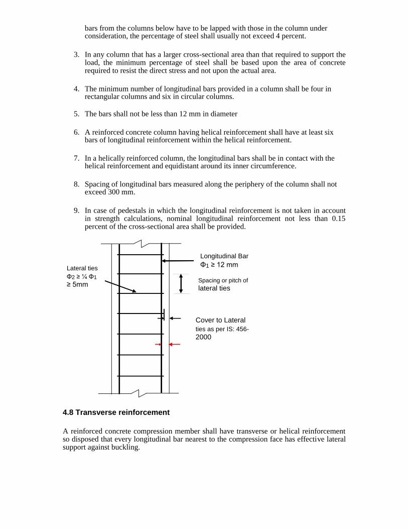
bars from the columns below have to be lapped with those in the column under consideration, the percentage of steel shall usually not exceed 4 percent.
3. In any column that has a larger cross-sectional area than that required to support the load, the minimum percentage of steel shall be based upon the area of concrete required to resist the direct stress and not upon the actual area.
4. The minimum number of longitudinal bars provided in a column shall be four in
rectangular columns and six in circular columns.
5. The bars shall not be less than 12 mm in diameter
6. A reinforced concrete column having helical reinforcement shall have at least six
bars of longitudinal reinforcement within the helical reinforcement.
7. In a helically reinforced column, the longitudinal bars shall be in contact with the
helical reinforcement and equidistant around its inner circumference.
8. Spacing of longitudinal bars measured along the periphery of the column shall not
exceed 300 mm.
9. In case of pedestals in which the longitudinal reinforcement is not taken in account
in strength calculations, nominal longitudinal reinforcement not less than 0.15 percent of the cross-sectional area shall be provided.
Lateral ties
Φ2 ≥ ¼ Φ1
≥ 5mm
Longitudinal Bar
Φ1 ≥ 12 mm Spacing or pitch of lateral ties
Cover to Lateral ties as per IS: 456- 2000
4.8 Transverse reinforcement
A reinforced concrete compression member shall have transverse or helical reinforcement so disposed that every longitudinal bar nearest to the compression face has effective lateral support against buckling.

The effective lateral support is given by transverse reinforcement either in the form of circular rings capable of taking up circumferential tension or by polygonal links (lateral ties) with internal angles not exceeding 135°. The ends of the transverse reinforcement shall be properly anchored.
Arrangement of transverse reinforcement
If the longitudinal bars are not spaced more than 75 mm on either side, transverse reinforcement need only to go round corner and alternate bars for the purpose of providing effective lateral supports (Ref. IS:456).
If the longitudinal bars spaced at a distance of not exceeding 48 times the diameter of the tie are effectively tied in two directions, additional longitudinal bars in between these bars need to be tied in one direction by open ties (Ref. IS:456).
Pitch and diameter of lateral ties
1) Pitch-The pitch of transverse reinforcement shall be not more than the least of the following distances: i) The least lateral dimension of the compression members; ii) Sixteen times the smallest diameter of the longitudinal reinforcement bar to be tied; and iii) 300 mm.
2) Diameter-The diameter of the polygonal links or lateral ties shall be not less than onefourth of the diameter of the largest longitudinal bar, and in no case less than 6 mm.
Helical reinforcement
1) Pitch-Helical reinforcement shall be of regular formation with the turns of the helix spaced evenly and its ends shall be anchored properly by providing one and a half extra turns of the

spiral bar. Where an increased load on the column on the strength of the helical reinforcement is allowed for, the pitch of helical turns shall be not more than 7.5 mm, nor more than one-sixth of the core diameter of the column, nor less than 25 mm, nor less than three times the diameter of the steel bar forming the helix.
4.9 LIMIT STATE OF COLLAPSE: COMPRESSION
Assumptions 1. The maximum compressive strain in concrete in axial compression is taken as 0.002.
2. The maximum compressive strain at the highly compressed extreme fibre in
concrete subjected to axial compression and bending and when there is no tension on the section shall be 0.0035 minus 0.75 times the strain at the least compressed extreme fibre.
In addition the following assumptions of flexure are also required
3. Plane sections normal to the axis remain plane after bending.
4. The maximum strain in concrete at the outermost compression fibre is taken as
0.0035 in bending.
5. The relationship between the compressive stress distribution in concrete and the strain in
concrete may be assumed to be rectangle, trapezoid, parabola or any other shape which results in prediction of strength in substantial agreement with the results of test.
6. An acceptable stress strain curve is given in IS:456-200. For design purposes, the compressive strength of concrete in the structure shall be assumed to be 0.67 times the characteristic strength. The partial safety factor y of 1.5 shall be applied in addition to this.
7. The tensile strength of the concrete is ignored.
8. The stresses in the reinforcement are derived from representative stress-strain curve
for the type of steel used. Typical curves are given in IS:456-2000. For design purposes the partial safety factor equal to 1.15 shall be applied.
Minimum eccentricity
As per IS:456-2000, all columns shall be designed for minimum eccentricity, equal to the unsupported length of column/ 500 plus lateral dimensions/30, subject to a minimum of 20
mm. Where bi-axial bending is considered, it is sufficient to ensure that eccentricity exceeds the minimum about one axis at a time.
Short Axially Loaded Members in Compression
The member shall be designed by considering the assumptions given in 39.1 and the minimum eccentricity. When the minimum eccentricity as per 25.4 does not exceed 0.05 times the lateral dimension, the members may be designed by the following equation:

Pu = 0.4 fck Ac + 0.67 fy Asc
Pu = axial load on the member,
fck = characteristic compressive strength of the concrete, Ac = area of concrete, fy = characteristic strength of the compression reinforcement, and As = area of longitudinal reinforcement for columns.
Compression Members with Helical Reinforcement
The strength of compression members with helical reinforcement satisfying the requirement of IS: 456 shall be taken as 1.05 times the strength of similar member with lateral ties.
The ratio of the volume of helical reinforcement to the volume of the core shall not be less than
Vhs / Vc > 0.36 (Ag/Ac – 1) fck/fy
Ag = gross area of the section,
Ac = area of the core of the helically reinforced column measured to the outside diameter of the helix, fck = characteristic compressive strength of the concrete, and fy = characteristic strength of the helical reinforcement but not exceeding 415 N/mm.
Members Subjected to Combined Axial Load and Uni-axial Bending
Use of Non-dimensional Interaction Diagrams as Design Aids
Design Charts (for Uniaxial Eccentric Compression) in SP-16
The design Charts (non-dimensional interaction curves) given in the Design Handbook, SP :
16 cover the following three cases of symmetrically arranged reinforcement :
(a) Rectangular sections with reinforcement distributed equally on two sides (Charts 27 – 38): the ‘two sides’ refer to the sides parallel to the axis of bending; there are no inner rows of
bars, and each outer row has an area of 0.5As this includes the simple 4–bar configuration.
(b) Rectangular sections with reinforcement distributed equally on four sides (Charts 39 –
50): two outer rows (with area 0.3As each) and four inner rows (with area 0.1As each) have been considered in the calculations ; however, the use of these Charts can be extended, without significant error, to cases of not less than two inner rows (with a minimum area 0.3A in each outer row).
s (c) Circular column sections (Charts 51 – 62): the Charts are applicable for circular sections
with at least six bars (of equal diameter) uniformly spaced circumferentially.
Corresponding to each of the above three cases, there are as many as 12 Charts available
covering the 3 grades of steel (Fe 250, Fe 415, Fe 500), with 4 values of d1/ D ratio for each
grade (namely 0.05, .0.10, 0.15, 0.20). For intermediate values of d1/ D, linear interpolation
may be done. Each of the 12 Charts of SP-16 covers a family of non-dimensional design
interaction curves with p/fck values ranging from 0.0 to 0.26.

From this, percentage of steel (p) can be found. Find the area of steel and provide the required number of bars with proper arrangement of steel as shown in the chart.
Typical interaction curve
Salient Points on the Interaction Curve
The salient points, marked 1 to 5 on the interaction curve correspond to the failure strain profiles, marked 1 to 5 in the above figure.
The point 1 in figure corresponds to the condition of axial loading with e = 0. For this case of ‘pure’ axial compression.
The point 11 in figure corresponds to the condition of axial loading with the
mandatory minimum eccentricity emin prescribed by the Code.
The point 3 in figure corresponds to the condition xu = D, i.e., e = eD. For e < eD, the
entire section is under compression and the neutral axis is located outside the section
(xu > D), with 0.002 < εcu < 0.0035. For e > eD, the NA is located within the section
(xu < D) and εcu = 0.0035 at the ‘highly compressed edge’.
The point 4 in figure corresponds to the balanced failure condition, with e = eb and xu =
xu, b . The design strength values for this ‘balanced failure’ condition are denoted as
Pub and Mub.
The point 5 in figure corresponds to a ‘pure’ bending condition (e = ∞, PuR = 0); the
resulting ultimate moment of resistance is denoted Muo and the corresponding NA
depth takes on a minimum value xu, min.

4.10 Procedure for using of Non-dimensional Interaction Diagrams as Design Aids to find steel
Given: Size of column, Grade of concrete, Grade of steel (otherwise assume suitably) Factored load and Factored moment
Assume arrangement of reinforcement: On two sides or on four sides Assume moment due to minimum eccentricity to be less than the actual moment Assume suitable axis of bending based on the given moment (xx or yy) Assuming suitable diameter of longitudinal bars and suitable nominal cover
1. Find d1/D from effective cover d
1
2. Find non dimensional parameters Pu/fckbD and Mu/fckbD2
3. Referring to appropriate chart from S-16, find p/fck and hence the percentage of reinforcement, p
4. Find steel from, As = p bD/100 5. Provide proper number and arrangement for steel 6. Design suitable transverse steel 7. Provide neat sketch
Members Subjected to Combined Axial Load and Biaxial Bending
The resistance of a member subjected to axial force and biaxial bending shall be obtained on the basis of assumptions given in IS:456 with neutral axis so chosen as to satisfy the equilibrium of load and moments about two axes. Alternatively such members may be designed by the following equation:
[Mux/Mux1]αn
+ [Muy/Muy1]αn
≤ 1, where Mux and My = moments about x and y axes due to design loads,
Mux1 and My1 = maximum uni-axial moment capacity for an axial load of Pu bending about x
and y axes respectively, and αn is related to Pu /Puz, where Puz = 0.45 fck .Ac + 0.75 fy Asc
For values of Pu /Puz = 0.2 to 0.8, the values of αn vary linearly from 1 .0 to 2.0. For values less than 0.2 and greater than 0.8, it is taken as 1 and 2 respectively
NOTE -The design of member subject to combined axial load and uniaxial bending will involve lengthy calculation by trial and error. In order to overcome these difficulties interaction diagrams may be used. These have been prepared and published by BIS in SP:16 titled Design aids for reinforced concrete to IS 456-2000.
IS:456-2000 Code Procedure
1. Given Pu, Mux, Muy, grade of concrete and steel 2. Verify that the eccentricities ex = Mux/Pu and ey = Muy/Pu are not less than the
corresponding minimum eccentricities as per IS:456-2000 3. Assume a trial section for the column (square, rectangle or circular).

4. Determine Mux1 and Muy1, corresponding to the given Pu (using appropriate curve from SP-16 design aids)
5. Ensure that Mux1 and Muy1 are significantly greater than Mux and Muy respectively; otherwise, suitably redesign the section.
6. Determine Puz and hence αn 7. Check the adequacy of the section using interaction equation. If necessary, redesign
the section and check again.
Slender Compression Members: The design of slender compression members shall be based on the forces and the moments determined from an analysis of the structure, including the effect of deflections on moments and forces. When the effects of deflections are not taken into account in the analysis, additional moment given in 39.7.1 shall be taken into account in the appropriate direction.
4.11 Design Problems
1. Determine the load carrying capacity of a column of size 300 x 400 mm reinforced with six rods of 20 mm diameter i.e, 6-#20. The grade of concrete and steel are M20 and Fe 415 respectively. Assume that the column is short.
fck = 20 MPa, fy= 415 MPa
Area of steel ASC = 6 x π x 202/4 = 6 x 314 = 1884 mm
2
Percentage of steel = 100Asc/bD = 100x1884/300x400 = 1.57 % 2
Area of concrete Ac = Ag – Asc = 300 x 400 – 1884 = 118116 mm
Pu = 0.4 fck Ac + 0.67 fy Asc
0.4x20x118116 + 0.67x415x1884 944928 + 523846 = 1468774 N = 1468. 8 kN
Therefore the safe load on the column = 1468.8 /1.5 = 979.2 kN
2. Determine the steel required to carry a load of 980kN on a rectangular column of size 300 x 400 mm. The grade of concrete and steel are M20 and Fe 415 respectively. Assume that the column is short.
fck = 20 MPa, fy= 415 MPa, P = 980 kN
Area of steel ASC = ?
Area of concrete Ac = Ag – Asc = (300 x 400 – ASC)
Ultimate load carried by the column
Pu = 0.4 fck Ac + 0.67 fy Asc
980 x 1.5 x 1000 = 0.4x20x (300 x 400 – ASC) + 0.67x415 ASC = 960000 - 8 ASC + 278.06
ASC ASC =1888.5 mm2,
Percentage of steel = 100Asc/bD = 100x1888.5 /300x400 = 1.57 % which is more than 0.8% and less than 6% and therefore ok.
Use 20 mm dia. bas, No. of bars = 1888.5/314 = 6.01 say 6

3. Design a square or circular column to carry a working load of 980kN. The grade of
concrete and steel are M20 and Fe 415 respectively. Assume that the column is short.
Let us assume 1.0% steel (1 to 2%)
Say ASC = 1.0% Ag =1/100 Ag = 0.01Ag
fck = 20 MPa, fy= 415 MPa, P = 980 kN
Area of concrete Ac = Ag – Asc = Ag -0.01Ag = 0.99 Ag
Ultimate load carried by the column
Pu = 0.4 fck Ac + 0.67 fy Asc
980 x 1.5 x 1000 = 0.4x20x 0.99 Ag + 0.67x415 x 0.01Ag = 7.92 Ag + 2.78 Ag
=10.7Ag Ag = 137383 mm2
Let us design a square column:
B = D = √ Ag =370.6 mm say 375 x 375 mm
This is ok. However this size cannot take the minimum eccentricity of 20 mm as
emin/D = 20/375 =0.053 > 0.05. To restrict the eccentricity to 20 mm, the required size is 400x 400 mm.
Area of steel required is Ag = 1373.8 mm2. Provide 4 bar of 22 mm diameter. Steel
provided is 380 x 4 = 1520 mm2
Actual percentage of steel = 100Asc/bD = 100x1520 /400x400 = 0.95 % which is more than 0.8% and less than 6% and therefore ok.
Design of Transverse steel:
Diameter of tie = ¼ diameter of main steel = 22/4 =5.5mm or 6 mm, whichever is greater. Provide 6 mm.
Spacing: < 300 mm, < 16 x22 = 352mm, < LLD = 400mm. Say 300mm c/c
Design of circular column:
Here Ag = 137383 mm2
π x D2/4 = Ag, D= 418.2 mm say 420 mm. This satisfy the minimum eccentricity of
20m Also provide 7 bars of 16 mm, 7 x 201 = 1407 mm2
Design of Transverse steel:
Dia of tie = ¼ dia of main steel = 16/4 = 4 mm or 6 mm, whichever is greater. Provide 6 mm.
Spacing: < 300 mm, < 16 x16 = 256 mm, < LLD = 420mm. Say 250 mm c/c
4. Design a rectangular column to carry an ultimate load of 2500kN. The unsupported length
of the column is 3m. The ends of the column are effectively held in position

and also restrained against rotation. The grade of concrete and steel are M20 and Fe
415 respectively.
Given:
fck = 20 MPa, fy= 415 MPa, Pu = 2500kN
Let us assume 1.0% steel (1 to 2%)
Say ASC = 1.0% Ag =1/100 Ag = 0.01Ag
Area of concrete Ac = Ag – Asc = Ag -0.01Ag = 0.99 Ag
Ultimate load carried by the column
Pu = 0.4 fck Ac + 0.67 fy Asc
2500 x 1000 = 0.4x20x 0.99 Ag + 0.67x415 x 0.01Ag = 7.92 Ag + 2.78 Ag
=10.7Ag Ag = 233645 mm2
If it is a square column:
B = D = √ Ag =483 mm. However provide rectangular column of size 425 x 550mm.
The area provided=333750 mm2
Area of steel = 2336 mm2, Also provide 8 bars of 20 mm, 6 x 314 = 2512 mm
2
Check for shortness: Ends are fixed. lex = ley = 0.65 l = 0.65 x 3000 = 1950 mm
lex /D= 1950/550 < 12, and ley /b = 1950/425 < 12, Column is short
Check for minimum eccentricity:
In the direction of longer direction
emin, x = lux/500 + D/30 = 3000/500 + 550/30 = 24.22mm or 20mm whichever is greater.
emin, x = 24.22 mm < 0.05D = 0.05 x 550 =27.5 mm. O.K
In the direction of shorter direction
emin, y= luy/500 + b/30 = 3000/500 + 425/30 = 20.17 mm or 20mm whichever is greater.
emin, x = 20.17 mm < 0.05b = 0.05 x 425 =21.25 mm. O.K
Design of Transverse steel:
Dia of tie = ¼ dia of main steel = 20/4 = 5 mm or 6 mm, whichever is greater. Provide 6 mm or 8 mm.
Spacing: < 300 mm, < 16 x20 = 320 mm, < LLD = 425mm. Say 300 mm c/c

5. Design a circular column with ties to carry an ultimate load of 2500kN. The unsupported length of the column is 3m. The ends of the column are effectively held in position but not against rotation. The grade of concrete and steel are M20 and Fe 415 respectively.
Given:
fck = 20 MPa, fy= 415 MPa, Pu = 2500kN
Let us assume 1.0% steel (1 to 2%)
Say ASC = 1.0% Ag =1/100 Ag = 0.01Ag
Area of concrete Ac = Ag – Asc = Ag -0.01Ag = 0.99 Ag
Ultimate load carried by the column
Pu = 0.4 fck Ac + 0.67 fy Asc
2500 x 1000 = 0.4x20x 0.99 Ag + 0.67x415 x 0.01Ag = 7.92 Ag + 2.78 Ag
=10.7Ag Ag = 233645 mm2
π x D2/4 = Ag, D = 545.4 mm say 550 mm.
Area of steel = 2336 mm2, Also provide 8 bars of 20 mm, 6 x 314 = 2512 mm
2
Check for shortness: Ends are hinged lex = ley = l = 3000 mm
lex /D= 3000/550 < 12, and ley /b = 3000/425 < 12, Column is short
Check for minimum eccentricity:
Here, emin, x = emin, y = lux/500 + D/30 = 3000/500 + 550/30 = 24.22mm or 20mm whichever is greater.
emin = 24.22 mm < 0.05D = 0.05 x 550 =27.5 mm. O.K
Design of Transverse steel:
Diameter of tie = ¼ dia of main steel = 20/4 = 5 mm or 6 mm, whichever is greater. Provide 6 mm or 8 mm.
Spacing: < 300 mm, < 16 x20 = 320 mm, < LLD = 550mm. Say 300 mm c/c
Similarly square column can be designed.
If the size of the column provided is less than that provided above, then the minimum eccentricity criteria are not satisfied. Then emin is more and the column is to be designed as

uni axial bending case or bi axial bending case as the case may be. This situation arises when more steel is provided ( say 2% in this case).
Try to solve these problems by using SP 16 charts, though not mentioned in the syllabus.
6. Design the reinforcement in a column of size 450 mm × 600 mm, subject to an axial load of 2000 kN under service dead and live loads. The column has an unsupported length of 3.0m and its ends are held in position but not in direction. Use M 20 concrete and Fe 415 steel.
Solution:
Given: lu= 3000 mm, b = 450 mm, D = 600 mm, P =2000kN, M20, Fe415
Check for shortness: Ends are fixed. lex = ley = l = 3000 mm
lex /D= 3000/600 < 12, and ley /b = 3000/450< 12, Column is short
Check for minimum eccentricity:
In the direction of longer direction
emin, x = lux/500 + D/30 = 3000/500 + 600/30 = 26 mm or 20mm whichever is
greater. emin, x = 26 mm < 0.05D = 0.05 x 600 =30 mm. O.K
In the direction of shorter direction
emin, y= luy/500 + b/30 = 3000/500 + 450/30 = 21 mm or 20mm whichever is
greater. emin, x = 21 mm < 0.05b = 0.05 x 450 =22.5 mm. O.K
Minimum eccentricities are within the limits and hence code formula for axially loaded short columns can be used.
Factored Load
P = service load × partial load factor u
= 2000 × 1.5 = 3000 kN
Design of Longitudinal Reinforcement
Pu = 0.4 fck Ac + 0.67 fy Asc or
Pu = 0.4 fck Ac + (0.67 fy - 0.4fck) Asc
3
3000 × 10 = 0.4 × 20 × (450 × 600) + (0.67 × 415–0.4 × 20)Asc 3
= 2160×10 + 270.05Asc

3
2
⇒ Asc = (3000–2160) × 10 /270.05 = 3111 mm
In view of the column dimensions (450 mm, 600 mm), it is necessary to place intermediate bars, in addition to the 4 corner bars:
2
Provide 4–25φ at corners ie, 4 × 491 = 1964 mm 2
and 4–20φ additional ie, 4 × 314 = 1256 mm 2 2
⇒ Asc = 3220 mm > 3111 mm
⇒ p = (100×3220) / (450×600) = 1.192 > 0.8 (minimum steel), OK.
Design of transverse steel
Diameter of tie = ¼ diameter of main steel = 25/4 =6.25 mm or 6 mm, whichever is greater. Provide 6 mm.
Spacing: < 300 mm, < 16 x 20 = 320 mm, < LLD = 450mm. Say 300 mm c/c Thus provide ties 8mm @ 300 mm c/c
Sketch:
Example: Square Column with Uniaxial Bending

LSM: DESIGN OF FOOTING
Most of the structures built by us are made of reinforced concrete. Here, the part of the structure
above ground level is called as the superstructure, where the part of the structure below the ground
level is called as the substructure. Footings are located below the ground level and are also referred
as foundations. Foundation is that part of the structure which is in direct contact with soil. The R.C.
structures consist of various structural components which act together to resist the applied loads and
transfer them safely to soil. In general the loads applied on slabs in buildings are transferred to soil
through beams, columns and footings. Footings are that part of the structure which are generally
located below ground Level. They are also referred as foundations. Footings transfer the vertical
loads, Horizontal loads, Moments, and other forces to the soil.
The important purpose of foundation are as follows;
1. To transfer forces from superstructure to firm soil below.
2. To distribute stresses evenly on foundation soil such that foundation soil neither fails nor experiences excessive settlement.
3. To develop an anchor for stability against overturning.
4. To provide an even surface for smooth construction of superstructure.
Due to the loads and soil pressure, footings develop Bending moments and Shear forces.
Calculations are made as per the guidelines suggested in IS 456 2000 to resist the internal forces.
5.2. Types of Foundations
Based on the position with respect to ground level, Footings are classified into two types; 1. Shallow Foundations 2. Deep Foundations
Shallow Foundations are provided when adequate SBC is available at relatively short
depth below ground level. Here, the ratio of Df / B < 1, where Df is the depth of footing and
B is the width of footing. Deep Foundations are provided when adequate SBC is available
at large depth below ground level. Here the ratio of Df / B >= 1.
5.2.1 Types of Shallow Foundations
The different types of shallow foundations are as follows:
Isolated Footing Combined footing Strap Footing Strip Footing Mat/Raft Foundation Wall footing

Some of the popular types of shallo w foundations are briefly discussed below.
a) Isolated Column Footing
These are independent footings wh ich are provided for each column. This type of footing is chosen when
SBC is generally high Columns are far apart Loads on footings are less
The isolated footings can have diffe rent shapes in plan. Generally it depends on the shape of column cross section Some of the popular s hapes of footings are;
Square Rectangular Circular
The isolated footings essentially co nsists of bottom slab. These bottom Slabs can be ei
ther flat, stepped or sloping in nature. The bottom of the slab is reinforced with steel
mesh to r esist the two internal forces namely bending moment and shear force.
The sketch of a typical isolated foot ing is shown in Fig. 1.
Fig. 1 Plan and section of typical isolated footing
b) Combined Column Footing
These are common footings which support the loads from 2 or more columns. Combined footings are provided when
SBC is generally less Columns are closely spaced Footings are heavily loaded
In the above situations, the area required to provide isolated footings for the colu mns generally
overlap. Hence, it is advantageous to provide single combined footing. In some case s the columns
are located on or close to property line. In such cases footings cannot be extende d on one side.
Here, the footings of exterior and i nterior columns are connected by the combined foo ting.
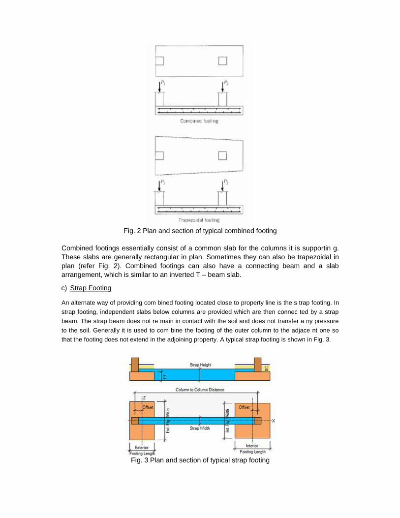
Fig. 2 Plan and section of typical combined footing
Combined footings essentially consist of a common slab for the columns it is supportin g.
These slabs are generally rectangular in plan. Sometimes they can also be trapezoidal in
plan (refer Fig. 2). Combined footings can also have a connecting beam and a slab
arrangement, which is similar to an inverted T – beam slab.
c) Strap Footing
An alternate way of providing com bined footing located close to property line is the s trap footing. In
strap footing, independent slabs below columns are provided which are then connec ted by a strap
beam. The strap beam does not re main in contact with the soil and does not transfer a ny pressure
to the soil. Generally it is used to com bine the footing of the outer column to the adjace nt one so
that the footing does not extend in the adjoining property. A typical strap footing is shown in Fig. 3.
Fig. 3 Plan and section of typical strap footing

LSM: DESIGN OF FOOTING


UNIT 3
DESIGN OF FLAT SLAB
3. Interior panel
4. Exterior panel
Various components of flat slab:
• Without drop and head
• With drop and without head
• With drop and head
Column strip : It is the design strip having a width of l2/4, where l2 is the span transverse to
l1. l2 – longer span, moment is considered along the span l1 Middle strip : It is the design strip bounded by a column strip on its opposite sides
Proportioning of flat slabs:
As per cl.31 of IS456-2000, the span by depth ratio of two way slab is applicable for flat
slabs and the values can be (l/d)modified by 0.9 for flat slabs with drops. Take l/d as 32
for HYSD bars As per ACI – The drop thickness should not be less than 100mm or (Thickness of slab)/4.
While calculating span by depth ratio, longer span is used.
The thickness of slab should not be less than 125mm.
The purpose of column drop is to reduce the shear stress and also reduce the
reinforcement in the column strip. The increase in column diameter at the head flaring of column head takes care of
punching shear developed at a distance of d/2 all around the junction between the slab
and column head.
Two methods of design are available for flat slabs:
b) Direct design method
c) Equivalent frame method
Direct design method: (Cl.31.4.1, IS456-2000)
Requirements for direct design methods are,
• There must be atleast three continuous spans in each direction
• The panels should be rectangular with ly/lx = l2/l1 ratio < 2

• The columns must not offset by more than 10% of the span from either of the
successive columns
• Successive span length in each direction must not differ by more than one third of
longer span.
• Design live load must not exceed 3 times the designed dead load
Design procedure:
As per Cl.31.4.2.2, IS456-2000, the total moment for a span bounded by columns
laterally is Mo = Wlo/2, where Mo is the sum of positive and negative moment in each
direction. W is the total design load covered on an area L2L1
W = w x L2 x Ln
This moment is distributed for the column strip and middle strip
Moment distribution for Interior Panel:
Column strip Middle strip
Negative moment (65%) 65 x 0.75 = 49% 65 x 0.2 = 15%
Positive moment (35%) 35 x 0.6 = 21% 35 x 0.4= 15%
Mo = WL
8o
Also Lo should not be less than 0.65 times of L1 [Ln > 0.65L1)
c) Design a flat slab system (interior panel) to suit the following
data: Size of the floor = 20 x 30m
Column interval = 5m c/c
Live load on slab = 5kN/m2
Materials used are Fe415 HYSD bars and M20 concrete
_________________________________________________________________________________________________________________________

Proportioning of flat slab:
Assume l/d as 32, d = 5000/32 d = 156.25mm
d = 175mm (assume), D = 175 + 20 + 10/2 = 200mm
As per ACI code, the thickness of drop > 100mm and > (Thickness of slab)/4
Therefore, 100mm or 200/4=50mm
Provide a column drop of 100mm
Overall depth of slab at drop = 200 + 100 =
300mm Length of the drop > L/3 = 5/3 = 1.67m Provide length of drop as 2.5m. For the panel, 1.25m is the contribution of drop.
Column head = L/4 = 5/4 = 1.25m
L1 = L2 = 5m
Ln = L2 – D = 5 – 1.25 = 3.75m
As per code, Mo = WLo
8
_________________________________________________________________________________________________________________________

Loading on slab: (Average thickness = (300 + 200)/2 = 250mm)
Self weight of slab = 25 x 0.25 = 6.25 kN/m2
Live load = 5 kN/m2
Floor finish = 0.75 kN/m2
Total = 12 kN/m2
Factored load = 1.5 x 12 = 18 kN/m2
W = wu x L2 x Ln = 18 x 5 x 3.75 = 337.5 kN
Total moment on slab panel = (337.5 x 3.75)/8 = 158.203 kNm
Distribution of moment:
Column strip Middle strip
Negative moment (65%) 65 x 0.75 = 49% 65 x 0.2 = 15%
0.49 x 158.2 = 77.52kNm 0.15 x 158.2 = 23.73kNm
Positive moment (35%) 35 x 0.6 = 21% 35 x 0.4= 15%
0.21 x 158.2 = 33.22 kNm 0.15 x 158.2 = 23.73kNm
Check for depth adopted:
Column strip:
Mu = 0.138.fck.b.d2 b = 2.5m 77.5 x 10
6 = 0.138
x 20 x 2.5 x 1000 x d2
d = 105.98mm ~ 106mm <
275mm Middle strip:
Mu = 0.138.fck.b.d2 b = 2.5m 23.73 x 10
6 = 0.138
x 20 x 2.5 x 1000 x d2
d = 58.68mm ~ 59mm < 175mm
Check for punching shear:
The slab is checked for punching shear
at a distance of d/2 all around the face
of the column head. The load on the
slab panel excluding the circular area of
diameter (D + d) is the punching shear
force.
_________________________________________________________________________________________________________________________

Shear force = Total Load – (Load on circular area)
= 18 x 5 x 5 – (π(D + d)2/4) x wn
= 417.12 kN
Shear force along the perimeter of the circular area = ShearForce
= 87.06 kN (D d )
Nominal shear stress: (b = 1m)
ςv = V
u = 87.06x103 = 0.317 N/mm2
b.D 1000x275
Design shear stress: ςc = K.ςc’
Where, K = (0.5 + β) ≤ 1
= 1.5 ≤ 1
ςc’ = 0.25. fck = 1.118 N/mm2
ςc = 1 x 1.118 = 1.118 N/mm2
ςv < ςc
Safe in shear.
Reinforcement:
Column strip: (b=2.5m), (d = 275mm)
Negative moment = 77.5 x 10⁶ Nmm
M 0.87. f .A . d 0.42 0.87. f y Ast [OR] K = M u Take ptfrom SP16 u y
st
0.36. fck .b
bd 2
77.6 x 106 = 99.29 x 10
3.Ast – 3.04.Ast
2
Ast = 800.16 mm2 Required
10mm @ 240mm c/c
Min Ast: 0.12% of c/s = 0.12/100 x 1000 x 275 = 825
mm2 Provide 10mm @ 230mm c/c
Positive moment = 33.2 kNm
Ast = 337.876 mm2
Provide 8mm @ 370mm c/c
Min. steel: Provide 10mm @ 230mm c/c
Middle strip: (b = 2.5m), (d = 175mm)
Negative and positive moment: 23.7 kNm
Ast = 382.6 mm2
Ast min. = (0.12/100 x 1000 x 2500 x 175) = 525 mm2
_________________________________________________________________________________________________________________________

Provide 8mm @ 230mm c/c.
_________________________________________________________________________________________________________________________

FLAT SLAB [EXTERIOR PANEL] (Cl31.4.3.3, IS456-2000)
Stiffness of slab and column = 4EI
, where, I = bd3/12 (or) πd
4/64, E = 5000
f
ck L
αc is checked with αc min given in Table 17 of IS456. From Cl.31.4.3.3, the interior and
exterior negative moments and the positive moments are found.
Interior negative design moment is,
0.75
0.10
where, αc =
Kc
1 1 K s
c
Interior positive design moment is,
0.63 0.28
1 1
c
Exterior negative design moment is,
0.65
1 1
c
The distribution of interior negative moment for column strip and middle strip is in the ratio
3:1 (0.75 : 0.25) The exterior negative moment is fully taken by the column strip. The distribution of positive
moment in column strip and middle strip is in the ratio 1.5 : 1 (0.6 : 0.4).
Design an exterior panel of a flat slab floor system of size 24m x 24m, divided into panels
6m x 6m size. The live load on the slab is 5 kN/m2 and the columns at top and bottom are
at diameter 400mm. Height of each storey is 3m. Use M20 concrete and Fe415 steel.
l/d = 32 d = 6000/32 = 187.5 mm
Length of drop ≥ 3m
Length of drop = Column strip = 3m
Assume effective depth, d = 175mm, D = 200mm
As per ACI, Assume a drop of 100mm
Depth of slab at the drop is 300mm
Diameter of column head = l/4 = 6/4 = 1.5m
_________________________________________________________________________________________________________________________

s
Loading on slab:
Self weight of slab = (0.2 + 0.3)/2 x 25 = 0.25 x 25 = 6.25 kN/m2
Live load = 5 kN/m2
Floor finish = 0.75 kN/m2
Total = 12 kN/m2
Factored load = 1.5 x 12 = 18 kN/m2
To find the value of αc =
Kc
K s
as per Cl.3.4.6.,
αc = flexural stiffness of column and slab
ΣKc = summation of flexural stiffness of columns above and
below ΣKs = summation of flexural stiffness of slab
ΣKc = 2 4EI
= 2 4xExIc
= 2x4x22.3606x103 x1.25x109
L
Lc
3000
Where, I = πd4/64 = π x 400
4 /64, E = 5000
= 22.3606 x 10³ f
ck
4xEx6000x(250) 3 6
ΣKs =
= 5.208 x 10 E
12x6000
αc = 0.644
From Table 17 of IS456-2000
αc min = L2/L1 = 6/6 = 1
LL / DL =
5
= 0.71 ~ 1
(6.25 0.75)
αc min = 0.7
αc min should be < αc min
αc = 0.7
Total moment on slab = W.Ln = 273.375 kNm
8
W = wu x L2 x Ln = 18 x 6 x 4.5 = 486 kN
Ln = 6 – 1.5 = 4.5m
As per Cl.31.4.3.3 of IS456-2000,
Exterior negative design moment is,
_________________________________________________________________________________________________________________________

0.65 x Mo = 73.168 kNm where, αc = 0.7
1 1
c
Interior negative design moment is,
0.75 0.10
x Mo where, αc = Kc
1 1
K s
c
= 193.775 kNm
For column strip (75%),
= 0.75 x 193.775 = 145.3309
kNm For middle strip (25%),
= 0.25 x 193.775 = 48.44 kNm
Interior positive design moment is,
0.63 0.28
x Mo
1 1
c
= 140.708 kNm
For column strip (60%),
= 0.6 x 140.708 = 84.43
kNm For middle strip (40%),
= 0.4 x 140.708 = 56.28
kNm Check for depth:
Mulim = 0.138 fck.b.d2
145.331 x 106 = 0.138 x 20 x 3 x d2
dcs = 132.484 mm < 275 mm
Mms = 82.4 kNm
dms= 82.4 mm < 175 mm
Check for punching shear:
SF = TL – (Load on circular area)
= 18 x 6 x 6 – [π(1.775)2/4] x 18 [wn = 18]
= 648 – 44.54 = 603.45 kN [D + d = 1.5 + 0.275 = 1.775m]
Shear force/m along the perimeter of the circular area =
SF
= 108.216 kN/m (D d )
_________________________________________________________________________________________________________________________

Nominal shear stress = ςv =
Vu
= 108.216x10 3 = 0.394 N/mm2
b.d
1000x275
Design shear stress: ςc = K.ςc’‘
where, K = (0.5 + β) ≤ 1
= (0.5 + 6/6) ≤ 1
= 1.5 ≤ 1 K = 1
ς ’ = 0.25
= 1.118 N/mm2
f ck
c ςv < ςc
Section is safe in shear.
Ast for exterior negative moment (73.168 kNm), b = 3000mm, d = 275mm,
M 0.87. f .A . d 0.42 0.87. f y Ast [OR] K = M u Take ptfrom SP16
u y
st
0.36. fck .b
bd 2
73.168 x 106 = 99.28 x 10
3.Ast – 2.53.Ast
2
Ast = 751.373 mm2
Required 10mm @ 310mm c/c
Min Ast: 0.12% of c/s = 0.12/100 x 3000 x 275 = 990
mm2 Provide 10mm @ 230mm c/c
Similarly the reinforcement required in CS and MS for –ve and +ve moments are found
and listed below:
Location Ast Req. Min. Ast Ast Provided Rein. Provided
Ext. –ve Mom. CS 751 990 990 10 @ 230 c/c
Int. –ve Mom. CS 1522 990 1522 10 @ 150 c/c
Int. –ve Mom. MS 791 630 791 10 @ 290 c/c
+ve Mom. CS 869 990 990 10 @ 230 c/c
+ve Mom. MS 925 630 925 10 @ 250 c/c
_________________________________________________________________________________________________________________________


UNIT 3 FUNCTIONAL DETAILS OF TALL BUILDINGS
FACTORS AFFECTING GROWTH, HEIGHT AND STRUCTUAL FORM


GENERAL PRINCIPLES A structural engineer should choose the most efficient structural elements to resist gravity and lateral (wind and seismic) loadings. However, ideal design conditions are rarely present. The structural engineer must accommodate the following restrictions to the most efficient design: a) the architect’s internal planning of space, b) the materials selected, c) the methods of construction common to the area, d) the architect’s choice of external cladding and decorations, e) the restrictions of the site, f) the locations of MEP (HVAC, electrical and plumbing) systems, g) the magnitude of the expected horizontal loads, and h) the proportions and height determined by owner and architectural preferences. The efficiency of the structural systems are compared via their weight per unit floor area. The floor framing is a gravity load dependent only on spans and not on height (see the next slide). The weight of the columns is also a gravity load, linearly proportional to the building height. Finally, the weight of the structure used to resist horizontal loads (wind and seismic) is at least a quadratic function of load, highly dependent on height. MEASURES OF STRUCTURAL EFFICIENCY
Tall building acts simplistically as a cantilevered beam with the foundations fixed to the earth. From this model, it is evident that the typical cross-section of a building shown at left in (a) with interior and exterior columns, is not as stiff as a building where all the same columns have been moved to the perimeter of the “box” as shown at left in (b). This bending efficiency is described via a new parameter called the Bending Rigidity Index (BRI). In order to compare the bending efficiency of different floor plans, the highest BRI = 100 is given to (a) at the right for a square with four corner columns. The BRI is the total moment of inertia of all the building columns about the centroidal axes. The Empire State Building used all its columns, interior and exterior, to resist lateral loads. That arrangement is shown in (b) at right, with an array of regular bays. Its BRI = 33, which means that the structure is only 33% efficient.

Modern buildings have closely spaced exterior columns and clear spans to the elevator core, thus forming a “tube”. The first use of this method was the World Trade Center (c), whereas the Sears (d) was formed from 9 “bundled” tubes, shown in (d). Citicorp Tower is shown in (e) did not use its corners, and its BRI dropped to 31%. The same columns move to the corner (f) would produce a BRI of 56%. The Bank of South West Tower in Houston, shown in (g) increased its BRI = 63%.
In order for columns to work as elements of an integrated system, they must interconnect to form an effective shear-resisting system, represented by the Shear Rigidity Index (SRI). An ideal SRI = 100 is shown in (a) with solid walls without openings. The diagonal-web system in (b) with 45° angles has SRI=62.5. The common bracing in (c) that combines diagonals with horizontal girders has SRI = 31.3. The modern shear systems that employ the rigidly joined frames shown in (d thru g) have higher SRIs, depending on the proportions of the member’s lengths and depths. When all four faces have these frames, they form “tubes”, which is presently most advanced structural system. FUNCTION VERSUS STRUCTURAL FORM. Office Plans Residential Plans

Office spaces should be large and open, with as many external views are possible, to be subdivided with lightweight partitions in order to satisfy different tenant leasing. The main vertical elements are placed around the perimeter. Services are distributed horizontally within the ceiling space. Thus, office story heights are typically 11’- 6” (3.5 m) or more. Therefore, a typical 40 story office building will have an approximate height of 460 feet. Residential and hotel spaces have permanent subdivisions. Continuous vertical elements can thus be hidden within the partitions. The services also run vertically hidden within the partitions to emerge where required. Ceiling spaces are thus not required except in corridors. Typical story heights are 8’-8” (2.7 m) or more. Therefore, a typical 40 story residential building will have an approximate height of 350 feet, or 80% of the height of an office building with the same number of floors. Structural Concepts
Measures of Structural Efficiency: 1. The bending rigidity index (BRI) 2. The shear rigidity index (SRI)
Structural Forms: 1. Rigid frames, 2. Braced frames, 3. In-filled frames, 4. Shear walls, 5. Wall frame, 6. Framed tube, 7. Outrigger braced, 8. Suspended, 9. Core structures, 10. Space structures, and 11. Hybrid structures. STRUCTURAL FORMS:
Simple Frames. Example: Miami’s Stiltsville in Biscayne Bay is an example of an extremely simply framed structure.
1. RIGID FRAMES Rigid frames connect the columns and girders via moment-resistant connections. The lateral stiffness of a rigid frame depends on the bending stiffness of the columns, girders and connections to the frame. A major advantage of the rigid frame is the open rectangular spaces which allow greater planning for windows and

doors. Rigid frames typically frame 20 ft to 30 ft bays. When used as the sole lateral load resisting system, rigid frames are economical only to 25 stories. Above that height they are too flexible. Increasing the member sizes would call for uneconomical solutions. Rigid frames are ideal for reinforced concrete, because of the inherent rigidity of the joints. Steel frames are more costly to stiffen the moment-resistant connections. The size of the columns and girders at any level are directly as function of the external shear at that level. Therefore, they increase in size towards the base. Floor designs are not repetitive as in braced frames. Ceiling height also increase towards the base because of the larger girders, so story heights vary.
The Home Insurance Building: The first metal framed building in the world was the Home Insurance Building. As such, it became the world’s first “second generation” structural building. It was built in Chicago in 1885. Chicago was a natural birthplace for this new structural paradigm because it was the center for the US’s rail network, and of course, railroads meant steel (although this building used wrought iron). The Woolworth Building (NewYork City): Finished in 1913, this 60 story structure was the “first” skyscraper, the term was coined for this building in particular. It is a steel rigid frame form, that relies on its interior masonry walls to provide lateral resistance to winds. THE TRADITIONAL RIGID FRAME The rigid frame was a wonderful paradigm shift in structural thinking that was born in 1885 with the use of steel and has become the main product of the second generation of structures. The problem with this now traditional structural form is that the frame becomes increasingly cluttered, especially the core areas, where elevators, stairs and the building’s services inhibit the economic and aesthetic use of space.
The Empire State Building (New York). The Empire State is also a rigid frame that became the world’s tallest building in 1931, two weeks before the Great Depression. Its basic structural form is a steel frame encased in cinder concrete.

The 70,000 tons of structural steel frame was erected in only 23 weeks. It required 44 psf of structure versus the WTC’s required 11 psf. During the Depression two major buildings became the center of a personal competition between Walter Chrysler (who built the Chrysler Building) and John Jakob (who built the Empire State Building). They each wanted to build the World’s tallest building. The Empire State Building is again the tallest building in the City of New York following thedestruction of the WTC, with observatories located on the 86th floor and 102nd floor. Construction began on March 17, 1930. The foundations are placed 55 feet below the ground surface at 33rd Street into the Manhattan Shiest bedrock. Construction began on March 17, 1930. By October 3, 1930, there were 88 floors finished and 14 to go. Concrete and steel foundation of ESB goes 55 ft below ground into Manhattan bedrock. It has a drift of 1.5 feet. Bank of America building in San Francisco. Although it was a rigid frame structure, the building was set in a high seismic zone. Hence, the conservative shape. Another example is Typical Florida RC frame for a 12-story luxury hotel in Marco Island, with 103 units. RIGID FRAME BEHAVIOUR The horizontal stiffness of a rigid frame is governed mainly by the bending resistance of the girders, the columns and their connections and in a tall frame, by the axial rigidity of the columns. The accumulated horizontal shear above any story of a rigid frame is resisted by the shear in the columns of that story. The shear causes the story-height columns to bend in double curvature with points of contraflexture at approximately mid-story height levels. The moments applied to a joint from the columns above and below are resisted by the attached girders, which also bend in double curvature, with points of contraflexture at approximately mid-span. These deformations of the columns and girders allow racking of the frame and horizontal deflection in each story. The overall deflected shape of a rigid frame structure due to racking has a shear configuration with concavity upwind, a maximum inclination near the base and a minimum inclination at the top. The overall moment of the external horizontal load is resisted in each story level by the couple resulting from the axial tensile and compressive forces in the columns on opposite sides of the structure. The extension and shortening of the columns cause overall bending and associated horizontal displacements of the structure. Because of the cumulative rotation up the height, the story drift due to overall bending increases with height, while that due to racking tends to decrease. Consequently the contribution to story drift from overall bending may in the uppermost stories, exceed that from racking. Therefore the overall deflected shape of a high-rise rigid frame usually has a shear configuration. APPROXIMATE DETERMINATION OF MEMBER FORCES CAUSED BY GRAVITY LOADING A rigid frame is a highly redundant structure and an accurate analysis can be made only after the member sizes are assigned. Therefore, member sizes are decided on the basis of approximate forces estimated either by conservative formulas or by simplified methods of analysis that are independent of member properties. Two approaches for estimating girder forces due to gravity loading are given below. 1. Girder forces – Code recommended values In rigid frames with two or more spans in which the longer of any two adjacent spans does not exceed the shorter by more than 20%, and where the uniformly distributed design live load does not exceed three times the dead load, the girder moment and shears may be estimated from table below.
Location on Girder Value of moment
Sagging moment
End spans; discontinuous end unrestrained wL2/11
End spans; discontinuous end integral with support wL2/14

Interior spans wL2/16
Hogging moment
At exterior face of first interior support; for two spans wL2/9
At exterior face of first interior support; for more than two spans wL2/10
At other faces of interior supports wL2/11
At face of all supports where, at each end of span ∑column stiffnesses/ beam stiffnesses>8
wL2/12
At interior face of exterior support for member built integrally with spandrel beam or girder
wL2/24
At interior face of exterior support for member built integrally with column wL2/16
Shear
In end members at face of first interior support 1.15wL/2
At face of all other supports wL/2
2. Girder forces – Two-Cycle moment distribution This is a concise form of moment distribution for estimating girder moments in a continuous multi-bay span. It is more accurate than the formulas in Table given above., especially for cases of unequal spans and unequal loadings in different spans. The assumptions are made here.
a) A counterclockwise restraining moment on the end of a girder is positive and a clockwise moment is negative.
b) The ends of the columns at the floors above and below the considered girder are fixed. c) In the absence of known member sizes, distribution factors at each joint are taken equal to 1/n,
where n is the number of members framing into the joint in the plane of the frame. 3. Column Forces The gravity load axial force in a column is estimated from the accumulated tributary daed and live floor loading above that level, with reductions in live load as permitted by the local code of practice. The gavity load maximum column moment is estimated by taking the maximum difference of the end moments in the connected girders and allocating it equally between the column ends just above and below the joint. To this should be added any unbalanced moment due to eccentricity of the girder connections from the centroid of the column, also allocated equally between the column ends above and below the joint.
APPROXIMATE ANALYSIS OF MEMBER FORCES CAUSED BY HORIZONTAL LOADING Allocation of loading between bents A first step in the approximate analysis of a rigid frame is to estimate the allocation of the external horizontal force to each bent. For this it is usual to assume that the floor slabs are rigid in plane and , therefore, constrain the horizontal displacements of all the vertical bents at a floor level to be related by the horizontal translations and rotation of the floor slab. Figure Symmetric plan structures subjected to symmetric loading: A symmetric structure subjected to symmetric loading translates but does not twist. Shear rigisity parameter GA for level I in a bent is given by Equation In which hi = height of story i G = ∑(Ix/L) for all girders of span L across floor I of the bent C = ∑(Ic/hi) for all the columns in story I of the bent E = Modulus of elasticity

Ic and Ix = Moment of inertia of the columns and girders respectively Asymmetric plan structures: Equation Tall building frames subjected to lateral loads are statically indeterminate and exact analysis by hand calculation takes much time and effort. Using simplifying assumptions, approximate analyses of these frames yield good estimate of member forces in the frame, which can be used for checking the member sizes. The following methods can be employed for lateral load analysis of rigidly jointed frames. • The Portal method. • The Cantilever method The portal method This method is satisfactory for buildings up to 25 stories, hence is the most commonly used approximate method for analysing tall buildings. The following are the simplifying assumptions made in the portal method: 1. A point of contraflexure occurs at the centre of each beam. 2. A point of contraflexure occurs at the centre of each column. 3. The total horizontal shear at each storey is distributed between the columns of that storey in such a way that each interior column carries twice the shear carried by each exterior column.
Portal method of analysis
The above assumptions convert the indeterminate multi-storey frame to a determinate structure. The steps involved in the analysis of the frame are detailed below: 1. The horizontal shears on each level are distributed between the columns of that floor according to assumption (3). 2. The moment in each column is equal to the column shear multiplied by half the column height according to assumption (2). 3. The girder moments are determined by applying moment equilibrium equation to the joints: by noting that the sum of the girder moments at any joint equals the sum of the column moments at that joint. These calculations are easily made by starting at the upper left joint and working joint by joint across to the right end. 4. The shear in each girder is equal to its moment divided by half the girder length. This is according to assumption (1). 5. Finally, the column axial forces are determined by summing up the beam shears and other axial forces at each joint. These calculations again are easily made by working from left to right and from the top floor down.
The cantilever method This method gives good results for high-narrow buildings compared to those from the Portal method and it may be used satisfactorily for buildings of 25 to 35 storeys tall. It is not as popular as the portal method. The simplifying assumptions made in the cantilever method are: 1. A point of contraflexure occurs at the centre of each beam 2. A point of contraflexure occurs at the centre of each column.

3. The axial force in each column of a storey is proportional to the horizontal distance of the column from the centre of gravity of all the columns of the storey under consideration.
Typical frame
The steps involved in the application of this method are: 1. The centre of gravity of columns is located by taking moment of areas of all the columns and dividing by sum of the areas of columns. 2. A lateral force P acting at the top storey of building frame is shown in Figure above forces in the columns are represented by F1, F2, F3 and F4 and the columns are at a distance of x1, x2 , x3 and x4 from the centroidal axis respectively as shown in figure below.
Top storey of the frame above plane of contraflexure
By taking the moments about the centre of gravity of columns of the storey, P h - F1x1 - F2x2 - F3x3 - F4x4 = 0 The axial force in one column may be assumed as F and the axial forces of remaining columns can be expressed in terms of F using assumption (3). 3. The beam shears are determined joint by joint from the column axial forces. 4. The beam moments are determined by multiplying the shear in the beam by half the span of beam according to assumption (1). 5. The column moments are found joint by joint from the beam moments. The column shears are obtained by dividing the column moments by the half column heights using assumption (2) THE BRACED FRAME In the braced frame system, the lateral load resistance is provided by the “web” formed by the diagonal members tied to the girders. This creates a vertical truss, with the columns acting as the chords. The horizontal shear is resisted by the horizontal component of the web members. This system is highly efficient and economical in resisting lateral loads for any height of building, including the very tallest. Another advantage of the triangulated bracing is that the girders participate only minimally in the lateral loads, and thus, the floor framing remains independent of height. Diagonal bracing obstructs the internal planning such as the placement of doors or windows. For that reason, they are generally placed around stairs, elevator and service shafts.

In the past, the diagonals were coincident with the floor height. Recently however, large- scale braced frames are being used extending many stories and bays. An example is Mexico’s Torre Mayor
Torre Mayor (Mexico). The Torre Mayor is a 57 story building that rises 225 m ( 720 ft). That makes it the tallest in Latin America. It was finished in 2004 at a cost of 250 million dollars. No bracing was placed within the two center bays, except at three locations where a set of diagonals forms a diamond shape connecting the super-X systems. The dampers on the north and south faces are placed at these diamond bracing locations. This enhances the damping system’s performance by creating a damped link between the super-X systems. 3. INFILLED-FRAMES. The infilled-frame is common in Europe for buildings up to 30 stories in height. The reinforced concrete frame of columns and girders is in-filled by panels of brickwork, block-work or cast-inplace concrete. When subjected to lateral loads, the infill acts as a strut along the compression diagonal to brace the frame. The random flow of lateral loads makes the infill frame difficult to analyze. In addition, the possible removal of walls by future tenants may weaken the frame in unpredictable ways.
4. SHEAR WALLS.

Shear walls made from reinforced concrete may serve as both architectural and structural partitions, capable of carrying gravity and lateral loads. Their very high in-plane stiffness and strength make them ideal for bracing tall buildings. In a shear wall building, the shear walls are the primary lateral load resistance. Shear walls act as vertical cantilevers in the form of separate planar walls and non-planar assemblies, typically around elevator, stairs and service shafts. Shear walls are stiffer than rigid frames, and are economical to about 55 stories. The restrictions in planning when using shear walls means that they are mostly suited to hotels and residential buildings. They provide repetitive floor by floor planning, with continuous vertical walls that serve simultaneously as acoustical and fire insulation between units. When shear walls are combined with frames, the walls attract all the lateral loads, so the frame is designed only for gravity. The wall layout must be planned so that the lateral load tensile stresses are suppressed by the gravity load stresses. Shear walls behave well in seismic events because of their planned ductility.
5. WALL-FRAME STRUCTURES. The combination of shear walls and rigid frames is called a wall-frame structure. The structure is constrained to adopt a common deflected shape to both systems through the horizontal rigidity of the girders and slab. The walls and frame interact horizontally, especially at the top, to produce a stiffer and stronger structure. The combination increases the economy of height to the 65 story range, well above the range of rigid frames or shear walls alone. In a carefully “tuned” structure, the shear in the frame can be made approximately uniform over the entire height, thereby allowing the floor framing to be repetitive. Most wall-frames are reinforced concrete. However, steel buildings may use the braced frame to offer similar benefits of horizontal interaction. The braced frames behave with an overall flexural tendency to interact with the shear mode of the rigid frame.
COUPLED WALLS. Coupled wall structures are a common form of shear walls, wherein two or more walls in the same plane are connected at the floor levels by means of beams or stiff slabs. The effect is to cause the set of walls to behave in a composite centroidal axis of the walls. The consequent horizontal stiffness is very much greater than if the cantilever, bending about the common walls acted separately. Coupled shear walls are commonly used in residential buildings, with reinforced concrete elements. Some heavy steel plates have been used with steel frames, for locations where there are very large shear forces, such as at the base of elevator shafts.

6. FRAMED-TUBE STRUCTURES. The essence of the framed-tube are the four very stiff moment-resisting frames that form the “tube” around the perimeter of the building. The frames consist of closely spaced columns, typically 6 to 12 feet c-c (2 to 4 m), tied together by horizontal deep spandrel girders. This close spacing must be interrupted at street level with the use of transfer beams, or like the WTC. The outer tube carries 100% of the lateral loads, and 75 to 90% of the gravity loads. The remaining gravity load is carried by the small cluster of core columns (or shear walls). Under lateral loads, the perimeter frames aligned in the direction of loading acts as the webs of a massive tube cantilever. The other two frames, perpendicular to the loading, act as the flanges. Obviously the most efficient tube would be a square plan (WTC and Sears) or a circular plan (e.g., Petronas). This structural form is suitable for both steel and reinforced concrete, from heights of 45 to 110 stories. The highly repetitive pattern permits to attain the economies of prefabrication. This form is the most significant modern development in tall buildings, although it needs improvement, because the flanges tend to suffer from shear lag. This shear lag is due to the mid-face flange columns being less stressed than the corner columns, and therefore not contributing as fully as they could in the flange action.
The World Trade Center (New York). The south tower was completed on 23 December 1970, and the north tower in 1972. They were the first framed tubes to reach 110 stories, and thus created a new generation of structures since their creation. The first time the framed tube was tried was with the two World Trade Center towers. The tube is formed by vertical steel columns 14”x14” spaced at 22” on center. Each side was 210 feet wide. The vertical columns are tied with spandrel beams at each floor level. The Petronas Towers (Kuala Lampur) In 1988 the towers rose to 1,483 ft (452 m), or 33 ft taller than the Sears Tower in Chicago. The towers have 88 numbered levels, but in fact have 95 floors (the number “8” is a lucky number for the Chinese). The forms are RC for central core and perimeter columns, with ring beams of 11.6 ksi concrete. Each tower is a tapering cylinder with 16 columns. The Citicorp Tower (New York City).

The Citicorp building is a steel twisted tube form, which is a variation with the external hull twisted 90 degree in plan. This forces the loads to be channeled to the four main supports via exterior diagonal bracings and a huge transfer perimeter girder at the lower levels. The external diagonal bracings had been bolted instead of welded, as called for in the plans. The bolts did not have enough strength to transfer the loads laterally and down to the four main supports. He immediately notified the building’s owner, and proposed to him a plan to strengthen of the tower by welding 2-ft plates over each bolt. These repairs were done quietly in order to avoid upsetting or alarming the tenants. Before the repairs were completed, Hurricane Elsa passed very close to New York City and thus narrowly averted disaster for the Citicorp building. His honesty and integrity were recognized by the engineering community, and serves today as an example of ethical behavior to all of us who work in this challenging field.
BUNDLED-TUBE STRUCTURES. The natural evolution of the WTC’s framed tube form was the use of several tubes bundled together “like tied sticks”. A bundled group of tubes provides greater strength that a single tube (this was the symbol of Rome’s “fasces” and the US’s bundles arrows “e pluribus unum”). These bundled tubes were first tried by Fazlur Khan in Chicago, when the Sears tower was finished in 1974. The new internal webs greatly reduce the effect of shear lag in the flanges. Therefore, the column stresses are more evenly distributed than in a single tube structure. The bundled tubes thus provide a much larger lateral stiffness, albeit at the expense of internal planning.
BRACED-TUBE STRUCTURES. The efficiency of the framed tube structures can be improved by adding diagonal bracing to the faces. This results in (a) greater heights, and (b) greater spacing between the perimeter columns. The first steel bracedtube was Chicago’s 97- story John Hancock building, shown at left, finished in 1969. The structure to its right is New York’s 780 Third Avenue Building, a reinforced concrete structure finished in 1985.

The steel tube has the bracing traverse the faces of the rigid frame. In the RC, the bracing is formed by a diagonal pattern of concrete window-size panels, poured integrally with the frame. Because the diagonals of a braced tube are connected to the columns at each intersection, they virtually eliminate the effects of shear lag in both the flange and the web frames. As a result, the structure behaves under lateral loads more like a braced frame, greatly diminishing the bending in the members of the frames. Columns may have greater spacing, allowing for much greater windows than with a conventional tube.
7. OUTRIGGER-BRACED STRUCTURES. This system consists of a central braced core, which is either a braced frame or shear walls, plus horizontal cantilever “outrigger” trusses or girders that connect the core to the outer columns. When the structure is loaded horizontally, the vertical plane rotations of the core are restrained by the outriggers through tension in the windward columns and compression in the leeward columns. The effective structural depth of the building is greatly increased, thereby augmenting its lateral stiffness and reducing the lateral deflections and the moments in the core. The outriggers join the columns to the core to make the structure behave as a partly composite cantilever. The perimeter columns can also participate in the outrigger action by joining all the perimeter columns with the horizontal truss or girder around the face of the building at the outrigger level. Typically, the outrigger level is two-stories in depth and thus are usually used to harbor the building’s MEP systems. The outrigger system has been used to 70 stories in height. If the building has greater side dimensions, this form could reach much greater heights. The efficiency of this form depends on how well are the perimeter columns tied to the core through the outrigger structure. Outriggers greater than a single story high are becoming more common, because they add a much larger stiffness to the structure. However, the economic limit of outrigger height seems to be between four to five stories high. The outrigger system has been used to 70 stories in height. If the building has greater side dimensions, this form could reach much greater heights.

The AT&T Building (New York). The AT&T building was designed structurally by Leslie Robertson and Associates, based on the architectural design of Philip Johnson. The basic structural system consists of a rigid-frame steel tube at the building perimeter. Additional stiffness was added along the width of the building by means of four vertical steel trusses. At every eighth floor, two I-shaped steel plate walls, with holes cut for circulation, extend from the sides of the trusses to the exterior columns on the same column line. The steel walls act as outrigger trusses mobilizing the full width of the building in resisting lateral force. The horizontal shear at the base of the building is transferred to two giant steel plate boxes.
8. SUSPENDED STRUCTURES.
A suspended structure consists of a central core with horizontal cantilevered outrigger trusses at the roof level, from which are suspended vertical hangers of steel cables. The floor slabs are connected to these cables. This permits the ground floor to be exempt of any perimeter columns, thereby allowing an open concourse. The cables have very small cross-sectional areas compared to columns, and can be embedded around window sills. Another advantage is the casting of the floors at ground level and then raised into position. The system is limited to relatively small heights (about 10 to 15 stories) because of structural disadvantages, such as live-load floor-to-floor connection variations, and limited core dimensions. A suspended structure consists of a central core with horizontal cantilever at the roof level, from which are suspended vertical hangers of steel cables. The floor slabs are connected to these cables. This permits the ground floor to be exempt of any perimeter columns, thereby allowing an open concourse. The cables have very small cross-sectional areas compared to columns, and can be embedded around window sills. Another advantage is the casting of the floors at ground level and then raised into position. The system is limited to relatively small heights (about 10 to 15 stories) because of structural disadvantages, such as live-load floor-to-floor variations, and limited core dimensions.

CORE STRUCTURES. A single core serves to carry the entire gravity and horizontal loading. It is similar to the suspended building, provides a column-free perimeter at ground level. However, it is highly inefficient.
9. CORE OR TUBE-IN-TUBE STRUCTURES. A variant of the framed-tube form is the replacement of the inner, or core columns and walls, with another tube. Thus, the hull (or external tube) and the new core tube act jointly to resist both gravity and lateral loads. This improved form is called a tube-in-tube, or a hull-core structure. A steel building could provide a core tube made up of braced frames, whereas a reinforced concrete building would consist of an assembly of shear walls for the core. The outer framed tube (hull) and the inner core interact horizontally as the shear and flexural components of a wall-frame structure. This provides the benefit of a greatly increased lateral stiffness. The outer tube (hull) of course always dominates, because of its greater structural depth. It is presumed that this form could push the heights to an economical 120 stories. Taipei 101 (Taiwan). In 2003, the Taipei 101 building in Taiwan became the world’s tallest structure, surpassing the Petronas Towers in Kuala Lampur. This tube-in-tube form used both a truss core and a braced frame hull to attain the tallest status. Core shear wall (Jin Mao Tower, Shanghai). Another 88-stories or 1,381 ft (421 m) tower with 50- stories of offices, 36-stories of hotel space, plus 2-stories of restaurants and observation deck. The structure has a central octagon RC core linked to the exterior composite mega-columns via outrigger trusses. The flanges of the shear walls vary from 33 inches at the foundation to 18 inches at level 87, with concrete strengths varying from 5 to 7.5 ksi.

10. SPACE STRUCTURES Space frames: three-dimensioned triangulated structures, that are very distinct from previously discussed planar bents. The space frame serves the dual function of resisting gravity and lateral loads, thereby becoming one of the most efficient structural forms. Its lightweight and high efficiency permit these frames to reach the greatest heights. A notable example is Hong Kong’s 76 story Bank of China building. Space frames are usually complex to analyze, and difficult to provide proper load transfer connections between the floors and the main frame. These connections are costly and sometimes awkward. One solution is to have an inner braced core, which serves to collect the lateral loads and the inner region gravity loading, from the slabs over a number of multistory regions. At the bottom of each region, the lateral and gravity loads are transferred out to the main joints of the space frame. These structures are very pleasing aesthetically and have great appeal to architects and the general public.
Bank of China (Hong Kong). The 76-story Bank of China, was finished in 1989 and is a good example of a cross-braced space truss structure. It was designed by I.M. Pei & Partners, with the structure designed by Leslie Robertson and Assoc. The structural system for this 1,209 ft (369m) tower consists of a cross-braced space truss. The space truss supports almost the entire weight of the building while also resisting the lateral loads expected from hurricane winds. Both the lateral and gravity loads are carried to four composite columns at the corners of the building, allowing a 170 feet (52 m) clear space span at the base of the building. A fifth composite column at the center of the building begins at the 25th floor and extends to the top. The loads on this column are transferred to the corner columns at the 25th level. At the foundation level, the corner columns are 14 feet x 26 feet (4.3m x 8m). The size of the steel section of the composite columns varies, and the concrete portion gets progressively smaller as it rises, varying by more than 10 feet (3.1 m). By composing the frame elements of steel enclosed with RC eliminated the need of expensive 3-D steel connections at the corners. 11. HYBRID STRUCTURES. The modern trend in architecture, especially the so called “postmodern” building, is to create non-regularly shaped buildings. The structural engineer will find these structures do not conform to a single form. Analysis must therefore use several combinations of the previously discussed forms. The figure below for example, a tube and outrigger system superimposed on each other, or in the figure at its right, a tube system on three faces with a space frame on a faceted fourth face. The improvements in both computer hardware and software, permit us to approximate acceptable solutions to these complex structures.


UNIT 5 COMPUTER APPLICATION
Various types of elements and some difficulties working with the method will also be mentioned. To
describe various physical problems, the use of partial differential equations (PDEs) is a good option.
These PDEs can be solved with numerical methods when the system is too complicated for an
analytical solution. To solve this numerically, the (FE) method can be used. Using FE modelling, the
structure is subdivided, discretised, into a finite number of individual elements.
The behaviour of these elements, the relation between their nodal displacements and reactions, can
be specified by shape functions. By means of the shape functions and their corresponding
derivatives, all displacements, strains and stresses within an element can be calculated.
The individual elements are only interconnected by their nodes and to get the complete solution for
the entire structure all elements are assembled [29]. The amount of elements affects the result as
more elements give a more accurate result.
However, the more complex and larger the structure is, the more the computation time increases. A
few years ago, modelling entire 3D models of a complex building was not possible due to
insufficient processing power and software. The building had to be disassembled into its different
structural parts, beams, columns, plates, walls etc. and designed separately.
This made complex architectural forms difficult to design. Nowadays, with improved computational
power and software, it is possible to calculate more complex and bigger structures. However,
trusting the FE analysis blindly can have large complications and it is up to the user to verify the
result to prevent a collapse of the structure.
The more complicated the numerical model is, the more difficult it is to interpret the accuracy of the
result and maintain a global overview of the structure
Introduction to Finite Element Analysis
1.1.1 Introduction The Finite Element Method (FEM) is a numerical technique to find approximate solutions of partial
differential equations. It was originated from the need of solving complex elasticity and structural
analysis problems in Civil, Mechanical and Aerospace engineering. In a structural simulation, FEM
helps in producing stiffness and strength visualizations. It also helps to minimize materialweight and
its cost of the structures. FEM allows for detailed visualization and indicates the distribution of
stresses and strains inside the body of a structure. Many of FE software are powerful yet complex
tool meant for professional engineers with the training and education necessary to properly interpret
the results.
Several modern FEM packages include specific components such as fluid, thermal,
electromagnetic and structural working environments. FEM allows entire designs to be constructed,
refined and optimized before the design is manufactured. This powerful design tool has significantly
improved both the standard of engineering designs and the methodology of the design process in
many industrial applications. The use of FEM has significantly decreased the time to take products
from concept to the production line. One must take the advantage of the advent of faster generation

of personal computers for the analysis and design of engineering product with precision level of
accuracy.
1.1.2 Background of Finite Element Analysis The finite element analysis can be traced back to the work by Alexander Hrennikoff (1941)and
Richard Courant(1942). Hrenikoff introduced the framework method, in which a plane elastic
medium was represented as collections of bars and beams.These pioneers share one essential
characteristic: mesh discretization of a continuous domain into a set of discrete sub-domains, usually
called elements.
a) In 1950s, solution of large number of simultaneous equations became possible because of the
digitalcomputer.
b) In 1960, Ray W. Clough first published a paper using term “Finite Element Method”.
c) In 1965, First conference on “finite elements” was held.
d) In 1967, the first book on the “Finite Element Method” was published by Zienkiewicz and
Chung.
e) In the late 1960s and early 1970s, the FEM was applied to a wide variety of engineering
problems.

(i) In the 1970s, most commercial FEM software packages (ABAQUS, NASTRAN, ANSYS,
etc.) originated.Interactive FE programs on supercomputer lead to rapid growth of CAD
systems.
(ii) In the 1980s, algorithm on electromagnetic applications, fluid flow and thermal analysis were
developed with the use of FE program.
(iii) Engineers can evaluate ways to control the vibrations and extend the use of flexible,
deployablestructures in space using FE and other methods in the 1990s. Trends to solve fully
coupled solution of fluid flows with structural interactions, bio-mechanics related problems
with a higher level of accuracy were observed in this decade.
With the development of finite element method, together with tremendous increases in computing
power and convenience, today it is possible to understand structural behavior with levels of
accuracy. This was in fact the beyond of imagination before the computer age.
1.1.3 Numerical Methods
The formulation for structural analysis is generally based on the three fundamental relations:
equilibrium, constitutive and compatibility. There are two major approaches to the analysis:
Analytical and Numerical. Analytical approach which leads to closed-form solutions is effective in
case of simple geometry, boundary conditions, loadings and material properties. However, in reality,
such simple cases may not arise. As a result, various numerical methods are evolved for solving such
problems which are complex in nature. For numerical approach, the solutions will be approximate
when any of these relations are only approximately satisfied. The numerical method depends heavily
on the processing power of computers and is more applicable to structures of arbitrary size and
complexity. It is common practice to use approximate solutions of differential equations as the basis
for structural analysis. This is usually done using numerical approximation techniques. Few
numerical methods which are commonly used to solve solid and fluid mechanics problems are given
below.
(ii) Finite Difference Method
(iii) Finite Volume Method
(iv) Finite Element Method
(v) Boundary Element Method
(vi) Meshless Method
The application of finite difference method for engineering problems involves replacing the
governing differential equations and the boundary condition by suitable algebraic equations. For

example in the analysis of beam bending problem the differential equation is reduced to be solution
of algebraic equations written at every nodal point within the beam member. For example, the beam
equation can be expressed as:
d 4 w
=
q
(1.1.1) dx 4 EI
To explain the concept of finite difference method let us consider a displacement function variable
namely w = f (x)
Fig. 1.1.1 Displacement Function
Now, w = f (x + x) −f (x)
So, dw
= Lt
w =
Lt
f(x + x) - f(x) =
1 ( wi+1 - wi )
h dx x → 0 x x →0 x
Thus,
d 2 w d 1 1 1 =
w - w = w - w - w + w = w - 2w + w
dx 2 dx
h 2
h2 (
h ( i+1 i ) ( i+2 i+1i+1 i ) i+2i+1i )
(1.1.2)
(1.1.3)
d 3 w 1
( w
i+3
- wi )
= - w
i+2
- 2wi+2
+ 2wi+1
+ wi+1 dx 3 h3
1 (1.1.4)
= ( wi+3 - 3wi+2 + 3wi+1 - wi )
h3

d 4 w
= 1
( wi+4 - wi+3 - 3wi+3 + 3wi+2 + 3wi+2 - 3wi+1 - wi+1 + wi )
4 4
dx h
= 1 (
wi+4 - 4wi+3 +6wi+2 - 4wi+1 + wi ) (1.1.5) 4
h
= 1 (
wi+2 - 4wi+1 +6wi - 4wi - 1 + wi-2 )
4
h
Thus, eq. (1.1.1) can be expressed with the help of eq. (1.1.5) and can be written in finite
difference form as:
(w − 4w + 6w − 4w + w ) = q h4 (1.1.6)
i−2 i−1 i i+1 i+2 EI
Fig. 1.1.2 Finite difference equation at node i
Thus, the displacement at node i of the beam member corresponds to uniformly distributed load can
be obtained from eq. (1.1.6) with the help of boundary conditions. It may be interesting to note that,
the concept of node is used in the finite difference method. Basically, this method has an array of
grid points and is a point wise approximation, whereas, finite element method has an array of small
interconnecting sub-regions and is a piece wise approximation.
Each method has noteworthy advantages as well as limitations. However it is possible to
solve various problems by finite element method, even with highly complex geometry and loading
conditions, with the restriction that there is always some numerical errors. Therefore, effective and
reliable use of this method requires a solid understanding of its limitations.
1.1.4 Concepts of Elements and Nodes
Any continuum/domain can be divided into a number of pieces with very small dimensions. These
small pieces of finite dimension are called ‘Finite Elements’ (Fig. 1.1.3). A field quantity in each
element is allowed to have a simple spatial variation which can be described by polynomial terms.
Thus the original domain is considered as an assemblage of number of such small elements. These
elements are connected through number of joints which are called ‘Nodes’. While discretizing the
structural system, it is assumed that the elements are attached to the adjacent elements only at the
nodal points. Each element contains the material and geometrical properties. The material properties
inside an element are assumed to be constant. The elements may be 1D elements, 2D elements or 3D
elements. The physical object can be modeled by choosing appropriate element such as frame

element, plate element, shell element, solid element, etc. All elements are then assembled to obtain
the solution of the entire domain/structure under certain loading conditions. Nodes are assigned at a
certain density throughout the continuum depending on the anticipated stress levels of a particular
domain. Regions which will receive large amounts of stress variation usually have a higher node
density than those which experience little or no stress.
Fig. 1.1.3 Finite element discretization of a domain
1.1.5 Degrees of Freedom
A structure can have infinite number of displacements. Approximation with a reasonable level of
accuracy can be achieved by assuming a limited number of displacements. This finite number of
displacements is the number of degrees of freedom of the structure. For example, the truss member
will undergo only axial deformation. Therefore, the degrees of freedom of a truss member with
respect to its own coordinate system will be one at each node. If a two dimension structure is
modeled by truss elements, then the deformation with respect to structural coordinate system will be
two and therefore degrees of freedom will also become two. The degrees of freedom for various
types of element are shown in Fig. 1.1.4 for easy understanding. Here ( u , v , w) and (θx , θ y ,θz ) represent displacement and rotation respectively.

Fig. 1.1.4 Degrees of Freedom for Various Elements