use of surface deflection for pavement design and...
TRANSCRIPT

64
Use of Surface Deflection for Pavement
Design and Evaluation
A.F. STOCK and J. YU
ABSTRACT
Most current mechanistic pavement design methods are based on strain calculated at the bottom of the aspha l t layer and the top of the subgrade. Because the only part of a pavement that is reasonably accessible when construction has been completed is the surface, it is virtually impossible to verify for a design that the parameters have actually been met. The ability of the engineer to check the design will therefore be greatly enhanced if a parameter based on surface deflection can be used. The development of just such a parameter, which has been called the tangent slope, is reported. This parameter is the slope of the tangent drawn from the point of maximum deflection of the pavement to graze its surface . A sensitivity analysis is reported in which the tangent slope is compared with several other parameters based on surface deflection as well as the conventional asphalt and subgrade strains. The calibration by back analysis of the tangent slope against current practice is presented so that it can be used as a design parameter, although its principal use may be as a tool for the structural evaluation of existing pavements and for val idating designs.
Mechanistic pavement design techniques for asphalt pavements ha ve been deve l oped to a degree that permits their appl i c ation wi th a significant measure of confidence. The Fourth International Conference on the Structural Design of Asphalt Pavements (1) in 1977 was a milestone in the deve lopment of -these methods ; i t was devoted almost entirely to the pi:e sentation 0£ complete design sys t ems or s ubsystems . Alt hough mechanistic design is a reality and ha s been for some years , it i s not wide ly accepted o r applied .
One of the reasons for this is the difficulty of checking in the short term that the response of the pavement structure is as predicted. When the principles of structural design are applied to most structural problems, it is relatively easy to check a prediction of the response of the structure against a measured response. Deformation at preselected points is usually a convenient parameter. Mechanistic design of pavements uses response parameters that are difficult to measure. For example, the two most widely used parameters, selected on the basi s of a considerable volume of research, are tensile strain at the bottom of the asphalt layer and vertical strain on the subgrade. They are difficult to measure, and so a designer who would like reassurance with regard to the precision of his calculations cannot obtain it.
In addition, pavements are designed for a life measured in terms of many years. Thus traditional validation of mechanistic design methods by fullscale trials will require many years of observation of many pavements.
On both national and international scales, changes in economic conditions have become relatively rapid, and most countries are facing an economic recession. The consequences of this for pavement engineers appear to be that heavy vehicles become heavier and that the resources available for the maintena nce of the pavements are d ecr easing . Thus , in o rder l:o maintain and reconst r uct the h i ghway network p aveme nt eng i neers need to use t he f lex i b i 1-i ty in terms of material selection and structural design available to them through the application of mechanistic techniques to flexible pavements.
It is therefore necessary to develop design parameters that can be checked in the traditional manner, by comparing a prediction with a measurement. The only part of a completed pavement readily available for inspection is the surface. So it would seem approp ri-ate to attempt to develop a relationship between pavement life and some charac t e ri s t ics of the de1:lected shape of the surfac e o f a l oade d pavement that is s e nsitive to str uc t ura l parameters such as laye r thickness a nd mater i al prope rties.
Research carried out in an attempt to develop a parameter to meet the requirement of sensitivity based on an analysis of the shape of the surface of a loaded pavement is reported here.
SURFACE DEFLECTION PARAMETERS FOR PAVEMENTS
The best-known surface deflection parameter is the maximum deflection of a point on the surface as measured by the Benke lman beam or similar device. However , the limitations of this single parameter , i.e . , that t wo different pavements may have the same maximum deflection bu t diffe rent deflection prof iles , are well known and are shown in Figure 1. Bec a use it is accepted t hat the strain i n t he asphalt is an i mportant parameter in the def i nit i on of its performance and that t his strain is rela ted to the shape of the deflected surface , the i nability o f a single deflection measurement to dif£eren tiate bet ween t he t wo pavements as described earlier is a serious deficiency .
Recognition of this problem has led to the development of several alternative parameters. A literature review undertaken at the start of this research yielded the followi ng parameters:
1. Radius of curvature (R), 2. Deflection ratio (DR), 3. Spreadability (SP), 4. Bending index (BI), 5. Radius of influence (RI), and 6. Slope of deflection (SD).
Formulas for determining these parameters and their sources are presented in Table 1.

Stock and Yu
Subgrade
Deflection bowls
/
Maximum deflection Oellactlon at distance r
Structure (el Tensile strain at the bottom of the Road bese
Suri acing
Base
Subgrade
65
Structure (bl Et& > Eth
FIGURE I Pavements with same maximum deflections but different deflection profiles.
TABLE I Parameters Based on Surface Deflection
Parameter Formula Source
Radius of curvature" R = r2 /2d0 [ (do/d,) - 1 J Miura and Tobe (2)
Deflection ratiob DR= d,/do Claessen et al. (3)
Spreadability< SP= [(d0 + d1 +d2 )/3d0 ]x100 Rufford (4) Bending index Bl= do/a Hveem (5) Radius of influence RI= RI/do Ford and
Slope of deflectiond SD= tan-1 [(do - d,)/r] Bisselt (6)
Kung (7)
No10 : r • r"dlal dlsl,rnce fro m ci:nter of lend : d ~ dcOccHor• (0 11- center or load, r = radial disl11nch, 1,l-=- luc tlttru: I and 2): o :c ono-fourlh lo.ngth of deOcc llon basin; Rl = di1hrnce from poin1 ofm1xhnu"' dcOcclfon co where curve becomes tang.enUal to horizontal. ar and radius for d1 =127 mm. bRadh.u1 for d, = 600 mm. Cd1 tuuJ d2 measured e.t 300 and 600 mm from the load, respectively. dr and radius ford,= 610 mm.
Developme nt
Development of the parameter described in the followi ng is based o n t he a s sumption t ha t e las tic- l ay e r a nalysi s , wh ich is wid e ly used f o e mecha n ist ic d e sign, will be used fo r t he p red i c tion. Because elas tic-la yer analysis provi des a reliable repr esentat ion o f the slope o f the d eflecte d surf ace but ca n be in error wi t h r e gard to t he mag nitude o f t he d"eflect i ons (R. Koole , unp ubl ished data ) , i t is necess a ry t ha t parametets d e ve lope d take a ccount of th is. That i s , deflec t ion- based pa r ameters s hould d e sc r i be the s hape o f t he s ur fac e a nd be i nd ependent of the absol ut e magn itude o f the de flect ion at a ny poin t .
Preliminary analysis of pavement structures with the BISTRO (.!!_) program indicated that if a dualwheel load is considered, the location of the point of maximum deflection is not consistently beneath one of the wheel loads. It could occur between the two. Also, if the locations of the points of maximum deflection at given radii from the load are plotted, they cannot be connected by a straight line, which indicates that near the dual- whee l load the deflected surface has an inconveniently complex shape.
As a result of this preliminary investigation of the surface under dual wheels and because many devices used for pavement evaluation apply loads through one point only, the investigation was restricted to surfaces loaded by one point only.
Definition
Preliminary investigation indicated that the slope of a line drawn outward from the point of maximum deflection to touch but not intersect the surface would meet the requirement of describing the deflected shape and be independent of the absolute magnitude of the deflection.
This line may be considered a tangent to the surface and hence the pavement response parameter has been labeled the tangent slope (TS). Figure 2 shows the parameter.
The tangent slope can be expressed as follows:
TS= (dmax - dx)/x
where
dmax dx
maximum deflection (mm), deflection at the tangent point (B) (mm) , and
(1)
x distance of the tangent point from the point of maximum deflection (m).
CALCULATION PROCEDURE
The procedure for calculating the slope of the tangent is as follows. The deflection of the surface under a dynamic load is measured. A curve to describe the deflected surface is fitted through the measured deflections. This function is then solved simultaneously with the equation of a straight line, the tangent. Because the coordinates of the point of maximum deflection and of the tangent point are known, the slope of the line joining these two points, that is, the tangent slope, can be calculated.
Measu r e ment of Surface Deflection
It is desirable to measure the surface deflection at as many points as poss ible. This will permit greater flex i b il ity in fitt i ng a curve to the measurements and will p rovide a mo re precise curve. Howe ve r, the device currently available for the measu r ement of surface deflection has a limited number of sensors, and so for practical rea s ons it is des irable to define the minimum number of measu ring points that will produce satisfactory data. It is also necessary

66
wheel load
1 z
deflect Ion
FIGURE 2 Tangent slope.
to obtain some information with I"egacd to the preferred location of the sensor. These two questions were examined by calculating a deflected slope for pavements with a wide range of material properties and layer thicknesses. Sensitivity analyses were then undertaken to assess the P.ffect of measuring deflections at a limited number of points and to define a practical maximum distance from the load for the farthest measuring point.
Deflection profiles were calculated for a large number of pavement structures ranging from relatively flexible layers to stiff ones. This analysis indicated that tangent points would not be more than 1.2 m from the load, which set a practical limit for the location of the farthest measuring point. Because the spacing and number of measuring points are pertinent to fitting a curve to the surface, this will be discussed in the next section.
Fitting a Curve to Deflected Surface
A curve-fitting routine that employs Chebyshev polynomials was selected to represent the deflected surface of the pavement (9). This system has particular advantages in t:h;.it j t -t.:'~!1 ~,_roi-:3 sc~e cf th~ difficulties encountered in solving ill-conditioned simultaneous equations that are sometimes encountered with least-squares curve fitting and also can eliminate situations that may lead to loss of numerical accuracy.
With regard to curve fitting, it is nece:osary to have data at more points than the order of the polynomial. Ideally the number of measurement points should be at least twice the order of the polynomial; the minimum requirement is one more than the order. Thus for convenience and economy with respect to measuring the surface deflection it is advantageous to determine the lowest-order polynomial that provides a reasonable representation of the shape of the surface. In order to provide information on which to base a decision with respect to the order of polynomial required, the deflection data calculated for several structures were analyzed.
In order to assess goodness of fit the root-meansquare value of the residuals (RMSR) was examined. As the order of the polynomial increases, the RMSR decreases to a fairly constant value. Ose of a polynomial with higher order than the first one with the low RMSR will not effectively improve the representation of the data and will increase the risk of unnecessary fluctuations between the data points.
This study examined polynomials of the third, fourth, and fifth order. rt was concluded that little improvement in precision was obtained by using functions above the third order. In addition the value of the tangent slope did not change appreciably when the polynomial order was changed. Thus a
Transportation Research Record 954
The Tan!!Onl Slope lmm/m)
Pavement Surface y
third-order polynomial should be sufficient for most pu rposes. This permits a minimum of four measurements of surface deflection for the derivation of the tangent slope. However, reliability and preci..:. sion will be improved if measurements ace made at more points.
rn order to calculate the tangent slope it is necessary to locate the tangent point. This is done by using the equation of the curve representing the deflected surface and the equation of the tangent (Equations 2 and 3):
(2)
Z, = f,(x) (3)
The following conditions are necessary for the solution:
l. The slope of the curve at the tangent point must equal the slope of the straight line; i.e., dzs/dx a dza/dx at x1z1 I
2. The curve must pass through the point x, z: za ~ z1 ~ fa.{~1}.
There are two difficulties that may arise when this method is used for calculating the tangent slope. The first is the possibility that more than one tangent point exists. This will be caused by fluctuations between data points when high-order polynomials are used. This difficulty should not arise with the low-order polynomials recommended, and the danger can be further reduced by using more than the minimum number of measurement points.
The second problem may arise if the tangent point is further than 1.2 m from the load. If this is so, the maximum deflection will be small and the tangent slope will not be affected significantly by assuming that the tangent point is 1.2 m from the load.
COMPARISON OF PAVEMENT RESPONSE PARAMETERS
A sensitivity analysis was undertaken to compare various response parameters with the tangent slope. The following parameters were selected from Table 1: radius of curvature, deflection ratio, spreadability, and slope of deflection.
In addition the two commonly used response parameters, tensile strain at the bottom of the bituminous layer (ET) and vertical strain on the subgrade (EV), were included with the maximum resilient deflection (dmax). The sensitivity of these response parameters was investigated with respect to a simple three-laye.r structure of asphalt, unbound material, and supgrade; the principal structural variables
Stock and Yu
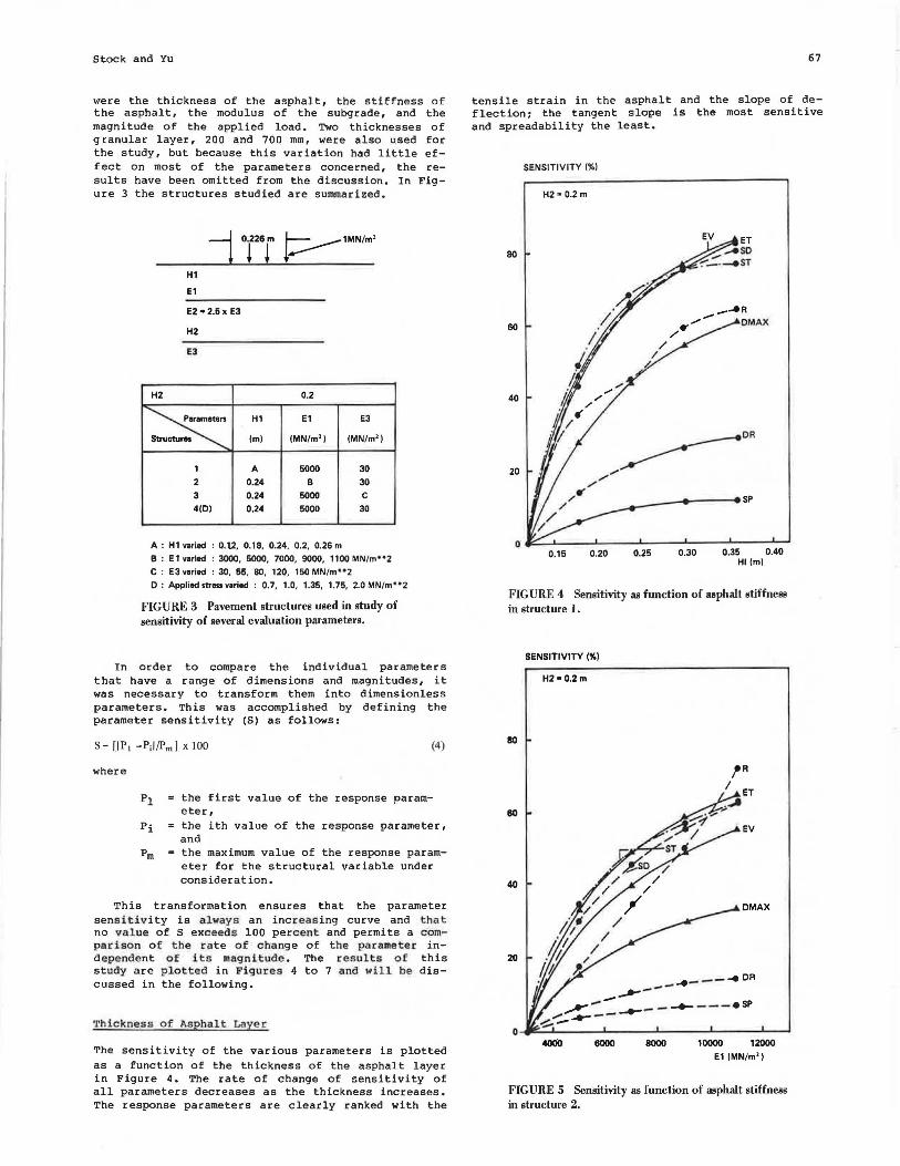
were the thickness of the aspha lt, the stiffness of the asphalt, the modulus of the subgrade, and the magnitude of the applied load. Two thicknesses of granular layer, 200 and 700 mm, were also used for the study, but because this variation had little effect on most of the parameters concerned, the results have been omitted from the discussion. In Figure 3 the structures studied are summarized.
HZ
H1
E1
j
E2•2.5x E3
H2
EJ
~ ... 1
2
3 4(0)
0.226m
! !
H1
(m)
A
0.24
0.24
0.24
!.::.::::---1MN/m1
0.2
E1 E3
(MN/m1 ) (MN/m1 )
5000 30
B 30
5000 c 5000 30
A : H 1 voried : 0. U, 0. 18, 0.24, 0.2, 0.26 m
B : ET varied : 3000, 5000, 7000, 9000, T TOO MN/m .. 2
C : E3 varied : 30, 55, 80, 120, 150 MN/m .. 2
D : Applied streu varied : 0.7, 1.0, 1.35, 1.75, 2.0 MN/m .. 2
FIGURE 3 Pavement structures used in study of sensitivity of several evaluation parameters.
In order to compare the individual parameters that have a range of dimensions and magnitudes, it was necessary to transform them into dimensionless parameters. This was accomplished by defining the parameter sensitivity (S) as follows:
S= [IP1-P;l/PmJ x1 00 (4)
where
P1 the first value of the response parameter, the ith value of the response parameter, and
Pm the maximum value of the response parameter for the structural variable under consideration.
This transformation ensures that the parameter sens i t i vity is a l ways an increas ing curve and that no va l ue of s exce eds 100 percent and permits a c ompa ri son o f the r a te o f c hange of t he parameter ind ependent of i t s mag n itude . The results o f this s tudy a re plotted in Figu r es 4 to 7 and will be discussed in the following.
Th ickness o f Aspha l t Layer
The sensitivity of the various parameters is plotted as a function of the thickness of the asphalt layer in Figure 4. The rate of change of sensitivity of all parameters decreases as the thickness increases. The response parameters are clearly ranked with the
67
tensile strain in the asphalt and the slope of deflection i the tangent slope is the most sensitive and spreadability the least.
SENSITIVITY (%)
H2 • 0.2 m
80
60
40
20
0.15 0.20 0.25 0.30 0.35 0.40 Hl(m)
FIG URE 4 Sensitivity as function of asphalt stiffness in structure 1.
SENSITIVITY (%)
H2 • 0.2 m
ao
60
EV
40
DMAX
20
... ___ ... DR -----.....--- -------•SP ,,. ...... -- ........
?-
6000 8000 10000 12000 E1 (MN/m1 )
FIGURE 5 Sensitivity as function of asphalt stiffness in structure 2.
68
SENSITIVITY (%)
H:?-0.2 m
80
60
40
20
40 60 80 100 120 140 E3 (MN/m1 )
EV DMAX
160
FIGURE 6 Sensitivity as function of subgrade modulus in structure 3.
Stiffness of Asphalt Layer
Figure 5 is a plot of sensitivity as a function of the stiffness of the asphalt layer. With the exception of the radius of curvature, the response parameters are ranked in the same order as those for sensitivity to the asphalt layer thickness, although they tend to fall into distinr.r gr0•1ps " The ?:adh:e of curvature exhibits the useful characteristic of a uniform rate of change with respect to asphalt stiffness and is most sensitive to stiffness at the maximum value selected for this study.
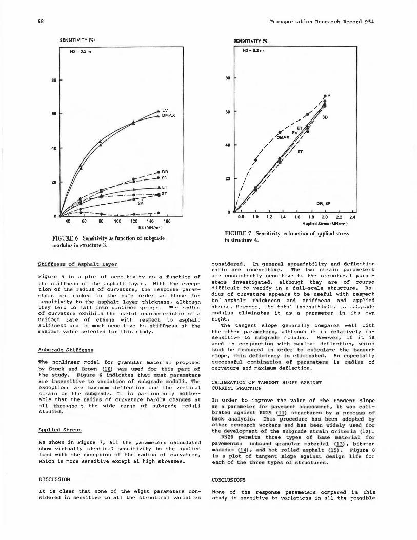
Subgrade Stiffness
The nonlinear model for granular material proposed by Stock and Brown (10) was used for this part of the study. Figure 6 indicates that most par-ameters are insensitive to variation of subg rade moduli. The exceptions are maximum deflection and the vertical strain on the subgrade. It is particularly n.oticeable that the radius of curvature hardly changes at all throughout the wide range of subgrade moduli studied.
Applied Stress
As shown in Figure 7, all the parameters calculated show virtually identical sensitivity to the applied load with the exception of the radius of curvature, which is more sensitive except at high stresses.
DISCUSSION
It is clear that none of the eight parameters considered is sensitive to all the structural variables
BO
80
40
20
Transportation Research Record 954
SENSITIVITY (%)
H2•0.2m
I I
I I
I v I ~
0.8
/ ,,,. / ET
W' EV~~ //oMAX ~/
/ {/ / / ST ' / I
DR,SP
1.0 1.2 1.4 1.6 1.8 2.0 2.2 2.4 Applied Strfts (MN/m')
FIGURE 7 Sensitivity as function of applied stress in structure 4.
considered. In general spreadability and deflection ratio are insensitive. The two strain parameters are consistently sensitive to the structural parameters investigated, although they are of course difficult to verify in a full-scale structure. Radius of curvature appears to be useful with respect to ' asphalt thickness and stiffness and applied
modulus eliminates it as a parameter in its own right.
The tangent slope generally compares well with the other parametets, although it is relatively insensitive to subgrade modulus. However , if it is used in conjunction with maximum deflection, which must be measured in order to calculate the tangent slope, this deficiency is eliminated. An especially successful combination of parameters is radius of curvature and maximum deflection.
CALIBRATION OF TANGENT SLOPE AGAINST CURRENT PRACTICE
In order to improve the value of the tangent slope as a parameter for pavement assessment, it was calibrated against RN29 (11) structures by a process of back analysis. This procedure has been adopted by other research workers and has been widely used for the development of the subgrade strain criteria (12) •
RN29 permits three types of base material for pavements: unbound granular material (!1), bitumen macadam (14), and hot rolled asphalt (15). Figure 8 is a plot of tangent slope against design life for each of the three types of structures.
CONCLUSIONS
None of the response parameters compared in this study is sensitive to variations in all the possible

Stock and Yu
Key
A : Unbound granular base B : Hot rolled asphalt ba"'
69
C : Dense bitumen macadam ba!e
I\ ,..
~
""' ,..
"" ""' ' 'r--~"--
e ---t--_ r-.... C, r-i--r---- .....
2.0
! E
1.5 ! & 0 ;;; E & c . 1.0 I-
" .c I-
0.5
106 107 10• Number of Standard axle Application5
FIGURE 8 Tangent-slope values for typical RN29 structures.
structural parameters in a pavement. The tangentslope response parame ter is adequate ly sensitive to mOS!t structura l parameters. It includes variations in both maximum deflection and the shape of the deflected surface and can therefore describe a pavement unambiguously.
ACKNOWLEDGMENT
The authors would like to thank Imperial Chemical Industries, Ltd., for financial and technical assis t a nce d uring this p r ojec t . The support o f A. E. Va r dy , head of the Department of Civil Engineer ing at Dunde e Un i versity, is also acknowledged, as is the assistance of the Computing Centre.
REFERENCES
1 . Proc., Fourth International Conference on the Structural Design of Asphalt Pavements. University of Mi ch i gan, Ann Arbor, 1977.
2. Y. Miura and R. Tobe . Evaluation of Existing Pavements Based on Deflection and Radius of Curvature and Overlay Design. Proc., Fourth International Conference on the Structural Design of Asphalt Pavements, University of Michigan, Ann Ar bor , 1977.
3. A.I.M. Claesse.n , C.P. Valkering, and R. Ditmarsch. Pavement Evaluation with the Falling Weight Deflectometer. Proc., AAPT, Vol. 45, 1976.
4. P.G. Rufford. A Pavement Analysis and Structural Design Procedure Based on Deflection. Proc., Fourth International Conference on the Structural Design of Asphalt Pavements, University of Michigan, Ann Arbor, 1977.
5. F.N. Hveem. Pavement Deflection and Fatigue Failures. Bull. 114. HRB, National Research Council, Washington, D.C., 1955, pp. 43-73.
6. M.C. Ford, Jr., and J.R. Bisselt. Flexible Pavement Performance Studies in Arkansas. Bull. 321. HRB, National Research Council, Washington, D.c., 1962, pp. 1-15.
7. K.Y. Kung. A New Method in Correlation Studies of Pavement Deflection and Cracking. Proc., Second International Conference on the Structural Design of Asphalt Pavements, University of Michigan, Ann Arbor, 1967.
8. M.G.F. Peutz, A. Jones, and H.P.M. van Kempen. Compu ter Progr am BISTRO : Layered Systems under Normal Loads . Ex-ternal Report. Kon iniklijke/ Shell Laboratorium, Amsterdam, Netherlands, 1967.
9. M.G. Cox and J .G. Hayes. Curve Fitting: A Guide and Suite of Algorithms for the Non-Specialist User. Report NAC26. National Physical Laboratory, Teddington, Middlesex, England, 1973.
10. A.F. Stock and S.F. Brown. The Nonlinear Characterization of Granular Materials for Asphalt Pavement Design. In Transportation Research Record 755, TRB, National Research Council, Washington, D.C., 1980, pp. 14-20.
11. A Guide to the Structural Design of Pavements for New Roads, 3rd ed. TRRL Road Note 29. U.K. Transport and Road Research Laboratory, Crowthorne, Berkshire, England, 1970.
12. S.F. Brown, P.S. Pell, and A.F. Stock. The Application of Simplified Fundamental Design Procedures for Flexible Pavements. Proc., Fourth International Conference on the Structural Design of Asphalt Pavements, University of Michigan, Ann Arbor, 1977.
13. Specification for Road and Bridgeworks. TRRL, Crowthorne, Berkshire, England, 1969.
14. Coated Macadam for Roads and Other Paved Areas. B.S. 4987. British Standards Institution, London, 1973.
15. B.S. 594. British Standards Institution, London, 1973.
Publication of this paper sponsored by committee on Flexible Pavements.