user manual - marine electronics for nmea 2000 networks · user manual digital thermometer ... •...
TRANSCRIPT

User Manual
Digital Thermometer YDTC-13Digital Barometer YDBC-05
also covers modelsYDTC-13R, YDTC-13RT, YDTC-13N, YDTC-13NT
YDBC-05R, YDBC-05RT, YDBC-05N, YDBC-05NTSoftware version 1.25
2016

© 2015 Yacht Devices Ltd. Document YDBC05TC13-005. June 21, 2016. Web: http://www.yachtd.com/
NMEA 2000® is a registered trademark of the National Marine Electronics Association. SeaTalk NG is a registered trademark of Raymarine UK Limited. Garmin® is a registered trademark of Garmin Ltd.

Contents
Introduction .4 Warranty and Technical Support .6 Product Specification .7 Device Connection and Testing .9 Programming the Device 14 APPENDIX А. Troubleshooting 23 APPENDIX B. Description of Connectors and Joints 25 APPENDIX С. NMEA 2000 Messages 27
Package ContentsDevice 1 pc.This Manual 1 pc.

— 4 —
Introduction
This Manual contains information on how to install, configure and operate YDTC-13 digital thermometers (hereinafter Thermometer) and YDBC-05 digital barometers (hereinafter Barometer) intended for use on pleasure crafts.
The Thermometer and Barometer (hereinafter, where the differences are not critical, Devices) have one digital sensor. Up to 50 devices may be used on a vessel simultaneously; this limitation is set by the network specification. Data from the Devices can be displayed on chartplotters, digital navigation instruments, as well as used by other digital equipment of the vessel.
The Thermometer performs measurements within the range from -55 to +125 °С (-67..+257 °F), the sensor is placed outside the case on a flexible 95cm-long wire in a sealed stainless steel sleeve and can be used to measure the temperature of gases and liquids. The wire, if necessary, can be elongated up to 100 meters. The Thermometer can be configured to display its data as "Air temperature", "Sea temperature", "Temperature in the refrigerator", "Temperature in the engine room", etc.
The Barometer is intended for measuring atmospheric pressure within the range from 300 to 1100 hPa (mbar). The sensor is located inside the device case. The Barometer identifier can be configured so that data from several Barometers will be simultaneously displayed on a chartplotter.
The Devices are designed for operating in an NMEA 2000 network and are compatible with a wide range of equipment supporting this protocol. Raymarine SeaTalk NG, Simrad SimNet, Furuno CAN networks are branded versions of NMEA 2000 and differ only in the type of connectors. In its devices, Garmin uses the NMEA 2000 Micro connector which is compatible with the DeviceNet Micro connector. Our

— 5 —
Devices are supplied with different types of connectors, making it possible to connect them to networks of different manufacturers without any adapters. The Device model is shown on the case.
Device model Type of the connector, compatibility (see Appendix B)
YDBC-05R, YDTC-13R Raymarine SeaTalk NG Female
YDBC-05RT, YDTC-13RT Raymarine SeaTalk NG Female Terminator
YDBC-05N, YDTC-13N,YDBC-05NT, YDTC-13NT
NMEA 2000 Micro Male, DeviceNet Micro Male, Garmin NMEA 2000 Male
To connect to other types of NMEA 2000 networks, a cable adapter is required (it is not supplied with the Device and must be purchased separately). Note that the Devices are not compatible with the NMEA 0183 protocol.
According to the specification, an NMEA 2000 network has two terminators (120-Ohm resistors) connected to the NMEA 2000 bus ends. Device models with the T index at the end of their names contain a built-in terminator and should be connected to the network instead of the terminator. This allows a zero-cost connection of the Devices to existing networks with no free connectors. Please note that according to the specification, you can not use more than two devices with the T index on one NMEA 2000 bus.
We thank you for purchasing our Devices and wish you happy voyages!

— 6 —
Warranty and Technical Support
1. The Device warranty is valid for two years from the date of purchase. If a Device was purchased in a retail store, when applying under a warranty case, the sale receipt may be requested.
2. The Device warranty is terminated in case of violating the instructions of this Manual, case integrity breach, repair or modification of the Device without manufacturer’s written permission.
3. Modification of the Thermometer sensor cable is performed by the user at his own risk, the warranty does not cover the Device failure in this case.
4. If a warranty request is accepted, the defective Device must be sent to the manufacturer.
5. The warranty liabilities include repair and replacement of the goods and do not include the cost of equipment installation and configuration, as well as shipping the defective Device to the manufacturer.
6. Responsibility of the manufacturer in case of any damage as a consequence of the Device operation or installation is limited to the Device cost.
7. The manufacturer is not responsible for any errors and inaccuracies in guides and instructions of other companies.
8. The Device requires no maintenance. Device’s case is non-dismountable. If the event of a failure, please refer to Appendix A before contacting the technical support.
9. The manufacturer accepts applications under the warranty and provides technical support only via e-mail or from authorized dealers.
10. Contact details of the manufacturer and a list of the authorized dealers are published on the website: http://www.yachtd.com/.

— 7 —
Product Specification
Figure 1. Combined drawing of the Thermometer and Barometer

— 8 —
Device parameter Value Unit
Operating voltage (from an NMEA 2000 network) 7..16 V
Protection against reverse polarity Yes —
Consumption current of the Thermometer / Barometer 24 / 24 mA
Load Equivalency Number 1 LEN
Operating temperature range (except the Thermometer sensor) -40..+80 °С
Weight of the Thermometer / Barometer 31 / 11 g
NMEA 2000 data output resolution 0.01 °С / hPa
Parameters of the Barometer
Measurement range 300..1100 hPa
Relative measurement accuracy ± 0.12 hPa
Absolute measurement accuracy, at 0..+65 °С ± 1 hPa
Absolute measurement accuracy in the rest of the range ± 2.5 hPa
Parameters of the Thermometer
Measurement range -55..+125 °С
Error of the thermometer within the range of -10..+85°C, max ± 0.5 °С
Error of the thermometer within the rest of the range, max ± 2 °С

— 9 —
Device Connection and Testing
The Device requires no maintenance; calibration of the digital sensors has been performed by the manufacturer.
When deciding where to install the Device, choose a dry mounting location. Avoid places where the Device can be flooded with water, this can damage it. The Thermometer sensor has a waterproof case made of stainless steel and is not intended for permanent location in hostile environments such as sea water. To prevent corrosion, when installing outdoors protect the sensor case with the help of a coating of paint.
Read the model number on the Device case. If the model name has the T index at the end (for example, YDBC-05NT), then the device has a built-in terminator (with resistance of 120 Ohm) and must be connected to the bus instead of an existing terminator. Different connectors for terminators (blue) and devices (white) are used in the SeaTalk NG network, which eliminates the chance to err. In networks with the NMEA 2000 Micro connectors (DeviceNet Micro, Garmin NMEA 2000), devices are connected to the Female connector on the bus, while terminators are connected to both Male and Female connectors.
The Device is directly connected to the bus without a drop cable. Before connecting the Device, turn off the bus power supply. Refer to the manufacturer's documentation if you have any questions regarding the use of connecting cables, terminators and connectors:
• SeaTalk NG Reference Manual (81300-1) for Raymarine networks• Technical Reference for Garmin NMEA 2000 Products (190-00891-00) for
Garmin networks

— 10 —
After connecting the Device, close the lock on the connection to ensure its water resistance and reliability.
Figure 1. SeaTalk NG bus with the YDBC-05RT, YDTC-13R and YDBC-05R (left to right)
After turning on the bus power supply, the Device LED will produce short signals every 2 seconds.
If the Device is connected to a network having a chartplotter or any other device transmitting a PGN 0x1F814 (129044) message with chart datum configuration or

— 11 —
PGN 0x1F11A (127258) with data on magnetic variation, the Device will produce six LED signals with a period of 0.5 seconds when such message is received for the first time after power is on. This usually happens within 15 seconds after the Device is turned on. The signal series confirms the Device is properly connected to the NMEA 2000 network and the chartplotter is able to receive data from the Device.
The Device information should be displayed in the list of NMEA 2000 devices (SeaTalk NG, SimNet, Furuno CAN) or in the common list of external devices on the chartplotter (see Figure 2). Usually, access to this list is in the "Diagnostics", "External Interfaces" or "External devices" menu.
Data from the Device are available to all the equipment connected to the network and can be displayed simultaneously on several chartplotters and digital navigation instruments.
Under the factory settings, the Thermometer shows measured data as air temperature. The Barometer always shows the measured data as atmospheric pressure, regardless of the user’s settings.
Switch to the chartplotter screen, which provides information about the atmospheric pressure (for the Barometer) and air temperature (for the Thermometer) or add this indicator to the screen using instructions supplied with your equipment. Data in the indicator should begin to appear no later than 5 seconds after turning the Device on. Data is updated at an interval of two seconds.
Many chartplotters and digital navigation instruments are able to display data on pressure and temperature in the form of graphs; this allows tracking of trends in the weather. The digital indicator can also contain a trend pointer (see Figure 3).

— 12 —
Figure 2. Raymarine c125 MFD devices list with Barometer and Thermometer
The Thermometer can be reprogrammed by the user to display data in other indicators, such as «Sea temperature», «Temperature in the engine room», «Temperature in the refrigerator» (see «Programming the Device»).
The Thermometer sensor cable can be elongated up to 100 m by the user himself

— 13 —
Figure 3. Garmin GPSmap 721 display with the connected Barometer and
two Thermometers
(note that the warranty for the modified Device is not maintained). To do this, turn the Device off, cut the cable in the middle (see Appendix B) and extend it with a three-conductor wire and properly insulate the joints. The wires are recommended to be connected by crimping in sleeves rather than soldering. Soldered connections can quickly break down in the marine environment.
— 14 —
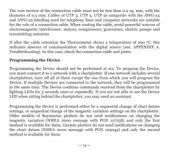
The core section of the connection cable must not be less than 0.2 sq. mm, with the diameter of 0.5 mm. Cables of UTP 3, UTP 5, UTP 5e categories with the AWG-24 and AWG-22 labelling used for telephone lines and computer networks are suitable for the role of a connection cable. When routing the cable, avoid powerful sources of electromagnetic interference: motors, compressors, generators, electric pumps and transmitting antennas.
If after the cable extention the Thermometer shows a temperature of 290 °C, this indicates absence of communication with the digital sensor (see. APPENDIX A. Troubleshooting). In this case, check the connection cable and joints.
Programming the Device
Programming the Device should not be performed at sea. To program the Device, you must connect it to a network with a chartplotter. If one network includes several chartplotters, turn off all of them except the one from which you will program the Device. If multiple Devices are connected to the network, they will be programmed at the same time. The Device confirms commands received from the chartplotter by lighting LEDs for 3 seconds once or repeatedly. If you are not able to see the Device LED when sitting behind the chartplotter, you may need an assistant.
Programming the Device is performed either by a sequential change of chart datum settings, or sequential change of the magnetic variation settings on the chartplotter. Older models of Raymarine plotters do not send notifications on changing the magnetic variation (NMEA 2000 message with PGN 127258) and only the first method is available for them. Garmin plotters do not send notifications on changing the chart datum (NMEA 2000 message with PGN 129044) and only the second method is available for them.

— 15 —
Figure 1. Setting the chart datum and magnetic variation on Raymarine c125
To select a programming method, refer to the documentation of your chartplotter. In some cases you may need to update the plotter firmware. Theoretically, programming the Device can be performed using a plotter of any manufacturer.

— 16 —
STEP 1. Putting the Device into standby mode
The Device enters standby mode if, when it is switched on, the chart datum is set on the plotter as follows:
• to “Australian Geodetic 1966” for the Thermometer• to “European 1950 (Mean, European Datum)” for the Barometer
Or if the magnetic variation on the plotter is set to a user-defined value with the following parameter:
• 28°W for the Thermometer• 29°E for the Barometer
Usually the plotter sends notifications on settings every 20 seconds. When changing the setting on the plotter as mentioned above, do not forget to remember the initial configuration of the plotter. Cycle the Device power. Within a minute after the Device is turned on, it will produce a confirmation signal (LED will light up for 3 seconds). This means that the Device is put into standby mode. If the Device power is turned off along with the plotter power, the wait time for the signal will be increased by the plotter loading time.
If after some time the setting on the plotter automatically returns to the previous value, it means that there is another device in the network sending notifications. It may be an NMEA0183-NMEA2000 converter, another plotter, or a computer connected to the NMEA 2000 network. Turn off the power of this device or disconnect it from the NMEA2000 bus at the time of programming. It is recommended to disconnect any such device from the bus when the bus power is off.

— 17 —
STEP 2. Putting the Device into programming mode
If the Device was put into standby mode by setting the chart datum (magnetic variation), all the subsequent steps should be carried out with the setting of chart datum (magnetic variation).
In the standby mode, without turning the Device power off, change the chart datum setting on the plotter
• to “European 1950 (Mean, European Datum)” for the Thermometer• to “Australian Geodetic 1966” for the Barometer
Or change the magnetic variation setting to:
• 29°E for the Thermometer • 28°W for the Barometer
The Device will produce one confirmation signal and enter programming mode.
The programming mode ends automatically 10 minutes after the Device power is turned on. Four confirmation signals are produced at the same time. After that, the Device returns to normal operation mode. The settings are not saved into non-volatile memory and if the Device settings were changed at the time of programming, they will be kept only until the Device power is turned off.
STEP 3. Programming the Device
When programming, you can customize the list of NMEA 2000 messages containing data sent by the Device, as well as the type of the transmitted data (for the
— 18 —
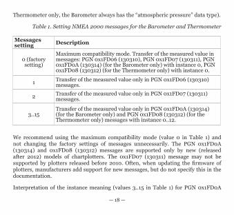
Thermometer only, the Barometer always has the “atmospheric pressure” data type).
Table 1. Setting NMEA 2000 messages for the Barometer and Thermometer
Messages setting Description
0 (factory setting)
Maximum compatibility mode. Transfer of the measured value in messages: PGN 0x1FD06 (130310), PGN 0x1FD07 (130311), PGN 0x1FD0A (130314) (for the Barometer only) with instance 0, PGN 0x1FD08 (130312) (for the Thermometer only) with instance 0.
1 Transfer of the measured value only in PGN 0x1FD06 (130310) messages.
2 Transfer of the measured value only in PGN 0x1FD07 (130311) messages.
3..15Transfer of the measured value only in PGN 0x1FD0A (130314) (for the Barometer only) and PGN 0x1FD08 (130312) (for the Thermometer only) messages with instance 0..12.
We recommend using the maximum compatibility mode (value 0 in Table 1) and not changing the factory settings of messages unnecessarily. The PGN 0x1FD0A (130314) and 0x1FD08 (130312) messages are supported only by new (released after 2012) models of chartplotters. The 0x1FD07 (130311) message may not be supported by plotters released before 2010. Often, when updating the firmware of plotters, manufacturers add support for new messages, but do not specify this in the documentation.
Interpretation of the instance meaning (values 3..15 in Table 1) for PGN 0x1FD0A

— 19 —
(130314) and PGN 0x1FD08 (130312) depends on the plotter manufacturer. Data on the refrigerator temperature with instance 3 can be displayed as “Temperature in refrigerator № 3”. In practice, we have not seen plotters with such ability.
Please note that all the messages transmitted by the Device are informational. They can be used by other devices during their operation (to show them on a display or to trigger an alarm when exceeding a predetermined level), but are not used as automated control data for autotuning. Transmitting data on the cabin temperature will not change the operating mode of the cabin heater.
You can choose one of the 14 types of data sources for the Thermometer. Note that, for example, data on the engine room temperature (value 3 in Table 2) can be send only in the PGN 0x1FD07 (130311) or 0x1FD08 (130312) messages. If you change the message setting to the value of 1 (see Table 1) and allow only PGN 0x1FD06 (130310) messaging, the Thermometer will stop transmitting temperature data as engine room temperature cannot be sent in this message. When configuring messages with the value of 0 (see Table 1) and data source with the value of 13 (Freezer temperature, see Table 2), only PGN 0x1FD08 (130312) messages will be transmitted, because these data can not be transferred in other messages.
Regardless of settings, the Device receives and transmits NMEA 2000 service messages (see Appendix C) and is displayed in the list of NMEA 2000 devices (SeaTalk NG, SimNet, Furuno CAN).
Programming the Device is performed by changing the chart datum or magnetic variation setting on the plotter. The Device confirms the command by producing a single signal (unless shown otherwise in Table 3). The Device must be previously put into programming mode (STEP 2).

— 20 —
Table 2. Setting type of a data source for the Thermometer
Data type setting Description
NMEA 2000 messages, PGN
0x1FD06 (130310)
0x1FD07 (130311)
0x1FD08 (130312)
0 Sea Temperature. Yes Yes Yes
1 (factory setting) Outside Temperature. Yes Yes Yes
2 Inside Temperature. - Yes Yes3 Engine Room Temperature. - Yes Yes4 Main Cabin Temperature. - Yes Yes5 Live Well Temperature. - - Yes6 Bait Well Temperature. - - Yes7 Refrigeration Temperature. - - Yes8 Heating System Temperature. - - Yes9 Dew Point Temperature. - - Yes
10 Wind Chill Temperature, Apparent. - - Yes
11 Wind Chill Temperature, Theoretical. - - Yes
12 Heat Index Temperature. - - Yes13 Freezer Temperature. - - Yes

— 21 —
Table 3. Device actions in response to setting changes
Chart datum Magnetic variation Result
Bermuda 1957 20°E Incrementing the message setting by one. Upon reaching 16, the setting value is set to zero.
Bogota Observatory (Colombia)
21°E Incrementing the message setting by one. Upon reaching 16, the setting value is set to zero.
ARC 1950 (Africa) 22°E
Incrementing the message setting by 5. Upon reaching or exceeding 16, the setting value is set to zero.
Campo Inchauspe (Argentina)
23°E Reset the message setting to zero (resetting to factory setting). Two confirmation signals.
Guam 1963(Pacific Ocean) 24°E
For Thermometer only. Incrementing the data type setting by one. Upon reaching 14, the setting value is set to zero.
Hjorsey 1955 (Ireland) 25°E
For Thermometer only. Incrementing the data type setting by one. Upon reaching 14, the setting value is set to zero.
Ireland 1965 26°EFor Thermometer only. Incrementing the data type setting by 5. Upon reaching or exceeding 14, the setting is reset to zero.
Liberia 1964(Africa) 27°E For Thermometer only. Reset the data type setting
to zero. Two confirmation signals.

— 22 —
Please note that changing the Device settings occurs only when changing the plotter configuration. To increase the value of the message setting by 3, first change the setting to the first value from Table 3, then to the second, and then back to the first one. After each change, wait for the Device confirming signal (lighting of LEDs for 3 seconds). Usually, when changing the setting, the plotter sends notification immediately and the Device signals just after the setting value is changed.
STEP 4. Saving the settings in the non-volatile memory
Without turning the Device power off, change the chart datum setting on the plotter for “WGS 1984”, or magnetic variation setting for 27°W. The device will save the settings in the non-volatile memory, produce three confirming signals, and return to normal operation mode.
If you do not save the settings into the non-volatile memory, they will be kept only until the power is turned off (see STEP 2).
Do not forget to return the initial chartplotter settings after programming.

— 23 —
APPENDIX А. Troubleshooting
Fault Possible reasons and solution
The LED does not signal after the Device is turned on
1. No power supply on the bus. Check if the bus pow-er is supplied (NMEA 2000 network requires a separate power connection and can not be powered by a plotter or another Device connected to the network). 2. Loose connection in the power supply circuit. Treat the Device connector with a spray for cleaning electrical contacts. Plug the Device into another connector.
The Device LED flashes every two seconds, but the Device is not displayed in the list of external devices on the plotter, data do not appear, a series of six LED signals with a period of 0.5 seconds is not observed within a minute after switching on the Device and the plotter
1. Loose connection in the data circuit. Treat the Device connector with a spray for cleaning electrical con-tacts. Plug the Device into another connector. 2. There are problems in the NMEA 2000 network. The network segment is not connected to the plotter or there are missing terminators in the network. Plug another de-vice into the selected connector and make sure it appears in the list of devices on the plotter. Note: If the Device is connected to a network with a plotter, upon receiving the first PGN 0x1F814 (129044) chart datum message or PGN 0x1F11A (127258) magnetic variation message, the Device will give a series of six LED signals with a period of 0.5 seconds. This should happen within a minute after switching on the Device and the plotter.

— 24 —
Table continued
Fault Possible reasons and solution
The Device is displayed in the list of Devices, but data do not appear on the screen
1. Incorrect Device settings. Put the Device into the programming mode and reset it to the factory settings. 2. Incompatible equipment. Make sure that your hardware supports messages transferred by the Device. Update the firmware of your equipment if necessary.
The Thermometer shows the temperature of 290 degrees Celsius
1. There is no connection to the digital sensor. Make sure the sensor or wire is not damaged. 2. Interference in the sensor signal. Make sure the sensor wire does not lie in the neighborhood of any sources of powerful electromagnetic interference (electric motors, transmitting antennas, etc.).

— 25 —
APPENDIX B. Description of Connectors and Joints
Figure 1. Connectors of the Devices with indices R (left), RT (center), N and NT (right) in the end of model name

— 26 —
Figure 2. Digital sensor of the Thermometer

— 27 —
APPENDIX С. NMEA 2000 Messages
Message Rec- eive
Tran- smit
Period, sec Comments
ISO AcknowledgmentPGN 059392 (0x0E800) Yes Yes -
ISO RequestPGN 059904 (0x0EA00) Yes - -
ISO Address ClaimPGN 60928 (0x0EE00) Yes Yes -
PGN List Group FunctionPGN 126464 (0x1EE00)
- Yes -
Product InformationPGN 126996 (0x1F014) - Yes 60
Periodic transmission is performed for compatibility with some models of equipment.
DatumPGN 129044(0x1F814) Yes - - Used for Device programming.
Magnetic VariationPGN 127258 (0x1F11A) Yes - - Used for Device programming.

Message Rec- eive
Tran- smit
Period, sec Comments
Environmental ParametersPGN 130310 (0x1FD06)
- Yes 2 Can be disabled when a user is programming the Device.
Environmental ParametersPGN 130311 (0x1FD07)
- Yes 2Can be disabled when a user is programming the Device.
TemperaturePGN 130312 (0x1FD08) - Yes 2
Thermometer only. Can be disabled when a user is programming the Device.
Actual Pressure PGN 130314 (0x1FD0A) - Yes 2
Barometer only. Can be disabled when a user is programming the Device.
Table continued