using saudi natural soils from jeddah-makkah boundaries as ... · cities in western region of saudi...
TRANSCRIPT
Using Saudi Natural Soils from Jeddah-Makkah Boundaries as Liner
Bed in Sanitary Landfills, Suitability Study
M. AboushooK1
, M. N. Fatani2, H. Abdulrahman
3, A. Fadol and M. Kotob
4
1,2Faculty of Engineering, King Abdulaziz University, KAU, Jeddah, Saudi Arabia
3Faculty of Environmental Designs, KAU, Jeddah, Saudi Arabia
4Faculty of Engineering, KAU, Jeddah, Saudi Arabia
Abstract. Thirteen locations in Jeddah-Makkah boundaries in Saudi Arabia containing clayey soils were
selected, based on previous geological studies, to test the possibility of using natural soils brought from these
sites as liner-bed in solid waste landfills. The main function of the liner-bed layer in solid waste landfills is to
protect underground water aquifer against contamination from infiltrated pollutants. Physical and engineering
properties of soil samples brought from these locations are investigated. The permeability of a liner bed
material should not exceed a limiting value of 1x 10⁻⁷
cm/sec while the total shear strength (t) at saturation
state should not be less than 50 kPa at 200 kPa of normal stress (n). Most of the engineering properties are
measured at a fixed initial state of the standard Proctor optimum moisture content (wopt.) and maximum dry
density (dmax.). Most of the soil samples from Makkah-Jeddah area were classified as clayey type soils. Four
out of the thirteen samples met both requirements of permeability limit and shear strength, while a pair of
samples met the permeability limit condition only and another pair met the shear strength requirement only.
The rest of samples did not meet any condition. As a conclusion four samples were found to be suitable as
liner bed material while nine samples were found to be unsuitable.
Keywords: Natural soils, Solid waste, Underground water, contamination, Permeability, Shear strength
1. Introduction
Solid waste management is one of the serious problems with growing potential in developing countries
such as Saudi Arabia. Poor management of solid waste may lead to severe soil and groundwater
contamination resulting in adverse health hazard [1]-[3]. One of the practical solutions, of such a problem, is
achieved by enclosing the solid wastes in a specific location (dump) and using insulated container to prevent
percolation of waist liquids. For economic construction, engineers use insulating soil barrier called "liner
bed" at the base of the solid waste dump. The liner bed material should be impervious to prevent infiltration
of pollutants such as heavy metals and other toxic materials into groundwater aquifer. It should also be
strong enough to resist shear failure that may be caused by the weight of the solid wastes [4]. To build more
economical solid waste dump, the use of local natural materials should be investigated. Natural clayey soils
or modified mixture of such soils with bentonite could be used [5], [6]. For one of these materials to be
suitable as compacted soil bed, it should meet the conditions of permeability and shear strength [6].
According to [7], [8], the permeability of a liner bed material should not exceed a limiting value of 1x 10⁻⁷
cm/sec and the total shear strength (
n). The efficiency of this bed depends largely on the hydro-mechanical behavior of the
soil along with its capacities of attenuation and retention of the liquid component of the contaminant [8]. If
suitable earthen material is available on or near the site of construction, a lining of compacted earth is
considered economical and efficient means of controlling percolation. A well- compacted lining of such soil
can be highly impermeable, satisfying the above-mentioned requirements for liner bed material.
Corresponding author. Tel.: +966568365313
E-mail address: [email protected].
International Proceedings of Chemical, Biological and Environmental Engineering, Vol. 88 (2015)
DOI: 10.7763/IPCBEE. 2015. V88. 14
81

This paper investigates the suitability of using natural clay soils around the boundaries of two major
cities in Western region of Saudi Arabia as liner bed in solid waste dumps. These cities are, Makah and
Jeddah. The liner bed would be constructed at the bottom of the solid waste landfill at a depth of 25-30 m
below ground level. Soils at Makah and Jeddah locations are considered to be similar in the geological origin
and soil condition. Eight test sites (S1-S8) were chosen within Jeddah region, while five test sites (S9-S13)
were considered for Makah region. The locations of these sites are shown on the geological map of these
regions (Fig. 1). The physical and engineering properties of soils under investigation have been determined
based on ASTM specifications [8]. All engineering properties measurements were conducted through a fixed
initial state of standard Proctor optimum moisture content (wopt.) and maximum dry density (dmax.). However,
the swelling potential and settlement behavior were measured according to the modified Proctor conditions.
In this paper, the physical characterization of all soil samples will be discussed. Then, the engineering
behavior of these natural soils is investigated. The suitability of each of these materials as liner bed is then
determined based on the conditions of permeability and shear strength.
Fig. 1: Location and Geologic map of Jeddah-Makah Quadrangle showing the locations of the investigated clay deposits
(Modified after [9]
).
0
10
20
30
40
50
60
70
80
90
100
0 10 20 30 40 50 60 70 80 90 100
CL-ML
CH
CL
MH or OHMLH or OL
S1
S8
S6
S2
S4
S12
S10
S13
S3
S11
S7
S9
S5
Liquid limit
Plas
tici
ty in
dex
%
Figure 3.8: Location of studied samples on Cassegrand Chart
CL-ML
CH
CL
MH or OHMLH or OL
S1
S8
S6
S2
S4
S12
S10
S13
S3
S11
S7
S9
S5
CL-ML
CH
CL
MH or OHMLH or OL
S1
S8
S6
S2
S4
S12
S10
S13
S3
S11
S7
S9
S5
Fig. 2: Location of soil samples on Cassegrand chart
2. Physical Characterization
82

Physical characterizations are meant to provide a rational basis for verifying the suitability of natural
soils extracted from chosen sites in Jeddah- Makah region to be used in the liner system of waste
management structures. Visual description is summarized in Table 1. Sample photographs given in this table
show that most samples look like natural shale soils which are hard in dry state and tend to swell and soften
in wet state as indicated by the free swell (FS) values in Table 2. The following physical properties are
determined, according to ASTM Standard Specifications [8] to identify the studied soils in point of view
their suitability to be a liner: Moisture content and density; Fines percentage and clay content; Plasticity
characteristics and activities. Field density and moisture content deduced from undisturbed samples and
presented in Table 2, indicate relatively high values of field dry density and low values of moisture content.
That reflects hardness of natural samples. The high maximum dry density of compacted soils also reflects
good strength conditions. The percentages of sand, silt and clay contents are also listed in the Table 2. Most
of the natural samples, except S6, have more than 20 % fines (silt & clay); 10% clay; 7% plasticity index
and 0.3 activities. From the Casegrand chart, the most studied natural soils are classified as silty clay with
high to low plasticity (CL or CH) (Fig. 2). All the physical properties results are summarized in Table 3.
Comparison between standard and modified Proctor compaction of studied soils (Table 2), most of studied
soils have tendency to absorb more compaction energy.
Therefore, most of studied soils are expected to become suitable materials for a bed liner compaction.
That means that the most studied samples are suitable to be liner materials from the point of view of physical
properties according to the specification of liner materials, Table 3. However, the suitability of a soil to be a
clay liner material does not depend only on the physical properties requirement, but the most important are
the engineering behavior requirements which will be investigated in the next section.
Table 1: Visual description of studied soils from Jeddah and Makah
Soil No. Location General Description Sample Photos
S1
Jeddah Bound.
N 22 12 39.5,
E 39 15 04.8
Reddish brown slightly to medium
cemented clayey silty sand.
S2
Jeddah Bound. N 22 11 19.6,
E 039 15 43.6
Reddish brown slightly cemented
clayey silty sand.
S3
Jeddah Bound. N 22 21 40.0,
E 39 19 32.1
Dark reddish brown medium stiff stratified silty clay (shale)
S4
Jeddah Bound.
N 21 59 39.36, E 39 20
04.16 Grey stiff stratified silty clay (shale)
S5
Jeddah Bound.
N 21 59 35.44, E 39 20 09.57
Reddish brown medium stiff stratified
silty clay (shale)
S6
Jeddah Bound.
N 21 52 27.7, E 39 25 13.5 Yellowish brown slightly cemented
silty sand, traces of clay
S7
Jeddah Bound.
N 22 15 00.3,
E 39 13 29.1
Reddish brown medium cemented clayey silty sand
S8
Jeddah Bound.
N 22 13 33.51, E 39 13 49.24
Grey stratified medium stiff sandy
silty clay (shale)
S9
Makkah Bound.
N 21 49 34.08, E 39 28
11.01
Dark reddish brown slightly to medium cemented clayey silty sand
S10
Makkah Bound. N 21 41 05.0,
E 39 45 02.0
Very dark brown highly cemented
silty sand, traces of clay ( volcanic Tuff)
83

S11
Makkah Bound. N 21 50 48.2,
E 39 44 44.2
Friable pieces of grey stratified silty
sandy clay (friable shale)
S12
Makkah Bound.
N 21 46 02.90, E 39 40
36.27
Grey stratified medium to stiff sandy silty clay (shale)
S13
Makkah Bound. N 21 26 03.47, E 39 37
37.20
Light brown medium to stiff silty clay (shale)
Table 2: Basic physical properties of natural soil samples*
PP.
Basic Physical Properties
S1 S2 S3 S4 S5 S6 S7 S8 S9 S10 S11 S12 S13
Fie
ld m % 3.4 4.1 8.5 9.5 7.7 3.1 8.4 13.4 6.7 5.3 8.1 3.9 4.1
d kN/m3 16.6 17.3 15.4 14.0 16.2 16.0 16.4 14.5 16.6 16.5 16.8 16.4 16.7
% Sand 55.0 35.0 7.7 0.4 2.0 85.0 49.0 47.0 39.0 71.0 39.0 40.0 1.4
%Silt 25.0 40.0 51.3 52.6 60.0 5.0 25.0 15.0 32.0 21.0 10.5 32.0 51.6
%clay 20.0 25.0 41.0 47.0 38.0 10.0 26.0 38.0 29.0 8.0 50.5 28.0 47.0
LL % 29.2 37.1 62.5 69.1 61.8 8.0 37.8 57.6 39.0 28.2 70.1 43.3 28.8
PL % 20.7 18.9 37.8 34.9 43.3 6.0 20.8 31.9 17.9 19.2 25.4 19.7 14.4
SL 17.5 16.1 29.6 24.6 29.5 0.0 16.2 25.5 14.6 15.8 17.7 11.2 8.2
PI 8.5 18.2 24.7 34.2 18.5 2.0 17.0 25.7 21.1 9.0 44.7 23.6 14.4
Activity 0.4 0.7 0.6 0.7 0.5 0.1 0.7 0.7 0.7 1.1 0.9 0.8 0.3
FS % 37.5 50.7 68.6 70.8 39.5 7.5 76.5 66.7 33.3 37.5 87.5 60.0 16.7
Sta
nd
ard
w opt. 17.0 16.2 24.0 19.0 27.0 15.7 15.8 22.0 14.8 15.4 17.8 14.5 12.0
d max
kN/m3 17.8 17.3 14.7 15.0 15.3 18.5 17.6 14.4 18.8 18.5 17.6 17.8 18.2
Mo
dif
ied
w opt. 13.5 14.5 19.0 16.0 20.0 13.7 12.5 18.2 13.5 14.0 14.5 12.5 10.6
d max
kN/m3 19.1 19.0 16.2 15.3 17.1 18.9 18.2 16.4 19.3 19.2 18.1 19.2 19.4
*All values are deduced from measurements on three identical samples
Table 3: Physical properties specification requirement for liner material
Properties General requirements
% Fines (passing the No. 200 sieve- silt & clay size) -30%
% Clay (0.002 mm) fraction -15%
% Gravel size Particles( 4.36 mm)
Not contain any particles larger than (25 to 50 mm) < 5-10%
Plasticity index
Soils that have PI greater than about 30% are undesirable: Difficult to work with
in the field - Form hard clods when dry- Are too sticky when wet.
-10%
Activity > 0.3
Dry Density > 15 kN/m3
3. Engineering Behavior
This section reports the experimental studies that were undertaken to determine the engineering
characteristics of the soil samples S1-S13 extracted from Jeddah-Makah region. Experimental tests reported
here include the direct shear test, unconfined compression test, consolidation test, swelling potential test and
permeability test. All the tests have been executed according to [7], [10].
84
3.1 Engineering Characteristics
Many previous researchers were only interested in the engineering properties at optimum moisture
content, wopt [11], [12]. However, in this research project, the engineering properties have been determined at
saturation moisture content (wsat) as well as at optimum moisture content, wopt. That is because the shear
strength at wopt.is important to the stability of liner material for a short period during and after construction
whereas, the shear strength at wsat is very important to the stability of liner material for a longer period after
installation. The saturation condition is always controlling the design due to the relative weakness
accompanying the presence of water. The investigated engineering properties are as follows:
Shear strength parameters (c &Φ) at (woptand wsat).
Total shear strength () at (wopt and wsat) within 200 kPa as normal stress
Unconfined compressive strength at (wopt and wsat)
Total settlement at saturation condition within 200 kPa. as normal stress which is corresponding to a
total solid waste depth of about 25 m.
Swelling potential at 7 kPa as normal stress of compacted soils (wopt)
Hydraulic conductivity (permeability) of compacted soils (wopt) until saturation state.
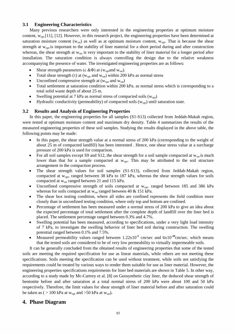
3.2 Results and Analysis of Engineering Properties
In this paper, the engineering properties for all samples (S1-S13) collected from Jeddah-Makah region,
were tested at optimum moisture content and maximum dry density. Table 4 summarizes the results of the
measured engineering properties of these soil samples. Studying the results displayed in the above table, the
following points may be made:
In this paper, the shear strength value at a normal stress of 200 kPa (corresponding to the weight of
about 25 m of compacted landfill) has been interested . Hence, one shear stress value at a surcharge
pressure of 200 kPa is used for comparison.
For all soil samples except S9 and S12, the shear strength for a soil sample compacted at wsat is much
lower than that for a sample compacted at wopt. This may be attributed to the soil structure
arrangement in the compaction process.
The shear strength values for soil samples (S1-S13), collected from Jeddah-Makah region,
compacted at wopt, ranged between 38 kPa to 187 kPa, whereas the shear strength values for soils
compacted at wsat ranged between 21 and 115 kPa.
Unconfined compressive strength of soils compacted at wopt. ranged between 185 and 386 kPa
whereas for soils compacted at wsat ranged between 40 & 151 kPa.
The shear box testing condition, where all sides are confined represents the field condition more
closely than in unconfined testing condition, where only top and bottom are confined.
Percentage of settlement has been measured under a normal stress of 200 kPa to give an idea about
the expected percentage of total settlement after the complete depth of landfill over the liner bed is
placed. The settlement percentage ranged between 0.3% and 4.7%.
Swelling potential has been measured, according to specifications, under a very light load intensity
of 7 kPa, to investigate the swelling behavior of liner bed soil during construction. The swelling
potential ranged between 0.1% and 7.5%.
Measured permeability values ranged between 1.22x10⁻⁵
cm/sec and 6x10⁻¹⁰
cm/sec. which means
that the tested soils are considered to be of very low permeability to virtually impermeable soils.
It can be generally concluded from the obtained results of engineering properties that some of the tested
soils are meeting the required specification for use as linear materials, while others are not meeting these
specifications. Soils meeting the specification can be used without treatment, while soils not satisfying the
requirements could be treated by various ways to render them suitable for use as liner material. However, the
engineering properties specifications requirements for liner bed materials are shown in Table 5. In other way,
according to a study made by Mc-Cartrey et al. [8] on Geosynthetic clay liner, the deduced shear strength of
bentonite before and after saturation at a total normal stress of 200 kPa were about 100 and 50 kPa
respectively. Therefore, the limit values for shear strength of liner material before and after saturation could
be taken as ( > 100 kPa at wopt and >50 kPa at wsat).
4. Phase Diagram
85

The “Phase Diagram” is constructed to show if a soil sample satisfies both, one or none of the two
requirements of liner-bed material specifications. In this diagram two limit lines are constructed. The first
limit is for permeability coefficient (k) which must be less than 1*10-7
cm/sec (according to liner
specifications, Table 5). The second limit is for shear strength at saturation (
than 50 kPa8. In The "Phase Diagram" (Fig. 3), the soil sample is represented by a point; the co-ordinates of
this point are the permeability coefficient and shear strength values. The two limit lines divide the phase
diagram into four quadrants, the first represents an area where both requirements are satisfied, the second
represents an area where permeability requirement only is satisfied, the third represents an area where none
of the requirements is satisfied, the fourth represents an area where shear strength requirement only is
satisfied. All soil samples are represented in one Figure showing the overall situation of these soils from a
point of view of suitability as liner-bed material.
Table 4: Engineering properties of studied soil
Eng. PP S1 S2 S3 S4 S5 S6 S7 S8 S9 S10 S11 S12 S13
w opt. stand. % 17.0 16.2 24.0 19.0 27.0 15.7 15.8 22.0 14.8 15.4 17.8 14.5 12.0
d max kN/m3 17.8 17.3 14.7 15.0 15.3 18.5 17.6 14.4 18.8 18.5 17.6 17.8 18.2
UCS (wopt. )
kPa 353 336 386 295 206 315 240 334 245 244 203 320 311
UC (wSat.) kpa 51.0 57.0 62.0 76.0 43.0 45.0 40.0 151.0 59.0 50.0 62.0 106.0 72.0
C (wopt.)kPa 63.0 20.0 13.0 138.0 101.0 12.0 21.0 127.0 8.0 148.0 90.0 24.0 44.0
Φ° (wopt. ) 11.0 18.0 26.0 6.0 12.0 12.0 8.0 11.0 10.0 11.0 13.0 4.0 18.0
kPa 101.9 85.0 110.6 159.0 143.5 54.5 49.1 165.9 43.3 186.9 136.2 38.0 109.0
C (wsat.)kPa 24.0 3.0 10.0 23.0 11.0 20.0 19.0 24.0 89.0 23.0 24.0 65.0 24.0
Φ° (wsapt. ) 8.0 11.0 6.0 6.0 3.0 4.0 5.0 10.0 5.0 10.0 9.0 14.0 5.0
(wsat.)
kPa 52.1 41.9 31.0 44.0 21.5 34.0 36.5 59.3 106.5 58.3 55.7 114.9 41.5
swelling
potential % 0.1 0.43 3.3 7.3 1.58 1.73 0.66 1.32 0.75 2.43 7.25 6.65 2.35
Settlement % -2.13 -2.49 -3.12 -0.30 -1.65 -4.10 -1.53 -4.70 -1.48 -1.48 -4.50 -3.44 -1.61
Permeability
k x 10-5
cm/sec
1.22E-
05
7.44E-
06
7.21E-
06
7.20E-
07
1.14E-
04
6.70E-
07
5.00E-
08
1.00E-
07
1.00E-
07
1.33E-
06
6.00E-
10
9.00E-
08
1.00E-
07
Table 5: Engineering characteristics specification requirement for a liner material[13],[14],[15]
Properties General requirements
Hydraulic conductivity (permeability) <1x10⁻⁷ cm/sec
Angle of internal friction at optimum moisture content- Wopt. > 20°
Cohesion at saturation moisture content- Wopt. > 2.5 kPa
Unconfined compressive strength at Wopt. >200 kPa
Total Settlement < 4%
Liner Thickness
installed in (15-cm) lifts > (75-100) cm
Minimal shrinkage potential to minimize desiccation and cracking
86
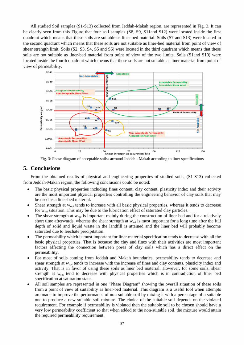
All studied Soil samples (S1-S13) collected from Jeddah-Makah region, are represented in Fig. 3. It can
be clearly seen from this Figure that four soil samples (S8, S9, S11and S12) were located inside the first
quadrant which means that these soils are suitable as liner-bed material. Soils (S7 and S13) were located in
the second quadrant which means that these soils are not suitable as liner-bed material from point of view of
shear strength limit. Soils (S2, S3, S4, S5 and S6) were located in the third quadrant which means that these
soils are not suitable as liner-bed material from point of view of the two limits. Soils (S1and S10) were
located inside the fourth quadrant which means that these soils are not suitable as liner material from point of
view of permeability.
1E-11
1E-10
1E-09
1E-08
1E-07
1E-06
1E-05
0.0001
0.001
0 25 50 75 100 125 150
Perm
eabi
lity
cm
/se
c
Shear Strength at saturation kPa
S11
S6S4
S3S5
S7 S13
S10
S8 S12
S2
S9
S1
Acceptable PermeabilityAcceptable Shear Wsat
Non- Acceptable PermeabilityAcceptable Shear Wsat
Acceptable PermeabilityAcceptable Shear Wsat
Acceptable PermeabilityNon-Acceptable Shear Wsat
Limit of Pemeability
Lim
it of
She
ar S
tren
gth
Acc
epta
ble
Non
-Acc
epta
ble
AcceptableNon-Acceptable
Fig. 3: Phase diagram of acceptable soilss arround Jeddah - Makah according to liner specifications
5. Conclusions
From the obtained results of physical and engineering properties of studied soils, (S1-S13) collected
from Jeddah-Makah region, the following conclusions could be noted:
The basic physical properties including fines content, clay content, plasticity index and their activity
are the most important physical properties controlling the engineering behavior of clay soils that may
be used as a liner-bed material.
Shear strength at wopt tends to increase with all basic physical properties, whereas it tends to decrease
for wsat situation. This may be due to the lubrication effect of saturated clay particles.
The shear strength at wopt is important mainly during the construction of liner bed and for a relatively
short time afterwards, whereas the shear strength at wsat is most important for a long time after the full
depth of solid and liquid waste in the landfill is attained and the liner bed will probably become
saturated due to leechate precipitation.
The permeability which is most important for liner material specification tends to decrease with all the
basic physical properties. That is because the clay and fines with their activities are most important
factors affecting the connection between pores of clay soils which has a direct effect on the
permeability.
For most of soils coming from Jeddah and Makah boundaries, permeability tends to decrease and
shear strength at wopt tends to increase with the increase of fines and clay contents, plasticity index and
activity. That is in favor of using these soils as liner bed material. However, for some soils, shear
strength at wsat tend to decrease with physical properties which is in contradiction of liner bed
specification at saturation state.
All soil samples are represented in one "Phase Diagram" showing the overall situation of these soils
from a point of view of suitability as liner-bed material. This diagram is a useful tool when attempts
are made to improve the performance of non-suitable soil by mixing it with a percentage of a suitable
one to produce a new suitable soil mixture. The choice of the suitable soil depends on the violated
requirement. For example if permeability is violated then the suitable soil to be chosen should have a
very low permeability coefficient so that when added to the non-suitable soil, the mixture would attain
the required permeability requirement.
87
6. Acknowledgements
The authors wish to express their sincere gratitude and utmost appreciation to King Abdulaziz City for
Science and Technology (KACST) for supporting this research project under great number "AT 30-32". The
investigators wish to acknowledge University Vice Presidency as well as Vice Presidency for Graduate
Studies and Scientific Research and the Deanship of Scientific Research of King Abdulaziz University for
their academic and material support for this study. The Faculty of Engineering and Earth Sciences, King
Abdulaziz University supplied logistics of fieldwork and allowed the research team to use the civil
engineering department equipment and facilities. Their generous support is gratefully acknowledged.
7. References
[1] AFED, Arab Forum for Environment and Development (AFED),. The 2011 report targets eight economic sectors
where "Green" transitions are anticipated, Case studies, with stories of successes and failures, are highlighted to
disseminate learning, http://www.afedonline.org.
[2] SAPME, Saudi Arabian Presidency of Meteorology and Environment (PME)., Saudi Arabia Environment, Health
& Safety Profile and Checklist May 2014 Prepared by The Isosceles Group 50 Congress Street, Boston,MA02109,
http://nimonik.com/case_studies/audit_previews/ksa_audit_preview_health_safety_environmentpdf.
[3] GCC, Arab Gulf Cooperation Council, Countries and their Role in the Protection of Environment and Preservation
of its Natural Resources. General Conditions of Contract for Construction Work, 2004.
[4] WQPN27 " Water quality protection note 27". Liners for containing pollutants, using engineered soils Government
of Western Australia- Manager, Water Source Protection Planning Department of Water , August 2013,pp14 -
This publication is available online at <www.water.wa.gov.au> select Publications > find a publication > series
browse > water quality protection notes. For those with special needs it can be made available in alternative
formats such as audio, large print, or Braille.
[5] EPA (U.S. Environmental Protection Agency), Solid Waste and Emergency Response (5306P), Washington, DC
20460, 2011, EPA-530-F-11-005 www.epa.gov/wastes.
[6] EPA (U.S. Environmental Protection Agency), Notification of Consultation and Coordination on “The
Environmental Protection Agency-Wide Plan to Provide Solid Waste Management Capacity Assistance to Tribes”.
User’s Guide. Office of Solid Waste and Emergency and Remedial response, Washington D.C.20460, 2010,
http://www.epa.gov/oig/reports/2011/20110321-11-P-0171.pdf.
[7] ASTM, Annual Book of ASTM Standards Specifications, American Society for Testing and Materials,
Philadelphia, PA, 2011.
[8] J.S.McCartney, J.G.Zornberg and R Swan. Internal and Interface Shear Strength of Geosynthetic Clay Liners,
(GCLs). Geotechnical Research Report, Department of Civil, Environmental and Architectural Engineering,
University of Colorado at Boulder, 2002, 471 p.
[9] A. A. Mesaed, R. J. Taj,. and H. Harbi. Stratigraphic Setting, Facies Types, Depositional Environments and
Mechanism of Formation of the Ash Shumaysi ironstones, Wadi Ash Shumaysi, Jeddah District, West Central
Saudi Arabia. Arab. J. Geosci. 2013(6): 2013-2033.
[10] BS1, Methods of Testing Soils for Civil Engineering Purposes. British Standards Institution: London, UK.
[11] R.K.Rowe. Systems engineering: The design and operation of municipal solid waste landfills to minimize
contamination of groundwater, Geosynthetics International, 2011, 16(6): 391-404.
[12] F.M. Francisca, D.A. Glatstein. Long term hydraulic conductivity of compacted soils permeated with landfill
leachate. Applied Clay Science, 2010, 49(3): 187–193.
[13] ] F.M. Francisca, D.A. Glatstein. Long term hydraulic conductivity of compacted soils permeated with landfill
leachate. Applied Clay Science, 2010, 49(3): 187–193.
[14] R. P. Chapuis. Predicting the saturated hydraulic conductivity of soils: a review, B. Engineering Geology and the
Environment, 2012, 71(3): 401-434. http://link.springer.com/article/10.1007/s10064-012-0418-7.
[15] AASHTO, Standard Specifications for Transportation Materials and Methods of Sampling and Testing. American
Association for State Highway and Transportation Officials: Washington, D.C.
88