uting frequency of an oscillator triode - … bound... · the lil\uting frequency of an oscillator...
TRANSCRIPT

r' ,.
"
'. .,;,
:1. ~- ,• :
'"
,' ...
• .it, I')'
Ti 12.9 r
,.'\ ,. -
, ,....Philips Rès. Rep, 5, 46-77: -1950.
THE LIl\UTING FREQUENCYOF AN OSCILLATOR TRIODE
\ by K. RODENHUIS 621.396.615
.f
Summary
This paper discusses the theoretical evaluation of the "limiting,frequency", that is, the highest frequency at which a triode is capableof oscillating, ' - ... ,A triode is considered as a four-pole. Inpart (A) general conditionsare derived that must be satisfied by the four-pole, coefficients inorder that 'a four-pole shall he able to deliver power into an externalcircuit; these are then identified with the conditions that a triodehas to satisfy to be able to oscillate.' In part (B) the relations
A existing lietween the four-pole coefficients of a triode on the one. hand, and the properties of the electron current, the series resist-'ances in the electrode leads, the resistance. of the emissive coating,and the dielectric losses in the insulators on the other hand, are. established and discussed. Finally in part (C) the theory is appliedto the ultra-short-wave oscillator-triode EC 81 where the calculatedlimiting frequency IS found to he 15% in excess of the limitingfrequency observed. This discrepancy can be attributed to theapproximations in the theory. The relative importance of variousfactors is clearly brought out by the. calculations. In a concludingsection. the experimental determination of the limiting frequencyis briefly describe~.
Résumé
Cet article discute l'estimation théorique de la "fréquence limite",c'est à dire de la' fréquence la plus ëlevëe à laquelle une triode estsusceptible d'osciller. ,Une triode est considérée comme un quadripêle, Dans Ja partie (A),on ëtahlirIès conditions générales qui doivent être satisfaites parles coefficients du quadripêle pour que ce dernier puisse fournierde la .puissance à un circuit extérieur; celles-ei sont identifiêes avecles conditions d'oscillation d'une triode. Dans la partie (B), on établitet discute les relations existant entre les coefficients d'une triodeconsidérée comme quadripêle, et les propriëtës du courant électro-nique, les rësistances sërie dans les conducteurs des ëlectrodes, larésistance de la couèhe émissive et les pertes diëlectriques des isolants.Enfin, dans la partie (C), la thëorie est appliquëe à la triode oscillatricepour ondes ultra-courtes EC 81, la fréquence limite estimée étantde 15 % plus élevée que la fréquence limite observëe, Cet écart peutêtre dû aux approximations faites dans l'étude théorique. Le calculmontre clairement l'importance relative des diffërents facteurs.Comme conclusion, on dëcrit rapidement la dëtermination expëri-mentale de la fréquence limite.
Zusammenfassung
Diese Ahhandlung diskutiert die theoretische Ermittlung der "Grenz-frequenz", . d.i. der höchsten Frequenz, bei der eine Triode zuschwingen vermag. .Eine triode wird : als ein Vierpol aufgefaBt. In Teil (A) werdenallgemeine Bedingungen abgeleitet, denen die Vi!lrpolkoeffizientengenügen müssen, damit ein Vierpol imstande ist an einen äu13eren
'.
'.

"'''', . ; ,
. ",,' ",. I .. I·tI ,,. ....
\'''- .. ," ,LTIlUTING FREQUENCY OF OSCILLATOR. TRIODE ., "'. 47
,, Strom:kreis Energie abzugeben; diese Bedingungen werden dannmit jenen für die Schwingungsfähigkeit einer Triode' identifiziert.In Teil (B) werden die Beziehungen, welche zwischen den Vierpol-koeffizienten einer Triode einerseits und den Eigenschaften desElektronenstromes, der Serienwiderstände in den Elektroden-zuführungen, ,des Widerstandes der Emissionsschicht und derdielektrischen Verluste in den Isolatoren andererseits bestehen,aufgezeigt und erörtert. SchlieBlichwird in Teil (C) die Theorie aufdie Ultrakurzwellen-Oszillatortriode EC 81 angcwendet; wobei eineurn 15% höhere Grenzfrequenz errechnet wird 'als die beobachteteFrequenz. Diese Diskrepanz ist den in der Theorie eingeschlossenenNäherungen 'zuzuschreiben. Die Wichtigkeit verschiedener Faktorenkommt durch die Berechnungen deutlich zum Ausdruck. In einem
I zusammenfassenden Ahschnittwird die experimentelle Bestimmungder Grenzfrequenz .kurz beschrieben. ' - .
,; .
"
Contents1. Introduetion
A. The conditions of oscillation
2: The active four-pole3. Application to; a triode4. The oscillator circuit
, ,
B. The, computation 'of the limiting frequency of ~n oscillator ~iode
'5. Method of computation6.' The properties of the electron current7. The losses in the electrode leads8. The losses in the "emissive coating9. Dielectric ló'sses '
",_ ..........
. ,
, , C. Practical application to the oscillator triode EC 81,J l
10. ,The oscillator triode EC 8111. Evaluation of the transit-time effects in the EC 8112. Evaluation of the losses in the leads of the EC '81
,, 13.. Evaluation of the losses in the emissive coating of the EC 8114. The limiting frequency of the EC 8~ , '15. Thè experimental determination of the limiting frequency
r : ,-
,.'-."'"
,1. Introduction
Both designers and users of oscillating triodes intended 'for use on, decimetric .or centimetric wavelengths are frequently faced with the',problem as to what factors determine the "limiting frequency" , that is, the 'highest frequency at which the tube is capable of oscillating. This problemwill be discussed below under the assumption that the limiting frequency
,\.- .-,
"
,\ ..'. "
.48 K. RODENHUIS
"
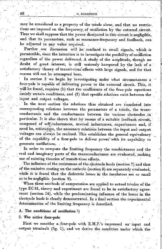
may he considered as a property of the triode alone, and that no restric-tions are imposed on the 'frequency, of oscillation by the extern al ,circuit.Thus we shall suppose that the power 'dissipated in this circuit is negligible,and 'that its parameters, such as resonance-frequency and feedback, canhe adjusted to ~my value required. .
Further ,our discussion will be'. confined to small signals, w_hich is'permissible, since the intention is to investigate the posibility of oscillationregardless of the power delivered. A study of the amplitude, though no
,.' doubt of great, interest, is still seriously hampered by the lack of asatisfactory theory of transit-time' effects with large signals; and for thatreason will not he attempted here ..
In section 2 we begin by investigating under what circumstances a .four-pole is capable of delivering power to the external circuit. This, it. will he found, requires (1) that the coefficients of the four-pole equations~atisfy ce~tain conditions, and (2) that specific relations exist between the
. . input and output voltages. ' -, . In the next section the relations thus obtained are t~arislated into'.~ .~. ,.corresponding relations between the parameters of a triode, the trans-cönductanée and the conductances between the various electrodes. in .partienlar. It is also shown that by means of a suitable feedback circuit,composed .of aelf-inductances, mutual inductances, capacitances and, ifneed be, r~slsta~~9fs,the necessary relations between the input and outputvoltages can alwäys he realized. This establishes the general equivalencyof the capability of a four-pole to deliver power \with its, capahility togenerate oscillations, ,- In order to compute the limiting frequency the conductances and thereal and imaginary parts of the transconductance are evaluated, ,makinguse of existing theories of transit-time effects.
The influénce ofthe resistances ofthe electrode leads (section 7) and thatof the emissive coating on the cathode (section 8) are separately evaluated,while it is found that the dielectric losses in the insulators are so smallas to he negligible (section 9). .When these methods of computation are applied to actual trio des of the . .
\ type EC 81, theory and' experiment are found to be in satisfactory agree-ment (section 14), while the predominating influence of the losses in theelectrode leads is clearly demonstrated. In a final section the experimentaldetermination of the limiting frequency is described.
A: The conditions of oscillation 1)2. The active four-pole
First we consider a, four-pole with KM.F.'s impressed on' input and'output ,terminals (fig. I), 'and we derive the condition under which the
.~.
J'
) .

~ 'V V * [A + A * ~(U ,+a*)2' (a - a*)2( (D + D*), 1 1 2 + ( 2 + 2j ~ ,2 +, .o: + a* (B + B*. C + C*)__:a -' a* (B-B* C-C*)].+ 2 2 + 2 '2j 2j, 2j
(4)
, ", \'
LIMITING FREQUENCY' OF 9sciLLATOR TRIODE ',49
power absorbed by this four-pole becomes negative;' or, what comes tothe same. thing, the conditions under which the four-pole will supply
I. power, to the external circuits. If the four-pole equations' are
11= AV1 +.BV2,
12 = CVI + D V2 ,
the average power absorbed by the four-pole will be *)
. p _ V1I1*+ VI*II V2I2* + V2*I2- 2 + 2 '
(I) -,
(2)
where VI*, 11*, V2*. and 12* denote the conjugate-complex values toVI,II, V2, and 12,respectively. After eliminating 11, 11*, 12, 12*with theaid of equations (1) we obtain
p,- i lVIV1*(A+A*) +.V2V2*(D+D*) +VIV2*(B*+C) +V1*V2(B+C*)~ (3)
which by writingV2 '
a = -·and a*V .1
is transformed into
With the notation
A +A*2 = a;
D +D*----=b;2 , .1
B + B* C + C*2 + 2 = C;
B-B*2j
C-C*----d·2j - , (5)
a + a* a - a*2 ' =X; ~2-']-·- = y;
this reduces further to
p = V1VI* la + (x2+ y2) b + xc-yd~.,(6)
• .... J ,
. Vm '( 1+ ) , '1m i( 1+ } ,*) Ifwe have V1 = -;= eJ W rp, 11= -.-=- e W lp (Vm and 1m real) rt follows thatr2 l2 ' I
V 1 * +' V *1 v: 1 cj(q;-lp}+ c-i(q;-tp} ,v. 111 11 mm mm ( ). 2 = -2- 2' = -2-cOS q>-lp ,
which is the average power supplied to the I?rimary terminals,
I'
, ,
"
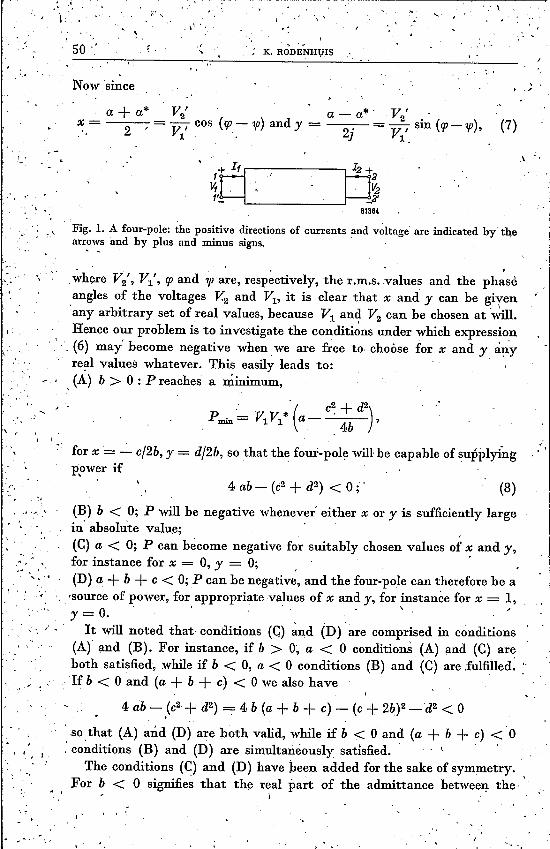
.. ,~here V2', VI" cp and 1pare, respectively, the r.m.s. values and the phaseangles of the voltages v'2 and Vl, it is clear that x and y can be given, . \
any arbitrary set of real values, because Vl an~ V2 can be chosen at will.Hence our problem is to investigate the conditions under which expression
'. . (6) may' become negative when we are free to choose for x and y arryreal values whatever. This easily leads to:
"" . ,(A) b > 0 : P reaches a minimum,
,1_'
,.'
v , -I
, .Ó, " ,
,.....->. ~ ..
, I
.\"
..i ~ • r
i I \"
;\\ ",. , - .... '\,
. 50·l .r... K. RODENHVIS
.Now since
I. '
a + a* V2'. • a - a*' V2' .x= '=-V,cos(cp-1jJ)andy= . =-,sin(cp-1p), (7),'. 2 l. 2] Vl.
1+rc==p1f .' ' 12+2
t.1" . ,~1'_ ,_2'
61384
Fig. LA four-pole: the positive directions of currents and voltage are indicated by thearrows and by plus and minus signs.' .. -
, I
*'( c~+ d2). Pmm = VlVl a - . 4b '
for x ' ~ c/2b, y = d/2b, so that the four-pole will be capable of supplyingppwer if
"
4 ab- (c2 + d2) < 0;' (8)"
(B) b < 0; P will be negative whenever either x or y is sufficiently largein' absolute value; ,(C) a < 0; P can bècome negative for suitably chosen values of x and y,for instance for x = 0, y = 0; , .(D) a + b + c < 0; P can be negative, and the four-pole can therefore be a'source of power, for appropriate values of x and y, for instance for x = 1,r = 0.' . \
It will noted that- conditions (C) ~nd (D) are comprised in conditions(Ar and (B). For instance, if b > 0; a < 0 conditioris (A) and (C) areboth satisfied, while if b < 0, a < 0 conditions (B) and (C) are fulfilled. :'If b < 0 and (a + b + c) < 0 we also have
4 ab '- ,(c2 + d2) . 4 b (a + b + c) - (c + 2~)2 - d2 < 0
, so that (A) and (D) are both valid, while if b < 0 and (a + b +c) <0: conditions (B) and (D) are simultanèously satisfied. . t "
The conditions (C) and (D) have heen added for the sake of symmetry.For b < 0 signifies that the real part of the admittance between the
" \ \
, 'I

~----7'
I, .'
' •• 1-
1.-,'-. \,
,:"" ,~ .,: "-v
" • . , '. . LIMITING FREQUE~CY 0,]' OSCILLATOR TRIODE ~ , " 51.~~,~~ ~~~ ~~~ ~ ~ 7~---..terminals 2 and 2' is, negative when the terminals 1 and l' are' short" t
circuited;' and a < 0 likewise denotes that the real part of the admittancebetween: 1 and l' is negative ~....hen 2 and 2' are short-circuited; lastly, I••
(a + b,+ c) < 0 means that the real part of the admittance. between1 and I' or 2 and 2: is negative when 1 has heen connected to 2 and I', .to .2'. This last condition will hold good in par'ticula'r w~en I' and 2' are '. "-internally short-circuited, ai? is the' case in the triodes with which thispaper is concerned.
To sum up we may cÓnclude that a four-pole may. be a source of power'when the. coefficients of the four-pole equations
11= AV1 + BV2
12= CV1 + DV2
(1)
satisfy, one of the foll?wing four conditionsf
4 (A+A*)(D+D*) _~(B + B*+ C+ C*)2+ (B-,B* _ C_:_.C*)2~=,2 2 (2' 2 \ 2] 2J" ~4 Rè(A) Re(D) - J}Ré(B + CH2 + ~Im(È - C)~2]< 0; . (9a).
." ,-' ~.D+D* .
. 2 = Re(D) <, 0 ; " (9b)
, \
A+4*---= Re(A) < 0;
2(9c)
A + A* D + D* . B + B* C+ C*, +_._._+ + =Re(A+B+C+D)<O .. (9d)2 2 2 . 2'
-i '\
3. ,App~cation to a 'triode
If in a triode the input terminals are the cathode and the 'grid, and the,output terminals the. cathode and the anode (grounded-cathode circuit,see fig, 2) the four-pole equations' read I
,. j'
"'
Gak
(S+jZ) Vt
"
V,
60'6)
Fig. 2:Circuit diagram of a triode in grounded-cathode arrangement., .,
e .

(12a)
, 52;' K. iWDEN~UIS
11= V1(Gag + Ggk + jBag + jBgk) + V2(- Gag - jBag) , (Iüa) '.
12 = V1(1~ - Gag + jz - jBag) + V2(Gag + Gak + jBag + jBak), (lOb)
where G and B denote respectively the real and the imaginary part of theadmittance between the electrodes, and sand z the real and the imaginarypart of the tran~conductance. .If we take cathode and grid. for input, and grid and anode for output
(grounded-grid circuit, see fig. 3) we 'have instead .. I
11= V1(s + Gak+ Ggk +"jz + jBàk + jBgk) + V2(- Gak -jIJak) , (lla)
J2 = V1(- S - Gak - jz,- jBak) + V2(Gag + Gak +jBag + jBak),' (llb)
iIi·
Gak
60186
Fig. 3. Circuit diagram of a triode in grounded-grid arrangement.
while if we use anode and grid. as input, and ano'de and cathode as outputterminals (grounded-anode circuit, see fig. 4) we have: .
!2= V1(..L S - Ggk - jz - jBgk) + V2(s + Gak + Ggk +j~+jBak +jBgk)., .(12b)
Ggk
+ 11
, "
Fig. 4,. Circuit diagram of a triode in grounded-anode arrangement.

LIMITING FREQUENCY OF OSCILLATOR TRIODE 53.
, "
" ,",
If we now apply conditions (9) we find that in .each of these three setsof equations the same set ,of conditions háve to be satisfied by the variousconst~nts occurring in them, namely,
4 (Gag + Ggk) (Gag + Gak) - ~(s - 2'Gag)2 + Z2~ < 0,s + Gag + Ggk < 0,
Gag + Ggk < 0,Gag + Gak < O.
- (l3a)(13b)(13c)(13d)
, \
, That this should be so is almost self-evident, for a triode is a three-pole,, so that' if two voltages' are known the third will also be fixed, andif two of the currents are 'given the third will be fixed. Whenever sucha three-pole can be a source of power it wi]l he quite immaterial fromwhich set of voltages we start in proving this fact:
\
. 4. The oscillator circuit .
When a triode forms part of an oscillator circuit the input.' and outputterminals will be connected to an external network comprising the feed-back and the load, that is, the circuit element which dissipates the power'supplied (fig. 5)._
feedbacknetwork
"
/
triode
Fig. 5. Triode four-pole and feedback four-pole co~bined.
Whatever the actual compositîon of the feedback circuit may be, it canalways' in a 'general way be represented as a four-pole with equations ,
lOl = Ao VI' + s,V2•
102 = COVI + DOV2,
, (14a)
(14b)
while the triode and the feedback circuit together can be considered as.another four-pole, the equations of which will be written as
where
11' = A'VI + B'V2,
. 12' = C'VI + D'V2,
11' = 11+ lOl " 12' = 12 + 102
(15a)
(15b)
(16)1.
and A'=A+Ao, B'=B+Bo, C'=C!+ Co, D'=D+Do'
. :/

, I,I"
I' , .1 , "
54._ ,
K, RODENHUIS '.. "~, '
We now proceed to show that' the ratio required between. th~ voltages . -V1 and V2 in' order that a four-pole can be a source of power can actually'be satisfied by means of the feedback circuit, which proves that the con-dition of power supply is equivalent to the, c~n?ition of oscillation, :When the load and all the other external circuit elements are considered
, \
I '
", as part of a single four-pole the current 11'and 12' in fig. 5 must clearly -'be zero, while under oscillating conditions the input and output voltages, will possess certain definite values. From 12' = 0 we deduce by (ISb)
0= C'+ (x + jy) D', (17)
, '
where T!2/V1 , a,= x + jy. This may be split up into
C' +C'* D' + D'* D' _: D'* , '2 +x 2 -y~-=o,
, ,
B'-B'*d' _;_----
C'-C'*(20)
(18a)
I,and
C'.:__ C'* D' - D'*, D +"D'* _2j +x~-+y 2 =0, (18b)
"~quations that can he fulfilled for any set of values of x and y by assigningsuitable values to the imaginary parts of the four-pole coefficients.Now, if the feedback circuit is composed of resistances, capacitances,I self-inductances and mutual inductances, the only condition to he fulfilledis Bo = Co, so that ithree of the four coefficients can be chosen at will.This means that we can also assign any values we choose to the imaginary'parts of three of the coefficients of the combined four-pole. Consèquentlyit is always possible to' satisfy equations '(18a) and (18b).'
We proceed to investigate the consequences of the condition 11' O.Since V2/V1 _:_ a = x + jy eq. (ISa) gives
., .. ~'+A'* ,B'+B'* B'-B'* ,(A'-A;* . B-B'* 'B'+B'*)l,11= V~t--:-,-2--+x 2 -y 2j +J 2J-+~~-+y 2 ~.
, (19)fWriting in analogy to (S)
"
" .','
'"
"
A'+A'*a'=----
'2
B' + B'* C''+ C'*,c' = 2 +--2--;
, D'+D'*.b =----,2
" '
2j 2j
\ve, findby eliminating (D' --D'*)/2j from equations (18a) and (18b), ,
B' + B'* B' - B'*'· 'x - y , = (x2 + y2) b' + xc' - yd' ,2 ~ . (21) . '
\\
J,

. .' ~.''_; .••.•. "1 I I ' .
,. ~~,• ~• • r • !'
~- .___: .
'~ .' ~ LIûITiim FREQUENèi.OF OSCILLATOR TRIOD'E, . ,
" I 55
, .
,' and by introducing this. in '(19) we are led to ,
t.: _ ••. '. '(AI-À'* ' B'-B'*' BI+B'*)~ -:-.,.~ = t:+ (X2+y2) b'+ xc'=' +j 2j +,x 2j , + y 2 .~. (22) .
The imaginary part of I1'/V1 can be made zero by adjusting the value of ' ".(A' - A'*)J2j: ' I , • '
,Thè conditions under which the real part of (22) equals zero require amore detailed investigation. For that' purpose we write'·
, I
..~,
a' = a + ao; b' = b + bo ; c' = c = co; d' = d + 'do,
Ao + Ao*;ao.= 2 '
B~+ Bo * Co + Co*c - + .0- 2 -, -2---'
which gives
D +D*-b _ 0 o.0- 2d _ Bo~Bo*0- 2j
~ I,' ,;
I " ~"
The second polynomial in x and y on the right-hand side refers to tIle,triode; it is the same as encountered in the power consideration of section ,2, and, as shown there, this expression can be negative for suitably chosen .,' 'values of x and y and must be negative if the tziode is 11'source of power. 'The first polynomial is of the samé form, but refers to the feedbackcircuit; and since this is a passive circuit, incapable of delivering pO,wer,this -expression must always be positive, \
Summing up, we have found that the conditions Il' = 0, and 12" = 0can he simultaneously satisfied by a suitable choice of (D - D*)j2j,_(C-C*)j-2j and (A-A*)j2jfor such values of x andy, orof V2/V1;forwhich
ao + (X2+ y2) bo + xCo .:__ydo = a + (x2 +y2) b + xc - yd.
, I
'J '.
, ,
, '
This last equation can be fu:lfilledby fixing the real parts of the coefficientsof the feedback four-pole in an appropriate manner. This proves that'-the condition the triode has to satisfy to be a source of power is equivalent .to the condition it has to satisfy to be capable of oscillating.Hence equations (13a), (13b), (13c) and (13d) will briefly he called the."c~nditions of oscillation".' . •. "
I
B. The computation of the limiting frequency of an oscillatlng triode
5. Method or' computation
The, conductances between the various elect~odes 'and the ~eal and thejmag~ary part' of the transconductance enter into the conditions of
. /'
\ ,"

rI
I.III
j .
,',
"56 ' . K. RODENHUIS
oscillation, quantities that' are all functions of the frequency, In order to .calculate the limiting frequency, that is, the'highest frequency at whichthe conditions for oscillation can be satisfied, it will he necessary to knowthese various quantities as a function of the frequency. The functionalrelations will he determined by the following factors:. (a) the transit-time effects ofthe electronic current moving through the
space between the electrodes; .l
(b) losses in the resistances formed hy the leads connecting the electrodeswith the external circuit and resulting from the capacitive currentsHowing through these leads;
(c) the losses in the emissive coating of the cathode; and(d) dielectric losses in the insulators. ." In carrying out the computations it will be assumed that the conduct-ances between the different electrodes, due to the factors (a) to (d) listedabove, may simple he added to find the total conductance.As mentioned in the introduction, losses in the external circuit are ignored;
. that is t~ say, we assume that these losses are negligible compared to thelosses in the triode itself. Further it is worth noting that effects resulting from
. the self-inductance and mutual inductance of the leads are .alsodisregarded;they may he considered as forming part of the feedback circuit and assuch will have-no influence on the four-pole equation of the triode itself .., The method of computation, it is to he observed, is purely numerical.
.This has the disadvantage of involving some calculations, but it has theadvantage that we obtain a clearer picture of the relative importance ofthe various factors and thereby a' better insight into the conditionsprevailing in a triode oscillating at very high frequencies.
6: The properties of the electron current
Since we are considering high frequencies, transit-time effects' must he. jaken into account. To this end we shall make use of the existing theorywhich assumes:(1) that the electrons emerge from the cathode with zero velocity;(2) that the alternating currents and voltages are small compáred to thedirect currents and voltages; and .(3) that the control grid acts as a perfect electrostatic screen between the, anode and the cathode, possessing the average potential in the plane of thegrid, and through which the electrons can pass without the least hindrance. '" .Bakker and De Vries 2) .have developed formulae descrihing the case
depicted in fig. 6, where an electron current penetrates through such a~id into the space between grid and anode. As a consequence of theHuctuations in velocity and in density of this How of electrons a current .. will How through the anode lead which is given by
/

, i. ,.
. '.LIMITING FREQUENCY OF OSCILLATOR TRIODE 57~----~--~----~~--------------~~~~~,.
'whére10Id
-- the average current, ,-- the alternating-current component, .
the, average velocity of the electrons,the alteniating component of the velocity,
-- the transit-time between g and a;'= jare;, where ill is the ,angular frequency,=. the clearance hetween grid and anode
Va-- Vst
, ... "j
.e . = ,-' Vao -- Vsto .
e Vao -:- Vsto
d '-m 2
Va the alternating voltage on the anode,Va~ -- the direct voltage on the anode,Vst the alternating voltage of the hypothetical grid,Vsto the direct voltage of the hypothetical grid,e -- the eharge 'of the electron,m -- the mass of the electron,qJl(a)= I/a ~I-- exp (-- a)~, (25)ç{J3(a)= 2/a2 ~I-- (1 + a) exp (-- aH, (26)qJ4{a)= 6/a3 ~a -- 2 + (a + 2) exp (-- a)~. (27)Here, as elsewhere, in this paper, all quantities are expressed in ration-
alized Giorgi units. . .For the case depicted in fig. 7, Id and lT/l canbe calculated from formulae
developed by Zuhrt 3), namely, .
,'." .
y ,-,
• J
"
,(28)
d2,----r, 'ï++.!.It Iaa
- ~-v.t+ 60' ••
Fig. 6. The space between grid and anode in a triode."

, ., ~.
'.
"...~.. - \58. K. RODENHUis'
.. /.
'.- .(29)
I
withI SD VS!
, k = W6(al)''I(30)~
where al = jonl 'tI being the transit time between cathode and grid, ., dl '= the clearance between cathode and grid, and
4>6(~)' 12 ~a3_:_'(a-2) _ (a+2) e~p(-a)~,a4 (6 ~
4>3(a) and 4>4(a) being the functions given by (26) a~d (27).
r
t'
- Vst +
(31)
..!..I+.J..I+.i,II
g
Fig. 7. The space between grid and cathode in a triode., '
60300
- . ,
These formulae assume that the idealized grid, at an alternating voltageVS! with respect to the cathode, engenders an alternating current Id
, passing through the grid and a cath~de current Ik. At low frequency thiscathode current equals Ik- = SD VS!; SD may suitably be called the diode
, ' transconductance.,'_ The transit time~ 'tI and 't2 figuring in equations (24), (28), (29), and
. \. (30),. can be computed hy the equations
. '. 3dI'tI = , ,.I
. y~~VS!o
,i
_., .
(32),I
velocity of the electrons in the plane
. y2e;t-Jr/o = .,;_.y Vsto'm
.,t,
while the average'e
",
.:': ,I, ,
(33)
of the grid is
(34)

, . ~1 '
"
,( -'_ .f,'. • • _,
"I _, ",.;.' ~' _t 'i." r -', V,," .,.""'. ..:.
,,' :, -,' LI~llTING FREQUENÇY OF OSCILLATOR TRIODE
".... ,~.. .
'·1' ,, 'i . ',.
'-.'
• J • I , ,I , ", , "', , ",' '... :Lastly we 1:{av;e'to add the current flowing through the capacitor formed ,,'
by grid and anode owing to the alternating voltage between these twoelectrodes. This current is' - : . .. :.. ,',I,
59 ' , .
I= (Va - Vst) jwC, , (35)/
where the capacitance C is givèn byi
(36)
, 0 being the active surface area and EO the dielectric constant of the vacuousspace. Making use of the equations (32)~ (33) and (36) and of the relati~n. '
", . 2 4 " J/2e 0 ' ,,'SD = - . - 80 - - Vs!O "
. 3·9 . m, d12(37)
we may write \ ." '.~',"~
'.,;) J.'
(38). "
Adding (38) to (24), substituting (28), (29) and (30) in (24), and using,the relations '
(39) .
(~O) 'I
(41)
and
in which
:For the sake of simplicity we shall writ~ (30) and (42) in the form
Ik = VS! SD P,<t,,', .
(43)
(44) ..'
" . , ~ ,

"60 K. RÓDENHUIS
, ,The derivation of' these f~rmulae presupposes the grid to bOe,a perfect. electrostatic screen not hindering the ele'ctrons passing through it. In'actual triodes this is a satisfactory approximation provided the grid is
., sufficiently fine-meshed, and provided we take for, Vsto and Vst the averagepotentials in the plane of the grid;
V _ VgO+ DaVaoSlO - 1+ o; + Da (45)
and
Vg + DaVaVSI = i + Dk,+ Da'
where VgOand Vg are the direct and the alternating voltages on the griditself, Vao and Va the direct and alternating voltages on the anode, andDk and Da are the inverse amplification factors of cathode a~d anodewith respect to the grid. ' . .
From the fact that at low frequencies the alternating current in a
(46)
'. triode is.' Vg + DaVa.Ia = SD VSI = SD --_. ,
1+ Dk + n; (47)
it may he concluded that hetween the transcouductance of the triode and.the diode transconductance as defined by (30) the following rel~tion holds
SDSo= -'-----
1+ Dk + Da(48)
Consequently we arrive at- the following expressions for Ik and la:
ik = Vg soP + VasoDaP, (49)
la = VgsO(Q - R) + Vaso ~DaQ + (1+ Dk)R~ , (50)
while the equivalent circuit depicted in fig. 8 leads toI
Ik":'_ Vg(Ygk+ sa) + VaYak,la = Vg(- Yag +~a) + Va(Yag + Yak).
. (51)
'(52). .. The admittances and the transconductance defined by fig. 8 can now beexpressed in the quantities derived from transit-time theory in such a,"way that equations (51) and (52) become identical with (49) and (50):
I
(53) .
(54)(55)(56)
Sa= So ~Q - Da (P - Q) + DkR~, .Ygk = So~(1+ pa) (P- Q) - DkR~,. . ,
Yag = So~-.Da (P__:_Q) + DkR)~ ,
I.

6039'
Fig. 8. Equivalent circuit of a triode ,used for computing the admittances produced b~transit-time effects.
., .
I , UinTING FREQUENCY OF OSCILLA~OR TRIODE, ,
61.,.1
where
The contribution of the electron current to the quantities Ggk, Gag and Gakoccurring in thc conditions of oscillation are made up of the real parts oflTgk, Yag, and Yak- I \' • •
Ia ++
. 7. The losses in the electrode leads
As a consequence of the alternating voltages impressed on the electrodes;capacitive currents will flow through the leads connecting these electrodeswith the external circuit. Even though we are constantly striving tokeep the h.f. resistances of these leads as low as possible, they are at highfrequencies nevertheless of such importance as to determine largelytheoscillating capability of a' triode.
We recall that the skin-effect resistance of a c~lindrical conductor atvery high frequencies is
... ;
,,
2 I '
r = - l e,Lt!10-7 Q/md ,
(50)
where d is the diameter, e'the specific resistance, ,Lt the relative permeahilityv-and! the frequency. EVidently, materials with a low specific resistance~nd' a relative permeability ,Lt= 1 are to preferred (for example; copperor silver). It will also be .noted that the resistance is proportional to thesquare root of the frequency, supposing or' course that ft is frequency-in~w&~ .'.
, '.1.

, .
"
, 0
:r ,,_~ I ", .
.'.\
0'
," , 4""
0,
t
v ;"
. '. . 'J
, ,.
62 K. R,ODENHUI!:?'.\, .•..
The equivalent circuit of a triode is represented in fig. 9, where k, g,and à indicate cathode, grid and anode, respectively; Cag, Cgk and Cakare\ the ip.terelectrode capacitances, Ck, Cg and Ca the capacitances to '
. 'ear~h and Tk, Tg and Ta the lead resistances. ..This circuit is clearly an approximation, and that for two reasons.. In
the first place the capacitances and ~he resistances will not be concentrat~d, "but distributed properties of the .elect:rode system. However, the mainportions of the capacitances are formed by the interelectrode capacitances,and the main portion of tIle resi~tances resides in the electrode leads; sothat the circuit of fig. 9 may; from this point of view; be considered as asatisfactory approximation. '
Fig. 9. Equivalent circuit of a triode used for computing the conductances resultingfrom the resistances of the leads. .
.'.,
I.....
Secondly the interelectrode admittances are not purely capacitive;they possess, a real part owing to the electron current, while, moreover, acurrent SaVg is flowing through the cathode and anode leads. Inclusion
, ?f the losses resultmg from the electron current would, however, render. the formulae extremely. complicated without adding much to their preci-sion, because, at th~ high frequencies in which we are interested, the capa-citive currents are by fár the most important. '\ T~ express th~ influence ~f 'the ~esistances in terms of admittances we.first tansform the star circuit composed of the three to-earth oapacitances
, Ck, Cg and C(l into ~ delta circuit, which is then added to th~ delta circuitformed by the interelectrode capacitances (fig. 10). -The resultant total'delta capacitances are given by , ,
I CaCgCag = Cag + C C Ck. a+ g+, , ,
(61)

.' ,",\ , )-'
. )' \ \-
LIMITiNG FREqUENCY OF ,OSCILLATOR TRIODE'. , , \ 63
, .. and by two similar expressions 'obta{~ed by cyclical interchange of t~eindices a, g and k. ' , .
The' combined delta circuit is now once more transformed into a star. 'thus leading to the circuit of fig. 11.
,, ,
, .
~I '. - •
Fig. 10. Circuit obtained after the star circuit of the to-earth capacitances has been trans-formed into a delta circuit. '
The capacitances Cf., Cg and C~ are giv:en by
Ck' ~ C~kCgk + C~kC~g +,CgkC~gC' ', ag
and cyclical interchange. _Lastly the star circuit of fig. 11, with capacitances and resistances in'
series, is transformed into a delta circuit as in' fig. 12 with capacitances" 'and resistances in parallel. Assuming the. impedances of the capacitances .to, he large compared to those of the resistances (for example, .whenC= 2 pF and f= 1500 Mb/sec 'we have I/wC = 50 ohms, (against lead,
(
resistances that are usually of the order of 1 or 2 ohms) this requires
(62)
.'
G~g= TaW2 C~g(C~k+C~g) + TgW2 C~g(C~g+Cgk) _:_Tk2 C~kCgk; cycl~c. ,(63)
TInder these same conditions the capacitances of fig. 12 are practically,equal to the capacitances C~g,' Cgk and C~k in fig. 10. •,
I,
Fig. 11. The delta circuit of fig. 10 transformed into a star circuit. .: , . '

-,
Fig. 13. The equivalent circuit used to account for the emissive coating. This coating isrepresented as a resistance Tl in parallel with a capacitance Cl both beirig connected inseries with the. capacitance C2 between the outer surface of the oxide coating and the
\ ' grid. For a given frequency the influence of the resistance Tl can he represcnted by a'conductance G. (fig. l3b).
:
.-.,'
.1
, '
./, ,, .
I ,.64 ~
K. RODENHUIS
Here the influence of the series resistances has been' evaluated without·taking the external circuit into consideration. This -is correct only ifthe external circuit possess~s no impedances with respect to earth; for if.that were so, the triode could no longer be considered as a three-pole,.but should' be treated as a four-pole, the fourth pole being the earth., This would complicate matters. Since, however, in most cases the to-earth,capacitances are s~all compared ,~ith the interelectrode capacitances, theerror 'will be small.
Fig. 12. The star circuit of fig. 11 after transformation into a delta circuit in which theinfluence of the series resistances has been expressed in terms of conductances betweenthe electrodes.
8. The losses in the emissive coating
The emissive coating on a cathode, consistmg as a rule of barium-strontium oxide, possesses ä): its working temperature the character of adielectric with a relative dielectric constant of about 4, and a specificresistance of 3 Om, the latter, however, being strongly dependent on thefemperature.
Fig. 13 shows how the influence of the losses in the emissive coating on theconductance betwee~ cathode and grid may be accounted for. When an

',' 1"~I' ";'1 I ~ :"
" .1' ,
, ,~."LIlIIITING FREQUENCY OF OSCILLATOR TRIOpE
I "': ~. á.c, voltage, is applied .hetween grid and cathode a capacitive currentI will flow between the grid and the surface of the oxide layer this being'
passed on to the cathode itself via the capacitance Cl shunted by the 'resistance rr- Between g and k the total admittance will be '
y. _ jwC2 (l/rl'+ jwCl) "
e - I/rl + jwCl + jwC2 '
the real part of which is
9. Dielectric lossesI " *.
The dielectric losses are as-a rule so small that they can safely he ignored .., • • ,1
For instance, between the base pins. of grid and anode in the glass base of 'the EC 81 (a type of valve discussed in greater detail below) we observed' ,a conductance of less than 1 fLA/Vut a frequency ~f 300 Mc/sec, and theconductances resulting from the dielectric losses in the other insulators,such as the mica spacers, wil! he smaller still. Moreover, since tan (J ispractically independent of the frequency,'the conductances ofthis class areapproximately proportional to thefrequency, whereas the, conductances dueto the lead resistances are proportional to the 5/2 power of the frequency,, Hence, the higher the frequency, the smaller the relative importance of
• I '
the dielectric losses. '.' -' "
C. Practical application to the oscillator triode EC 81
10. The oscillator triode EC 81
.In the following sections the theory developed above will be applied _to the oscillator triode EC 81, ,a yalve illustrated in fig: 14.This valve has an all-glass envelope. The pins in rhe base are made of
copper-coated chrome-iron while the portion protruding on both sides of J
the glass of the base has an additional coating of silver. Thanks to these ..measure the high-frequency resistance of these pins is as low as that' of, .;pure copper, whil~ the. advantageous mechariical rigidity and thermal'expansion of chrome-iron are retained. Of the internal components, toot .'the high-frequency resistance has been kept at a very low lêvel, either' by .,'using highly conducting materialor Dy applying an electrolytic coating "of copper or silver. " , . ,', ,
:1'0 reduce the losses in the leads the interelectrode capacitances have;heen made as small as possible by reducing the size of the electrodes, as, ,'far as such was feasible in view of the power to he dissipated.
J' .' '
65
(64) .
(65)
,l
I',
, ,
"
"
'.

66 K. RODENHUIS
These various measures, in combination with a small clearance betweenthe various electrodes, have led to a valve of conventional constructionwhich nevertheless yields satisfactory results at frequencies considerablyhigher than 300 Mc/sec. This may be seen from fig. 15 representing theoutput and the efficiency as a function of the frequency according to theofficial data.
Fig. 14. The EC 81. Left, the valve complete; right, the electrode system and pressed-glass base.
To compute the limiting frequency we have to know the values of
Sa = S _,L jz, Gag' Gak, Ggk,where
Gag = Re(Yag} + G~g ,
Gak = Re(Yak} + G~k ,
Ggk = Re(Ygk} + G~k + Ge.
(66)
(67)
(68)
These values will be derived in the next sections.
11. Evaluation of the transit-time effects in the EC81
The transit-time effects will be evaluated for the case where the anodedissipation and the cathode current have reached their highest permissiblevalues, that is when
Wa = 5 W, 10 = 30 mA.

I' LIM~TIN~ FREQUENCY OF OSCILLATOR TRIODE
Under these circumftances the anode .voltage is 167 V, and the trans-conductance
SinceSo , 5'5 mA/V.
'Da ~ 0'062 and Dk = 0'184,
the diode, transconductance according to equation (48) is found to he- ,
SD = 6'85 mA/V,
while equation (39) yields the valueI
VS10 = 6'57 V
for the average direct voltage in the plane of the control grid.The clearances between cathode and grid and between grid and anode
are, respectively, 125!J. and 275 fJ., so that using the foregoing data we.obtain the transit times from equations (32) and (33) as
i, •.
<1= 2'47.10-10 sec, 1:2 = 0'60.10"'10Sec.I
The admittances Ygk, Yag, and Yak and the real .and imaginary parts 'ofthe mutual conductance can now he calculated at various frequenciesby means of equations (53) to (59), this yielding the results collectedin table 1. " , .
- '48 II.{".
Wo,w,· 'Ii (w) (%)Va 7,5 60
Ia
Tl
5 40
11.{,
Wo
2,5 20.,
19 -,
0 060 . 80 >..(cm) 100
. 600W!
300 30
~max -300Vw"max= 5Wkmax =30mA
200 20
100 10
o oo 20 40
- ,Fig. 15. The total input power, Wi, the power dissipated by the anode, Wa, the powerdelivered, Wo, the anode voltage, V~, the anode and grid currents, la and Ig, and the.efficiency, '1], all plotted as a function of the wavelength. At 20 cm (1500 Mc/sec) thepower de_liveredis 100 mW; at 1600 Mc/sec the oscillations cease altogether.
I,

, "
I,'
r
'"
,
,L 68I
, '
. ....~ ",I'
K,:nÓDENHUIS,
t . TABLE I
).
'À,
100 50 30 20 ,15cm I
·f 300 ,I 600 1000 1500 2000Mc/sec,
I
al O'465j , O'930j l'55j 2'3~j 3'lOj -a2 0'1l3j , O'226j 0'376j 0'565 j O'752j
P 0'995 0'980 0'943 0'872 0'767+O'140j ,+O'280j + O'469j + O'711j + O'968j
Q, 0'976 0'905 0'945 0'462 0,126I - 0'119 j - O'388j - 0'603j - Q'778j - 0'819j
R 0'000 0'000 0'000 0'001 0'001+ O'106j + 0'211j + O'355j + O'529j + û'709j,
Sa , 5360 4950 404,0 2400 478(l.A/V -lIOQj -1860 j - 3320j -4360j - 4390j
: Ygk UI 438 U60 2390 3740(JÄ7V + 1870j + 3400j + 5900j + 8160j + 9720j
,Yag -7 ' - 25 -65 _: 133 - 207(LA/V +577j + 1160j + 1940j + 2940j '+ 4010j
Yak 339 334 322 298 262(LA/V' :Hl3j + 95j + 160j + 24,3j '+ 330j
, -, 12. Evaluation of the losses in the leads of the EC 81 ,,
In the first place the interelectrode capacitances were observed at a\" frequency of 1 Mc/sec 'with the results recorded in table 11. Ck~, Cgt and'
ICat denote the capacitances ,relative to the earth of; respectively, t~e''cll;thode, the grid and the anode, all other electrodes being earthed, while
J. Cag, Cak and Ckg are c~pacitances observed between ;the electredes.
, ,0,
,TABLE 11
2'21 0'44, pF1'413'35 2'27 1'47
From the circuit diagram of fig. 16, representing the complete set ofcapaeitances, it is to be inferred t~àt
, I
Ckt = Ck + Cag + Cak ,Cgt = Cg + Ckg + Cag ,'Cat = Ca + Cak + Cag ,
(69), (70), (71).
I 'I'

LIMITING FREQUENCY OF OSCILLATOR TRIODE, _. .," 69
"
. "
, .''~'.
I'. ,i,,' .
t, \-.1" :
'and a calctiIation of the to-earth capacitances of each electrode separately I
(Ca,·-Cg, Ck) by moaris of these relations' leads to' t~~ results given in, "table Ill. "
TABLE Ill'
, I::'
Ck Cg Ca- -0'36 0'47 0'36, pF
,.
v ,
It may 'he added that these observations were carried out in such a \,way ~hat the capacitances duè to the external part of the base pins 'were, .'not included. Further, as in all other observations recorded in this section, -one side of th~ heater was connected to the 'cathode, so that when w~. 1",,-,
speak of the capacitance of the cathode we mean the capacitance ofcathode and heater thus tied togethe~.
.. ;,
-,~1'leg Jek 'lOa
'/~w///////./:;,,/)/»//rw,1'503Q7
Fig. 16. Schematic representation of the capacitances in'a triode.
"
, "." .
,t
k 'second set of data was obtained by observing the real part of' the ,,'admittances between. the various electrodes at ;{frequency of 300 Mc/secby means of an apparatus specially, constructed for such purposes. These _measurements were performed on. several EC 81 valves; the average valueshave been entered in table IV, where Gk; Gg and, Ga' denote the real part
_ of the admittances between the earth and respectively cathode, anodeand grid, the other electrodes being earthed.,
, ,
'/;.,1
,TABLE IV ,',
", Gk Gg Ga at 300 Mc/sec'
14 24 10 " fLAfV\\ ; "
I.
'. The observations wer~ carried out whil~ the cathode was ~t' room remper-ature in order to eliminate the losses in the' emissive coating. As explained
• \. • • .. • I'
'_! ' ,I _
\,
, ,
70 K. RODENHUIS
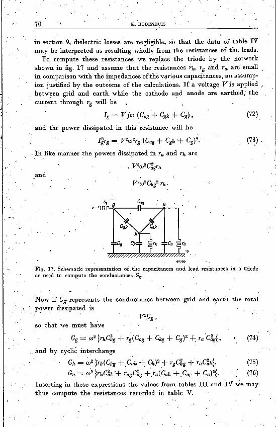
in section 9, dielectric losses are negligible, so that the data of table IVmay be interpreted as resulting wholly from the resistances of the leads.
To compute these resistances We replace the triode by the networkshown in fig. 17 and assume that the resistances Tic, Tg and Ta are smallin comparison with the impedances of the various capacitances, an assump-ion justified by the outcome of the calculations. If a voltage V is applied /
, between grid and earth while the cathode and anode are earthed; thecurrent through Tg will be
Ig = Vjw (Cag + Cglc+ Cg), (72)
and the power dissipated in this resistance will be
IiTg ==, V2W2Tg (Cag + Cglc -+ Cg)2.
-,In like manner the powers dissipated in Ta and Tic are
V2 2C2• W agTa
(73) .,
and
150390
Fig. 17. Schematic representation of ,the capacitances and lead resistances in a triodeas used to comp'ute the conductances Gg•
Now if Gif represents the conductance between grid and e,arth the totalpower dissipated is
so that we must have
Gg = w2 ~TlcC~g+ Tg(Cag + Clcg+ Cg)2 +: Ta'C~g~, (74)
_ and by cyclic interchange. . ) .
GIc= w2 ~TIc(Clcg+ ICak +:' CIc)2+ TgCkg + TaC~Ic~,
Ga = ~2 ~TkC~k"+ Tagqg +'ra(Cak + .Cag + Ca)2~.
(75)(76)
Inserting in these expressions the values from tables III and IV we maythus compute the resistances recorded in table V.

/
,UMITING FREQUENCY OF OSCILLATOR TRIODE, '
TABLE V,. I
0'62 0'34
at 300 Mc/sec\ .
, ,Since, the skin-effect resistances vary as the square root of the.frequency,
the conductances will ,vary as the 5/2 power of the frequency, so thatfrom their valu~s at 300 Mc/sec the values at other frequencies can be atonce computed. The resultant ' data have been collected in ,~able VI.
TABLE VI
f 300 60Ó 1000 1500 2000 Mc/sec~
G~g 10 57 205 565 1160 {JÁ/V
"G~k 0 1 4 10 20 fLA/V
G~k 10 57 200 560 1150 fLA/V I
. 13. Evaluation of the losses in 'the emissive coating of the EC81
For the EC 81 we have:thickness of oxide coatingsurface area of oxide coating'clearance between surface and gridAssuming in addition th~t the oxide8=4,and a specific resistance e = 3 .om,we find
50 (.I.,9'8 mmê ,125 (.I..
coating, has a dielectric constant
Cl ' 6'94 pF,, C2 = 0'694 pF ,Tl = 15'3.
I '. ,
Inserting these data in equation (65) we derive the values of Ge givenin tabl~ VII. The' average value of Ge calculated from observations át300 Mc/sec on 20 different valves was 24'2 (.I.AjV, in satisfactoryagreement with the calculations recorded above. '
,I
71

. ', \
".)'
1 ,
",.. , of
", I
" ,I '., '
.--.,,' ..
. ,, , ,. \.~ ,
72 . ';...K. ROnENHUIS .. \
/I,0, \
'TABLE VII
f
295
300 . 2000 Mcfseè600 1000 1500
G. (1.AfV25 36887 189
14: The 'Iirirltin~ frequency of the EC 81
Writing,I K = 4(Gag + Ggk) (Gag+ Gak) - ~(s - 2Gag)2 + Z2~,
L = Gag + Gak,M = Gag + Ggk,N = s + Gag + Ggk ,
(77)(78)(79)(80)
. .where a.», Gag, Gak, and Ggk are given by (66), (67) and (68) the oscillatingconditions (13a) to (l~d) imply that oscillation of a triode will only-hepossible when one of the four quantities, ,K, L, M or N is negative, Intable' VIII the various data entering these oscillating ~onditions have
, ". ,
been collected from tables I, IV, and VII, and from these the values ofK, L, 'M and N ha~é been computed. It appears that K is the only factorthat assumes a negative value, and if we plot K against the frequency asin fig. 18 we see' that K becomes positive at a frequency of 1850 Mc/sec.
TABLE VIII
,.' ,;
f 300 600 1000 1500 2ÖOO Mcfse,c,
s 5360 4950 4040 2400 478 Il-AfVz ~ 1100 -1860 - 3320 -4360 -4360 Il-AfV .',
Re(Yag) -7 -25 -64 -133 -207 Il-AjVG~g 10 57 205 565 1160 Il-AfV
,Re(Yak) 339 334 322 298 202 I Il-AfVGal, 0 1 4 10 20 Il-AfV
<
.: Re<'Ygk) 111 4·38 1160 2390 3740 Il-AfV .'.GSk' 10 57 200 560 1150 Il-AfV.. G. I 25 87 189 295 368 , Il-AfV
~Gag 3 32 140 432 ' 953 Il-AfVGak 339 335 326 ' 308 282 ~ Il-AfVGgI' 146 582 1549 3245 5258 Il-AfV
,IC " .....,29.7.106•-27'4.106 -22·0.10G -10·5.10G +4:4.106 (IJ.AfV)2'L 442 367 466 740 1235 Il-AfV,M 149 614 .1689 3677 5211 Il-AfVN 5845 5867 5915 5953 6018 Il-A/V, . .
-,, .

I '
I-' -;
",.
mUTING 'FREQ~~JI(CY Ó"F ~SCILI:À~OR ;RIODE,' 73, '" i" r__ ~ __ ~ ,~,,_, ~ __ ~~ __ ~ __ ~ ~'~ ~" I
"
, " '''''.j'
" ... .This should be the limiting frequency of the EC 81, whereas in out experi-ments the highest frequency at which the valve could be made to oscillatewas 1600 Mc/sec, the theoretical thus being higher than the practicalvalue. 'I'his mayhe explained as a resulting from the assumption that the.,external circuit is an ideal one, a condition that can never be fully reali~ed : .in practice. Another theoretical inaccuracy' may arise from the formulaêused to account for transit-time effects. .
"
-' 'f'~
',\,
60399
,Fig. 18. The quantity K as a function of the frequency. Curve B represents K when theseries resistances of the electrode leads are assumed to be zero. , /
All in aU it may be concluded that the theory as' developed above'constitutes a satisfactory approximation, the discrepancy 'with respect toactual observation being not more than 15%. ..I~ fig. 18 curve B represents the value' 6f J( obtained whe~ the lead'
resistances are taken as being equal to zero. 'In that case K remainsmarkedly negative up to a frequency of 2000 Mc/sèc' so that, under thesecircumstances, we should be able to ,reach, much higher -frequencies. This.clearly demonstrates the great importance of reducing the lead resistances~, •~a measure that 'has b~en accomplished in' thè so-called disc-seal valves,where the circumferential contact with the external circuit is established .' .by means of discs, forming an integral part of the electrodes. . ,"15. T~e èxperimental d,etermiDation of the limiting fre~enèy ,
As shown in section 4, in order to' adjust the feedback ratio a = x +ir. ;','",, ~ , ."-
to an,y value desired, we must he able to adjust the imaginary, part 'of
"

74 K. RODENHUIS .
three of the four coefficients of the feedback four-pole to any set of.pres-c~ibed values, while the imaginary part of the fourth coefficient dependson one of the other three. Thus optimum oscillation conditions requirein practice the use of a feedback four-pole the four coefficients of which
, 'can be adjusted at will. Since we are only concerned with th~ imaginaryparts of these coefficients the four-pole may be composed of variable self-inductances and condensers or, àt high frequencies, of Lecher systemsor coaxial lines of variable lengths.The simplest types of four-poles fulfilling these conditions are the IT
'and the T circuits, represented in fig. 19 togethe.r with the correspondingoscillator circuits .
. '
Fig. 19a. TI circuit of the feedback four-pole and the corresponding oscillator circuit.Fig. 19b. T circuit of the feedback four-pole and the corresponding 'oscillator. circuit.
, In the range of decimetrio wavelcngths the circuit of fig. 19a is unsuitable,since at least one of the three admittances must necessarily consist oftwo parallel conductors, In that case, however, in addition to the admit-tance' of the two wires with respect to each other, we have also to considerthe admittance of each with respect to earth. Moreover these conductorscannot be connected directly to the electrodes of'the valve, but this con- "neetion has to b~ made via externalleads sometimes including the. socket, 'which means the interposition of additional self-inductances; the actual-. circuit will be as shown-in fig. 20. Hence the circuit of fig. 19b should bepreferred. ,
In this circuit' the impedances Zl' Z2 and Z3 may be a set of short-circuited' coaxial leads -the impedances of' which can be made to vary

"
" ..\ 'LIMITING FREQUEN6¥ OF OSC~LLATOR TRIODE ::
, ,
from ~joo to '+joo, if we disregard the losses. Correction for the self·'inductances of the connections with the valve' can now be made simplyby changing the length of the coaxial lines (see fig. 21); th~ range ofadjustment is thereby not altered.
"
60401
Fig. 20. The circuit of fig. 19a tàking into' account the self-inductances of the connectingleads. I '
If, at veryhigh frequencies, it should hefound i.mpossible to adjust theadmittance as desired owing to the impossibility of approaching the short-, circuit close enough to the electrodes of the valve, this can be remedied "by moving the short-circuit one or more half wavelengths farther away.
60402
Fig. 21.,The oscillator circuit 'of fig. 19b taking into account the' self-inductances of theconnecting leads. .
\
Though this measure creates the possibility, of oscillations at a lower, frequency, namely at that frequency for which the effective length of thecoaxial 'Ieads equals a quarter of a wavelength, such oscillations, 'caneffectively, be prevented by placing the load determining the power

76---~ K. RODENHUIS
Fig. 22. The star oscillator. A coaxial wavelength meter used to determine the frequencyand connected to the oscillator by a cable is seen in the foreground. The tube on the leftis the coaxial lead connected to the cathode; the tubes on the right are those connectedto grid and anode.
Fig. 23. Circuit diagram of the apparatus for determining the power delivered by anoscillator triode as a function of the frequency. Cathode, grid and anode are capacitivelyconnected to coaxial impedances of variable lengths, conductors passing through theinner tubes of these impedances serving for the d.c. supply. The piston in the variableanode impedance is capacitive, so that the inner and outer leads are short-circnitedat high frequencies but insulated against d.c. This makes it possible to measure resistanceof the electric lamp serving as load, and to use this resis tance as a measure of thepower dissipated. The bulb itself has been mounted on a separate bridge' which canbe moved along the ánode lead in order to adjust the impedance of the load to theproperties of the oscillator. The d.c. supply lead and one of the heater current leads passthrough the inner conductor of the cathode impedance. One side of the apparatus hasbeen fitted with.a capacitive probe to be connected to a wavelength meter by meansof a cable.

, "•.1. \ ' J
~'.: 'l
_", ÜMi~lNG FREQCENCY OF OSCILLATOH TRIODE. "~., 77 . ,
delivered (for example, a 'small elect~ic bulb) as' close to the valve aspossible, and in the neighbourhood of a nodal point of th~ higher fre-;quencies .. This load will then cause only a small damping at' the high 'frequency but such a, heavy damping at' the lower frequency -that oscil-lations at.that lower frequency are precluded.
The ohservations on the EC ~l ,~ere ~ade with an apparatus constructed .on these principles and shown' hi' fig. 22; the circuit diagram was thatof fig. 23. r
The curves in fig. 15 represent the power deli vered as a function of the'. wavelength determlned in this manner.
. ,,
.' Eindhooen, July 19,49
r.
,- ,
".1
,.....'.
,,' ,,'I
REFERENCES, (
1)' E. M. Me, Millan, Violation of the reciprocity theorem in linear passive electro-mechanical systems, J. acoust. Soc. Am. 18, 344-347, 1946.' .'
2) C. J. Bakker and G. de Vries, On vacuum tube electrónics, Physica, 's-Grav., 2,683-689, 1935. . , .
3) H. Zuhrt, Die Verstärkung einer Drcielektrodenröhre mit ebenen Elekt~oden beiultrahohen Frequenzen, Hochfrcqucnztech. Elektroak. 47, 58·64, 79-88, 1936. .
\'
, .. \ .
...
.' .~",
'I. ••
, .
.' ,