vacuum circuit breakers - assets.new.siemens.com
TRANSCRIPT

Vacuum circuit breakers for generator switching applications
siemens.com/generatorswitchgear

Grow with your requirements No question: The worldwide energy demand will continue to increase rapidly, placing higher performance requirements on energy suppliers and industrial facilities.
To offer them a decisive advantage, for decades Siemens has been developing and improving high-current and genera-tor circuit-breakers, which can comply with ever-increasing requirements. In addition to ever higher rated currents required in central power plants, there is increasing demand from distributed power plants in the lower performance range, which with more frequent swit-ching operations defines a new dimen-sion of requirements. In this, reliability and low maintenance remain the top pri-ority over the entire life cycle. With com-prehensive simula tions, preliminary stu-dies, state-of-the-art development technologies, and modern manufacturing processes, Siemens sustainably maintains its leading position in the field of vacuum circuit-breakers.
With Siemens products, the performance, reliability and economic efficiency of the entire switchgear assembly grows, and life-cycle costs are reduced.
Over 45 years of experience in vacuum switching technologyIn particular, Siemens has perfected its vacuum circuit-breakers for generator switching applications, where they are
subjected to high thermal and mechanical stress: ■■ Special contact material for minimum contact wear
■■ Specifically developed contact system■■ Optimized design for efficient cooling■■ Post insulator construction for highest mechanical stability
■■ Safe breaking operations by controlling long arcing times even in case of missing zero crossings
■■ Transient recovery voltages with high rates-of-rise, typical for generator networks, are controlled without additional capacitors.
Application of the proven vacuum switching technology is thus possible for higher short-circuit currents, which formerly had to be implemented with SF6 switching technology.
Vacuum switching technology established on the marketThe exceptional economic and techno-logical aspects of the vacuum quenching principle have made the vacuum circuit-breaker the device that is mostly used worldwide for voltage ratings from 1 kV to 52 kV.
In the last years, the application of the vacuum switching technology has expanded and it is largely accepted even in the field of generator switching duties.
Siemens offers a wide range of vacuum circuit-breakers for generator switching protection.
The new generator vacuum circuit breaker in SION design is ideal for the integration of small generators in a compact switch panel group.
Convincing all along the lineSwitchgear and switching devices from Siemens
2
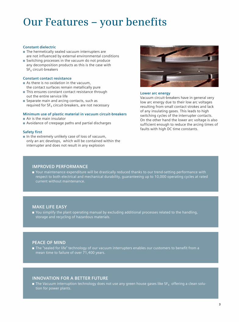
Lower arc energyVacuum circuit-breakers have in general very low arc energy due to their low arc voltages resulting from small contact strokes and lack of any insulating gases. This leads to high switching cycles of the interrupter contacts. On the other hand the lower arc voltage is also sufficient enough to reduce the arcing times of faults with high DC time constants.
Constant dielectric■■ The hermetically sealed vacuum interrupters are are not influenced by external environmental conditions
■■ Switching processes in the vacuum do not produce any decomposition products as this is the case with SF6 circuit-breakers
Constant contact resistance■■ As there is no oxidation in the vacuum, the contact surfaces remain metallically pure
■■ This ensures constant contact resistance through out the entire service life
■■ Separate main and arcing contacts, such as required for SF6 circuit-breakers, are not necessary
Minimum use of plastic material in vacuum circuit-breakers■■ Air is the main insulator■■ Avoidance of creepage paths and partial discharges
Safety first ■■ In the extremely unlikely case of loss of vacuum, only an arc develops, which will be contained within the interrupter and does not result in any explosion
IMPROVED PERFORMANCE ■■ Your maintenance expenditure will be drastically reduced thanks to our trend-setting performance with respect to both electrical and mechanical durability, guaranteeing up to 10,000 operating cycles at rated current without maintenance.
MAKE LIFE EASY ■■ You simplify the plant operating manual by excluding additional processes related to the handling, storage and recycling of hazardous materials.
PEACE OF MIND ■■ The "sealed for life" technology of our vacuum interrupters enables our customers to benefit from a mean time to failure of over 71,400 years.
INNOVATION FOR A BETTER FUTURE■■ The Vacuum interruption technology does not use any green house gases like SF6 offering a clean solu-tion for power plants.
Our Features – your benefits
3

Type-tested according to all relevant standards Type tests as specified in IEC 62271-100 are performed as a rule for all Siemens circuit-breakers. Generator circuit-breakers are additionally tested in accordance with IEEE C37.013 or IEC / IEEE 62271-37-013. This Standard is the only worldwide standard to take into account the increased requirements to which the devices are subjected when switching generators. As a result the standard has been enhanced to a Dual Logo IEEE/IEC leading standard.
Standard IEEE C37.013 or IEC / IEEE 62271-37-013 includes in particular: ■■ For generator-side faults: High DC components and the resulting missing zero crossings
■■ For system-side faults: Higher TRV rates-of-rise■■ Higher test voltage levels
Proven quality from Siemens
Vacuum circuit-breakers for generator switching applications up to 17.5 kV
Classic design Phase-segregated design
with forced cooling
10,5 kV 15,75 kV
220 MVA 340 MVA
180 MVA 270 MVA
140 MVA 210 MVA
110 MVA 170 MVA
70 MVA 100 MVA
50 MVA 80 MVA
Ir
12.500 A
14.000 A
8.000 A
6.300 A
4.000 A
63 – 110 kA Isc
3AH361*
3.150 A
10.000 A
40 kA31,5 kA 50 kA 63 kA 72 kA 80 kA
3AE2
3AK7
3AH373
3AH381
3AH371
250 MVA 380 MVA
*Complete module for each phase with integrated main disconnector, earthing switches and starting switch
4

Today, in numerous power supply companies worldwide, the high-current and generator circuit-breaker 3AH38 is standard for breaking normal currents up to 4,000 A. It was the first vacuum circuit-breaker with 63 kA and 72 kA to be type-tested according to the criteria of generator circuit-breaker standard IEEE C37.013.
Its counterpart for higher generator ratings is 3AH37, the first vacuum circuit-breaker worldwide which can carry a normal current of 6,300 A on a sustained basis up to 24 kV without forced cooling. Moreover, at a voltage level of 24 kV it controls short-circuit currents up to 72 kA – with forced cooling, the 3AH37 can be operated with normal currents up to 8,000 A.
The 3AH36 generator switching module was developed especially for phase-segregated enclosed generator switchgear and applicable up to 450 MVA power range.
3AH36, 3AH37 and 3AH38
Vacuum circuit-breakers for generator switching applications up to 24 kV
Classic design Phase-segregated design
with forced cooling
*Complete module for each phase with integrated main disconnector, earthing switches and starting switch
21 kV
450 MVA
360 MVA
290 MVA
220 MVA
140 MVA
Ir
12.500 A
14.000 A
8.000 A
6.300 A
4.000 A
50 kA 63 kA 72 kA 80 kA 63 – 100 kA Isc
3AH362*
3AH374
3AH372
10.000 A
500 MVA
5

The recipe for success of the 3AK7 has now also been applied to the SION: Along with the SION 3AE5 31.5 kA and new 40 kA IEC standard circuit-breaker, there is a virtually identical version as a type-tested IEC/ IEEE 62271-37-013 generator circuit-breaker for 31.5 kA. This offers panelbuilders the lucrative opportunity to cover even smaller generator switching applications along-side the IEC high-voltage market.The SION 3AE2 is available not only with contact arms and contact systems but also as a withdrawable version.
Compact design – high perfomanceThe pole shell design enables the slen-der width and at the same time provides for high currents of up to 3,150 A, and 4,000 A with forced cooling.Depending on the version, the vacuum circuit-breakers are dimensioned to 10,000/ 30,000 operating cycles.
3AE2 / 3AK7The compact vacuum circuit-breakers for generator switching applications
Rated short-circuit breaking current ISC (3 s) [kA] 31,5 40 50
DC component of rated short-circuit breaking current [%] 65 70 75
Asymmetrical breaking current [kA] 43 56 73
Rated short-circuit making current [kA] 87 110 137
Generator short-circuit breaking current ISCG [kA] 25 1) 18,5 2) 20 25 1) 25 2)
DC component of short-circuit breaking current [%] 110 130 120 110 130
Asymmetrical breaking current [kA] 46 39 39 46 52
Rated currents [A] 1.250; 2.000; 2.500; 3.150; 4.000 (with forced cooling)
Rated voltage 12 kV50/60 Hz; Up = 75 kV; Ud = 28 kV (optional 42 kV)
3AE2185 3AK753 3AK755
Rated voltage 15 kV / 17,5 kV*50/60 Hz; Up = 95 kV; Ud = 38 kV (optional 42 kV)
3AE2285 3AK763 3AK765
Rated operating sequence
– For short-circuit breaking current CO – 30 min – CO, up to 30 short-circuit breaking operationsFurther operating sequences possible: O – 3 min – CO – 3 min – CO, …
– For operating current CO – 3 min – CO, up to 10,000 / 30,000 operating cycles
* Ud and Up fulfill the specifications for rated voltage 15 kV in accordance with IEC /IEEE 62271-37-013 and for 17.5 kV in accordance with IEC 62271-1001/ 2) Class G1/ Class G2 – Classification IEC/IEEE 62271-37-013
The 3AE2 and the 3AK7, for exam-ple, are used in the Siemens NXAIR switchboard for switching generators.
6
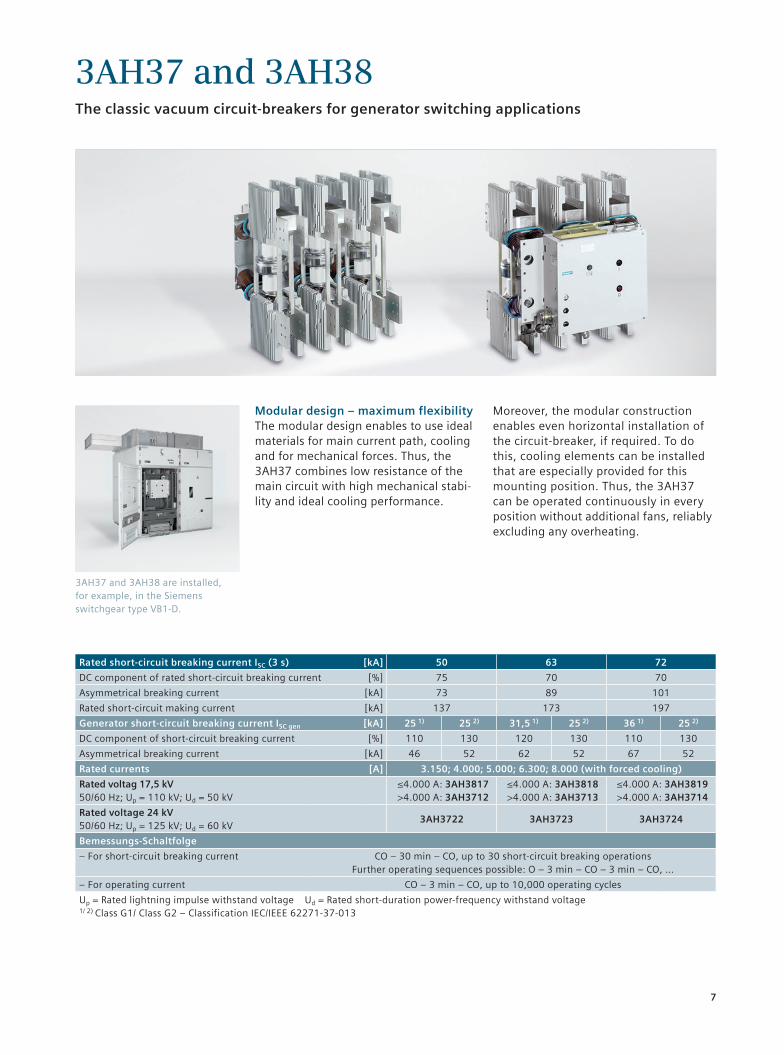
Modular design – maximum flexibilityThe modular design enables to use ideal materials for main current path, cooling and for mechanical forces. Thus, the 3AH37 combines low resistance of the main circuit with high mechanical stabi-lity and ideal cooling performance.
Moreover, the modular construction enables even horizontal installation of the circuit-breaker, if required. To do this, cooling elements can be installed that are especially provided for this mounting position. Thus, the 3AH37 can be operated continuously in every position without additional fans, reliably excluding any overheating.
3AH37 and 3AH38 are installed, for example, in the Siemens switchgear type VB1-D.
3AH37 and 3AH38The classic vacuum circuit-breakers for generator switching applications
Rated short-circuit breaking current ISC (3 s) [kA] 50 63 72
DC component of rated short-circuit breaking current [%] 75 70 70
Asymmetrical breaking current [kA] 73 89 101
Rated short-circuit making current [kA] 137 173 197
Generator short-circuit breaking current ISC gen [kA] 25 1) 25 2) 31,5 1) 25 2) 36 1) 25 2)
DC component of short-circuit breaking current [%] 110 130 120 130 110 130
Asymmetrical breaking current [kA] 46 52 62 52 67 52
Rated currents [A] 3.150; 4.000; 5.000; 6.300; 8.000 (with forced cooling)
Rated voltag 17,5 kV50/60 Hz; Up = 110 kV; Ud = 50 kV
≤4.000 A: 3AH3817 >4.000 A: 3AH3712
≤4.000 A: 3AH3818 >4.000 A: 3AH3713
≤4.000 A: 3AH3819 >4.000 A: 3AH3714
Rated voltage 24 kV50/60 Hz; Up = 125 kV; Ud = 60 kV
3AH3722 3AH3723 3AH3724
Bemessungs-Schaltfolge
– For short-circuit breaking current CO – 30 min – CO, up to 30 short-circuit breaking operationsFurther operating sequences possible: O – 3 min – CO – 3 min – CO, …
– For operating current CO – 3 min – CO, up to 10,000 operating cycles
Up = Rated lightning impulse withstand voltage Ud = Rated short-duration power-frequency withstand voltage1/ 2) Class G1/ Class G2 – Classification IEC/IEEE 62271-37-013
7

In the case of generator switching appli-cations with phase-segregated designs, the requirements for pole synchronism have been implemented in accordance with IEC 62271-100, and tested with short-circuit currents up to 80 kA and operating currents up to 12,000 A.
Example of a retrofit installation of the 3AH37 90 kA circuit-breaker
3AH37 up to 80 kA – phase-segregatedThe three circuit-breaker solution for phase-segregated design
Rated short-circuit breaking current ISC (3 s) [kA] 50 63 72 80
DC component of rated short-circuit breaking current [%] 75 70 70 70
Asymmetrical breaking current [kA] 73 89 101 113
Rated short-circuit making current [kA] 137 173 197 219
Generator short-circuit breaking current ISC gen [kA] 25 1) 25 2) 31.5 1) 25 2) 36 1) 25 2) 40 1) 40 2)
DC component of short-circuit breaking current [%] 110 130 120 130 110 130 110 130
Asymmetrical breaking current [kA] 46 52 62 52 67 52 74 84
Rated currents [A] 4,000; 5,000; 6,300; 8,000; 10,000; 12,000
Rated voltage 17.5 kV 50/60 Hz; Up = 110 kV; Ud = 50 kV
3AH3732 3AH3733 3AH3734 3AH3735
Rated voltage 24 kV50/60 Hz; Up = 125 kV; Ud = 60 kV
3AH3742 3AH3743 3AH3744 3AH3745
Rated operating sequence
– For short-circuit breaking current CO – 30 min – CO, up to 30 short-circuit breaking operationsFurther operating sequences possible: O – 3 min – CO – 3 min – CO, …
– For operating current CO – 3 min – CO, up to 10,000 operating cycles
Up = Rated lightning impulse withstand voltage Ud = Rated short-duration power-frequency withstand voltage *Higher ratings on request1/ 2) Class G1/ Class G2 – Classification IEC/IEEE 62271-37-013
8

3AH36 110 kA – phase-segregatedThe circuit-breaker module solution for phase-segregated design
Installation of the 3AH36 generator circuit-breaker module solution on a common frame as a HB3-C retrofit solution
Rated short-circuit breaking current ISC (3 s) [kA] 63 80 100 110
DC component of rated short-circuit breaking current [%] 70 70 75 60
Asymmetrical breaking current [kA] 89 113 146 144
Rated short-circuit making current [kA] 173 219 274 302
Generator short-circuit breaking current ISC gen [kA] 31,52) 402) 632) 752)
DC component of short-circuit breaking current [%] 130 130 130 130
Asymmetrical breaking current [kA] 66 84 132 157
Rated currents [A] 8,000; 10,000; 12,500; 14,000
Rated voltage 17.5 kV50/60 Hz; Up = 110 kV; Ud = 50 kV
3AH3613 3AH3615 3AH3617 3AH3618
Rated voltage 24 kV50/60 Hz; Up = 125 kV; Ud = 60 kV
3AH3623 3AH3625 3AH3627 –
Rated operating sequence
– For short-circuit breaking current CO – 30 min – CO, up to 30 short-circuit breaking operationsFurther operating sequences possible: O – 3 min – CO – 3 min – CO, …
– For operating current CO – 3 min – CO, up to 10,000 operating cycles
Up = Rated lightning impulse withstand voltage Ud = Rated short-duration power-frequency withstand voltage
The 110 kA generator circuit-breaker module was developed especially for straight-line current carrying, such as is required in compact generator switch-gear. The following options have been integrated:■■ Main disconnector ■■ Transformer-side earthing switch■■ Generator-side earthing switch■■ Starting switch
3AH36 generator circuit-breaker module solution is also used sin-gle-pole enclosed in the Siemens HB3 switchboard.
2) Class G2 – Classification IEC/EEE 62271-37-013
3AH36 generator circuit-breaker module
9

More than a good technologyThe Siemens performance portfolio – from consultancy to a reliable switchgear
Correct selection of the generator circuit-breakerSelection criteria are:■■ Rated voltage■■ Rated current■■ Response to System-side short circuit■■ Response to Generator-side short circuit
Design for normal operationIn the vicinity of generators, special conditions arise. Thus, every application is specifically adapted to the customer’s requirements.
Basis for the solutions is the application guide in IEC / IEEE 62271-37-013.
Design for the case of faultIn general, the symmetrical system-side short-circuit current (case of fault a) is higher than the generator-side short-circuit current (case of fault b), and therefore determines the required breaking capacity of the generator circuit-breaker.
Fault location a: System source shortcircuit with continuous AC component
Fault location b: Generator-Generator source short-circuit with zero missing
* The fault currents are superimposed in fault location c).
In the case of fault, two different fault current components overlap. The short-circuit current component to be interrupted is supplied bya) High-voltage system orb) Generator orc) High-voltage system and generatorr
Auxiliary transformer
System transformer
c)*b)
a)
G
The DC component of the generator- side short-circuit current is higher, which must also be taken into account for assessment of the breaking capacity.
Overvoltage protection measuresFrom the view of the vacuum switching principle, no overvoltage protection measures are necessary for switching generators, unless the short-circuit current of the generator is smaller than 600 A. However, surge arresters are usually equipped for this switching application in order to protect the expensive equipment from all other overvoltages.
Sectional view of a vacuum interrupter
10
For this purpose, we kindly ask you to submit the following data:■■ Data sheets of: – Generator – Transformer – Auxiliary transformer & motors, if applicable
■■ Single-line diagram■■ Information on equipment operation, e.g. interconnected circuits
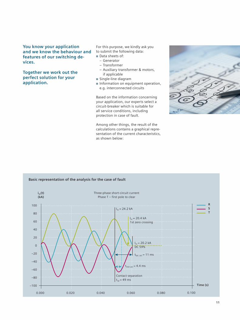
Based on the information concerning your application, our experts select a circuit-breaker which is suitable for all service conditions, including protection in case of fault.
Among other things, the result of the calculations contains a graphical repre-sentation of the current characteristics, as shown below:
You know your application and we know the behaviour and features of our switching de-vices.
Together we work out the perfect solution for your application.
100
80
60
40
20
0
–20
–40
–60
–80
–100
isc(t) (kA)
0.000 0.020 0.040 0.060
Time (s)
0.080 0.100
Three-phase short-circuit current Phase T – first pole to clear
Isc = 20.2 kA DC 59%
ttot. arc = 11 ms
Contact separation tcp = 49 ms
Isc = 24.2 kA
Isc = 20.4 kA 1st zero crossing
R S T
Basic representation of the analysis for the case of fault
tmin arc = 4.4 ms
11

Siemens AG Smart Infrastructure Low Voltage Products Siemensstraße 10 93055 Regensburg Germany
For more information, please contact our Customer Support Center.
Tel.: +49 (0) 180 524 8437 Fax: +49 (0) 180 524 2471 (charges vary depending on provider) Email: [email protected]
© Siemens 2020
Printed in Germany TH 260-120542 WS 04130.5
Article No. EMLP-B10161-00-7600
All rights reserved. Trademarks mentioned in this document are the property of Siemens AG, its affiliates, or their respective owners.
Subject to change without prior notice. The information in this document contains general descrip-tions of the technical options availa-ble, which do not always have to be present in individual cases. The required features should therefore be specified in each individual case at the time of closing the contract.
Securing more than
80 GWof electricity
production
1stcompany to introduce
110 kA generator
vacuum circuit-breaker
More than
3,650GVCB´s installed
in 57 countries
More than
25years of
GVCB experience