vd0c32s301b instruction bulletin raleigh, nc, usa replacement . . . . . . . . . . . . . . . . . . ....
TRANSCRIPT

Instruction BulletinVD0C32S301B
June 1998Raleigh, NC, USA
ALTISTART
® 46Soft Start ControllerUser’s Manual
efesotomasyon.com

© 1998 Square D Company. All rights reserved. This document may not be copied in whole or inpart, or transferred to any other media, without the written permission of Square D.
ALTISTART and TCS are registered trademarks of Telemecanique S.A. or its successor-in-interest,Schneider Electric S.A.
InTele Braking is a trademark of Square D Company.
HAZARDOUS VOLTAGE• Read and understand this manual in its entirety before installing or operating
ALTISTART 46 (ATS46) controllers. Installation, adjustment, repair, and maintenance of these controllers must be performed by qualified personnel.
• Disconnect all power before servicing controller. • DO NOT touch unshielded components or terminal strip screw connections
with voltage present.• Install all covers before applying power or starting and stopping the
controller.• User is responsible for conforming to all applicable code requirements with
respect to grounding all equipment. See Figures 1-5 on pages 5-7 for grounding points.
• Many parts in this controller, including printed wiring boards, operate at line voltage. DO NOT TOUCH. Use only electrically-insulated tools while making adjustments.
Before installing controller:• Disconnect all power.• Place a “DO NOT TURN ON” label on the controller disconnect.• Lock disconnect in open position.
Electrical shock will result in death or serious injury.
DANGER
efesotomasyon.com

Bulletin No. VD0C32S301B ALTISTART® 46 Soft Start ControllerJune 1998 Contents
i© 1998 Square D All Rights Reserved
INTRODUCTION . . . . . . . . . . . . . . . . . . . . . . . . . . . . . . . . . . . . . . . . . . . . . . . . . . . . .2Definition of Terms . . . . . . . . . . . . . . . . . . . . . . . . . . . . . . . . . . . . . . . . . . . . . . . . .2
TECHNICAL CHARACTERISTICS. . . . . . . . . . . . . . . . . . . . . . . . . . . . . . . . . . . . . . . .2DIMENSIONS AND WEIGHTS . . . . . . . . . . . . . . . . . . . . . . . . . . . . . . . . . . . . . . . . . . .4HANDLING THE CONTROLLER . . . . . . . . . . . . . . . . . . . . . . . . . . . . . . . . . . . . . . . . .8SERIAL AND MODEL NUMBERS . . . . . . . . . . . . . . . . . . . . . . . . . . . . . . . . . . . . . . . .8INSTALLATION PRECAUTIONS . . . . . . . . . . . . . . . . . . . . . . . . . . . . . . . . . . . . . . . . .9MOUNTING PRECAUTIONS . . . . . . . . . . . . . . . . . . . . . . . . . . . . . . . . . . . . . . . . . . .12
Mounting in General Purpose Metal Enclosure . . . . . . . . . . . . . . . . . . . . . . . . . . .12Mounting in Dust and Damp-proof Metal Enclosure . . . . . . . . . . . . . . . . . . . . . . .13Thermal Considerations for Sizing Enclosures . . . . . . . . . . . . . . . . . . . . . . . . . . .13
WIRING. . . . . . . . . . . . . . . . . . . . . . . . . . . . . . . . . . . . . . . . . . . . . . . . . . . . . . . . . . .16General Wiring Practices. . . . . . . . . . . . . . . . . . . . . . . . . . . . . . . . . . . . . . . . . . .16Adaptation to Line Input . . . . . . . . . . . . . . . . . . . . . . . . . . . . . . . . . . . . . . . . . . .16Power Connections . . . . . . . . . . . . . . . . . . . . . . . . . . . . . . . . . . . . . . . . . . . . . .16Bus Connection . . . . . . . . . . . . . . . . . . . . . . . . . . . . . . . . . . . . . . . . . . . . . . . . . .18
CONTROL CONNECTIONS . . . . . . . . . . . . . . . . . . . . . . . . . . . . . . . . . . . . . . . . . . .19Logic Input . . . . . . . . . . . . . . . . . . . . . . . . . . . . . . . . . . . . . . . . . . . . . . . . . . . . . .21Logic Outputs . . . . . . . . . . . . . . . . . . . . . . . . . . . . . . . . . . . . . . . . . . . . . . . . . . .21Analog Output . . . . . . . . . . . . . . . . . . . . . . . . . . . . . . . . . . . . . . . . . . . . . . . . . . .21
REMOTE MOUNTING KEYPAD. . . . . . . . . . . . . . . . . . . . . . . . . . . . . . . . . . . . . . . .22CONTROL CIRCUIT DIAGRAMS. . . . . . . . . . . . . . . . . . . . . . . . . . . . . . . . . . . . . . .22RECOMMENDED COMPONENT LIST . . . . . . . . . . . . . . . . . . . . . . . . . . . . . . . . . .26
SOFT START APPLICATION . . . . . . . . . . . . . . . . . . . . . . . . . . . . . . . . . . . . . . . . . . .30Standard Duty Applications . . . . . . . . . . . . . . . . . . . . . . . . . . . . . . . . . . . . . . . . . .30Heavy Duty Applications . . . . . . . . . . . . . . . . . . . . . . . . . . . . . . . . . . . . . . . . . . . .30Reduced Torque . . . . . . . . . . . . . . . . . . . . . . . . . . . . . . . . . . . . . . . . . . . . . . . . . .30
MODES OF STARTING . . . . . . . . . . . . . . . . . . . . . . . . . . . . . . . . . . . . . . . . . . . . . . .31Acceleration Ramp . . . . . . . . . . . . . . . . . . . . . . . . . . . . . . . . . . . . . . . . . . . . . . . .31Torque Limit. . . . . . . . . . . . . . . . . . . . . . . . . . . . . . . . . . . . . . . . . . . . . . . . . . . . . .32Current Limit . . . . . . . . . . . . . . . . . . . . . . . . . . . . . . . . . . . . . . . . . . . . . . . . . . . . .32Voltage Boost . . . . . . . . . . . . . . . . . . . . . . . . . . . . . . . . . . . . . . . . . . . . . . . . . . . .32
MODES OF STOPPING . . . . . . . . . . . . . . . . . . . . . . . . . . . . . . . . . . . . . . . . . . . . . . .32Deceleration Ramp . . . . . . . . . . . . . . . . . . . . . . . . . . . . . . . . . . . . . . . . . . . . . . . .32InTele Braking . . . . . . . . . . . . . . . . . . . . . . . . . . . . . . . . . . . . . . . . . . . . . . . . . . . .33
MOTOR PROTECTION AND DIAGNOSTICS . . . . . . . . . . . . . . . . . . . . . . . . . . . . . .33Thermal Overload Protection. . . . . . . . . . . . . . . . . . . . . . . . . . . . . . . . . . . . . . . . .33Excessive Cycling Prevention . . . . . . . . . . . . . . . . . . . . . . . . . . . . . . . . . . . . . . . .36Stall and Steady State Protection . . . . . . . . . . . . . . . . . . . . . . . . . . . . . . . . . . . . .37Protection from Line Faults . . . . . . . . . . . . . . . . . . . . . . . . . . . . . . . . . . . . . . . . . .38
CONTROLLER I/O CONFIGURATION. . . . . . . . . . . . . . . . . . . . . . . . . . . . . . . . . . . .38Faults/ISO Contactor Control Relays . . . . . . . . . . . . . . . . . . . . . . . . . . . . . . . . . .38End of Start-Up Relay . . . . . . . . . . . . . . . . . . . . . . . . . . . . . . . . . . . . . . . . . . . . . .38Logic Output . . . . . . . . . . . . . . . . . . . . . . . . . . . . . . . . . . . . . . . . . . . . . . . . . . . . .38Analog Output . . . . . . . . . . . . . . . . . . . . . . . . . . . . . . . . . . . . . . . . . . . . . . . . . . . .39Logic Input . . . . . . . . . . . . . . . . . . . . . . . . . . . . . . . . . . . . . . . . . . . . . . . . . . . . . . .39
DISPLAY OF MOTOR VALUES . . . . . . . . . . . . . . . . . . . . . . . . . . . . . . . . . . . . . . . . .39
CHAPTER 1—RECEIVING AND INSTALLATION
CHAPTER 2—WIRING
CHAPTER 3—APPLICATION AND PROTECTION
efesotomasyon.com

ALTISTART® 46 Soft Start Controller Bulletin No. VD0C32S301BContents June 1998
© 1998 Square D All Rights Reservedii
FACTORY PRESETS. . . . . . . . . . . . . . . . . . . . . . . . . . . . . . . . . . . . . . . . . . . . . . . . . 40USING THE KEYPAD. . . . . . . . . . . . . . . . . . . . . . . . . . . . . . . . . . . . . . . . . . . . . . . . . 40
Selecting a Menu Level. . . . . . . . . . . . . . . . . . . . . . . . . . . . . . . . . . . . . . . . . . . . . 41Operating the Pushbuttons . . . . . . . . . . . . . . . . . . . . . . . . . . . . . . . . . . . . . . . . . . 42
ADJUSTING CONTROLLER SETTINGS. . . . . . . . . . . . . . . . . . . . . . . . . . . . . . . . . . 43Control Parameters . . . . . . . . . . . . . . . . . . . . . . . . . . . . . . . . . . . . . . . . . . . . . . . . 43Parameter Flowcharts . . . . . . . . . . . . . . . . . . . . . . . . . . . . . . . . . . . . . . . . . . . . . . 45Setting the Motor Current . . . . . . . . . . . . . . . . . . . . . . . . . . . . . . . . . . . . . . . . . . . 51Setting the Current Limit . . . . . . . . . . . . . . . . . . . . . . . . . . . . . . . . . . . . . . . . . . . . 51Advanced Acceleration Ramp Adjustments . . . . . . . . . . . . . . . . . . . . . . . . . . . . . 51
INTRODUCTION . . . . . . . . . . . . . . . . . . . . . . . . . . . . . . . . . . . . . . . . . . . . . . . . . . . . 54Fault Relay Setup . . . . . . . . . . . . . . . . . . . . . . . . . . . . . . . . . . . . . . . . . . . . . . . . . 54Fault Display . . . . . . . . . . . . . . . . . . . . . . . . . . . . . . . . . . . . . . . . . . . . . . . . . . . . . 54
RESETTING THE CONTROLLER . . . . . . . . . . . . . . . . . . . . . . . . . . . . . . . . . . . . . . . 54Fault Definitions . . . . . . . . . . . . . . . . . . . . . . . . . . . . . . . . . . . . . . . . . . . . . . . . . . 55
TROUBLESHOOTING FAULTS. . . . . . . . . . . . . . . . . . . . . . . . . . . . . . . . . . . . . . . . . 56Phase Fault. . . . . . . . . . . . . . . . . . . . . . . . . . . . . . . . . . . . . . . . . . . . . . . . . . . . . . 56Frequency Fault . . . . . . . . . . . . . . . . . . . . . . . . . . . . . . . . . . . . . . . . . . . . . . . . . . 56Supply Fault with Run Command Present . . . . . . . . . . . . . . . . . . . . . . . . . . . . . . 57Motor Thermal Fault . . . . . . . . . . . . . . . . . . . . . . . . . . . . . . . . . . . . . . . . . . . . . . . 57Starter Thermal Fault . . . . . . . . . . . . . . . . . . . . . . . . . . . . . . . . . . . . . . . . . . . . . . 57Locked Rotor Fault . . . . . . . . . . . . . . . . . . . . . . . . . . . . . . . . . . . . . . . . . . . . . . . . 57Motor Underload Fault . . . . . . . . . . . . . . . . . . . . . . . . . . . . . . . . . . . . . . . . . . . . . 58Max Starting Time Exceeded . . . . . . . . . . . . . . . . . . . . . . . . . . . . . . . . . . . . . . . . 58External Fault . . . . . . . . . . . . . . . . . . . . . . . . . . . . . . . . . . . . . . . . . . . . . . . . . . . . 58Internal Serial Link Fault . . . . . . . . . . . . . . . . . . . . . . . . . . . . . . . . . . . . . . . . . . . . 58Overcurrent Fault . . . . . . . . . . . . . . . . . . . . . . . . . . . . . . . . . . . . . . . . . . . . . . . . . 59Internal Failure Fault . . . . . . . . . . . . . . . . . . . . . . . . . . . . . . . . . . . . . . . . . . . . . . . 59Phase Inversion Fault . . . . . . . . . . . . . . . . . . . . . . . . . . . . . . . . . . . . . . . . . . . . . . 59
INTRODUCTION . . . . . . . . . . . . . . . . . . . . . . . . . . . . . . . . . . . . . . . . . . . . . . . . . . . . 62PERSONNEL PROTECTION PRECAUTIONS . . . . . . . . . . . . . . . . . . . . . . . . . . . . . 62LIST OF TOOLS AND INSTRUMENTS . . . . . . . . . . . . . . . . . . . . . . . . . . . . . . . . . . . 63STANDARDS . . . . . . . . . . . . . . . . . . . . . . . . . . . . . . . . . . . . . . . . . . . . . . . . . . . . . . . 63PARTS REPLACEMENT . . . . . . . . . . . . . . . . . . . . . . . . . . . . . . . . . . . . . . . . . . . . . . 64CONTROL MODULE REPLACEMENT . . . . . . . . . . . . . . . . . . . . . . . . . . . . . . . . . . . 65POWER SECTION REPAIR. . . . . . . . . . . . . . . . . . . . . . . . . . . . . . . . . . . . . . . . . . . . 66
ATS46D17 to C32 Controllers . . . . . . . . . . . . . . . . . . . . . . . . . . . . . . . . . . . . . . . 66SCR Replacement . . . . . . . . . . . . . . . . . . . . . . . . . . . . . . . . . . . . . . . . . . . . . . . . 67FIlter Card Replacement . . . . . . . . . . . . . . . . . . . . . . . . . . . . . . . . . . . . . . . . . . . 69Thermal Switch and Fan Replacement . . . . . . . . . . . . . . . . . . . . . . . . . . . . . . . . 69Control Power Transformer (CPT) Replacement . . . . . . . . . . . . . . . . . . . . . . . . . 70
POWER SECTION REPAIR. . . . . . . . . . . . . . . . . . . . . . . . . . . . . . . . . . . . . . . . . . . . 71ATS46C41N to M12 Controllers . . . . . . . . . . . . . . . . . . . . . . . . . . . . . . . . . . . . . 71SCR Power Pole Assembly . . . . . . . . . . . . . . . . . . . . . . . . . . . . . . . . . . . . . . . . . 71Firing Interface Board Replacement . . . . . . . . . . . . . . . . . . . . . . . . . . . . . . . . . . . 72Current Measurement Board Replacement . . . . . . . . . . . . . . . . . . . . . . . . . . . . . 74Thermal Switch Replacement . . . . . . . . . . . . . . . . . . . . . . . . . . . . . . . . . . . . . . . . 75Fan Replacement . . . . . . . . . . . . . . . . . . . . . . . . . . . . . . . . . . . . . . . . . . . . . . . . . 75Control Power Transformer Replacement. . . . . . . . . . . . . . . . . . . . . . . . . . . . . . . 75
CHAPTER 4—CONTROLLER SETUP AND OPERATION
CHAPTER 5—FAULT MANAGEMENT
CHAPTER 6—SERVICING THE CONTROLLER
efesotomasyon.com

Bulletin No. VD0C32S301B ALTISTART® 46 Soft Start ControllerJune 1998 Contents
iii© 1998 Square D All Rights Reserved
efesotomasyon.com

ALTISTART® 46 Soft Start Controller Bulletin No. VD0C32S301BContents June 1998
© 1998 Square D All Rights Reservediv
efesotomasyon.com

VD0C32S301B Chapter 1—Receiving and InstallationJune 1998
1© 1998 Square D All Rights Reserved
INTRODUCTION . . . . . . . . . . . . . . . . . . . . . . . . . . . . . . . . . . . . . . . . . . . . . . . . . . . . . 2Definition of Terms . . . . . . . . . . . . . . . . . . . . . . . . . . . . . . . . . . . . . . . . . . . . . . . . . 2
TECHNICAL CHARACTERISTICS. . . . . . . . . . . . . . . . . . . . . . . . . . . . . . . . . . . . . . . . 2DIMENSIONS AND WEIGHTS. . . . . . . . . . . . . . . . . . . . . . . . . . . . . . . . . . . . . . . . . . . 4HANDLING THE CONTROLLER . . . . . . . . . . . . . . . . . . . . . . . . . . . . . . . . . . . . . . . . . 8SERIAL AND MODEL NUMBERS . . . . . . . . . . . . . . . . . . . . . . . . . . . . . . . . . . . . . . . . 8INSTALLATION PRECAUTIONS . . . . . . . . . . . . . . . . . . . . . . . . . . . . . . . . . . . . . . . . . 9MOUNTING PRECAUTIONS . . . . . . . . . . . . . . . . . . . . . . . . . . . . . . . . . . . . . . . . . . . 12
Mounting in General Purpose Metal Enclosure. . . . . . . . . . . . . . . . . . . . . . . . . . . 12Mounting in Dust and Damp-proof Metal Enclosure . . . . . . . . . . . . . . . . . . . . . . . 13Thermal Considerations for Sizing Enclosures . . . . . . . . . . . . . . . . . . . . . . . . . . . 13
CHAPTER 1—RECEIVING AND INSTALLATION
efesotomasyon.com

Chapter 1—Receiving and Installation VD0C32S301BSoft Start Application June 1998
© 1998 Square D All Rights Reserved2
The ALTISTART 46 (ATS46) Soft Start offers state-of-the-art acceleration and deceleration control of standard three-phase asynchronous induction (squirrel cage) motors. The ATS46 controller uses a new patented technology to control the motor performance based on the motor torque rather than simple voltage- or current-based control. Advanced control algorithms are incorporated to ensure smooth rotation throughout the starting ramp without mechanical instability at the end of starting.
A microprocessor continuously monitors the motor and controller performance to provide maximum protection of the controller, motor, and driven machinery. A variety of starting and stopping modes are standard. A digital keypad provides accurate controller setup and continuous motor performance display.
The ATS46 motor controller is available in 21 current ratings from 17 to 1200 amps. All models use a common control module for consistent and simple set up. ATS46 controllers are rated for use with 208/230, 380/400, or 460/500 V motors, and are self-adjusting for a 50 or 60 Hz supply frequency.
Some of the terms and acronyms used in this manual are defined in Table 1.
The following tables describe the technical characteristics of the ALTISTART 46.
Table 1: Definition of Terms
Term Definition
FLA Full load amps: the current rating of an induction motor at rated speed and load. This value may be found on the motor nameplate.
ICL Nominal current rating of the ATS46 controller. This value may be found on the controller nameplate.
In User defined motor current rating. Same as FLA.
Tn Nominal motor torque as calculated by ATS46 controller.
VnNominal voltage of supply power (mains supply). This should correspond to the motor rated voltage found on the motor nameplate.
Table 2: Environmental Characteristics
Degree of protection IP 20:ATS-46D17N to 46C14N startersIP 00:ATS-46C17N to 46M12N starters
Shock resistance Conforms to IEC 68-2-27: 15g, 11 ms:ATS-46D17N to 46D38N starters
Vibration resistance Conforms to IEC 68-2-6, NFC 20706 and BV1
Resistance to electrostatic discharges Conforms to IEC 1000-4-2 - level 3
Immunity to radio-electric interference Conforms to IEC 1000-4-3 - level 3
Immunity to rapid electrical transients Conforms to IEC 1000-4-4 - level 4
Ambient air temperatureOperation: 0 to + 40
°C without de-rating (between + 40
°C and + 60
°C, de-rate the ATS46 current by 1.2% for each
°C)Storage: -25
° to +70
°C
Maximum relative humidity 93% without condensation or dripping water
Maximum ambient pollution Degree 3 conforming to IEC 664
Maximum operating altitude 1000 m without de-rating (above this, de-rate the ATS46 current by 0.5% for each additional 100 m)
Operating position Maximum vertical inclination
± 15
° with respect to the normal mounting position
Degree of protection IP 20:ATS-46D17N to 46C14N startersIP 00:ATS-46C17N to 46M12N starters
INTRODUCTION
Definition of Terms
TECHNICALCHARACTERISTICS
efesotomasyon.com

VD0C32S301B Chapter 1—Receiving and InstallationJune 1998 Soft Start Application
3© 1998 Square D All Rights Reserved
Table 3: Electrical Characteristics
Three-phase supply voltage208 V -10% to 240 V +10%380 V -15% to 415 V +10%440 V -10% to 500 V +10%
Frequency 50 Hz
± 2.5 Hz or 60 Hz
± 3.6 Hz, self-adjusting
Rated current (ICL) 17 to 1200 A in 21 ratings
Motor power 2 to 1000 hp
Motor voltage 208-220-230-240-380-440-460-500 V
Protection Integrated thermal protection for motor and controller.
- Mains protection Phase failure signaled by LED and output relay. Controller stops.
- Thermal switches Controllers rated 75 amps and above have two thermal switches, one controlling the fan (50C), and one protecting against controller overheating (90C or 105C).
Three-phase supply voltage208 V -10% to 240 V +10%380 V -15% to 415 V +10%440 V -10% to 500 V +10%
Table 4: Control Terminal Blocks
J1 Terminals Function Characteristics
STOPRUN
LI
Stop controllerRun controller
Logic input (assignable)
3 logic inputs with 1.5 k
Ω impedanceVmax = 30 V, Imax = 16.5 mAstate 1: V > 11 V - I > 6 mAstate 0: V < 5 V - I < 2 mA
PL Supply to logic inputs + 24 V
± 5 V isolated and not protected against short circuits and overloads; maximum: 60 mA
LO+ Supply to logic outputs Connect to PL or to an external supply
LO1
LO2
Logic outputs Logic outputs compatible with PLC inputs
Vmax = 40 V, Vmin = 10 V; maximum current: 200 mA with external supply
AO1 Analog output 0-20 mA, linearity 3%, precision 3% maximum impedance 800
Ω
COM Logic input, logic output, and analog output common
0 V
J2 Terminals
R1BR1D
R1AR1C
N/C contact of relay R1
N/O contact of relay R1
Minimum switching capacity: 100 mA-24 VDCMaximum operating voltage: 400 V
Rated operating current:0.5 A Inductive: 240 VAC or 48 VDC5A Resistive: 240 VAC or 48 VDC
R2AR2C
N/O contact of relay R2Control of shorting contactor
efesotomasyon.com

Chapter 1—Receiving and Installation VD0C32S301BSoft Start Application June 1998
© 1998 Square D All Rights Reserved4
Table 5: Short Circuit Protection (Type 1)
Altistart Model
With Power Fusing With Thermal Magnetic Circuit Breaker
Fuse Class Max Amp Rating
Fault Current Withstand Rating
(A rms sym)
Max Amp Rating
Fault Current Withstand Rating
(A rms sym)
ATS46D17N RK5 30 65,000 30 5,000
ATS46D22N RK5 40 65,000 40 5,000
ATS46D32N RK5 50 65,000 50 5,000
ATS46D38N RK5 60 65,000 60 5,000
ATS46D47N RK5 75 65,000 80 5,000
ATS46D62N RK5 100 65,000 90 5,000
ATS46D75N RK5 125 65,000 100 10,000
ATS46D88N RK5 150 65,000 110 10,000
ATS46C11N RK5 200 65,000 150 10,000
ATS46C14N RK5 250 65,000 200 10,000
ATS46C17N RK5 300 65,000 225 18,000
ATS46C21N RK5 350 65,000 250 18,000
ATS46C25N RK5 450 65,000 350 18,000
ATS46C32N RK5 600 65,000 450 18,000
ATS46C41N L 650 65,000 600 18,000
ATS46C48N L 750 65,000 600 30,000
ATS46C59N L 1000 65,000 800 30,000
ATS46C66N L 1200 65,000 900 30,000
ATS46C79N L 1350 65,000 - -
ATS46M10N L 1500 65,000 - -
ATS46M12N L 1600 85,000 - -
efesotomasyon.com
VD0C32S301B Chapter 1—Receiving and InstallationJune 1998 Dimensions and Weights
5© 1998 Square D All Rights Reserved
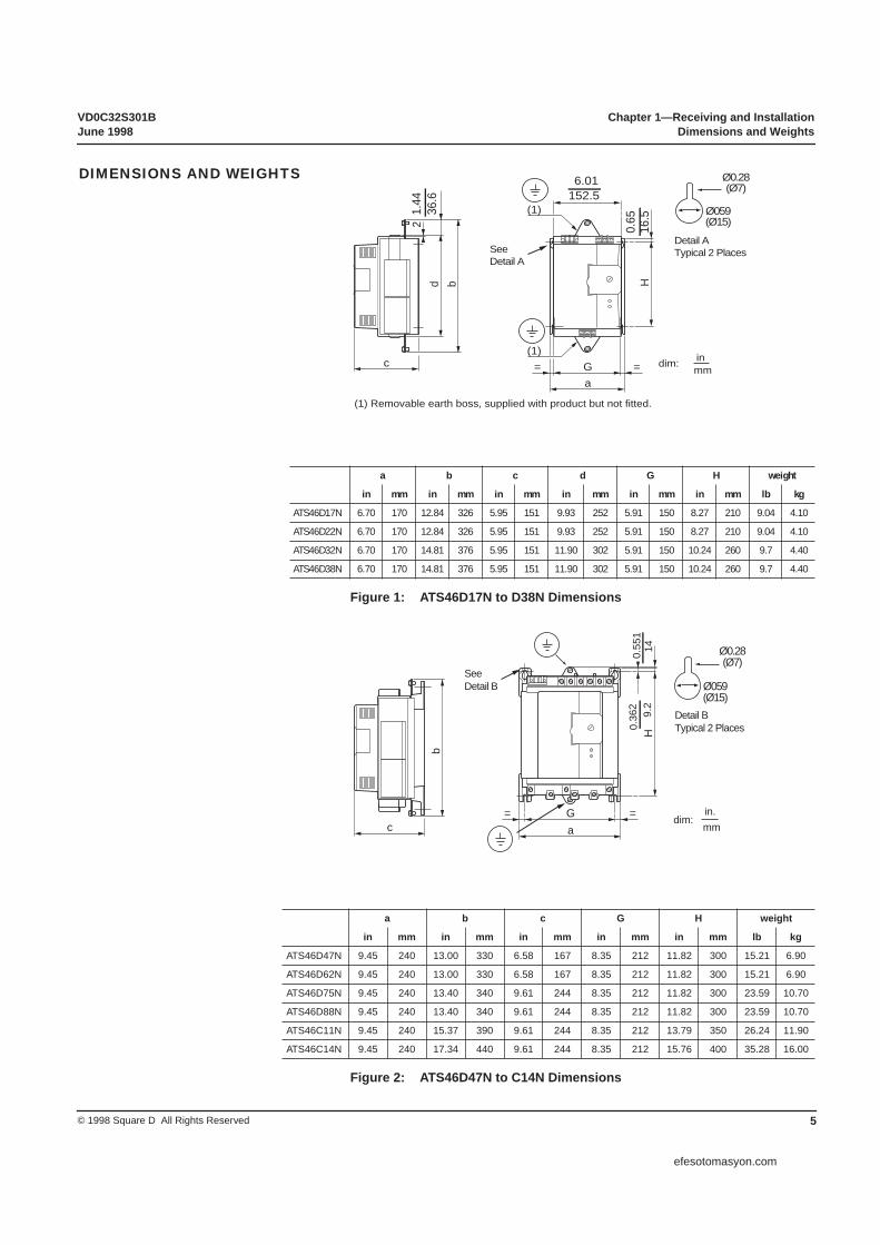
Figure 1: ATS46D17N to D38N Dimensions
Figure 2: ATS46D47N to C14N Dimensions
a b c d G H weight
in mm in mm in mm in mm in mm in mm lb kg
ATS46D17N 6.70 170 12.84 326 5.95 151 9.93 252 5.91 150 8.27 210 9.04 4.10
ATS46D22N 6.70 170 12.84 326 5.95 151 9.93 252 5.91 150 8.27 210 9.04 4.10
ATS46D32N 6.70 170 14.81 376 5.95 151 11.90 302 5.91 150 10.24 260 9.7 4.40
ATS46D38N 6.70 170 14.81 376 5.95 151 11.90 302 5.91 150 10.24 260 9.7 4.40
a b c G H weight
in mm in mm in mm in mm in mm lb kg
ATS46D47N 9.45 240 13.00 330 6.58 167 8.35 212 11.82 300 15.21 6.90
ATS46D62N 9.45 240 13.00 330 6.58 167 8.35 212 11.82 300 15.21 6.90
ATS46D75N 9.45 240 13.40 340 9.61 244 8.35 212 11.82 300 23.59 10.70
ATS46D88N 9.45 240 13.40 340 9.61 244 8.35 212 11.82 300 23.59 10.70
ATS46C11N 9.45 240 15.37 390 9.61 244 8.35 212 13.79 350 26.24 11.90
ATS46C14N 9.45 240 17.34 440 9.61 244 8.35 212 15.76 400 35.28 16.00
b
2 16.536
.6 152.5
G ==a
H
c
(1)
(1)
d
6.01
1.44
0.65
(1) Removable earth boss, supplied with product but not fitted.
inmm
dim:
Ø0.28(Ø7)
Ø059(Ø15)
Detail ATypical 2 PlacesSee
Detail A
DIMENSIONS AND WEIGHTS
G=a
=c
149.
2H
b
0.36
20.
551
dim:in.mm
Ø0.28(Ø7)
Ø059(Ø15)
SeeDetail B
Detail BTypical 2 Places
efesotomasyon.com

Chapter 1—Receiving and Installation VD0C32S301BDimensions and Weights June 1998
© 1998 Square D All Rights Reserved6
Figure 3: ATS46C17N to C32N Dimensions
Figure 4: ATS46C41N to C66N Dimensions
a b c G H weight
in mm in mm in mm in mm in mm lb kg
ATS46C17N 14.34 364 26.99 685 10.60 269 13.36 339 19.70 500 97.02 44.00
ATS46C21N 14.34 364 26.99 685 10.60 269 13.36 339 19.70 500 97.02 44.00
ATS46C25N 14.34 364 26.99 685 10.60 269 13.36 339 19.70 500 97.02 44.00
ATS46C32N 14.34 364 26.99 685 10.60 269 13.36 339 19.70 500 97.02 44.00
a b c G H weight
in mm in mm in mm in mm in mm lb kg
ATS46C41N 15.8 401 37.4 950 13.9 353 13.2 335 31.5 800 123 56
ATS46C48N 15.8 401 37.4 950 13.9 353 13.2 335 31.5 800 137 62
ATS46C59N 15.8 401 37.4 950 13.9 353 13.2 335 31.5 800 137 62
ATS46C66N 15.8 401 37.4 950 13.9 353 13.2 335 31.5 800 137 62
c
153
Hb
Ga
6.0
37414.7
Ø0.28(Ø7)
Ø059(Ø15)
Detail CTypical 2 Places
SeeDetail C
dim:in.mm
246
A2B2C2
135
A1B1C1
c
51 3
Ga
= =
H11
2b
154.
4.5
9 dim:in.mm
Ø0.35(Ø9)
Ø094(Ø24)
Detail DTypical 2 Places
SeeDetail D
efesotomasyon.com

VD0C32S301B Chapter 1—Receiving and InstallationJune 1998 Dimensions and Weights
7© 1998 Square D All Rights Reserved
Figure 5: ATS46C79N to M12N Dimensions
a b c G H weight
in mm in mm in mm in mm in mm lb kg
ATS46C79N 30 766 40 1012 14 353 27.5 700 31.5 800 247 112
ATS46M10N 30 766 40 1012 14 353 27.5 700 31.5 800 273 124
ATS46M12N 30 766 40 1012 14 353 27.5 700 31.5 800 273 124
c Ga
= =
H11
295
0 b
Ø0.35(Ø9)
Ø094(Ø24)
Detail ETypical 2 Places
SeeDetail E
dim:in.mm
efesotomasyon.com

Chapter 1—Receiving and Installation VD0C32S301BHandling the Controller June 1998
© 1998 Square D All Rights Reserved8
Do not remove the ALTISTART 46 (ATS46) controller from the carton until it is at the final installation site. The carton provides protection and prevents damage to the controller’s exterior. Handle the controller carefully after removing it from the carton to avoid damage to the internal components, frame or exterior. Once removed from the carton, the controller can be handled:
• With a hoist. When hoisting the controller, attach a spreader bar to the two lifting rings on top of the controller as shown in Figure 6.
• In a horizontal position, with the back of the controller resting on a pallet.
NOTE: Do not rest unit directly on bus bar connectors.
Figure 6: Hoisting the ATS46 Controller
The serial and model numbers of the ATS46 controller appear on the bar code sticker located on the front right side of the component.
Record the serial number below. This number will assist us in helping you in the future:
HANDLING THE CONTROLLER
HANDLING AND LIFTING HAZARDKeep area below any equipment being lifted clear of all personnel and property. Use lifting method shown in left-hand portion of Figure 6.Failure to follow this instruction can result in death or serious injury.
WARNING
LIFTINGFORCE
45°MAX.
Spreader Bar
LIFTINGFORCE
SERIAL AND MODEL NUMBERS
Serial Number
Model Number
Serial Number: 6W
efesotomasyon.com

VD0C32S301B Chapter 1—Receiving and InstallationJune 1998 Installation Precautions
9© 1998 Square D All Rights Reserved
Follow these precautions when installing the ATS46 controller:
• Voltage and frequency specifications for the input line must match the controller configuration.
• A disconnect switch must be installed between the input line and the controller.
• When using an isolation contactor, certain sequencing must be observed with respect to the run signal supplied to the ATS46 controller. During starting of the controller, closure of the isolation contactor generally should precede or coincide with the application of the controller run command. If line power is not detected at the L1, L2, and L3 terminals of the controller within 500 ms of this run command, a “Phase Failure” fault will occur. The circuit diagrams use this feature of the controller, as displayed in Figures 21 and 22.
• External overcurrent protection devices (OCPD) in the form of fuses or a circuit breaker must be installed on the line-side connections of the ATS46 controller. The maximum recommended OCPD rating, along with the associated controller short-circuit withstand rating, is listed in Appendix A.
INSTALLATION PRECAUTIONS
HAZARDOUS VOLTAGE• Read and understand this manual in its entirety before installing or operating
ATS46 controllers. Installation, adjustment, repair, and maintenance of these controllers must be performed by qualified personnel.
• Disconnect all power before servicing the controller. • DO NOT touch unshielded components or terminal strip screw connections with
voltage present.• Install all covers before applying power or starting and stopping the controller.• User is responsible for conforming to all applicable code requirements with
respect to grounding all equipment. See Figures 1-5 on pages 5-7 for grounding points.
• Many parts in the controller, including printed wiring boards, operate at line voltage. DO NOT TOUCH. Use only electrically-insulated tools while making adjustments.
Before installing the controller:• Disconnect all power.• Place a “DO NOT TURN ON” label on the controller disconnect.• Lock disconnect in open position.Electrical shock will result in death or serious injury.
DANGER
HAZARDOUS VOLTAGE• The solid-state switches of the ATS46 controller power circuit do not provide
complete isolation from the line. Due to leakage currents through the solid-state switches, hazardous voltages can be present on the controller load-side power circuit whenever power is applied to the line side of the controller.
• Disconnect all power before servicing the controller or motor.Electrical shock will result in death or serious injury.
DANGER
efesotomasyon.com
Chapter 1—Receiving and Installation VD0C32S301BInstallation Precautions June 1998
© 1998 Square D All Rights Reserved10
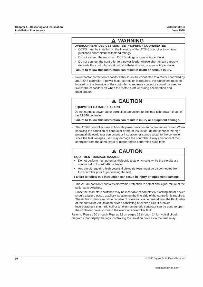
• Power factor correction capacitors should not be connected to a motor controlled by an ATS46 controller. If power factor correction is required, the capacitors must be located on the line-side of the controller. A separate contactor should be used to switch the capacitors off when the motor is off, or during acceleration and deceleration.
• The ATS46 controller uses solid-state power switches to control motor power. When checking the condition of conductor or motor insulation, do not connect the high potential dielectric test equipment or insulation resistance tester to the controller since the test voltages used may damage the controller. Always disconnect the controller from the conductors or motor before performing such tests.
• The ATS46 controller contains electronic protection to detect and signal failure of the solid-state switches.
• Since the solid-state switches may be incapable of completely blocking motor power should a failure occur, auxiliary isolation on the line-side of the controller is required. The isolation device must be capable of operation via command from the Fault relay of the controller. An isolation device consisting of either a circuit breaker incorporating a shunt trip coil or an electromagnetic contactor can be used to open the controller power circuit in the event of a controller fault.
Refer to Figures 20 through Figures 22 on pages 22 through 24 for typical circuit diagrams that display the logic controlling the isolation device via the fault relay.
OVERCURRENT DEVICES MUST BE PROPERLY COORDINATED• OCPD must be installed on the line-side of the ATS46 controller to achieve
published short-circuit withstand ratings.• Do not exceed the maximum OCPD ratings shown in Appendix A.• Do not connect the controller to a power feeder whose short circuit capacity
exceeds the controller short circuit withstand rating shown in Appendix A.Failure to follow this instruction can result in death or serious injury.
WARNING
EQUIPMENT DAMAGE HAZARDDo not connect power factor correction capacitors to the load-side power circuit of the ATS46 controller.Failure to follow this instruction can result in injury or equipment damage.
CAUTION
EQUIPMENT DAMAGE HAZARD• Do not perform high potential dielectric tests on circuits while the circuits are
connected to the ATS46 controller.• Any circuit requiring high potential dielectric tests must be disconnected from
the controller prior to performing the test.Failure to follow this instruction can result in injury or equipment damage.
CAUTION
efesotomasyon.com

VD0C32S301B Chapter 1—Receiving and InstallationJune 1998 Installation Precautions
11© 1998 Square D All Rights Reserved
MOTOR OVERHEATINGFailure of the solid-state switches on the ATS46 controller can cause single-phase operation of the motor.• Use an isolation device consisting of either a circuit breaker equipped with a
shunt trip coil or an electromagnetic contactor to open the line-side of the controller.
• The isolation device must be capable of interrupting motor locked rotor current.• Connect the fault relay of the controller to open the isolation device in the event
of a controller fault.Failure to follow this instruction can result in injury or equipment damage.
CAUTION
BRANCH CIRCUIT CONDUCTOR HAZARDIf System grounding is not adequate to ensure ground fault levels exceed 1300% of motor full load amps (FLA), then this device may not ensure protection of branch circuit conductors. In this case, external ground fault protection must be properly coordinated. Recommended solutions include:• Time delay fuses coordinated to 125% of motor FLA. Fuses listed in
Recommended Component List on page 26 are sized to ensure proper coordination and may be used for applications that do not require start times longer than 50 seconds at 300% current limit or 20 seconds at 500% current limit.
• Equipment ground fault protection. If using a circuit breaker or fuses sized larger than 125% of motor FLA as OCPD, an external ground fault relay or circuit breaker with ground fault detection should be coordinated with controller. An application diagram showing coordination of an equipment ground fault relay is shown in Figure 20 on page 22.
• External overload relay. For multi-motor applications, applications in which motor does not match the controller size, or applications that use a full voltage bypass scheme, an external overload relay can be coordinated to protect conductors from a high-impedance ground fault.
Failure to follow this instruction can result in death or serious injury.
WARNING
efesotomasyon.com

Chapter 1—Receiving and Installation VD0C32S301BMounting Precautions June 1998
© 1998 Square D All Rights Reserved12
Follow these precautions when mounting the ATS46 controller:
• Controllers are open devices and must be installed in suitable enclosures or controlled access areas. The environment around the controller must meet Pollution Degree 3 requirements as defined in NEMA ICS1-1 or IEC 664-1.
• When installation surface is not even, put a spacer behind the controller mounting pads to eliminate gaps. Fastening the controller exterior to an uneven surface may damage the controller.
• When installing in an enclosure, cover the device to prevent metallic debris from falling into the controller.
• The ATS46 controller generates heat and must be properly ventilated. Refer to “Thermal Considerations for Sizing Enclosures” on page 13 to determine power dissipated.
• When several controllers are installed in a control panel, arrange them in a row. Do not stack controllers. Heat generated from the bottom controller can adversely affect the ambient temperature around the top controller.
Degree of protection: NEMA Type 1 (IP23). To ensure adequate air flow inside the controller, follow these guidelines:
• Leave sufficient space around the controller (see Figure 7): A
≥ 2 in (50 mm), B
≥ 4 in (100 mm).
• Provide ventilation.• Ensure sufficient ventilation. If necessary, install a cooling fan with filters.
Figure 7: Ventilation and Clearances
MOUNTING PRECAUTIONS
HAZARDOUS VOLTAGEATS6 controllers are open devices and must be mounted in a suitable enclosure.Electrical shock will result in death or serious injury.
DANGER
CONTROLLER OVERHEATING• Mount the ATS46 controller within ± 15% of vertical.• Do not locate the controller near heat radiating elements.• Electrical current through the controller will result in heat losses that must be
dissipated into the ambient air immediately surrounding the controller. To prevent thermal fault or equipment damage, provide sufficient enclosure cooling and/or ventilation to limit the ambient temperature around the controller.
Failure to follow this instruction can result in injury or equipment damage.
CAUTION
Mounting in General Purpose Metal Enclosure
θ° 40° Cθ° 40° C
B
B
A A
efesotomasyon.com
VD0C32S301B Chapter 1—Receiving and InstallationJune 1998 Remote Mounting Keypad
13© 1998 Square D All Rights Reserved
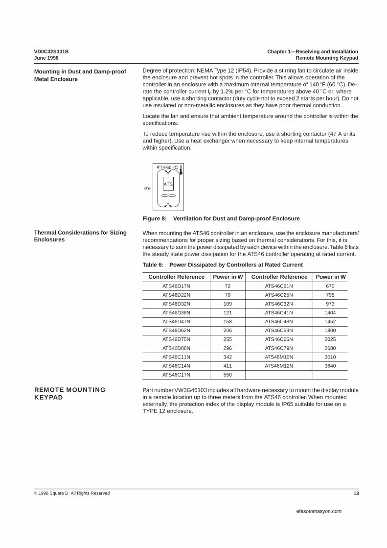
Degree of protection: NEMA Type 12 (IP54). Provide a stirring fan to circulate air inside the enclosure and prevent hot spots in the controller. This allows operation of the controller in an enclosure with a maximum internal temperature of 140
°F (60
°C). De-rate the controller current In by 1.2% per
°C for temperatures above 40
°C or, where applicable, use a shorting contactor (duty cycle not to exceed 2 starts per hour). Do not use insulated or non-metallic enclosures as they have poor thermal conduction.
Locate the fan and ensure that ambient temperature around the controller is within the specifications.
To reduce temperature rise within the enclosure, use a shorting contactor (47 A units and higher). Use a heat exchanger when necessary to keep internal temperatures within specification.
Figure 8: Ventilation for Dust and Damp-proof Enclosure
When mounting the ATS46 controller in an enclosure, use the enclosure manufacturers’ recommendations for proper sizing based on thermal considerations. For this, it is necessary to sum the power dissipated by each device within the enclosure. Table 6 lists the steady state power dissipation for the ATS46 controller operating at rated current.
Table 6: Power Dissipated by Controllers at Rated Current
Part number VW3G46103 includes all hardware necessary to mount the display module in a remote location up to three meters from the ATS46 controller. When mounted externally, the protection index of the display module is IP65 suitable for use on a TYPE 12 enclosure.
Controller Reference Power in W Controller Reference Power in WATS46D17N 72 ATS46C21N 670
ATS46D22N 79 ATS46C25N 795
ATS46D32N 109 ATS46C32N 973
ATS46D38N 121 ATS46C41N 1404
ATS46D47N 158 ATS46C48N 1452
ATS46D62N 206 ATS46C59N 1800
ATS46D75N 255 ATS46C66N 2025
ATS46D88N 296 ATS46C79N 2680
ATS46C11N 342 ATS46M10N 3010
ATS46C14N 411 ATS46M12N 3640
ATS46C17N 550
Mounting in Dust and Damp-proof Metal Enclosure
ATS°e
°i
θ
θ 60 °C
Thermal Considerations for Sizing Enclosures
REMOTE MOUNTING KEYPAD
efesotomasyon.com

Chapter 1—Receiving and Installation VD0C32S301BRemote Mounting Keypad June 1998
© 1998 Square D All Rights Reserved14
efesotomasyon.com

VD0C32S301B Chapter 2—WiringJune 1998
15© 1998 Square D All Rights Reserved
WIRING . . . . . . . . . . . . . . . . . . . . . . . . . . . . . . . . . . . . . . . . . . . . . . . . . . . . . . 16General Wiring Practices . . . . . . . . . . . . . . . . . . . . . . . . . . . . . . . . . . . . . . 16Adaptation to Line Input . . . . . . . . . . . . . . . . . . . . . . . . . . . . . . . . . . . . . . 16Power Connections . . . . . . . . . . . . . . . . . . . . . . . . . . . . . . . . . . . . . . . . . . 16Bus Connection . . . . . . . . . . . . . . . . . . . . . . . . . . . . . . . . . . . . . . . . . . . . . 18
CONTROL CONNECTIONS . . . . . . . . . . . . . . . . . . . . . . . . . . . . . . . . . . . . . . 19Logic Input . . . . . . . . . . . . . . . . . . . . . . . . . . . . . . . . . . . . . . . . . . . . . . . . . 21Logic Outputs. . . . . . . . . . . . . . . . . . . . . . . . . . . . . . . . . . . . . . . . . . . . . . . 21Analog Output . . . . . . . . . . . . . . . . . . . . . . . . . . . . . . . . . . . . . . . . . . . . . . 21
REMOTE MOUNTING KEYPAD . . . . . . . . . . . . . . . . . . . . . . . . . . . . . . . . . . . 22CONTROL CIRCUIT DIAGRAMS . . . . . . . . . . . . . . . . . . . . . . . . . . . . . . . . . . 22RECOMMENDED COMPONENT LIST. . . . . . . . . . . . . . . . . . . . . . . . . . . . . . 26
CHAPTER 2—WIRING
efesotomasyon.com

Chapter 2—Wiring VD0C32S301BWiring June 1998
© 1998 Square D All Rights Reserved16
Good wiring practice requires the separation of control circuit wiring from all power (line and load) wiring. Power wiring to the motor must have the maximum possible separation from all other power wiring. Do not run in the same conduit; this separation reduces the possibility of coupling electrical noise between circuits.
When wiring ATS46 controllers, follow the wiring practices required by national and local electrical codes. In addition, follow these guidelines:
• Use metallic conduit for all controller wiring. Do not run control and power wiring in the same conduit.
• Separate metallic conduits carrying power wiring or low-level control wiring by at least 3 in (8 cm).
• Separate non-metallic conduits or cable trays used to carry power wiring from metallic conduit carrying low-level control wiring by at least 12 in (30.5 cm).
• Cross the metallic conduits and non-metallic conduits at right angles whenever power and control wiring cross.
The control circuit is completely independent of the power circuit. To select control voltage, follow the instructions on the label located on the top of the controller:
• 208-240 V: move terminal cover from position 230 to position 460/500 V and connect single phase voltage supply to terminals C and 230 V.
• 380-415 V: move terminal cover from position 400 to position 460/500 V and connect single phase voltage supply to terminals C and 400 V.
• 440-500 V: check that exposed control terminals are marked C and 460/500 V. If not, move blue terminal cover from 460/500 V terminal and connect single phase voltage supply to terminals C and 460/500 V.
The power circuit adapts automatically to the input line voltage over a range of 208 to 500 V (±10%) for standard controllers.
Table 7: Wire Size and Tightening Torque
ATS46 D17N - D38N
D47N - C14N
C17N - C32N
C41N - C66N
C79N - M12N
POWER CONNECTIONS:
L1 / L2 / L3A1 / B1 / C1T1 / T2 / T3A2 / B2 / C2
Max Wire Size AWG [1] 8 2/0 Bus Bar Bus Bar Bus Bar
Tightening Torquelb-in [2] 15 88 500 500 500
RecommendedMounting Screw [3] n/a n/a 1/2 - 13 1/2 - 13 1/2 - 13
CONTROL POWER CONNECTIONS:
C230400
460/500
Max Wire Size AWG 12 12 12 12 12
Tightening Torquelb-in 10.5 10.5 5.2 5.2 5.2
GROUND CONNECTIONS:
Ground ScrewSupplied M4 M6 M10 M10 M10
Tightening Torquelb-in[4] 15 25.6 238 238 238
[1] Power terminals suitable for use with 75 °C rated conductors; copper only.[2] Power terminals on controllers ATS46D17N through C14N require metric hex wrenches. The appropriate
size hex wrench is provided with these controllers.[3] Requires user-supplied lug and fastener.[4] Requires user-supplied lug.
WIRING
General Wiring Practices
Adaptation to Line Input
Power Connections
efesotomasyon.com

VD0C32S301B Chapter 2—WiringJune 1998 Wiring
17© 1998 Square D All Rights Reserved
Figure 9: Power Connections ATS46D17N to D38N
Figure 10: Power Connections ATS46D47N to C14N
Figure 11: Bus Bar Power Connections ATS46C17N to C32N
3L2 5L3
2T1 4T2 6T3
1L1
A1 1L1 B1 3L2 C1 5L3
A2
2T1
B2
4T2 6T3
C2
A1
1L1 5L3
2T1 4T2 6T3
3L2
B1 C1A2 B2 C2
Ø14mm.55 in
efesotomasyon.com

Chapter 2—Wiring VD0C32S301BWiring June 1998
© 1998 Square D All Rights Reserved18
Figure 12: Bus Power Connection Dimensions: ATS46C41N to C66N
Figure 13: Bus Connection Dimensions: ATS46C79N to M12N
Bus ConnectionDimensions (inches)
TYPICAL
A2 L1 B2 L2 C2 L3
T1 T2 T3
L1 L2 L3
A2 B2 C2
T1 T2 T3
4.8 4.6 4.6
2.5 4.6 4.6
1.3 3.3
6.4
10.0
1.6 .80
.80
1.4
Ø14mm.55 in.
B2A2 C2
4T22T1 6T3
1L1 3L2 5L3
A2 B2 C2 2T1
4T2 6T3
5.9 9.8 9.1
9.5 9.5 3.0
1.6 3.9
0.7
0.7
1.0
2.4
1.0
4.8
7.9
11.5
0.2
Ø14mm
3L21L1 5L3
TYPICAL
.55 in.
efesotomasyon.com
VD0C32S301B Chapter 2—WiringJune 1998 Control Connections
19© 1998 Square D All Rights Reserved
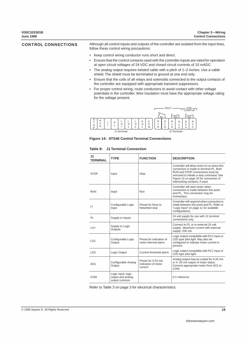
Although all control inputs and outputs of the controller are isolated from the input lines, follow these control wiring precautions:
• Keep control wiring conductor runs short and direct.• Ensure that the control contacts used with the controller inputs are rated for operation
at open circuit voltages of 24 VDC and closed circuit currents of 10 mADC.• The analog output requires twisted cable with a pitch of 1–2 inches. Use a cable
shield. The shield must be terminated to ground at one end only.• Ensure that the coils of all relays and solenoids connected to the output contacts of
the controller are equipped with appropriate transient suppressors.• For proper control wiring, route conductors to avoid contact with other voltage
potentials in the controller. Wire insulation must have the appropriate voltage rating for the voltage present.
Figure 14: ATS46 Control Terminal Connections
Refer to Table 3 on page 3 for electrical characteristics.
Table 8: J1 Terminal Connection
J1TERMINAL TYPE FUNCTION DESCRIPTION
STOP Input Stop
Controller will allow motor to run when this connection is made to terminal PL. Both RUN and STOP connections must be removed to initiate a stop command. See Figure 15 on page 20 for connection of interlocking contacts, if used.
RUN Input Run
Controller will start motor when connection is made between this point and PL. This connection may be momentary.
LI Configurable Logic Input
Preset for force to freewheel stop
Controller will respond when connection is made between this point and PL. Refer to “Logic Input” on page 11 for available configurations.
PL Supply to Inputs 24 volt supply for use with J1 terminal connections only
LO+ Supply to Logic Outputs
Connect to PL or to external 24 volt supply. Maximum current with external supply: 200 mA
LO1 Configurable Logic Output
Preset for indication of motor thermal alarm
Logic output compatible with PLC input or LED type pilot light. May also be configured to indicate motor current is present.
LO2 Logic Output Current threshold alarm Logic output compatible with PLC input or LED type pilot light.
AO1 Configurable Analog Output
Preset for 0-20 mA indication of motor current
Analog output may be scaled for 0-20 mA or 4 -20 mA output of motor status. Connect appropriate meter from AO1 to COM.
COMLogic input, logic output and analog output common
0 V reference
CONTROL CONNECTIONS
STOP
RUN
LI
PL
LO+
LO1
LO2
AO1
COM
R1B
R1D
R1A
R1C
R2A
R2C
J2 TerminalsJ1 Terminals
NC NONO
FAULT ENDSTARTUP
efesotomasyon.com
Chapter 2—Wiring VD0C32S301BControl Connections June 1998
© 1998 Square D All Rights Reserved20
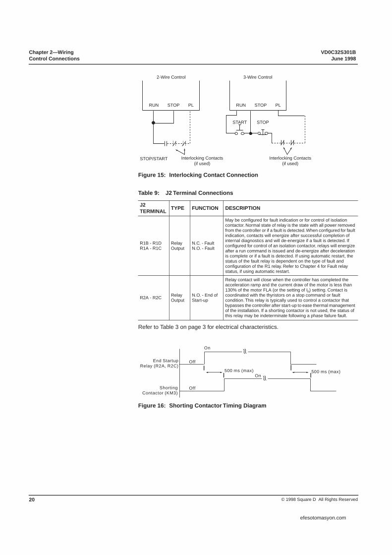
Figure 15: Interlocking Contact Connection
Table 9: J2 Terminal Connections
Refer to Table 3 on page 3 for electrical characteristics.
Figure 16: Shorting Contactor Timing Diagram
J2TERMINAL TYPE FUNCTION DESCRIPTION
R1B - R1DR1A - R1C
RelayOutput
N.C. - FaultN.O. - Fault
May be configured for fault indication or for control of isolation contactor. Normal state of relay is the state with all power removed from the controller or if a fault is detected. When configured for fault indication, contacts will energize after successful completion of internal diagnostics and will de-energize if a fault is detected. If configured for control of an isolation contactor, relays will energize after a run command is issued and de-energize after deceleration is complete or if a fault is detected. If using automatic restart, the status of the fault relay is dependent on the type of fault and configuration of the R1 relay. Refer to Chapter 4 for Fault relay status, if using automatic restart.
R2A - R2C RelayOutput
N.O. - End of Start-up
Relay contact will close when the controller has completed the acceleration ramp and the current draw of the motor is less than 130% of the motor FLA (or the setting of In) setting. Contact is coordinated with the thyristors on a stop command or fault condition. This relay is typically used to control a contactor that bypasses the controller after start-up to ease thermal management of the installation. If a shorting contactor is not used, the status of this relay may be indeterminate following a phase failure fault.
RUN STOP PL
2-Wire Control
RUN STOP PL
3-Wire Control
START STOP
Interlocking Contacts(if used)
Interlocking Contacts(if used)
STOP/START
≈
≈
On
On
Off
Off
500 ms (max)500 ms (max)
End StartupRelay (R2A, R2C)
ShortingContactor (KM3)
efesotomasyon.com

VD0C32S301B Chapter 2—WiringJune 1998 Control Connections
21© 1998 Square D All Rights Reserved
The logic input (LI) may be operated either from the internal supply or an external supply. Figure 17 shows the connections for operating the logic input from an internal supply.
Figure 17: Operating the Logic Inputs from Internal Power Supply
The logic outputs (LO+, LO1, LO2) can be operated from either the internal supply or an external supply. The maximum current with external supply is limited to 200 mA. If the internal supply is used, LO+ must be connected to PL. Figure 18 shows the connection of an external supply for operating the logic outputs
.
Figure 18: Operating the Logic Outputs from External Power Supply
The analog output (AO1) can be configured for 0-20 or 4-20 mA output of the motor current, torque, thermal state, or power factor. Refer to Chapter 3 for configuration of the analog output.
The maximum driving voltage is +12 V with an internal impedance of 800 Ω.
Figure 19shows the connection of an external meter to the analog output.
Figure 19: Analog Outputs
Logic Input
LI PL COM
Customersupplied
24VDC
+ –
Logic Outputs
Customersupplied12-30 VDC
Supply–
+
LO1LO+PL LO2 COM
24VDC
+
–
Analog Output
COM AO1
A
0-20 mA or4-20 mA
800 Ω Customersupplied
efesotomasyon.com

Chapter 2—Wiring VD0C32S301BControl Circuit Diagrams June 1998
© 1998 Square D All Rights Reserved22
The following figures are shown for 2- and 3-wire control of non-reversing and reversing applications. Recommended circuit diagrams include SCR fault isolation for optimal protection of the motor, driven machinery, and operating personnel.
CONTROL CIRCUIT DIAGRAMS
Figure 20: Nonreversing with Shunt Trip Fault Isolation
120V
STOP START
OFF ON
TS1
TR* TRIP RELAY
ST* CB SHUNT TRIP COIL*
TS1
RCR* RUN COMMAND RELAY
TS1
KM3A* SHORTING CONTACTOR PILOT RELAY
TS4
KM3* SHORTING CONTACTOR
M
FU1 FU2
T1 1
KM3 KM3 KM3
3 A1
A2
B1
B2
C1
C2
1/L1
2/T1
3/L2
4/T2
5/L3
6/T3
C
PLLI STOP
500V
RUN
TYPICAL POWER POLE
1
2
7
OR
OR
RCR
R1B R1D
TR
(2 SEC)
MOTOR THERMAL SW
(A) (B)
R1A (R1C FAULT
4
4
4
3
5
6
7 R2A R2C
END START UP
KM3A
1 Control circuit connected for 460 V operation. Reconnect as required for other voltages.
2
3
4
Shorting contactor terminals not providedon D17, D22, D32 OR D38 controllers.
5
6
For shorting contactor operation with D47Nthrough M12N controllers, add KM3 withassociated control circuit.
7
Relay contact located on ATS controller.
Located at motor. Jumper if switch not present.
Use RCR relay logic for ATS 2-wire or 3-wire controlwhen using shorting contactor.
For D47 through C11 controllers using a shorting contactor,pilot relay KM3A is not required. Substitute coil of KM3contactor in place of KM3A pilot relay.
G* RUN
R* POWER ON
SEEBELOW
(C)
RCR
Circuit Breaker* w/Shunt Trip Coil*
3
5
7
1
2
C/T*
GFR
FAULT
OFF ON STOP START
2-WIRE CONTROL W / O AUTO 3-WIRE CONTROL
(A)
(B)HANDOFF
AUTO
2-WIRE CONTROL W / AUTO
USERSUPPLIED
(A)
(C)
(B) (A) (B)
Ground FaultRelay (GFR)*
GFR is not required if OCPD is sized for protectionof branch circuit conductors (see Table 5 on page 26-27).
*
* = User supplied
SOLID STATEOVERLOAD RELAY
efesotomasyon.com

VD0C32S301B Chapter 2—WiringJune 1998 Circuit Diagrams
23© 1998 Square D All Rights Reserved
Figure 21: Nonreversing with Isolation Contactor
120V
TS1
FR*
KM1*
TS1
RCR* RUN COMMAND RELAY
TS1
KM3A* SHORTING CONTACTOR PILOT RELAY
TS4
KM3* SHORTING CONTACTOR
M
FU1 FU2
T1 1
KM3 KM3 KM3* 3
A1
A2
B1
B2
C1
C2
1/L1
2/T1
3/L2
4/T2
5/L3
6/T3
C
STOP
500V
RUN LI
TYPICAL POWER POLE
1
2
RCR
MOTOR THERMAL SW
(A) (B)
R1A R1C FAULT
4
5
6
6
R2A R2C START UP
4
KM3A
1 Control circuit connected for 460 V operation.Reconnect as required for other voltages.
2
3
4
Shorting contactor terminals not provided on D17, D22,D32 or D38 controllers.
5
6
For optional shorting contactor operation with D47N through M12Ncontrollers, add KM3 with associated control circuit.
7
Relay contact located on ATS controller.
Located at motor. Jumper if switch not present.
For D47 through C11 controllers using a shorting contactor,pilot relay KM3A is not required. Substitute coil of KM3 contactorin place of KM3A pilot relay.
KM1* KM1 KM1
TS2
RCR
END
FR
7
Set RCR time slightly longer than the expected decelerationtime from rated speed to zero speed. The time delay RCR contact maybe omitted if the configuration of the R1 relay is changed to isolationcontactor control.
FAULT RELAY
ISOLATIONCONTACTOR
OFF ON STOP START
2-WIRE CONTROL W / O AUTO 3-WIRE CONTROL
R* POWER ON
(A)
(B)HANDOFF
AUTO
2-WIRE CONTROL W / AUTO
USERSUPPLIED
(A)
(C)
(B) (A) (B)
W*
G*
FAULT
RUN KM1
FR
SEEBELOW
(C)
RCR
SW*
PL
L1 L2 L3
FU3 FU4 FU5*
SOLID STATEOVERLOAD RELAY
* = User supplied
efesotomasyon.com
Chapter 2—Wiring VD0C32S301BCircuit Diagrams June 1998
© 1998 Square D All Rights Reserved24
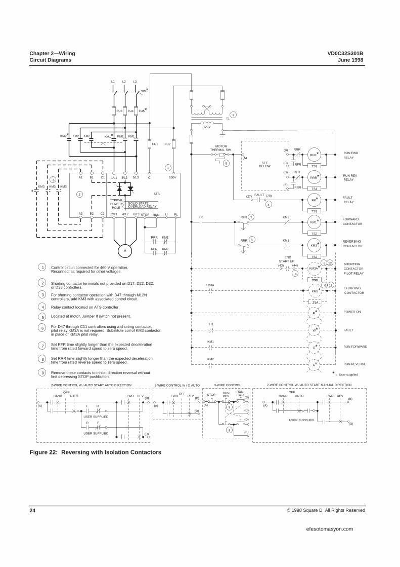
Figure 22: Reversing with Isolation Contactors
120V
TS1
FR*
KM1*
TS1
RFR* RUN FWD RELAY
TS1
KM3A* SHORTING CONTACTOR PILOT RELAY
TS1
TS4
KM3* SHORTING CONTACTOR
M
FU1 FU2
T1 1
KM3 KM3 KM3
6 A1
A2
B1
B2
C1
C2
1/L1
2/T1
3/L2
4/T2
5/L3
6/T3
C 500V
ATS
TYPICALPOWERPOLE
1
2
SEEBELOW
MOTOR THERMAL SW
(A) (C)
RRR
5
6 12
12 6
(43) (44) START UP
4
KM3A
1 Control circuit connected for 460 V operation.Reconnect as required for other voltages.
FU3 FU4 FU5*
2
3
4
Shorting contactor terminals not provided on D17, D22, D32,or D38 controllers.
5
6
For shorting contactor operation with D47 through M12Ncontrollers, add KM3 with associated control circuit.
7
Relay contact located on ATS controller.
8
Located at motor. Jumper if switch not present.
9
For D47 through C11 controllers using a shorting contactor,pilot relay KM3A is not required. Substitute coil of KM3 contactorin place of KM3A pilot relay.
KM1 KM1* KM1
TS2
END
FR
Set RFR time slightly longer than the expected decelerationtime from rated forward speed to zero speed.
FAULT RELAY
FORWARDCONTACTOR
TS1
RRR* RUN REV RELAY
RFR
(B)
(D)
(E)
(27) (28)FAULT
4
7RFR KM2
KM2*
TS2
8RRR KM1
(A)
(D)
(B)HANDOFF
REV
REVERSINGCONTACTOR
RFR
RRR
KM2* KM2 KM2
Set RRR time slightly longer than the expected deceleration time from rated reverse speed to zero speed.
Remove these contacts to inhibit direction reversal withoutfirst depressing STOP pushbutton.
2-WIRE CONTROL W / AUTO START AUTO DIRECTION
R* POWER ON
W*
G*
FAULT
RUN FORWARD KM1
FR
A* RUN REVERSE KM2
(A) (D)
(B)FWD
OFFREV
2-WIRE CONTROL W / O AUTO
STOPRUNFWD
3-WIRE CONTROL
(A) (C)
RUNREV (B)
(D)
(E)
9
9
FWDAUTO
F
R
USER SUPPLIED
USER SUPPLIED
(A)
R
F
(A)
(B)
(D)
HANDOFF
REV
2-WIRE CONTROL W / AUTO START MANUAL DIRECTION
FWDAUTO
USER SUPPLIED
SW*L1 L2 L3
SOLID STATEOVERLOAD RELAY
STOP RUN LI
RRR KM1
KM2 RFR
PL
*
* = User supplied
efesotomasyon.com

VD0C32S301B Chapter 2—WiringJune 1998 Circuit Diagrams
25© 1998 Square D All Rights Reserved
Table 10: Description of Logic for Recommended Circuit Diagrams
Item Name Description
KM1KM1A Isolation Contactor (Forward)
The isolation contactor logic closes KM1 upon a start command and opens KM1 after the stop is complete. The RCR (or RFR and RRR for reversing) are timed contacts that must have a time delay greater than the deceleration ramp time or the dynamic braking time. When a coast stop is selected, the time delay must be set for a time that will allow a complete decay of the motor residual voltage. The isolation contactor will open immediately upon a fault. The pilot relay (KM1A) is required when the KM1 contactor coil exceeds the relay rating.
KM2KM2A Isolation Contactor (Reverse)
Used for reversing applications only, the KM2 must be mechanically interlocked to KM1. A reversing contactor may be used for the combination of KM1 and KM2. In general, the operation of KM2 is identical to KM1. The pilot relay (KM1A) is required when the KM1 contactor coil exceeds the relay rating.
KM3KM3A
Shorting Contactor &Pilot Relay
The shorting contactor is used to reduce the heat dissipated by the controller when the motor is operating at full speed and voltage. The starter provides proper sequencing of this contactor by the “end-start-up” relay. When the start is completed, the shorting contactor will be commanded to close. The starter will continue to monitor the motor thermal state and provide motor overload protection. Upon a stop command, the KM3 contactor will open, transferring the motor current to the SCRs to allow for controlled deceleration if desired. The pilot relay (KM3A) is required when the KM3 contactor coil exceeds the relay rating. Refer to Figure 16 on page 20.
TS Transient Suppressors Transient suppression of all relay and contactor coils (except ST) is recommended to minimize the possibility of electrical interference with the starter electronics and to increase relay contact life.
RCR Run Command Relay
Used in all non-reversing logic (optional in shunt trip) for proper sequencing of contactor logic. When energized, RCR initiates the start sequence. When de-energized, stopping is initiated. Operator controls can be either on/off selector switch, HOA selector switch or start/stop push buttons. RCR remains energized during a fault. Once the fault condition has been cleared, RCR must be de-energized by a “stop” command then re-energized to restart the controller.
RFR Run Forward Relay Used for reversing applications only, this coil duplicates the functionality of RCR for the forward direction and is interlocked with the RFR relay.
RRR Run Reverse Relay Used for reversing applications only, this coil duplicates the functionality of RCR for the reverse direction and is interlocked with the RRR relay.
ST Shunt Trip CoilThis coil is attached to the shunt trip coil on the disconnect and will energize 2 seconds after a starter fault by the TR timer contact. The time delay is to prevent nuisance tripping of the circuit breaker during controller power-up or during line undervoltage conditions.
TR Trip Relay Used in shunt trip circuit breaker logic only; coil energized upon a starter fault.
FR Fault RelayUsed with logic diagrams that use an isolation contactor. The fault relay is energized during normal operation and de-energizes if the starter fault contacts open or if the motor thermal switch (if supplied) opens. FR also provides additional contacts for the starter fault output.
GFR Ground Fault Relay Current-sensitive relay for detection of ground current. If relay is energized, operation of the controller is interrupted by placing in series with the run control relay.
efesotomasyon.com
Chapter 2—Wiring VD0C32S301BCircuit Diagrams June 1998
© 1998 Square D All Rights Reserved26
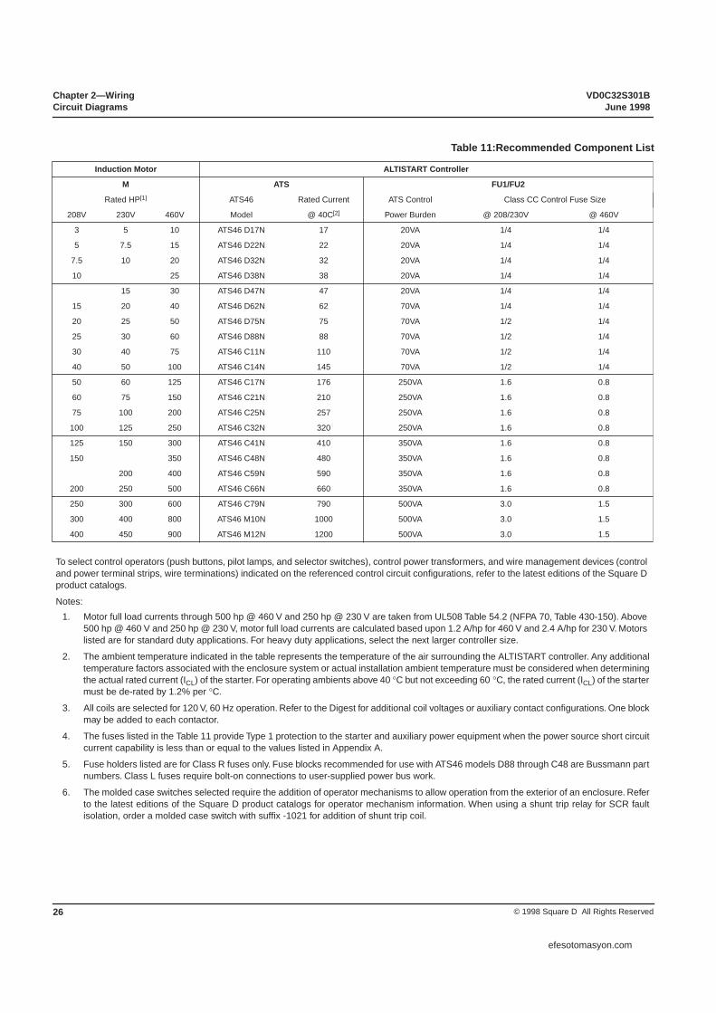
Table 11:Recommended Component List
Induction Motor ALTISTART Controller
M ATS FU1/FU2
Rated HP[1] ATS46 Rated Current ATS Control Class CC Control Fuse Size
208V 230V 460V Model @ 40C[2] Power Burden @ 208/230V @ 460V
3 5 10 ATS46 D17N 17 20VA 1/4 1/4
5 7.5 15 ATS46 D22N 22 20VA 1/4 1/4
7.5 10 20 ATS46 D32N 32 20VA 1/4 1/4
10 25 ATS46 D38N 38 20VA 1/4 1/4
15 30 ATS46 D47N 47 20VA 1/4 1/4
15 20 40 ATS46 D62N 62 70VA 1/4 1/4
20 25 50 ATS46 D75N 75 70VA 1/2 1/4
25 30 60 ATS46 D88N 88 70VA 1/2 1/4
30 40 75 ATS46 C11N 110 70VA 1/2 1/4
40 50 100 ATS46 C14N 145 70VA 1/2 1/4
50 60 125 ATS46 C17N 176 250VA 1.6 0.8
60 75 150 ATS46 C21N 210 250VA 1.6 0.8
75 100 200 ATS46 C25N 257 250VA 1.6 0.8
100 125 250 ATS46 C32N 320 250VA 1.6 0.8
125 150 300 ATS46 C41N 410 350VA 1.6 0.8
150 350 ATS46 C48N 480 350VA 1.6 0.8
200 400 ATS46 C59N 590 350VA 1.6 0.8
200 250 500 ATS46 C66N 660 350VA 1.6 0.8
250 300 600 ATS46 C79N 790 500VA 3.0 1.5
300 400 800 ATS46 M10N 1000 500VA 3.0 1.5
400 450 900 ATS46 M12N 1200 500VA 3.0 1.5
To select control operators (push buttons, pilot lamps, and selector switches), control power transformers, and wire management devices (control and power terminal strips, wire terminations) indicated on the referenced control circuit configurations, refer to the latest editions of the Square D product catalogs.
Notes: 1. Motor full load currents through 500 hp @ 460 V and 250 hp @ 230 V are taken from UL508 Table 54.2 (NFPA 70, Table 430-150). Above
500 hp @ 460 V and 250 hp @ 230 V, motor full load currents are calculated based upon 1.2 A/hp for 460 V and 2.4 A/hp for 230 V. Motors listed are for standard duty applications. For heavy duty applications, select the next larger controller size.
2. The ambient temperature indicated in the table represents the temperature of the air surrounding the ALTISTART controller. Any additionaltemperature factors associated with the enclosure system or actual installation ambient temperature must be considered when determiningthe actual rated current (ICL) of the starter. For operating ambients above 40 °C but not exceeding 60 °C, the rated current (ICL) of the startermust be de-rated by 1.2% per °C.
3. All coils are selected for 120 V, 60 Hz operation. Refer to the Digest for additional coil voltages or auxiliary contact configurations. One blockmay be added to each contactor.
4. The fuses listed in the Table 11 provide Type 1 protection to the starter and auxiliary power equipment when the power source short circuitcurrent capability is less than or equal to the values listed in Appendix A.
5. Fuse holders listed are for Class R fuses only. Fuse blocks recommended for use with ATS46 models D88 through C48 are Bussmann partnumbers. Class L fuses require bolt-on connections to user-supplied power bus work.
6. The molded case switches selected require the addition of operator mechanisms to allow operation from the exterior of an enclosure. Referto the latest editions of the Square D product catalogs for operator mechanism information. When using a shunt trip relay for SCR faultisolation, order a molded case switch with suffix -1021 for addition of shunt trip coil.
efesotomasyon.com

VD0C32S301B Chapter 2—WiringJune 1998 Circuit Diagrams
27© 1998 Square D All Rights Reserved
for Circuit Diagrams
Contactors [3, 7, 10, 12] Disconnect [11]
KM1 KM2 KM3 Fusible Disconnect
Isolation Contactor Reversing Contactor (8)
MechanicalInterlock Shorting Contactor Power Fuses
Class/Rating (4) Fuse Block (5) Molded Case Switch (6)
LC1 D1211G6 LC1 D1211G6 (9) N/A RK5 / 20 9080 FB3611R FHL36000M
LC1 D1811G6 LC1 D1811G6 (9) N/A RK5 / 30 9080 FB3611R FHL36000M
LC1 D3211G6 LC1 D3211G6 (9) N/A RK5 / 40 9080 FB3621R FHL36000M
LC1 D3211G6 LC1 D3211G6 (9) N/A RK5 / 45 9080 FB3621R FHL36000M
LC1 D4011G6 LC1 D4011G6 (9) LC1 D4011G6 RK5 / 60 9080 FB3621R FHL36000M
LC1 D5011G6 LC1 D5011G6 (9) LC1 D5011G6 RK5 / 70 9080 FB3631R FHL36000M
LC1 D6511G6 LC1 D6511G6 (9) LC1 D6511G6 RK5 / 90 9080 FB3631R FHL36000M
LC1 D8011G6 LC1 D8011G6 (9) LC1 D8011G6 RK5 / 110 6R200A3BE FHL36000M
LC1 D8011G6 LC1 D8011G6 (9) LC1 D8011G6 RK5 / 150 6R200A3BE KHL36000M
LC1 F150G6 LC1 F150G6 LA9 FF970 LC1 F150G6 RK5 / 175 6R200A3BE KHL36000M
LC1 F150G6 LC1 F150G6 LA9 FF970 LC1 F150G6 RK5 / 200 6R200A3BE KHL36000M
LC1 F185G6 LC1 F185G6 LA9 FG970 LC1 F185G6 RK5 / 250 6R400A3B KHL36000M
LC1 F265G7 LC1 F265G7 LA9 FJ970 LC1 F265G7 RK5 / 350 6R400A3B LHL36000M
LC1 F330G7 LC1 F330G7 LA9 FJ970 LC1 F330G7 RK5 / 400 6R400A3B LHL36000M
LC1 F400F7 LC1 F400F7 LA9 FJ970 LC1 F400F7 RK5 / 500 6R600A3B LHL36000M
LC1 F400F7 LC1 F400F7 LA9 FJ970 LC1 F400F7 RK5 / 600 6R600A3B MHL360006M
LC1 F500F7 LC1 F500F7 LA9 FJ970 LC1 F500F7 L / 650 (5) MHL360008M
LC1 F500F7 LC1 F500F7 LA9 FJ970 LC1 F500F7 L / 800 (5) MHL360008M
LC1 F630F7 LC1 F630F7 LA9 FL970 LC1 F630F7 L / 1000 (5) MHL36000M
LC1 F630F7 LC1 F630F7 LA9 FL970 LC1 F630F7 L / 1200 (5) MHL36000M
LC1 F780F7 LC1 F780F7 LA9 FX970 LC1 F780F7 L / 1600 (5) NCL3600012M
Notes: (continued)
7. Power terminals are not included with LC1-F or LC1-B contactors. Refer to the latest editions of the Square D product catalogs foradditional ordering information.
8. Reversing contactors for C15 through M12 controllers must be assembled from components. Parts quantities for a basic contactorassembly, minus the power connection links and terminals, are indicated before each part number. Refer to the latest editions of the SquareD product catalogs for power connector link and terminal kits. Reversing contactor interlock units used for the C82 through M12 controllersare designed for vertical interlocking of the individual contactors. Horizontally interlocked contactors are used for U70 through C58controllers.
9. The “D” Line Contactor is available as a reversing configuration. For these applications, change the KM1 part number prefix from LC1- toLC2- to order the KM1 and KM2 combination complete with mechanical interlocks.
10. The use of transient suppressors across all contactor coils is recommended. Refer to the latest editions of the Square D product catalogsfor selection of transient suppressors.
11. According to the National Electric Code, branch circuit overcurrent protection must be provided for each controller. Short circuit protectivedevices recommended in this table are within NEC requirements. Refer to Appendix A for maximum protective device ratings.
12. Contactors are sized for AC1 duty and coordinated for short circuit withstand capability when using the overcurrent protective devicerecommended in the appendix.
efesotomasyon.com

Chapter 2—Wiring VD0C32S301BCircuit Diagrams June 1998
© 1998 Square D All Rights Reserved28
efesotomasyon.com

VD0C32S301B Chapter 3—Application and ProtectionJune 1998
29© 1998 Square D All Rights Reserved
SOFT START APPLICATION. . . . . . . . . . . . . . . . . . . . . . . . . . . . . . . . . . . . . . . . . . . 30Standard Duty Applications . . . . . . . . . . . . . . . . . . . . . . . . . . . . . . . . . . . . . . . . . . 30Heavy Duty Applications . . . . . . . . . . . . . . . . . . . . . . . . . . . . . . . . . . . . . . . . . . . . 30Reduced Torque . . . . . . . . . . . . . . . . . . . . . . . . . . . . . . . . . . . . . . . . . . . . . . . . . . 30
MODES OF STARTING . . . . . . . . . . . . . . . . . . . . . . . . . . . . . . . . . . . . . . . . . . . . . . . 31Acceleration Ramp . . . . . . . . . . . . . . . . . . . . . . . . . . . . . . . . . . . . . . . . . . . . . . . . 31Torque Limit . . . . . . . . . . . . . . . . . . . . . . . . . . . . . . . . . . . . . . . . . . . . . . . . . . . . . 32Current Limit . . . . . . . . . . . . . . . . . . . . . . . . . . . . . . . . . . . . . . . . . . . . . . . . . . . . . 32Voltage Boost . . . . . . . . . . . . . . . . . . . . . . . . . . . . . . . . . . . . . . . . . . . . . . . . . . . . 32
MODES OF STOPPING . . . . . . . . . . . . . . . . . . . . . . . . . . . . . . . . . . . . . . . . . . . . . . . 32Deceleration Ramp . . . . . . . . . . . . . . . . . . . . . . . . . . . . . . . . . . . . . . . . . . . . . . . . 32InTele Braking . . . . . . . . . . . . . . . . . . . . . . . . . . . . . . . . . . . . . . . . . . . . . . . . . . . . 33
MOTOR PROTECTION AND DIAGNOSTICS . . . . . . . . . . . . . . . . . . . . . . . . . . . . . . 33Thermal Overload Protection . . . . . . . . . . . . . . . . . . . . . . . . . . . . . . . . . . . . . . . . 33Excessive Cycling Prevention . . . . . . . . . . . . . . . . . . . . . . . . . . . . . . . . . . . . . . . . 36Stall and Steady State Protection . . . . . . . . . . . . . . . . . . . . . . . . . . . . . . . . . . . . . 37Protection from Line Faults . . . . . . . . . . . . . . . . . . . . . . . . . . . . . . . . . . . . . . . . . . 38
CONTROLLER I/O CONFIGURATION . . . . . . . . . . . . . . . . . . . . . . . . . . . . . . . . . . . 38Faults/ISO Contactor Control Relays . . . . . . . . . . . . . . . . . . . . . . . . . . . . . . . . . . 38End of Start-Up Relay . . . . . . . . . . . . . . . . . . . . . . . . . . . . . . . . . . . . . . . . . . . . . . 38Logic Output . . . . . . . . . . . . . . . . . . . . . . . . . . . . . . . . . . . . . . . . . . . . . . . . . . . . . 38Analog Output . . . . . . . . . . . . . . . . . . . . . . . . . . . . . . . . . . . . . . . . . . . . . . . . . . . . 39Logic Input. . . . . . . . . . . . . . . . . . . . . . . . . . . . . . . . . . . . . . . . . . . . . . . . . . . . . . . 39
DISPLAY OF MOTOR VALUES . . . . . . . . . . . . . . . . . . . . . . . . . . . . . . . . . . . . . . . . . 39
CHAPTER 3—APPLICATION AND PROTECTION
efesotomasyon.com
Chapter 3—Application and Protection VD0C32S301BJune 1998
© 1998 Square D All Rights Reserved30
The key to applying a soft start successfully is matching the load to the motor capability while starting with reduced voltage applied. The ALTISTART 46 is factory preset to start the motor for which the controller is rated for standard duty applications. A switch is located behind the removable keypad that can be toggled from standard duty to heavy duty application presets.
For standard duty applications, the ALTISTART controller is preset for Class 10 overload protection, a 300% current limit and 10 second acceleration ramp. Typical standard duty applications include most fans and centrifugal pumps. Other standard duty applications include machines such as screw type compressors or conveyors that are started with light or no load.
At the standard duty default settings, 10 starts per hour may be achieved for a maximum of 23 seconds per start without tripping. The standard duty horsepower rating of the controller is listed on the device nameplate. Applications requiring long start times, high starting torque, or frequent starting and stopping may require de-rating of the controller or the use of a shorting contactor to bypass the controller once the motor is up to speed.
For heavy duty applications, the ALTISTART controller is preset for Class 20 overload protection, a 350% current limit and 15 second acceleration ramp. Heavy duty applications include high inertia loads or other loads requiring long acceleration times. Some examples of heavy duty applications include grinders, crushers, and presses as well as high inertia fans and saws.
For heavy duty applications, the controller must be de-rated by one size. When the duty selector switch is toggled to heavy duty mode, the default motor current setting is adjusted to the rated current of the next lower common motor size. At the heavy duty default settings, 5 starts per hour may be achieved for a maximum of 46 seconds per start without tripping.
If a shorting contactor is used to bypass the SCRs after starting, the controller may be used for heavy duty applications at its standard duty rating. Refer to chapter 3 for additional information regarding the factory presets.
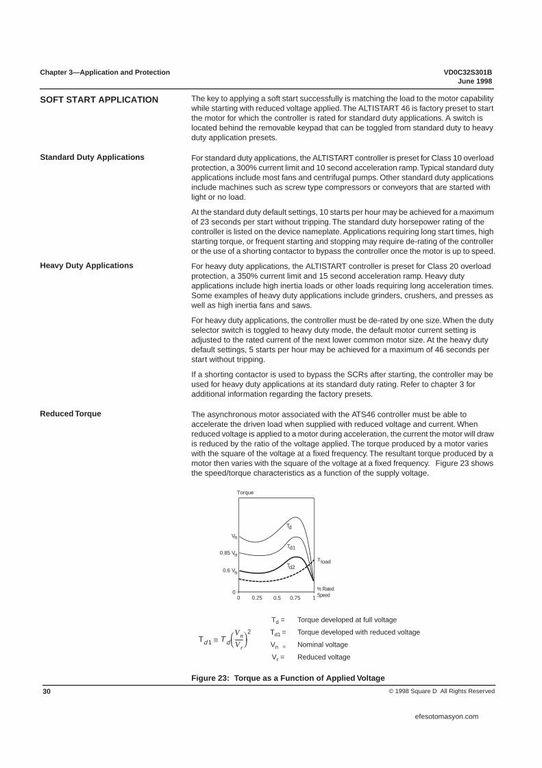
The asynchronous motor associated with the ATS46 controller must be able to accelerate the driven load when supplied with reduced voltage and current. When reduced voltage is applied to a motor during acceleration, the current the motor will draw is reduced by the ratio of the voltage applied. The torque produced by a motor varies with the square of the voltage at a fixed frequency. The resultant torque produced by a motor then varies with the square of the voltage at a fixed frequency. Figure 23 shows the speed/torque characteristics as a function of the supply voltage.
Figure 23: Torque as a Function of Applied Voltage
SOFT START APPLICATION
Standard Duty Applications
Heavy Duty Applications
Reduced Torque
00 0.25 0.5 0.75 1
T
V
0.85 V
0.6 V
Torque
load
n
n
n
% RatedSpeed
T
T
T
d
d1
d2
Td 1 T dVnVr------⎝ ⎠
⎛ ⎞2
≅
Td = Torque developed at full voltage
Td1 = Torque developed with reduced voltage
Vn = Nominal voltage
Vr = Reduced voltage
efesotomasyon.com

VD0C32S301B Chapter 3—Application and ProtectionJune 1998 Modes of Starting
31© 1998 Square D All Rights Reserved
A “soft start” progressively increases voltage to the motor. By ramping the voltage, the ATS46 controller limits the amount of current the motor can draw during starting to a user-defined setting. Figure 24 shows the speed/torque characteristics of a motor as a function of starting current. The ATS46 controller provides optimal acceleration by ramping the acceleration torque within the envelope of curve Td1.
Figure 24: Torque as a Function of Starting Current
The ATS46 controller is factory preset for simple, out-of-the-box operation in many applications. The factory preset provides a 10-second acceleration ramp with 300% of the factory preset nominal current.
TCS™ (Torque Control System) ramp is the most widely used acceleration ramp. It is ideal for applications that require a smooth, stepless start. The ATS46 controller uses patented technology to calculate the motor torque continuously . Basing the TCS ramp on the motor torque provides constant acceleration torque ideally suited for most fans, centrifugal pumps, or other variable torque loads.
A torque ramp provides a higher level of control than is available with typical voltage ramping or current limiting soft starters. As shown in the diagrams below, torque ramping compared to a current limited start can provide a more linear speed ramp, reduces the surge of acceleration typical for most soft starts and minimizes the motor temperature rise by reducing the amount of current drawn during acceleration.
Figure 25: Torque Ramp vs. Current Limit Starting
The torque ramp time, or the time to increase from zero torque to the nominal torque of the motor, may be adjusted from 1 to 60 seconds. The initial torque applied is preset for 10% of the motor nominal torque, but may be adjusted from 0 to 100% for maximum flexibility and adaptability for varying loads.
00 0.25 0.5 0.75 1
load
T
I
T
T d1
I d1
% RatedSpeed
Current
I Starting current at full voltage(locked rotor amps)
Current limit during Soft Start
=
=Id1
d
d
d
MODES OF STARTING
Acceleration Ramp
Speed
Time
Torque Ramp
Current Limit
Current Limit
Torque Ramp
Time
Current
efesotomasyon.com

Chapter 3—Application and Protection VD0C32S301BModes of Stopping June 1998
© 1998 Square D All Rights Reserved32
As Figure 26 illustrates, the maximum motor torque may be limited to between 10 and 100% of the motor nominal torque. This feature is primarily used to limit acceleration of high inertia or constant torque applications. If used, the torque limit combines with the acceleration ramp and initial torque settings to provide a highly customized acceleration torque profile.
Figure 26: Acceleration with Torque Limit
Current limit starting is used primarily in high-horsepower applications of limited system capacity. The current limit is adjustable from 150 to 500% of the controller current rating. The current limit setting is always active during start up and overrides all other settings. When the user-defined current limit setting is reached, the torque ramp adjusts to prevent excess current draw.
When starting, if the torque is too low due to dry friction, stiff mechanism, or high inertia, the boost function allows the motor to develop increased torque to initiate motor shaft rotation. As Figure 27 shows, the voltage applied during the boost may be adjusted from 50 to 100% of the motor nominal voltage and is applied for 5 cycles of mains power.
Figure 27: Boost Function
The ATS46 controller can be set for freewheel stop, deceleration ramp, or dynamic braking. The default setting is freewheel stop, which removes all voltage from the motor terminals after a stop command. The time the motor takes to coast to rest depends on inertia and resistive torque of the driven load.
Deceleration ramping uses the same principles of the acceleration ramp, providing a gradual deceleration. This feature is typically used in pumping applications to prevent hydraulic shocks or water hammer, which may occur if the motor decelerates too quickly. As shown in Figure 28 on page 33, when deceleration ramping is selected, the ramp time may be adjusted from 1 to 60 seconds. The torque threshold at which the ramp ends may also be adjusted from 0 to 100% of nominal torque.
Torque Limit
100 %
80 %
t(s)
Tn
Acceleration setting
Torque limit
Initialtorque10%
Current Limit
Voltage Boost
50 %
100 ms
100 %
t(s)
T
T
Following accelerationramp
n
n
V
V
n
Boost
d
MODES OF STOPPING
Deceleration Ramp
efesotomasyon.com

VD0C32S301B Chapter 3—Application and ProtectionJune 1998 Motor Protection and Diagnostics
33© 1998 Square D All Rights Reserved
Once the torque reaches the threshold value, the controller changes to freewheel mode and the motor coasts to a stop. The threshold setting is useful in pumping applications, which do not require continued deceleration control once the check valve has closed. If the torque is below the threshold setting at a given stop command, controlled deceleration is not activated and the controller changes to freewheel stop.
Figure 28: Torque Ramp During Deceleration
InTele Braking is available for applications that require faster than freewheel deceleration time. Impulse braking decelerates the motor to 20% of the rated speed; DC Injection completes the deceleration. The braking level may be adjusted from 0 to 100% to provide gradual ramp. To customize the deceleration ramp, adjust the duration of the DC injection from 20 to 100% of the impulse braking time. If InTele Braking is selected, the controller is preset for 50% braking torque level with a change to DC injection at 20% speed for 20% duration.
Figure 29: InTele Braking
The ATS46 controller provides state-of-the-art motor protection. On controllers rated 47 A and higher, motor protective features are available even if a shorting contactor is used to bypass the SCRs after the motor is up to speed. To assist with troubleshooting, the 3-digit LCD displays fault status codes. The controller memory registers and maintains the previous 5 faults, even following power loss.
The ATS46 controller is a UL Listed motor controller with integrated motor and controller thermal protection. The motor and controller temperature are continuously calculated based on the controller nominal current and the current that is actually drawn. An electronic circuit, which stores the thermal state of the motor even if the supply power is disconnected, simulates the cooling curve.
Overload of any kind over any duration can cause the motor temperature to rise. As Figure 30 shows, the ATS46 controller creates a digital model of the motor temperature based on two thermal images. The first (T1) represents the level of temperature rise corresponding to “iron” (motor frame). The second (T2) represents the temperature rise of “copper” (stator, windings). For each thermal image, two levels of alarm are detected.
0 %
20 %
100 %
t(s)
Torquethreshold
Deceleration setting10 60
T
InTele™ Braking
20 %
100 %
TimeImpulse braking DC injection
Speed
Less gradualbraking
Level to switch toDC injection
More gradualbraking
MOTOR PROTECTION AND DIAGNOSTICS
Thermal Overload Protection
efesotomasyon.com

Chapter 3—Application and Protection VD0C32S301BMotor Protection and Diagnostics June 1998
© 1998 Square D All Rights Reserved34
An overload pre-alarm is signaled by logic output LO1 when the motor has exceeded its nominal temperature rise threshold. A pre-alarm is signaled when the thermal state exceeds 105% for T1 and/or 130% for T2.
A thermal fault signal stops the motor when the temperature rise exceeds the critical threshold. A thermal fault is signaled by relay R1 when the motor thermal state exceeds 110% for T1 and 140% for T2.
Figure 30: Thermal Trip Curves
The ATS46 controller is preset to provide Class 10 overload protection for standard duty applications. The ATS46 controller can be adjusted to provide Class 2, 10A, 10, 15, 20, 25, or 30 overload protection, as necessary. Class 2 protection is available for applications such as submersible pumps, where very tight control of motor temperature is required. Class 30 protection is available for applications such as high inertia loading, where a longer than normal starting time is required to accelerate the load to full speed. In addition, the internal overload protection may be disabled if motor protection is provided externally.
The various thermal overload protection classes are defined to meet the standards of IEC 947-4-2 for starting from both cold and hot states. Starting from a cold state is defined as the stabilized motor thermal state when the motor is off. Figure 31 shows the approximate trip times for starting from a cold state.
1 2 3 4 5I/I
t
5 s
60 mn
5 mn T1
T2
1.05 1.11
Pre-alarm
n
efesotomasyon.com

VD0C32S301B Chapter 3—Application and ProtectionJune 1998 Motor Protection and Diagnostics
35© 1998 Square D All Rights Reserved
Figure 31: Cold Start Curves
Starting from a hot state is defined as the stabilized motor thermal state when the motor has been running at full load capacity. Figure 32 on page 36 shows the approximate trip times for starting from a hot state.
0.5
1
10
100
1000
10000t(s)
8.00I/I
7.507.006.506.005.505.004.504.003.503.002.502.001.51.12
Class 30Class 25Class 20
Class 15
Class 10
Class 10A
Class 2
n
efesotomasyon.com

Chapter 3—Application and Protection VD0C32S301BMotor Protection and Diagnostics June 1998
© 1998 Square D All Rights Reserved36
Figure 32: Hot Start Curves
To avoid excessive starting and stopping, adjust the time before starting. The range of adjustment is between 0 and 999 seconds. When using a freewheel stop, the ATS46 controller will not accept a new start command during the time after a STOP command is issued and before the motor starts. When using controlled deceleration, a new START command will not be accepted until: the time elapses after the soft stop; or InTeleBraking is complete. The factory preset of two seconds ensures de-magnetization is complete before motor restart.
Figure 33: Time before starting
1
10
100
1000
10000t(s)
Class 30Class 25Class 20
Class 15
Class 10
Class 10A
Excessive Cycling Prevention
STOP STOPEnd of soft stop or braking
tbS tbS
Freewheel Stop Controlled Stop
efesotomasyon.com
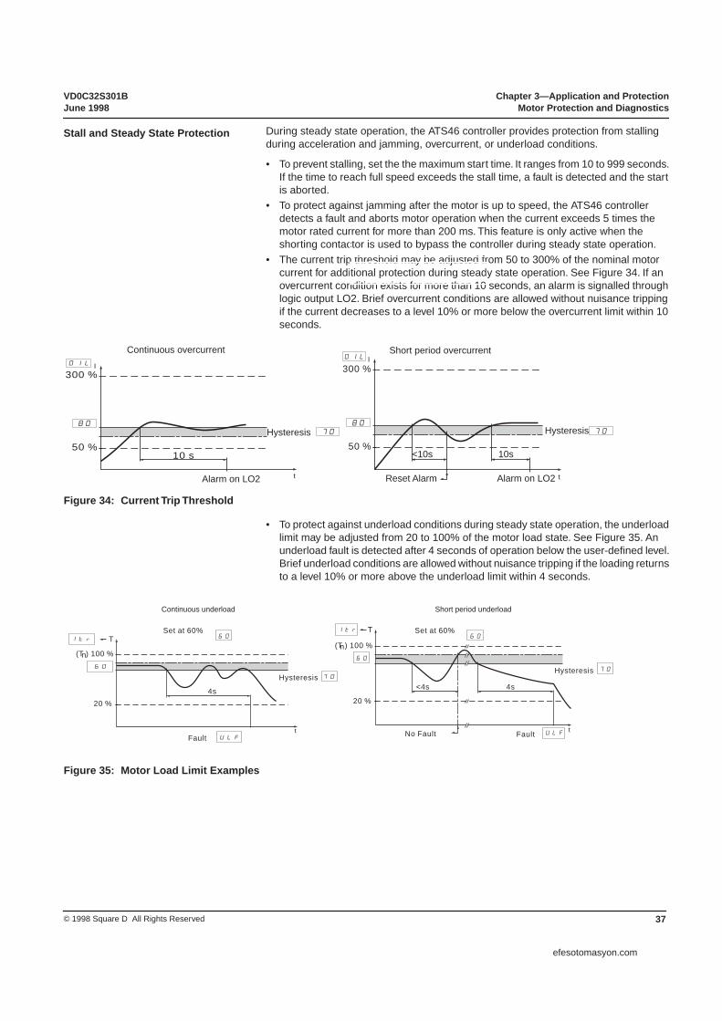
VD0C32S301B Chapter 3—Application and ProtectionJune 1998 Motor Protection and Diagnostics
37© 1998 Square D All Rights Reserved
Figure 34: Current Trip Threshold
50 %
300 %
10 s
t
IOIL
50 %
300 %
t
IOIL
Reset Alarm Alarm on LO2Alarm on LO2
Hysteresis 7080 80
Hysteresis 70
Short period overcurrentContinuous overcurrent
10s<10s
• To protect against underload conditions during steady state operation, the underload limit may be adjusted from 20 to 100% of the motor load state. See Figure 35. An underload fault is detected after 4 seconds of operation below the user-defined level. Brief underload conditions are allowed without nuisance tripping if the loading returns to a level 10% or more above the underload limit within 4 seconds.
Figure 35: Motor Load Limit Examples
tULF
60
70
ltr
20 % 20 %
(T ) 100 %(T ) 100 %
t
TT
4s4s
Set at 60%
HysteresisHysteresis
No Fault FaultFault
ltr
60
70
60Set at 60%
60
ULF
Short period underloadContinuous underload
<4s
nn
During steady state operation, the ATS46 controller provides protection from stalling during acceleration and jamming, overcurrent, or underload conditions.
• To prevent stalling, set the the maximum start time. It ranges from 10 to 999 seconds. If the time to reach full speed exceeds the stall time, a fault is detected and the start is aborted.
• To protect against jamming after the motor is up to speed, the ATS46 controller detects a fault and aborts motor operation when the current exceeds 5 times the motor rated current for more than 200 ms. This feature is only active when the shorting contactor is used to bypass the controller during steady state operation.
• The current trip threshold may be adjusted from 50 to 300% of the nominal motor current for additional protection during steady state operation. See Figure 34. If an overcurrent condition exists for more than 10 seconds, an alarm is signalled through logic output LO2. Brief overcurrent conditions are allowed without nuisance tripping if the current decreases to a level 10% or more below the overcurrent limit within 10 seconds.
Stall and Steady State Protection
efesotomasyon.com
Chapter 3—Application and Protection VD0C32S301BController I/O Configuration June 1998
© 1998 Square D All Rights Reserved38
The ATS46 controller provides protection from line faults while allowing for continued operation when supplied with typical industrial power that may contain minor disturbances. The ATS46 controller interrupts motor operation if the following fault conditions are detected:
• Mains supply failure greater than 500 ms.• Loss of motor phase or shorting contactor connection.• Supply frequency outside limits upon initialization. For 60 Hz operation, the supply
frequency must be between 56.4 and 63.6 Hz. For 50 Hz operation, the supply frequency must be between 47 and 52.5 Hz.
Phase reversal may be selected to prevent operation if the supply phase rotation does not correspond to the specified rotation direction.
The ATS46 controller also trips on overcurrent due to a short circuit at the controller, a shorted SCR, or a shorting contactor malfunction. Although the controller may detect these faults, the user must install an external means of automatically disconnecting the motor from the line supply. This external disconnect provides protection for the motor, driven machinery, and operating personnel.
The ATS46 controller provides several inputs and outputs that can be adapted to a variety of functions. The controller is preset at the factory to meet the requirements of most applications. The functions of the inputs, outputs, and optional configurations are described below.
One normally opened and one normally closed contact is supplied for indication of fault or control of an isolation contactor. In the default mode, R1 contacts change state if a fault is detected. The contacts are in their normal state upon application of control power. Once the self diagnostic check is completed, if no fault is found, the fault relay energizes. The fault contacts will change to their de-energized state if a fault condition is detected, or if control power is lost.
If configured for control of an isolation contactor, the R1 contacts stay in their normal state until a run command is initiated. The R1 contacts then stay energized until a fault condition is detected or until deceleration is complete. This allows the user to coordinate an isolation contactor to disconnect the motor from the line under a fault condition or when the motor is not in use.
A normally open relay is provided to allow for easy integration of a shorting contactor. The end of start-up relay closes once the motor has reached full speed and opens following a fault condition or after a stop command is initiated. Following a stop command, the end of start-up contact is used to drop out the shorting contactor so that deceleration control may be used if selected.
If a shorting contactor is going to be used to bypass the SCRs after starting is complete, the shorting contactor must close within 500 msec of detection of full speed operation. If a shorting contactor is used, the end of start-up relay must be used to coordinate operation of the shorting contactor.
Two logic outputs compatible with PLC inputs are provided on the ATS46 controller. The factory preset for LO1 indicates a thermal pre-alarm. In this configuration, the logic output changes to state 1 when a motor thermal overload pre-alarm has been reached, and stays high until the thermal fault has cleared. When a pre-alarm condition exists, corrections should be made to the process to prevent an actual overload fault condition, which requires down time for motor cooling.
The LO1 output may also be configured for motor power indication. In this configuration, the output changes to state 1 whenever the motor current is present.
A second logic output, LO2, is provided to signal an overcurrent alarm. If overcurrent detection is not selected, LO2 is inactive.
Protection from Line Faults
CONTROLLER I/O CONFIGURATION
Faults/Iso Contactor Control Relays
End of Start-up Relay
Logic Output
efesotomasyon.com

VD0C32S301B Chapter 3—Application and ProtectionJune 1998 Display of Motor Values
39© 1998 Square D All Rights Reserved
An analog output is provided that indicates motor status. The A1 output can be configured for 0-20 mA or 4-20 mA output. The analog output is factory preset to indicate motor current, but may be configured to indicate motor torque, thermal state, or power factor.
The logic input is factory pre-set to force the controller to a freewheel stop. Alternate configurations include external fault, force to local control, control of cascading motors, and thermal overload reset.
• Force to Freewheel: Overrides controlled deceleration if selected.• External Fault: Interrupts controller operation following an input from an external fault
detection device.• Local Control: If using the communications option (VW3-G46301), the logic input
must be configured for local control. When configured for local control, activating the logic input is required to switch from remote to local operation.
• Control of Cascading Motors: When initiated, allows for control of several motors.• Thermal Overload Reset: The logic input may be configured to require operator
acknowledgment of a thermal overload condition. In this configuration, the logic input must be changed to state 1 after the thermal fault has cleared before the motor may be re-started.
• Fault Reset: The logic input may also be configured to require operator acknowledgement of all faults. In this configuration, the logic input must be changed to state 1 after a fault has cleared before the motor may be restarted.
The ATS46 controller provides a three-digit LCD display that can be set up to display the controller and motor characteristics, as described in Table 12.
Table 12: LCD Display Descriptions
LCD DIsplay Description
Controller Status Displays a ready, run or fault status.
Motor Current Displays the motor current, from 0 to 6000 amps. Active during acceleration and steady state.
Motor Load State Displays the motor torque production, from 0 to 150% of the nominal motor torque.
Active Power Displays the active power as a percentage of the motor nominal power.
Motor Thermal State Displays the thermal state of the motor, from 0 to 120% of the motor full load amp setting.
Motor Power Factor Displays the motor power factor, from 0.1 to 1.
Analog Output
Logic Input
DISPLAY OF MOTOR VALUES
efesotomasyon.com

Chapter 3—Application and Protection VD0C32S301BDisplay of Motor Values June 1998
© 1998 Square D All Rights Reserved40
efesotomasyon.com

VD0C32S301B Chapter 4—Controller Setup and OperationJune 1998
41© 1998 Square D All Rights Reserved
FACTORY PRESETS . . . . . . . . . . . . . . . . . . . . . . . . . . . . . . . . . . . . . . . . . . . . . . . . . 40USING THE KEYPAD . . . . . . . . . . . . . . . . . . . . . . . . . . . . . . . . . . . . . . . . . . . . . . . . . 40
Selecting a Menu Level . . . . . . . . . . . . . . . . . . . . . . . . . . . . . . . . . . . . . . . . . . . . . 41Operating the Pushbuttons . . . . . . . . . . . . . . . . . . . . . . . . . . . . . . . . . . . . . . . . . . 42
ADJUSTING CONTROLLER SETTINGS . . . . . . . . . . . . . . . . . . . . . . . . . . . . . . . . . . 43Control Parameters . . . . . . . . . . . . . . . . . . . . . . . . . . . . . . . . . . . . . . . . . . . . . . . . 43Parameter Flowcharts . . . . . . . . . . . . . . . . . . . . . . . . . . . . . . . . . . . . . . . . . . . . . . 45Setting the Motor Current . . . . . . . . . . . . . . . . . . . . . . . . . . . . . . . . . . . . . . . . . . . 51Setting the Current Limit . . . . . . . . . . . . . . . . . . . . . . . . . . . . . . . . . . . . . . . . . . . . 51Advanced Acceleration Ramp Adjustments . . . . . . . . . . . . . . . . . . . . . . . . . . . . . 51
CHAPTER 4—CONTROLLER SETUP AND OPERATION
efesotomasyon.com

Chapter 4—Controller Setup and Operation VD0C32S301BFactory Presets June 1998
© 1998 Square D All Rights Reserved42
The ALTISTART 46 (ATS46) controller is factory preset, which, for many applications, allows operation without requiring adjustment. As shown in Figure 36, a switch is located behind the removable display module that can be toggled from standard duty to heavy duty application presets.
Figure 36: Factory Preset Selector Switch
The ATS46 controller is factory preset to standard duty operation. To switch the factory presets to heavy duty applications, remove the control module and change the selector switch to position 2, as shown in Figure 36 (inset). For the change to take effect, control power must be cycled after adjusting the selector switch. The following factory presets change when adjusting the selector switch from position 1 to position 2:
Table 20 on page 65 lists the factory preset for the motor nominal current, In, and corresponding motor combinations for standard duty and heavy duty presets. If the motor full load amp rating is not within 95 and 105% of the ATS46 controller factory preset value, or if motor has a 1.0 service factor, adjust the controller for optimal motor protection and performance.
Tables 16 and 17 provide the Level 1, 2, and 3 factory presets for the other parameters available.
NOTE: If purchasing a Class 8636, 8638 or 8639 Enclosed ALTISTART, refer to the supplemental instruction bulletin provided. Modifications have been made to the factory settings listed above for some enclosed products to more closely match the motor full load amp ratings at the specified motor voltage. In addition, if an input contactor is provided, the R1 relay has been re-set for isolation contactor control.
A keypad is provided to allow digital set up of the controller and real-time indication of motor performance. The keypad has three seven-segment display characters, one program LED, and four pushbuttons for programming the controller, as shown in Figure 37.
The keypad may be removed after loosening the holding screw, and can be removed while the controller is switched on. The keypad does not have to be in place in order to operate the controller.
Parameter Standard Duty Preset Heavy Duty PresetAcceleration Ramp Ac 10 seconds 15 seconds
Current Limit Ilt 300% 350%
Overload Protection thp Class 10 Class 20
FACTORY PRESETS
1
2
1 = Standard Duty2 = Heavy Duty
USING THE KEYPAD
efesotomasyon.com

VD0C32S301B Chapter 4—Controller Setup and OperationJune 1998 Using the Keypad
43© 1998 Square D All Rights Reserved
Figure 37: Front Panel of Keypad
The adjustable parameters are separated into three levels. Two switches on the back of the display keypad can be adjusted to provide access to all three programming levels or prevent adjustment to the controller. To avoid accidental controller modifications, the controller is preset: Adjustment cannot occur without first removing the keypad and changing the dip switch setting. Refer to Figure 38.
Figure 38: Rear Panel of Keypad
Table 13: Setup Mode
Switch Position When Controller is Ready When Motor is Running
Level 1:Basic acceleration and deceleration control parameters.
• Controller may be start-ed and stopped withpresence of run com-mand
• Display of monitoringparameters (level 1 & 2only)
• Display and modificationof adjustment parame-ters
• Display and modificationof configuration param-eters
• Display of fault codes• Prog LED lit
• Display of monitoring pa-rameters
• Display and modification of adjustment parameters
• Display of configuration parameters; no modifica-tion of configuration pa-rameters
Level 2:Includes level 1 parameters and additional set up of more advanced features.Level 3:Reconfiguration of controller operation independent of level 1 and 2 parameters.
PROGDATA
PROG
888
Progam LED
DataPushbutton
ProgramPushbutton
Scroll BackwardPushbutton
Scroll ForwardPushbutton
Holding Screw
Selecting a Menu Level
21
ON
Switches forselecting aMenu Level
21
ON
21
ON
21
ON
efesotomasyon.com

Chapter 4—Controller Setup and Operation VD0C32S301BUsing the Keypad June 1998
© 1998 Square D All Rights Reserved44
Table 14: Adjustment Lockout Mode
Switch Position When Controller is Ready or Motor is Running
Level 0:Operating Mode. No adjustment possible.
• Controller may be started and stopped with presence of run command
• Display monitoring parameters• Display of Level 2 parameters and settings• Display of fault codes• No modifications possible
KeyOperation
When parameter name is displayed When parameter value is displayedSteps forward through parameter list Increases parameter value
Steps backward through parameter list Decreases parameter value
Displays parameter value Displays parameter name or cancels change to parameter value
Saves change to parameter value
21
ON
Operating the Pushbuttons
DATA
PROG
efesotomasyon.com
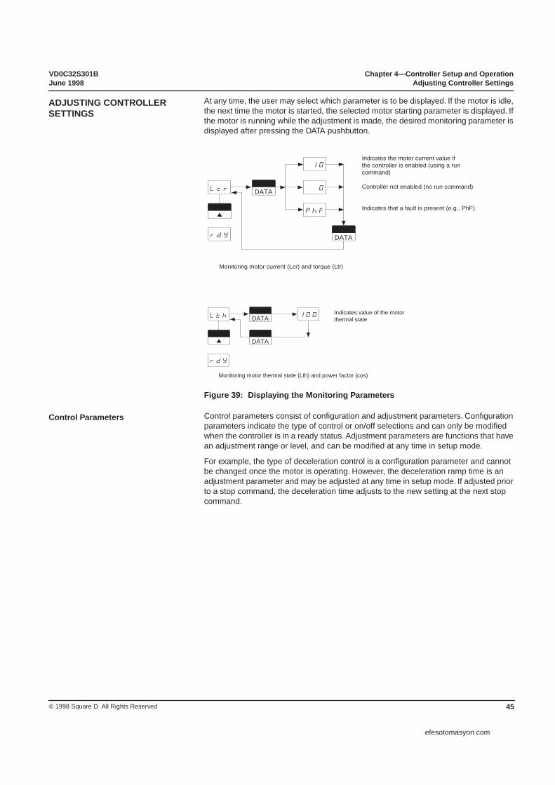
VD0C32S301B Chapter 4—Controller Setup and OperationJune 1998 Adjusting Controller Settings
45© 1998 Square D All Rights Reserved
At any time, the user may select which parameter is to be displayed. If the motor is idle, the next time the motor is started, the selected motor starting parameter is displayed. If the motor is running while the adjustment is made, the desired monitoring parameter is displayed after pressing the DATA pushbutton.
Figure 39: Displaying the Monitoring Parameters
Control parameters consist of configuration and adjustment parameters. Configuration parameters indicate the type of control or on/off selections and can only be modified when the controller is in a ready status. Adjustment parameters are functions that have an adjustment range or level, and can be modified at any time in setup mode.
For example, the type of deceleration control is a configuration parameter and cannot be changed once the motor is operating. However, the deceleration ramp time is an adjustment parameter and may be adjusted at any time in setup mode. If adjusted prior to a stop command, the deceleration time adjusts to the new setting at the next stop command.
ADJUSTING CONTROLLER SETTINGS
DATA
DATA
Lcr
10
0
PhF
rdY
Indicates the motor current value ifthe controller is enabled (using a runcommand)
Controller not enabled (no run command)
Indicates that a fault is present (e.g., PhF).
Monitoring motor current (Lcr) and torque (Ltr)
DATA
DATA
Lth 100
rdY
Indicates value of the motorthermal state
Monitoring motor thermal state (Lth) and power factor (cos)
Control Parameters
efesotomasyon.com

Chapter 4—Controller Setup and Operation VD0C32S301BAdjusting Controller Settings June 1998
© 1998 Square D All Rights Reserved46
Figure 40: Displaying the Control Parameters While in Lockout Mode
Figure 41: Displaying/Modifying the Control Parameters While in Setup Mode
DATA
21
ON
rdY
rdY
nLP
In
In
ILt
17.4DATA
Controller ready;default pointer position
or
When control power is applied,
if line power is not present,
indicates controller is ready;
nLP indicates controller is ready.
Lockout mode
Switch on the back of the keypad
Note: In lockout mode, parameters can be displayed but not modified.
DATA
PROG
DATA
DATA
ILt
10
20
30
Acc
StY
Acc
30
21
ON
21
ON
21
ON
PROG
PROG
Setup mode
Lev 1
Lev 2
Lev 3
Search forparameterto modify
Modificationof setting orconfiguration
Indicator lamp onsetup mode
Indicator lamp flashingAwaiting validation (PROG button) or cancellation (DATA button) of modification of the parameter value
rdY nLPController ready;default pointer position
or
efesotomasyon.com
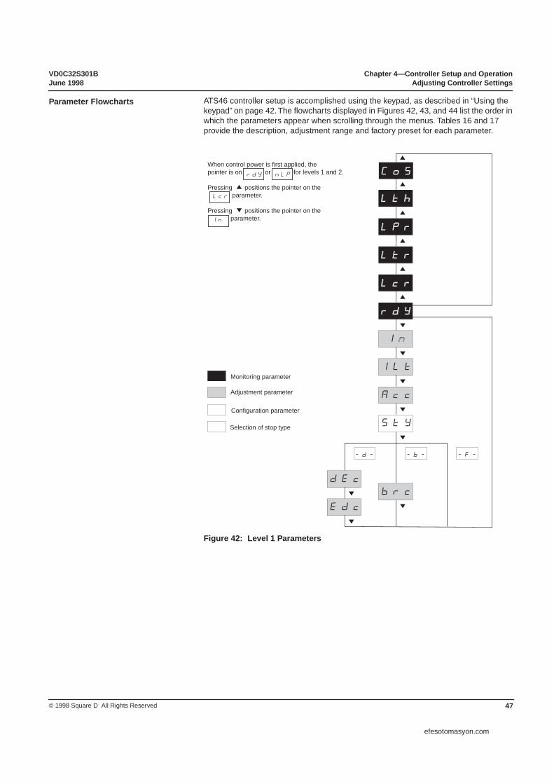
VD0C32S301B Chapter 4—Controller Setup and OperationJune 1998 Adjusting Controller Settings
47© 1998 Square D All Rights Reserved
ATS46 controller setup is accomplished using the keypad, as described in “Using the keypad” on page 42. The flowcharts displayed in Figures 42, 43, and 44 list the order in which the parameters appear when scrolling through the menus. Tables 16 and 17 provide the description, adjustment range and factory preset for each parameter.
Figure 42: Level 1 Parameters
Parameter Flowcharts
CoS
Lth
Ltr
Lpr
Lcr
rdY
StY
dEc
ILt
Acc
-b--d- -F-
Edc
brc
When control power is first applied, thepointer is on or for levels 1 and 2.
Pressing positions the pointer on the parameter.
Pressing positions the pointer on the parameter.
Monitoring parameter
Adjustment parameter
Configuration parameter
Selection of stop type
rdY nLP
In
Lcr
In
efesotomasyon.com
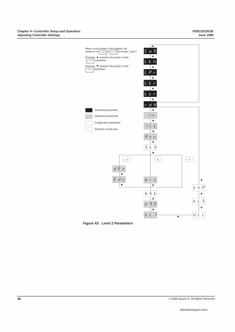
Chapter 4—Controller Setup and Operation VD0C32S301BAdjusting Controller Settings June 1998
© 1998 Square D All Rights Reserved48
Figure 43: Level 2 Parameters
-b--d- -F-
rdY
StY
dEc
bSt
ULL
tLS
ILt
Acc
brcEdc
tq0
tLI
thP
Monitoring parameter
Adjustment parameter
Configuration parameter
Selection of stop type
In
CoS
Lth
Ltr
Lpr
Lcr
When control power is first applied, thepointer is on or for levels 1 and 2.
Pressing positions the pointer on the parameter.
Pressing positions the pointer on the parameter.
rdY nLP
In
Lcr
rdY
efesotomasyon.com
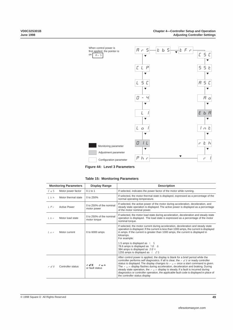
VD0C32S301B Chapter 4—Controller Setup and OperationJune 1998 Adjusting Controller Settings
49© 1998 Square D All Rights Reserved
Figure 44: Level 3 Parameters
Table 15: Monitoring Parameters
Monitoring Parameters Display Range DescriptionCoS Motor power factor 0.1 to 1 If selected, indicates the power factor of the motor while running.
Lth Motor thermal state 0 to 250% If selected, the motor thermal state is displayed, expressed as a percentage of the normal operating temperature.
LPr Active Power 0 to 250% of the nominal motor power
If selected, the active power of the motor during acceleration, deceleration, and steady state operation is displayed. The active power is displayed as a percentage of the motor nominal power.
Ltr Motor load state 0 to 250% of the nominal motor torque
If selected, the motor load state during acceleration, deceleration and steady state operation is displayed. The load state is expressed as a percentage of the motor nominal torque.
Lcr Motor current 0 to 6000 amps
If selected, the motor current during acceleration, deceleration and steady state operation is displayed. If the current is less than 1000 amps, the current is displayed in amps. If the current is greater than 1000 amps, the current is displayed in kiloamps. For example:
1.5 amps is displayed as 1.578.6 amps is displayed as 78.6384 amps is displayed as 3841255 amps is displayed as 1.25
rdY Controller status rrrrddddYYYY, rrrruuuunnnn or fault status
After control power is applied, the display is blank for a brief period while the controller performs self diagnostics. If all is clear, the rdY or ready controller status is displayed. The display changes to run once a start command is given. The run display flashes during acceleration, deceleration and braking. During steady state operation, the run display is steady. If a fault is incurred during diagnostics or controller operation, the applicable fault code is displayed in place of the controller status display
Or1
rth
Phr
IntLo1
OLI
OAo0-4
ASCLSC
SStCLp
ArS tbS tFr
EbA
OIL
CSC
When control power isfirst applied, the pointer ison
Monitoring parameter
Adjustment parameter
Configuration parameter
ArS
efesotomasyon.com

Chapter 4—Controller Setup and Operation VD0C32S301BAdjusting Controller Settings June 1998
© 1998 Square D All Rights Reserved50
Table 16: Level 1 and 2 Parameters
Parameter Type Display Range Preset Description
InNominal motor current(Level 1 or 2) C 50 to 130% of the controller
rated current
SeeTable 20 onpage 65.
The nominal motor current is factory set according to the controller rating and position of the switch beneath the keypad. If the factory setting is not between 95 and 105% of the motor FLA rating, adjust the In to obtain optimal performance and thermal protection. See “Setting the Motor Current” on page 52.
ILtCurrent Limit(Level 1 or 2) A 150 to 700% In -
max 500% ICL300
Sets the maximum current drawn during acceleration. See “Setting the Current Limit” on page 53.
Acc
Acceleration torque ramp(Level 1 or 2)
A 1 to 60 seconds 10
Adjusts the acceleration torque ramp. Adjusting the Accsetting changes the slope of the torque reference, providing a more or less gradual start.
StYStop type(Level 1 or 2) C -F- -d- -b- -F-
Selects the stopping control method. Selecting-F-,-d- or -b- indicates freewheel, deceleration ramp or braking. In freewheel mode (-F-), all voltage is removed from the motor following a STOP command. The motor coasts to a stop with the deceleration time dictated by the inertia and resistive torque of the driven load.
dEc
Deceleration ramp time(Level 1 or 2)
A 1 to 60 seconds 10
If deceleration ramping (-d-) is selected, the user may adjust the ramp time and voltage at which the ramp ends. dEc is used to adjust the time to change from measured torque to zero torque.
Edc
Threshold for change to freewheel at end of deceleration(Level 1 or 2)
A 0 to 100% of the measured nominal motor torque 20
If deceleration ramping (-d-) is selected, the torque level at which the deceleration ramp ends may be adjusted. Once the torque reaches the threshold value, the controller changes to freewheel mode and the motor coasts to a stop. If the torque is below the threshold setting when a stop command is given, controlled deceleration is not activated and the controller changes to freewheel stop.
brcBraking torque level(Level 1 or 2) A 0 to 100% 50
If braking (-b-) is selected, adjusts the braking level used during InTele braking. Note that the duration of the braking application is dependent on the motor loading.
bStVoltage boost(Level 2 only) C 50 to 100% of the supply
voltage oFF
If torque is too low on starting due to dry friction, stiff mechanism or high inertia, the boost function provides increased torque to initiate motor shaft rotation. Voltage is applied for 5 mains cycles during boost.
tq0Initial torque on starting (Level 2 only) A 0 to 100% of measured
nominal motor torque 10
Adjusts the initial torque upon energization. The initial torque setting and the slope indicated by the Acc define the motor starting performance. The starting performance may be optimized by adjusting the initial torque setting without modifying the slope of the ramp.
tLI
Limitation of maximum torque(Level 2 only)
A 10 to 200 of measured nominal motor torque oFF
Limits the peak torque provided by the motor. Primarily used to limit acceleration of high inertia applications, the torque limit combines with the slope and initial torque settings to provide a customized torque profile.
ULL
Motor underload threshold(Level 2 only)
C 20 to 100 of measured nominal motor torque oFF
An underload threshold can be set to prevent damage to the driven machinery or process resulting from an underload condition (i.e., dry pump condition). The underload detection is only active during steady state operation.To prevent nuisance tripping, the underload condition must last for 4 seconds. If a short underload condition occurs and loading returns to a value 10% above the user-defined threshold, the underload detection is reset. Detection of continuous and brief underload conditions is shown in Figure 37 on page 43.
tLSMaximum start time(Level 2 only) C 10 to 999 seconds oFF
Compares the motor acceleration time to the time set using tLS. If the time is exceeded, the controller changes to a fault state of stF.
thP
Motor thermal protection (Level 2 only)
C oFF to 30 10
The thermal overload class can be adjusted to provide Class 2, 10, 10A, 15, 20, 25 or 30 overload protection as defined per IEC 947-4-2. The thermal overload protection may be turned off if external protection is provided. Refer to Figure 36 on page 42 and Figure 37 on page 43 for information about trip curves for motor starting.
Type Abbreviations: A=Adjustment; C=Configuration
efesotomasyon.com

VD0C32S301B Chapter 4—Controller Setup and OperationJune 1998 Adjusting Controller Settings
51© 1998 Square D All Rights Reserved
Table 17: Level 3 Parameters
Parameter Type Adjustment Range Preset Description
ArS Automatic reset C oFF-on oFFRefer to Table 18 on page 57 for automatic reset operation.
CLP Torque control C oFF-on on
Torque control should be turned off for applications using motors connected in parallel on the same controller or a motor whose power is very low in relation to the rating of the controller.
LSc Stator loss compensation C 20 to 90% 50LSc optimizes the precision of the starting torque for constant torque applications.
0-4 Configuration of AO1 C 020-420 020Analog output AO1 can be configured to0 - 20 mA or 4 - 20 mA.
LI Assignment of LI C
oFF-LIA
LIE-LIH-LIL
LIC-LII-LIt
LIr
LIA
The following settings are available for assigning logic input LI:OFF = not assignedLIA= freewheel stopLIE = external faultLIH = reservedLIL = local controlLIC = control of cascading motorsLII = reservedLIt = motor overload resetLIr = fault reset
LoI Assignment of LO1 C oFF-tAI nnl tAI
The following settings are available for assigning logic output LO1:tAI = motor thermal alarmrnI = motor powered
OIL Current trip threshold A 50 to 300% of In oFF
This alarm is only active during steady state operation. An overcurrent condition, in relation to the threshold that has been set, must last 10 seconds to activate alarm LO2.
If a short overcurrent condition occurs and the current returns to a value 10% below the user-defined threshold, the overcurrent detection is reset. Detection of continuous and brief overcurrent conditions is shown in Figure 36 on page 42.
PhrDetection of phase rotation C oFF-123 321 oFF
Checks the direction of phase rotation in the mains supply. If the supply does not correspond to the selection, the controller changes to fault state PIF. This function is only activated if a run request is issued.
rI Assignment of relay R1 C rIF-rIL rIF
The following settings are available for assigning relay R1:rIF = fault relayrII = isolation relay (controls a line contactor)
rthReset of motor thermal state C no-YES no
After a request to reset the motor thermal state, parameter rth returns to no. Using this parameter should be limited to maintenance operations (changing motor, starter, etc.).
Int Return to factory setting C no-YES no
The int parameter automatically returns to the factory setting. After a request to return to factory settings, int returns to no.
EbAAdjustment of braking time C 0 to 100% 20
If braking (-b-) is selected, adjusts the motor stop time after the impulse braking phase.
AoAssignment of analog output AO1 C oFF Acr
Atr-Ath-ACOAcr
The following settings are available for assigning analog output AO1:OFF = not assignedAcr = motor currentAtr = motor torqueAth = motor thermal stateACO = power factorOutput can be configured to 0 - 20 mA or 4 - 20 mA using the parameter 0 - 4 and can be scaled using ASc.
AScScaling of analog output A01 C 50-500 200
Adjusts from 50 to 500% of the selected value; 20 mA corresponds to full scale.
efesotomasyon.com

Chapter 4—Controller Setup and Operation VD0C32S301BAdjusting Controller Settings June 1998
© 1998 Square D All Rights Reserved52
SSt Test on low power motor C on-oFF oFF
Checks the controller in a test or maintenance environment without having to use a motor with a motor power rating equivalent to that of the controller (esp. high powered controllers). Torque control (CLP) is automatically disabled when using SSt.
CSC Cascade operation C on-oFF OFF
Signals the operation of cascading motors. TCS ramp is inactive in this mode because the motor power does not match the controller rating.
tFr Elapsed time C on-oFF OFF
Indicates the operating time, in hours, since the last reset. Elapsed time includes starting, running and stopping time. May only be reset using one of the line communication options: VW3G46104 PC software or VW3G46301 PLC communication.
tbS Time before starting C 0-999 2
The time after a STOP command in freewheel mode or after the end of ramp or braking before a new START command will be accepted.
Type Abbreviations: A=Adjustment; C=Configuration
Table 17: Level 3 Parameters (Continued)
Parameter Type Adjustment Range Preset Description
The motor nominal current (In) is factory preset to the values listed in Table 16 on page 50. If the preset value is not within 95-105% of the motor nameplate current, or if using a 1.0 service factor motor, the In parameter should be adjusted as follows:
For 1.15 or 1.25 service factor motors, the nominal current may be set as high as 104% of the nameplate current if required to prevent nuisance tripping.
Service Factor Setting1.0 In = 0.96 x Nameplate Current
1.15 or 1.25 In = 1.00 x Nameplate Current
Setting the Motor Current
MOTOR OVERHEATINGMotor current draw above nameplate rating will result in motor temperature rise. Extended exposure to overcurrents will cause the motor to overheat resulting in thermal overload fault or equipment damage.The following conditions can cause excessive heating:• Excessive duty cycle (more than 6 evenly spaced starts per hour)• Excessive acceleration ramp due to high inertia loads• High ambient temperatureCheck with the motor manufacturer for the motor’s suitability for operation on a solid-state reduced voltage controller configured for your application.
• Motor thermal sensors built into the motor windings and connected through the control logic may be required for motor protection.
• Specific application duty motors, such as explosion proof and submersible motors will require enhanced protection and special considerations in application. The motor manufacturer MUST be consulted when applying these motors.
Failure to follow this instruction can result in injury or equipment damage.
CAUTION
efesotomasyon.com
VD0C32S301B Chapter 4—Controller Setup and OperationJune 1998 Adjusting Controller Settings
53© 1998 Square D All Rights Reserved
The current limit is expressed as a percentage of the In setting and is adjustable from 150 to 700%. However, the maximum starting current is limited to 500% of the controller rated current. The peak amperage drawn using the current limit feature can be determined by the following formula:
Ilt * (In / ICL) ≤ 500
For example, if the motor FLA equals the controller rated amps, the maximum current limit setting would be 500. If using a motor rated for 50% of the controller rating (the minimum setting), the current limit may be set as high as 700%.
For constant torque or high performance applications, the performance of the ALTISTART 46 controller may be optimized by the following steps:
1. Measure load requirements:
a. Set controller to monitor load torque (LTR).b. Start the motor with the factory default settings.c. Load the motor to the maximum continuous load torque for the application.d. Read the measured torque (LTR) for continuous duty (normal speed).e. Stop the motor.
2. Adjust the controller:
a. Set the current limit (ILT) to the maximum setting to provide the maximum starting torque.
b. Set the initial torque (tq0) and torque limit (tLI) to 120% of the measured load requirements. For example, if LTR = 50, set tq0 and tLI to 60.
3. Optimize the application:
a. Issue a run command. If the motor starts, reduce the stator loss compensation (LSC) by 10. Repeat until the motor no longer starts then increase by 10. The application is then optimized to within 10%.
b. If the motor does not start, increase the stator loss compensation (LSC) by 10. Repeat until the motor starts. The application is then optimized to within 10%.
Setting the Current Limit
Advanced Acceleration Ramp Adjustments
efesotomasyon.com

Chapter 4—Controller Setup and Operation VD0C32S301BAdjusting Controller Settings June 1998
© 1998 Square D All Rights Reserved54
efesotomasyon.com

VD0C32S301B Chapter 5—Fault ManagementJune 1998
55© 1998 Square D All Rights Reserved
INTRODUCTION . . . . . . . . . . . . . . . . . . . . . . . . . . . . . . . . . . . . . . . . . . . . . . . . . . . .54Fault Relay Setup . . . . . . . . . . . . . . . . . . . . . . . . . . . . . . . . . . . . . . . . . . . . . . . . .54Fault Display . . . . . . . . . . . . . . . . . . . . . . . . . . . . . . . . . . . . . . . . . . . . . . . . . . . . .54
RESETTING THE CONTROLLER . . . . . . . . . . . . . . . . . . . . . . . . . . . . . . . . . . . . . . .54Fault Definitions. . . . . . . . . . . . . . . . . . . . . . . . . . . . . . . . . . . . . . . . . . . . . . . . . . .55
TROUBLESHOOTING FAULTS . . . . . . . . . . . . . . . . . . . . . . . . . . . . . . . . . . . . . . . . .56Phase Fault . . . . . . . . . . . . . . . . . . . . . . . . . . . . . . . . . . . . . . . . . . . . . . . . . . . . . .56Frequency Fault . . . . . . . . . . . . . . . . . . . . . . . . . . . . . . . . . . . . . . . . . . . . . . . . . .56Supply Fault with Run Command Present . . . . . . . . . . . . . . . . . . . . . . . . . . . . . .57Motor Thermal Fault . . . . . . . . . . . . . . . . . . . . . . . . . . . . . . . . . . . . . . . . . . . . . . .57Starter Thermal Fault . . . . . . . . . . . . . . . . . . . . . . . . . . . . . . . . . . . . . . . . . . . . . .57Locked Rotor Fault . . . . . . . . . . . . . . . . . . . . . . . . . . . . . . . . . . . . . . . . . . . . . . . .57Motor Underload Fault. . . . . . . . . . . . . . . . . . . . . . . . . . . . . . . . . . . . . . . . . . . . . .58Max Starting Time Exceeded . . . . . . . . . . . . . . . . . . . . . . . . . . . . . . . . . . . . . . . .58External Fault . . . . . . . . . . . . . . . . . . . . . . . . . . . . . . . . . . . . . . . . . . . . . . . . . . . .58Internal Serial Link Fault . . . . . . . . . . . . . . . . . . . . . . . . . . . . . . . . . . . . . . . . . . . .58Overcurrent Fault . . . . . . . . . . . . . . . . . . . . . . . . . . . . . . . . . . . . . . . . . . . . . . . . .59Internal Failure Fault . . . . . . . . . . . . . . . . . . . . . . . . . . . . . . . . . . . . . . . . . . . . . . .59Phase Inversion Fault . . . . . . . . . . . . . . . . . . . . . . . . . . . . . . . . . . . . . . . . . . . . . .59
CHAPTER 5—FAULT MANAGEMENT
efesotomasyon.com

Chapter 5—Fault Management VD0C32S301BIntroduction June 1998
© 1998 Square D All Rights Reserved56
The ALTISTART 46 (ATS46) controller provides state-of-the-art protection for the motor and controller and provides flexibility and the ability to adapt to normal power disturbances. The following describes the diagnostics available on the ALTISTART 46 controller as well as how the controller will respond to the type of fault detected in manual and automatic restart modes. Finally, conditions which may have caused the fault condition and corrective actions for each fault code are given.
The ATS46 controller provides relay and logic output for fault indication. Both fault outputs can be configured to meet application requirements, which can then be set up to provide customized fault indication. The controller can also be set up for automatic restart. Refer to Chapter 3 for details on programming the controller.
Logic output LO1 is factory preset to indicate a motor thermal pre-alarm, which may be configured to initiate a correction in the process prior to exceeding the thermal capacity of the motor. The LO1 logic output may also be configured to signal that the motor is running.
Relay output R1 is configured by the user to provide detection of a fault only or control of an isolation contactor. A normally open and normally closed contact are provided to signal external devices. When in the factory default configuration, the R1 relay will energize following a successful self-diagnostic test and remain energized until a fault condition is detected. The R1 relay is in the de-energized state when control power is not applied and when a fault is detected.
If configured for control of an isolation contactor, the R1 relays stay in the de-energized state until a start command is issued. Following a start command the R1 relays remain energized until deceleration is complete or until a fault is detected. If controlled deceleration is not selected, the R1 relays change state following a stop command. This provides automatic interruption of the line voltage following a fault and when the motor is not in use.
If a fault occurs during the operation of the ALTISTART controller, a fault code is displayed on the keypad indicating the starter status. The last five faults that have occurred are stored in controller memory. To view the fault memory buffer, use the PC or PLC option. To view the controller settings while a fault code is displayed, press the DATA push-button until the programming menu is displayed. A red LED on the front of the controller also indicates a fault condition.
Fault conditions are broken into three categories: internal, phase, and thermal. To re-start the motor, the fault condition must be cleared and the controller must be reset. The method used to reset the controller depends on the type of fault detected and if automatic re-start is selected.
INTRODUCTION
HAZARDOUS VOLTAGERead and understand these procedures before servicing ATS46 controllers. Installation, adjustment, repair, and maintenance of these controllers must be performed by qualified personnel.
Electrical shock will result in death or serious injury.
DANGER
Fault Relay Setup
Fault Display
RESETTING THE CONTROLLER
efesotomasyon.com

VD0C32S301B Chapter 5—Fault ManagementJune 1998 Resetting the Controller
57© 1998 Square D All Rights Reserved
The ATS46 controller continuously monitors the motor and starter performance. If a fault is detected, the controller will interrupt motor operation and switch to a freewheel stop. After the fault has cleared, the steps required to restart the motor depend on the type of fault that was detected. The following is a guide for restarting following a fault condition:
Cycle Control Power: Cycling control power resets the controller following any fault condition and is required for non-resettable faults. A new or maintained run command will restart the motor after control power is recycled if the fault has cleared.
Manual Restart: The controller may be restarted by issuing a new run command after any resettable fault once the fault has cleared.
Auto Restart: If selected, the controller will restart automatically only if a maintained run command is preset, when using two wire control. An automatic restart will only occur after specific faults have cleared. Following a Type 1 fault, the controller will restart once the fault has cleared. Following a Type 2 fault, the controller will attempt to restart the motor after 60 seconds. If the fault has not cleared after 6 successive attempts, the fault must then be reset by cycling control power. A manual restart is required following a Type 3 fault.
Table 18: Fault DefinitionsTo Restart Motor
Code Description Refer to Page Cycle Control Power Manual Restart Auto Restart TypeOcF
InF
PiF
Overcurrent faultInternal failure faultPhase inversion fault
616161
X
PhF Phase fault 58X X 1
FrF Frequency fault 58
USF Supply fault 59 X X 2
OLF[1]
OhF
LrF
ULF
StF
EtF
SLF
Motor thermal faultStarter thermal faultLocked rotor faultMotor underloadMax start time exceededExternal faultSerial link fault
59595960606060
X 3
[1] If LI is configured for motor overload reset (Lit), operator acknowledgment of the overload condition is required. The overload must also be reset through the logic input after the fault has cleared before restarting the motor.
Fault Definitions
UNINTENDED EQUIPMENT ACTION• Automatic restart can only be used for machines or installations that present no
danger for personnel or equipment in the event of automatic restarting.• Equipment operation must conform with national and local safety regulations.Failure to follow this instruction can result in death or serious injury.
WARNING
efesotomasyon.com

Chapter 5—Fault Management VD0C32S301BTroubleshooting Faults June 1998
© 1998 Square D All Rights Reserved58
Resetting the controller once the fault has cleared may not correct the condition that caused the fault to occur. In addition, there are failure modes of this controller which may require an external device to ensure power is removed from the motor. Refer to Chapter 2 for proper installation guidelines.
The following guidelines provide general troubleshooting assistance based on the fault code displayed on the keypad. If the controller is still inoperative after checking the motor and system status as recommended, consult your local Square D sales office.
Fault Code: PhF
Possible Cause:
• Mains supply failure greater than 500 ms when run command is present.• Motor current draw less than 10% of the nominal starter rating.• SCR failure• Power factor greater than 95% lagging
Corrective Action:
• Verify that supply voltage is present on L1-L2-L3 terminals. If an isolation contactor is used, it must close within 200 ms of a run command.
• Check for open phases including:— Blown fuses— Open or loose power connections— SCR failure - not resettable via control logic
• If the fault is detected after completion of the acceleration ramp, ensure that the proper connection of the shorting contactor if used. The output of the shorting contactor must be connected to terminals A2-B2-C2, and must close within 200 msec after the motor is up to speed.
• Motor current draw must be more than 10% of the controller rating while running without a shorting contactor.
Fault Code: FrF
Possible Cause:
• Mains supply frequency outside acceptable limits.
Corrective Action:
Check that the frequency is between
• 60 Hz +/- 3.6 Hz (56.4 Hz to 63.6 Hz)• 50 Hz +/- 2.5 Hz (47.5 Hz to 52.5 Hz)
TROUBLESHOOTING FAULTS
MOTOR OVERHEATINGFailure of the controller solid-state switches can cause single-phase operation of the motor.• Use an isolation device consisting of either a circuit breaker equipped with a shunt
trip coil or an electromagnetic contactor to open the line side of the controller.• The isolation device must be capable of interrupting motor locked rotor current.• Connect the Fault relay of the ALTISTART controller to open the isolation device
in the event of a controller fault.Failure to follow this instruction can result in injury or equipment damage.
CAUTION
Phase Fault
Frequency Fault
efesotomasyon.com

VD0C32S301B Chapter 5—Fault ManagementJune 1998 Troubleshooting Faults
59© 1998 Square D All Rights Reserved
Fault Code: USF
Possible Cause:
• Voltage is not present at L1-L2-L3 terminals when a run command is present.
Corrective Action:
• Verify that supply voltage is present on L1-L2-L3 terminals. If an isolation contactor is used, it must close within 200 ms of a run command.
• Check for open phases including:
— Blown fuses— Open or loose power connections— SCR failure - not resettable via control logic
Fault Code: OLF
Possible Cause:
• Motor overload• Excessive starting or stopping time or frequency• Motor operating current incorrectly set
Corrective Action:
• Inspect motor and driven equipment for problems, including:
— locked shaft— mechanical overload
• Check the dynamics of the load and driven machine for suitability with reduced voltage starting.
• Check the duty cycle for the selected thermal overload class. • Check the In setting.
Fault Code: OhF
Possible Cause:
• Duty cycle above the thermal capabilities of the controller.• Ambient temperature too high. • Poor air circulation/lack of ventilation.
Corrective Action:
• Reduce duty cycle demand on controller.• Provide additional cooling around controller.• Reduce ambient temperature requirements.
Fault Code: LrF
Possible Cause:
• Current greater than 500% of the motor FLA setting is detected for more than 200 ms during steady state operation.
Corrective Action:
• Check motor for locked shaft. Remove obstruction prior to restarting.
Supply Fault with Run Command Present
Motor Thermal Fault
Starter Thermal Fault
Locked Rotor Fault
efesotomasyon.com

Chapter 5—Fault Management VD0C32S301BTroubleshooting Faults June 1998
© 1998 Square D All Rights Reserved60
Fault Code: ULF
Only applicable if ULL is programmed. ULL is factory pre-set to NO.
Possible Cause:
• Load level below the set ULL level.• Damage to drive train (broken belts, shafts, etc.).• Pump running dry or with no flow.
Corrective Action:
• Check the application for changes that may cause performance outside acceptable limits
— Change in process, loading, or operation— Mechanical system inspection— Incident in pump hydraulic circuit
Fault Code: StF
Only applicable if tLS is programmed. tLS is factory pre-set to NO.
Possible Cause:
• Start time exceeds tLS maximum start time setting.• Change in process, loading or operation.
Corrective Action:
• Check the application for changes that may cause performance outside acceptable limits
— Mechanism wear— Mechanical incident
Fault Code: EtF
Only applicable if LI is programmed to detect external fault LIE. LI is factory pre-set to NO.
Possible Cause:
• External fault detected and signaled to the logic input.
Corrective Action:
• Check external fault detection mechanism.
Fault Code: SLF
Possible Cause:
• Bad connection of the keypad or serial link option module.
Corrective Action:
• Check option module connection • Replace option module
Motor Underload Fault
Max Start Time Exceeded
External Fault
Internal Serial Link Fault
efesotomasyon.com

VD0C32S301B Chapter 5—Fault ManagementJune 1998 Troubleshooting Faults
61© 1998 Square D All Rights Reserved
Fault Code: OcF
Possible Cause:
• High impedance short circuit at the output of the controller• Internal short circuit• Improper sequence of shorting contactor
Corrective Action:
• Remove power from controller and check for:
— Damage to power cables and/or motor insulation— Damage to thyristors— Damage to shorting contactor/contactor stuck in closed position
Fault Code: InF
Possible Cause:
• Bad internal connection• Rating not recognized
Corrective Action:
• Remove power from controller and check the internal connections.
Fault Code: PiF
Only applicable if Phr is activated. Phr is factory pre-set to NO.
Possible Cause:
• Phase rotation of the mains does not match the Phr selection.
Corrective Action:
• Remove power from the motor and switch two phases of the mains supply.
Overcurrent Fault
Internal Failure Fault
Phase Inversion Fault
efesotomasyon.com

Chapter 5—Fault Management VD0C32S301BTroubleshooting Faults June 1998
© 1998 Square D All Rights Reserved62
efesotomasyon.com

VD0C32S301B Chapter 6—Servicing the ControllerJune 1998
63© 1998 Square D All Rights Reserved
INTRODUCTION . . . . . . . . . . . . . . . . . . . . . . . . . . . . . . . . . . . . . . . . . . . . . . . . . . . .62PERSONNEL PROTECTION PRECAUTIONS . . . . . . . . . . . . . . . . . . . . . . . . . . . . .62LIST OF TOOLS AND INSTRUMENTS . . . . . . . . . . . . . . . . . . . . . . . . . . . . . . . . . . .63STANDARDS . . . . . . . . . . . . . . . . . . . . . . . . . . . . . . . . . . . . . . . . . . . . . . . . . . . . . . .63PARTS REPLACEMENT . . . . . . . . . . . . . . . . . . . . . . . . . . . . . . . . . . . . . . . . . . . . . .64CONTROL MODULE REPLACEMENT . . . . . . . . . . . . . . . . . . . . . . . . . . . . . . . . . . .65POWER SECTION REPAIR . . . . . . . . . . . . . . . . . . . . . . . . . . . . . . . . . . . . . . . . . . . .66
ATS46D17 to C32 Controllers . . . . . . . . . . . . . . . . . . . . . . . . . . . . . . . . . . . . . . .66SCR Replacement . . . . . . . . . . . . . . . . . . . . . . . . . . . . . . . . . . . . . . . . . . . . . . . .67FIlter Card Replacement . . . . . . . . . . . . . . . . . . . . . . . . . . . . . . . . . . . . . . . . . . .69Thermal Switch and Fan Replacement . . . . . . . . . . . . . . . . . . . . . . . . . . . . . . . .69Control Power Transformer (CPT) Replacement . . . . . . . . . . . . . . . . . . . . . . . . .70
POWER SECTION REPAIR . . . . . . . . . . . . . . . . . . . . . . . . . . . . . . . . . . . . . . . . . . . .71ATS46C41N to M12 Controllers . . . . . . . . . . . . . . . . . . . . . . . . . . . . . . . . . . . . .71SCR Power Pole Assembly . . . . . . . . . . . . . . . . . . . . . . . . . . . . . . . . . . . . . . . . .71Firing Interface Board Replacement . . . . . . . . . . . . . . . . . . . . . . . . . . . . . . . . . . .72Current Measurement Board Replacement. . . . . . . . . . . . . . . . . . . . . . . . . . . . . .74Thermal Switch Replacement . . . . . . . . . . . . . . . . . . . . . . . . . . . . . . . . . . . . . . . .75Fan Replacement . . . . . . . . . . . . . . . . . . . . . . . . . . . . . . . . . . . . . . . . . . . . . . . . .75Control Power Transformer Replacement. . . . . . . . . . . . . . . . . . . . . . . . . . . . . . .75
CHAPTER 6—SERVICING THE CONTROLLER
efesotomasyon.com
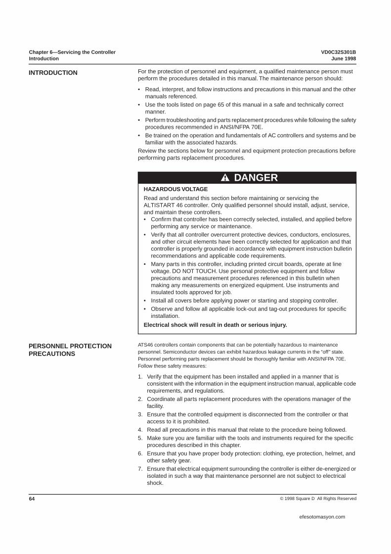
Chapter 6—Servicing the Controller VD0C32S301BIntroduction June 1998
© 1998 Square D All Rights Reserved64
For the protection of personnel and equipment, a qualified maintenance person must perform the procedures detailed in this manual. The maintenance person should:
• Read, interpret, and follow instructions and precautions in this manual and the other manuals referenced.
• Use the tools listed on page 65 of this manual in a safe and technically correct manner.
• Perform troubleshooting and parts replacement procedures while following the safety procedures recommended in ANSI/NFPA 70E.
• Be trained on the operation and fundamentals of AC controllers and systems and be familiar with the associated hazards.
Review the sections below for personnel and equipment protection precautions before performing parts replacement procedures.
ATS46 controllers contain components that can be potentially hazardous to maintenance personnel. Semiconductor devices can exhibit hazardous leakage currents in the “off” state. Personnel performing parts replacement should be thoroughly familiar with ANSI/NFPA 70E. Follow these safety measures:
1. Verify that the equipment has been installed and applied in a manner that is consistent with the information in the equipment instruction manual, applicable code requirements, and regulations.
2. Coordinate all parts replacement procedures with the operations manager of the facility.
3. Ensure that the controlled equipment is disconnected from the controller or that access to it is prohibited.
4. Read all precautions in this manual that relate to the procedure being followed. 5. Make sure you are familiar with the tools and instruments required for the specific
procedures described in this chapter. 6. Ensure that you have proper body protection: clothing, eye protection, helmet, and
other safety gear. 7. Ensure that electrical equipment surrounding the controller is either de-energized or
isolated in such a way that maintenance personnel are not subject to electrical shock.
INTRODUCTION
HAZARDOUS VOLTAGERead and understand this section before maintaining or servicing the ALTISTART 46 controller. Only qualified personnel should install, adjust, service, and maintain these controllers.• Confirm that controller has been correctly selected, installed, and applied before
performing any service or maintenance.• Verify that all controller overcurrent protective devices, conductors, enclosures,
and other circuit elements have been correctly selected for application and that controller is properly grounded in accordance with equipment instruction bulletin recommendations and applicable code requirements.
• Many parts in this controller, including printed circuit boards, operate at line voltage. DO NOT TOUCH. Use personal protective equipment and follow precautions and measurement procedures referenced in this bulletin when making any measurements on energized equipment. Use instruments and insulated tools approved for job.
• Install all covers before applying power or starting and stopping controller.• Observe and follow all applicable lock-out and tag-out procedures for specific
installation.Electrical shock will result in death or serious injury.
DANGER
PERSONNEL PROTECTION PRECAUTIONS
efesotomasyon.com

VD0C32S301B Chapter 6—Servicing the ControllerJune 1998 Standards
65© 1998 Square D All Rights Reserved
8. Ensure that all power sources feeding the controller are de-energized and locked/tagged out before opening the controller door or performing parts replacement procedures. Never assume the power is off. Always check for voltage with a properly rated voltage sensing device.
9. Inspect the controller bonding and ground system and ensure that the controller is properly grounded per the applicable codes and recommendations in this instruction bulletin.
ATS46 controllers use some specialized components to achieve rated performance during operation. Some of the components in the controller require special attention. For example, the SCRs require specific torque settings for proper operation. When replacing parts, follow the guidelines on page 2 and those listed throughout the book.
• Be sure to install thermal grease when mounting components which use the heatsink for dissipating heat (i.e., power semiconductor devices).
• Always torque semiconductor components using the method described in the applicable parts replacement procedure.
• If the controller is removed from its permanent mounting location while replacing parts, ensure that it is properly secured in an upright position before re-energizing.
• During maintenance, do not block, impede, or otherwise diminish cooling air flow over or through the controller.
• When installing a new control module, the controller may require programming if the factory default settings are not suitable for the specific application.
• Avoid touching exposed conductors and component leads with skin or clothing.
The tools and instruments required to perform maintenance and replace components on the ATS46 controller are listed below:
• Set of magnetized flat blade screw drivers• Set of magnetized phillips screw drivers• Set of Torx® screw drivers• 1/4” drive metric socket set, 5.5 to 14 mm• One 2’ (1/4” drive) socket extension• One 2’ (1/4” drive) socket extension• Metric hex key set, 2 to 14 mm• Regular hex key set, 1/4” to 9/16”• Metric ball-end hex key set, 2 to 14 mm• Torque wrench, 4.4 to 352 lb-in (0.5 to 40 N•m)• Metric hex key sockets for torque wrench• Metric drive sockets for torque wrench• Thermal grease (Alcoa #2EJC or equivalent)• Set of open/box end wrenches, 5.5 to 19 mm• Multimeter, 0-1000 V (Fluke 87 or equivalent)• Clamp-On Current Probe, 0-600 A (Fluke 80i-600A or equivalent)• Connector Extractor
This manual references the latest revision of the following standards:
• ANSI/NFPA 70B, Electrical Equipment Maintenance• ANSI/NFPA 70E, Electrical Safety Requirements for Employee Workplaces• NEMA ICS 1.1, Safety Guidelines for the Application, Installation, and Maintenance
of Solid State Control• NEMA ICS 1.3, Preventive Maintenance of Industrial Control and Systems
Equipment• NEMA ICS 2 - Annex A, Maintenance of Motor Controllers After a Fault Condition• OSHA 29 CFR Part 1910, Electrical Safety-Related Work Practices
LIST OF TOOLS AND INSTRUMENTS
STANDARDS
efesotomasyon.com
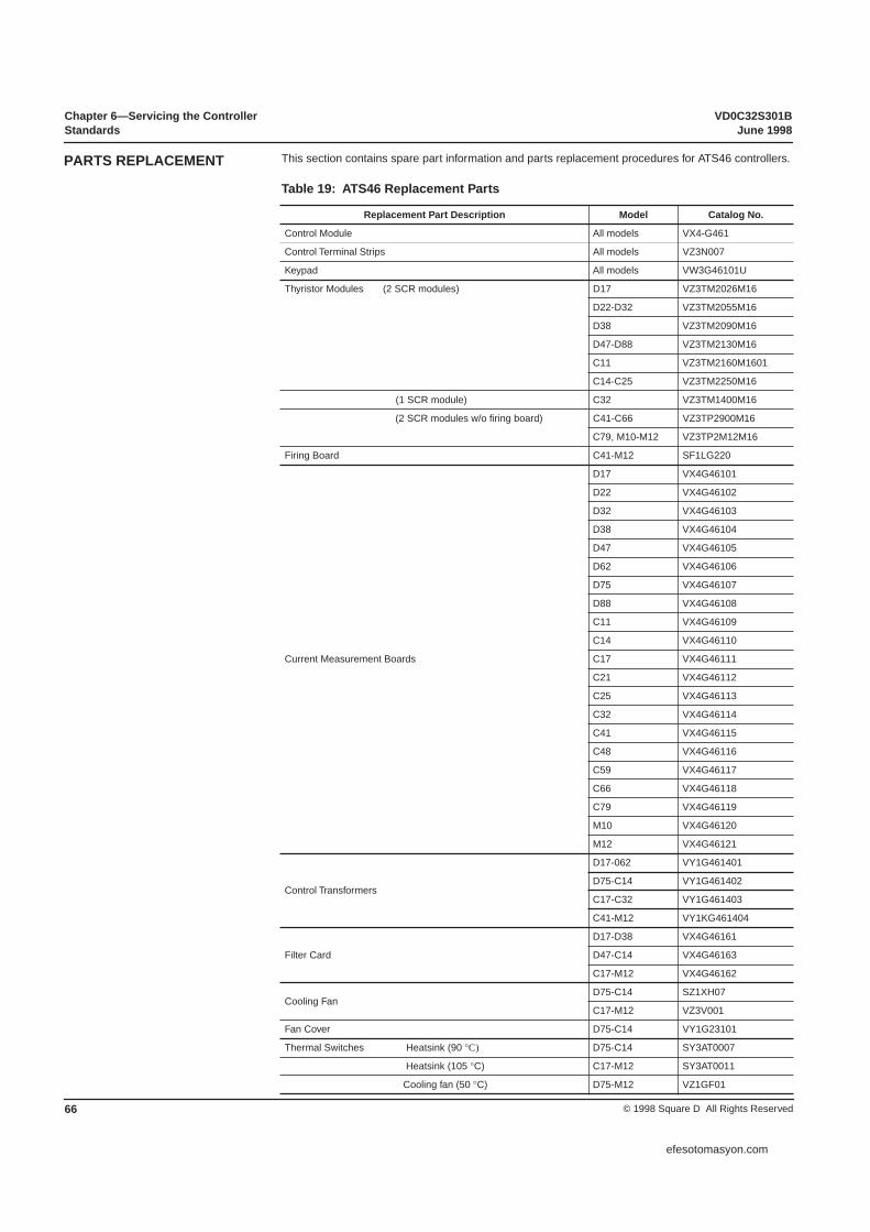
Chapter 6—Servicing the Controller VD0C32S301BStandards June 1998
© 1998 Square D All Rights Reserved66
This section contains spare part information and parts replacement procedures for ATS46 controllers.
Table 19: ATS46 Replacement Parts
Replacement Part Description Model Catalog No.
Control Module All models VX4-G461
Control Terminal Strips All models VZ3N007
Keypad All models VW3G46101U
Thyristor Modules (2 SCR modules) D17 VZ3TM2026M16
D22-D32 VZ3TM2055M16
D38 VZ3TM2090M16
D47-D88 VZ3TM2130M16
C11 VZ3TM2160M1601
C14-C25 VZ3TM2250M16
(1 SCR module) C32 VZ3TM1400M16
(2 SCR modules w/o firing board) C41-C66 VZ3TP2900M16
C79, M10-M12 VZ3TP2M12M16
Firing Board C41-M12 SF1LG220
Current Measurement Boards
D17 VX4G46101
D22 VX4G46102
D32 VX4G46103
D38 VX4G46104
D47 VX4G46105
D62 VX4G46106
D75 VX4G46107
D88 VX4G46108
C11 VX4G46109
C14 VX4G46110
C17 VX4G46111
C21 VX4G46112
C25 VX4G46113
C32 VX4G46114
C41 VX4G46115
C48 VX4G46116
C59 VX4G46117
C66 VX4G46118
C79 VX4G46119
M10 VX4G46120
M12 VX4G46121
Control Transformers
D17-062 VY1G461401
D75-C14 VY1G461402
C17-C32 VY1G461403
C41-M12 VY1KG461404
Filter Card
D17-D38 VX4G46161
D47-C14 VX4G46163
C17-M12 VX4G46162
Cooling FanD75-C14 SZ1XH07
C17-M12 VZ3V001
Fan Cover D75-C14 VY1G23101
Thermal Switches Heatsink (90 °C) D75-C14 SY3AT0007
Heatsink (105 °C) C17-M12 SY3AT0011
Cooling fan (50 °C) D75-M12 VZ1GF01
PARTS REPLACEMENT
efesotomasyon.com

VD0C32S301B Chapter 6—Servicing the ControllerJune 1998 Replacing the Control Module
67© 1998 Square D All Rights Reserved
ATS46 controllers use metric fasteners and require the use of metric driver tools. Do not substitute SAE or any alternate fastener. Substitution may result in damage to threaded inserts, breakage of components and subassemblies, overheated electrical connections due to improper torque levels, and general structural failure.
All procedures in this section must be performed with power removed from the controller.
To gain access to the power section or for replacement on all ATS46 models, remove the control module.
To remove the control module, follow these steps:
1. Using a flat blade or Torx screw driver, remove the four screws from the front of the control module.
2. Using a connector extractor, disconnect the nine electrical connectors from the back of the module. While the connectors and module are labeled, note the label and location of each connector. Figure 45 shows a diagram of the module and its connector labels.
Figure 45: Replacing the Control Module
To replace the control module, follow these steps:
1. Install the electrical connections. Push all connectors so that they are firmly in place.2. Mount the control module to the power section. Carefully secure all wires in the
controller to prevent damage to the wire or loosening of the connections.3. Retighten the four holding screws.
NOTES: When the control module is damaged, the entire module must be replaced. Any attempt to access, repair, or inspect the control module’s circuit boards voids the product warranty.
When replacing the control module, note that the replacement control module does not include the operator interface (keypad or communications module). The user must purchase a replacement operator interface separately.
EQUIPMENT DAMAGE• ALTISTART 46 controllers use metric fasteners.• Do not substitute SAE or alternate fasteners.Failure to follow this instruction can result in equipment damage.
CAUTION
CONTROL MODULE REPLACEMENT
purpleblackred
bluewhite
redJ*1 J*2
Typical Connection to SCRs
Back of Module
J3J4
J5
J31J32 J21J22 J11J12
Front of Module
Keypadprovided
separately
efesotomasyon.com

Chapter 6—Servicing the Controller VD0C32S301BReplacing the Control Module June 1998
© 1998 Square D All Rights Reserved68
The control module must be removed to repair the components in the power section. The ATS 46 product line consists of five frame sizes which share common power section design. The replacement process for the power components is similar for units within a frame size. For units rated 17 through 320 amps, remove the control module and protective housing to access the power components directly.
These items are replaceable in the power section of the 17 through 320 A models (D17 to C32):
• SCRs• Current measurement board• Filter card• Control power transformer• Fan and thermal switches (on models rated 72 A and above)Figures 46, 47, and 48 show available replacement parts. Table 19 on page 66 lists catalog numbers.
Figure 46: ATS46D17, D22, D32, and D38 Controllers
Figure 47: ATS46D47, D62, D75, D88, C11, and C14 Controllers
POWER SECTION REPAIR ATS46D17 TO C32 CONTROLLERS
Control PowerTransformer
SCRs
Current MeasurementBoard
Filter Card
Plastic Cover (bottom)
Plastic Cover (top)
Side Panel
Control PowerTransformer
Fan ThermalSwitch
Filter Card
Front Cover Screws
Fan Control Switch
SCRs
CurrentMeasurement
Board
Plastic Cover (top)
Plastic Cover (bottom)
Heatsink Thermal
Switch
efesotomasyon.com

VD0C32S301B Chapter 6—Servicing the ControllerJune 1998 Replacing the Control Module
69© 1998 Square D All Rights Reserved
Figure 48: ATS46C17, C21, C25, and C32 Controllers
When an SCR fails, the ATS46 controller will not attempt to start the motor. Upon a start command, a device with a failed SCR immediately shows a phase fault or internal fault code.
To verify the damaged pole and determine how many poles should be replaced, perform the following tests. For D17 through C32 controllers, the SCR modules can be directly accessed.
NOTE: The ATS46C32N controllers use two SCRs per phase. All other models use a dual pack SCR that requires one module per phase. 1. With the equipment switched off, isolate the starter by disconnecting the power
terminals. 2. Remove line power from controller. Using a continuity meter, check the thyristors in
pairs. Figure 49 illustrates this process, phase by phase, between terminals 1L1-2T1, 3L2-4T2, 5L3-6T3. If continuity is indicated, at least one of the thyristors is short-circuited.
Figure 49: Checking Thyristors
Control PowerTransformer
Fan Assembly Fan House Screws
SCRs [1]
CurrentMeasurement
Board
Fan Thermal Switch
Heatsink Thermal Switch
FilterCards
[1] Two per phase for ATS46C32. One per phase for ATS46C17 to C25.
SCR Replacement
HAZARDOUS VOLTAGEBefore checking thyristors:• Disconnect all power.• Place a “DO NOT TURN ON” label on the controller disconnect.• Lock disconnect in open position.Electrical shock will result in death or serious injury.
DANGER
+- + -
Open - SCR not failedClosed - SCR failed
L LT T
efesotomasyon.com
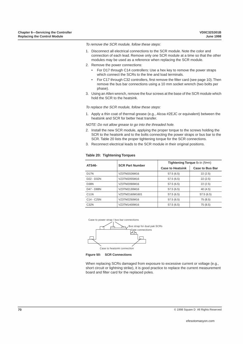
Chapter 6—Servicing the Controller VD0C32S301BReplacing the Control Module June 1998
© 1998 Square D All Rights Reserved70
To remove the SCR module, follow these steps:
1. Disconnect all electrical connections to the SCR module. Note the color and connection of each lead. Remove only one SCR module at a time so that the other modules may be used as a reference when replacing the SCR module.
2. Remove the power connections:• For D17 through C14 controllers: Use a hex key to remove the power straps
which connect the SCRs to the line and load terminals. • For C17 through C32 controllers, first remove the filter card (see page 10). Then
remove the bus bar connections using a 10 mm socket wrench (two bolts per phase).
3. Using an Allen wrench, remove the four screws at the base of the SCR module which hold the SCR to the heatsink.
To replace the SCR module, follow these steps:
1. Apply a thin coat of thermal grease (e.g., Alcoa #2EJC or equivalent) between the heatsink and SCR for better heat transfer.
NOTE: Do not allow grease to go into the threaded hole.2. Install the new SCR module, applying the proper torque to the screws holding the
SCR to the heatsink and to the bolts connecting the power straps or bus bar to the SCR. Table 20 lists the proper tightening torque for the SCR connections.
3. Reconnect electrical leads to the SCR module in their original positions.
Figure 50: SCR Connections
When replacing SCRs damaged from exposure to excessive current or voltage (e.g., short circuit or lightning strike), it is good practice to replace the current measurement board and filter card for the replaced poles.
Table 20: Tightening Torques
ATS46- SCR Part NumberTightening Torque lb-in (N•m)
Case to Heatsink Case to Bus Bar D17N VZ3TM2026M16 57.5 (6.5) 22 (2.5)
D22 - D32N VZ3TM2055M16 57.5 (6.5) 22 (2.5)
D38N VZ3TM2090M16 57.5 (6.5) 22 (2.5)
D47 - D88N VZ3TM2130M16 57.5 (6.5) 40 (4.5)
C11N VZ3TM2160M1601 57.5 (6.5) 57.5 (6.5)
C14 - C25N VZ3TM2250M16 57.5 (6.5) 75 (8.5)
C32N VZ3TM1400M16 57.5 (6.5) 75 (8.5)
Case to power strap / bus bar connections
Case to heatsink connection
Bus strap for dual pak SCRsGate connections
efesotomasyon.com

VD0C32S301B Chapter 6—Servicing the ControllerJune 1998 Replacing the Control Module
71© 1998 Square D All Rights Reserved
For D17 through C14 controllers, there is one filter card per unit mounted below the L1/L2/L3 connections. For C17 through C32 controllers, there are three filter cards—one mounted to the bus bar on each phase.
To replace the filter card on D47 through C14 controllers, follow these steps:1. Disconnect electrical connections from the board. Note the position and color of
each wire for reassembly.2. Disconnect power straps to SCRs as needed to access filter card. 3. Using a flat blade screwdriver, remove the filter card mounting screws.
• Removing the bus wiring may facilitate the removal of the filter card. • To access the filter card (in D47 through C14 controllers only), follow these steps:
1. Take out the top two front cover screws. See Figure 47 on page 68.2. Take out the four screws from the bottom cover of the controller.3. Disconnect T1, T2, and T3 from SCR.4. Pull the bottom plastic end cap out.5. Slide side panels down.
6. Remove the filter card.7. Use a magnetic screwdriver to reinsert screws. To reinstall the filter card, reverse
steps 1 to 5. Retighten the housing screws and power connections.
To replace the filter card on C17 through C32 controllers, follow these steps:1. Remove electrical connections for the card to be replaced.2. Using a Torx screwdriver, remove the mounting screw.3. Remove the filter card.4. To reinstall a new filter card, reverse steps 1 through 3.
To remove the current measurement board:1. For D47 through C32 controllers, disconnect jumpers J13,J14, and J15 from the
current measurement board. See Figure 50 on page 70.2. Using a Torx screwdriver, loosen and remove the holding screws on the current
measurement board.3. On D17 through D38 controllers, the current transformers are mounted directly on
the current measurement board. To remove the board, the three bus wires from the SCRs have to be disconnected and pulled out from the current transformer.NOTE: To remove the bus wire from the current transformer, it may be necessary to remove the heat shrink from the terminal of the bus wire. Replace heat shrink upon re-installation.
4. Remove measurement board from power section; note connections for reassembly.
On ATS46D75 through C32N controllers, there are two thermal switches. One controls the operation of the cooling fan, and the other is an alarm for controller thermal protection. The output of the heatsink thermal switch is fed to the current measurement board. The output of the fan control is in series with the fan and control power transformer.
The cooling fans cycle on when the temperature of the heatsink exceeds 50 °C. If the cooling fan does not turn on and the temperature exceeds 50 °C, the thermal switch, the fan, or both may need to be replaced. The fans operate on 230 VAC single phase power. Use an external power supply, if desired, to test fan operation.
To replace a thermal switch, follow these steps:1. Disconnect the two electrical connections from the output of the switch.2. Using a Torx or flat blade screwdriver, remove the two holding screws. It may be
necessary to remove some of the SCR power connections to access the thermal switch.
3. Replace the thermal switch with the appropriate rated switch. The fan thermal switch should be rated for 50 °C, whereas the heatsink switch is rated for 95 °C or 105 °C, depending on the controller size.
FIlter Card Replacement
Thermal Switch and Fan Replacement
efesotomasyon.com

Chapter 6—Servicing the Controller VD0C32S301BReplacing the Control Module June 1998
© 1998 Square D All Rights Reserved72
To replace the fan on D75 through C14 controllers, follow these steps:
1. Turn the unit with the heatsink facing up (i.e., access the fan from the back of the unit).
2. Remove the two electrical connections.3. Remove the two holding screws.4. To install the replacement fan, reverse steps 1 through 3.
To replace the fan on C17 through C32 controllers, follow these steps:1. Remove the fan cover by removing the two cover screws. 2. Remove the six screws from the fan mounting plate.3. Disconnect the fan power supply wires from the control power transformer (White)
and from the thermal switch (Red). See Figure 51.4. Remove the fan assembly.5. To reinstall the replacement fan, reverse steps 1 through 4. Use caution when
installing the fan to prevent damage to the wires.
Figure 51: Fan Mounting Plate
The control power transformer (CPT) provides the power to the control module and fan (if supplied). To replace the CPT, the user must have access to the fan connections. Refer to “Thermal Switch and Fan Replacement” on page 71 to service the fan assembly.
To replace the CPT, follow these steps:
1. Disconnect the four colored transformer supply wires from the terminal block beneath the control power connections. See Figure 57 on page 76.
2. For D72 through C32 controllers, disconnect the two wires that supply the fan power. For C17 through C32 controllers, pull the fan power wires through the fan and controller housing one at a time.
3. Remove the four transformer mounting screws attaching the transformer to the power section base.
4. Remove the CPT.5. To install a replacement CPT, reverse steps 1 through 4. See Figure 57: Note the
proper connections.
Figure 52: Control Power Transformer Wiring
WhiteRedRed
White
Control Power Transformer (CPT) Replacement
C 230 400 460/500
White Green Blue Red
FromCPT
efesotomasyon.com

VD0C32S301B Chapter 6—Servicing the ControllerJune 1998 Replacing the Control Module
73© 1998 Square D All Rights Reserved
Some replacement parts on models ATS46C41 to M12N can only be accessed after removing other items in the power section. Make a record of the wire connections and the order and location of all components before removing them from the power section.
The following list contains replaceable items in the power section of the 410 through 1200 A models:
• Control module / Keypad• SCR power pole assemblies• Firing interface board• Current measurement board• Filter card• Control power transformer• Fan and thermal switches
Refer to Figure 53 to identify the available replacement parts. Table 19 on page 66 lists catalog numbers for each item. The instructions for replacing the control module, control power transformer, thermal switches, and fan are the same as for the ATS46C17 through C32N controllers described on pages 66 through 70.
Figure 53: ATS46C41, C48, C59, C66, C79, M10, M12
The SCR power pole assembly consists of the power pole, the firing interface board, and two thermal switches for ATS46C41 through M12N controllers. The power pole consists of two SCRs within a heatsink. The heatsink is tightened to provide balanced heat and current transfer within the assembly. The power pole, interface board, and thermal switches are available as individual parts. Pre-mounted thermal switches are provided with the replacement power pole.
NOTE: SCRs are not available for individual replacement. Replacement of a single SCR through disassembly of the power pole will void the product warranty.
The ATS46C41 through M12 controllers use a firing interface board. Each SCR pole requires one interface board. Replace the board if there is visible damage to any of the components following an SCR failure. The replacement power pole assembly does not include an interface board. Reuse the original interface board (unless it is damaged) or order a replacement interface board.
POWER SECTION REPAIR ATS46C41N TO M12 CONTROLLERS
Control PowerTransformer
Fan Assembly
Power Poles
CurrentMeasurementBoard
FilterBoard
FiringBoard
SCR Power Pole Assembly
efesotomasyon.com

Chapter 6—Servicing the Controller VD0C32S301BReplacing the Control Module June 1998
© 1998 Square D All Rights Reserved74
Refer to page 68 for SCR testing information. The ATS46C79 through M12 controllers use two SCR power poles connected in parallel. If an SCR in either pole is shorted, replace both poles in the SCR assembly.
To replace the SCR package, interface board, or thermal switches, remove the entire power pole assembly. Removal allows easier access to the individual components. Note the location of each wire as you remove the assembly. The interconnections between the SCR pole and firing interface board are not labeled.
To remove the power pole assembly from the controller chassis, follow these steps:
1. Remove the control module as described on page 67.2. Either rotate the control module mounting panel or remove it. Either action allows
access to the SCR poles, current measurement board, and control power transformer.
3. Disconnect the jumper to the interface card from the current measurement board. The label designation, from J4 to J9, depends on which pole the jumper connects to.
4. To remove the SCR pole assembly, disconnect the wires and remove the bolts indicated in Figure 54. Use a 10 mm wrench to remove the bolts.
5. Cut wire ties from the power pole assembly to the insulating wall.6. Pull the SCR pole assembly from the controller chassis using the handle on the
mounting bracket (C in Figure 54) and the free end of the lower braided cable.
Figure 54: SCR Power Pole Assembly
After removing the power pole assembly from the chassis, replace the SCR pole, interface board, or thermal switches.
To replace the firing interface board, follow these steps:
1. Label the wires connected to the interface board for easier identification when reassembling. Using a flat-head screwdriver, remove the seven screws holding red and white wires.
2. While holding interface board to pole assembly, remove two mounting screws and bolt on mounting bracket.
3. Reassemble pole by following step 2, then 1. Tighten the mounting bolts to 40 lb-in (4.5 N•m). In order for the controller to operate properly, the SCR firing circuits must be properly connected. Use Figure 55 on page 75 to identify the location of each wire.
bluewire
A
H
G
A
C
A Bolts (remove these)B Bolts (do not remove these)C Holding bracketD Interface boardE Shorting contactor connectionF Line connectionG Braided cablesH Fan switch connections
B
BD
E F
JX
9
red
red
black
black
1010191
A
AAA
Firing Interface Board Replacement
efesotomasyon.com

VD0C32S301B Chapter 6—Servicing the ControllerJune 1998 Replacing the Control Module
75© 1998 Square D All Rights Reserved
Figure 55: Interface Board Connections
To replace the power pole assembly on the controller chassis, follow these steps:
1. If replacing only the thermal switch or interface board, re-assemble the components to complete the power pole assembly. Complete this step before mounting the pole back in the controller chassis. Skip to step 3.
2. If replacing the SCR pole, remove the braided cables and standoffs. Use these in the new pole assembly. When replacing the braided cables, make sure cables are flush with the top side of the channel. Otherwise, proper conduction may not occur. Refer to Figure 56 for assembly of the cable to the channel.
3. Replace the red wire that is attached to the mounting bracket of the replacement pole. Re-tighten screw to maintain proper alignment of bracket.
4. Using the free end of the lower braided cable and the mounting bracket handle, replace the pole in the controller chassis.
5. Replace the removed wire from the pole assembly. Tighten the following to 80 lb-in (9 N•m): all 10 mm bolts holding the power pole assembly to the chassis; all connections to the bus bar.
6. Replace the jumper from the current measure board (see Figure 57 on page 76). Connect the four wires to the terminal block (see Figure 54 on page 74).
7. For C79 through M12 controllers: tighten to 40 N•m all bolts that connect the poles in parallel.
Figure 56: Assembly of Braided Cable to Heatsink
RED A
A to top of upper braided cableB to top mounting bracketC to bottom of upper braided cableD in black tubing from upper SCRE in white or yellow tubing from lower SCR
B
C
D
E
J
*
RED
RED
WHITE
RED
WHITE
RED
Heatsink
Bolt
Washer
BraidedCable
Washer
Nut
efesotomasyon.com
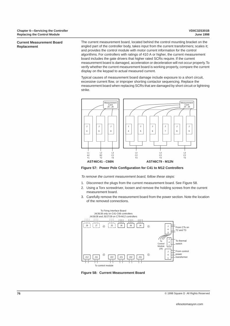
Chapter 6—Servicing the Controller VD0C32S301BReplacing the Control Module June 1998
© 1998 Square D All Rights Reserved76
The current measurement board, located behind the control mounting bracket on the angled part of the controller body, takes input from the current transformers; scales it; and provides the control module with motor current information for the control algorithms. For controllers with ratings of 410 A or higher, the current measurement board includes the gate drivers that higher rated SCRs require. If the current measurement board is damaged, acceleration or deceleration will not occur properly. To verify whether the current measurement board is working properly, compare the current display on the keypad to actual measured current.
Typical causes of measurement board damage include exposure to a short circuit, excessive current flow, or improper shorting contactor sequencing. Replace the measurement board when replacing SCRs that are damaged by short circuit or lightning strike.
Figure 57: Power Pole Configuration for C41 to M12 Controllers
To remove the current measurement board, follow these steps:
1. Disconnect the plugs from the current measurement board. See Figure 58.2. Using a Torx screwdriver, loosen and remove the holding screws from the current
measurement board.3. Carefully remove the measurement board from the power section. Note the location
of the removed connections.
Figure 58: Current Measurement Board
Current Measurement Board Replacement
J
4
J
6
J
8
MeasurementCard
J4 - J9
MeasurementCard
J4 - J9
AST46C79 - M12NAST46C41 - C66N
L1A2T1
L2B2T2
L3C2T3
J
4
J
5
J
7
L3C2T3
J
8
J
9
L3C2T3
L3C2T3
J
6
J9
To Firing Interface Board J4/J6/J8 only on C41-C66 controllers
J4/J6/J8 and J5/J7/J9 on C79-M12 controllers
To control module
From CTs on T2 and T3
To thermal switch
From control powertransformer
To ControlModule
(J5)
J7 J5 J43
J8 J6 J4
J12 J11 J22 J21 J32 J31
J41
J42
efesotomasyon.com

VD0C32S301B Chapter 6—Servicing the ControllerJune 1998 Replacing the Control Module
77© 1998 Square D All Rights Reserved
To replace the current measurement board, follow these steps:
1. Mount the board to the controller. Tighten the holding screws.2. Reconnect all jumpers to the measurement board.3. If plugs were removed, reconnect plugs on the end of the wires opposite the control
module and SCR poles.
NOTE: The power section of the ATS46C79 through M12 controllers uses two power sections connected in parallel. The replacement instructions are the same for the C79 to M12 controllers except for pole connections. Figure 53 on page 73 shows pole connections for the C41 through M12N.
The thermal switches from each pole are connected in series for operation of the fan and indication of heatsink over temperature. When replacing the thermal switch, note the location of the existing switch connection to the terminal block. This connection, on the pole assembly, is critical to proper operation of the fan and thermal alarm.
On the ATS46C41 through M12 controllers, there are thermal switches for fan control and detection of the heatsink temperature on each power pole assembly. The SCR power poles must be removed to gain access to the thermal switches.
Use the same fan replacement in the ATS46C41 through M12 controllers as for the ATS46C14 through C30 controllers. Refer to page 77 for fan replacement instructions. On C79 through M12 controllers, each fan operates independently, based on the left and right side temperature.
Control power transformer replacement for ATS46C41 through M12 controllers is the same as for ATS46C17 through C32 controllers. Refer to page 72 for CPT replacement instructions.
For additional assistance with replacing components or troubleshooting the ALTISTART controller, contact your local Square D Field Sales office, Square D Technical Services Department (800-634-2003), or the Square D Drives Product Support Group (919-217-6536).
Thermal Switch Replacement
Fan Replacement
Control Power Transformer Replacement
EQUIPMENT DAMAGE• After completing any repair of the ALTISTART controller, ensure that all power
connections are properly tightened and that the starter programming meets the application requirements.
• Do not substitute SAE or alternate fasteners.Failure to follow this instruction can result in injury or equipment damage.
CAUTION
efesotomasyon.com

Chapter 6—Servicing the Controller VD0C32S301BReplacing the Control Module June 1998
© 1998 Square D All Rights Reserved78
efesotomasyon.com

Table 20: Controller-Motor Combinations
ATS46 Model RatedCurrent
Standard Duty Applications Heavy Duty Applications
Motor Power Rating Motor Power Rating
ICL 208V 230V 460V 208V 230V 460VATS46D17N 17 3 5 10 2 3 7.5
ATS46D22N 22 5 7.5 15 3 5 10
ATS46D32N 32 7.5 10 20 5 7.5 15
ATS46D38N 38 10 - 25 7.5 10 20
ATS46D47N 47 - 15 30 10 - 25
ATS46D62N 62 15 20 40 - 15 30
ATS46D75N 75 20 25 50 15 20 40
ATS46D88N 88 25 30 60 20 25 50
ATS46C11N 110 30 40 75 25 30 60
ATS46C14N 145 40 50 100 30 40 75
ATS46C17N 176 50 60 125 40 50 100
ATS46C21N 210 60 75 150 50 60 125
ATS46C25N 257 75 100 200 60 75 150
ATS46C32N 320 100 125 250 75 100 200
ATS46C41N 410 125 150 300 100 125 250
ATS46C48N 480 150 - 350 125 150 300
ATS46C59N 590 - 200 400 150 - 350
ATS46C66N 660 200 250 500 - 200 400
ATS46C79N 790 250 300 600 200 250 500
ATS46M10N 1000 350 400 800 250 300 600
efesotomasyon.com

Merlin Gerin Square D Telemecanique
VD0C32S301B June 1998 Printed in USA© 1998 Square D All Rights Reserved
efesotomasyon.com