version 1, 2017 - catchments and creeks · 2017-09-06 · code of environmental practice –...
TRANSCRIPT

Version 1, 2017

© Catchments & Creeks Pty Ltd July, 2017 Page 2
Erosion & Sediment Control Field Guide for Pipeline Projects – Part 1
Version 1, July 2017 Prepared by: Grant Witheridge, Catchments and Creeks Pty Ltd
Published by: Catchments and Creeks Pty Ltd
Diagrams by: Grant Witheridge, Catchments and Creeks Pty Ltd
Photos by: Adam Pullen, Andrew Macleod (SEEC), Brisbane City Council, Catchments and Creeks Pty Ltd, Dirtbag, Geofabrics Aust. Hazell Bros., Project Rentals, The Integrated Group and Wet Earth Australia
Except as permitted under copyright laws, no part of this publication may be reproduced within another publication without the prior written permission of the publisher.
Permission, however, is granted for users to: · store the complete document on a database, but not isolated parts of the document · print all or part of the document, and distribute such printed material to a third party · distribute the complete document in electronic form to a third party, but not isolated parts of
the document. All diagrams are supplied courtesy of Catchments and Creeks Pty. Ltd. and remain the ownership of Catchments & Creeks Pty. Ltd. No diagram or photograph may be reproduced within another publication without the prior written permission of the Director of Catchments and Creeks Pty. Ltd. This document should be referenced as:
Witheridge 2017, Erosion & Sediment Control Field Guide for Pipeline Projects – Part 1. Catchments and Creeks Pty Ltd., Brisbane, Queensland Key words: erosion and sediment control, pipelines, pipeline installation, pipeline construction. Copies of this document may be downloaded from: www.catchmentsandcreeks.com.au © Catchments & Creeks Pty Ltd, 2017 Disclaimer Significant effort has been taken to ensure that this document is representative of current (2017) best practice erosion and sediment control practice; however, the author cannot and does not claim that the document is without error, or that the recommendations presented within this document will not be subject to future amendment as techniques and knowledge improve.
To be effective, erosion and sediment control measures must be investigated, planned, and designed in a manner appropriate for the given work activity and site conditions.
No warranty or guarantee, express, implied, or statutory is made as to the accuracy, reliability, suitability, or results of the methods or recommendations.
The author shall have no liability or responsibility to the user or any other person or entity with respect to any liability, loss, or damage caused, or alleged to be caused, directly or indirectly, by the adoption and use of any part of the document, including, but not limited to, any interruption of service, loss of business or anticipatory profits, or consequential damages resulting from the use of the document.
Specifically, adoption of the recommendations and procedures presented within this field guide will not guarantee: · compliance with any statutory obligations · compliance with specific water quality objectives · avoidance of environmental harm or nuisance.

© Catchments & Creeks Pty Ltd July, 2017 Page 3
Principal reference documents:
Best Practice Erosion & Sediment Control. International Erosion Control Association, (IECA) Australasia Chapter, 2008 Specifically, reference is made to:
Chapter 2 (Principles of ESC)
Chapter 4 (Design standards)
Chapter 6 (Site management)
Appendix C (Soils and revegetation)
Appendix I (Instream works)
Appendix K (Tracks and trails) IECA (2008) – Book 1
Code of Environmental Practice – Onshore pipelines, the Australian Pipelines Industry Association Ltd (APIA), May 2013
APIA Code of Environmental Practice
Pipeline Associated Watercourse Crossings, October 2005 Canadian Association of Petroleum Producers, Canadian Energy Pipeline Association and Canadian, Gas Association.
Prepared by TERA Environmental Consultants and Salmo Consulting Inc. Calgary, AB.
Canadian Pipeline Watercourse Crossings
Erosion & Sediment Control Field Guide for Pipeline Projects – Part 2, 2017
Witheridge 2017, Catchments and Creeks Pty Ltd., Brisbane, Queensland.
Download from:
www.catchmentsandcreeks.com.au
ESC Field Guide for Pipelines, Part-2

© Catchments & Creeks Pty Ltd July, 2017 Page 4
Contents Page Purpose of field guide 6 About the author 6 Introduction
Introduction 6 Impacts of soil erosion and sediment runoff 9 Impacts of sediment on waterways 10 Impacts of sediment on different types of minor waterways 11 On-site impacts of soil erosion 12 Types of soil erosion 13 Soil types 15 Identifying problematic soils 16 Aggregate Immersion Test 17 Visually identifying dispersive soils 18 Visually identifying slaking soils 19 Management of dispersive soils 22 Principles of erosion and sediment control 23 Universal Soil Loss Equation (USLE) 24 Preparing Erosion and Sediment Control Plans 25 Key issues on pipeline projects 26
Site Establishment and Operation Site establishment 29 Site management 30 Site inspection and monitoring 31 Site entry and exit points 32 Minimising the extent and duration of disturbance 36 Management of cleared vegetation 37 Topsoil stripping and stockpiling 38 Topsoil management 39 Pipeline Right of Way (RoW) 40 Access roads outside the RoW 41 Access tracks within the RoW 42 Managing damage to access tracks 43 Preparing a site for the expected weather conditions 44 Preparing a site for an imminent storm 45
Drainage Control Measures Drainage control practices 47 Temporary channel linings 49 Anchorage systems for erosion control mats 50 Permanent channel linings 51 Placement of rock within drainage channels 52 Common rock-lined drain construction problems 53 Common rock-lined batter chute construction problems 54 Use of check dams to control flow velocity 55 Common problems associated with the use of check dams 56 Clean water flow diversions 57 Use of mulch berms for flow diversion 58 Managing drainage over the pipe trench 59
© Catchments & Creeks Pty Ltd July, 2017 Page 5
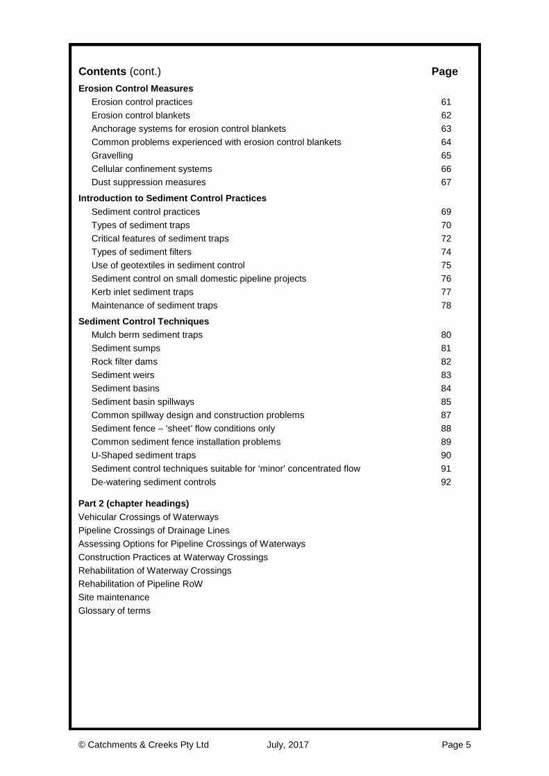
Contents (cont.) Page Erosion Control Measures
Erosion control practices 61 Erosion control blankets 62 Anchorage systems for erosion control blankets 63 Common problems experienced with erosion control blankets 64 Gravelling 65 Cellular confinement systems 66 Dust suppression measures 67
Introduction to Sediment Control Practices Sediment control practices 69 Types of sediment traps 70 Critical features of sediment traps 72 Types of sediment filters 74 Use of geotextiles in sediment control 75 Sediment control on small domestic pipeline projects 76 Kerb inlet sediment traps 77 Maintenance of sediment traps 78
Sediment Control Techniques Mulch berm sediment traps 80 Sediment sumps 81 Rock filter dams 82 Sediment weirs 83 Sediment basins 84 Sediment basin spillways 85 Common spillway design and construction problems 87 Sediment fence – ‘sheet’ flow conditions only 88 Common sediment fence installation problems 89 U-Shaped sediment traps 90 Sediment control techniques suitable for ‘minor’ concentrated flow 91 De-watering sediment controls 92
Part 2 (chapter headings) Vehicular Crossings of Waterways Pipeline Crossings of Drainage Lines Assessing Options for Pipeline Crossings of Waterways Construction Practices at Waterway Crossings Rehabilitation of Waterway Crossings Rehabilitation of Pipeline RoW Site maintenance Glossary of terms

© Catchments & Creeks Pty Ltd July, 2017 Page 6
Purpose of field guide Part 1 of this field guide has been prepared specifically to provide: · the pipeline industry with general guidelines on the management of their construction sites
with respect to soil erosion and the control of sediment runoff · construction personnel working on land-based pipeline projects with general guidelines on
the selection of appropriate construction phase drainage, erosion and sediment controls in the circumstances where an appropriate Erosion and Sediment Control Plan does not exist, or does not adequately address the current site conditions.
This field guide has been prepared specifically for use on large rural pipeline projects. Only parts of the document will be relevant to small domestic pipeline installations.
This guideline has not been prepared for the purpose of being a site’s primary guide to erosion and sediment control. Consequently, the recommendations provided within this field guide should not be used to overrule advice obtained from suitably trained experts, or the recommendations and/or requirements of locally endorsed ESC guidelines/manuals.
It is noted that approximately 45% of the photos presented within this field guide have originated from actual pipelines projects.
About the author Grant Witheridge is a civil engineer with both Bachelor and Masters degrees from the University of NSW. He has over 35 years experience in the fields of hydraulics, stormwater management, creek engineering and erosion & sediment control, during which time he has worked for a variety of federal, state, local government and private organisations.
Grant is the principal author of such publications as the revised Queensland Urban Drainage Manual (2007, 2013 & 2017) and IECA (Australasia) Best Practice Erosion and Sediment Control (2008) documents. In 2010 Grant was presented with the IECA (International) Sustained Contributor Award.
Introduction The three cornerstones of the erosion and sediment control (ESC) industry are drainage control, erosion control, and sediment control. The primary functions of construction phase drainage, erosion, and sediment controls are outlined below: · drainage control measures aim to prevent or reduce soil erosion caused by concentrated
flows (including the management of rill and gully erosion) and to appropriately manage the movement of ‘clean’ and ‘dirty’ water across the site
· erosion control measures aim to prevent or reduce soil erosion caused by raindrop impact and sheet flow (i.e. the control of splash and sheet erosion)
· sediment control measures aim to trap and retain sediment displaced by up-slope erosion processes.
It is noted that on most construction sites, best practice sediment control measures cannot, on their own, provide adequate protection of downstream environments. Therefore, appropriate drainage and erosion control measures must also be applied, at all times, especially on clayey soils. Desirable environmental protection is only achieved when all three ESC measures are working in a coordinated manner during each phase of the construction process.
One of the most notable features of the erosion and sediment control profession is that there is almost always an exception to every rule and guideline. The fact that a control measure is observed to work well on one site does not mean that it will work well on all sites. Similarly, the fact that a control measure has repeatedly failed within one region does not mean that the technique will not be useful within another climatic or topographic region.
Even though erosion and sediment control practices sit at the cutting edge of common sense, their application to a given site must represent an appropriate balance between theory, past experience, and common sense. Also, no rule or recommendation should be allowed to overrule the application of unique, site-specific solutions, where such solutions can be demonstrated to satisfy the stated environmental objectives, and/or the specified performance standards.
© Catchments & Creeks Pty Ltd July, 2017 Page 7
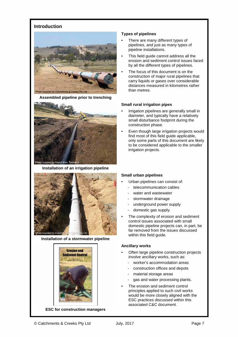
Introduction
Types of pipelines · There are many different types of
pipelines, and just as many types of pipeline installations.
· This field guide cannot address all the erosion and sediment control issues faced by all the different types of pipelines.
· The focus of this document is on the construction of major rural pipelines that carry liquids or gases over considerable distances measured in kilometres rather than metres.
Assembled pipeline prior to trenching
Small rural irrigation pipes · Irrigation pipelines are generally small in
diameter, and typically have a relatively small disturbance footprint during the construction phase.
· Even though large irrigation projects would find most of this field guide applicable, only some parts of this document are likely to be considered applicable to the smaller irrigation projects.
Installation of an irrigation pipeline
Small urban pipelines · Urban pipelines can consist of:
- telecommunication cables - water and wastewater - stormwater drainage - underground power supply - domestic gas supply.
· The complexity of erosion and sediment control issues associated with small domestic pipeline projects can, in part, be far removed from the issues discussed within this field guide.
Installation of a stormwater pipeline
Ancillary works · Often large pipeline construction projects
involve ancillary works, such as: - worker’s accommodation areas - construction offices and depots - material storage areas - gas and water processing plants.
· The erosion and sediment control principles applied to such civil works would be more closely aligned with the ESC practices discussed within this associated C&C document.
ESC for construction managers

© Catchments & Creeks Pty Ltd July, 2017 Page 8
Introduction
Components of soil and sediment · ‘Sediment’ should not be viewed as a
single pollutant. · Sediment runoff from construction sites
can consist of the following pollutants: - clay-sized particles - silt-sized particles - sand-sized particles - cement wash-off - metals and other colloidal particles
often attached to clay particles - organic matter, including weed seed. Components of soil
Fine and coarse sediment · The components of sediment runoff are
often grouped into ‘fine’ and ‘coarse’ sediments.
· Fine sediments consist of clay-sized particles and the finer silts.
· Coarse sediments consist of the coarser silts, and sand-sized particles.
· The finer sediment fraction usually travels as suspended sediment, much of which constitutes water ‘turbidity’ (the brown colouration of stormwater runoff).
On-site deposition of coarse sediment
Impact of coarse and fine sediment · In general, the runoff of coarse sediment
primarily causes human-related problems, such as traffic safety issues, and drainage and flooding problems.
· The runoff of the finer sediment particles generally causes most of the ecological harm, such as damage to aquatic ecosystems.
· Erosion control measures aim to minimise the release of fine sediments, while sediment control practices primarily aim to minimise the release of coarse sediments. Various suspended solids concentrations
Cement wash-off · Cement wash-off can be generated from
various construction activities. · The environmental harm caused by
cement wash-off is primarily linked to the pH (alkalinity) of the liquid waste, not the actual sediment.
· The deposition of cement and concrete waste within urban drainage systems can cause blockages and increase the effective ‘roughness’ of these drainage surfaces, which reduces their hydraulic capacity. Deposition of cement wash-off on a road

© Catchments & Creeks Pty Ltd July, 2017 Page 9
Impacts of soil erosion and sediment runoff
Dust generation · Dust generated on pipeline projects can
cause significant annoyance to neighbouring properties, and can bring undesirable attention to the pipeline industry.
· Excessive dust can cause problems for workers’ health, and in extreme cases, safety problems associated with reduced visibility.
Construction site dust
Blockage of stormwater pipes and drains · Sediment deposition within stormwater
drainage pipes and roadside drains can: - increase flooding and safety risks on
roadways - increase maintenance costs for asset
owners such as local governments - increase the likelihood of mosquito
breeding.
(The sediment deposition shown left originated from an adjacent pipeline installation.)
Sedimentation of drainage pipe
Deposition of sediment on adjacent lands · The deposition of sediment on farmland
and native bushland adjacent to the pipeline Right-of-Way (RoW) can: - adversely affect the natural
passageway of overland stormwater runoff (typically on very flat land)
- spread weed seed - discharge sediment into farm dams.
(The sediment deposition shown left originated from an adjacent pipeline installation.)
Sediment deposition on farmland
Turbidity within farm dams · The release of fine sediments and turbid
water into farm dams can: - adversely affect the water quality of
these water storages - increase the concentration of nutrients
and metals within these waters - increase the cost of maintaining
associated domestic water treatment systems.
Discolouration of farm dam

© Catchments & Creeks Pty Ltd July, 2017 Page 10
Impacts of sediment on waterways
Erosion and sediment impacts on dry gullies · Concentrated stormwater runoff from rural
pipeline projects can cause both erosion and sedimentation problems within shallow drainage lines and gullies.
· Rural lands are often very fragile, and minor increases in stormwater runoff, or the redirection of this runoff, can initiate or aggravate gully erosion within the land down-slope of the pipeline.
Gully erosion along a drainage line
Sediment impacts on minor waterways · The deposition of coarse sediment in
minor waterways, such as creeks, can: - increase the risk of property flooding - cause bank erosion and channel
instabilities - cause the loss of essential aquatic
habitats - increase weed infestation of creeks - increase maintenance costs for the
asset owner, such as the landowner or council.
Deposition of coarse sediment in a creek
Sediment impacts on rivers and estuaries · The release of sediment and turbid water
into rivers and estuaries can: - adversely affect the health and bio-
diversity of aquatic life - increase the concentration of nutrients
and metals - increase the deposition of bed
sediments - reduce light penetration into the water - reduce navigation capabilities along the
waterway. Sediment transportation along a river
Sediment impacts on oceans and bays · The release of fine sediment and turbid
water into oceans can: - adversely affect the health and bio-
diversity of aquatic life - increase the concentration of nutrients - smother coral and aquatic habitats - cause a significant loss of seagrasses.
· The purpose of the above discussion is to identify the wider impacts of fine sediments on the environment—it does not imply that all such impacts originate solely from pipeline projects. Flood-induced sediment release

© Catchments & Creeks Pty Ltd July, 2017 Page 11
Impacts of sediment on different types of minor waterways
Clay-based creeks · The release of coarse sediment can:
- infill permanent pools - smother bed vegetation - promote weed growth - increase maintenance costs.
· The release of turbid water can: - adversely affect the health and bio-
diversity of aquatic life - increase the concentration of nutrients
and metals within water bodies - reduce light penetration into pools.
Highly turbid clay-based watercourse
Sand-based creeks · Sand-based creeks have a naturally high
concentration of coarse sediment (sand) within the bed substrate.
· In general, sand-based creeks are not significantly impacted upon by the inflow of coarse sediment because the bed is formed from such material.
· However, these creeks often have clear base flows that can be severely impacted upon by the release of turbid runoff (fine sediments) from construction activities.
Sand-based watercourse
Gravel-based creeks · Gravel-based creeks can experience the
most severe impacts as a result of sediment inflows.
· In some high-energy streams these sediments can be quickly mobilised.
· The release of sediments can: - infill permanent pools - damage the ecological value of riffles - promote weed growth - adversely affect the health and bio-
diversity of aquatic life. Gravel-based watercourse
Rock-based creeks · Rock-based creeks can experience similar
problems to clay-based creeks; however, these are mostly high-energy streams that can readily re-mobilise deposited sediment.
· Sediment deposition in these creeks can: - infill permanent pools - promote weed growth - adversely affect the health and bio-
diversity of aquatic life - reduce light penetration into pools.
Rock-based watercourse

© Catchments & Creeks Pty Ltd July, 2017 Page 12
On-site impacts of soil erosion
Excess generation of on-site mud · Effective on-site drainage control practices
provide the benefit of reduced site wetness and mud generation.
· Poorly managed sites can be difficult to traffic during wet weather, resulting in costly delays to both the project and contractors.
Truck bogged in wet soil
Damage to the pipeline trench · Inadequate temporary erosion and
drainage control measures can result in severe damage to backfilled trenches.
· Recently backfilled pipe trenches are especially vulnerable to both surface and sub-surface (tunnel) erosion because of the low shear strength of the recently disturbed soil, even if some degree of compaction has been applied to the backfill.
· The risk of these problems occurring increases if the soils are dispersive.
Erosion along a backfilled pipe trench
Damage to access tracks
· Inadequate drainage controls on access tracks can lead to track damage caused by severe rilling.
· Vehicle access tracks formed in dispersive subsoils are highly susceptible to deep rilling as shown left.
Rilling on a maintenance access track
Damage to permanent assets
· In some arid and semi-arid regions, the land can be so erodible that minor changes in the direction and/or concentration of surface runoff can lead to severe gully erosion.
· Such erosion can migrate up the drainage line towards the pipeline infrastructure causing significant property damage.
Gully erosion adjacent processing plant

© Catchments & Creeks Pty Ltd July, 2017 Page 13
Types of soil erosion
Raindrop impact erosion · Raindrops can exert significant force upon
the ground. · The resulting soil erosion is often difficult
to detect and thus is often ignored. · Raindrop impact erosion is a major cause
of the release of fine clay-sized particles resulting in highly turbid (brown) runoff.
· Uncontrolled raindrop impact erosion can easily cause the release of 1 to 2 cm of soil, even during a short construction phase.
Evidence of raindrop impact erosion
Sheet erosion · Sheet erosion is the removal of a thin
layer of surface soil through the actions of raindrop impact and sheet runoff.
· Sheet erosion is likely to occur if storm runoff flows over open soil at a speed greater than approximately walking pace.
· It is noted that the erosion of a 1 cm layer of soil represents the loss of 100 cubic metres of soil per hectare.
· After a distance of around 10 m, sheet erosion is likely to change into rill erosion.
Embankment subject to sheet erosion
Rill erosion · A ‘rill’ is an shallow eroded channel less
than 300 mm deep. · Rill erosion is typically caused by high-
velocity concentrated flows (typically water flowing at a brisk walking pace or faster).
· Rilling can also result from the erosion of a soil dispersion (see below).
· Along with flow velocity, soil compaction and soil chemistry can also influence the degree of rilling.
Rill erosion on an embankment
Chemically induced erosion · Soil chemistry can have a significant
influence on the severity and extent of soil erosion.
· If a soil is dispersive, then it is likely to be highly unstable when wet, resulting in severe, deep rilling (or ‘fluting’ as shown left), tunnel erosion and/or gully erosion.
· As a general guide, if an individual ‘rill’ is significantly deeper than its width, then soil chemistry is likely (not always) to be a significant contributing factor to the soil erosion. Severe rilling known as ‘fluting’

© Catchments & Creeks Pty Ltd July, 2017 Page 14
Types of soil erosion
Tunnel erosion · Tunnel erosion is most commonly formed
when groundwater begins to weep through a series of connected cracks within the soil.
· If the soil is dispersive, then the ongoing removal of soil from these minor sub-surface flow paths can eventually form well-defined tunnels.
· Tunnel erosion is typically an indicator of dispersive or sodic soils, especially if these soils are used as backfill within a pipe trench. Entrance to tunnel erosion
Gully erosion · Gullies are open cuts in the soil that are
greater than 300 mm deep. · Gullies are the inevitable outcome of
expanded rill erosion. · Gully erosion can occur within almost any
soil type, but is most commonly found within dispersive and slaking soils.
(The gully erosion shown left originated from an adjacent gas processing installation.)
Recently formed gully erosion
Mass movement · Mass movement failures are most
commonly associated with land slips and landslides where significant volumes of earth are displaced down a slope through the actions of gravity.
· Mass movement failures also include some forms of bank erosion observed within waterways (watercourse erosion). These forms of watercourse erosion include ‘bank slumping’ and ‘bank undercutting’.
Bank slumping
Wind erosion
· Wind erosion is the displacement of surface soil through the actions of wind.
· It is because of the potential for wind erosion that it would be incorrect for construction personnel to assume that soil erosion was not a concern during dry weather.
· Dust problems can be a common complaint received from those properties that adjoin construction sites.
Wind erosion
© Catchments & Creeks Pty Ltd July, 2017 Page 15
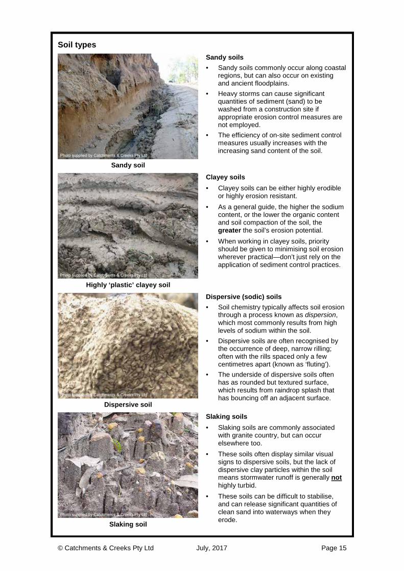
Soil types
Sandy soils · Sandy soils commonly occur along coastal
regions, but can also occur on existing and ancient floodplains.
· Heavy storms can cause significant quantities of sediment (sand) to be washed from a construction site if appropriate erosion control measures are not employed.
· The efficiency of on-site sediment control measures usually increases with the increasing sand content of the soil.
Sandy soil
Clayey soils · Clayey soils can be either highly erodible
or highly erosion resistant. · As a general guide, the higher the sodium
content, or the lower the organic content and soil compaction of the soil, the greater the soil’s erosion potential.
· When working in clayey soils, priority should be given to minimising soil erosion wherever practical—don’t just rely on the application of sediment control practices.
Highly ‘plastic’ clayey soil
Dispersive (sodic) soils · Soil chemistry typically affects soil erosion
through a process known as dispersion, which most commonly results from high levels of sodium within the soil.
· Dispersive soils are often recognised by the occurrence of deep, narrow rilling; often with the rills spaced only a few centimetres apart (known as ‘fluting’).
· The underside of dispersive soils often has as rounded but textured surface, which results from raindrop splash that has bouncing off an adjacent surface.
Dispersive soil
Slaking soils · Slaking soils are commonly associated
with granite country, but can occur elsewhere too.
· These soils often display similar visual signs to dispersive soils, but the lack of dispersive clay particles within the soil means stormwater runoff is generally not highly turbid.
· These soils can be difficult to stabilise, and can release significant quantities of clean sand into waterways when they erode. Slaking soil

© Catchments & Creeks Pty Ltd July, 2017 Page 16
Identifying problematic soils
Soil testing
· With the exception of small, low-risk pipeline installations, appropriate soil testing should be performed prior to initiating any construction works.
· Construction site managers should be aware of those areas along a pipeline corridor that are likely to contain problematic soils, such as highly erodible soils, dispersive or slaking soils, or acid sulfate soils.
Soil analysis
Dispersive and slaking soils · Ideally, dispersive soils should be
identified through appropriate pre-construction soil testing, such as: - exchangeable sodium percentage > 6% - Emerson aggregate classes 1 to 5, note
classes 3(2), 3(1) and 5 have a slight risk of dispersive problems.
· A simple field test such as the Aggregate Immersion Test (see over page) can be used as an on-site indicator test.
· Dispersive soils may also be identified by their distinctive erosion patterns. ‘Fluting’ erosion within a dispersive soil
Acid sulfate soils · Prior to the disturbance of soils below an
elevation of 5 m AHD, the soil should be tested for its acid sulfate potential.
· These soils can already be acidic, or have the potential to become acidic if disturbed.
· Actual and potential acid sulfate soils must be managed in accordance with the local state-approved guidelines.
Culvert damaged by acidic water
Saline soils · Saline soils can introduce complex
revegetation problems, as well as long-term structural problems for pipelines and engineered structures.
· Saline soils can be identified through appropriate soil testing, such as: - electrical conductivity (EC) of either a
1:5 extract > 1.5 dS/m, or a saturated extract > 4 dS/m.
· The management of saline soils requires local expert advice.
Saline soil

© Catchments & Creeks Pty Ltd July, 2017 Page 17
Aggregate Immersion Test
Aggregate Immersion Test · The Aggregate Immersion Test can be
used as an ‘indicator’ of dispersive soils. · This test involves filling a dish with distilled
water (generally available at petrol stations and supermarkets) to a depth sufficient to cover the soil samples.
· Several dry, hard clumps of soil are gently placed in the water.
· The water is then observed for colour changes (after all the air has escaped).
Slightly dispersive soil
Non-dispersive soil · If the water remains clear and the
boundary of the soil clumps remains clearly defined, then the soil is likely to be non-dispersive.
· If the original soil clumps were loose or heavily disturbed, then the soil clumps will likely separate into smaller pieces when first placed into the water—this does not indicate that the soil is dispersive.
· Air escaping from the soil can also cause the clumps to fall apart—this also does not indicate that the soil is dispersive. Non dispersive, non slaking soil
Dispersive soils · If the water discolours both horizontally
and vertically around the soil clumps, then the soil could be dispersive.
· Highly dispersive clumps of soil will collapse in less than 10 minutes.
· Caution; using tap, tank or groundwater can sometimes mask the dispersive reaction due to minerals and/or chemicals in the water.
Dispersive soil
Slaking soils · Slaking soils are soils that readily collapse
in water, but do not necessarily cloud the water.
· If the water remains clear, and the clumps completely collapse and spread horizontally, then the soil could be a slaking soil.
· Slaking soils commonly occur within regions containing granite rock.
· These soils can be highly erodible, especially if disturbed by pipe trenching.
Slaking soil

© Catchments & Creeks Pty Ltd July, 2017 Page 18
Visually identifying dispersive soils
Fluting · In dispersive or sodic soils, the rills
passing down steep banks and batters are normally deep, narrow and regularly spaced—a form of erosion known as ‘fluting’.
Fluting erosion
Tunnel erosion · Tunnel erosion is typically an indicator of
dispersive or sodic soils. · Tunnel erosion can initially appear as just
examples of bank rilling, until further investigations discover that this rilling is directly connected to an up-slope tunnel with the tunnel inlet some metres from the crest of the embankment.
Deep rilling and tunnel erosion
Rilling/fluting only within a band of soil · If the rilling only occurs in a specific region
of the earth batter, then this could mean: - dispersive soils are only present within
this specific band of soil, or - the upper soil may be dispersive, but
has been well sealed and stabilised, or - the soil is not dispersive, but instead
the rilling is the result of excessive flow velocity—in such cases the rills are normally spaced further apart then the dispersive fluting shown left.
Rilling limited to a single band of soil
Rilling/fluting that extends to top of bank · If the rilling extends to the top of the
batter, then this may indicate that the erosion is influenced by run-on water spilling over the bank. In such cases, investigate the drainage conditions up-slope of the earth batter.
· However, this form or rilling may also indicate that the soil is dispersive, which can be confirmed by soil testing.
· If the soils are dispersive (sodic) then they will need to be ameliorated with such chemicals as gypsum. Rilling that extends to top of bank

© Catchments & Creeks Pty Ltd July, 2017 Page 19
Visually identifying slaking soils
Deep rilling with near-vertical sides · When slaking soils and non-cohesive
(sandy) soils first erode, the erosion is often (but not always) deeper than it is wide, and the sides of the rill are often near-vertical.
· This form of erosion can exist if the soil has one or more of the following attributes: - slaking - non-cohesive (sandy) - poorly compacted - very low in organic content.
Deep rilling within a sandy soil
Tunnel erosion · Both dispersive and slaking soils are
susceptible to tunnel erosion if used as backfill within a pipe trench.
Inlet to tunnel erosion in pipe trench
Erosion of compacted backfill · Slaking soils can still be highly erodible
even if firmly compacted, especially if the soil lacks sufficient organic matter, such as a very sandy soil.
Erosion of backfilled pipe trench
Textured surface · Both dispersive and slaking soils can
display textured patterns on those underside surfaces that are not directly exposed to rainfall.
· These surfaces become textured as a result of raindrop splash bouncing off adjacent surfaces.
Bank not exposed to direct rainfall

© Catchments & Creeks Pty Ltd July, 2017 Page 20
Table 1 – Management of problematic soils (may not be practical at all locations) [1]
Soil type Drainage/erosion control Sediment Control Dispersive (sodic) soils
· Avoid ‘cutting’ drainage channels into dispersive soils; instead, divert and channel water using flow diversion banks or topsoil windrows.
· Dispersive soils must be treated with gypsum/lime or buried under a minimum 100–300imm layer of non-dispersive soil before placing any revegetation or erosion control measures.
· Avoid the use of Check Dams in drains containing exposed dispersive soils.
· Dispersive soils usually require the addition of gypsum or similar to improve settlement properties.
· Sediment control usually relies on the use of Type A, B or D Sediment Basins.
· Priority should be given to the application of effective erosion control measures along the RoW, rather than trying to control sediment runoff and turbidity.
· Look for opportunities to release turbid waters as sheet flow over adjacent grassed land.
Non-cohesive sandy soils
· It is essential to control water movement and flow velocity.
· Erosion control may be achieved through Erosion Control Blankets, Soil Binders or Mulch anchored with a suitable tackifier or mesh.
· Long-term erosion control is best achieved with groundcover vegetation such as grass.
· Sediment control measures are most effective in sandy soil areas.
· Grassed Buffer Zones (adjacent to the pipeline) are only effective if sheet flow can be maintained.
· It is important to maximise the ‘surface area’ of sediment control ponds.
Highly erodible clayey soils
· Control flow velocities in diversion drains through the use of Check Dams.
· Short-term erosion control may be achieved with Erosion Control Blankets or Mulching.
· Long-term erosion control is likely to rely on the establishment of a good vegetative cover.
· Give preference to the use of Type-1 & 2 sediment controls over Type-3 sediment controls.
· Sediment control usually relies on the use of Type A, B or D Sediment Basins.
· Priority should be given to the application of erosion control measures.
· Important to maximise the volume of sediment control ponds.
Low fertility soils
· These soils are usually more erodible than fertile soils.
· These soils may be protected with the use of Rock Mulching, unless the soils are modified to allow successful revegetation.
· No special (unique) sediment control requirements exist for these soils.
Potential acid sulfate soils
· Minimise disturbance of the soil. · Where disturbance is necessary,
minimise the duration of exposure, especially for sandy soils.
· Treat exposed soils in accordance with state policies/guidelines.
· Backfill trenches within 24-hours. · Follow local guidelines for site
rehabilitation and revegetation.
· Acidic water may wash from sediment control devices, and this water may need further treatment to adjust the pH.
[1] It can be impractical to apply these measures along the full length of a pipeline corridor.
© Catchments & Creeks Pty Ltd July, 2017 Page 21
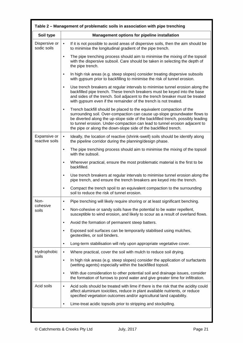
Table 2 – Management of problematic soils in association with pipe trenching
Soil type Management options for pipeline installation
Dispersive or sodic soils
· If it is not possible to avoid areas of dispersive soils, then the aim should be to minimise the longitudinal gradient of the pipe trench.
· The pipe trenching process should aim to minimise the mixing of the topsoil with the dispersive subsoil. Care should be taken in selecting the depth of the pipe trench.
· In high risk areas (e.g. steep slopes) consider treating dispersive subsoils with gypsum prior to backfilling to minimise the risk of tunnel erosion.
· Use trench breakers at regular intervals to minimise tunnel erosion along the backfilled pipe trench. These trench breakers must be keyed into the base and sides of the trench. Soil adjacent to the trench breaker must be treated with gypsum even if the remainder of the trench is not treated.
· Trench backfill should be placed to the equivalent compaction of the surrounding soil. Over-compaction can cause up-slope groundwater flows to be diverted along the up-slope side of the backfilled trench, possibly leading to tunnel erosion. Under-compaction can lead to tunnel erosion adjacent to the pipe or along the down-slope side of the backfilled trench.
Expansive or reactive soils
· Ideally, the location of reactive (shrink-swell) soils should be identify along the pipeline corridor during the planning/design phase.
· The pipe trenching process should aim to minimise the mixing of the topsoil with the subsoil.
· Wherever practical, ensure the most problematic material is the first to be backfilled.
· Use trench breakers at regular intervals to minimise tunnel erosion along the pipe trench, and ensure the trench breakers are keyed into the trench.
· Compact the trench spoil to an equivalent compaction to the surrounding soil to reduce the risk of tunnel erosion.
Non-cohesive soils
· Pipe trenching will likely require shoring or at least significant benching.
· Non-cohesive or sandy soils have the potential to be water repellent, susceptible to wind erosion, and likely to scour as a result of overland flows.
· Avoid the formation of permanent steep batters.
· Exposed soil surfaces can be temporarily stabilised using mulches, geotextiles, or soil binders.
· Long-term stabilisation will rely upon appropriate vegetative cover.
Hydrophobic soils
· Where practical, cover the soil with mulch to reduce soil drying.
· In high risk areas (e.g. steep slopes) consider the application of surfactants (wetting agents) especially within the backfilled topsoil.
· With due consideration to other potential soil and drainage issues, consider the formation of furrows to pond water and give greater time for infiltration.
Acid soils · Acid soils should be treated with lime if there is the risk that the acidity could affect aluminium toxicities, reduce in plant available nutrients, or reduce specified vegetation outcomes and/or agricultural land capability.
· Lime-treat acidic topsoils prior to stripping and stockpiling.

© Catchments & Creeks Pty Ltd July, 2017 Page 22
Management of dispersive soils
Stabilisation of earth batters · Dispersive soils must be:
- treated with gypsum or other appropriate calcium-based material, or
- buried under a minimum 100–300 mm layer of non-dispersive soil before placing any vegetation or erosion control measures.
· The minimum thickness of capping depends on the bank slope and the likelihood of future soil disturbance by stock, vehicles or creek erosion.
Erosion of a dispersive soil
Stabilisation of open drains · Avoid cutting drainage channels into
dispersive soils. · Avoid the use of Check Dams within any
drain that cuts into a dispersive soil. · The use of Check Dams only extends the
duration of water ponding, and thus the risk of erosion.
· Instead, line the drain with a non-dispersive soil and revegetate.
· If very high soil compaction is achieved, then revegetation may not occur.
Failure of a check dam on a dispersive soil
Prevention of tunnel erosion · Dispersive soils are highly susceptible to
tunnel erosion. · Sealing batter chutes (formed in
dispersive soils) with concrete can result in tunnel erosion forming under the concrete.
· Similarly, tunnel erosion can also form under dispersive soil batter chutes lined with rock or rock mattresses.
Tunnel erosion under concrete
Treatment of soil prior to seeding · Do not directly seed an untreated
dispersive soil. · A well-established vegetative root system
cannot prevent the release (dispersion) of clay particles from the soil, which ultimately will undermine the vegetation.
· Instead, treat the soil with gypsum (or the like) and/or cover the dispersive soil with a minimum 100 to 300 mm layer of non-dispersive soil.
· The required depth of cover depends on the likely degree of future soil disturbance. Erosion of recently seeded surface

© Catchments & Creeks Pty Ltd July, 2017 Page 23
Principles of erosion and sediment control
Factors affecting soil erosion · The factors affecting water-induced soil
erosion include: - Rainfall erosivity; the ability of rainfall
to dislodge soil particles - Soil erodibility; the ability of the soil to
resist being eroded - Slope length; the length over which
water flows uninterrupted - Slope grade; the steepness of a slope - Surface cover; ability of the surface
cover to protect soils from erosion - Land management practices
Sheet and rill erosion
Factors affecting sediment runoff · The factors affecting the degree of
sediment runoff from a site include: - Degree of soil erosion; linked to
drainage and erosion controls - Type of sediment controls adopted
on the site – types 1, 2 or 3 controls - Design flow rate of the treatment
train; e.g. 0.5Q1, Q1, Q2, where Q1 = 1 in 1 year design storm
- Percentage of the site’s runoff directed to sediment traps.
Sediment deposition
Management of soil erosion · Each form of soil erosion is generally
controlled by a different land management practice.
· Drainage Control and Erosion Control measures focus on different activities.
· Drainage Control measures focus on the control of soil scour and rill erosion.
· Erosion Control measures focus on the control of splash and sheet erosion.
Techniques used to control soil erosion
Principles of erosion and sediment control The key principles of erosion and sediment control are centred around the following tasks: 1. Minimise disturbance 2. Control site drainage 3. Control soil erosion 4. Promptly revegetate 5. Control sediment runoff 6. Develop effective and flexible ESC Plans 7. Implement ESC Plans and monitor the site
Setting priorities base on site conditions

© Catchments & Creeks Pty Ltd July, 2017 Page 24
Universal Soil Loss Equation (USLE)
USLE & RUSLE · Soil loss rates are most commonly
estimated using the Universal Soil Loss Equation, also known as USLE.
· Over its many years of use the parameters used within the USLE have been modified resulting in the formation of a revised equation.
· The Revised Universal Loss Equation (RUSLE) is now the more commonly used equation; however, both equations take the following form:
A = R . K . LS . C . P Recently cleared RoW
Equation terms The terms used in the USLE equation are: · A = soil loss rate (tonnes/ha/yr) · R = rainfall erosivity factor · K = soil erodibility factor · LS = combined length-slope factor · C = cover and land management factor · P = erosion control practice factor To determine the tonnage (t) of soil loss:
- multiply by the area (ha) and time (yr) To determine the volume (m3) of soil loss:
- divided by the soil density (t/m3) Sediment retained in a sediment trap
Application of RUSLE to construction sites · The USLE/RUSLE formula was originally
developed and calibrated for the assessment of erosion rates on low-gradient rural properties.
· The equation assesses only ‘sheet’ and mild ‘rill’ erosion.
· The equation does not take into account soil dispersion, gully erosion or erosion within creeks and drainage channels.
· The ability of the equation to accurately assess soil loss from a pipeline project is limited, so it must be applied with caution. Steep pipeline RoW
The erosion hazard is linked to the tonnage of soil loss, not the rate (t/ha/yr); thus, the sediment standard is related to both the soil loss rate and area of disturbance (ha), as set out below:
Table 3 – Example sediment control standard for general construction works
© Catchments & Creeks Pty Ltd July, 2017 Page 25
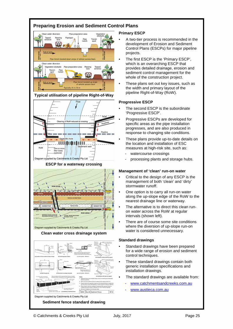
Preparing Erosion and Sediment Control Plans
Primary ESCP · A two-tier process is recommended in the
development of Erosion and Sediment Control Plans (ESCPs) for major pipeline projects.
· The first ESCP is the ‘Primary ESCP’, which is an overarching ESCP that provides detailed drainage, erosion and sediment control management for the whole of the construction project.
· These plans set out key issues, such as the width and primary layout of the pipeline Right-of-Way (RoW). Typical utilisation of pipeline Right-of-Way
Progressive ESCP · The second ESCP is the subordinate
‘Progressive ESCP’. · Progressive ESCPs are developed for
specific areas as the pipe installation progresses, and are also produced in response to changing site conditions.
· These plans provide up-to-date details on the location and installation of ESC measures at high-risk site, such as: - watercourse crossings - processing plants and storage hubs.
ESCP for a waterway crossing
Management of ‘clean’ run-on water · Critical to the design of any ESCP is the
management of both ‘clean’ and ‘dirty’ stormwater runoff.
· One option is to carry all run-on water along the up-slope edge of the RoW to the nearest drainage line or waterway.
· The alternative is to direct this clean run-on water across the RoW at regular intervals (shown left).
· There are of course some site conditions where the diversion of up-slope run-on water is considered unnecessary. Clean water cross drainage system
Standard drawings · Standard drawings have been prepared
for a wide range of erosion and sediment control techniques.
· These standard drawings contain both generic installation specifications and installation drawings.
· The standard drawings are available from: - www.catchmentsandcreeks.com.au - www.austieca.com.au
Sediment fence standard drawing

© Catchments & Creeks Pty Ltd July, 2017 Page 26
Key issues on pipeline projects
Introduction · The preparation of ESCPs for pipeline
projects is primarily based around the following key activities: - diversion of run-on water - manage flow releases from the RoW - interception and diversion of site runoff - treatment of dirty water runoff - control on-site soil erosion - management of waterway crossings - preparing the site for imminent storms - site rehabilitation. ESC measures on a pipeline RoW
Diversion of up-slope run-on water · Wherever practical, ‘clean’ up-slope run-
on water should be diverted away from any disturbed soil.
· In general, stripped topsoil is either placed up-slope of the pipe trench as a clear-water diversion, or placed down-slope of the trench as a dirty-water diversion.
· The risk of soil scour occurring alone diversion drains can be managed with either a channel lining (expensive) or velocity control Check Dams.
Topsoil windrow flow diversion bank
Manage flow releases from the RoW · In some cases, clean run-on water will
need to be carried across the pipeline corridor at regular intervals.
· The spacing of clean-water cross drainage systems depends on: - the specified design storm - the maximum non-erosive hydraulic
capacity of the up-slope drainage system (i.e. the flow diversion banks)
- catchment and soil conditions down-slope of the RoW.
Clean water cross drainage system
Capture and treatment of dirty water runoff · Topsoil windrows can be used to divert
sediment-laden (dirty) runoff to appropriate sediment traps.
· The type of sediment trap (Type-1, 2 or 3) depends on the assessed erosion hazard of a given sub-catchment.
· In some cases, Mulch Berms can be used to both capture, divert and treat sediment-laden runoff.
Sediment trap
© Catchments & Creeks Pty Ltd July, 2017 Page 27
Key issues on pipeline projects
Controlling on-site soil erosion · On-site soil erosion can be controlled by:
- controlling soil erosion that may occur along flow diversion drains or berms
- stabilising batter drains - stabilising long-term stockpiles,
windrows and berms - staging land clearing, pipe installation,
and site rehabilitation to minimise the duration that disturbed soils are exposed to wind and rainfall.
Site revegetation
Management of drainage line crossings · Pipeline crossings of drainage lines and
waterways requires special care. · Various construction methods are
available for crossing waterways including: - open trench techniques: plough, open
cut trench, dragline or dredging - cofferdams and two-stage open
trenching behind impervious isolation barriers
- trenchless techniques and horizontal directional drilling.
Pipeline crossing of a waterway
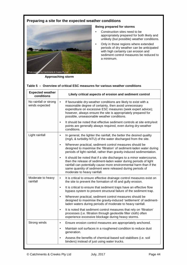
Preparing for imminent storms · A well-managed site is one that is
prepared for both likely and unlikely (but possible) weather conditions.
· Only in those regions where extended periods of dry weather can be anticipated with certainty can erosion and sediment control measures be reduced to a minimum.
· Typical responses to imminent storms should be detailed within the Primary Erosion and Sediment Control Plan.
Approaching storm
Post-construction site rehabilitation · Final site rehabilitation measures may be
detailed on plans separate to the suite of Erosion and Sediment Control Plans.
· However, it is usually for the ESCP to provide details on: - temporary site revegetation measures
in the event of an unplanned site shut-down
- timing of site revegetation relative to the time of year or assessed erosion risk
- method of plant establishment. Rehabilitation of pipeline RoW

© Catchments & Creeks Pty Ltd July, 2017 Page 28
Site Establishment and Operation

© Catchments & Creeks Pty Ltd July, 2017 Page 29
Site establishment
Pre-construction meetings · The erosion and sediment control
outcomes of a pipeline project can benefit greatly from appropriate site planning.
· Critical discussion topics include the layout of the RoW, the progression of land clearing relative to pipe installation, and the management of waterway crossings.
· Pre-construction meetings can help to ensure all parties are aware of the critical issues associated with any new works.
Site meeting
Set-up of site office · Site entry points should be limited to the
minimum number of locations. · Stabilise all site entry and exit points as
appropriate for the type of vehicle movement and soil conditions.
· Wherever practical, ensure stormwater runoff from buildings and sheds will not cause unnecessary soil erosion or the generation of mud, especially around heavy traffic areas.
Site entry and office
On-site storage of emergency materials · Stockpile all necessary materials to
establish and maintain the site’s erosion and sediment control (ESC) measures.
· Maintain adequate supplies of emergency ESC materials such as: straw bales, wire, stakes, sediment fence fabric, filter cloth, wire mesh, and clean aggregate.
· The materials shown in the photo (left) are jute blanket (top), shade cloth (not used for erosion or sediment control), and filter cloth (bottom).
Storage of various construction fabrics
Concrete wash-out points · If significant concreting is to occur on the
site, then establish a concrete disposal area lined with plastic sheeting, permeable earth filter-banks, or other appropriate filter materials.
· Ensure these areas are clearly visible or well signed so that contractors and delivery drivers will be able to identify their location.
Concrete truck wash-out point

© Catchments & Creeks Pty Ltd July, 2017 Page 30
Site management
Staff training · Site induction courses need to incorporate
information on environmental management and incident reporting.
· Ensure employees receive adequate training on: - environmental management - best practice erosion and sediment
control practices - incident reporting procedures - site inspection and maintenance
procedures (selected staff only). On-site training
Site inspections · Nominate the officer(s) responsible for the
inspection of on-site erosion and sediment control measures.
· Establish an appropriate site inspection routine, as well as maintenance and reporting procedures.
· Identification tags, such as strips of filter cloth stapled to sediment fence fabric (shown left), can be used to identify those ESC measures requiring maintenance.
Damaged fence tagged for repair
Water quality testing · Identify the target water quality objectives
(WQOs) for the site. · WQOs are normally assigned by the state
or local government. · Typical water quality objectives are:
- 50 mg/L of total suspended solids - a turbidity level no greater than 10%
above that of the receiving water - water pH in the range 6.5 to 8.5
· Only appropriately trained people should collect and test water samples. Examples of suspended solids content
Reporting of environmental harm · Best practice site management requires
establishment of appropriate incident reporting procedures, including: - identifying the chain of responsibility - procedures for recording areas of non-
compliance - monthly reporting procedures (if
required) - procedures for recording corrective
actions - internal recording and filing procedures.
Fish kill in an adjacent waterway

© Catchments & Creeks Pty Ltd July, 2017 Page 31
Site inspection and monitoring
Regular site inspections · All erosion and sediment control measures
should be inspected: - at least daily when rain is occurring
(when it is safe to do so) - at least weekly (even if work is not
occurring on-site) - within 24 hours prior to expected rainfall - within 18 hours of a rainfall event of
sufficient intensity to cause runoff. · A formal Site Checklist should be
completed weekly or monthly. Storm damage to sediment fence
Collection of water samples · Site inspections need to be conducted
during both dry and wet weather. · On large pipeline installations, regular
third-party site inspections should occur. · On large or high-risk sites, monitoring is
likely to include specific water quality sampling and detailed logbook entries of the site’s monitoring and maintenance activities.
Upstream & downstream water samples
Investigate the source of sediment runoff · When a site inspection detects a notable
failure in the adopted ESC measures, the source of this failure must be investigated, and appropriate amendments made to the site and the ESC plans.
· If the site inspection identifies that a revised ESCP is required, then while this plan is being prepared, site personnel should take appropriate steps to minimise the risk of environmental harm—waiting for the revised plan to arrive is not a reason for delaying reasonable actions.
Deposition of sediment in a storm drain
Responding to poor test results · Erosion and Sediment Control Plans
(ESCPs) are living documents that can and should be modified if: - site conditions change, or - the adopted measures fail to achieve
the required treatment standard (e.g. the water quality objectives).
· Site monitoring and inspections can form the key difference between the initial ‘Primary ESCP’ and the subsequent ‘Progressive ESCPs’.
Erosion & Sediment Control Plan

© Catchments & Creeks Pty Ltd July, 2017 Page 32
Site entry and exit points
Stabilised site entry/exit points · Stabilised site entry/exit conditions are
generally only required if the entry/exit point abuts a sealed roadway.
· However, even if the site abuts an unsealed roadway, sediment-laden water should not be allowed to freely discharge from the work site at these locations.
· Divided entry and exit points only work if they can be properly controlled, otherwise, the temptation is for trucks to bypass the sediment control system and exit via the entry lane.
Divided site entry and exit lanes
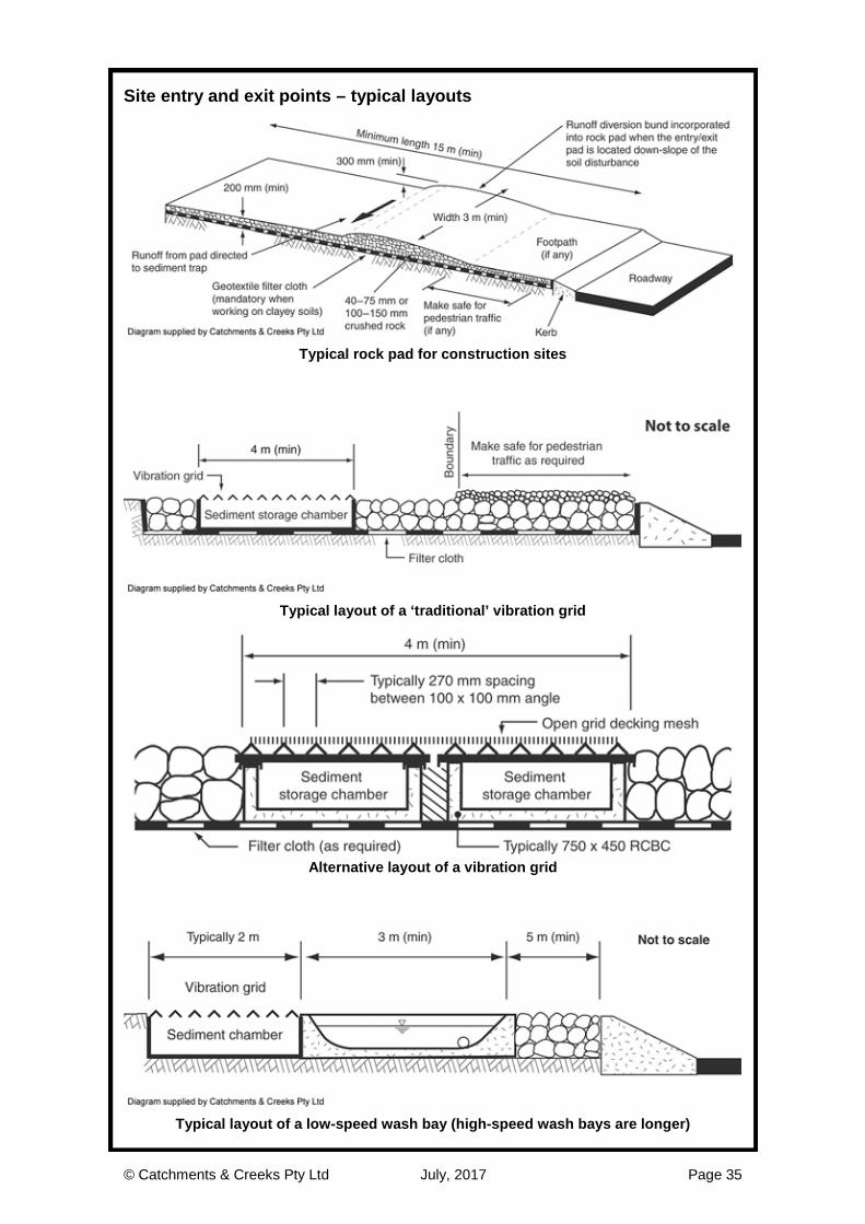
Rock pads · Rock entry/exit pads are suitable for all
soil types. · The critical design parameter is the total
void spacing volume between the rocks. · Minimum 15 m length. · The width of the rock pad is usually not
critical. · Requires a geotextile underlay. · Rock pads generally perform better than
Vibration Grids during wet weather.
Rock pad
Rock selection · A uniform rock size is required to
maximise the void spacing. · Rock sizes of:
- 40 to 75 mm, or - 100 to 150 mm.
· Rock sizes of 75 to 100 mm are generally avoided because they can become wedged between dual tyres and transported off the site.
Site signage
Drainage controls on rock pads · Runoff from the rock pad must be directed
away from public roads. · Drainage controls (e.g. cross banks,
speed control berms) may need to be incorporated into the rock pad to direct sediment-laden runoff to an appropriate sediment trap.
· A drainage pipe (culvert) may need to be installed below the cross bank to carry ‘clean’ run-on water under the rock pad.
Sediment-laden flow directed off rock pad

© Catchments & Creeks Pty Ltd July, 2017 Page 33
Site entry and exit points – Vibration grids
Vibration grids · Vibration grids are best suited to sandy
soils. · They can also be used in clayey soil
regions to control sediment movement from heavy construction traffic during periods of dry weather.
Vibration grid
Incorporation of gravel pad · A gravel pad must extend from the grid to
the sealed roadway to prevent the re-contamination of the vehicle tyres.
· Appropriate measures (fencing, flagging, etc) may need to be employed to ensure vehicles don’t bypass the vibration grid.
Vibration grid
Modified vibration grid design · Welding reinforcing mesh over a standard
vibration grid can reduce potential damage to construction vehicles caused by strong vibrations.
Vibration grid
Clean-out pits · It is essential for vibration grids to be
raised well above the ground to allow the collection of sediment below the grid.
· Up-turned box culverts can be used as sediment collection and clean-out troughs.
Sediment storage below vibration grid
© Catchments & Creeks Pty Ltd July, 2017 Page 34
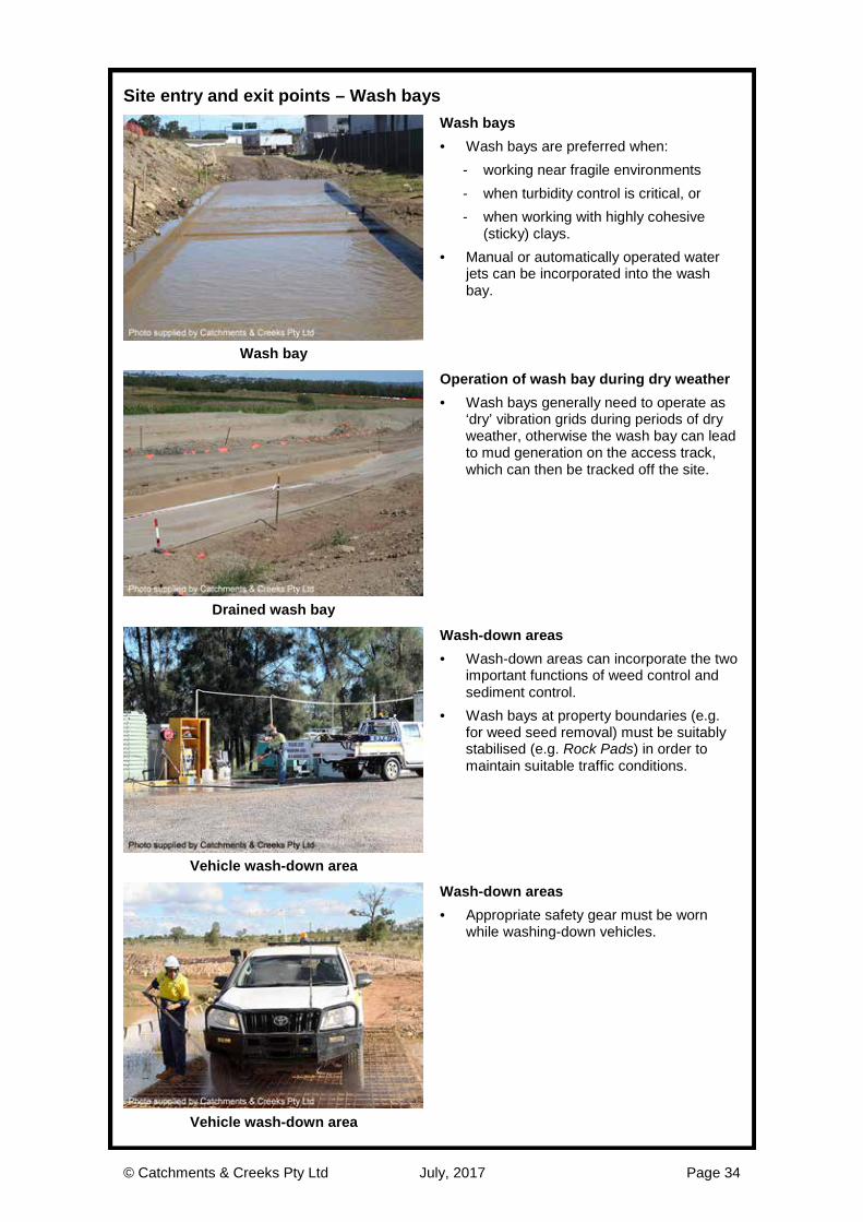
Site entry and exit points – Wash bays
Wash bays · Wash bays are preferred when:
- working near fragile environments - when turbidity control is critical, or - when working with highly cohesive
(sticky) clays. · Manual or automatically operated water
jets can be incorporated into the wash bay.
Wash bay
Operation of wash bay during dry weather · Wash bays generally need to operate as
‘dry’ vibration grids during periods of dry weather, otherwise the wash bay can lead to mud generation on the access track, which can then be tracked off the site.
Drained wash bay
Wash-down areas · Wash-down areas can incorporate the two
important functions of weed control and sediment control.
· Wash bays at property boundaries (e.g. for weed seed removal) must be suitably stabilised (e.g. Rock Pads) in order to maintain suitable traffic conditions.
Vehicle wash-down area
Wash-down areas · Appropriate safety gear must be worn
while washing-down vehicles.
Vehicle wash-down area
© Catchments & Creeks Pty Ltd July, 2017 Page 35
Site entry and exit points – typical layouts
Typical rock pad for construction sites
Typical layout of a ‘traditional’ vibration grid
Alternative layout of a vibration grid
Typical layout of a low-speed wash bay (high-speed wash bays are longer)

© Catchments & Creeks Pty Ltd July, 2017 Page 36
Minimising the extent and duration of disturbance
Land clearing · The timing of soil disturbances along the
pipeline corridor is critical. · Land clearing should proceed just ahead
of the pipe installation so as to minimise the duration of soil exposure to rainfall.
· The extent of active land clearing should be inversely proportional to the expected monthly rainfall.
· Land clearing should not occur unless immediately preceded by the installation of all necessary drainage and sediment control measures. Cleared pipeline RoW
Staging of land clearing · Land clearing should be staged to
minimise the extent and duration of soil exposure.
· Land clearing on steep slopes and waterway banks must be delayed for as long as possible.
· Progressive land clearing also improves the ‘natural’ relocation of wildlife.
Land clearing adjacent waterway crossing
Delayed removal of tree roots · If vegetation clearing must be carried out
well in advance of earthworks, then this clearing should be limited to the removal of aboveground woody material only.
· Wherever possible, the grubbing and the removal of any ground cover (mulch or vegetation) should not commence until immediately prior to pipeline trenching.
Land clearing without soil disturbance
Protection of retained vegetation · Be prepared to narrow the pipeline RoW
adjacent to critical habitat trees—the approval of a RoW width does not mean that such a width must be cleared at all locations.
· Establish Tree Protection Zones around critical vegetation.
· Ideally, the protection zone should extend from the tree trunk, a minimum of 10 trunk diameters (measured 1 m from the ground) or the width of the tree canopy at its widest point (whichever is greater). Vegetation protection

© Catchments & Creeks Pty Ltd July, 2017 Page 37
Management of cleared vegetation
Stockpiling tree debris · Cleared vegetation can either be:
- stockpiled for later use during the revegetation of the RoW
- mulched for use as a ‘clean’ water flow diversion bank
- mulched for use as a ‘dirty’ water flow diversion bank
- mulched for use as a mulch berm sediment trap.
· Certain weed species may need to be buried or treated.
Cleared vegetation
Tub grinding vs chipping · Vegetation can be mulched using either:
- mulch chipper - tub grinder
· Chipping the vegetation produces a mulch that can be easily spread with a ‘blower’, but can also be easily washed away by stormwater runoff.
· Tub grinding produces a more hydraulically-stable mulch that can be used to form Mulch Berms and this process typically produces less tannins than chipping. Tub grinder
Beneficial use of mulch on site · Mulch berms can be used to divert either
clean run-on water, or site-generated dirty water.
· The mulch should not be totally ‘clean’, but should contain a small proportion of topsoil (generated from the mulching of tree roots) to help stabilise the mulch.
· If high flow velocities are expected adjacent to the mulch berm, then Check Dams can be formed adjacent to the berm to slow these flows.
Mulch berm
Use of tree debris · Tree debris can also be used during site
stabilisation to: - help provide a seed source for native
regeneration (certain species may not be desirable along the RoW)
- act as a drainage control system on steep slopes helping to slow stormwater runoff
- act as a form of ground cover - assist wildlife to migrate across the
RoW during the revegetation phase. Placement of tree debris over RoW

© Catchments & Creeks Pty Ltd July, 2017 Page 38
Topsoil stripping and stockpiling
Topsoil stripping · Best practice topsoil management
includes: - testing topsoils for their nutrient
properties and revegetation potential - appropriate application of soil
ameliorants prior to stockpiling - appropriate stripping and stockpiling - appropriate scarification and treatment
of subsoils prior to topsoil replacement - appropriate application of the remaining
soil ameliorants prior to revegetation. Scraper stripping soil
Stripping topsoils · Stripped topsoil should be preserved for
reuse wherever possible. · Highly contaminated topsoil may need to
be buried. · Topsoil should not be stripped when it is
either too wet or too dry: - too wet means water can be squeezed
from the soil - too dry means the soil readily crumbles
when handled, or the soil cannot be formed into a clump when compressed.
Soil being worked when it is too wet
Poor quality topsoils · The RoW may contain poor quality
topsoils due to weed infestation, low nutrient concentrations, or the effects of past land management practices.
· Rural pipelines often extend across heavily degraded land where the original topsoil has been eroded away.
· The appropriate management of topsoil is critical for the long-term success of site rehabilitation—seek expert advice from a soil science professional.
Poor quality topsoil
Stockpiling topsoil along the RoW · In pipeline projects, topsoils are rarely
stockpiled in isolated mounds, rather they are formed into topsoil windrows that stretch along the length of the RoW.
· These windrows can be used to control the movement of either clean run-on water, or site-generated dirty runoff.
· At watercourse crossings, the windrows should be terminated well away from possible stream flows (the minimum distance may vary with the time of year).
Topsoil windrow down-slope of RoW

© Catchments & Creeks Pty Ltd July, 2017 Page 39
Topsoil management
Topsoil management · Pipeline projects usually benefit from the
fact that the topsoil is usually stripped, stockpiled and respread all at the same location, thus topsoil is not moved along the RoW.
· However, the quality of the topsoil can vary significantly from site to site, and even along a pipeline RoW, consequently the management approach must also vary.
Topsoil stockpile Table 4 – General recommendations for the management of topsoil stockpiles
Condition of topsoil Recommended stockpiling requirements
Topsoils containing valuable native seed content that needs to be preserved for re-establishment
· The upper 50 mm of topsoil should be stockpiled separately in mounds 1.0 to 1.5 m high (this may only be practical at waterway crossings).
· Topsoil more than 50 mm below the surface stockpiled in mounds no higher than 1.5 to 3 m.
· The duration of stockpiling should be the minimum practical, but ideally less than 12 months.
Topsoil containing minimal desirable or undesirable seed content
· Maximum desirable stockpile height of 2 m.
· The duration of stockpiling should be the minimum practical, but ideally less than 12 months.
Topsoils containing significant undesirable weed seed content (very difficult to manage on long pipeline projects)
· Seek local expert advice.
· Consider burying the topsoil or integrating the topsoil into trench breakers if subsoils are dispersive.
· Consider replacing the topsoil with a compost blanket.
· Do not take actions that would ultimately leave subsoils exposed along the RoW.
Topsoils containing weed seed of a declared noxious or otherwise highly undesirable plant species
· Suitably bury the topsoil on-site, or remove the soil from the site for further treatment in accordance with local and state laws.
· Stripped soil must not be transported off-site without appropriate warnings and identification.
Previously disturbed sites where the existing surface soil consists of a mixture of topsoil and dispersive subsoil
· Mix the soil with gypsum, lime or other appropriate ameliorants prior to stockpiling in either high or low mounds according to required protection of its seed content. Adding the ameliorants prior to stockpiling allows time for chemical changes to occur.
In-situ surface material includes a natural layer of gravels and sparse organic litter, such as often found in arid and semi-arid environments
· Collect and stockpile the surface gravels separately from the topsoil.
· Replace the gravels and organic litter over the finished surface of the RoW consistent with its original surface condition.

© Catchments & Creeks Pty Ltd July, 2017 Page 40
Pipeline Right of Way (RoW)
Right of Way (RoW) width · Great care and thought must be given to
the determination of the RoW width. · Note: the base width of topsoil windrows
usually varies with the width of the RoW. · Note: the base width of the trench spoil
stockpile usually varies with the width and depth of the pipe trench.
· Flexible pipes (including steel) often need a separate preparation area, while solid (concrete) pipes may not need this additional clearance width.
Pipeline prior to trenching
Typical layout of a rural pipeline RoW
Layout of the RoW · The layout of the RoW will vary depending
on whether the pipe trench is located up-slope or down-slope of the vehicle access track.
· In response to these variations, the topsoil windrow can be used as either a ‘clean’ water diversion, ‘dirty’ water diversion, or both.
· The width of the cleared RoW should be reduced at watercourse crossings to remove the need for a ‘passing lane’.
Pipeline prior to trenching
Pipe preparation prior to trenching

© Catchments & Creeks Pty Ltd July, 2017 Page 41
Access roads outside the RoW
Drainage and erosion controls · Stormwater runoff (and run-on water) must
be allowed to freely discharge from unsealed roads located outside the pipeline corridor.
· Appropriate drainage controls will be required on all unsealed roads, even if the road is temporary.
· Gravelling of long-term, unsealed roadways can significantly reduce the release of fine sediments and turbid runoff from the roadway.
Permanent maintenance access road
Out-fall drainage · Out-fall drainage is only used when road
runoff can sheet evenly off the road. · Out-fall drainage can cause erosion
problems if: - the outer embankment is unstable, or - an earth windrow is likely to form along
the outer edge of the roadway.
Gravel road with out-fall drainage
In-fall drainage · In-fall drainage is generally the preferred
road drainage system, especially when: - the outer road embankment consists of
poor or unstable soils, or - an earth windrow is likely to form along
the outer edge of the road, e.g. during road grading operations.
Dirt road with in-fall drainage
Cross drainage structures · Cross banks can be used to direct
stormwater runoff across the road to a stable outlet.
· The typical spacing of cross banks on unsealed roads (not on RoW) is: - 120 m for road grades less than 2% - 60 m for road grades of 2 to 4% - 30 m for road grades of 4 to 8% - 15 m for road grades greater than 8%
· The occurrence of erosion on the road, or within the table drain, is a likely indicator of insufficient drainage control. Cross bank drainage

© Catchments & Creeks Pty Ltd July, 2017 Page 42
Access tracks within the RoW
Vehicle access along the RoW · Vehicle access is required along the
pipeline RoW in order to: - access the construction site - deliver pipes and materials.
· Sufficient space must be provided along the access track to allow vehicles to pass the active construction area.
· Stormwater runoff from the access track should be directed to a suitable sediment trap.
Vehicle access along the pipeline RoW
Surface condition of access tracks · Typically the vehicle access track located
with the pipeline RoW remains unsealed. · Stabilisation of the access track may be
required in steep sections (10 to 18%). · Rock stabilisation of the track surface is
usually required if the gradient exceeds 18% (1:5.6 or 10-degrees).
· Tracks formed in non-cohesive sandy soils can be subject to erosion even at low surface gradients.
Sandy access track
Cross drainage structures · Similar to access roads, cross banks are
used on the pipeline RoW to both: - direct stormwater runoff off the RoW - carry excess up-slope run-on water
across the RoW. · The difference between an access road,
and vehicle access along the pipeline RoW, is that vehicle speeds along an access road are usually higher, and therefore the cross banks usually have a more gradual gradient change (i.e smoother approach and descent). Dual uses of cross banks on RoW
Proper drainage of cross banks · Cross banks (berms) should have a broad
base width of 6 to 10 m, a compacted height of 0.6 m (at time of construction), and gentle approach and departure gradients.
· It is essential for the cross bank to be formed with positive drainage gradients (e.g. 1% fall) that will allow the bank to drain freely.
· Water should not be allowed to pool up-slope of the cross bank.
Water pooling at a cross bank

© Catchments & Creeks Pty Ltd July, 2017 Page 43
Managing damage to access tracks
Sunken roads · A common problem experienced in rural
areas is the ‘sunken road’—that being when the road surface is below the natural ground level either side of the road.
· In such cases the road becomes a drainage channel and stormwater is not able to discharge from the road at regular intervals.
· The road and/or down-slope shoulder should be re-graded in order to allow water to discharge from the road at regular intervals. Sunken access road
Sodic soils on steep slope · Access roads that pass directly down a
slope will collect less run-on water, but the road gradients will be steeper.
· If the exposed soil is dispersive (sodic) then severe erosion can occur, even if the road is subject to only minor surface flow.
· Consider ‘boxing out’ the road, treated the removed soil with gypsum, then reforming the road.
· If possible, introduce new material or rock to bulk-up the volume of the returned soil.
Steep, dispersive soil access track
Non-cohesive, slaking soils · Slaking soils can be highly erodible, but
may not produce the highly turbid (brown) runoff associated with dispersive soils.
· Roads and pipe trenches formed in slaking or sandy soils can be subject to severe gully erosion during storms.
· It is very important to form new cross drains, and reinstate old cross drainage berms, prior to imminent storms.
· Consider installing regular buried Rock Checks or trench breakers along the pipe trench. Erosion along a slaking soil trench
Cross drainage erosion · Roads and tracks are often subject to
erosion at locations where concentrated run-on water is allowed to pass across the road.
· This erosion often starts at the point where the runoff spills off the road, i.e. at the point where the flow begins to accelerate.
· All cross drainage points must have stable outlets—this may require the formation of a rock pad, drainage chute, or a recessed log Level Spreader.
Rill erosion across an access track
© Catchments & Creeks Pty Ltd July, 2017 Page 44
Preparing a site for the expected weather conditions
Being prepared for storms · Construction sites need to be
appropriately prepared for both likely and unlikely (but possible) weather conditions.
· Only in those regions where extended periods of dry weather can be anticipated with high certainty can erosion and sediment control measures be reduced to a minimum.
Approaching storm Table 5 – Overview of critical ESC measures for various weather conditions
Expected weather conditions Likely critical aspects of erosion and sediment control
No rainfall or strong winds expected
· If favourable dry-weather conditions are likely to exist with a reasonable degree of certainty, then avoid unnecessary expenditure on excessive ESC measures (seek expert advice); however, always ensure the site is appropriately prepared for possible, unseasonable weather conditions.
· It should be noted that effective sediment controls at site entry/exit points are generally always required, even during dry-weather conditions.
Light rainfall · In general, the lighter the rainfall, the better the desired quality (mg/L & turbidity-NTU) of the water discharged from the site.
· Wherever practical, sediment control measures should be designed to maximise the ‘filtration’ of sediment-laden water during periods of light rainfall, rather than gravity-induced sedimentation.
· It should be noted that if a site discharges to a minor watercourse, then the release of sediment-laden water during periods of light rainfall can potentially cause more environmental harm than if the same quantity of sediment were released during periods of moderate to heavy rainfall.
Moderate to heavy rainfall
· It is critical to ensure effective drainage control measures exist on the site to prevent the formation of rill and gully erosion.
· It is critical to ensure that sediment traps have an effective flow bypass system to prevent structural failure of the sediment trap.
· Wherever practical, sediment control measures should be designed to maximise the gravity-induced ‘settlement’ of sediment-laden waters during periods of moderate to heavy rainfall.
· It is noted that sediment control measures that rely on ‘filtration’ processes (i.e. filtration through geotextile filter cloth) often experience excessive blockage during heavy storms.
Strong winds · Ensure erosion control measures are appropriately anchored.
· Maintain soil surfaces in a roughened condition to reduce dust generation.
· Assess the benefits of chemical-based soil stabilises (i.e. soil binders) instead of just using water trucks.
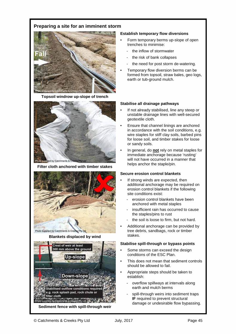
© Catchments & Creeks Pty Ltd July, 2017 Page 45
Preparing a site for an imminent storm
Establish temporary flow diversions · Form temporary berms up-slope of open
trenches to minimise: - the inflow of stormwater - the risk of bank collapses - the need for post storm de-watering.
· Temporary flow diversion berms can be formed from topsoil, straw bales, geo logs, earth or tub-ground mulch.
Topsoil windrow up-slope of trench
Stabilise all drainage pathways · If not already stabilised, line any steep or
unstable drainage lines with well-secured geotextile cloth.
· Ensure that channel linings are anchored in accordance with the soil conditions, e.g. wire staples for stiff clay soils, barbed pins for loose soil, and timber stakes for loose or sandy soils.
· In general, do not rely on metal staples for immediate anchorage because ‘rusting’ will not have occurred in a manner that helps anchor the staple/pin. Filter cloth anchored with timber stakes
Secure erosion control blankets · If strong winds are expected, then
additional anchorage may be required on erosion control blankets if the following site conditions exist: - erosion control blankets have been
anchored with metal staples - insufficient rain has occurred to cause
the staples/pins to rust - the soil is loose to firm, but not hard.
· Additional anchorage can be provided by tree debris, sandbags, rock or timber stakes. Blankets displaced by wind
Stabilise spill-through or bypass points · Some storms can exceed the design
conditions of the ESC Plan. · This does not mean that sediment controls
should be allowed to fail. · Appropriate steps should be taken to
establish: - overflow spillways at intervals along
earth and mulch berms - spill-through weirs into sediment traps
IF required to prevent structural damage or undesirable flow bypassing.
Sediment fence with spill-through weir
© Catchments & Creeks Pty Ltd July, 2017 Page 46
Drainage Control Measures

© Catchments & Creeks Pty Ltd July, 2017 Page 47
Drainage control practices
Purpose of drainage controls · The aims of on-site drainage control are:
- to prevent rill erosion - prevent hydraulic damage to the
various erosion and sediment controls - control the volume, location and
velocity of flow through the work site - control the movement of 'clean' run-on
water passing across the RoW. · The importance of good drainage controls
increases with increasing rainfall potential and decreasing soil strength.
Storm damage to pipe trench
Calculation of flow velocity · The average flow velocity in a drain may
be calculated using Manning’s equation:
V = (1/n) . R 2/3 . S 1/2 where:
V = average flow velocity (m/s) n = Manning’s roughness coefficient R = hydraulic radius (m) = A/P A = effective flow area of channel (m2) P = wetted perimeter of flow (m) S = channel slope (m/m)
Channel geometry and flow conditions
Use of technical specialists · Choosing an appropriate value for the
Manning’s roughness (n) requires experience and training.
· Hydraulic analysis is best carried out by experienced stormwater engineers.
· Critical structures, such as sediment basin spillways, must be designed by a qualified hydraulic/stormwater engineer.
· Warning; poor drainage design can result in significant damage to the pipeline trench, as well as the environment.
Poor sediment basin spillway design
Allowable flow velocity · Drainage channels are designed to
achieve an average flow velocity below the scour velocity of the surface material.
· This design velocity is referred to as the allowable flow velocity.
· Typical design values are: - 1.5 to 2.0 m/s for grass-lined channels - 1.5 to 3.0 m/s for 100 to 350 mm rock - 1.3 to 5.0 m/s for channels lined with
erosion control mats (depends on type of mat).
Temporary diversion drain
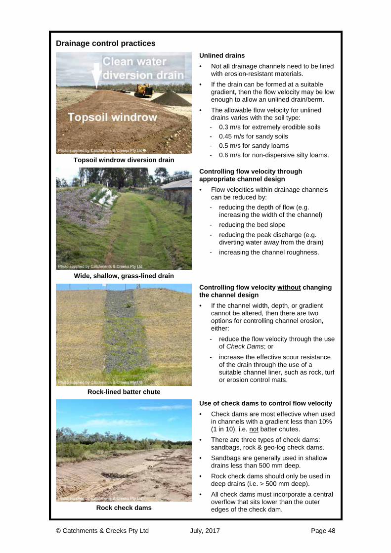
© Catchments & Creeks Pty Ltd July, 2017 Page 48
Drainage control practices
Unlined drains · Not all drainage channels need to be lined
with erosion-resistant materials. · If the drain can be formed at a suitable
gradient, then the flow velocity may be low enough to allow an unlined drain/berm.
· The allowable flow velocity for unlined drains varies with the soil type: - 0.3 m/s for extremely erodible soils - 0.45 m/s for sandy soils - 0.5 m/s for sandy loams - 0.6 m/s for non-dispersive silty loams.
Topsoil windrow diversion drain
Controlling flow velocity through appropriate channel design · Flow velocities within drainage channels
can be reduced by: - reducing the depth of flow (e.g.
increasing the width of the channel) - reducing the bed slope - reducing the peak discharge (e.g.
diverting water away from the drain) - increasing the channel roughness.
Wide, shallow, grass-lined drain
Controlling flow velocity without changing the channel design · If the channel width, depth, or gradient
cannot be altered, then there are two options for controlling channel erosion, either: - reduce the flow velocity through the use
of Check Dams; or - increase the effective scour resistance
of the drain through the use of a suitable channel liner, such as rock, turf or erosion control mats.
Rock-lined batter chute
Use of check dams to control flow velocity · Check dams are most effective when used
in channels with a gradient less than 10% (1 in 10), i.e. not batter chutes.
· There are three types of check dams: sandbags, rock & geo-log check dams.
· Sandbags are generally used in shallow drains less than 500 mm deep.
· Rock check dams should only be used in deep drains (i.e. > 500 mm deep).
· All check dams must incorporate a central overflow that sits lower than the outer edges of the check dam. Rock check dams
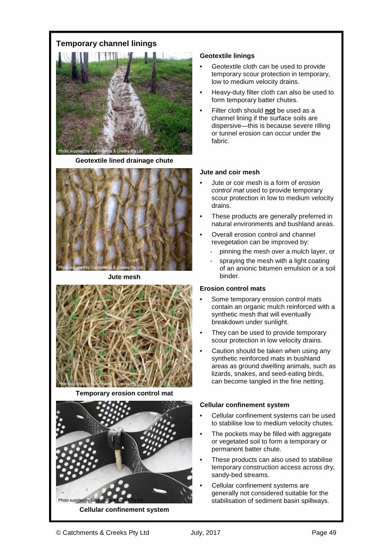
© Catchments & Creeks Pty Ltd July, 2017 Page 49
Temporary channel linings
Geotextile linings · Geotextile cloth can be used to provide
temporary scour protection in temporary, low to medium velocity drains.
· Heavy-duty filter cloth can also be used to form temporary batter chutes.
· Filter cloth should not be used as a channel lining if the surface soils are dispersive—this is because severe rilling or tunnel erosion can occur under the fabric.
Geotextile lined drainage chute
Jute and coir mesh · Jute or coir mesh is a form of erosion
control mat used to provide temporary scour protection in low to medium velocity drains.
· These products are generally preferred in natural environments and bushland areas.
· Overall erosion control and channel revegetation can be improved by: - pinning the mesh over a mulch layer, or - spraying the mesh with a light coating
of an anionic bitumen emulsion or a soil binder. Jute mesh
Erosion control mats · Some temporary erosion control mats
contain an organic mulch reinforced with a synthetic mesh that will eventually breakdown under sunlight.
· They can be used to provide temporary scour protection in low velocity drains.
· Caution should be taken when using any synthetic reinforced mats in bushland areas as ground dwelling animals, such as lizards, snakes, and seed-eating birds, can become tangled in the fine netting.
Temporary erosion control mat
Cellular confinement system · Cellular confinement systems can be used
to stabilise low to medium velocity chutes. · The pockets may be filled with aggregate
or vegetated soil to form a temporary or permanent batter chute.
· These products can also used to stabilise temporary construction access across dry, sandy-bed streams.
· Cellular confinement systems are generally not considered suitable for the stabilisation of sediment basin spillways.
Cellular confinement system

© Catchments & Creeks Pty Ltd July, 2017 Page 50
Anchorage systems for erosion control mats
Timber pegs and stakes · Short timber pegs can be used in a wide
variety of soils. · Typically used to anchor turf placed in
areas likely to experience high-velocity flows soon after turf placement (instead of using metal staples).
· Stakes can be used to anchor erosion control blankets, especially if storms or strong winds are imminent.
· Caution; if used along drainage lines, flood debris can wrap around stakes.
Timber stakes
Metal pins or staples · Metal staples/pins are best used on firm to
hard (compacted) clayey soils. · Anchorage of these pins is partially by
friction, and partially through the rusting of the pins; therefore, conditions must exist that allow the pins to rust.
· Initially (i.e first few day/weeks) metal pins provide only marginal anchorage, and as such, the pinned mat can be easily displaced by strong winds unless also anchored by rocks, sandbags or tree debris. Metal staples
Barbed plastic pins · Barbed plastic pins are best used in soft to
firm clayey soils. · Only limited anchorage may be achieved
in very sandy soils. · They can be difficult to use if the soil is
heavily compacted (i.e. undisturbed soil). · Care must be taken when they are used to
anchor an erosion control ‘mesh’ to ensure the pin adequately captures or twists around the mesh.
Barbed plastic pins
Duck-billed soil anchor · Duck-billed soils anchors are best used in
soft sandy or silty soils, or any soil that has insufficient strength to hold other types of anchors.
· These anchors can be used to anchor logs and fallen trees, which in-turn can be used to anchor erosion control mats on the banks of some waterways.
Duck-billed soil anchor

© Catchments & Creeks Pty Ltd July, 2017 Page 51
Permanent channel linings
Turfing · Turf can be used for the lining of low
velocity chutes, catch drains and diversion channels.
· If high velocity flows are likely within the first two weeks, then the turf should be anchored with wooden pegs.
· Metal staples (used to anchor erosion control blankets) should not be used.
· It is important to ensure that water entering the turfed area is not diverted along the up-slope edge of the turf.
Turf lined diversion drain
Reinforced grass · Pre-grown reinforced grass can be used
for the lining of high-velocity, permanent drains and batter chutes.
· Particular attention (i.e. placement and anchorage) must be given to the crest, toe and sides of the grass during installation to avoid the potential for erosion along the up-slope edge of the grass.
Pre-grown reinforced grass
Rock lining · Rock can be used for the lining of high-
velocity, permanent drains, batter chutes and sediment basin spillways.
· An underlying geotextile filter is generally required unless all voids are filled with soil and pocket planted—the latter option is preferred when used near waterways.
· It should be noted that rounded river rock can be significantly less stable than angular (fractured) quarry rock, especially when placed on steep slopes.
Rock-lined batter chute
Rock mattresses · Rock-filled mattresses can be used to line
batter chutes and sediment basin spillways.
· In most cases, permanent rock mattress-lined batter chutes should be vegetated (grassed) unless located in arid or semi-arid areas.
· The wire mattress should be laid with the diaphragm (internal dividing wall) at right angles to the dominant flow direction.
Rock mattress lined basin spillway

© Catchments & Creeks Pty Ltd July, 2017 Page 52
Placement of rock within drainage channels
Placement of rock · In general, the rocks should be recessed
into the ground rather than just sitting on the natural ground surface.
· It is important to ensure that the top of the rock surface is level with, or slightly below, the adjacent land surface to allow the free entry of water (including lateral inflows if required).
Rock recessed into channel earth
Placement of rock over filter cloth · Filter cloth is typically placed under the
rocks in the following structures: - batter chutes - drainage channels - non-vegetated bank stabilisation - energy dissipaters & outlet structures.
· The filter cloth must have sufficient strength (minimum ‘bidim A24’ or equivalent) and must be suitably overlapped to withstand potential lateral movement during the placement of the rocks. Filter cloth underlay
Vegetating rock-lined drains and chutes · Vegetating rock-lined drains and chutes
can significantly increase the stability of the rocks; however, it can also reduce the drain’s hydraulic capacity.
· Issues to be considered include: - impact on the channel’s flow capacity - practicality of controlling weed growth
and conducting mowing (if required) - the likelihood of fully-established plants
forcing flows to spill out of the drain.
Vegetated rock-lined batter chute
Use of rounded river stone · The aesthetics of non-vegetated drainage
channels can be improved through the use of rounded river stone.
· However, minimal aesthetic value is achieved if the rocks will eventually be covered by weeds and grasses.
· As previously discussed, it is noted that rounded rock can be significantly less stable (reduced by 30%) than angular (fractured) rock, especially when placed on steep slopes.
Rock-lined drainage channel
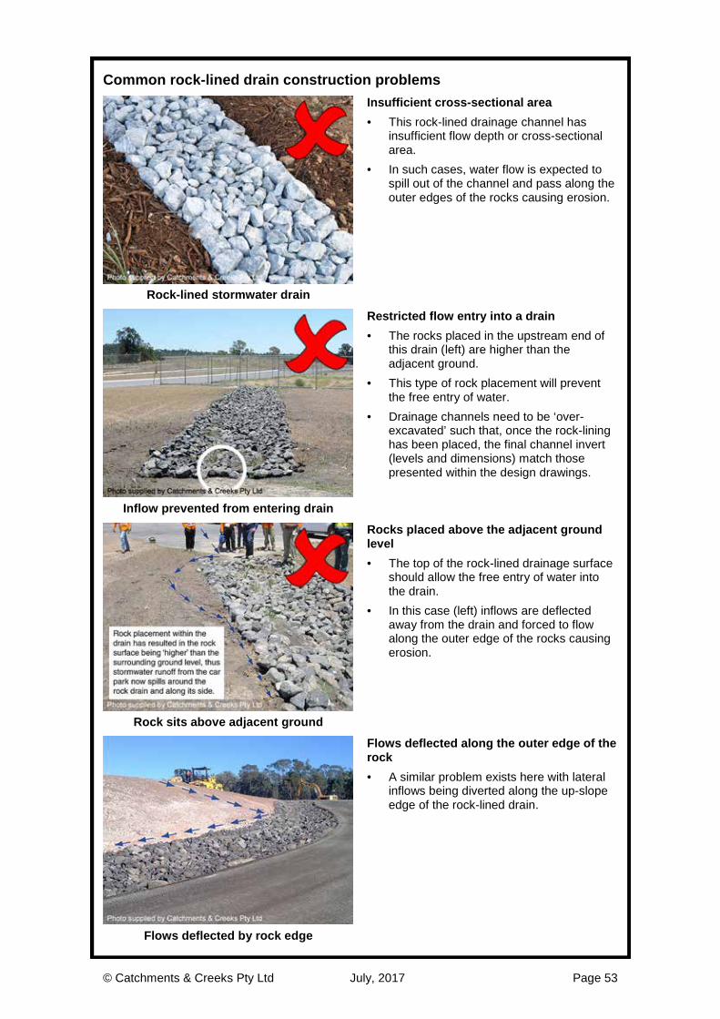
© Catchments & Creeks Pty Ltd July, 2017 Page 53
Common rock-lined drain construction problems
Insufficient cross-sectional area · This rock-lined drainage channel has
insufficient flow depth or cross-sectional area.
· In such cases, water flow is expected to spill out of the channel and pass along the outer edges of the rocks causing erosion.
Rock-lined stormwater drain
Restricted flow entry into a drain · The rocks placed in the upstream end of
this drain (left) are higher than the adjacent ground.
· This type of rock placement will prevent the free entry of water.
· Drainage channels need to be ‘over-excavated’ such that, once the rock-lining has been placed, the final channel invert (levels and dimensions) match those presented within the design drawings.
Inflow prevented from entering drain
Rocks placed above the adjacent ground level · The top of the rock-lined drainage surface
should allow the free entry of water into the drain.
· In this case (left) inflows are deflected away from the drain and forced to flow along the outer edge of the rocks causing erosion.
Rock sits above adjacent ground
Flows deflected along the outer edge of the rock · A similar problem exists here with lateral
inflows being diverted along the up-slope edge of the rock-lined drain.
Flows deflected by rock edge

© Catchments & Creeks Pty Ltd July, 2017 Page 54
Common rock-lined batter chute construction problems
Flow spills around rocks · A rock-lined drainage chute should not be
formed by simply filling an eroded gully with rocks such that the upper surface of the rocks sits above the adjacent ground level.
· In this case (left) soil erosion would be expected along each side of the recently placed rocks.
· Also, weeds will likely grow among the rocks, and these weeds will be difficult to manage.
Newly established rock chute
Flow spills around rocks · In the example shown left, the rocks have
not been recessed into the bank, but instead sit above the adjacent land surface.
· Inflows are likely to move to the edge of the rocks causing rilling down the side of the batter chute.
Rocks sitting above the soil profile
Rocks slip down smooth filter cloth · These rocks have been placed as a single
layer, on a steep slope, over filter cloth. · The filter cloth effectively acts as a low-
friction ‘slide’ and the rocks are now slowly slipping down the slope.
· If rocks need to be placed on steep slopes, then the rocks should be ‘keyed’ into the bank/soil.
· Keying can be done by ‘stair-stepping’ the bank prior to placing the filter cloth.
Rocks slipping down batter chute
Rock placed on dispersive or slaking soils · Rocks should not be placed directly onto
an untreated dispersive, sodic or slaking soil.
· If the subsoils are dispersive or slaking, then the batter chute should be over-excavated, then topped with a minimum 200 mm layer of non-dispersive (or treated) soil, then covered with filter cloth prior to placement of the amour rock.
Batter chute placed on a dispersive soil
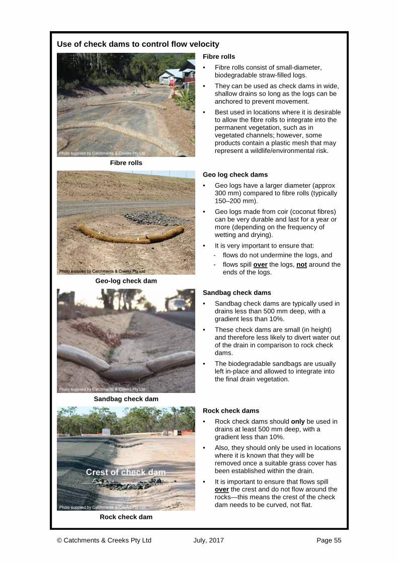
© Catchments & Creeks Pty Ltd July, 2017 Page 55
Use of check dams to control flow velocity
Fibre rolls · Fibre rolls consist of small-diameter,
biodegradable straw-filled logs. · They can be used as check dams in wide,
shallow drains so long as the logs can be anchored to prevent movement.
· Best used in locations where it is desirable to allow the fibre rolls to integrate into the permanent vegetation, such as in vegetated channels; however, some products contain a plastic mesh that may represent a wildlife/environmental risk.
Fibre rolls
Geo log check dams · Geo logs have a larger diameter (approx
300 mm) compared to fibre rolls (typically 150–200 mm).
· Geo logs made from coir (coconut fibres) can be very durable and last for a year or more (depending on the frequency of wetting and drying).
· It is very important to ensure that: - flows do not undermine the logs, and - flows spill over the logs, not around the
ends of the logs. Geo-log check dam
Sandbag check dams · Sandbag check dams are typically used in
drains less than 500 mm deep, with a gradient less than 10%.
· These check dams are small (in height) and therefore less likely to divert water out of the drain in comparison to rock check dams.
· The biodegradable sandbags are usually left in-place and allowed to integrate into the final drain vegetation.
Sandbag check dam
Rock check dams · Rock check dams should only be used in
drains at least 500 mm deep, with a gradient less than 10%.
· Also, they should only be used in locations where it is known that they will be removed once a suitable grass cover has been established within the drain.
· It is important to ensure that flows spill over the crest and do not flow around the rocks—this means the crest of the check dam needs to be curved, not flat.
Rock check dam

© Catchments & Creeks Pty Ltd July, 2017 Page 56
Common problems associated with the use of check dams
Check dams placed on dispersive soil · Dispersive soils become unstable if water
is allowed to pool on the soil. · Therefore, check dams should not be
used to control flow velocity if the surface soils are dispersive.
Rock check dam placed on dispersive soil
Check dams placed on steep slopes · Velocity control check dams provide
questionable benefit when placed on steep slopes.
Geo log placed on steep slope
Check dams staked in a manner that allows flow bypassing · Check dams must be installed in a manner
that allows water to pool up-slope of the check dam and then spill over, not around, the check dams.
Flow allowed to pass around geo logs
Failure to adequately anchor geo logs · A common problem experienced with geo-
log check dams is the failure to: - adequately anchor the logs onto the
soil, or - prevent water passing under the logs.
Flow allowed to pass under geo log
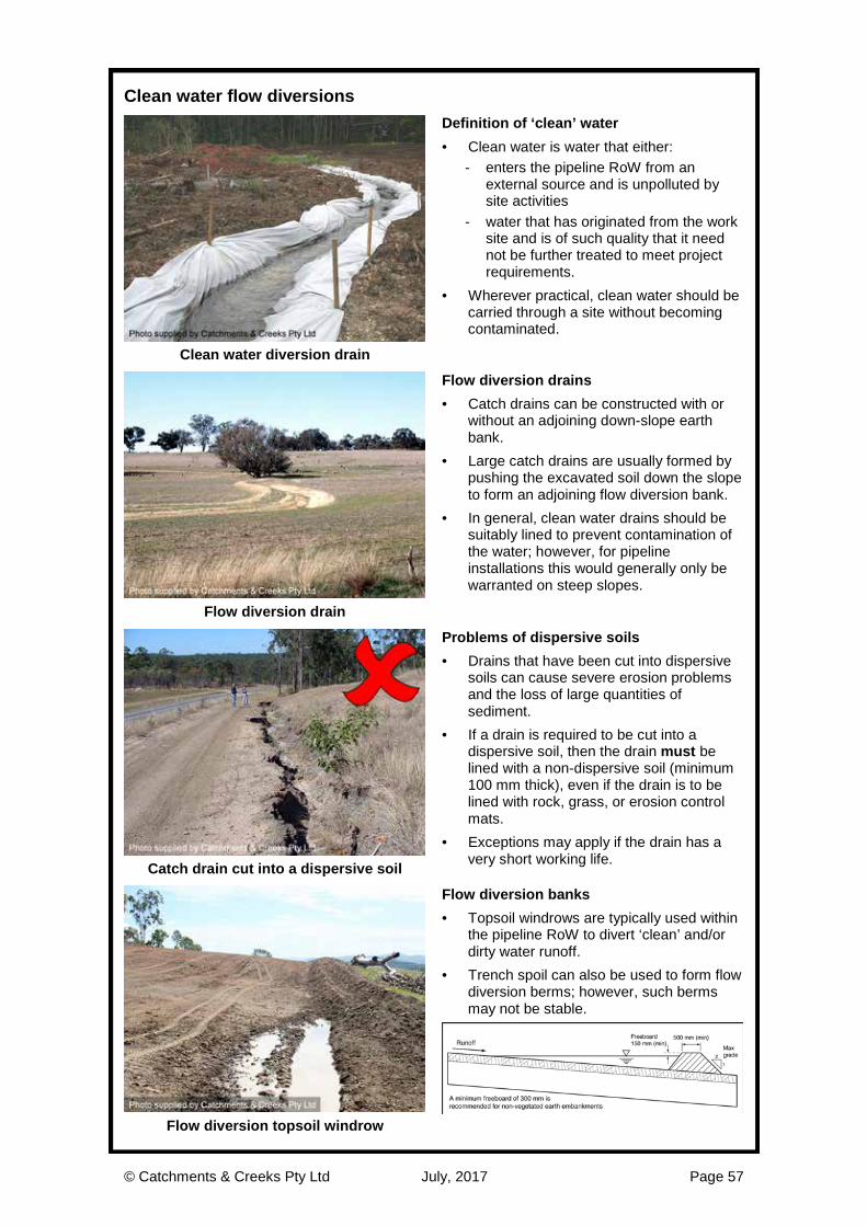
© Catchments & Creeks Pty Ltd July, 2017 Page 57
Clean water flow diversions
Definition of ‘clean’ water · Clean water is water that either:
- enters the pipeline RoW from an external source and is unpolluted by site activities
- water that has originated from the work site and is of such quality that it need not be further treated to meet project requirements.
· Wherever practical, clean water should be carried through a site without becoming contaminated.
Clean water diversion drain
Flow diversion drains · Catch drains can be constructed with or
without an adjoining down-slope earth bank.
· Large catch drains are usually formed by pushing the excavated soil down the slope to form an adjoining flow diversion bank.
· In general, clean water drains should be suitably lined to prevent contamination of the water; however, for pipeline installations this would generally only be warranted on steep slopes.
Flow diversion drain
Problems of dispersive soils · Drains that have been cut into dispersive
soils can cause severe erosion problems and the loss of large quantities of sediment.
· If a drain is required to be cut into a dispersive soil, then the drain must be lined with a non-dispersive soil (minimum 100 mm thick), even if the drain is to be lined with rock, grass, or erosion control mats.
· Exceptions may apply if the drain has a very short working life. Catch drain cut into a dispersive soil
Flow diversion banks · Topsoil windrows are typically used within
the pipeline RoW to divert ‘clean’ and/or dirty water runoff.
· Trench spoil can also be used to form flow diversion berms; however, such berms may not be stable.
Flow diversion topsoil windrow

© Catchments & Creeks Pty Ltd July, 2017 Page 58
Use of mulch berms for flow diversion
Beneficial use of mulch on site · Mulch berms can be used to divert either
clean run-on water, or site-generated dirty water.
· On pipeline projects, mulch berms are most commonly used for the protection of ancillary works, such as depots, material storage areas and equipment stations.
· Mulch berms can also be used as a form of sediment control (further discussion is provided later in this document).
Mulch berm
Make-up of hydraulically-stable mulch · The mulch should not be totally ‘clean’,
but should contain a small quantity of topsoil (generated from the mulching of tree roots) to help stabilise the mulch.
· The mulch must be produced through the use of tub grinders or the like, but not by chipping.
· The mulch needs to be very fibrous such that woody splinters achieve good interlocking and help the mulch to resistance movement.
Tub-grinded mulch
Velocity control adjacent to mulch berms · During minor storms, flow will generally
filter through the mulch; however, during major storms it is likely that flows will be diverted along the edge of the berm.
· If flow velocities adjacent the mulch berm are expected to be high during major storms, then Check Dams can be used to control these velocities.
· Rock check dams can also be used to increase the percentage of flow filtering though the berm.
Velocity control check dams
Outlet structures · Eventually the collected flow will need to
be discharged from the mulch berm. · ‘Clean’ water can simply be released from
the berm at regular intervals. · ‘Dirty’ water should be released only after
passing through an appropriate sediment trap.
· Filter cloth can be staked over the mulch berm at selected overflow points.
Flow release points

© Catchments & Creeks Pty Ltd July, 2017 Page 59
Managing drainage over the pipe trench
Cross bank drainage · Regular cross drainage berms should be
used to control the velocity (or discharge) of stormwater runoff passing along the pipeline RoW.
· Failure to adequately control drainage conditions can lead to severe erosion of the backfilled pipe trench.
· The importance of drainage controls increases with increasing rainfall potential and decreasing soil strength, especially if the soils are sandy, slaking or dispersive.
Storm damage to pipe trench
Cross drainage within pipeline RoW Dual uses of cross banks on RoW
Narrow width cross drainage berm (for low speed tracks)
Wide, low-gradient, cross drainage berm (for higher speed tracks)

© Catchments & Creeks Pty Ltd July, 2017 Page 60
Erosion Control Measures
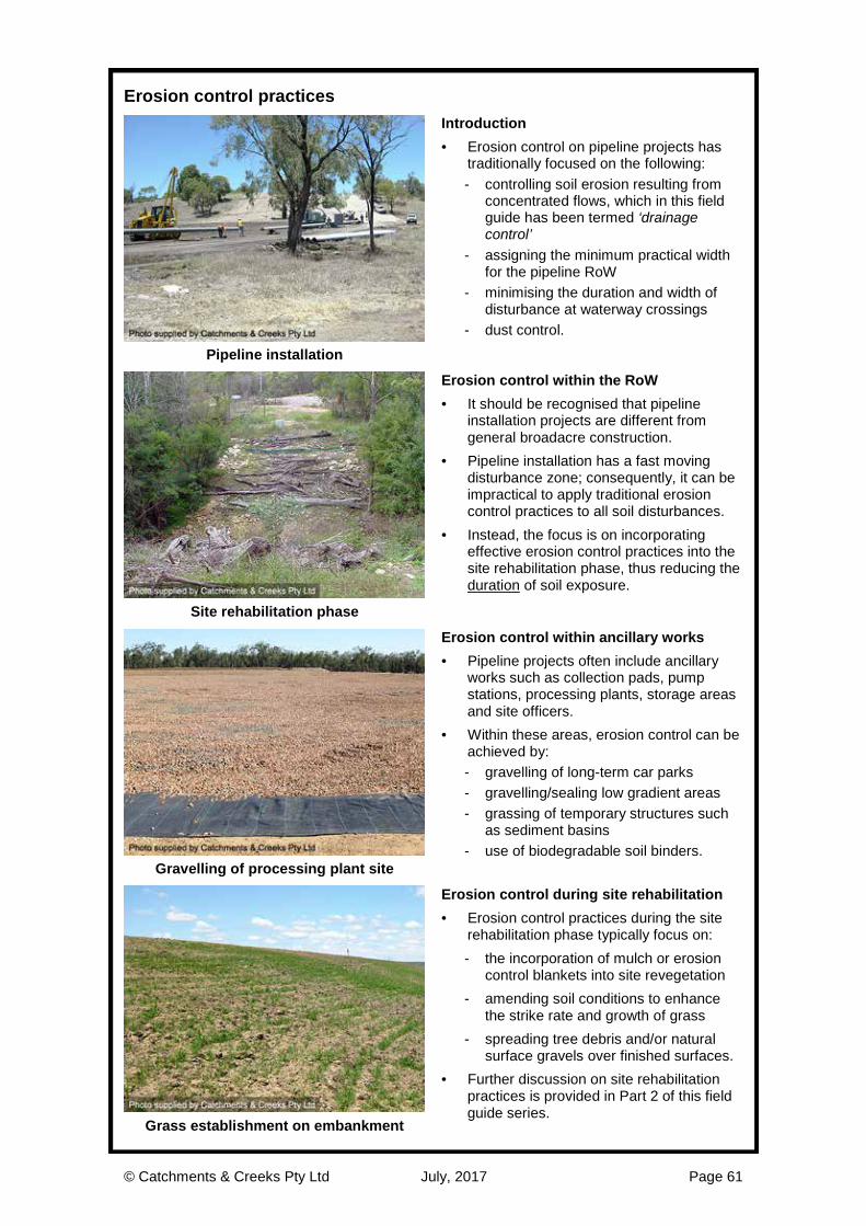
© Catchments & Creeks Pty Ltd July, 2017 Page 61
Erosion control practices
Introduction · Erosion control on pipeline projects has
traditionally focused on the following: - controlling soil erosion resulting from
concentrated flows, which in this field guide has been termed ‘drainage control’
- assigning the minimum practical width for the pipeline RoW
- minimising the duration and width of disturbance at waterway crossings
- dust control. Pipeline installation
Erosion control within the RoW · It should be recognised that pipeline
installation projects are different from general broadacre construction.
· Pipeline installation has a fast moving disturbance zone; consequently, it can be impractical to apply traditional erosion control practices to all soil disturbances.
· Instead, the focus is on incorporating effective erosion control practices into the site rehabilitation phase, thus reducing the duration of soil exposure.
Site rehabilitation phase
Erosion control within ancillary works · Pipeline projects often include ancillary
works such as collection pads, pump stations, processing plants, storage areas and site officers.
· Within these areas, erosion control can be achieved by: - gravelling of long-term car parks - gravelling/sealing low gradient areas - grassing of temporary structures such
as sediment basins - use of biodegradable soil binders.
Gravelling of processing plant site
Erosion control during site rehabilitation · Erosion control practices during the site
rehabilitation phase typically focus on: - the incorporation of mulch or erosion
control blankets into site revegetation - amending soil conditions to enhance
the strike rate and growth of grass - spreading tree debris and/or natural
surface gravels over finished surfaces. · Further discussion on site rehabilitation
practices is provided in Part 2 of this field guide series.
Grass establishment on embankment

© Catchments & Creeks Pty Ltd July, 2017 Page 62
Erosion control blankets
Biodegradable blankets · Organic-based blankets have low shear
strength, and thus a low allowable flow velocity.
· ‘Fine’ blankets are placed over seeded soil, while ‘thick’ blankets can be used to temporarily suppress weed growth.
· Blanket placement requires: - good soil conditioning - good surface preparation, and - intimate contact between the blanket
and the soil (i.e. no ‘tenting’). Jute blanket
Open mesh-type blankets · A ‘mesh’ is an open weave blanket made
from rope-like strands of hessian (jute) or coir (coconut fibre).
· It has a typical design life in dry environments of 12 to 24 months.
· In isolation, a mesh does not provide adequate protection against rainfall.
· Meshes can also be used to anchor loose mulch, such as straw.
· Once installed, a mesh can be sealed with a light spray of anionic bitumen emulsion.
Jute mesh
Temporary synthetic-reinforced blankets · Erosion control blankets with temporary
synthetic reinforcing have a low to medium shear strength.
· The plastic mesh can represent a threat to wildlife, potentially entrapping animals such as lizards, snakes and birds.
· These blankets typically have a design life less than 12 months.
· Synthetic-reinforced blankets generally have a limited use on pipeline projects.
Synthetic-reinforced blanket
Weed control blankets · Weed control features can be incorporated
into some erosion control blankets. · These weed control features are generally
long-term, but not permanent. · ‘Thick’ organic-based (jute) blankets and
woven synthetic blankets can also be used to suppress weed germination (short-term control only).
· These products also have a limited use on pipeline projects because weed control is best managed through appropriate soil management practices. Weed control blanket

© Catchments & Creeks Pty Ltd July, 2017 Page 63
Anchorage systems for erosion control blankets
Timber pegs and stakes · Short timber pegs can be used in a wide
variety of soils. · Stakes are typically used to anchor turf
placed in areas likely to experience high-velocity flows soon after turf placement.
· They can also be used to anchor erosion control blankets, especially if storms or strong winds are imminent.
Timber stakes
Metal pins or staples · Metal staples/pins are best used on firm to
hard (compacted) clayey soils. · Anchorage of these pins is partially by
friction, and partially through the rusting of the pins; therefore, conditions must exist that allow the pins to rust.
· Initially (i.e first few day/weeks) metal pins provide only marginal anchorage, and as such, the pinned blanket can be easily displaced by strong winds unless also anchored by rocks, sandbags or tree debris. Metal staples
Barbed plastic pins · Barbed plastic pins are best used in soft to
firm clayey soils, but generally not very sandy soils.
· They can be difficult to use if the soil is heavily compacted or natural (i.e. undisturbed soil).
· Care must be taken when these pins are used to anchor a ‘mesh’ to ensure the pin adequately captures or twists around the mesh.
Barbed plastic pins
Duck-billed soil anchor · Duck-billed soils anchors are best used in
soft sandy or silty soils, or any soil that has insufficient strength to hold other anchor types.
· These anchors can be used to anchor logs and fallen trees, which in-turn can be used to anchor erosion control blankets and mats on the banks of some waterways.
Duck-billed soil anchor

© Catchments & Creeks Pty Ltd July, 2017 Page 64
Common problems experienced with erosion control blankets
Poor anchorage of blankets · Erosion control blankets are normally
anchored with metal staples, or barbed plastic pegs.
· Blankets anchored solely with metal staples are susceptible to disturbance by strong winds, especially if the soil is soft to firm, and the staples have not rusted.
· Additional anchorage can be provided by tree debris and timber stakes/pegs.
Blankets displaced by winds
Blankets placed on dispersive or slaking soil · Erosion control blankets are not the
solution to all soil erosion problems. · Dispersive and slaking soils require
appropriate amelioration and/or sealing with topsoil prior to the placement of blankets or the seeding of the soil.
· Slaking soils (left) are likely to require barbed pins or timber pegs in order to secure the blankets.
Inappropriate anchorage pegs
Inappropriate anchorage systems · It can be very difficult to anchor blankets
onto a hard, compacted, or natural soil, especially some iron-rich clayey soils.
· Lateral thinking can often provide good outcomes, and circumstances may exist where timber screws could be used to anchor a blanket onto a hard soil, but: - if the soil is that hard, then the grass
seeding will likely fail, and - if the soil is dispersive, then just
watering the grass seed would likely cause the anchors to fail. Wood screws used to anchor a blanket
Blankets and mats overlapped against the direction of flow · Erosion control ‘blankets’ (meant for areas
subject to sheet flow) and erosion control ‘mats’ (meant for areas subject to concentrated flow) must overlap in the direction of flow (i.e. upper over lower).
· The direction of flow may be determined by: - the direction of overland sheet flow,
and/or - the direction of channel flow.
Mats overlapped in wrong direction

© Catchments & Creeks Pty Ltd July, 2017 Page 65
Gravelling
Gravelling · The term ‘gravel’ has several meanings in
engineering; however, in this case the term refers to crushed rock with sizes varying from dust up to the nominated rock size (but less than 75 mm).
· The term ‘aggregate’ refers to crushed rock or river stones of near uniform size.
· A surface layer of gravel or aggregate can be used to control raindrop impact across areas such as the site office, depot, pipe storage areas, temporary car parks, and access roads.
Gravelled depot and storage area
Geotextile underlay · Gravel is typically placed directly on the
soil surface; however, this can result in the eventual loss of the gravel into the soil profile.
· Gravel can also be placed over a geotextile underlay to increase the durability of the gravelled surface.
· Woven fabric underlays (left) can be more durable than non-woven filter cloth.
Placement of gravel over geotextile
Gravel roads and access track · The gravelling of active construction
access roads and tracks can provide questionable benefits because, under heavy construction traffic, the gravel can quickly integrate into the underlying soil, unless a geotextile underlay is used.
· Gravelling normally provides greatest benefits for the stabilisation of long-term maintenance access roads after the construction phase is finished.
· The cost/benefit should be assessed on a site-by-site basis. Gravelled access road
Arid and semi-arid areas · In arid and semi-arid areas, natural
surface gravels and sands can be an important aspect of the soil’s natural erosion control.
· These gravels should be stripped and stockpiled separately from the topsoil; and should be returned to the soil surface during site rehabilitation.
Natural surface gravels
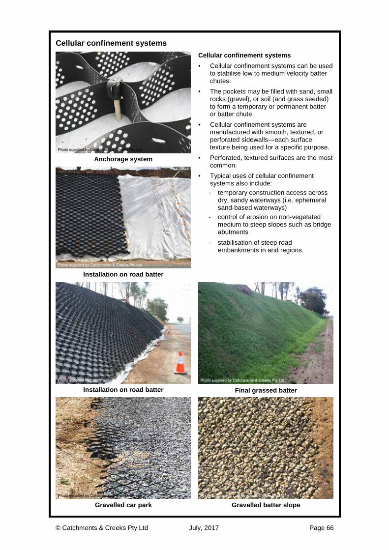
© Catchments & Creeks Pty Ltd July, 2017 Page 66
Cellular confinement systems
Cellular confinement systems · Cellular confinement systems can be used
to stabilise low to medium velocity batter chutes.
· The pockets may be filled with sand, small rocks (gravel), or soil (and grass seeded) to form a temporary or permanent batter or batter chute.
· Cellular confinement systems are manufactured with smooth, textured, or perforated sidewalls—each surface texture being used for a specific purpose.
· Perforated, textured surfaces are the most common.
· Typical uses of cellular confinement systems also include: - temporary construction access across
dry, sandy waterways (i.e. ephemeral sand-based waterways)
- control of erosion on non-vegetated medium to steep slopes such as bridge abutments
- stabilisation of steep road embankments in arid regions.
Anchorage system
Installation on road batter
Installation on road batter Final grassed batter
Gravelled car park Gravelled batter slope
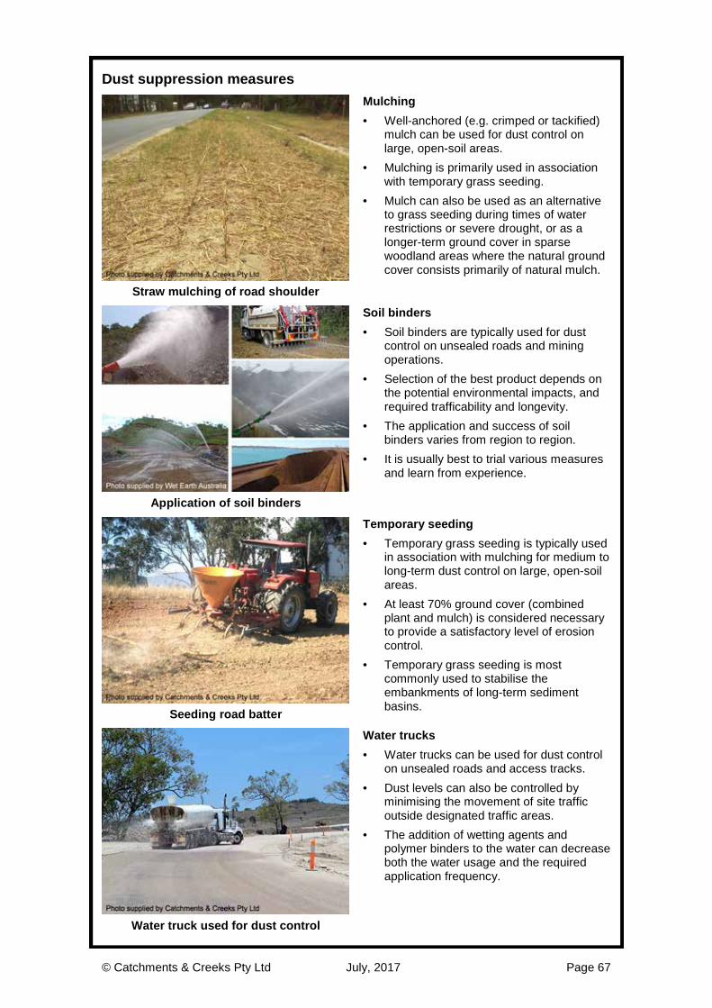
© Catchments & Creeks Pty Ltd July, 2017 Page 67
Dust suppression measures
Mulching · Well-anchored (e.g. crimped or tackified)
mulch can be used for dust control on large, open-soil areas.
· Mulching is primarily used in association with temporary grass seeding.
· Mulch can also be used as an alternative to grass seeding during times of water restrictions or severe drought, or as a longer-term ground cover in sparse woodland areas where the natural ground cover consists primarily of natural mulch.
Straw mulching of road shoulder
Soil binders · Soil binders are typically used for dust
control on unsealed roads and mining operations.
· Selection of the best product depends on the potential environmental impacts, and required trafficability and longevity.
· The application and success of soil binders varies from region to region.
· It is usually best to trial various measures and learn from experience.
Application of soil binders
Temporary seeding · Temporary grass seeding is typically used
in association with mulching for medium to long-term dust control on large, open-soil areas.
· At least 70% ground cover (combined plant and mulch) is considered necessary to provide a satisfactory level of erosion control.
· Temporary grass seeding is most commonly used to stabilise the embankments of long-term sediment basins. Seeding road batter
Water trucks · Water trucks can be used for dust control
on unsealed roads and access tracks. · Dust levels can also be controlled by
minimising the movement of site traffic outside designated traffic areas.
· The addition of wetting agents and polymer binders to the water can decrease both the water usage and the required application frequency.
Water truck used for dust control

© Catchments & Creeks Pty Ltd July, 2017 Page 68
Introduction to Sediment Control Practices
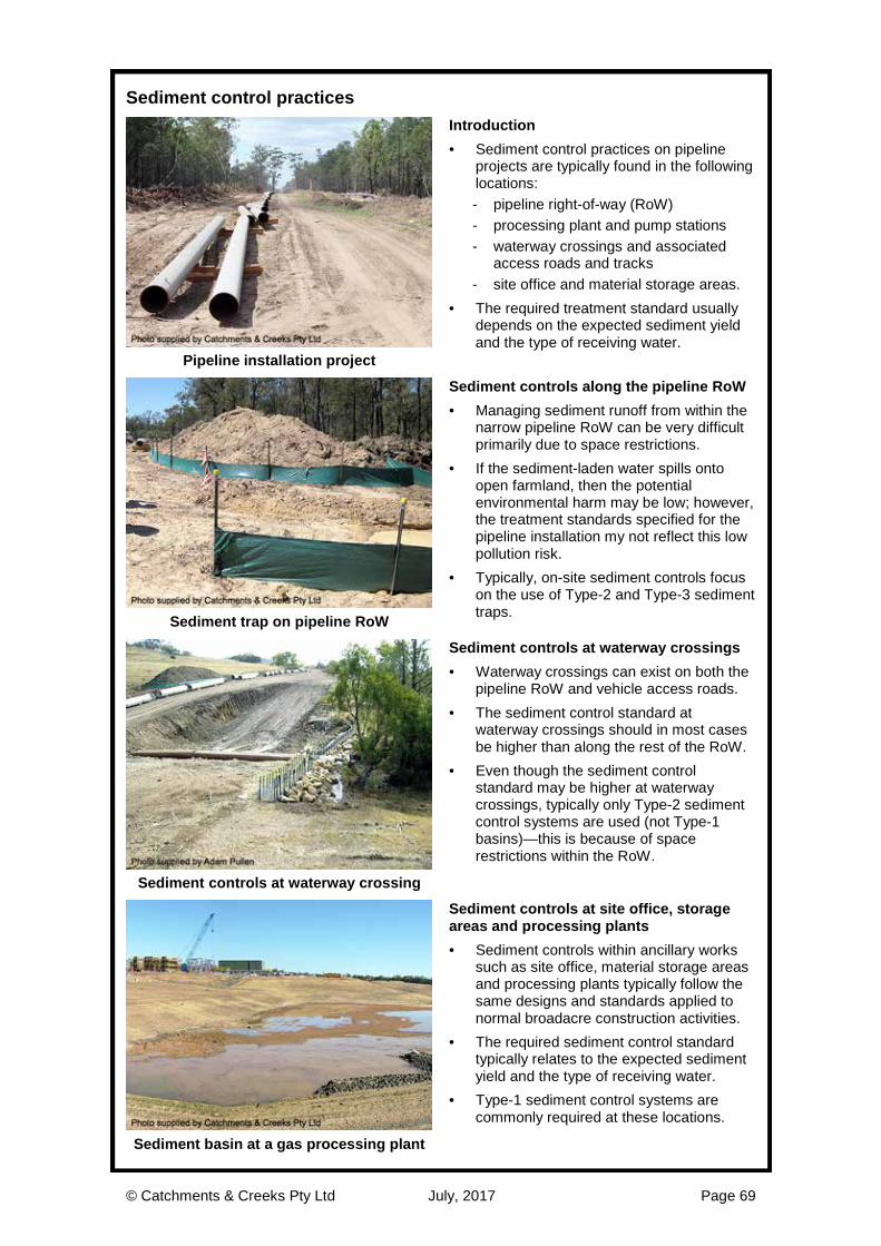
© Catchments & Creeks Pty Ltd July, 2017 Page 69
Sediment control practices
Introduction · Sediment control practices on pipeline
projects are typically found in the following locations: - pipeline right-of-way (RoW) - processing plant and pump stations - waterway crossings and associated
access roads and tracks - site office and material storage areas.
· The required treatment standard usually depends on the expected sediment yield and the type of receiving water.
Pipeline installation project
Sediment controls along the pipeline RoW · Managing sediment runoff from within the
narrow pipeline RoW can be very difficult primarily due to space restrictions.
· If the sediment-laden water spills onto open farmland, then the potential environmental harm may be low; however, the treatment standards specified for the pipeline installation my not reflect this low pollution risk.
· Typically, on-site sediment controls focus on the use of Type-2 and Type-3 sediment traps. Sediment trap on pipeline RoW
Sediment controls at waterway crossings · Waterway crossings can exist on both the
pipeline RoW and vehicle access roads. · The sediment control standard at
waterway crossings should in most cases be higher than along the rest of the RoW.
· Even though the sediment control standard may be higher at waterway crossings, typically only Type-2 sediment control systems are used (not Type-1 basins)—this is because of space restrictions within the RoW.
Sediment controls at waterway crossing
Sediment controls at site office, storage areas and processing plants · Sediment controls within ancillary works
such as site office, material storage areas and processing plants typically follow the same designs and standards applied to normal broadacre construction activities.
· The required sediment control standard typically relates to the expected sediment yield and the type of receiving water.
· Type-1 sediment control systems are commonly required at these locations.
Sediment basin at a gas processing plant
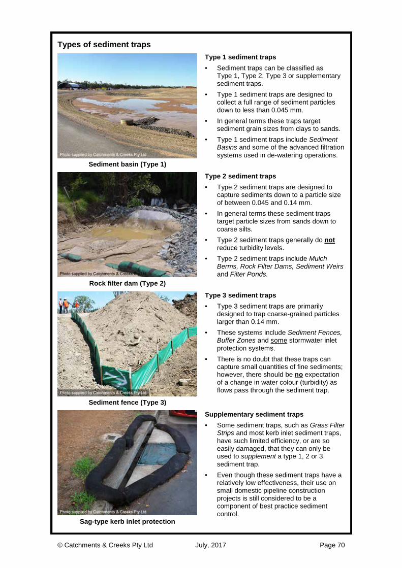
© Catchments & Creeks Pty Ltd July, 2017 Page 70
Types of sediment traps
Type 1 sediment traps · Sediment traps can be classified as
Type 1, Type 2, Type 3 or supplementary sediment traps.
· Type 1 sediment traps are designed to collect a full range of sediment particles down to less than 0.045 mm.
· In general terms these traps target sediment grain sizes from clays to sands.
· Type 1 sediment traps include Sediment Basins and some of the advanced filtration systems used in de-watering operations.
Sediment basin (Type 1)
Type 2 sediment traps · Type 2 sediment traps are designed to
capture sediments down to a particle size of between 0.045 and 0.14 mm.
· In general terms these sediment traps target particle sizes from sands down to coarse silts.
· Type 2 sediment traps generally do not reduce turbidity levels.
· Type 2 sediment traps include Mulch Berms, Rock Filter Dams, Sediment Weirs and Filter Ponds.
Rock filter dam (Type 2)
Type 3 sediment traps · Type 3 sediment traps are primarily
designed to trap coarse-grained particles larger than 0.14 mm.
· These systems include Sediment Fences, Buffer Zones and some stormwater inlet protection systems.
· There is no doubt that these traps can capture small quantities of fine sediments; however, there should be no expectation of a change in water colour (turbidity) as flows pass through the sediment trap.
Sediment fence (Type 3)
Supplementary sediment traps · Some sediment traps, such as Grass Filter
Strips and most kerb inlet sediment traps, have such limited efficiency, or are so easily damaged, that they can only be used to supplement a type 1, 2 or 3 sediment trap.
· Even though these sediment traps have a relatively low effectiveness, their use on small domestic pipeline construction projects is still considered to be a component of best practice sediment control.
Sag-type kerb inlet protection

© Catchments & Creeks Pty Ltd July, 2017 Page 71
Types of sediment traps
Mechanics of sediment traps · The mechanics of sediment trapping can
generally be categorised into the following groups: - ponding traps that primarily utilise
gravity-induced particle settlement - ponding traps that utilise a filtration
system for the treatment of low-flows - extended detention settling basins - geotextile filters - sand and aggregate filters - compost filters.
Topsoil windrow sed-trap with filter tube
Type 3 sediment traps · Most Type 3 sediment traps are designed
to slow the passage of water to such a degree that pooling occurs up-slope of the trap.
· It is this pooling of water that allows gravity-induced settlement of the coarser grained particles (i.e. sands).
· A sediment fence is not a ‘filter’. · A sediment fence is just a porous dam that
encourages sediment-laden water to pool up-slope of the fence.
Type 3 treatment system
Type 2 sediment traps · The key components of a Type 2 sediment
trap are a ‘settling pond’ followed by a ‘coarse-particle filter’.
· Just like a sediment fence, a Type 2 sediment trap is designed to encourage the pooling of water up-slope of the trap.
· Gravity-induced settlement is then supplemented by either a geotextile, aggregate or compost filter.
· A compost filter is simply a compost berm through which water can percolate.
Type 2 treatment system
Type 1 sediment traps · Type 1 sediment traps utilise either:
- extended detention to encourage the settlement of clay-sized particles; or
- super-fine, high-pressure filters. · Sediment basins operate as either:
- continuous-flow systems; or - plug-flow system.
· High-pressure filters are normally only used during specialist de-watering operations, typically only used in urban areas.
Type 1 treatment system

© Catchments & Creeks Pty Ltd July, 2017 Page 72
Critical features of sediment traps
Critical features of a sediment trap · Most sediment traps incorporate the
following critical features: - the ability to pool water - adequate retention time to allow the
settlement of suspended particles - the capacity to collect and retain a
specific volume of settled sediment - adequate hydraulic capacity prior to the
commencement of flow bypassing - limits on the maximum depth of pooling
in areas where public safety is a concern. Rock filter dam with aggregate filter
Critical features of the settling pond · The presence of a settling pond means
the focus is on gravity-induced settlement. · In a continuous-flow system, the critical
design parameter is the surface area of the pond (as in the design of a Type-A, B & C sediment basin).
· In a plug-flow system, the critical design parameter is the volume of the settling pond (as in the design of a Type D sediment basin).
‘Wet’ type sediment basin
Ability to capture and hold sediment · A sediment trap should not just divert
sediment-laden water from one location to another.
· When constructing a sediment trap, ask yourself: - Will the device cause a safety problem? - Where is the water going to flow? - Where is the sediment going to settle? - How will the trapped sediment be
collected and removed?
Sediment fence fails to capture sediment
Caution regarding the placement of sediment trap on steep slopes · On steep slopes, say steeper than 10%
(1 in 10), the focus should firstly be on controlling soil erosion, and secondly on controlling the flow of water down the slope.
· Wherever practical, the trapping of sediment should occur at the base of the slope, or at a location well away from the slope where it is safe and convenient to temporarily pond water (i.e. away from the pipeline trench and access track).
Stormwater runoff bypasses sediment trap

© Catchments & Creeks Pty Ltd July, 2017 Page 73
Critical features of sediment traps
Operation of sediment traps · It is critically important to ensure that the
sediment-laden water flows through the settling pond; not around its edges.
· Only upon flowing through the pond will the flow velocity slow allowing settlement.
· The example below shows one solution using a minimum 300 mm high spill-through weir; however, an alternative option would be to extend the ‘arms’ of the U-shaped trap up the slope a sufficient distance to prevent flow bypassing.
Sediment trap with no overflow weir
Inappropriate sediment trap set-up
Once full, the sediment trap allows sediment-laden flow to bypass the trap
Sediment-laden water passes through the settling pond allowing sedimentation

© Catchments & Creeks Pty Ltd July, 2017 Page 74
Types of sediment filters
Types of filters · Many sediment traps incorporate some
type of filtration system. · The filter media may consist of straw,
sand, aggregate, geotextile or compost. · Straw-based filters are very inefficient and
their primary purpose is usually to encourage ponding rather than filtration.
· Most sand-based filters are also very inefficient due to their low through-flow discharge.
Sand-filled filter sock
Aggregate filters · The most important thing to know about
aggregate filters is that they rely on the effects of partial sediment blockage to activate (start) the filtration process.
· A filter formed from clean aggregate does not provide much ‘filtration’; at best it simply helps to slow water flow to encourage up-slope ponding.
· Aggregate filters are best used in sandy or silty soils (i.e. soils with a clay content less than, say 20%).
Rock filter dam with aggregate filter
Geotextile filters · Geotextile filters are made from non-
woven fabrics (woven fabrics should not be used).
· Most geotextile filters initially have a high flow rate, but sediment blockage can eventually reduce this to zero.
· The use of geotextile filters is preferred if the capture of fine-grained sediments is required.
· Geotextile filters rarely reduce turbidity levels, thus the water remains ‘brown’.
Filter tube attached to an embankment
Compost filters · Compost filters use both filtration and
adsorption processes to clean the through-flow.
· Thus compost filters can adsorb minor amounts of dissolved and fine particulate matter such as metals.
· These filters are considered to perform better than most sand, aggregate or geotextile filters, provided the filter remains undamaged and outflows are not allowed to bypass the filter.
Compost-filled filter sock

© Catchments & Creeks Pty Ltd July, 2017 Page 75
Use of geotextiles in sediment control
Use of geotextiles in sediment control · Geotextiles can be used for a number of
purposes, including: - slowing water flow to encourage
pooling and sedimentation - the filtration of flows - geotechnical engineering.
· Composite fabrics are sometimes used when it is desirable to perform more than one of the above tasks.
· Composite ESC fabrics are not always commercially available.
Composite sediment fence fabric
Woven fabrics · The primary purpose of a woven fabric is
to slow the passage of water—these fabrics are not used for filtration.
· In most cases, the fabric is made from thin strips of impervious material; thus water can only weep through small gaps where the fabric strips overlap.
· These fabrics are normally carbon stabilised (often producing the black colour) to reduce UV damage and to extent their working life.
Woven sediment fence fabric
Non-woven fabrics · Non-woven fabrics are primarily used for
filtration and geotechnical engineering. · Most non-woven fabrics are not UV
stabilised, thus they have a limited working life if exposed to direct sunlight.
· Filter cloth is the most common non-woven fabric found on construction sites.
· In Australia, filter cloth is commonly graded using the ‘bidim’ grading of A12 (thin) to A64 (thickest).
Non-woven filter cloth
Hessian fabric · Hessian fabrics fall outside the normal
rules because they are woven fabrics, but unlike most woven fabrics, they encourage filtration.
· Hessian fabrics can be used to form erosion control blankets as well as hessian sandbags.
· Hessian sandbags can be filled with sand or aggregate to form a filter berm.
Filter sock

© Catchments & Creeks Pty Ltd July, 2017 Page 76
Sediment control on small domestic pipeline projects
Domestic pipeline installations · Erosion and Sediment Control practices
are equally required on small domestic pipeline installations as for large rural projects.
· Sediment traps typically consist of: - sediment fences - roadside kerb inlet sediment traps - de-watering sediment filters.
Domestic pipe installation
Management of stockpiles · Excavated material should not be
stockpiled in locations where it could cause harm, or be washed into a gutter, drain or water body.
· Wherever practical, avoid stockpiling earth on a road pavement, within an overland flow path, or adjacent to stream banks.
· Substantial sediment controls may not be required if the stockpile has a short life span (< 24 hours) or when rain is unlikely to occur.
Managing stockpiles
Sediment control during maintenance work · Sediment controls are often required
during the maintenance of domestic pipelines.
· The failure of a pressure pipe can cause large sediment flows to enter residential streets, which will need to be appropriately collected and removed.
· Typically, roadside and kerb inlet sediment traps are the only practical means of controlling sediment flows during pipe maintenance and site clean-up.
Repairing a pressure pipe failure
De-watering sediment controls · Pipeline installation and maintenance
activities often involve the de-watering of trenches, during which appropriate sediment controls must be employed.
· It is generally considered inappropriate to limit sediment control practices to just pumping onto the grassed verge.
· Grass filter are generally ineffective once the underlying soil becomes saturated.
· Discussion on various de-watering sediment control practices is provided later in this document. Pipe trench de-watering

© Catchments & Creeks Pty Ltd July, 2017 Page 77
Kerb inlet sediment traps
Sag inlet sediment traps · ‘Sag’ inlets exist at low points along a road
profile. · A sag inlet sediment trap must allow water
to pool on the road adjacent to the inlet in order to achieve particle settlement.
· Sag inlet sediment traps should not block the inlet opening, but should be set back from the inlet (normally using spacers) to allow the drain to function, especially during periods of heavy rainfall.
Sag inlet sediment trap
On-grade inlet sediment traps · An on-grade sediment trap consists of one
or more U-shaped sandbag traps constructed up-slope of the inlet.
· Typically more than one such sediment trap is required up-slope of the inlet.
On-grade kerb inlet sediment trap
Gully bag sediment traps · Gully bag sediment traps (i.e. special filter
bags installed below the inlet grate) can be used on both ‘sag’ and ‘on-grade’ kerb inlets.
· These types of gully traps include the flexible filter bags (left) and solid filter boxes lined with filter cloth.
Gully bag sediment trap
Safety issues · Public safety must always take priority. · If the installation of the sediment trap is
likely to result in an unmanageable and/or unacceptable safety risk, then an alternative sediment trap must be used, such as a gully bag.
· Roadside sediment traps can also be damaged by road traffic; thus operators must exercise extreme care and caution when placing these devices on public roadways.
Flooded road surface
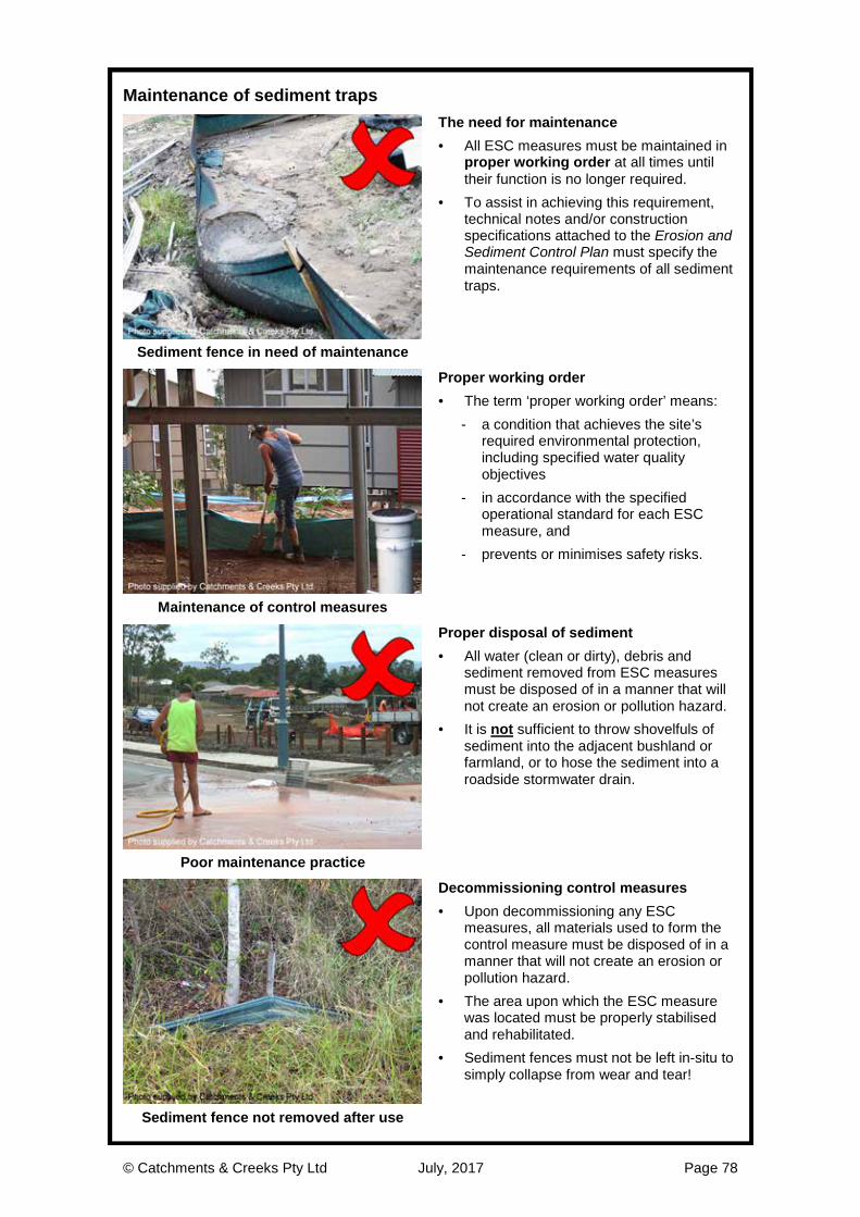
© Catchments & Creeks Pty Ltd July, 2017 Page 78
Maintenance of sediment traps
The need for maintenance · All ESC measures must be maintained in
proper working order at all times until their function is no longer required.
· To assist in achieving this requirement, technical notes and/or construction specifications attached to the Erosion and Sediment Control Plan must specify the maintenance requirements of all sediment traps.
Sediment fence in need of maintenance
Proper working order · The term ‘proper working order’ means:
- a condition that achieves the site’s required environmental protection, including specified water quality objectives
- in accordance with the specified operational standard for each ESC measure, and
- prevents or minimises safety risks.
Maintenance of control measures
Proper disposal of sediment · All water (clean or dirty), debris and
sediment removed from ESC measures must be disposed of in a manner that will not create an erosion or pollution hazard.
· It is not sufficient to throw shovelfuls of sediment into the adjacent bushland or farmland, or to hose the sediment into a roadside stormwater drain.
Poor maintenance practice
Decommissioning control measures · Upon decommissioning any ESC
measures, all materials used to form the control measure must be disposed of in a manner that will not create an erosion or pollution hazard.
· The area upon which the ESC measure was located must be properly stabilised and rehabilitated.
· Sediment fences must not be left in-situ to simply collapse from wear and tear!
Sediment fence not removed after use

© Catchments & Creeks Pty Ltd July, 2017 Page 79
Sediment Control Techniques

© Catchments & Creeks Pty Ltd July, 2017 Page 80
Mulch berm sediment traps
Mulch berms · A Type 2 sediment trap. · Mulch and compost berms (the latter
being less common on pipeline projects) can act as both drainage control systems and sediment control systems.
· In general, mulch berms perform better than a traditional sediment fence (being only a type 3 system) but only if the berm remains undamaged by construction traffic, and if the berm is not damaged by excess stormwater runoff.
Mulch berm
Make-up of hydraulically-stable mulch · The mulch should not be totally ‘clean’,
but should contain a small quantity of topsoil (generated from the mulching of tree roots) to help stabilise the mulch.
· The mulch must be produced through the use of tub grinders or the like, but not by chipping.
· The mulch needs to be very fibrous such that woody splinters achieve good interlocking and help the mulch to resistance movement.
Tub-grinded mulch
Velocity control adjacent to mulch berms · During minor storms, flow will generally
filter through the mulch; however, during major storms it is likely that flows will be diverted along the edge of the berm.
· If flow velocities adjacent the mulch berm are expected to be high during major storms, then Check Dams can be used to control these velocities.
· Rock check dams can also be used to increase the percentage of flow passing though the berm.
Velocity control check dams
Outlet structures · During the wet season, overflow weirs
should be formed at low points along the mulch berm to prevent the hydraulic failure of the berm during major storms.
· Rock Filter Dams, Sediment Sumps or Sediment Weirs can also be integrated into low points along the mulch berm to enhance the treatment of the discharged water.
Flow release points

© Catchments & Creeks Pty Ltd July, 2017 Page 81
Sediment sumps
Sediment sumps · Unlike many urban projects, rural pipeline
installations often provide the opportunity to use simple Sediment Sumps as sediment traps.
· Sediment sumps can come in several forms, but the simplest is just an excavated pit at the end of a minor drainage diversion.
Excavated sediment sump
Operation of sediment sumps · As flows pass over the sediment sump,
flow velocities slow, allowing coarse sediments to settle out.
· Site inspections must check that: - the sediment sump does not represent
a safety issue, and - the side walls of the excavated pit are
not subject to scour or slumping.
Excavated sediment sump
Enhanced treatment · The degree of sediment capture can be
enhanced through the incorporation of a Type 2 sediment filter into the outlet of the sediment sump.
· Suitable Type 2 filters include: - Filter Tube Dams, and - Rock Filter Dams lined with filter cloth.
· Rock filter dams with aggregate filters should not be used as outlet structures because the aggregate usually fails to function properly as a sediment filter.
Excavated sediment sump
Complications caused by erodible soils · Sediment sumps cannot be formed in
highly erodible soils such as: - dispersive (sodic) soils - slaking soils, and - non-cohesive sandy soils.
· In the case of slaking or non-cohesive sandy soils, geotextile filter cloth can sometimes be used to stabilise inflow points.
Sediment sump formed in dispersive soil

© Catchments & Creeks Pty Ltd July, 2017 Page 82
Rock filter dams
Use of rock filter dams · A Type 2 sediment trap. · Rock filter dams can be used as sediment
traps connected to the outlets of mulch berms and topsoil windrows.
· Rock filter dams wrapped in filter cloth can also be used as ‘instream’ sediment traps when pipelines cross constructed drainage channels.
Rock filter dam
Rock filter dam with geotextile filter · Rock filter dams can be used on pipeline
RoWs in locations where it is impractical to construct a formal Sediment Basin.
· The critical design parameter is the surface area of the settling pond, which must be maximised.
· The use of filter cloth as the primary ‘filter’ is the preferred construction technique if the capture of fine-grained sediment is considered critical
Rock filter dam - geotextile filter
Rock filter dam with aggregate filer · Aggregate-based filtration systems are
best used in sandy soil areas. · Aggregate filters generally rely on the
effects of partial sediment blockage to achieve their optimum filtration performance.
· Rock filter dams with aggregate filters are generally not suitable for use on pipeline projects because their working life is usually too short to allow the aggregate filter to develop its optimum filtration properties. Rock filter dam - aggregate filer
Sediment collection pits · Caution; placing an excavated pit
immediately up-slope of an ‘aggregate filter’ may reduce the filtration performance of a rock filter dam.
· Aggregate filters rely upon the partial blockage of the aggregate with coarse and fine sediments in order to commence the ‘filtration’ process—an excavated sediment collection pit therefore reduces the essential partial sediment-blockage of the aggregate filter.
Excavated sediment trap

© Catchments & Creeks Pty Ltd July, 2017 Page 83
Sediment weirs
Use of sediment weirs · A Type 2 sediment trap. · Sediment weirs are used where space is
limited (i.e. when space is not available for the construction of a Rock Filter Dam).
· Sediment weirs can be very durable in conditions of high flow rates where the sediment trap may be subjected to regular over-topping flows.
· They can also be used as a primary outlet structure on a Type 2 Sediment Basin (as is the case shown left).
Sediment weir (field inlet protection)
Use as in-channel sediment traps · Sediment weirs can also be used as
temporary in-channel sediment traps when pipelines cross drainage lines and minor waterways that are likely to experience only minor dry weather flows (refer to Part-2 of the field guide).
· Filter Tubes can be incorporated into the sediment weir to increase the treatable flow rate.
· The critical design parameter is the ‘surface area’ of the settling pond, which must be maximised. Sediment weir
Sediment weir with aggregate filter Sediment weir with filter tube incorporated
into the weir
Construction difficulties · Sediment weirs can be used at pipeline
crossings of rural drainage lines; however, the time and labour costs of their installation makes them of questionable value in most locations along a pipeline RoW.
Construction of a sediment weir
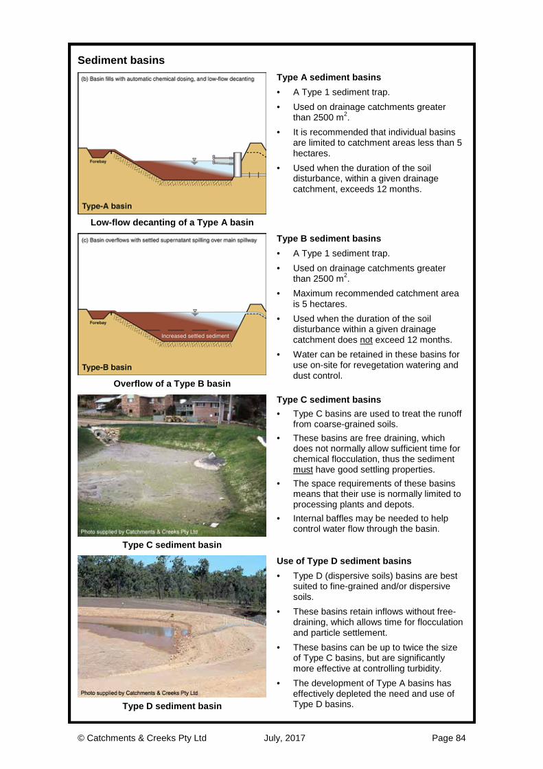
© Catchments & Creeks Pty Ltd July, 2017 Page 84
Sediment basins
Type A sediment basins · A Type 1 sediment trap. · Used on drainage catchments greater
than 2500 m2. · It is recommended that individual basins
are limited to catchment areas less than 5 hectares.
· Used when the duration of the soil disturbance, within a given drainage catchment, exceeds 12 months.
Low-flow decanting of a Type A basin
Type B sediment basins · A Type 1 sediment trap. · Used on drainage catchments greater
than 2500 m2. · Maximum recommended catchment area
is 5 hectares. · Used when the duration of the soil
disturbance within a given drainage catchment does not exceed 12 months.
· Water can be retained in these basins for use on-site for revegetation watering and dust control.
Overflow of a Type B basin
Type C sediment basins · Type C basins are used to treat the runoff
from coarse-grained soils. · These basins are free draining, which
does not normally allow sufficient time for chemical flocculation, thus the sediment must have good settling properties.
· The space requirements of these basins means that their use is normally limited to processing plants and depots.
· Internal baffles may be needed to help control water flow through the basin.
Type C sediment basin
Use of Type D sediment basins · Type D (dispersive soils) basins are best
suited to fine-grained and/or dispersive soils.
· These basins retain inflows without free-draining, which allows time for flocculation and particle settlement.
· These basins can be up to twice the size of Type C basins, but are significantly more effective at controlling turbidity.
· The development of Type A basins has effectively depleted the need and use of Type D basins. Type D sediment basin

© Catchments & Creeks Pty Ltd July, 2017 Page 85
Sediment basin spillways
Function of a basin spillway · All sediment basins that are not fully
recessed below natural ground level will require the construction of a formally designed spillway.
· The spillway must have a well-defined weir profile (cross-section) that fully contains the nominated peak discharge.
· A suitable energy dissipater will be required at the base of the spillway.
· Spillways are critical engineering structures that need to be designed by suitably qualified engineers. Spillway with well-defined weir profile
Preferred location of spillways · Ideally, the emergency spillway should be
constructed in virgin soil (i.e. adjacent to the fill embankment).
Spillway formed within virgin soil
Controlling leakage at spillway crest · For rock and rock mattress lined spillways,
it is important to control seepage flows through those rocks located near the crest of the spillway.
· Seepage control is required so that the settling pond can achieve its required maximum water level prior to flows discharging over the spillway.
· Concrete capping of the spillway crest may be required in order to prevent these seepage flows.
Flows can pass through the rock voids
Preferred crest profile · It is important to ensure that the spillway
crest has sufficient depth and width to fully contain the nominated design storm discharge.
· The spillway crest normally requires a greater depth, but equal width, to that of the downstream spillway chute.
· Photo (left) shows a spillway crest that has inadequate depth or flow profile, in fact the rock-lined crest sits ‘above’ the adjacent earth embankment crest!
Inappropriate spillway crest profile

© Catchments & Creeks Pty Ltd July, 2017 Page 86
Sediment basin spillways
Hydraulic design · Basin spillways are hydraulic structures
that need to be designed for a specified design storm.
· The hydraulic design of spillways can be broken down into three components: - design of the spillway inlet using an
appropriate weir equation - sizing rock for the face of the chute
based on Manning’s equation velocity - sizing rock for the energy dissipater.
Dam spillway hydraulics
Design of spillway crest · Flow conditions at the spillway crest may
be determined using an appropriate weir equation.
· It is important to ensure that the required maximum potential water level within the basin can be fully contained by the basin’s embankments.
· The sealing of the spillway crest is often necessary to maximise basin storage and prevent leakage through the rock voids.
Sealing of spillway crest
Design of spillway chute · Determination of rock size on the spillway
is based on either the maximum unit flow rate (q, m3/s/m) or the maximum flow velocity (V, m/s) down the spillway.
· The upstream portion of the spillway’s inflow channel can be curved (i.e. that section upstream of the spillway crest).
· Once the spillway begins to descend down the embankment (i.e. where the flow is supercritical) the spillway chute must be straight.
Dam spillway cut into virgin soil
Design of energy dissipater · A suitable energy dissipater or outlet
structure is required at the base of the spillway.
· The design of the energy dissipater must be assessed on a case-by-case basis.
· Energy dissipation ponds often need to be recessed below the downstream discharge channel in order to achieve ideal energy dissipation—this may mean that water is retained within these ponds for some time after an overtopping event.
Energy dissipation pond

© Catchments & Creeks Pty Ltd July, 2017 Page 87
Common spillway design and construction problems
Inadequate spillway crest profile · A poorly defined spillway crest profile (e.g.
insufficient cross-sectional width or depth) can result in flows bypassing the spillway.
· In such cases (left) damage to the earth embankment is likely to occur.
Poorly defined spillway crest
Insufficient scour control at base of spillway · Rock protection should extend beyond the
embankment toe to form a suitable energy dissipater (outlet structure).
Insufficient scour protection at outlet
Spillway crest not recessed below the embankment crest · It is essential to ensure that the crest of
the rock-lined spillway is set well below the crest of the adjacent earth embankment.
· In such cases (left) damage to the earth embankment is likely to occur.
Rocks sit above the embankment height
Inadequate rock size · Selection of appropriate rock (size, density
and shape) is critical. · If sufficient quantities of the specified rock
size cannot be obtained, then an alternative spillway design will be required.
Inadequate rock size

© Catchments & Creeks Pty Ltd July, 2017 Page 88
Sediment fence – suitable for ‘sheet’ flow conditions
Woven sediment fence · A Type 3 sediment trap. · Suitable for sheet flow conditions only. · Woven fabrics (left) are generally suitable
for all soil types, but sediment capture is limited to the coarser sediment fraction.
· The traditional woven fabrics are generally preferred on long-term construction sites that are likely to experience several storm events.
Woven sediment fence fabric
Composite sediment fence fabrics · Composite fabrics (consisting of woven
and non-woven fabrics) are suitable for all soil types.
· It is generally considered that these fabrics have a greater potential to capture the finer sediment particles.
· Composite fabrics are generally preferred on short duration construction sites.
· The non-woven (green) face must face up the slope.
· These fabrics are not always commercially available. Composite sediment fence fabric
Support posts and wire ties · Support post must be placed at a
maximum 2 m spacing unless the fence has: - a top wire (anchored at 1 m spacing), or - a wire mesh backing, in which case a
3im spacing of support post is allowed. · Sediment fences are ideally installed
along the contour, but site conditions do not always make this practical, in which case regular ‘returns’ (see below) must be installed.
Sediment fence with top wire
Installation of ‘returns’ within a fence · Sediment fences must incorporate regular
‘returns’, generally at a maximum 20 m spacing, but can be less as the slope along the fence increases.
Placement of regular ‘returns’
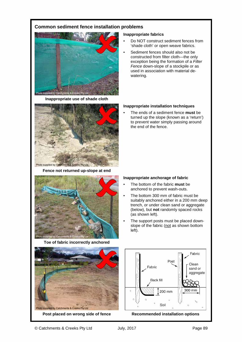
© Catchments & Creeks Pty Ltd July, 2017 Page 89
Common sediment fence installation problems
Inappropriate fabrics · Do NOT construct sediment fences from
‘shade cloth’ or open weave fabrics. · Sediment fences should also not be
constructed from filter cloth—the only exception being the formation of a Filter Fence down-slope of a stockpile or as used in association with material de-watering.
Inappropriate use of shade cloth
Inappropriate installation techniques · The ends of a sediment fence must be
turned up the slope (known as a ‘return’) to prevent water simply passing around the end of the fence.
Fence not returned up-slope at end
Inappropriate anchorage of fabric · The bottom of the fabric must be
anchored to prevent wash-outs. · The bottom 300 mm of fabric must be
suitably anchored either in a 200 mm deep trench, or under clean sand or aggregate (below), but not randomly spaced rocks (as shown left).
· The support posts must be placed down-slope of the fabric (not as shown bottom left).
Toe of fabric incorrectly anchored
Post placed on wrong side of fence Recommended installation options

© Catchments & Creeks Pty Ltd July, 2017 Page 90
U-Shaped sediment trap – suitable for minor concentrated flow
U-shaped sediment traps · A Type 3 sediment trap. · U-shaped sediment traps are commonly
used as coarse sediment traps within table drains on medium to steep gradients.
· The sediment fence must be constructed in a U-shape, not formed in a shallow arc, or placed straight across the drain.
· A spill-through weir is usually required to prevent flow bypassing in drains placed on a medium gradient.
· The width of the sediment trap is usually determined by the width of the excavator bucket used for sediment removal.
· Filter tubes can be integrated into the trap (forming a Filter Tube Dam) to increase the trap’s hydraulic capacity and to improve the treatment of low-flows.
· On low-gradient drains, preference should be given to the use of Check Dam Sediment Traps.
· Note: spill-through weirs are only effective if the weir crest is at least 300 mm high, and the weir crest is below the height of the ground at the trap’s inlet.
U-shaped sediment trap
U-shaped sediment trap in steep drain
Installation of U-shaped sediment traps · A sediment fence must not be placed
straight across the drain. · The correct flow condition is shown below.
· A U-shape sediment trap must not be
formed in a ‘shallow’ arc across the drain as shown (left), but if the drain is wide, a semi-circular shape trap with spill-through weir can be used.
Inappropriate installation
Inappropriate installation
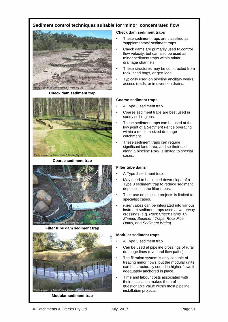
© Catchments & Creeks Pty Ltd July, 2017 Page 91
Sediment control techniques suitable for ‘minor’ concentrated flow
Check dam sediment traps · These sediment traps are classified as
‘supplementary’ sediment traps. · Check dams are primarily used to control
flow velocity, but can also be used as minor sediment traps within minor drainage channels.
· These structures may be constructed from rock, sand bags, or geo-logs.
· Typically used on pipeline ancillary works, access roads, or in diversion drains.
Check dam sediment trap
Coarse sediment traps · A Type 3 sediment trap. · Coarse sediment traps are best used in
sandy soil regions. · These sediment traps can be used at the
low point of a Sediment Fence operating within a medium-sized drainage catchment.
· These sediment traps can require significant land area, and so their use along a pipeline RoW is limited to special cases.
Coarse sediment trap
Filter tube dams · A Type 2 sediment trap. · May need to be placed down-slope of a
Type 3 sediment trap to reduce sediment deposition in the filter tubes.
· Their use on pipeline projects is limited to specialist cases.
· Filter Tubes can be integrated into various instream sediment traps used at waterway crossings (e.g. Rock Check Dams, U-Shaped Sediment Traps, Rock Filter Dams, and Sediment Weirs).
Filter tube dam sediment trap
Modular sediment traps · A Type 3 sediment trap. · Can be used at pipeline crossings of rural
drainage lines (overland flow paths). · The filtration system is only capable of
treating minor flows, but the modular units can be structurally sound in higher flows if adequately anchored in place.
· Time and labour costs associated with their installation makes them of questionable value within most pipeline installation projects.
Modular sediment trap

© Catchments & Creeks Pty Ltd July, 2017 Page 92
De-watering sediment controls
Filter bags · Commercial filter bags are suitable for the
treatment of low flow rates. · The bags collect only coarse-grained
sediments—they provide minimal control of turbidity levels.
· It is important to ensure that there are suitable means of collecting and removing the bags once they are full of sediment.
· Placing the filter bags within a mini skip (drainage plug removed) can reduce the complications of removing the used bags.
Filter bag
Filter fence · Suitable for the coarse and fine-grained
soils, but not for turbidity control. · Non-woven fabrics must be used. Compost berms · Can provide good filtration and limited
turbidity control. · Compost-filled socks (Filter Socks) can
also be used. · Performance of both systems can be
improved if incorporated with a substantial grass filter bed (Buffer Zone). Filter fence
Filter ponds · Used on flat or near-flat ground. · Most effective for the treatment of water
containing coarse-grained sediment. · Limited control over turbidity, unless used
on highly porous soil. · Diameter of the pond and the composition
of the filter wall depends on the soil type and design flow rate.
· Performance can be improved if located adjacent a substantial grass filter bed (Buffer Zone).
Filter pond
Filter tubes · Commercial filter tubes are suitable for the
treatment of low to medium flow rates. · Filter tubes collect only coarse-grained
sediments, with minimal control of turbidity.
· It is important to ensure that there are suitable means of collecting and removing the filter tubes once full of sediment.
· Placing the filter tube up-slope of a substantial grass filter bed can improve the collection of fine sediments and turbidity control. Filter tube
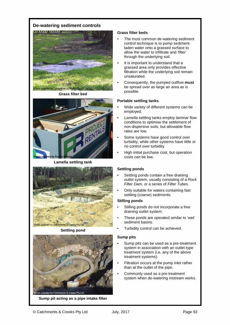
© Catchments & Creeks Pty Ltd July, 2017 Page 93
De-watering sediment controls
Grass filter beds · The most common de-watering sediment
control technique is to pump sediment-laden water onto a grassed surface to allow the water to infiltrate and ‘filter’ through the underlying soil.
· It is important to understand that a grassed area only provides effective filtration while the underlying soil remain unsaturated.
· Consequently, the pumped outflow must be spread over as large an area as is possible. Grass filter bed
Portable settling tanks · Wide variety of different systems can be
employed. · Lamella settling tanks employ laminar flow
conditions to optimise the settlement of non-dispersive soils, but allowable flow rates are low.
· Some systems have good control over turbidity, while other systems have little or no control over turbidity.
· High initial purchase cost, but operation costs can be low.
Lamella settling tank
Settling ponds · Settling ponds contain a free draining
outlet system, usually consisting of a Rock Filter Dam, or a series of Filter Tubes.
· Only suitable for waters containing fast settling (coarse) sediments.
Stilling ponds · Stilling ponds do not incorporate a free
draining outlet system. · These ponds are operated similar to ‘wet’
sediment basins. · Turbidity control can be achieved. Settling pond
Sump pits · Sump pits can be used as a pre-treatment
system in association with an outlet-type treatment system (i.e. any of the above treatment systems).
· Filtration occurs at the pump inlet rather than at the outlet of the pipe.
· Commonly used as a pre-treatment system when de-watering instream works.
Sump pit acting as a pipe intake filter

© Catchments & Creeks Pty Ltd July, 2017 Page 94