mentor.ieee.org · web viewa block length for thz-sc phy shall be 64 chips. the pilot word (pw)...
TRANSCRIPT

September 2016 IEEE P802.15-16-0595-01-003d
IEEE P802.15Wireless Personal Area Networks
Project IEEE P802.15 Working Group for Wireless Personal Area Networks (WPANs)
Title Proposal for IEEE802.15.3d – THz PHY
Date Submitted
9 15 September 2016
Source Thomas Kürner on behalf of TU Braunschweig, NICT, Hiroshima University, Glasgow University
Voice:Fax:E-mail: [email protected]
Re: In response to TG3d Call for Proposals (15-15-0936-04-003d)
Abstract Draft proposal PHY section (section 11b)
Purpose To be considered in the IEEE802.15.3d standard
Notice This document has been prepared to assist the IEEE P802.15. It is offered as a basis for discussion and is not binding on the contributing individual(s) or organization(s). The material in this document is subject to change in form and content after further study. The contributor(s) reserve(s) the right to add, amend or withdraw material contained herein.
Release The contributor acknowledges and accepts that this contribution becomes the property of IEEE and may be made publicly available by P802.15.
Submission Page TU Braunschweig, NICT et. al.

September 2016 IEEE P802.15-16-0595-01-003d
List of contributorsThomas Kürner TU BraunschweigAlexander Fricke TU BraunschweigSebastian Rey NICTBile Peng TU BraunschweigIwao Hosako, NICT NICTAkifumi Kasamatsu, NICT NICTNorihiko Sekine, NICT NICTHiroyo Ogawa, NICT NICTMinoru Fujishima Hiroshima UniversityAnthony Kelly Glasgow University
Submission Page TU Braunschweig, NICT et. al.

September 2016 IEEE P802.15-16-0595-01-003d
11b PHY specification for THz.........................................................................................511b.1 General requirements......................................................................................................5
11b.1.1 Regulatory Information...........................................................................................................511b.1.2 RF power measurements.......................................................................................................511b.1.3 Unwanted emissions..............................................................................................................511b.1.4 RF channelization.................................................................................................................. 511b1.5 Transmit PSD mask................................................................................................................811b1.6 Error Vector Magnitude Calculation........................................................................................911b1.7 THz-PHY management...........................................................................................................9
11b1.7.1 Supported MCSs..............................................................................................................911b1.7.2 THz-PHY PIB................................................................................................................. 10
11b.2 THz-SC PHY.................................................................................................................12
11b.2.1 Channelization of THz-SC PHY...........................................................................................1211b.2.2 Modulation and coding.........................................................................................................12
11b.2.2.1 MCS dependent parameters.........................................................................................1211b.2.2.2 Header dependent parameters.....................................................................................1411b.2.2.3 Timing-related parameters............................................................................................1411b.2.2.4 Frame-related parameters............................................................................................1511b.2.2.5 Modulation....................................................................................................................1611b.2.2.6 Forward Error Correction..............................................................................................1711b.2.2.7 Stuff bits........................................................................................................................1711b.2.2.8 Code spreading.............................................................................................................1711b.2.2.9 Scrambling....................................................................................................................17
11b.2.3 THz-SC PHY frame format...................................................................................................1711b.2.3.2.1 THz-SC PHY header.............................................................................................18
11b.2.3.3 THz-SC PHY Payload field...........................................................................................2111b.2.3.3.1 THZ-SC PHY Payload scrambling.........................................................................2111b.2.3.3.2 Modulation.............................................................................................................2111b.2.3.3.3 FEC....................................................................................................................... 21
11b.2.3.4 Pilot word and PPRE....................................................................................................2111b.2.3.4.1 Block and pilot word...............................................................................................2111b.2.3.4.2 PPRE..................................................................................................................... 21
11b.2.4 Transmitter specifications.....................................................................................................2211b.2.4.1 EVM Requirement.........................................................................................................2211b.2.4.2 Symbol rate................................................................................................................... 2211b.2.4.3 Transmit power-on and power-down ramp...................................................................22
11b.2.5 Receiver specifications.........................................................................................................2211b.2.5.1 Error rate criterion.........................................................................................................2211b.2.5.2 Receiver sensitivity.......................................................................................................2311b.2.5.3 Receiver maximum input level......................................................................................23
11b.2.6 PHY layer timing.................................................................................................................. 2311b.2.6.1 Interframe space...........................................................................................................2311b.2.6.2 Receive-to-transmit turnaround time.............................................................................2411b.2.6.3 Transmit-to-receive turnaround-time.............................................................................2411b.2.6.4 Time between successive transmissions......................................................................2411b.2.6.5 Channel switch..............................................................................................................24
11b.2.7 PHY management for THZ-SC PHY....................................................................................2411b.2.7.1 Maximum frame size.....................................................................................................2411b.2.7.2 Maximum transfer unit size...........................................................................................24
Submission Page TU Braunschweig, NICT et. al.

September 2016 IEEE P802.15-16-0595-01-003d
11b.2.7.3 Minimum fragment size.................................................................................................25
11b.3 THz-OOK PHY..............................................................................................................25
11b3.1 Channelization for THZ-OOK PHY....................................................................................2511b.3.2 Modulation and Coding........................................................................................................25
11b.3.2.1 Modulation................................................................................................................2511b.3.2.2 Forward Error Correction..............................................................................................2611b.3.2.3 MCS dependent parameters.........................................................................................26
Submission Page TU Braunschweig, NICT et. al.

September 2016 IEEE P802.15-16-0595-01-003d
Insert the following clause as Clause 11b:
11b PHY specification for THz
11b.1 General requirements A compliant THz PHY shall implement at least one of the following PHY modes:
a) THz single carrier mode PHY (THz-SC PHY), as defined in 11b.2.b) THz on-off keying mode PHY (THz-OOK PHY), as defined in 11b.3.
Unless otherwise stated, in all figures in this clause the ordering of the octets and bits as they are presented to the THz PHY for modulation is the same as defined in 6.1.
11b.1.1 Regulatory Information
The THz PHY operating frequency is within the 252.72 – 321.84 GHz range as allocated and not identified by the radio regulations. The radio regulations have allocated the spectrum in the range of 252-275 GHz for the use of mobile and fixed services and allows the national administrations to allow the use of THz communications above 275 GHz as long as passive services in this band are protected from harmful interference.
11b.1.2 RF power measurements
Unless otherwise stated, all RF power measurements for the purpose of this standard, either transmit or receive, shall be made based on EIRP and any radiated measurements shall be corrected to compensate for the antenna gain in the implementation. The gain of the antenna is the maximum estimated gain by the manufacturer.
11b.1.3 Unwanted emissions
Conformant implementations shall comply with the in-band and out-of-band emissions for all operational modes as set by the applicable regulatory bodies.
11b.1.4 RF channelization
The THz PHY uses the channels defined in Figure 11b-1 and Table 11b-1.
Submission Page TU Braunschweig, NICT et. al.

September 2016 IEEE P802.15-16-0595-01-003d
f GHz
Ch1
Ch2
Ch3
Ch4
Ch5
Ch6
Ch7
Ch8
Ch9
Ch10
Ch11
Ch12
Ch13
Ch14
Ch15
Ch16
Ch17
Ch18
Ch19
Ch20
Ch21
Ch22
Ch23
Ch24
f GHzCh33
Ch34
Ch35
Ch36
Ch37
Ch38
Ch39
Ch40
Ch41
Ch42
Ch43
f GHzCh 49 Ch 50 Ch 51 Ch 52 Ch 53 Ch 54
f GHz
Ch44
304.56252.72
Ch 57 Ch 58 Ch 59 Ch 60
BW(GHz)
2.16
4.32
8.64
12.96
17.28 Ch 62 Ch 63 Ch 64
f GHz
f GHzCh 66 Ch 6725.92
f GHzCh 6851.84
265 270 275 280 285 290 295 300 305 310 315 320260255250
Ch45
Ch46
Ch47
Ch48
Ch25
Ch26
Ch27
Ch28
Ch29
Ch30
Ch31
Ch32
Ch 55 Ch 56
Ch 65
Ch 61
321.84
Figure 11b-1— THz PHY Channel Assignments
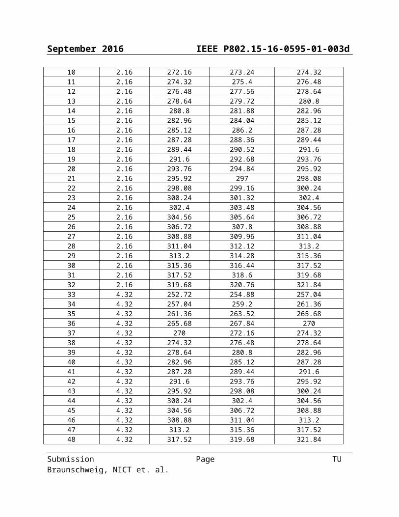
Table 11b-1—THz PHY channelization
CHNL_ID Bandwidth Start frequencya Center frequency Stop frequencya
1 2.16 252.72 253.8 254.882 2.16 254.88 255.96 257.043 2.16 257.04 258.12 259.24 2.16 259.2 260.28 261.365 2.16 261.36 262.44 263.526 2.16 263.52 264.6 265.687 2.16 265.68 266.76 267.848 2.16 267.84 268.92 2709 2.16 270 271.08 272.1610 2.16 272.16 273.24 274.3211 2.16 274.32 275.4 276.4812 2.16 276.48 277.56 278.6413 2.16 278.64 279.72 280.814 2.16 280.8 281.88 282.9615 2.16 282.96 284.04 285.12
Submission Page TU Braunschweig, NICT et. al.
September 2016 IEEE P802.15-16-0595-01-003d
16 2.16 285.12 286.2 287.2817 2.16 287.28 288.36 289.4418 2.16 289.44 290.52 291.619 2.16 291.6 292.68 293.7620 2.16 293.76 294.84 295.9221 2.16 295.92 297 298.0822 2.16 298.08 299.16 300.2423 2.16 300.24 301.32 302.424 2.16 302.4 303.48 304.5625 2.16 304.56 305.64 306.7226 2.16 306.72 307.8 308.8827 2.16 308.88 309.96 311.0428 2.16 311.04 312.12 313.229 2.16 313.2 314.28 315.3630 2.16 315.36 316.44 317.5231 2.16 317.52 318.6 319.6832 2.16 319.68 320.76 321.8433 4.32 252.72 254.88 257.0434 4.32 257.04 259.2 261.3635 4.32 261.36 263.52 265.6836 4.32 265.68 267.84 27037 4.32 270 272.16 274.3238 4.32 274.32 276.48 278.6439 4.32 278.64 280.8 282.9640 4.32 282.96 285.12 287.2841 4.32 287.28 289.44 291.642 4.32 291.6 293.76 295.9243 4.32 295.92 298.08 300.2444 4.32 300.24 302.4 304.5645 4.32 304.56 306.72 308.8846 4.32 308.88 311.04 313.247 4.32 313.2 315.36 317.5248 4.32 317.52 319.68 321.8449 8.64 252.72 257.04 261.3650 8.64 261.36 265.68 27051 8.64 270 274.32 278.6452 8.64 278.64 282.96 287.2853 8.64 287.28 291.6 295.9254 8.64 295.92 300.24 304.5655 8.64 304.56 308.88 313.256 8.64 313.2 317.52 321.8457 12.96 252.72 259.2 265.6858 12.96 265.68 272.16 278.6459 12.96 278.64 285.12 291.660 12.96 291.6 298.08 304.5661 12.96 304.56 311.04 317.5262 17.28 252.72 261.36 270
Submission Page TU Braunschweig, NICT et. al.

September 2016 IEEE P802.15-16-0595-01-003d
63 17.28 270 278.64 287.2864 17.28 287.28 295.92 304.5665 17.28 304.56 313.2 321.8466 25.92 252.72 265.68 278.6467 25.92 278.64 291.6 304.5668 51.84 252.72 278.64 304.56
The start and stop frequencies are nominal values. The frequency spectrum of the transmitted signal needs to conform to the transmit power spectral density (PSD) mask for the PHY mode as well as any regulatory requirement.
The bandwidth of all channels are integer multiples of 2.16 GHz. The center frequencies for channels, whose CHNL_ID is 33-68 are integer multiples of 2.16 GHz. The channel whose CHNL_ID is [tbd] shall be defined as default channel.
11b1.5 Transmit PSD mask
The transmitted spectrum for both THz SC-PHY and THz OOK-PHY shall adhere to the transmit spectrum density (PSD) mask shown in Figure 11b-2. For the transmit mask measurements, the resolution bandwidth is set to 3 MHz and video bandwidth to 300 kHz. During OOK modulation, transmitters shall meet the showwon PSD mask, with an additional single line spectrum of 40 dB above the 0 dB line in Figure 11b-2 within the frequency band of [–6 MHz,+6 MHz] from the carrier frequency.
Figure 11b-2— Generic transmit spectral mask
Table 11b-2—Transmit spectrum mask limit
Frequency Relative Limit [dBr]¿ f −f c∨≤ f 1 0
f 1≤∨f −f c∨≤ f 2 −20(|f −f c|−f 1)/( f 2−f 1)f 2≤∨f −f c∨≤ f 3 −20−5∙ (|f − f c|−f 2)/( f 3−f 2)f 3≤∨f −f c∨≤ f 4 −25−5∙ (|f − f c|−f 3)/ (f 4−f 3)
Submission Page TU Braunschweig, NICT et. al.

September 2016 IEEE P802.15-16-0595-01-003d
¿ f −f c∨≥ f 4 −30
Table 11b-3—Transmit spectrum mask parameters [values tbd]Channel Bandwidth [GHz] f 1[GHz ] f 2[GHz ] f 3[GHz ] f 4[GHz ]
2.160 1.0804.320 2.1608.640 4.320
12.960 6.48017.280 8.64025.920 12.96051.840 25.920
11b1.6 Error Vector Magnitude Calculation
The transmitted spectrum for THz PHY using a single channel shall be measured and calculated using the method defined in 11.1.7.1
11b1.7 THz-PHY management
11b1.7.1 Supported MCSsThe Supported data rates field in the DEV capabilities field, as described in 6.4.11d (THz capability).
Note for the preparation of 6.4.11d: In 6.4.11d the THz device field capability format can be based on figure 6-88b with b0 to b23 identical and the following bits different:
Bits Capability meaningb24-b29 SC supported MCSmodulation
formatsb24: SC π/2-shift BPSK supportedb25: SC π/2-shift QPSK supportedb26: SC π/2-shift 8-PSK supportedb27: SC π/2-shift 8-APSK supportedb28: SC 16-QAM supportedb29: SC 64-QAM supported
b30 OOK spreading b30: OOK spreading usedb31 Reservedb31-b37 Channel bandwidth supported b31: 2.16 GHz
b32: 4.32 GHzb33: 8.64 GHzb34: 12.96 GHzb35: 17.28 GHzb36: 25.92 GHzb37: 51.84 GHz
b38 Reservedb39-b70 Spectrum part supported Spectrum parts given in the smallest
granularity of 2.16 GHz; spectrum range corresponds to the spectrum ranges defined by the spectrum ranges of CHNL_ID 1 to
Submission Page TU Braunschweig, NICT et. al.

September 2016 IEEE P802.15-16-0595-01-003d
32)b(38+ CHNL_ID)Note: in the final draft the spectrum may be given in absolute numbers here
B71 Reserved
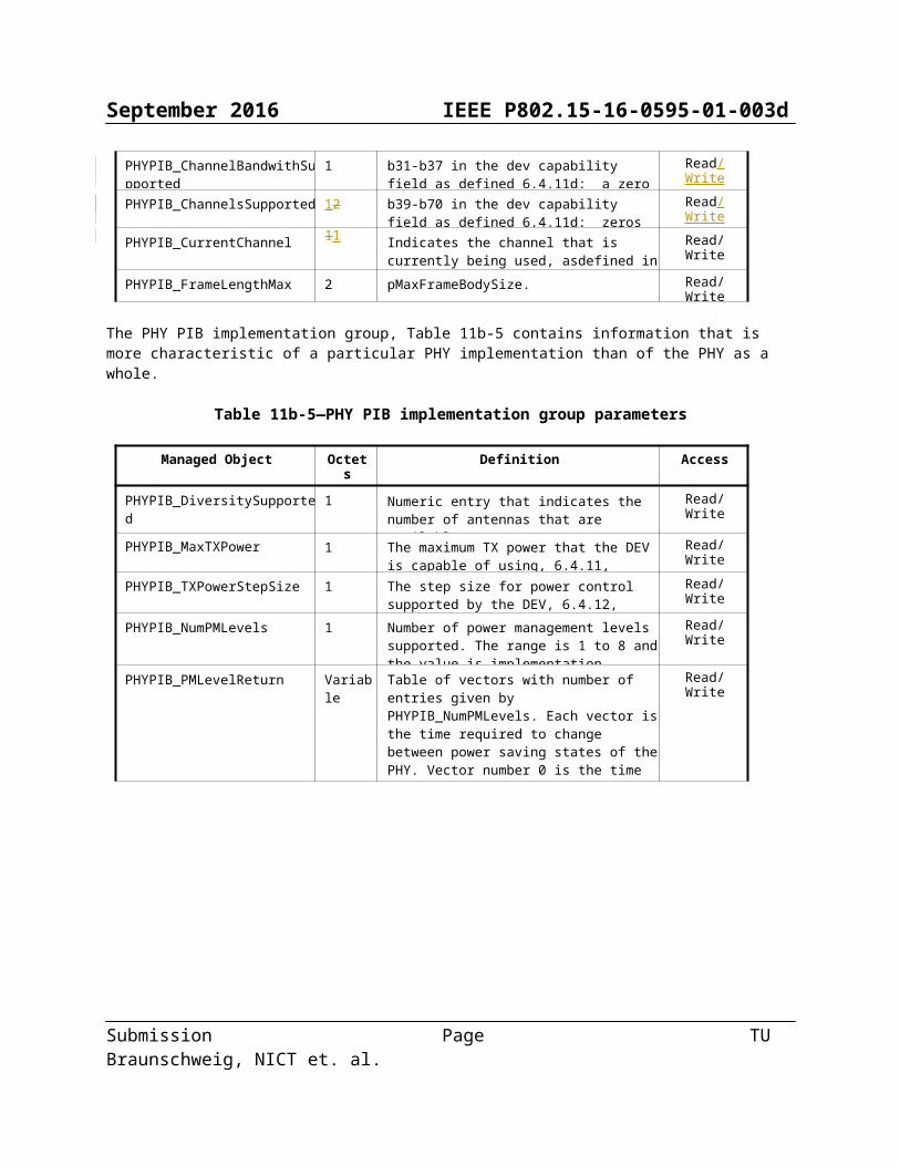
11b1.7.2 THz-PHY PIBThe PHY dependent PIB values for the THz PHY are given in Table 11b-4 and Table 11b-5. The PHY PIB characteristics group, Table XX, contains information that is common to most implementations.
Table 11b-4 -PHY PIB characteristics group parameters
Managed Object Octets Definition Access
PHYPIB_Type 1 0x03 = THz PHY Read/Write
PHYPIB_Mode 1 bit 1 = THz-SC PHYbit 2 = THz-OOK PHYbit 3-8 = ReservedA bit is set to one if the associated PHY is supported, and is set to zero otherwise.
Read/Write
PHYPIB_RegDomainsSupported Variable One octet for each regulatory domain supported, as defined for PHYPIB_CurrentRegDomain.
Read/Write
PHYPIB_CurrentRegDomain 1 0x00 = European Telecommunications Standards Institute (ETSI)0x01 = Federal Communications Commission (FCC)0x02 = Industry Canada (IC)0x03 = Association of Radio Industries and Businesses (ARIB)
Read/Write
PHYPIB_DataRateVector Variable One octet for each supported MCS. The msb indicates the THz PHY mode, as in PHYPIB_Mode, and the last six lsbs contain the MCS supported for that mode using the encoding for that PHY mode.
Read/Write
PHYPIB_ChannelBandwithSupported
1 b31-b37 in the dev capability field as defined 6.4.11d; a zero is appended in the lsb
Read/Write
PHYPIB_ChannelsSupported 12 b39-b70 in the dev capability field as defined 6.4.11d; zeros are appended in the 7 lsb
Read/Write
PHYPIB_CurrentChannel 11 Indicates the channel that is currently being used, asdefined in 11b.1.4.
Read/Write
PHYPIB_FrameLengthMax 2 pMaxFrameBodySize. Read/Write
The PHY PIB implementation group, Table 11b-5 contains information that is more characteristic of a particular PHY implementation than of the PHY as a whole.
Submission Page TU Braunschweig, NICT et. al.

September 2016 IEEE P802.15-16-0595-01-003d
Table 11b-5—PHY PIB implementation group parameters
Managed Object Octets Definition Access
PHYPIB_DiversitySupported 1 Numeric entry that indicates the number of antennas that are available.
Read/Write
PHYPIB_MaxTXPower 1 The maximum TX power that the DEV is capable of using, 6.4.11, implementation dependent.
Read/Write
PHYPIB_TXPowerStepSize 1 The step size for power control supported by the DEV, 6.4.12, implementation dependent.
Read/Write
PHYPIB_NumPMLevels 1 Number of power management levels supported. The range is 1 to 8 and the value is implementation dependent.
Read/Write
PHYPIB_PMLevelReturn Variable Table of vectors with number of entries given by PHYPIB_NumPMLevels. Each vector is the time required to change between power saving states of the PHY. Vector number 0 is the time required to change the PHY from the off state to a state where it is ready to receive commands. Other values are implementation dependent.
Read/Write
Submission Page TU Braunschweig, NICT et. al.
September 2016 IEEE P802.15-16-0595-01-003d
11b.2 THz-SC PHY The THz-SC PHY is designed for extremely high PHY-SAP payload-bit rates between 2 Gb/s and 13 Gb/s using a single channel with a band width of 2.16 GHz and the maximum 250 Gb/s using a bandwidth of 51.92 GHz.
The THZ-SC PHY supports π/2-shift BPSK, π/2-shift QPSK, π/2-shift 8-PSK, π/2-shift APSK, 16-QAM and 64-QAM. The modulation of π/2-shift BPSK is also used for preamble and header sequences, and all other modulations are used for a payload only. The modulations of π/2-shift BPSK and π/2-shift QPSK are mandatory for THz-SC PHY and other modulations are optional. The FEC scheme is specified by two LDPC codes with a code rate of 14/15 and a code rate of 11/15. These two LDPC codes are mandatory for THz-SC PHY
11b.2.1 Channelization of THz-SC PHY
The RF channels are defined in Figure 11b-1 and Table 11b-1. A compliant implementation shall support at least 1 channel from the channels allocated for operation by its corresponding regulatory body.
The PHYPIB_CurrentChannel is the CHNL_ID of the current channel. For the purpose of the Remote Scan Request and Remote Scan Response commands, as described in 7.5.7.3 and 7.5.7.4, respectively, the Channel Index field is the CHNL_ID in Table 11b-1 in 11b.1.4.
11b.2.2 Modulation and coding
11b.2.2.1 MCS dependent parametersThe MCS dependent parameters shall be set according to Table 11b-6. The chip rate for all THz-SC PHY MCS is given in Table 11b-8. The data rates in the table are approximate values.
Table 11b-6—MCS dependent parametersMCS identifier bandwidth
(GHz)modulation FEC rate data rate (Gb/s)
w/o PWdata rate (Gb/s)
w/o PW0 2,16 BPSK 11/15 1,3493 1,18071 2,16 BPSK 14/15 1,7173 1,50272 2,16 QPSK 11/15 2,6987 2,36133 2,16 QPSK 14/15 3,4347 3,00534 2,16 8-PSK 11/15 4,0480 3,54205 2,16 8-PSK 14/15 5,1520 4,50806 2,16 8-APSK 11/15 4,0480 3,54207 2,16 8-APSK 14/15 5,1520 4,50808 2,16 16QAM 11/15 5,3973 4,72279 2,16 16-QAM 14/15 6,8693 6,010710 2,16 64-QAM 11/15 8,0960 7,084011 2,16 64-QAM 14/15 10,3040 9,016012 4,32 BPSK 11/15 2,6987 2,361313 4,32 BPSK 14/15 3,4347 3,005314 4,32 QPSK 11/15 5,3973 4,722715 4,32 QPSK 14/15 6,8693 6,010716 4,32 8-PSK 11/15 8,0960 7,084017 4,32 8-PSK 14/15 10,3040 9,016018 4,32 8-APSK 11/15 8,0960 7,084019 4,32 8-APSK 14/15 10,3040 9,0160
Submission Page TU Braunschweig, NICT et. al.

September 2016 IEEE P802.15-16-0595-01-003d
20 4,32 16QAM 11/15 10,7947 9,445321 4,32 16-QAM 14/15 13,7387 12,021322 4,32 64-QAM 11/15 16,1920 14,168023 4,32 64-QAM 14/15 20,6080 18,032024 8,64 BPSK 11/15 5,3973 4,722725 8,64 BPSK 14/15 6,8693 6,010726 8,64 QPSK 11/15 10,7947 9,445327 8,64 QPSK 14/15 13,7387 12,021328 8,64 8-PSK 11/15 16,1920 14,168029 8,64 8-PSK 14/15 20,6080 18,032030 8,64 8-APSK 11/15 16,1920 14,168031 8,64 8-APSK 14/15 20,6080 18,032032 8,64 16QAM 11/15 21,5893 18,890733 8,64 16-QAM 14/15 27,4773 24,042734 8,64 64-QAM 11/15 32,3840 28,336035 8,64 64-QAM 14/15 41,2160 36,064036 12,96 BPSK 11/15 8,0960 7,084037 12,96 BPSK 14/15 10,3040 9,016038 12,96 QPSK 11/15 16,1920 14,168039 12,96 QPSK 14/15 20,6080 18,032040 12,96 8-PSK 11/15 24,2880 21,252041 12,96 8-PSK 14/15 30,9120 27,048042 12,96 8-APSK 11/15 24,2880 21,252043 12,96 8-APSK 14/15 30,9120 27,048044 12,96 16-QAM 11/15 32,3840 28,336045 12,96 16-QAM 14/15 41,2160 36,064046 12,96 64-QAM 11/15 48,5760 42,504047 12,96 64-QAM 14/15 61,8240 54,096048 17,28 BPSK 11/15 10,7947 9,445349 17,28 BPSK 14/15 13,7387 12,021350 17,28 QPSK 11/15 21,5893 18,890751 17,28 QPSK 14/15 27,4773 24,042752 17,28 8-PSK 11/15 32,3840 28,336053 17,28 8-PSK 14/15 41,2160 36,064054 17,28 8-APSK 11/15 32,3840 28,336055 17,28 8-APSK 14/15 41,2160 36,064056 17,28 16QAM 11/15 43,1787 37,781357 17,28 16-QAM 14/15 54,9547 48,085358 17,28 64-QAM 11/15 64,7680 56,672059 17,28 64-QAM 14/15 82,4320 72,128060 25,92 BPSK 11/15 16,1920 14,168061 25,92 BPSK 14/15 20,6080 18,032062 25,92 QPSK 11/15 32,3840 28,336063 25,92 QPSK 14/15 41,2160 36,064064 25,92 8-PSK 11/15 48,5760 42,504065 25,92 8-PSK 14/15 61,8240 54,096066 25,92 8-APSK 11/15 48,5760 42,504067 25,92 8-APSK 14/15 61,8240 54,0960
Submission Page TU Braunschweig, NICT et. al.

September 2016 IEEE P802.15-16-0595-01-003d
68 25,92 16QAM 11/15 64,7680 56,672069 25,92 16-QAM 14/15 82,4320 72,128070 25,92 64-QAM 11/15 97,1520 85,008071 25,92 64-QAM 14/15 123,6480 108,192072 51,84 BPSK 11/15 32,3840 28,336073 51,84 BPSK 14/15 41,2160 36,064074 51,84 QPSK 11/15 64,7680 56,672075 51,84 QPSK 14/15 82,4320 72,128076 51,84 8-PSK 11/15 97,1520 85,008077 51,84 8-PSK 14/15 123,6480 108,192078 51,84 8-APSK 11/15 97,1520 85,008079 51,84 8-APSK 14/15 123,6480 108,192080 51,84 16QAM 11/15 129,5360 113,344081 51,84 16-QAM 14/15 164,8640 144,256082 51,84 64-QAM 11/15 194,3040 170,016083 51,84 64-QAM 14/15 247,2960 216,3840
A block length for THZ-SC PHY shall be 64 chips. The pilot word (PW) length for THz-SC PHY shall be 0 or 8 chips. The PW length of 8 is mandatory and that of 0 chips is optional.
11b.2.2.2 Header dependent parametersThe header dependent parameters shall be set according to Table 11b-7. The headers use an extended Hamming (EH) code, as defined in 11a.2.3.2.3.
Table 11b-7— Header rate dependent parameters
Header rate (Mb/s)
Modulation Scheme
Spreading Factor, LSF
FEC
PW length (chips),
LPW
Code bits per
bsubblock, LCBPS
Number of occupied
bsubblocks, Nsubblock_hdr
Number of stuff bits,
LSTUFF
162 /2-shift BPSK 4 EH 8 14 19 40
11b.2.2.3 Timing-related parametersTable 11b-8 lists the general timing parameters associated with the THz-SC PHY.
Table 11b-8—Timing-related parametersParameter Description Value Unit Formula
Rc Chip rate 1760 … 42240 Mchip/s B×1760/[2.16GHz]
TC Chip duration ~0.568 … ~0.023 ns 1/RC
Lblock block length 512 chips
LPW Pilot word length 0 8 chips
TPW Pilot word duration 0 ~4.544 … ~1.840 ns
Submission Page TU Braunschweig, NICT et. al.

September 2016 IEEE P802.15-16-0595-01-003d
LDC Data chips per block 64 56 chips
Tblock block duration ~37.504 … ~1.472 ns Lblock×Tc
Rblock block rate 26.663 … 679.347 MHz 1/ Tblock
11b.2.2.4 Frame-related parametersThe frame parameters associated with the PHY are listed in Table 11b-9 where CEIL is the ceiling function, which returns the smallest integer value greater than or equal to its argument. The maximum frame duration occurs when the number of octets in the PHY Payload field is 524288.
Table 11b-9—Frame-related parameters
Parameter Description Value
NSYNC Number of code repetitions in the SYNC sequence 14 or 28
TSYNC Duration of the SYNC sequence ~1.019 µs or ~2.036 µs
NSFD Number of code repetitions in SFD 1
TSFD Duration of the SFD ~0.073 µs
NCES Number of code repetitions i the CES 11
TCES Duration of the CES ~0.8000 µs
Npre Number of code repetitions in the PHY preamble 26 or 40
Tpre Duration of the PHY preamble ~1.891 µs or ~2.909 µs
Lhdr Length of the header in octets 14
Nblock_hdr Number of subblocks in the base frame header CEIL[Lhdr × 8 × LSF / (Lsubblock – LPW)]
Thdr Duration of the base frame header Nblock_hdr × Tblock =~0.691 µs
Lpayload Length of frame payload in octets Variable
Lhds Length of the MAC header in octets 4
Nsubframe Number of subframes Variable between 1 and 256
LFCS Length of FCS in octest 4
LMFBLength of MAC frame body in octets Lpayload + (Lhds + LFCS) Nframe
NPRPE Number of code repetitions in the PPRE 26
TPRPE Duration of PPRE ~1.891 µs
Nblock_PRPE Number of blocks between PPRE Variable between 1024 and 4096
NCBPCNumber of coded bits per chip in the MAC frame body
1,2,3,3,4 and 6 for BPSK, QPSK, 8PSK, 8-APSK, 16-QAM and 64 QAM, respectively
Submission Page TU Braunschweig, NICT et. al.

September 2016 IEEE P802.15-16-0595-01-003d
NPPRE_frame Number of PPREs per frame CEIL[(Nblock_MFB / (LBlock × 512)] - 1
TPPRE_interval Interval of PPRE insertion Tblock × Nbloc_PPRE + TPW
LCBPSNumber of coded bits per subblock in the MAC frame body (Lblock – LPW) x NCBPC
Nblock_MFB Number of blocks in the MAC frame body CEIL[(LMFB × 8) / (RFEC × LCBPS)] (RFEC: FEC Rate)
TMFB Duration of the MAC and PHY frame body Nblock_MFB × Tblock
Tdatafield Duration of the PHY datafield TMFB + (NPPRE_frame + 1) × TPW + NPPRE_frame× TPPRE
Tframe Duration of the frame Tpre + Thdr + Tdatafield
11b.2.2.5 ModulationAfter channel encoding and spreading, the bits shall be inserted into the constellation mapper. The constellations of π/2-shift BPSK, π/2-shift QPSK and π/2-shift 8-PSK used for the THz-SC PHY are the same as illustrated in Figure 11-10 (a), (b) and (c), respectively, in 11.2.2.5.1 and 12.2.2.5.2. The constellations of 16QAM and 64QAM used for the THz-SC PHY are the same as illustrated in Figure 11-29 in11.3.2.6.
The constellation diagram of π/2-shift 8-APSK is shown in figure 11b-4. The The π/2-shift 8-APSK shall encode 3 bits per symbol, with input input bit d1 being the earliest in the stream. The π/2-rotation is performed in the same manner as in 11.2.2.5.1.
Figure 11b-4— π/2-shift 8-APSK
11b.2.2.6 Forward Error CorrectionThe forward error correction (FEC) schemes are specified in this subclause. Supporting the following two rate-compatible LDPC codes, i.e. a rate-14/15 LDPC(1440,1344) code as defined in 11.2.2.6.3 and a rate-11/15 LDPC(1440,1056) code as defined in 11a.2.2.6, are mandatory for THz-SC PHY
11b.2.2.7 Stuff bitsStuff bits shall be added to the end of the encoded MAC frame body if the number of the encoded data bits is not an
Submission Page TU Braunschweig, NICT et. al.

September 2016 IEEE P802.15-16-0595-01-003d
integer multiple of the length of the data portion in the block. The number of stuff bits is computed for each subframe if standard aggregation is employed. The calculation of stuff bits follows the definition in 11a.2.2.7.
11b.2.2.8 Code spreading
Table 11a-12 is a spreading table for a frame header. The most significant bit of the output shall be transmitted first in Table 11a-12.
11b.2.2.9 ScramblingThe frames shall be scrambled by modulo-2 addition of the data with the output of a PRBS generator, as defined in 11a.2.2.9.
11b.2.3 THz-SC PHY frame format
The THZ-SC PHY frame shall be formatted as illustrated in Figure 11-18.The Frame Header field for the PHY frame shall be formatted as illustrated in Figure 11a-4.
The PHY preamble is described in 11a.2.3.1. The MAC header is defined in 6.2. The PHY header is defined in 11b.2.3.2.1, and the HCS is defined in 11a.2.3.2.2. The header FEC is defined in 11a.2.3.2.3. The PHY Payload field consisting of the MAC frame body, the the pilot preambaple (PPRE) and stuff bits, is described in 11a.2.3.3. The PCES is described in 11a.2.3.4.2. The stuff bits are described in 11a.2.2.7.
11b.2.3.2.1 THz-SC PHY headerThe THz-SC PHY header shall be formatted as illustrated in Figure 11b-5.
Bits: b0-b6 b7 b8-b11 b12-b13 b14 b15-b35MCS Pilot word Scrambler seed ID PPRE Reserved Frame length
Figure 11b-5— PHY header format for THz-SC PHY
The MCS field shall be set according to the values in Table 11b10.
The Pilot Word field shall be set to one if the pilot word used in the current frame and shall be set to zero if otherwise.
The Scrambler Seed ID field contains the scrambler seed identifier value, as defined in 11.2.2.10.
The Frame Length field shall be an unsigned integer equal to the number of octets in the MAC frame body of a regular frame, excluding the FCS.
Table 11b10— Modulation and coding scheme
MCS MCS identifier
0000000 0
Submission Page TU Braunschweig, NICT et. al.

September 2016 IEEE P802.15-16-0595-01-003d
0000001 1
0000010 2
0000011 3
0000100 4
0000101 5
0000110 6
0000111 7
0001000 8
0001001 9
0001010 10
0001011 11
0001100 12
0001101 13
0001110 14
0001111 15
0010000 16
0010001 17
0010010 18
0010011 19
0010100 20
0010101 21
0010110 22
0010111 23
0011000 24
0011001 25
0011010 26
0011011 27
0011100 28
0011101 29
0011110 30
0011111 31
0100000 32
Submission Page TU Braunschweig, NICT et. al.

September 2016 IEEE P802.15-16-0595-01-003d
0100001 33
0100010 34
0100011 35
0100100 36
0100101 37
0100110 38
0100111 39
0101000 40
0101001 41
0101010 42
0101011 43
0101100 44
0101101 45
0101110 46
0101111 47
0110000 48
0110001 49
0110010 50
0110011 51
0110100 52
0110101 53
0110110 54
0110111 55
0111000 56
0111001 57
0111010 58
0111011 59
0111100 60
0111101 61
0111110 62
0111111 63
1000000 64
Submission Page TU Braunschweig, NICT et. al.

September 2016 IEEE P802.15-16-0595-01-003d
1000001 65
1000010 66
1000011 67
1000100 68
1000101 69
1000110 70
1000111 71
1001000 72
1001001 73
1001010 74
1010011 75
1010100 76
1010101 77
1010110 78
1010111 79
1011000 80
1011001 81
1011010 82
1011011 83
11b.2.3.3 THz-SC PHY Payload fieldThe THZ-SC PHY Payload field is the last component of the frame, and is constructed as shown in Figure 11-23.
The PHY Payload field shall be constructed as follows:a) Scramble the MAC frame body according to 11b.2.2.3.1.b) Encode the scrambled MAC frame body as specified in 11a.2.2.6.c) Add stuff bits to the encoded and scrambled MAC frame body according to 11b.2.2.7.d) Map the resulting MAC frame body onto the appropriate constellation as described in 11b.2.2.5.e) Build blocks from the resulting MAC frame body according to 11a.2.3.4.1.f) Insert PPRE periodically as described in 11b.2.3.4.2.
11b.2.3.3.1 THZ-SC PHY Payload scramblingThe THZ-SC PHY payload shall use the scrambling process defined in 11.2.2.10
11b.2.3.3.2 ModulationModulation for the MAC frame body is defined in 11b.2.2.5.
11b.2.3.3.3 FEC
Submission Page TU Braunschweig, NICT et. al.

September 2016 IEEE P802.15-16-0595-01-003d
FEC for the MAC frame body is defined in 11b.2.2.6.
11b.2.3.4 Pilot word and PPRE
11b.2.3.4.1 Block and pilot wordThe block and pilot word is defined as in 11a.2.3.4.1
11b.2.3.4.2 PPREThe PPRE is defined as in 11a.2.3.4.2
11b.2.4 Transmitter specifications
11b.2.4.1 EVM RequirementThe EVM of a compliant transmitter shall be measured and calculated as defined in 11.1.7 and shall notexceed the values given in Table 11b-11 for the indicated mode. Note that this requirement assumes a conducted measurement.
Table 11b-11 Max EVM
MCS Identifier Modulation FEC Rate Max. EVM [dB]0,12,24,36.48,60,72 BPSK 11/151,13,25,37,49,61,73 BPSK 14/152,14,26,38,50,62,74 QPSK 11/15 -123,15 QPSK 14/15 -154,16 8-PSK 11/155,17 8-PSK 14/156,18 8-APSK 11/157,19 8-APSK 14/158,20 16QAM 11/15 -189,21 16-QAM 14/15 -2210,22 64-QAM 11/15 -2511,23 64-QAM 14/15 -29
11b.2.4.2 Symbol rateThe THz SC PHY shall be capable of transmitting at the chip rate, as defined in Table 11b-8, to within ±25 s/s.The MAC parameter, pPHYClockAccuracy, shall be ±25 s/s.
11b.2.4.3 Transmit power-on and power-down rampThe transmit power-on ramp is defined as the time it takes for the RF power emitted by the compliant DEV to rise from less than 10% to greater than 90% of the maximum power to be transmitted in the frame.
The transmit power-on ramp shall be less than 9.3 ns.
The transmit power-down ramp is defined as the time it takes for the RF power emitted by the compliant DEV to fall from greater than 90% to less than 10% of the maximum power to be transmitted in the frame.
Submission Page TU Braunschweig, NICT et. al.

September 2016 IEEE P802.15-16-0595-01-003d
The transmit power-down ramp shall be less than 9.3 ns.
The transmit power ramps shall be constructed such that the emissions conform to the unwanted emissions specification defined in 11a.1.3.
11b.2.5 Receiver specifications
11b.2.5.1 Error rate criterionThe error rate criterion shall be a frame error rate (FER) of less than 8% with a frame payload length of 214 octets. The error rate should be determined at the PHY SAP interface after any error correction methods(excluding retransmission) required in the proposed device has been applied. The measurement shall beperformed in AWGN channel.
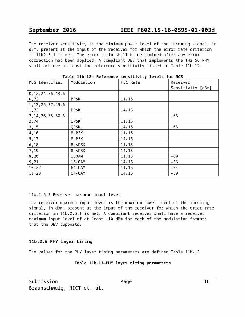
11b.2.5.2 Receiver sensitivityThe receiver sensitivity is the minimum power level of the incoming signal, in dBm, present at the input of the receiver for which the error rate criterion in 11b2.5.1 is met. The error ratio shall be determined after any error correction has been applied. A compliant DEV that implements the THz SC PHY shall achieve at least the reference sensitivity listed in Table 11b-12.
Table 11b-12— Reference sensitivity levels for MCSMCS Identifier Modulation FEC Rate Receiver Sensitivity [dBm]0,12,24,36.48,60,72 BPSK 11/151,13,25,37,49,61,73 BPSK 14/152,14,26,38,50,62,74 QPSK 11/15 -663,15 QPSK 14/15 -634,16 8-PSK 11/155,17 8-PSK 14/156,18 8-APSK 11/157,19 8-APSK 14/158,20 16QAM 11/15 -609,21 16-QAM 14/15 -5610,22 64-QAM 11/15 -5411,23 64-QAM 14/15 -50
11b.2.5.3 Receiver maximum input levelThe receiver maximum input level is the maximum power level of the incoming signal, in dBm, present at the input of the receiver for which the error rate criterion in 11b.2.5.1 is met. A compliant receiver shall have a receiver maximum input level of at least –10 dBm for each of the modulation formats that the DEV supports.
11b.2.6 PHY layer timing
The values for the PHY layer timing parameters are defined Table 11b-13.
Table 11b-13—PHY layer timing parameters
Submission Page TU Braunschweig, NICT et. al.

September 2016 IEEE P802.15-16-0595-01-003d
PHY parameter Value Subclause
pPHYSIFSTime 0.2 μs, 2.0 μs, 2.5 μs (default) 11b.2.6.3
pPHYChannelSwitchTime 100 μs 11b.2.6.5
11b.2.6.1 Interframe spaceA conformant implementation shall support the IFS parameters, as described in 7.4.1, given in Table 11b-14.
Table 11b-14— IFS parameters
MAC parameter Corresponding PHY parameter Definition
MIFS pPHYMIFSTime 12a.2.6.4
SIFS pPHYSIFSTime 12a.2.6.3
pBackoffslot pPHYSIFSTime+pCCADetectTime 11.2.7.1
RIFS 2*pPHYSIFSTime+pCCADetectTime 8.4.1
11b.2.6.2 Receive-to-transmit turnaround timeThe receive to transmit turnaround time shall be pPHYSIFSTime, including the power-up ramp specified in 11b.2.4.4. The receive to transmit turnaround time shall be measured at the air interface from the trailing edge of the last symbol received until the first symbol of the PHY preamble is present at the air interface.
11b.2.6.3 Transmit-to-receive turnaround-timeThe transmit to receive turnaround time shall be less than pPHYSIFSTime, including the power-down rampspecified in 11b.2.4.4.
11b.2.6.4 Time between successive transmissionsThe minimum time between successive transmissions shall be pPHYMIFSTime, including the power-up ramp specified in 11b.2.4 The pPHYMIFSTime shall be measured at the air interface from the trailing edge of the last symbol transmitted until the first symbol of the PHY preamble is present at the air interface.
11b.2.6.5 Channel switchThe channel switch time is defined as the time from the last valid bit is received at the antenna on one channel until the DEV is ready to transmit or receive on a new channel. The channel switch time shall be less than pPHYChannelSwitchTime.
11b.2.7 PHY management for THZ-SC PHY
The PHY PIB comprises the managed objects, attributes, actions, and notifications required to manage the THz-SC PHY layer of a DEV.
11b.2.7.1 Maximum frame size
Submission Page TU Braunschweig, NICT et. al.

September 2016 IEEE P802.15-16-0595-01-003d
The maximum frame length allowed, pMAXFrameBodySize, shall be 1048576 octets. This total includes the MAC subheader and the MAC frame body, but not the PHY preamble, base header, (PHY header, MAC header and HCS). The maximum frame length also does not include the stuff bits.
11b.2.7.2 Maximum transfer unit sizeThe maximum size data frame passed from the upper layers, pMaxTransferUnitSize, shall be 1048572 octets. If security is enabled for the data connection, the upper layers should limit data frames to 524288 octets minus the security overhead as defined in 6.3.4.2, 6.2.8.1.2, or 6.2.8.2.2.
11b.2.7.3 Minimum fragment sizeThe minimum fragment size, pMinFragmentSize, allowed with the THz-SC PHY shall be 4096 octets.
11b.3 THz-OOK PHY
The THz-OOK PHY is designed for cost effective devices that require low power, low complexity and simple design. For applications using this PHY, transmission ranges of a few tens of centimeters are targeted. The THz-OOK PHY supports a single modulation scheme, OOK and a single FEC scheme, RS.
11b3.1 Channelization for THZ-OOK PHYThe possible channels are the same as defined in 11b.1.4. The transmit spectral masks for the THz-OOK PHY are the same as defined in 11b1.5.
11b.3.2 Modulation and Coding
The entire THz-OOK frame shall be modulated with OOK as specified in 11b.3.2.1. The FEC for THz-OOK PHY shall be RS coding as specified in 11b.3.2.2.
11b.3.2. 1 ModulationTHz-OOK frames shall be modulated using OOK. The OOK modulation shall use variable amplitudes to represent the data. As shown in Figure 11b-5, OOK shall be represented by two points in the constellation map. The simplest form of OOK represents a binary '1' with the presence of the signal, and a binary '0' with the absence of it. The normalization factor, KMOD shall be sqrt(2).
Submission Page TU Braunschweig, NICT et. al.

September 2016 IEEE P802.15-16-0595-01-003d
Figure 11b-5 Constellation Diagram for OOK
The actual transmitted RF signal can be written as follows:
SRF(t )= ∑k=0
N chip−1
ak sb(t−kTc )cos (2 π f c t)
whereSRF (t) is the transmitted RF signalTc is the chip durationNchip is the number of transmitted chips in the transmitted OOK PHY framefc is the center frequencyak is a binary value in the transmitted frameSB(t) is the baseband pulse shape
11b.3.2.2 Forward Error CorrectionOnly RS block codes as described in 11a.3.2.6.1 shall be used for THz-OOK PHY
11b.3.2.3 MCS dependent parameters.
Table 11b-15 –– MCS dependent parametersMCS identifier bandwidth
(GHz)Spreading
FactorLSF
FEC rate data rate (Gb/s)w/ PW
data rate (Gb/s)
w/o PW0 2.16 1 224/240 1,64266667 1,437333331 4.32 1 224/240 3,28533333 2,874666672 8.64 1 224/240 6,57066667 5,749333333 12.96 1 224/240 9,856 8,6244 17.28 1 224/240 13,1413333 11,4986667
Submission Page TU Braunschweig, NICT et. al.
September 2016 IEEE P802.15-16-0595-01-003d
5 25.92 1 224/240 19,712 17,2486 51.84 1 224/240 39,424 34,496
The remaining part of clause 11b.3 is for further discussion. Two options are proposed:
- option1: follow the structure of 11a.3 (HRCP-OOK)- option 2: follow largely the structure of 11b.2 (THz-SC PHY)
Submission Page TU Braunschweig, NICT et. al.