vision screener user instruction manual user instruction manual.pdfpreface this instruction manual...
TRANSCRIPT

Vision Screener User Instruction Manual
PrefaceThis Instruction Manual was prepared by TITMUS Optical, Inc. for both first-time
and experienced users of the TITMUSi500 model of the vision screener. This
manual provides basic instructions for both use and troubleshooting procedures.
To ensure the safe operation of the TITMUSi500 Vision Screener, the user should
read the entire instruction manual before operation of the unit. Keep this manual
for future reference.
For the RecordPlease record, Serial Number and Purchase Date in space provided:
Serial No. ____________________ Date of Purchase: _________
Distributor______________________________
Phone________________________________
For questionsPlease contact TITMUS at 800-446-1802 or your local distributor.
NOTE: Due to continual product innovation, specifications in this manual are
subject to change without prior notification.
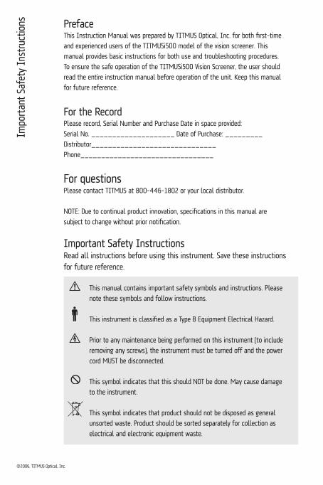
Important Safety InstructionsRead all instructions before using this instrument. Save these instructions for future reference.
This manual contains important safety symbols and instructions. Please
note these symbols and follow instructions.
This instrument is classified as a Type B Equipment Electrical Hazard.
Prior to any maintenance being performed on this instrument (to include
removing any screws), the instrument must be turned off and the power
cord MUST be disconnected.
This symbol indicates that this should NOT be done. May cause damage
to the instrument.
This symbol indicates that product should not be disposed as general
unsorted waste. Product should be sorted separately for collection as
electrical and electronic equipment waste.
Impo
rtan
t Saf
ety
Inst
ruct
ions
©2006, TITMUS Optical, Inc.

Tabl
e of
Con
tent
s
4Warranty & Technical Data 4
4Introduction 5
4TITMUSiSeries Comparison 6
4Standard & Optional Accessories 7
4Unpacking the Instrument 8
4TITMUSi500 External Features — Front & Rear View 10
4TITMUSi500 Touch-Screen Panel 11
4Preparation for Testing 12
4Patient Seating 13
4Height Adjustment 14
4Far Vision Testing 15
4Near Vision Testing 16
4Intermediate Vision Testing & Using Plus Lens 17
4Peripheral Vision Testing 18
4Instrument Transport 18
4Cleaning & Maintenance 19
4Replacing the Fuse 20
4Changing Slides 21
4Replacing Light Module 22
4Electromagnetic Environment — Guidance 23
4Glossary of Eye Care Terms 27
Table of Contents

WarrantyThe TITMUSi500 Vision Screener has a warranty for a period of three (3) years
against defects in materials and workmanship from date of purchase. Warranty
includes the light module.
StandardsThe TITMUS Vision Screener meets the CE, UL, and CSA Standards.
Europe: EN 60601-1-2
Emissions: Group 1, Class A
USA: UL 2601-1, 1st Ed. Category 355
Canada: CSA-C22.2, No. 601.1-M90, Category 245
Class I Device, as per the Canadian Medical
Device Regulations.
Technical DataPower Supply: 110-240 VAC, 0.4A-0.2A, 50/60 Hz
Fuse Rating: 2 A, 250 V, Type – T (time delay)
Cords: 1. Power cord, length 3 meters
Note: Customer must contact TITMUS to obtain
replacement cords or alternate voltage cords (240V).
2. Control panel cord, DIN connector,
length 0.876 meters
3. USB Cable, length 2 meters
Illumination: As per ISO 8596 and ANSI Z80.21 Standards
Dimensions: W X L X H units
12.25 X 16.50 X 12.75 inches (closed condition)
31 X 42 X 32 cm (closed condition)
Weight: 18 lbs / 8 kg
Temperature: +50°F to +100°F (+10°C to +40°C)
Humidity: 30% to 75%
War
rant
y &
Tec
hnic
al D
ata
12.25”
12.7
5”
16.5”
4
The Importance of Vision ScreeningThe eyes are a person’s windows to the world. Without good vision one can
experience a sense of helplessness and may even suffer in other skills necessary
for a full and functional lifestyle.
Utilizing the TITMUSiSeries vision screeners, you will quickly be capable of
assessing whether a person’s vision is within the normal parameters. Visual
abnormalities will be revealed, often motivating action for a referral for further
visual examination and possibly a much-needed visual correction. Consequently,
that person’s quality of life can be enhanced.
The vision screener is capable of testing functions not determined by the typical
“wall” or “eye” chart. Binocularity, muscle balance, color perception, acuity at near
and far, color deficiency, depth perception, and a myriad of other visual functions
can be screened. The wall chart screens for acuity only, leaving many visual
abnormalities unidentified.
About The “TITMUS”TITMUS set the standard for vision screening instruments in 1959 with the
introduction of the OV7 model vision screener. Often referred to as the “TITMUS,”
the older OV7 model as well as the later-generation TITMUS Model 2 are still in
use in many industrial locations, optical practices, as well as schools nationwide.
The screeners are known for their durability.
As the market leader, TITMUS has developed the new TITMUSiSeries of
vision screeners. Designed to meet the unique needs of the 21st century, the
TITMUSiSeries will be a welcome tool because of its convenience, accuracy,
and versatility.In
trod
uctio
n
5

TITMUSiSeriesThe TITMUSiSeries of vision screeners are ergonomically-designed, precision-built
stereoscopic instruments providing precise and prompt measurement of visual
performance. The screeners are engineered for accuracy, validity, and reliability
of the test results, with emphasis on convenience and ease of administration.
The TITMUSiSeries consists of a variety of models.
TITMUSiSeries Model Comparison
This manual covers the following model— TITMUSi500
TITM
USiS
erie
s Co
mpa
rison
6
Model Features i500 i400 i250 i200
•
•••••••
automatic
•optional
•
•
•••••••
automatic
•optional
•
•
••••
•manual
optional
•
•
••••
manual
optional
•
Touch-Screen Control Panel with Software
Membrane Control Panel
Built-In Membrane Switches
Natural Line of Sight Testing
Ergonomics (TitmusComfort™ Height Adjustment)
New Fluorescent Light Source
Portability
Soft Foam Headrest
Head Positioning Sensor
Peripheral Vision Testing
Test Slide Advance/Reverse
Night Vision Testing
Carrying Case (soft-sided)
Standard Accessories
7
Stan
dard
& O
ptio
nal A
cces
sorie
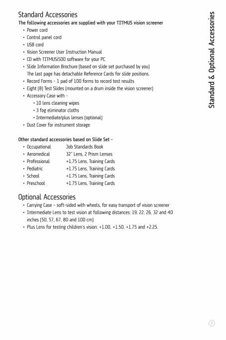
sStandard AccessoriesThe following accessories are supplied with your TITMUS vision screener • Power cord
• Control panel cord
• USB cord
• Vision Screener User Instruction Manual
• CD with TITMUSi500 software for your PC
• Slide Information Brochure (based on slide set purchased by you)
The last page has detachable Reference Cards for slide positions.
• Record Forms – 1 pad of 100 forms to record test results
• Eight (8) Test Slides (mounted on a drum inside the vision screener)
• Accessory Case with –
• 10 lens cleaning wipes
• 3 fog eliminator cloths
• Intermediate/plus lenses (optional)
• Dust Cover for instrument storage
Other standard accessories based on Slide Set - • Occupational Job Standards Book
• Aeromedical 32” Lens, 2 Prism Lenses
• Professional +1.75 Lens, Training Cards
• Pediatric +1.75 Lens, Training Cards
• School +1.75 Lens, Training Cards
• Preschool +1.75 Lens, Training Cards
Optional Accessories • Carrying Case – soft-sided with wheels, for easy transport of vision screener
• Intermediate Lens to test vision at following distances: 19, 22, 26, 32 and 40
inches (50, 57, 67, 80 and 100 cm)
• Plus Lens for testing children’s vision: +1.00, +1.50, +1.75 and +2.25.
Unpa
ckin
g th
e In
stru
men
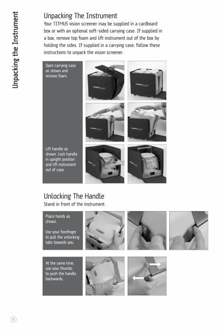
tUnpacking The InstrumentYour TITMUS vision screener may be supplied in a cardboard
box or with an optional soft-sided carrying case. If supplied in
a box, remove top foam and lift instrument out of the box by
holding the sides. If supplied in a carrying case, follow these
instructions to unpack the vision screener.
Unlocking The HandleStand in front of the instrument.
Open carrying case as shown and remove foam.
Lift handle as shown. Lock handle in upright position and lift instrument out of case.
8
Place hands as shown.
Use your forefinger to pull the unlocking tabs towards you.
At the same time, use your thumbs to push the handle backwards.

Unlocking The Bottom Lock
9
Unpa
ckin
g th
e In
stru
men
t
Use one hand to pull the tab outward as shown. AT THE SAME TIME, place your other hand under the ocular housing and lift it upwards.
Lift instrument slightly to remove panel. See tabs to mount panel back.
See tabs (Left/Right) at the back of the instrument. Push tabs inwards. Lift top cover up.
Remove packing foam. Place top cover back on and ensure tabs snap back in place.
Remove Internal Packing Foam (TITMUSi400 only)
LEFT RIGHT
SAVE this foam piece if you will be transporting the vision screener. This MUST be used to prevent damage to the drum assembly during transport.

10
A
B
TITM
USi5
00 E
xter
nal F
eatu
res
– Fr
ont
& R
ear V
iew
Patent Pending
A
B
C
D
E
H
G
F
I
J
K
Rear View
A 4Touch-Screen panelB 4Handle
Front View
A 4 Foldable handle for easy transportB 4 Removable cover for access to slides and light sourceC 4 Lever for far/near lensesD 4 Slots for intermediate/plus lensE 4 Comfortable foam headrestF 4 Head sensor to detect correct positioning
G 4 Vision screening at far (20’) and near (14”)H 4 Handle unlockI 4 Knob to raise and lower the instrumentJ 4 Instrument unlockK 4 Side pocket for storage
Power S
witch
D
C
C 4FuseD 4Power switch
Fuse

11
TITM
USi5
00 T
ouch
-Scr
een
Pane
l
Software on the touch-screenA 4 Navigate Tabs within a MenuB 4 Info about i500 software versionC 4 Navigate Menus up-Main, Results, TestD 4 Navigate Tabs within a Menu
E 4 Navigate Menus down-Main, Test, ResultsF 4 Touch-screen panelG 4 Stylus to operate touch-screen
There are 3 major menus on the TITMUSi500 Software. Navigate the touch screen, using the stylus located in the groove on the control panel AND using the 5-button cluster. Refer to the TITMUSi500 Software Manual for details.
Main MenuThis menu is mainly for log-in, initial set-up and customization. Options on the Main Menu include:
• Language - Select language of operation• Log-in - To start operating the instrument• Slides - To view or customize slide set-up• Sequence - To view or customize testing sequences, 6 preset sequences available• Standards - To view Job Standards, 6 available, cannot be changed • Utilities - To edit User Preferences, add Users/Passwords, edit Sequence Names, Update the TITMUSi500 software, Screener Functions (simulated control panel), Edit Facility Information/Address, View and Edit Date/Time and Adjust LCD Screen Contrast
Test MenuThis menu is accessed most oftern by a user. Options include:
• Subject Data - Enter patient (subject) information• Sequence - Select testing sequence based on patient • Nos. 1-8, P - These are the test screens for each test - displays test information and instructions for each patient, allows to record answers and provides interpretation. These screens cannot be navigated by selecting
the tabs, navigate by selecting “Advance Test” on each test screen.
Results MenuThis menu is mainly used to access test results. Options include:
• Save - To save test results• View - To view test results• Compare - To compare saved results to job standards• Print - Option Currently Not Available• Delete - Delete test results
A
B
E
D
C
G
F

Preparation For Testing1. Place the instrument on a table of conventional height with sufficient top area to permit test administrator to manipulate controls and record results.2. Unlock handle, bottom lock and raise instrument as indicated in section, Unpacking the Instrument.3. Connect panel to instrument as shown using panel cord. Hold the connector with flat side down, to plug into panel and instrument.
4. Connect power cord to instrument and turn switch ON.
5. Test the screener functions from the Utilities Menu on the touch-screen panel, to ensure proper operation. 6. Check lenses to ensure they are clean. Use cleaning towlettes or fog cloths (if lens are fogging).7. Place other accessories near the instrument, ready for use.8. Avoid positioning the instrument where strong glaring light will shine directly into the instrument or into the subject’s face.9. The patient should be seated comfortably. See section on Patient Seating.10. Raise the instrument for comfortable viewing, based on patient height. Move instrument up/down using BOTH knobs. See section on Height Adjustment.11. Ensure lever is in FAR position.
Prep
arat
ion
for T
estin
g
12
TITMUSi400 only Panel cord, length 0.876 meters.
Power cord (3pin length 3 meters).
Lever should point to mountian icon.

13
Patient SeatingPatient must be comfortably seated or standing. Ensure
forehead is placed on headrest. Ensure that back is straight and
neck is not tilted backwards. Do not let patient continue looking
at slide after test is finished. Proceed to next test.
Patie
nt S
eatin
g
Incorrect patient position.
Back is not straight
Neck is tilted. Forehead not placed on headrest.
Correct patient position.
White dot on the knob should match purple dot on label.
12. Turn knob to ensure drum assembly is in FAR position (looking straight ahead). White dot on the knob should match with the purple dot on the label of the knob. See section, Far/Near Vision Testing.
13. Follow the Slide Information Brochure provided with specific model for test sequencing and recording.
14
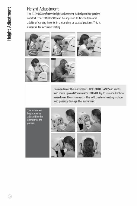
Height AdjustmentThe TITMUSComfort™ height adjustment is designed for patient
comfort. The TITMUSi500 can be adjusted to fit children and
adults of varying heights in a standing or seated position. This is
essential for accurate testing.
The instrument height can be adjusted by the operator or the patient.
To raise/lower the instrument – USE BOTH HANDS on knobs and move upwards/downwards. DO NOT try to use one knob to raise/lower the instrument – this will create a twisting motion and possibly damage the instrument.
Heig
ht A
djus
tmen
t

15
Operating The Far/Near Lever1. Operator is seated on the right or left of the instrument.
2. To move the lever from FAR to NEAR and back. Pull the lever to move
towards you and push it to move away from you. Ensure that lever is
pushed completely to the other end.
Far Vision Testing1. Lever in FAR position, indicated by the “Mountain” Icon, test distance
of 20 feet.
2. Lens assembly should be in FAR position (looking straight ahead).
3. White dot on the knob should match with the purple dot on the label
of the knob.
Ensure that lever is pushed completely to the other end.
Far V
isio
n Te
stin
g
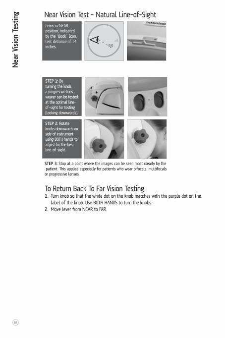
Near Vision Test - Natural Line-of-SightLever in NEAR position, indicated by the “Book” Icon, test distance of 14 inches.
Nea
r Vis
ion
Test
ing
To Return Back To Far Vision Testing1. Turn knob so that the white dot on the knob matches with the purple dot on the label of the knob. Use BOTH HANDS to turn the knobs.2. Move lever from NEAR to FAR.
16
STEP 1: By turning the knob, a progressive lens wearer can be tested at the optimal line-of-sight for testing (looking downwards).
STEP 2: Rotate knobs downwards on side of instrument using BOTH hands to adjust for the best line-of-sight.
STEP 3: Stop at a point where the images can be seen most clearly by the patient. This applies especially for patients who wear bifocals, multifocals or progressive lenses.

Using Plus LensThe plus lens must be inserted in the slot with the label facing the front of the instrument.
See above images.
• The Plus Lens, +1.75 is used with the Acuity test for children. Other plus lenses
are also available as optional accessories.
• Standard testing procedure requires that acuity test is administered first. If child
demonstrates poor visual acuity (20/40), it is unnecessary to administer the
Plus Lens Test. If the child demonstrates 20/30 or 20/20, administer the Plus
Lens Test.
• Children with normal vision will be unable to read the 20/20 line through the Plus
Lens. If a child can read the 20/20 line through the Plus Lens, then result is
FAIL. Blurred vision through Plus Lens is normal, clear distance vision is abnormal
and can indicate excessive farsightedness. This test is very important for school
age children.
17
Inte
rmed
iate
Vis
ion
Test
ing
& U
sing
Plu
s Le
nsIntermediate Vision TestingEnsure lever is in FAR position. Place plus lens in the holder. Perform test. REMOVE lens upon completion of test.
Do not turn the knob while the lens is in the instrument.

18
Instrument transport.
Instrument transport in case
Peripheral Vision TestingRefer to the TITMUSi500 Software Manual for the screen shot and procedure for
peripheral vision testing.
Instrument TransportFollow directions in section Unpacking the Instrument in reverse.
• Disconnect the power cord.
• Disconnect membrane panel and store it at the back of the instrument.
• Ensure the bottom lock is engaged.
Perip
hera
l Vis
ion
Test
ing
& I
nstr
umen
t Tr
ansp
ort

Clea
ning
& M
aint
enan
ce
19
Cleaning the Instrument• See accesory case provided with the instrument. Lens cleaning
towlettes are supplied for cleaning the viewing lenses. Fog
cloths are supplied to prevent the viewing lenses from fogging.
• Soft foam headrest may be repeatedly cleaned using a
disinfectant solution. This practice is recommended between
the testing of each subject.
• The exterior of the instrument may be easily cleaned with a
soft cloth dampened in a mild solution of soap and water.
• Test Slides are in a completely enclosed module, hence
cleaning is rarely required. If required, slides may be cleaned
utilizing a household-type glass cleaner. Remove slides before
cleaning. Do not use abrasives as they will damage the slide.
Do not immerse slide in cleaning solution. Dampen soft cloth
with solution and gently wipe clean. Dry the slides with a soft
cloth or tissue.
Dust CoverUse dust cover to protect the instrument and prevent dust accumulation when not in use.

Repl
acin
g th
e Fu
se Replacing the Fuse
• Tool required: Flat head screwdriver. • A safety feature on the fuse holder will disconnect the power if instrument
is inadvertently left plugged in. Follow the steps in reverse to assemble.
Use screwdriver to snap open the tab on the power module.
Use screwdriver to remove the fuse assembly by pulling it outwards.
Unplug instrument.
Replace both fuses.
20
FIRST UNPLUG THE INSTRUMENT.

Chan
ging
Slid
esChanging Slides
• Tool required: Philips head screwdriver.
STEP 1: Remove top cover by moving tabs at the back.
STEP 2: Remove the 2 screws as indicated. Disconnect connector, if any, on the top of the slide drum assembly.
Lift the slide drum assembly by tilting it upwards, so that the lip on the front is disengaged.
STEP 3: Disconnect the connector on the side of the drum by pushing on the tab in the middle of the connector and pulling it outwards.
STEP 4: Separate the drum from the instrument.
21
FIRST UNPLUG THE INSTRUMENT.

Repl
acin
g Li
ght
Mod
ule
Remove the four screws on the lamp assembly. Pull lamp assembly out. Relace with new lamp assembly.
Changing Slides Cont.
• Insert new slide with the arrow pointing in the proper direction and securely place into slide frame. Slide will snap into place.• Follow instructions in reverse to assemble drum back.
Replacing Light Module
• Tool required: Philips head screwdriverLight module has a life expectancy exceeding 10,000 hours.
To replace, follow steps mentioned below.
Follow steps 1-4 as mentioned in the Changing Slides section.
STEP 5: Roll the rubber ring at the centerof the drum to the side.
STEP 6: Pull on the tab towards the gear side of the drum. This will cause the slide to pop up from one side. Remove and replace with new slide.
22
FIRST UNPLUG THE INSTRUMENT.

23
Elec
trom
agne
tic E
nviro
mne
ntElectromagnetic Environment – GuidanceThis section applies to the following model — TITMUSi500
Medical Electrical Equipment needs special precautions regarding Electromagnetic
Emissions and Immunity and needs to be installed and put into service according to
the Electromagnetic Emissions and Immunity information provided in this document.
Portable and mobile RF communications equipment can affect Medical
Electrical Equipment.
Equipment should not be used adjacent to or stacked with other equipment and if
adjacent or stacked use is necessary, the Equipment should be observed to verify
normal operation in the configuration in which it will be used.
Guidance and Manufacturer’s Declaration - Electromagnetic EmissionThe TITMUSi500 is intended for the use in the electromagnetic environment
specified below. The customer or the user of the TITMUSi500 should ensure that
it is used in such an environment.
Use of cables, other than those specified in this manual, may result in increased
Emissions or decreased Immunity of the TITMUSi500.
Emissons Test Compliance Electromagnetic environment -guidance
RF emissionsCISPR 11
RF emissonsCISPR 11
Harmonic Emissons IEC 61000-3-2
Voltagefluctuations/flicker emissonsIEC 61000-3-3
The TITMUSi500 is suitable for use in all establishments other than domestic and those directly connected to the public low-voltage power supply network that supplies buildings used for domestic purposes.
The TITMUSi500 uses RF energy only for its internal function. Therefore, its RF emissions are very low and are not likely to cause any interference in nearby electronic equipment.
Group 1
Class A
Class A
Complies

Elec
trom
agne
tic E
nviro
mne
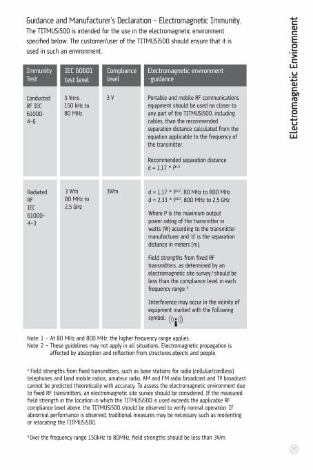
nt Guidance and Manufacturer’s Declaration - Electromagnetic Immunity.The TITMUSi500 is intended for the use in the electromagnetic environment
specified below. The customer/user of the TITMUSi500 should ensure that it is
used in such an environment.
Electrostatic discharge (ESD)IEC 61000-4-2
Electrical fast transient/burstIEC 61000-4-4
SurgeIEC 61000-4-5
Voltage dips, short interruptions and voltage variations on power supply input linesIEC 61000-4-11
Power frequency (50/60 Hz) magnetic fieldIEC 61000-4-8
± 6 kV contact± 8 kV air
± 2 kV for power supply lines± 1 kV for input/output lines
± 1 kV line(s) to line(s)
± 2 kV line(s) to earth
<5 % UT
(>95 % dip in U
T)
for 0,5 cycle
40 % UT
(60 % dip in U
T)
for 5 cycles
70 % UT
(30 % dip in U
T)
for 25 cycles
<5 % UT
(>95 % dip in U
T)
for 5 sec
3 A/m
± 6 kV contact± 8 kV air
± 2 kV for power supply lines± 1 kV for input/output lines
± 1 kV line(s) to line(s)
± 2 kV line(s) to earth
<5 % UT
(>95 % dip in U
T)
for 0,5 cycle
40 % UT
(60 % dip in U
T)
for 5 cycles
70 % UT
(30 % dip in U
T)
for 25 cycles
<5 % UT
(>95 % dip in U
T)
for 5 sec
3 A/m
Floors should be wood, concrete or ceramic tile. If floors are covered with synthetic material, the relative humidity should be at least 30%.
Main power quality should be that of a typical commercial or hospital environment.
Main power quality should be that of a typical commercial or hospital environment.
Main power quality should be that of a typical commercial or hospital environment. If the user of the TITMUSi500 requires continued operation during power main interruptions, it is recommended that the TITMUSi500 be powered from an uninterruptible power supply or a battery.
Power frequency magnetic fields should be at levels characteristic of a typical location in a commercial or hospital environment.
Immunity Test
IEC 60601 test level
Electromagnetic environment -guidance
Compliance level
Note: UT is the a.c. mains voltage prior to application of the test level.24
Elec
trom
agne
tic E
nviro
mne
nt
Conducted RF IEC 61000-4-6
Radiated RFIEC 61000-4-3
3 Vrms150 kHz to 80 MHz
3 V/m80 MHz to 2,5 GHz
3 V
3V/m
Portable and mobile RF communications equipment should be used no closer to any part of the TITMUSi500, including cables, than the recommended separation distance calculated from the equation applicable to the frequency of the transmitter.
Recommended separation distanced = 1,17 * P1/2
d = 1,17 * P1/2, 80 MHz to 800 MHzd = 2,33 * P1/2, 800 MHz to 2,5 GHz
Where P is the maximum output power rating of the transmitter in watts (W) according to the transmitter manufacturer and ‘d’ is the separation distance in meters (m).
Field strengths from fixed RF transmitters, as determined by an electromagnetic site survey,a should be less than the compliance level in each frequency range. b
Interference may occur in the vicinity of equipment marked with the following symbol:
Immunity Test
IEC 60601 test level
Electromagnetic environment -guidance
Compliance level
Guidance and Manufacturer’s Declaration - Electromagnetic Immunity.The TITMUSi500 is intended for the use in the electromagnetic environment
specified below. The customer/user of the TITMUSi500 should ensure that it is
used in such an environment.
Note: 1 — At 80 MHz and 800 MHz, the higher frequency range applies.Note: 2 — These guidelines may not apply in all situations. Electromagnetic propagation is affected by absorption and reflection from structures,objects and people.
a Field strengths from fixed transmitters, such as base stations for radio (cellular/cordless) telephones and land mobile radios, amateur radio, AM and FM radio broadcast and TV broadcast cannot be predicted theoretically with accuracy. To assess the electromagnetic environment due to fixed RF transmitters, an electromagnetic site survey should be considered. If the measured field strength in the location in which the TITMUSi500 is used exceeds the applicable RF compliance level above, the TITMUSi500 should be observed to verify normal operation. If abnormal performance is observed, traditional measures may be necessary such as reorienting or relocating the TITMUSi500.
b Over the frequency range 150kHz to 80MHz, field strengths should be less than 3V/m.
25

Elec
trom
agne
tic E
nviro
mne
nt Recommended separation distance between portable and mobile RF communications equipment and the TITMUSi500The TITMUSi500 is intended for use in the electromagnetic environment in
which radiated RF disturbances are controlled. The customer or the user of the
TITMUSi500 can help prevent electromagnetic interference by maintaining a
minimum distance between portable and mobile RF communication equipment
(transmitters) and the TITMUSi500 as recommended below, according to the
maximum output power of the communications equipment.
For transmitters rated at a maximum output power not listed above, the
recommended separation distance in meters (m) can be estimated using
the equation applicable to the frequency of the transmitter, where P is the
maximum output power rating of the transmitter in watts (W) according to
the transmitter manufacturer.
NOTE 1 — At 80 MHz and 800 MHz, the higher frequency range applies.NOTE 2 — These guidelines may not apply in all situations. Electromagnetic propagation is affected by absorption and reflection from structures, objects and people.
Rated maximum output power of transmitter W
150 kHz to 80 MHzd = 1,17 * P1/2
Separation distance according to frequency of transmitter M
80 MHz to 800 MHzd = 1,17 * P1/2
800 MHz to 2,5 GHzd = 2,33 * P1/2
0,01
0,1
1
10
100
0,12
0,37
1,17
3,70
11,70
0,12
0,37
1,17
3,70
11,70
0,23
0,74
2,33
7,37
23,30
26
AAccommodation – eye’s ability to automatically change focus from seeingat one distance to seeing at another.
Achromatic – being colorless or without color.
Amblyopia – the loss of vision without any apparent cause. Also known as “lazy eye.”
Aphakia – the absence of the crystalline lens either at birth or after surgery.
Astigmatism – condition in which the cornea’s curvature is asymmetrical (the eye is shaped like a football or egg instead of a baseball). Light rays are focused at two points on the retina rather than one, resulting in blurred vision. Additional symptoms include distorted vision, eyestrain, shadows on letters, squinting and double vision.
BBifocals – two powers in one lens, usually for near and distance correction.
Binocular vision – coordinated use of the two eyes.
CCataract – cloudiness or opacity of the crystalline lens, preventing clear vision, often caused by aging.
Color deficiency – inability to recognize certain colors, specifically shades of red and green. Often referred to as “color blindness” and is usually hereditary.
Contact Lens – thin shell of plastic which rests directly on the tear film of the cornea and corrects refractive error.
Convergence – eyes’ ability to turn inward. People with convergence insufficiency have trouble (eyestrain, blurred vision, etc.) with near tasks such as reading.
Cornea – the clear part of the eye covering the iris and pupil; it lets light into the eye, permitting sight.
Crossed eyes – see esotropia.
Crystalline lens – the transparent lens of the eye that brings rays of light into focus on the retina.
DDark adaptation – increase in the sensitivity
of the eye to detect light in the darkness or dim light.
Depth perception – the ability to distinguish the relative distance of objects in visual space.
Diopter – often written as “D.” The unit of measure of lens power. A lens having one diopter of refractive power will bring parallel rays of light to focus at a distance of one meter.
Diplopia – also known as double vision; the perception of two images yet being only one object.
Distance vision – the ability to see objects clearly at 20 ft. to infinity.
Divergence – the slight turning out to adjust the eyes to a distant object.
EEmmetropia – the normal refractive condition of the eye in which there is clear focus of light on the retina.
Esophoria – a muscle condition in which both eyes are open and each eye looks directly at a target, but, when covering one eye, the covered eye turns inwards.
Esotropia – “crossed eyes,” a tendency of the eye to turn inward toward the nose, when both eyes are open.
Exophoria – a muscle condition in which both eyes are open and each eye looks directly at a target, but, when covering one eye, the covered eye turns outwards.
Exotropia – “wall eyes,” this is a tendency of the eye to turn outward, away from the nose, when both eyes are open.
FFar – distance vision.
Farsightedness – see hyperopia.
Field of vision – the entire area which can be seen at one time without shifting the head or the eyes
Fixation – directing the eye so the image centers on the fovea.
Fovea – area of clearest vision on the retina.
Fusion – coordination of the images seen by
Glos
sary
of
Eye
Care
Ter
ms
27

each eye into one picture.
GGlare – bright light which causes discomfort and loss of vision.
Glaucoma – condition caused by increased intraocular pressure which damages the optic nerve.
HHeterophoria – a squint due to a weak muscle.
Hyperopia – also called farsightedness. Condition in which the length of the eye is too short, causing light rays to focus behind the retina rather than on it, resulting in blurred near vision. Additional symptoms include eyestrain and squinting.
Hyperphoria – a tendency for one eye to deviate upward.
Hypophoria – one eye in the line of sight depressed relative to the other eye.
IIntermediate vision — the area of vision between 20 and 40 inches.
Iris – the pigmented area behind the cornea that gives color to the eye (e.g., blue eyes). The cornea controls the amount of light entering the eye by changing the size of the pupil.
LLateral Phoria – a Muscle Balance Test to define a value for the balance of the eyes, in the horizontal direction, that identifies Esophoria, Exophoria, and Orthophoria.
Lazy eye – see amblyopia.
Legal blindness – the best-corrected visual acuity of 20/200 or less.
Lens – 1. the nearly spherical body in the eye, located behind the cornea that focuses light rays onto the retina. 2. a device used to focus light into the eye in order to magnify or minimizes images, or otherwise correct visual problems. Eyeglass lenses, contact lenses, and intraocular lenses are some examples.
MMacula – part of the eye near the middle
of the retina; the macula allows us to see objects with great detail.
Malingering – the intentional production of false symptoms to achieve financial or other gains; for example pretending to have loss of vision to avoid military duty.
Monocular – vision with only one eye.
Muscle balance – the coordination of muscles allowing the two eyes to work together.
Myopia – also called nearsightedness. Condition in which the length of the eye is too long, causing light rays to focus in front of the retina rather than on it, resulting in blurred distance vision. Additional symptoms include eyestrain, poor night vision or squinting.
NNear – vision at 14 to 16 inches.
Nearsightedness – see myopia.
OOcclusion – obstruction or “shutting” of vision from one or both eyes.
Ophthalmologist – a Medical Doctor (M.D.) who specializes in the eye. Ophthalmologists perform eye exams, treat disease, prescribe medication, and perform surgery. They may also write prescriptions for eyeglasses and contact lenses.
Optician – opticians are not doctors, but in some states they must complete training and be licensed. And in some states they can become certified, after special training, to fit contact lenses. Most opticians sell and fit eyeglasses, sunglasses, and specialty eyewear that are made to an optometrist’s or ophthalmologist’s prescription. Many also have equipment on the premises so they can grind lenses and put them in frames without ordering from a lab.
Optometrist – doctors of optometry (O.D.s) examine eyes for both vision and health problems, prescribe glasses, and fit contact lenses. They can prescribe many ophthalmic medications and may participate in your pre- and postoperative care if you have eye surgery. O.D.s must complete four years of post-graduate optometry school for their doctorate.
Orthophoria – ideal condition of muscle balance (balanced eyes).
Glos
sary
of
Eye
Care
Ter
ms
28

PPerimetry – charting the eye’s field of vision, often using light flashed at various locations from the outside peripheral plane to the nasal area.
Peripheral vision – ability to perceive objects outside of the direct line of vision.
Presbyopia – loss of accommodation due to aging (usually after age 40), causing difficulty focusing on near objects. This is caused by the loss of elasticity of the crystalline lens.
Prism – a wedge-shaped piece of glass that can bend rays of light toward its base.
Progressive lens – an eyeglass lens that incorporates both the distance and near vision correction into one lens without a line.
Pupil – the opening in the center of the iris that changes size to regulate the amount of light that enters the eye.
RRefraction – the bending of the rays of light. Sometimes used to refer to an eye examination that determines the best corrective lenses for good vision.
Retina – the multi-layered sensory tissue, lining the back of the eye, that captures and converts light rays into electrical impulses and sends them to the brain where they are converted into images.
SSnellen chart – a chart, often hung on a wall at a distance of 20 ft. from the subject, used for evaluating visual acuity. Symbols or letters and numbers should be legible if eyes are normal.
Strabismus – a manifestation of a muscle imbalance. Eyes that turn inward or outward.
Stereopsis – depth perception; ability to see binocularly (two-eyed).
Suppression – the blocking of vision of one eye without apparent structural or physical cause.
TTonometry – is used to detect glaucoma by measuring of the pressure inside (intraocular) the eye.
Trifocal – corrective lens that incorporates three different lens powers, usually for near,
intermediate, and distance vision correction.
20/20 – many eye care practitioners consider this the average visual acuity for human beings, but humans can see 20/15 or even 20/10. People with 20/40 vision can see clearly at 20 feet what people with 20/20 vision can see clearly at 40 feet. In the United States, 20/40 is the lowest uncorrected acuity required to obtain a driver’s license.
VVertical Phoria – a Muscle Balance Test to define a value for the balance of the eyes in the vertical direction. This identifies a tendency of Hyperphoria (one eye in the line of sight elevated relative to the other eye)
Vision – the ability to see and to interpret what is seen.
Visual acuity — the sharpness of vision of an eye.
Visual field – the full scope of the area that the eye can see while looking straight ahead.
WWall eyes - see exotropia.
Glos
sary
of
Eye
Care
Ter
ms
Many terms in this glossary are used with
permission by www.allaboutvision.com.
Visit website for additional eye care terms.
For additional eye care terms see the
following glossaries and web sites:
Dictionary of Eye Terminology by
Triad Publishing Company
P.O. Box 13355,
Gainesville, Florida 32604
www.triadpublishing.com
OPTOMETRISTS NETWORK
http://www.children-special-needs.org/
http://www.strabismus.org/miscellaneous.html
29

Notes

Notes

An ISO 9001: 2000 Company
3811 Corporate Drive, Petersburg, VA 23805, Tel: 800-446-1802, Fax: 804-861-3957Email: [email protected], Web: www.titmusiseries.com
Item# 18238 / 3.06.PS