visual test extensions
TRANSCRIPT
Visual Test Extensions
U S E R ’ S G U I D E
Visual Test ExtensionsUser’s Guide
Revision C - June 1996Part Number: 81580
TM
New Contact Information
Keithley Instruments, Inc.28775 Aurora Road
Cleveland, OH 44139
Technical Support: 1-888-KEITHLEYMonday – Friday 8:00 a.m. to 5:00 p.m (EST)
Fax: (440) 248-6168
Visit our website at http://www.keithley.com
Keithley MetraByte Division
Keithley Instruments, Inc.
440 Myles Standish Blvd. Taunton, MA 02780
Telephone: (508) 880-3000
●
FAX: (508) 880-0179
The information contained in this manual is believed to be accurate and reliable. However, Keithley Instruments, Inc., assumes no responsibility for its use or for any infringements of patents or other rights of third parties that may result from its use. No license is granted by implication or otherwise under any patent rights of Keithley Instruments, Inc.
KEITHLEY INSTRUMENTS, INC., SHALL NOT BE LIABLE FOR ANY SPECIAL, INCIDENTAL, OR CONSEQUENTIAL DAMAGES RELATED TO THE USE OF THIS PRODUCT. THIS PRODUCT IS NOT DESIGNED WITH COMPONENTS OF A LEVEL OF RELIABILITY SUITABLE FOR USE IN LIFE SUPPORT OR CRITICAL APPLICATIONS.
Refer to your Keithley Instruments license agreement for specific warranty and liability information.
MetraByte, Visual Test Extensions, and VTX are trademarks of Keithley Instruments, Inc. All other brand and product names are trademarks or registered trademarks of their respective companies.
© Copyright Keithley Instruments, Inc., 1995, 1996.
All rights reserved. Reproduction or adaptation of any part of this documentation beyond that permitted by Section 117 of the 1976 United States Copyright Act without permission of the Copyright owner is unlawful.
Overview of this Guide ix
Introducing VTX
Visual Test Extensions
™
(VTX
™
) is a powerful system of software tools that enable you to create high-performance data acquisition, analysis, and graphing applications within the Microsoft
®
Visual Basic
™
for Windows
™
programming environment. VTX software tools include an
integrated
set of custom controls. By using VTX software with Visual Basic, you can
●
Build high-performance Windows measurement systems quickly and easily.
●
Integrate data acquisition, counter/timer, analysis, data display, logic, and graphing functions in the same application.
●
Incorporate any third-party products designed for the Visual Basic environment in your application.
●
Create simple applications using graphical programming or complex applications using graphical and code-based programming.
Overview of this Guide
The
Visual Test Extensions User’s Guide
introduces the VTX system of custom controls. The online help that accompanies the VTX software provides detailed information about the VTX system.
Before using the VTX system, it is strongly recommended that you have an understanding of
●
Microsoft Windows, version 3.1 or higher (including Windows 95)
●
Visual Basic for Windows, version 3.0 or the 16-bit versions of Visual Basic, version 4.0 (Professional and Enterprise Editions). (Note that the Standard Edition of Visual Basic 4.0 does not support 16-bit controls.)
●
Data acquisition principles
●
Data acquisition hardware for which you are writing applications
x Introducing VTX
This guide and the online help for the VTX system are written with the assumption that you understand the fundamental programming techniques of Visual Basic, especially the concept of event-driven programming. In addition, it is assumed that you know the capabilities of your data acquisition boards and the options available. Refer to the documentation for Visual Basic, Windows, and your data acquisition boards for basic information about these products.
This guide contains the following chapters:
●
Chapter 1, Installing VTX Software
, lists the system requirements and explains how to install the VTX software.
●
Chapter 2, Creating Your First VTX Application,
provides a tutorial for quickly creating a simple application using the VTX DAS and Text controls. This chapter also provides information on using the example programs that accompany your VTX software
.
●
Chapter 3, Understanding the VTX System
, explains the fundamental concepts of the VTX system.
●
Chapter 4, Building Complex Applications,
describes in detail how to create a complex data acquisition application with Visual Basic and the VTX system.
Conventions
The VTX system provides two controls that communicate directly with the Keithley MetraByte boards that the controls support, the DAS control and the Counter/Timer (CTM) control. Throughout this user’s guide, references to DAS boards or DAS hardware include all Keithley MetraByte data acquisition hardware that the VTX DAS control currently supports. Similarly, references to CTM boards include all Keithley MetraByte counter/timer boards that the VTX CTM control currently supports. Contact your Keithley MetraByte sales representative for a list of currently supported boards.
References to Windows 3.x in this guide include Windows 3.1 and Windows 3.11 for Workgroups only.
Conventions xi
The illustrations in this guide were created using Visual Basic 3.0 running under Windows 3.1. As appropriate, the accompanying text describes items that differ in Visual Basic 4.0 and in Windows 95.
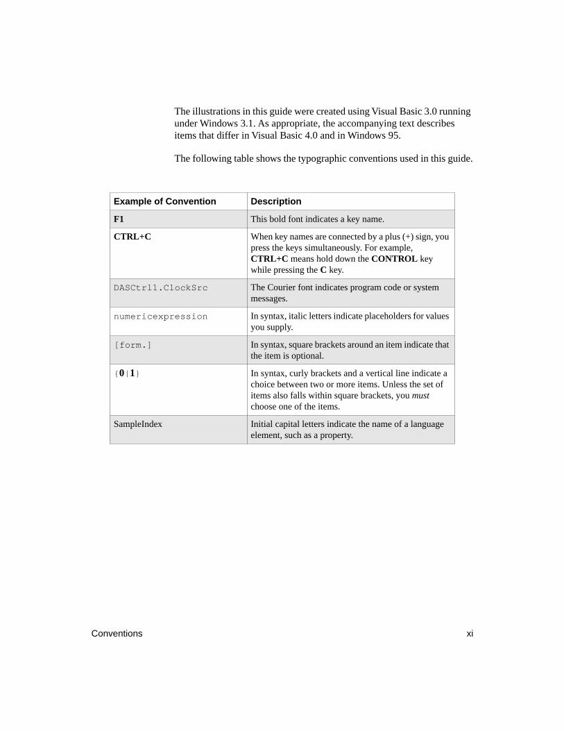
The following table shows the typographic conventions used in this guide.
Example of Convention Description
F1
This bold font indicates a key name.
CTRL+C
When key names are connected by a plus (+) sign, you press the keys simultaneously. For example,
CTRL+C
means hold down the
CONTROL
key while pressing the
C
key.
DASCtrl1.ClockSrc
The Courier font indicates program code or system messages.
numericexpression
In syntax, italic letters indicate placeholders for values you supply.
[form.]
In syntax, square brackets around an item indicate that the item is optional.
{
0
|
1
}
In syntax, curly brackets and a vertical line indicate a choice between two or more items. Unless the set of items also falls within square brackets, you
must
choose one of the items.
SampleIndex Initial capital letters indicate the name of a language element, such as a property.
xii Introducing VTX
Using Online Help
The online help system for the VTX software includes
●
Overview information on the VTX system and on each VTX control
●
Generalized procedures for setting up processes for each VTX control
●
Brief descriptions of the VTX example programs
●
Programming tips
●
Definitions of VTX properties, functions, and events
●
Valid ranges or values for properties
●
Code examples that you can cut and paste into your application
●
Error information
The VTX help system has a general overview help file from which you can access information on all VTX controls and the example programs. In addition, the help system contains a separate help file for each VTX control. All of these help files are installed by default.
To provide specific information for the different Keithley MetraByte boards supported by the VTX software, the VTX help system also contains board-specific help files. When installing the board-specific software, the VTX installation program copies the associated board-specific help file to your hard drive.
The VTX installation program copies VTX help files and their supporting executable files into the same directory. To be able to access the help files from one another, you must keep all of these files in the same directory.
Using Online Help xiii
Accessing VTX Online Help
You can access VTX online help from within Visual Basic and from the Keithley VTX program group created at installation. The methods to access help from Visual Basic are the same under Visual Basic 3.0 and 4.0. In addition, accessing help from either version of Visual Basic is essentially the same under Windows 3.x and Windows 95. The following sections describe ways to access VTX help from Visual Basic, the Keithley VTX program group in Windows 3.x, and the Windows 95 desktop.
From Visual Basic
Use one of the following methods to access VTX online help from within Visual Basic:
●
From the Visual Basic Toolbox, double-click the icon for a VTX control to place the control on a Visual Basic form. With the control still selected on the form, press
F1
. Under Windows 3.x, the main menu (contents) for the control help is displayed. Under Windows 95, the Help Topics dialog box appears with the Contents tab displayed.
●
Display the Properties window or More Properties window of a VTX control. Highlight a property and then press
F1
to display the help topic for that property.
Note that the Properties window for each VTX control contains properties that are standard Visual Basic properties, such as Caption and Name. When you press
F1
on these properties, the standard Visual Basic online help appears.
From the Keithley VTX Program Group in Windows 3.x
The Keithley VTX program group is created when you install VTX software. It includes two help icons (yellow question marks), one captioned VTX Help, and the other captioned Examples. The VTX Help icon lets you access the VTX overview help file. From the main menu (Windows 3.x) of the overview help file, you can access the entire VTX help system, including the Examples help file. The Examples icon provides direct access to the descriptions of the example programs provided with the VTX software.
xiv Introducing VTX
To access general information about the VTX system or specific information about the controls, follow these steps:
1. Double-click the VTX Help icon to display the main menu (Windows 3.x) for the VTX overview help file.
2. From the main menu, double-click the icon or text for the topic you are interested in. Alternatively, click the Search button in the button bar to use the Search keyword list to locate a topic.
From the Windows 95 Desktop
One way to access VTX help from the Windows 95 desktop is to begin with the task bar, as follows:
1. From the Windows 95 task bar, use the left mouse button to click the Start button.
2. From the Start menu, move the mouse pointer over the Programs item.
3. From the Programs menu, move the mouse pointer over the Keithley VTX item.
4. From the Keithley VTX menu, click VTX Help. The Contents tab for the VTX overview help file appears.
If you are accustomed to the Windows 3.x Program Manager and program groups, you may want to use the Windows 95 equivalent, as follows:
1. From the Windows 95 task bar, use the
right
mouse button to click the Start button.
2. When the popup menu appears, click Open.
3. From the Start window, double-click the Programs icon to display the Programs window.
4. Double-click the Keithley VTX icon.
5. From the Keithley VTX program window, double-click the yellow question mark icon for the help file you want to read (VTX Help or Examples).
To access VTX help from the My Computer folder, follow these steps:
1. From the Windows 95 desktop, double-click the My Computer folder to open it.
Using Online Help xv
2. From the My Computer window, double-click the icon of the drive on which you installed VTX software. For example, if you installed VTX software on the C drive, click the C drive icon.
3. From the drive window, double-click the Keithley VTX folder to display the program group window. (If you installed VTX software in the default directory, the folder appears at the root level of the drive. However, if you installed the VTX software elsewhere, you may need to open another folder.)
4. To access the VTX help from the Keithley VTX window, double-click the yellow question mark icon for the help file you want to read (VTX Help or Examples).
Once within the VTX help system, you can access general information about the VTX system or specific information about the controls by following these steps:
1. If necessary, click the Contents button in the button bar near the top of the help window to display the Contents tab of the Help Topics dialog box.
2. From the Contents tab, double-click a book icon to display the topics available.
3. As needed, double-click other book icons until you see the topic you want to read (a page icon).
4. Double-click the page icon to display the topic you want to read.
Alternatively, you can click the Index button in button bar near the top of the help window and use the Index tab of the Help Topics dialog box to search for topics associated with a particular keyword. Note that each tab of the Help Topics dialog box provides a system-wide view of VTX help.
Accessing Board-Specific Information
Windows help provides a button bar near the top of the window that contains standard buttons such as Contents. To let you access information specific to the DAS-Demo Device and to supported Keithley MetraByte board families (for example, the DAS-1800 Series family), the VTX DAS control help file provides two additional buttons:
●
Select Board — Displays a dialog box in which you select the DAS-Demo Device or the Keithley MetraByte board family for
xvi Introducing VTX
which you want additional information. After selecting the family, you must click the Board Specifics button to display the parallel topic in the board-specific help file.
●
Board Specifics — Displays a corresponding topic for the selected board family. For example, from the DAS control topic OpMode Property, you can display the same topic for the DAS-1800 Series family, which shows which operation modes are available for all boards in the DAS-1800 Series family.
To return to the DAS control help topics, the board-specific help files provide two buttons:
●
Back to DAS — Returns to the topic from which you jumped in the VTX DAS control help. For example, from the OpMode Property topic in the DAS control help, you accessed the same topic for the DAS-1600 Series family. From that topic, you browsed forward to the topic, Samples Property. To return to the OpMode Property topic in the DAS control help, click the Back to DAS button.
●
Up to DAS — Displays a corresponding topic in the DAS control help. This button performs the same function as the Board Specifics button, in reverse. For example, you have been browsing in the topics for the DAS-Demo Device and are reading the Samples Property topic. To view the Samples Property topic in the DAS control help, click the Up to DAS button.
The online help system for VTX controls is always available at design time. By default, the help system is also available from the VTX dialog boxes that present warnings and errors at run time. You can use the VTX Options window of the VTX Configuration utility to disable the dialog boxes and/or to disable access to the help system. See “Enabling and Disabling VTX Options” on page 4-41 for details.
If your application will be used by others, you may want to add your own help system and a Help button using the Windows applications programming interface (API) function WINHELP. See your Visual Basic documentation for information on using the WINHELP function.
Getting Additional Help xvii
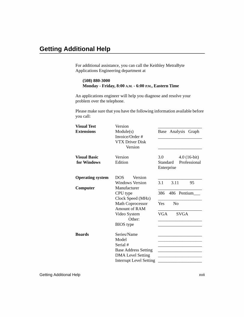
Getting Additional Help
For additional assistance, you can call the Keithley MetraByte Applications Engineering department at
(508) 880-3000Monday - Friday, 8:00
A.M.
- 6:00
P.M.
, Eastern Time
An applications engineer will help you diagnose and resolve your problem over the telephone.
Please make sure that you have the following information available before you call:
Visual Test
Version ____________________
Extensions
Module(s) Base Analysis GraphInvoice/Order # ____________________VTX Driver Disk Version ____________________
Visual Basic
Version 3.0 4.0 (16-bit)
for Windows
Edition Standard ProfessionalEnterprise
Operating system
DOS Version ____________________Windows Version 3.1 3.11 95
Computer
Manufacturer ____________________CPU type 386 486 Pentium___Clock Speed (MHz) ____________________Math Coprocessor Yes NoAmount of RAM ____________________Video System VGA SVGA Other: ____________________BIOS type ____________________
Boards
Series/Name ____________________Model ____________________Serial # ____________________Base Address Setting ____________________DMA Level Setting ____________________Interrupt Level Setting ____________________
xviii Introducing VTX
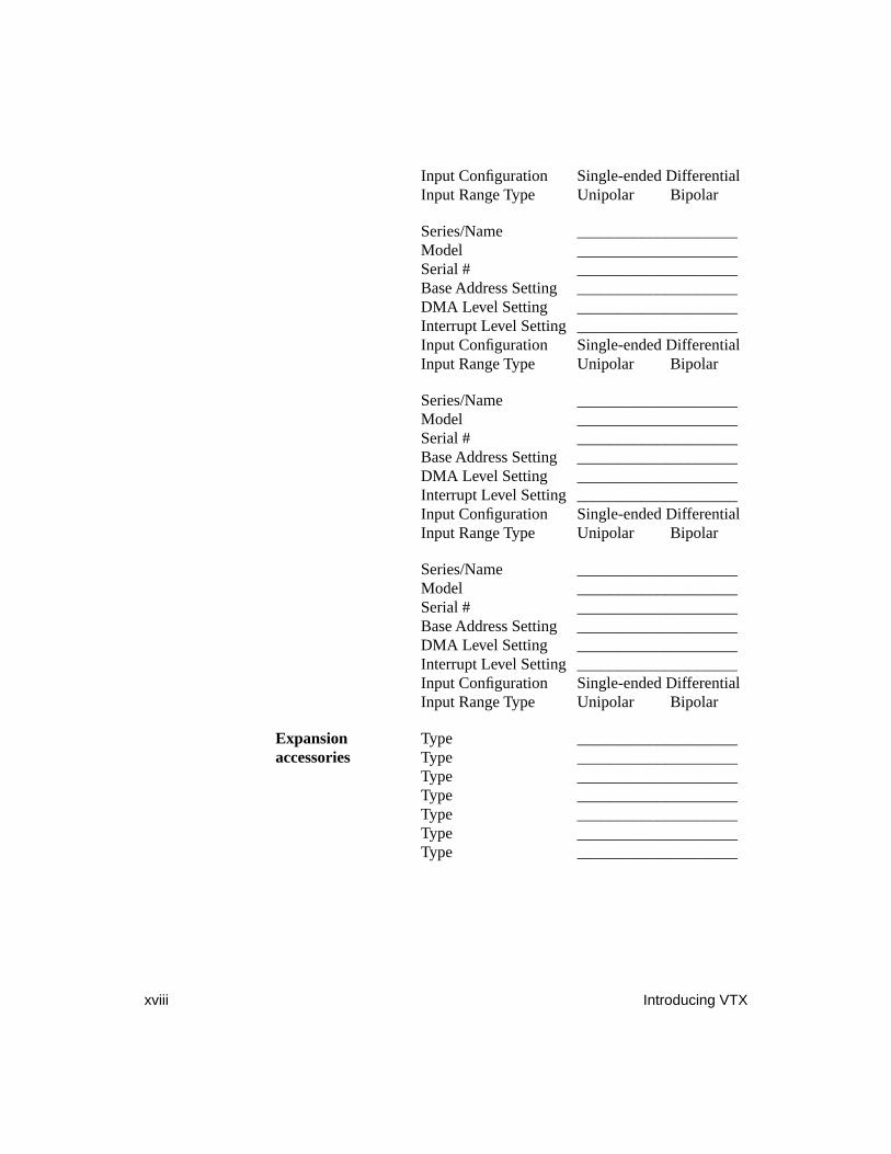
Input Configuration Single-ended DifferentialInput Range Type Unipolar Bipolar
Series/Name ____________________Model ____________________Serial # ____________________Base Address Setting ____________________DMA Level Setting ____________________Interrupt Level Setting ____________________Input Configuration Single-ended DifferentialInput Range Type Unipolar Bipolar
Series/Name ____________________Model ____________________Serial # ____________________Base Address Setting ____________________DMA Level Setting ____________________Interrupt Level Setting ____________________Input Configuration Single-ended DifferentialInput Range Type Unipolar Bipolar
Series/Name ____________________Model ____________________Serial # ____________________Base Address Setting ____________________DMA Level Setting ____________________Interrupt Level Setting ____________________Input Configuration Single-ended DifferentialInput Range Type Unipolar Bipolar
Expansion
Type ____________________
accessories
Type ____________________Type ____________________Type ____________________Type ____________________Type ____________________Type ____________________
Table of Contents
iii
Introducing VTX
Overview of this Guide . . . . . . . . . . . . . . . . . . . . . . . . . . . . . . . . . ixConventions . . . . . . . . . . . . . . . . . . . . . . . . . . . . . . . . . . . . . . . . . . xiUsing Online Help . . . . . . . . . . . . . . . . . . . . . . . . . . . . . . . . . . . . xii
Accessing VTX Online Help. . . . . . . . . . . . . . . . . . . . . . . . . .xiiiFrom Visual Basic . . . . . . . . . . . . . . . . . . . . . . . . . . . . . . .xiiiFrom the Keithley VTX Program Group in Windows 3.x. . . . . . . . . . . . . . . . . . . . . . . . . . . . . . . . . . . .xiiiFrom the Windows 95 Desktop . . . . . . . . . . . . . . . . . . . . . xiv
Accessing Board-Specific Information . . . . . . . . . . . . . . . . . . xvGetting Additional Help . . . . . . . . . . . . . . . . . . . . . . . . . . . . . . . xvii
1
Installing VTX Software
Preparing to Install VTX Software. . . . . . . . . . . . . . . . . . . . . . . .1-1Checking System Requirements . . . . . . . . . . . . . . . . . . . . . . .1-2Checking the Package . . . . . . . . . . . . . . . . . . . . . . . . . . . . . . .1-3Backing Up the Master Disks . . . . . . . . . . . . . . . . . . . . . . . . .1-4
Installing VTX Software . . . . . . . . . . . . . . . . . . . . . . . . . . . . . . .1-4Preparing to Use Boards with VTX Software . . . . . . . . . . . . . . .1-6
Registering and Configuring Boards . . . . . . . . . . . . . . . . . . . .1-7Changing the Configuration of a Registered Board . . . . .1-10Deleting a Registered Board. . . . . . . . . . . . . . . . . . . . . . .1-10Changing an Alias . . . . . . . . . . . . . . . . . . . . . . . . . . . . . .1-11Specifying Engineering Units . . . . . . . . . . . . . . . . . . . . .1-12
Reserving Memory . . . . . . . . . . . . . . . . . . . . . . . . . . . . . . . .1-15Installing Hardware. . . . . . . . . . . . . . . . . . . . . . . . . . . . . . . .1-17
Loading VTX Controls. . . . . . . . . . . . . . . . . . . . . . . . . . . . . . . .1-18Adding a Control to an Application Manually . . . . . . . . . . .1-19
Visual Basic 3.0 . . . . . . . . . . . . . . . . . . . . . . . . . . . . . . . .1-20Visual Basic 4.0 . . . . . . . . . . . . . . . . . . . . . . . . . . . . . . . .1-20
Loading VTX Controls Automatically . . . . . . . . . . . . . . . . .1-21Visual Basic 3.0 . . . . . . . . . . . . . . . . . . . . . . . . . . . . . . . .1-22Visual Basic 4.0 . . . . . . . . . . . . . . . . . . . . . . . . . . . . . . . .1-23
Creating Your First VTX Application . . . . . . . . . . . . . . . . . . . .1-24
iv
2
Creating Your First VTX Application
Assumptions. . . . . . . . . . . . . . . . . . . . . . . . . . . . . . . . . . . . . . . . .2-1Overview of the Application . . . . . . . . . . . . . . . . . . . . . . . . . . . .2-2Design the User Interface. . . . . . . . . . . . . . . . . . . . . . . . . . . . . . .2-3Set the Properties . . . . . . . . . . . . . . . . . . . . . . . . . . . . . . . . . . . . .2-9
Set the Form Properties . . . . . . . . . . . . . . . . . . . . . . . . . . . . . .2-9Set the DAS Control Properties. . . . . . . . . . . . . . . . . . . . . . .2-11Set the Text Control Properties . . . . . . . . . . . . . . . . . . . . . . .2-14Set the Command Button Properties . . . . . . . . . . . . . . . . . . .2-16
Connect the VTX Controls. . . . . . . . . . . . . . . . . . . . . . . . . . . . .2-22Write the Code . . . . . . . . . . . . . . . . . . . . . . . . . . . . . . . . . . . . . .2-24
Write Code for the Start Button . . . . . . . . . . . . . . . . . . . . . .2-25Write Code for the Stop Button . . . . . . . . . . . . . . . . . . . . . .2-27Write Code for the Exit Button . . . . . . . . . . . . . . . . . . . . . . .2-28
Run the Application . . . . . . . . . . . . . . . . . . . . . . . . . . . . . . . . . .2-30What’s Next . . . . . . . . . . . . . . . . . . . . . . . . . . . . . . . . . . . . . . . .2-31
3
Understanding the VTX System
The VTX Environment. . . . . . . . . . . . . . . . . . . . . . . . . . . . . . . . .3-1Processes and Process Sources . . . . . . . . . . . . . . . . . . . . . . . . . .3-3Overview of VTX Tools . . . . . . . . . . . . . . . . . . . . . . . . . . . . . . . .3-5Properties of VTX Controls . . . . . . . . . . . . . . . . . . . . . . . . . . . . .3-8
Control Properties . . . . . . . . . . . . . . . . . . . . . . . . . . . . . . . . . .3-8Operation-Specific Properties . . . . . . . . . . . . . . . . . . . . . . . .3-11
Source and Destination Controls . . . . . . . . . . . . . . . . . . . . . . . .3-14Program Control in the VTX Environment . . . . . . . . . . . . . .3-16Data in the VTX Environment . . . . . . . . . . . . . . . . . . . . . . .3-16
Defining the Structure of Data in the VTX Environment . . . . . . . . . . . . . . . . . . . . . . . . . . . . . .3-17Moving Data between VTX Controls. . . . . . . . . . . . . . . .3-18Moving Data to and from the VTX Environment . . . . . .3-19
Connections . . . . . . . . . . . . . . . . . . . . . . . . . . . . . . . . . . . . . . . .3-20Connection Types . . . . . . . . . . . . . . . . . . . . . . . . . . . . . . . . .3-21Connection Points . . . . . . . . . . . . . . . . . . . . . . . . . . . . . . . . .3-22Multiple Connections . . . . . . . . . . . . . . . . . . . . . . . . . . . . . .3-25Interform Connections . . . . . . . . . . . . . . . . . . . . . . . . . . . . .3-26
Concept Summary . . . . . . . . . . . . . . . . . . . . . . . . . . . . . . . . . . .3-30
v
4
Building Complex Applications
Planning the Application . . . . . . . . . . . . . . . . . . . . . . . . . . . . . . .4-2Designing the User Interface . . . . . . . . . . . . . . . . . . . . . . . . . . . .4-3Setting Properties . . . . . . . . . . . . . . . . . . . . . . . . . . . . . . . . . . . . .4-5Connecting VTX Controls . . . . . . . . . . . . . . . . . . . . . . . . . . . . . .4-6
Displaying the Order of Multiple Connections. . . . . . . . . . . .4-7Changing the Order of Multiple Connections. . . . . . . . . . . . .4-8Drawing Interform Connections . . . . . . . . . . . . . . . . . . . . . . .4-9Deleting Connections . . . . . . . . . . . . . . . . . . . . . . . . . . . . . .4-11
Writing Code . . . . . . . . . . . . . . . . . . . . . . . . . . . . . . . . . . . . . . .4-12VTX Events. . . . . . . . . . . . . . . . . . . . . . . . . . . . . . . . . . . . . .4-13
ProcessDone Event. . . . . . . . . . . . . . . . . . . . . . . . . . . . . .4-14ProcessError Event . . . . . . . . . . . . . . . . . . . . . . . . . . . . . .4-15ProcessCTMDone Event . . . . . . . . . . . . . . . . . . . . . . . . .4-15NDataDone Event. . . . . . . . . . . . . . . . . . . . . . . . . . . . . . .4-16Text Control Events . . . . . . . . . . . . . . . . . . . . . . . . . . . . .4-16
VTX Functions . . . . . . . . . . . . . . . . . . . . . . . . . . . . . . . . . . .4-17Integration of the User Interface and Supporting Tasks . . . .4-19
Accepting User Input . . . . . . . . . . . . . . . . . . . . . . . . . . . .4-21Starting/Stopping Operations . . . . . . . . . . . . . . . . . . . . . .4-24
Click Event Procedure - Starting VTX Controls . . . . .4-25Click Event Procedure - Stopping VTX Controls . . . .4-25
Displaying Status . . . . . . . . . . . . . . . . . . . . . . . . . . . . . . .4-27Displaying Data . . . . . . . . . . . . . . . . . . . . . . . . . . . . . . . .4-27
Displaying a Scalar . . . . . . . . . . . . . . . . . . . . . . . . . . .4-28Displaying Data in a VTX Grid. . . . . . . . . . . . . . . . . .4-29Graphing Data . . . . . . . . . . . . . . . . . . . . . . . . . . . . . . .4-33Displaying Data in a List Box . . . . . . . . . . . . . . . . . . .4-34Displaying Data in a Windows Spreadsheet . . . . . . . .4-35
Error Handling . . . . . . . . . . . . . . . . . . . . . . . . . . . . . . . . . . .4-36Execution Errors. . . . . . . . . . . . . . . . . . . . . . . . . . . . . . . .4-37Process Warnings and Errors . . . . . . . . . . . . . . . . . . . . . .4-38
Testing, Debugging, and Preparing for Distribution . . . . . . . . .4-39Using Visual Basic Debugging Tools with VTX Controls . . . . . . . . . . . . . . . . . . . . . . . . . . . . . . . . . . . .4-40Enabling and Disabling VTX Options . . . . . . . . . . . . . . . . .4-41Selecting Files for Distribution . . . . . . . . . . . . . . . . . . . . . . .4-42
Board-Specific Files . . . . . . . . . . . . . . . . . . . . . . . . . . . . .4-43INI Files . . . . . . . . . . . . . . . . . . . . . . . . . . . . . . . . . . . . . .4-44VDMAD.386 File (Windows 3.x) . . . . . . . . . . . . . . . . . .4-45
VTX Software Already Installed. . . . . . . . . . . . . . . . .4-45VTX Software Not Installed . . . . . . . . . . . . . . . . . . . .4-46
vi
VDMAD.VXD File (Windows 95) . . . . . . . . . . . . . . . . .4-47VTX Software Already Installed. . . . . . . . . . . . . . . . .4-47VTX Software Not Installed . . . . . . . . . . . . . . . . . . . .4-47
Index
List of Figures
Figure 1-1. DAS Hardware Configuration Window . . . . . . . .1-8Figure 1-2. List of Aliases . . . . . . . . . . . . . . . . . . . . . . . . . . .1-11Figure 1-3. Engineering Units Window . . . . . . . . . . . . . . . . .1-13Figure 1-4. Keithley Memory Manager Window
(Windows 3.x Version). . . . . . . . . . . . . . . . . . . .1-16Figure 2-1. Displaying a Single Data Point -
Design-Time View. . . . . . . . . . . . . . . . . . . . . . . . .2-2Figure 2-2. Displaying a Single Data Point -
Run-Time View . . . . . . . . . . . . . . . . . . . . . . . . . . .2-3Figure 3-1. Properties Window for the DAS Control
(Visual Basic 3.0) . . . . . . . . . . . . . . . . . . . . . . . . .3-9Figure 3-2. More Properties Window for the DAS Control . .3-11Figure 3-3. Effects of Changing the Process Source
on the More Properties Window . . . . . . . . . . . . .3-12Figure 3-4. Effects of Changing Property Values
in the More Properties Window. . . . . . . . . . . . . .3-13Figure 3-5. Source and Destination Controls . . . . . . . . . . . . .3-14Figure 3-6. Multiple Source Controls to a Single
Destination Control . . . . . . . . . . . . . . . . . . . . . . .3-15Figure 3-7. Example of a Data Group in the
VTX Environment . . . . . . . . . . . . . . . . . . . . . . . .3-17Figure 3-8. Example of Moving Data to and from the
VTX Environment . . . . . . . . . . . . . . . . . . . . . . . .3-19Figure 3-9. Types of Connections . . . . . . . . . . . . . . . . . . . . .3-21Figure 3-10. Examples of Connection Points. . . . . . . . . . . . . .3-23Figure 3-11. VTX Logic Control Connection Points . . . . . . . .3-24Figure 3-12. Data, CTM, and Computation Control
Output Connection Points . . . . . . . . . . . . . . . . . .3-25Figure 3-13. Multiple Connections to the Same
Connection Point . . . . . . . . . . . . . . . . . . . . . . . . .3-26Figure 3-14. Example of Interform Connections . . . . . . . . . . .3-27Figure 3-15. Using Separate Forms and Interform
Connections . . . . . . . . . . . . . . . . . . . . . . . . . . . . .3-28
vii
Figure 3-16. Example of the Interform Connection Dialog Box. . . . . . . . . . . . . . . . . . . . . . . . . . . . . .3-29
Figure 4-1. Using Separate Forms for a Complex VTX Application . . . . . . . . . . . . . . . . . . . . . . . . . .4-3
Figure 4-2. Multiple Connections to the Same Input Connection Point . . . . . . . . . . . . . . . . . . . . .4-7
Figure 4-3. Changing the Order of Connections . . . . . . . . . . .4-8Figure 4-4. Interform Connection Example . . . . . . . . . . . . . .4-10Figure 4-5. Selecting Connections for Deletion . . . . . . . . . . .4-12Figure 4-6. VTX DAS Example 3 . . . . . . . . . . . . . . . . . . . . .4-20Figure 4-7. Displaying a Single Data Point -
Design-Time View. . . . . . . . . . . . . . . . . . . . . . . .4-28Figure 4-8. Displaying a Single Data Point -
Run-Time View . . . . . . . . . . . . . . . . . . . . . . . . . .4-29Figure 4-9. Displaying Data in a Grid -
Design-Time View. . . . . . . . . . . . . . . . . . . . . . . .4-30Figure 4-10. Displaying Data in a Grid - Run-Time View. . . .4-31Figure 4-11. Graphing Data . . . . . . . . . . . . . . . . . . . . . . . . . . .4-33Figure 4-12. Displaying Data in a Visual Basic List Box . . . .4-34Figure 4-13. Transferring Data to a Spreadsheet . . . . . . . . . . .4-36
List of Tables
Table 1-1. Backup Commands . . . . . . . . . . . . . . . . . . . . . . . .1-4Table 1-2. VTX Control Filenames. . . . . . . . . . . . . . . . . . . .1-18Table 3-1. VTX Controls, Processes, and Process
Sources. . . . . . . . . . . . . . . . . . . . . . . . . . . . . . . . . .3-4Table 3-2. Properties Common to all VTX Controls . . . . . .3-10Table 4-1. Visual Basic Events for Text Control
Processes . . . . . . . . . . . . . . . . . . . . . . . . . . . . . . .4-17Table 4-2. Files Required for Distributing VTX
Applications . . . . . . . . . . . . . . . . . . . . . . . . . . . . .4-42
Preparing to Install VTX Software 1-1
1
Installing VTX Software
To get started quickly with the Visual Test Extensions (VTX) system, this chapter explains the steps necessary to install the VTX software. These steps include
1. Preparing for installation.
2. Installing VTX software.
3. Preparing to use boards with VTX software.
4. Loading the VTX controls into the Visual Basic Toolbox (if you have not chosen to load them during installation).
5. Creating your first VTX application.
Note:
The master disk #1 of the VTX DAS Base Module provides an uncompressed text file (INSTALL.TXT) that also explains how to install the VTX software. If you are upgrading your VTX software, check this file for pertinent information before installing the upgrade software. You
can read INSTALL.TXT with any text editor.
Preparing to Install VTX Software
Before you install the VTX software, you need to
1. Check that the system on which you are installing the VTX software meets the system requirements.
2. Check the contents of your VTX package.
3. Make backup copies of the master disks.

1-2 Installing VTX Software
Note:
The VTX software provides a board simulation tool, called the DAS-Demo Device. You can use the DAS-Demo Device to develop applications without installing your Keithley MetraByte board and related
software.
The following subsections describe each of these steps in more detail.
Checking System Requirements
To use the VTX system, ensure that the computer on which you are installing the software meets the following hardware and software requirements:
●
IBM
®
-compatible computer with an 80386DX or higher processor
●
Data acquisition boards available or installed
●
A 3 1/2-inch floppy drive
●
VGA, SVGA, or compatible monitor
●
A mouse and supporting software
●
MS-DOS
®
, version 5.0 or higher
●
Windows, version 3.1 or higher, in standard or enhanced mode, or Windows 95
●
Visual Basic for Windows, version 3.0 (Standard or Professional Editions) or Visual Basic for Windows, version 4.0 (16-bit versions of the Professional and Enterprise Editions only). The Standard Edition of Visual Basic 4.0 does not support 16-bit controls.
Ensure that the computer has memory and hard disk space that are sufficient to support the data acquisition boards, your version of Windows, and Visual Basic for Windows in addition to the VTX system files.
Preparing to Install VTX Software 1-3
Checking the Package
The basic VTX package contains
●
VTX DAS Base Module master disks (3)
●
VTX Driver master disk (1)
●
This guide,
Visual Test Extensions User’s Guide
The VTX DAS Base Module master disks contain the basic VTX software, including the CTM, DAS, Data, Logic, Text, and Transfer control software and VTX system software. The VTX Driver master disk contains the board-specific software (drivers) required to use the VTX software with Keithley MetraByte hardware. See “Installing VTX Software,” on page 1-4 for details on installing the appropriate drivers for your board.
Note:
If you purchase a Keithley MetraByte board that became available after the current version of the VTX software, use the VTX Driver disk
that accompanies the board to install the VTX driver for that board.
The optional VTX modules contain
●
VTX Analysis Module master disk (1)
●
VTX Graph Module master disk (1)
If any disk is missing, call the Keithley MetraByte Applications Engineering department. See “Getting Additional Help,” on page xvii.
1-4 Installing VTX Software
Backing Up the Master Disks
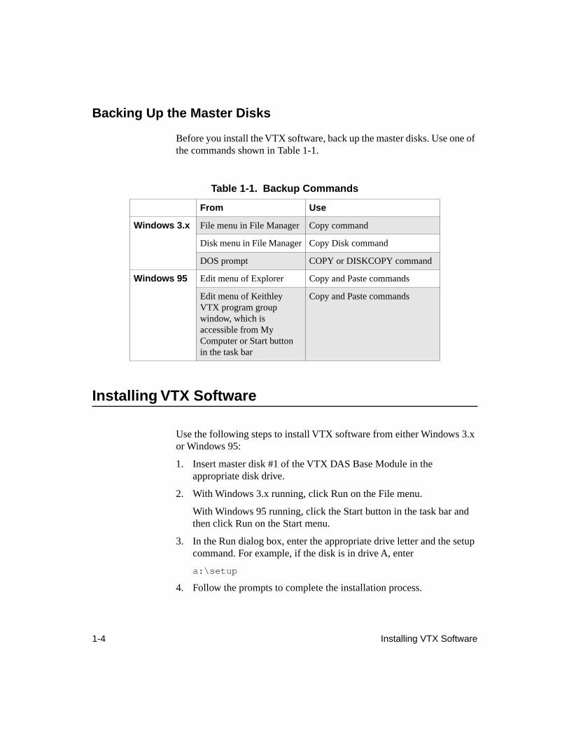
Before you install the VTX software, back up the master disks. Use one of the commands shown in Table 1-1.
Installing VTX Software
Use the following steps to install VTX software from either Windows 3.x or Windows 95:
1. Insert master disk #1 of the VTX DAS Base Module in the appropriate disk drive.
2. With Windows 3.x running, click Run on the File menu.
With Windows 95 running, click the Start button in the task bar and then click Run on the Start menu.
3. In the Run dialog box, enter the appropriate drive letter and the setup command. For example, if the disk is in drive A, enter
a:\setup
4. Follow the prompts to complete the installation process.
Table 1-1. Backup Commands
From Use
Windows 3.x
File menu in File Manager Copy command
Disk menu in File Manager Copy Disk command
DOS prompt COPY or DISKCOPY command
Windows 95
Edit menu of Explorer Copy and Paste commands
Edit menu of Keithley VTX program group window, which is accessible from My Computer or Start button in the task bar
Copy and Paste commands
Installing VTX Software 1-5
The installation program checks for the board-specific software required to use the VTX software with your Keithley MetraByte hardware. If the board-specific software requires an upgrade or is not installed on your computer, the installation program provides the option of upgrading or installing the board-specific software.
If you choose not to upgrade or install the board-specific software at this time, you can run the VTX installation program again at your convenience. When you run the program again, choose the option to customize the installation. At the Custom Installation dialog box, choose only the board-specific software option (deselect all other options). Follow the prompts to upgrade or install the board-specific software.
5. If it successfully locates Visual Basic, the installation program gives you the option of automatically adding the VTX controls to your Visual Basic Toolbox through the AUTOLOAD.MAK (Visual Basic 3.0) or AUTO16LD.VBP (Visual Basic 4.0) project. If you plan to use the VTX controls in most of your Visual Basic applications, you may want to take advantage of this option. If not, you can add the VTX controls manually to each application as needed. See the section “Adding a Control to an Application Manually,” on page 1-19 for instructions.
When software installation is complete, check the README file for information that was not available before this guide was printed. You can read this file at any time by clicking the README icon in the Keithley VTX program group of the Windows 3.x Program Manager or by choosing in succession Start, Programs, Keithley VTX, and README from the Windows 95 task bar.
After checking the README file, you can start using the VTX controls with Visual Basic as long as you chose to add them automatically during installation. (If you chose not to add them automatically to the Toolbox, see “Loading VTX Controls,” on page 1-18 for instructions.)
You can use the DAS-Demo Device that accompanies VTX software to simulate data acquisition operations. Before you can set up and run applications using a Keithley MetraByte board, you must use the VTX Configuration utility to register and configure your board. See the next section for details.
1-6 Installing VTX Software
Notes:
Even if you installed and configured a Keithley MetraByte board prior to receiving the VTX software, you must register and configure the board for use with the VTX software.
If you should need to remove the VTX software from the computer, you may want to use the Uninstall VTX program. The program is accessible through the Uninstall VTX icon in the Keithley VTX program group.
If you have not already installed it, do not install the board until after you have installed all the software and prepared the board for use with the
VTX software.
Preparing to Use Boards with VTX Software
VTX software includes a special utility, the VTX Configuration utility, that provides the following configuration windows:
●
DAS Hardware - For registering and configuring your Keithley MetraByte data acquisition boards for use with VTX software. Before you can use your boards with the VTX software and Visual Basic, you must register and configure the boards with the DAS Hardware configuration window.
The DAS Hardware configuration window also provides access to an Engineering Units window, where you can specify the type of sensor or equation to use in converting analog input data into engineering units. Converting data is optional. You can do this at the time you register and configure the board or later when you are setting up the analog input operation.
●
Keithley Memory Manager - For allocating system memory for VTX data acquisition applications. You may want to increase the amount of system memory allocated for VTX data acquisition applications by the Keithley Memory Manager (KMM). By default the KMM allocates 128K bytes of memory. See “Reserving Memory,” on page 1-15 for details.
Preparing to Use Boards with VTX Software 1-7
●
VTX Options - For specifying options for the VTX programming environment. The default values for the VTX Options should suffice while you are developing applications. You may want to change the options if you release an application to other users. See “Enabling and Disabling VTX Options,” on page 4-41 for details.
The following subsections explain how to use the DAS Hardware configuration window to register and configure boards for use with VTX software.
Registering and Configuring Boards
To register and configure your Keithley MetraByte boards for use with VTX software, perform the following steps:
1. From the Keithley VTX group window in the Windows 3.x Program Manager, double-click the VTX Configuration icon.
From the Windows 95 task bar, click Start, then slide the cursor over Programs, then Keithley VTX, and click VTX Configuration.

1-8 Installing VTX Software
When the VTX Configuration utility window opens, the DAS Hardware configuration window is on top, as shown in Figure 1-1.
Figure 1-1. DAS Hardware Configuration Window
2. From the DAS Hardware configuration window, choose the Add New button to register a board for use with the VTX software. The Add New Board dialog box appears, with a list of the board families whose VTX-compatible software is currently installed.
Preparing to Use Boards with VTX Software 1-9
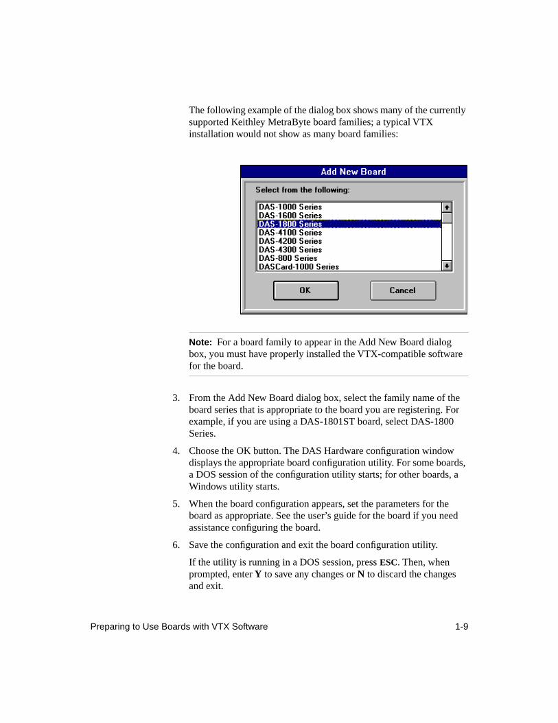
The following example of the dialog box shows many of the currently supported Keithley MetraByte board families; a typical VTX installation would not show as many board families:
Note:
For a board family to appear in the Add New Board dialog box, you must have properly installed the VTX-compatible software
for the board.
3. From the Add New Board dialog box, select the family name of the board series that is appropriate to the board you are registering. For example, if you are using a DAS-1801ST board, select DAS-1800 Series.
4. Choose the OK button. The DAS Hardware configuration window displays the appropriate board configuration utility. For some boards, a DOS session of the configuration utility starts; for other boards, a Windows utility starts.
5. When the board configuration appears, set the parameters for the board as appropriate. See the user’s guide for the board if you need assistance configuring the board.
6. Save the configuration and exit the board configuration utility.
If the utility is running in a DOS session, press
ESC
. Then, when prompted, enter
Y
to save any changes or
N
to discard the changes and exit.
1-10 Installing VTX Software
7. Repeat steps 2 through 6 to register and configure any additional boards.
From the DAS Hardware configuration window, you can access online help by pressing
F1
or by choosing the Help button.
Changing the Configuration of a Registered Board
To change the configuration of a registered board, follow these steps:
1. Select the board from the list in the DAS Hardware configuration window.
2. Choose the Configure button.
3. When the DAS Hardware configuration window displays the appropriate board configuration utility, change the parameters as appropriate to your application.
4. Save your changes and exit to the DAS Hardware configuration window.
Deleting a Registered Board
To delete a board from the list of registered boards, follow these steps:
1. Select the board name from the list in the DAS Hardware configuration window.
2. Choose the Remove button.
3. When prompted, choose the Yes button to confirm the deletion or the No button to cancel the deletion.
Preparing to Use Boards with VTX Software 1-11
Changing an Alias
When you add and configure a board, the VTX software automatically assigns a unique identifier to the board, called an
alias
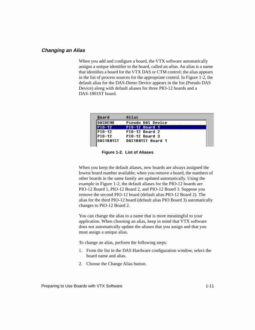
. An alias is a name that identifies a board for the VTX DAS or CTM control; the alias appears in the list of process sources for the appropriate control. In Figure 1-2, the default alias for the DAS-Demo Device appears in the list (Pseudo DAS Device) along with default aliases for three PIO-12 boards and a DAS-1801ST board.
Figure 1-2. List of Aliases
When you keep the default aliases, new boards are always assigned the lowest board number available; when you remove a board, the numbers of other boards in the same family are updated automatically. Using the example in Figure 1-2, the default aliases for the PIO-12 boards are PIO-12 Board 1, PIO-12 Board 2, and PIO-12 Board 3. Suppose you remove the second PIO-12 board (default alias PIO-12 Board 2). The alias for the third PIO-12 board (default alias PIO Board 3) automatically changes to PIO-12 Board 2.
You can change the alias to a name that is more meaningful to your application. When choosing an alias, keep in mind that VTX software does not automatically update the aliases that you assign and that you must assign a unique alias.
To change an alias, perform the following steps:
1. From the list in the DAS Hardware configuration window, select the board name and alias.
2. Choose the Change Alias button.
1-12 Installing VTX Software
3. From the Change Board Alias Name dialog box, enter a new alias for the board.
4. Choose the OK button to save the change and close the dialog box. The new alias appears in the list.
Note:
Once you change an alias, the VTX software no longer handles the alias as a default alias.
Even if you supply a name that is identical to the default alias,
the name you supply is effectively frozen and not updated if another board in the same family is removed from the list.
In general, do not change the alias of a board that you have already
included in a VTX application.
Specifying Engineering Units
The VTX DAS control can convert analog input data into engineering units that are useful to your application. For example, if you connect thermocouples to your analog input channels, you can use the DAS control to acquire data from the thermocouples and then convert the raw analog input data to the temperature units you require. To enable the DAS control to perform the conversion, you must perform the following tasks:
1. Specify the sensors or equations to use for the conversion in the Engineering Units window of the VTX Configuration utility.
2. Set the properties for the analog input operation. See the topics, "Setting Up DAS Processes" and "Setting Up Analog In Processes," in the online help for detailed instructions.
In particular, ensure that you set the DataConvType property of the DAS control to Eng Units.
Note:
The Eng Units setting for the DataConvType property automatically sets the DataType property to Single. If your application requires a different data type, set the DataType property
accordingly.
Preparing to Use Boards with VTX Software 1-13
To specify the type of sensor or equation to use in converting acquired data automatically during an analog input operation, perform these steps:
1. From the Keithley VTX group window in the Windows 3.x Program Manager, click the VTX Configuration icon.
From the Windows 95 task bar, click Start, then slide the cursor over Programs, then Keithley VTX, and click VTX Configuration.
2. From the list in the DAS Hardware configuration window, select the board name and alias.
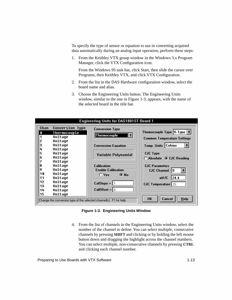
3. Choose the Engineering Units button. The Engineering Units window, similar to the one in Figure 1-3, appears, with the name of the selected board in the title bar.
Figure 1-3. Engineering Units Window
4. From the list of channels in the Engineering Units window, select the number of the channel to define. You can select multiple, consecutive channels by pressing
SHIFT
and clicking or by holding the left mouse button down and dragging the highlight across the channel numbers. You can select multiple, non-consecutive channels by pressing
CTRL
and clicking each channel number.
1-14 Installing VTX Software
By default, the conversion type is voltage and calibration is disabled.
5. From the pull-down list in the Conversion Type option, select a conversion type. In Figure 1-3, the Thermocouple conversion type is selected for channel 0.
6. Depending on the conversion type you select, you may need to set additional parameters. In Figure 1-3, the additional parameters include the thermocouple type, temperature units, CJC type, and CJC parameters.
7. If you want to apply calibration, click the radio button next to Yes and then set the calibration slope and offset.
When you enable calibration here, the DAS control converts raw data to voltages, applies the calibration, and then converts the calibrated voltages to engineering units. You can send the converted data to the Conversion process of the Computation control if you want to apply another calibration after the initial conversion.
For example, suppose raw data is converted to 4.50 V. After calibration, the DAS control converts the calibrated data of 4.51 V to 36.20
°
C. If you then use the Computation control to calibrate the temperature, the calibrated temperature might change to 36.24
°
C.
Note:
The default settings for the calibration slope and offset disable calibration. To enable calibration, you must change the calibration
slope and offset.
8. Repeat steps 4 through 7 for each channel whose data you want to convert.
9. To save your changes and return to the main DAS Hardware configuration window, choose the OK button. To cancel your changes and exit to the main window, choose the Cancel button.
The Engineering Units window provides a Help button that you can use to display additional information.
Preparing to Use Boards with VTX Software 1-15
Reserving Memory
When you install VTX software, the Keithley Memory Manager (KMM) is automatically installed so that your VTX applications can use the KMM instead of the appropriate Windows memory manager. If you installed VTX software on a Windows 3.x system, the KMM reserved 128K bytes of memory for VTX data acquisition applications at installation. If you installed VTX software on a Windows 95 system, you need to use the KMM tab of the VTX Configuration utility to specify the amount of memory and then restart Windows 95 to activate the KMM.
For Windows 3.x systems the VTX installation program copies a file called VDMAD.386, which is a customized version of Microsoft's Virtual DMA Driver (VDMAD). VDMAD.386 contains a copy of Microsoft's Virtual DMA Driver and a group of functions added to perform the KMM functions. The VTX installation program replaces Microsoft's Virtual DMA Driver with the VDMAD.386 file and modifies your SYSTEM.INI file accordingly.
For Windows 95 systems the VTX installation program copies a file called VDMAD.VXD, which is a customized version of Microsoft's Virtual DMA Driver (VDMAD). VDMAD.VXD contains a copy of Microsoft's Virtual DMA Driver and a group of functions added to perform the KMM functions. When you run the KMM tab of the VTX Configuration utility and then restart Windows 95, the VTX software replaces Microsoft's Virtual DMA Driver with the VDMAD.VXD file and modifies the Windows 95 Registry and your SYSTEM.INI file accordingly.
For any Windows system, you can change the amount of memory reserved for your VTX applications using the following steps:
1. From the Keithley VTX group window in the Windows 3.x Program Manager, double-click the VTX Configuration icon.
From the Windows 95 task bar, click the Start button, then move the cursor over Programs, followed by Keithley VTX, and then click VTX Configuration once.
2. When the DAS Hardware configuration window appears, click the Keithley Memory Manager tab to display the KMM component of the VTX Configuration utility.
1-16 Installing VTX Software
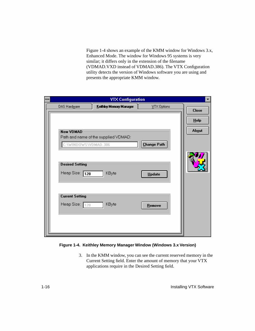
Figure 1-4 shows an example of the KMM window for Windows 3.x, Enhanced Mode. The window for Windows 95 systems is very similar; it differs only in the extension of the filename (VDMAD.VXD instead of VDMAD.386). The VTX Configuration utility detects the version of Windows software you are using and presents the appropriate KMM window.
Figure 1-4. Keithley Memory Manager Window (Windows 3.x Version)
3. In the KMM window, you can see the current reserved memory in the Current Setting field. Enter the amount of memory that your VTX applications require in the Desired Setting field.
Preparing to Use Boards with VTX Software 1-17
The amount of memory you can reserve depends on the total available memory and on the memory requirements of Windows and other Windows applications. See the online help for the KMM and the user’s guide for your board for details on reserving memory.
4. Choose the Update button.
5. When prompted, you can put the changes into effect immediately by clicking the Restart Windows button. Note that, for Windows 3.x, the KMM component of the VTX Configuration utility updates the SYSTEM.INI file automatically. Similarly, for Windows 95, the KMM component updates the Registry and the SYSTEM.INI file automatically. In addition, for all supported Windows versions, the KMM component shuts down Windows, then brings it back up.
To return to the VTX Configuration utility without implementing the changes immediately, choose the Return to Utility button. The changes will take effect the next time you start Windows.
After you register and configure your board and allocate memory for your applications, the next step depends on whether your board is already installed:
●
If your board is already installed and you chose to load the VTX controls automatically into your Visual Basic Toolbox, you can start using the VTX controls. If you chose not to load the VTX controls at installation, see “Loading VTX Controls,” on page 1-18 for instructions.
●
If your board is not already installed, continue to the next section.
Installing Hardware
After you register and configure a Keithley MetraByte board for use with VTX software, perform the following tasks to install your board:
1. Power down the computer.
2. Set the appropriate hardware switches on the board.
3. Install the board in the computer.
4. Power up the computer.
For assistance with these tasks, see the user’s guide for the board.
1-18 Installing VTX Software
Once you have completed these tasks, you can start using the VTX controls as long as you loaded them automatically at installation. If you chose not to load them automatically, load the VTX controls into your Visual Basic Toolbox; the next section explains how.
Loading VTX Controls
VTX custom controls are extensions to your Visual Basic Toolbox. Use the VTX controls in the same way you use the standard Visual Basic Toolbox controls. The VTX custom controls are 16-bit controls and are compatible with Visual Basic 3.0 and the 16-bit versions of Visual Basic 4.0, Professional and Enterprise Editions.
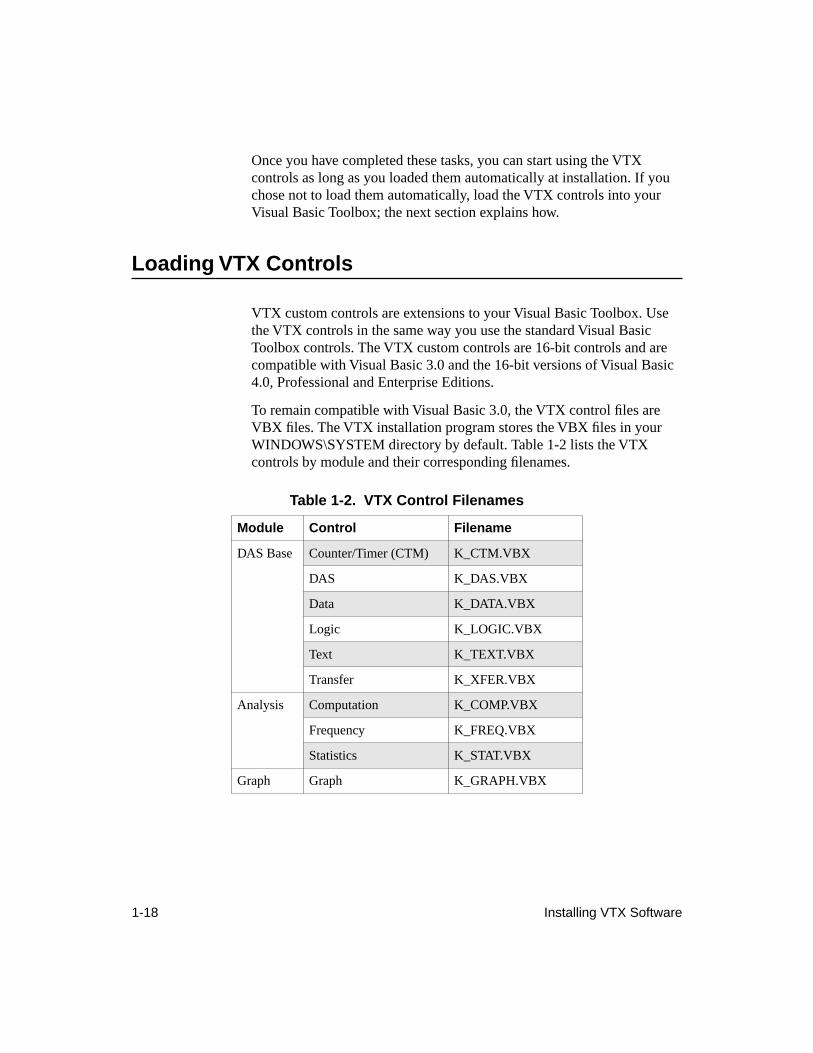
To remain compatible with Visual Basic 3.0, the VTX control files are VBX files. The VTX installation program stores the VBX files in your WINDOWS\SYSTEM directory by default. Table 1-2 lists the VTX controls by module and their corresponding filenames.
Table 1-2. VTX Control Filenames
Module Control Filename
DAS Base Counter/Timer (CTM) K_CTM.VBX
DAS K_DAS.VBX
Data K_DATA.VBX
Logic K_LOGIC.VBX
Text K_TEXT.VBX
Transfer K_XFER.VBX
Analysis Computation K_COMP.VBX
Frequency K_FREQ.VBX
Statistics K_STAT.VBX
Graph Graph K_GRAPH.VBX
Loading VTX Controls 1-19
If you chose not to load the VTX custom controls automatically into your Visual Basic Toolbox at installation, you can load them now in either of two ways:
●
Manually — Add the control files as needed for each project. Use the manual option if you use Visual Basic for several different types of applications.
●
Automatically — Add the control files to the AUTOLOAD.MAK project (Visual Basic 3.0) or the AUTO16LD.VBP project (Visual Basic 4.0) so that the controls are loaded into the Toolbox every time you start Visual Basic. Use the automatic option if you use Visual Basic exclusively for data acquisition applications. If you selected the option to load the VTX custom controls at installation, the installation program added them to the AUTOLOAD.MAK or AUTO16LD.VBP project for you.
Adding a Control to an Application Manually
Before you can use a VTX custom control in an application, you need to add the control’s VBX file to your project. The steps for adding custom controls to an application differ between Visual Basic 3.0 and Visual Basic 4.0. Follow the instructions in the section appropriate to your version of Visual Basic.
The main difference between loading the controls into the Visual Basic Toolbox on Windows 3.x and Windows 95 is the way in which you start Visual Basic:
●
From the Windows 3.x Program Manager, double-click the Visual Basic icon in the appropriate program group.
●
From the Windows 95 task bar, click Start, then slide the cursor over Programs, followed by Visual Basic, and then click the appropriate Visual Basic icon in the Visual Basic menu.
Visual Basic 3.0
To add the VTX controls to your Visual Basic 3.0 Toolbox, perform the following steps:
1. With Visual Basic 3.0 running, open your project file (
projectname
.MAK). If you are starting a new project, select New Project from the File menu.
2. From the Visual Basic File menu, select Add File.
3. From the Add File dialog box, locate the WINDOWS\SYSTEM directory.
4. From the list of files in the WINDOWS\SYSTEM directory, select the filename for the VTX control (
control
.VBX) that you want to load. For example, K_DATA.VBX is the filename of the VTX Data control. See Table 1-2 on page 1-18 for the complete list of VTX control filenames.
5. Choose the OK button. The name of the control file appears in the Project window. In addition, the control icon appears in the Toolbox.
6. Repeat steps 2 through 4 for each VTX control that you want to use in your application.
7. From the File menu, select Save Project.
Visual Basic 4.0
To add the VTX controls to your Visual Basic 4.0 Toolbox, perform the following steps:
1. With Visual Basic 4.0 running, open your project file (
projectname
.VBP). If you are starting a new project, select New Project from the File menu.
2. From the Tools menu, select Custom Controls or press
CTRL+T
. When the Custom Controls dialog box appears, you can make viewing easier by using the Show option to specify that only selected items are displayed in the Available Controls list box.
3. Choose the Browse button to display the Add Custom Controls dialog box.
4. From the Add Custom Controls dialog box, locate the WINDOWS\SYSTEM directory.
Loading VTX Controls 1-21
5. From the list of files in the WINDOWS\SYSTEM directory, select the filename for the VTX control (
control
.VBX) that you want to load. For example, K_DATA.VBX is the filename of the VTX Data control. See Table 1-2 on page 1-18 for the complete list of VTX control filenames.
After you select the filename, the Custom Controls dialog box appears with the selected control listed and checked in the Available Controls list box.
6. Repeat steps 3 through 5 for each additional VTX control that you want to use in your application.
7. When ready, choose the OK button in the Custom Controls dialog box. The name of each selected control file appears in the Project window. In addition, the control icon appears in the Toolbox.
8. From the File menu, select Save Project.
Loading VTX Controls Automatically
If you want the VTX custom controls to be available in the Toolbox each time you start Visual Basic and you did not select the option to load the controls at installation, you can load the controls into the AUTOLOAD.MAK (Visual Basic 3.0) or AUTO16LD.VBP (Visual Basic 4.0) project now. The steps for adding custom controls differ between Visual Basic 3.0 and Visual Basic 4.0. Follow the instructions in the section appropriate to your version of Visual Basic.
The main difference between loading the controls into the Visual Basic Toolbox on Windows 3.x and Windows 95 is the way in which you start Visual Basic:
● From the Windows 3.x Program Manager, double-click the Visual Basic icon in the Visual Basic program group.
● From the Windows 95 task bar, click Start, then slide the cursor over Programs, followed by Visual Basic, and then click the appropriate Visual Basic icon in the Visual Basic menu.
1-22 Installing VTX Software
Visual Basic 3.0
To add the VTX controls to your AUTOLOAD.MAK project so that the controls load automatically each time you run Visual Basic, perform the following steps:
1. From the Visual Basic File menu, select Open Project.
2. From the Open Project dialog box, select AUTOLOAD.MAK from your Visual Basic root directory (for example, C:\VB).
3. Choose the OK button.
The project window for AUTOLOAD.MAK appears. This window lists the files that are automatically added to each new application. In addition, the list contains the names of the VBX files for the controls that automatically appear in the Toolbox each time you start Visual Basic.
4. From the File menu, select Add File.
5. From the Add File dialog box, locate the WINDOWS\SYSTEM directory.
6. From the list of files in the WINDOWS\SYSTEM directory, select the filename for the VTX control (control.VBX) that you want to load automatically. For example, K_DATA.VBX is the filename of the VTX Data control. See Table 1-2 on page 1-18 for the complete list of VTX control filenames.
7. Choose the OK button. The name of the control file appears in the AUTOLOAD.MAK project window.
8. Repeat steps 4 through 7 for each VTX control that you want to load automatically.
9. From the File menu, select Save Project to save the modified AUTOLOAD.MAK file.
Each time you start Visual Basic, the VTX controls appear in the Toolbox automatically.
Loading VTX Controls 1-23
Visual Basic 4.0
To add the VTX controls to your AUTO16LD.VBP project so that the controls load automatically each time you run Visual Basic, perform the following steps:
1. With Visual Basic 4.0 running, select Open Project from the File menu.
2. From the Open Project dialog box, select AUTO16LD.VBP from your Visual Basic root directory (for example, C:\VB).
3. Choose the OK button.
4. From the Tools menu, select Custom Controls or press CTRL+T . When the Custom Controls dialog box appears, you can make viewing easier by using the Show option to specify that only selected items are displayed in the Available Controls list box.
5. Choose the Browse button to display the Add Custom Controls dialog box.
6. From the Add Custom Controls dialog box, locate the WINDOWS\SYSTEM directory.
7. From the list of files in the WINDOWS\SYSTEM directory, select the filename for the VTX control (control.VBX) that you want to load. For example, K_DATA.VBX is the filename of the VTX Data control. See Table 1-2 on page 1-18 for the complete list of VTX control filenames.
After you select the filename, the Custom Controls dialog box appears with the selected control listed and checked in the Available Controls list box.
8. Repeat steps 5 through 7 for each additional VTX control that you want to load automatically.
9. When ready, choose the OK button in the Custom Controls dialog box. The name of each selected control file appears in the Project window. In addition, the control icon appears in the Toolbox.
10. From the File menu, select Save Project to save the modified AUTO16LD.VBP file.
1-24 Installing VTX Software
Creating Your First VTX Application
After installing the VTX software and loading the controls into Visual Basic, follow the tutorial presented in Chapter 2 to create your first VTX application.
Assumptions 2-1
2
Creating Your First VTXApplication
In this chapter, you will build a simple application that reads and displays a single data point by
1. Designing the user interface
2. Setting the properties
3. Connecting the VTX controls
4. Writing code
5. Running the program
Assumptions
This tutorial assumes
●
You have loaded the VTX controls into your Visual Basic Toolbox. If you did not load the VTX controls at installation, see “Loading VTX Controls” on page 1-18 for instructions.
●
You are familiar with the Windows environment and know how to use a mouse.
●
You are familiar with the basic elements of the Visual Basic interface. If this is your first exposure to Visual Basic, take the time to read through the first three chapters of the
Visual Basic
Programmer’s Guide
before you begin.
2-2 Creating Your First VTX Application
Overview of the Application
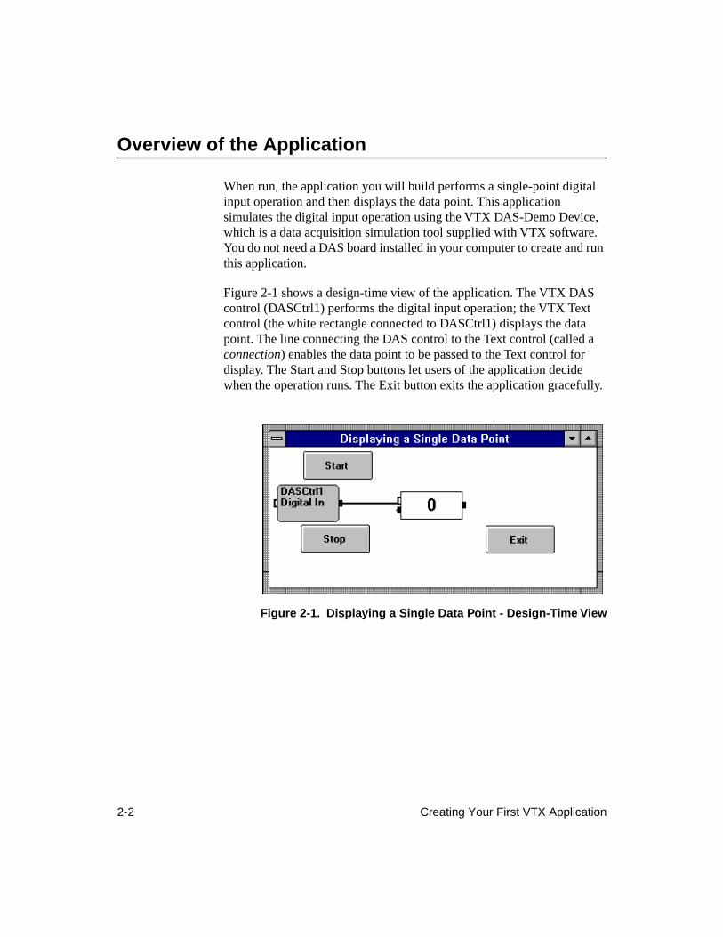
When run, the application you will build performs a single-point digital input operation and then displays the data point. This application simulates the digital input operation using the VTX DAS-Demo Device, which is a data acquisition simulation tool supplied with VTX software. You do not need a DAS board installed in your computer to create and run this application.
Figure 2-1 shows a design-time view of the application. The VTX DAS control (DASCtrl1) performs the digital input operation; the VTX Text control (the white rectangle connected to DASCtrl1) displays the data point. The line connecting the DAS control to the Text control (called a
connection
) enables the data point to be passed to the Text control for display. The Start and Stop buttons let users of the application decide when the operation runs. The Exit button exits the application gracefully.
Figure 2-1. Displaying a Single Data Point - Design-Time View
Design the User Interface 2-3
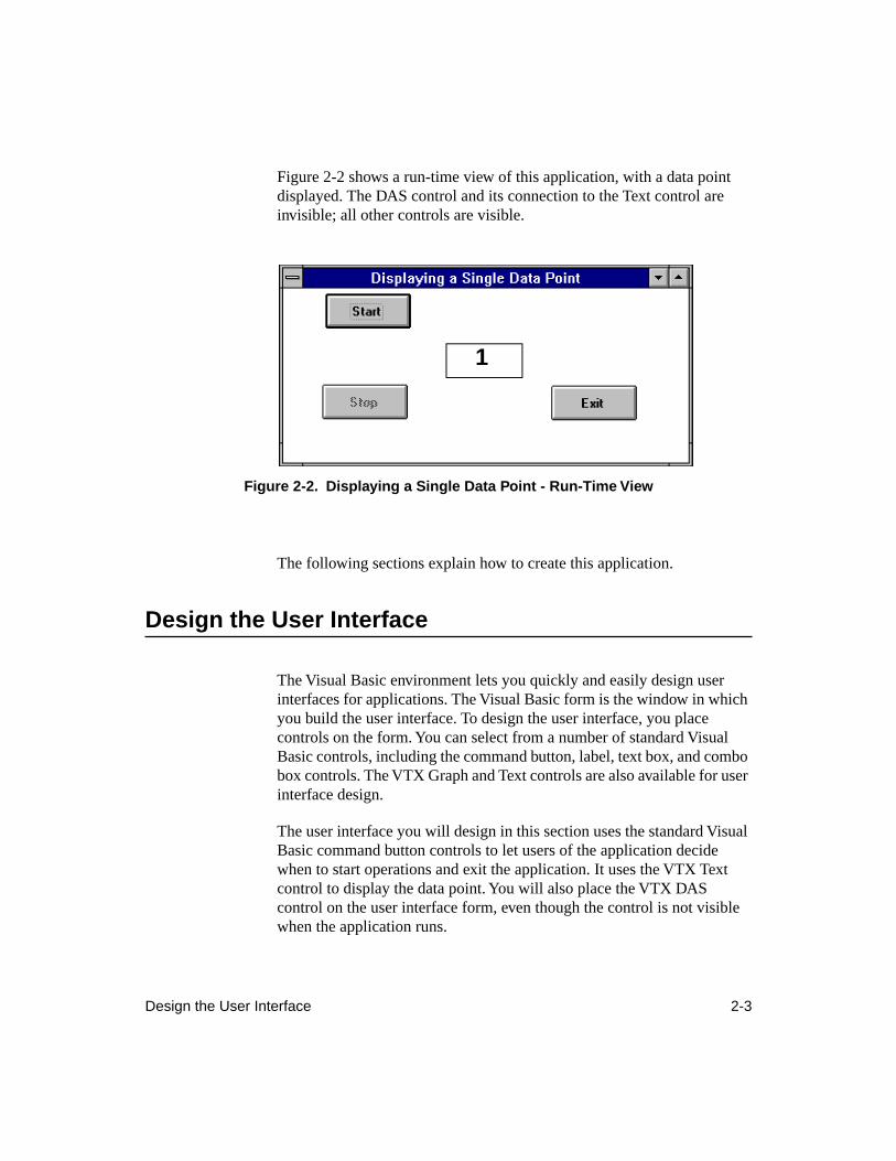
Figure 2-2 shows a run-time view of this application, with a data point displayed. The DAS control and its connection to the Text control are invisible; all other controls are visible.
Figure 2-2. Displaying a Single Data Point - Run-Time View
The following sections explain how to create this application.
Design the User Interface
The Visual Basic environment lets you quickly and easily design user interfaces for applications. The Visual Basic form is the window in which you build the user interface. To design the user interface, you place controls on the form. You can select from a number of standard Visual Basic controls, including the command button, label, text box, and combo box controls. The VTX Graph and Text controls are also available for user interface design.
The user interface you will design in this section uses the standard Visual Basic command button controls to let users of the application decide when to start operations and exit the application. It uses the VTX Text control to display the data point. You will also place the VTX DAS control on the user interface form, even though the control is not visible when the application runs.
1
2-4 Creating Your First VTX Application
To design the user interface, follow these steps:
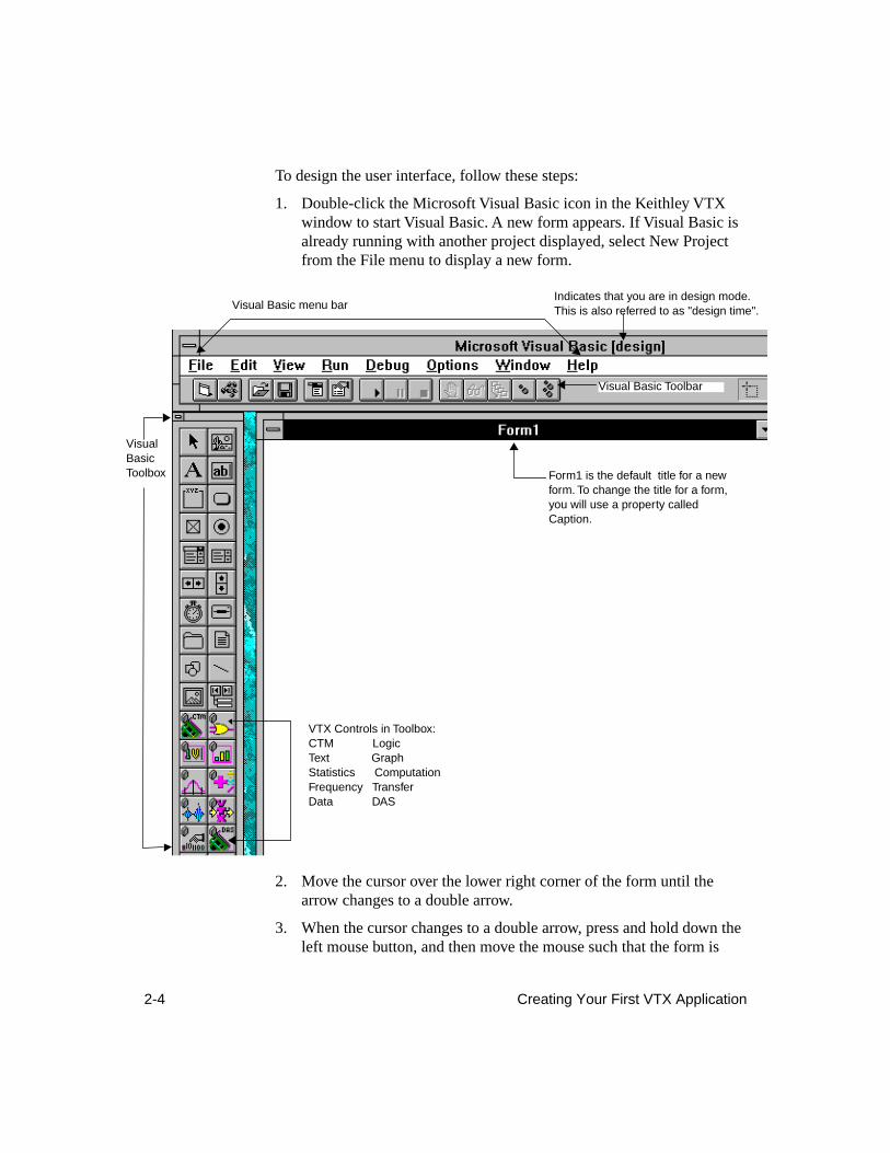
1. Double-click the Microsoft Visual Basic icon in the Keithley VTX window to start Visual Basic. A new form appears. If Visual Basic is already running with another project displayed, select New Project from the File menu to display a new form.
2. Move the cursor over the lower right corner of the form until the arrow changes to a double arrow.
3. When the cursor changes to a double arrow, press and hold down the left mouse button, and then move the mouse such that the form is
Form1 is the default title for a new form. To change the title for a form, you will use a property called Caption.
Visual Basic menu bar
VTX Controls in Toolbox:CTM LogicText GraphStatistics ComputationFrequency TransferData DAS
Indicates that you are in design mode. This is also referred to as "design time".
Visual Basic Toolbar
Visual Basic Toolbox
Design the User Interface 2-5
approximately four inches wide and two inches high. When you set the properties later, you will specify the form size with more exact dimensions.
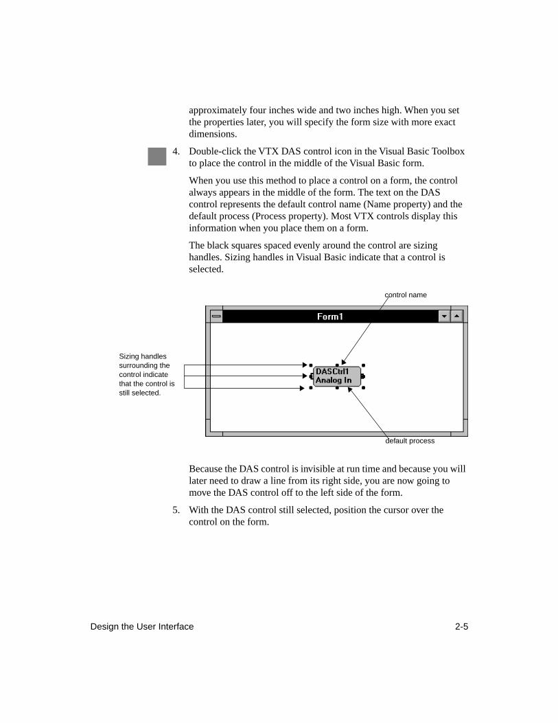
4. Double-click the VTX DAS control icon in the Visual Basic Toolbox to place the control in the middle of the Visual Basic form.
When you use this method to place a control on a form, the control always appears in the middle of the form. The text on the DAS control represents the default control name (Name property) and the default process (Process property). Most VTX controls display this information when you place them on a form.
The black squares spaced evenly around the control are sizing handles. Sizing handles in Visual Basic indicate that a control is selected.
Because the DAS control is invisible at run time and because you will later need to draw a line from its right side, you are now going to move the DAS control off to the left side of the form.
5. With the DAS control still selected, position the cursor over the control on the form.
Sizing handles surrounding the control indicate that the control is still selected.
control name
default process
2-6 Creating Your First VTX Application
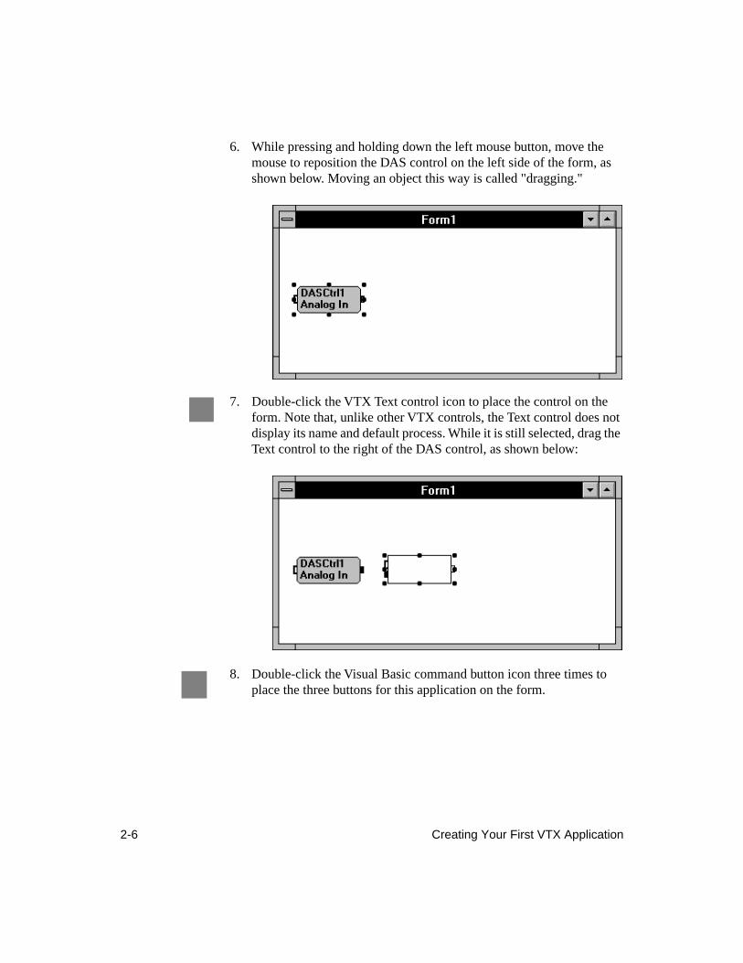
6. While pressing and holding down the left mouse button, move the mouse to reposition the DAS control on the left side of the form, as shown below. Moving an object this way is called "dragging."
7. Double-click the VTX Text control icon to place the control on the form. Note that, unlike other VTX controls, the Text control does not display its name and default process. While it is still selected, drag the Text control to the right of the DAS control, as shown below:
8. Double-click the Visual Basic command button icon three times to place the three buttons for this application on the form.
Design the User Interface 2-7
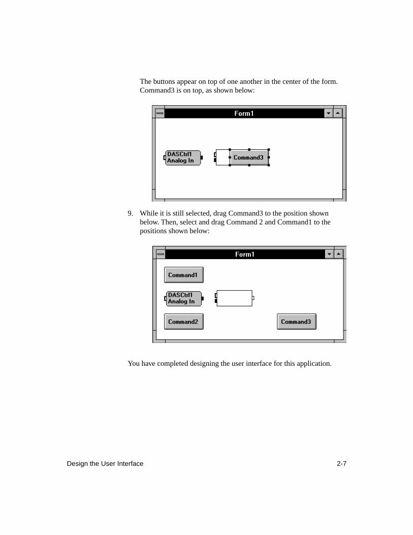
The buttons appear on top of one another in the center of the form. Command3 is on top, as shown below:
9. While it is still selected, drag Command3 to the position shown below. Then, select and drag Command 2 and Command1 to the positions shown below:
You have completed designing the user interface for this application.
2-8 Creating Your First VTX Application
Before continuing, save your work by following these steps:
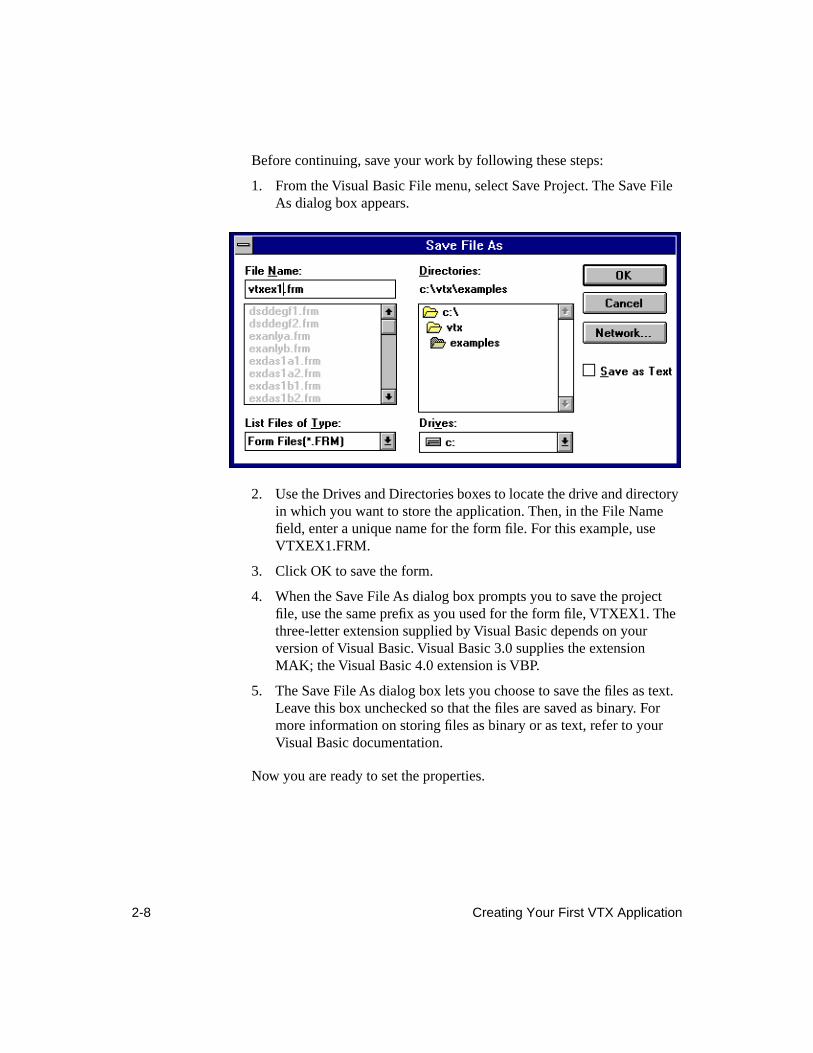
1. From the Visual Basic File menu, select Save Project. The Save File As dialog box appears.
2. Use the Drives and Directories boxes to locate the drive and directory in which you want to store the application. Then, in the File Name field, enter a unique name for the form file. For this example, use VTXEX1.FRM.
3. Click OK to save the form.
4. When the Save File As dialog box prompts you to save the project file, use the same prefix as you used for the form file, VTXEX1. The three-letter extension supplied by Visual Basic depends on your version of Visual Basic. Visual Basic 3.0 supplies the extension MAK; the Visual Basic 4.0 extension is VBP.
5. The Save File As dialog box lets you choose to save the files as text. Leave this box unchecked so that the files are saved as binary. For more information on storing files as binary or as text, refer to your Visual Basic documentation.
Now you are ready to set the properties.
Set the Properties 2-9
Set the Properties
In Visual Basic, properties can represent physical attributes of an object. For example, the Caption property lets you specify the title for a form or command button. Similarly, the BackColor property lets you specify the background color for a form or for the VTX Text control. For VTX controls, properties also represent parameters for the process that you want the control to perform. For example, the Samples property of the VTX DAS control lets you specify the number of data points to read from each channel during an analog input or digital input operation.
After designing the user interface, your next task is to set the properties for the form and the controls.
Set the Form Properties
You can use many different properties to set up forms in Visual Basic. For purposes of this tutorial, you will specify the form title (Caption), dimensions (Height and Width), background color (BackColor), and the name you will use to reference the form in code (Name).
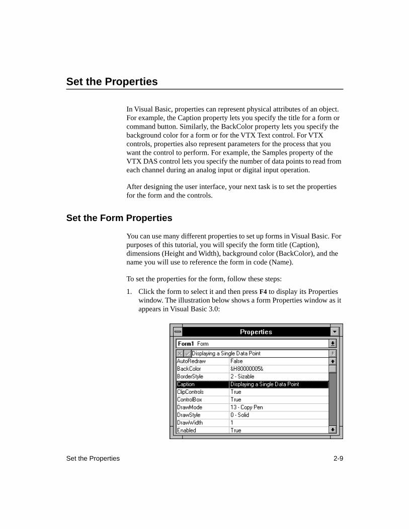
To set the properties for the form, follow these steps:
1. Click the form to select it and then press
F4
to display its Properties window. The illustration below shows a form Properties window as it appears in Visual Basic 3.0:
2-10 Creating Your First VTX Application
2. From the Properties window, double-click the Caption property. When the default text is highlighted, enter the following text:
Displaying a Single Data Point
3. Locate and double-click the Height property. In Visual Basic, the default dimensions for a form are expressed in a special unit called
twips
; there are 1440 twips in an inch.
4. When the default Height setting is highlighted, enter the following dimension:
3000
This changes the height of the form.
5. Locate and double-click the Width property.
6. When the default setting is highlighted, enter the following dimension (twips):
6000
This changes the width of the form.
7. Locate and double-click the BackColor property.
8. When the color dialog box appears, click any color you want to use. The hexadecimal code for the color appears as the current setting and the background color of the form changes to reflect your choice.
9. Finally, locate and double-click the Name property. When the default text is highlighted, enter the following text:
frmMain
In Visual Basic, every object has a Name property. You use the text entered for the Name property to reference an object in code.
Each VTX control has a default Name that includes the control name (or an abbreviation for the name), the abbreviation "Ctrl", and a number that represents the instance of the control on the form. For example, DASCtrl1 is the first DAS control placed on a form.
10. From the File menu, select Save Project. Because you have already specified filenames, no dialog box appears; Visual Basic saves the changes.
Now that you have set the form properties, you can begin setting up the digital input operation and the display of the data point by setting properties for the VTX controls.
Set the Properties 2-11
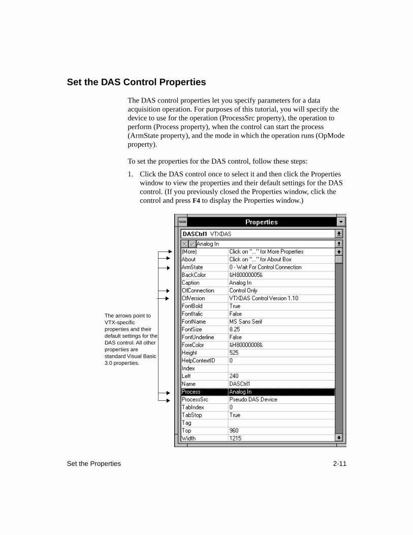
Set the DAS Control Properties
The DAS control properties let you specify parameters for a data acquisition operation. For purposes of this tutorial, you will specify the device to use for the operation (ProcessSrc property), the operation to perform (Process property), when the control can start the process (ArmState property), and the mode in which the operation runs (OpMode property).
To set the properties for the DAS control, follow these steps:
1. Click the DAS control once to select it and then click the Properties window to view the properties and their default settings for the DAS control. (If you previously closed the Properties window, click the control and press
F4
to display the Properties window.)
The arrows point to VTX-specific properties and their default settings for the DAS control. All other properties are standard Visual Basic 3.0 properties.
2-12 Creating Your First VTX Application
2. From the Properties window, check the setting of the ProcessSrc property to ensure that it is Pseudo DAS Device, which is the alias for the DAS-Demo Device.
If the setting is not Pseudo DAS Device, double-click the ProcessSrc property until the Pseudo DAS Device setting appears.
Alternatively, click the down arrow next to the highlighted setting to display the list of available process sources, and then click the Pseudo DAS Device setting. If you have already registered and configured boards, the aliases you assigned to the boards appear in this list.
3. From the Properties window, double-click the Process property twice to change its value from Analog In to Digital In (digital input operation). Alternatively, double-click the property once and then click the down arrow next to the highlighted setting to display the list of available processes.
4. From the Properties window, double-click the ArmState property until the setting changes to 2 - Hold. This setting prevents the DAS control from starting until the Start command button is clicked.
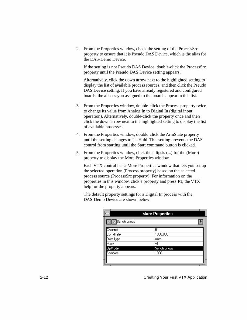
5. From the Properties window, click the ellipsis (...) for the (More) property to display the More Properties window.
Each VTX control has a More Properties window that lets you set up the selected operation (Process property) based on the selected process source (ProcessSrc property). For information on the properties in this window, click a property and press
F1
; the VTX help for the property appears.
The default property settings for a Digital In process with the DAS-Demo Device are shown below:
Set the Properties 2-13
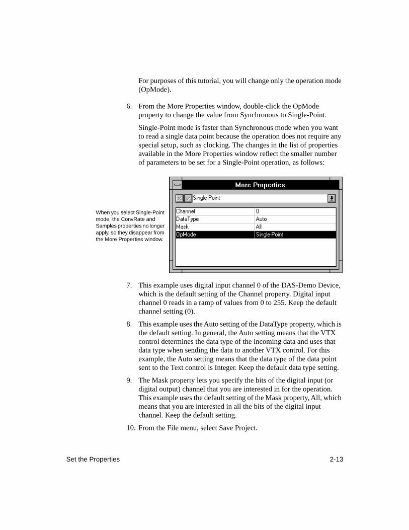
For purposes of this tutorial, you will change only the operation mode (OpMode).
6. From the More Properties window, double-click the OpMode property to change the value from Synchronous to Single-Point.
Single-Point mode is faster than Synchronous mode when you want to read a single data point because the operation does not require any special setup, such as clocking. The changes in the list of properties available in the More Properties window reflect the smaller number of parameters to be set for a Single-Point operation, as follows:
7. This example uses digital input channel 0 of the DAS-Demo Device, which is the default setting of the Channel property. Digital input channel 0 reads in a ramp of values from 0 to 255. Keep the default channel setting (0).
8. This example uses the Auto setting of the DataType property, which is the default setting. In general, the Auto setting means that the VTX control determines the data type of the incoming data and uses that data type when sending the data to another VTX control. For this example, the Auto setting means that the data type of the data point sent to the Text control is Integer. Keep the default data type setting.
9. The Mask property lets you specify the bits of the digital input (or digital output) channel that you are interested in for the operation. This example uses the default setting of the Mask property, All, which means that you are interested in all the bits of the digital input channel. Keep the default setting.
10. From the File menu, select Save Project.
When you select Single-Point mode, the ConvRate and Samples properties no longer apply, so they disappear from the More Properties window.
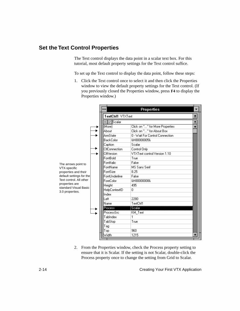
2-14 Creating Your First VTX Application
Set the Text Control Properties
The Text control displays the data point in a scalar text box. For this tutorial, most default property settings for the Text control suffice.
To set up the Text control to display the data point, follow these steps:
1. Click the Text control once to select it and then click the Properties window to view the default property settings for the Text control. (If you previously closed the Properties window, press
F4
to display the Properties window.)
2. From the Properties window, check the Process property setting to ensure that it is Scalar. If the setting is not Scalar, double-click the Process property once to change the setting from Grid to Scalar.
The arrows point to VTX-specific properties and their default settings for the Text control. All other properties are standard Visual Basic 3.0 properties.

Set the Properties 2-15
3. Similarly, check the ProcessSrc property setting to ensure that it is KM_Text. If the setting is not KM_Text, double-click the property until KM_Text appears.
4. The Text control must wait until it receives the data point from the DAS control before it can run the Scalar process. Therefore, keep the default setting of the ArmState property, 0 - Wait For Control Connection, for the Text control.
5. From the Properties window, click the ellipsis (...) for the (More) property to display the More Properties window. For information on these properties, click the property and press
F1
. The VTX help for the property appears.
6. For this example, the data point will be centered in the display. However, the property that specifies the horizontal alignment of text (HAlignment) is ignored unless the MultiLine property setting is True. Double-click the MultiLine property to change its setting from False to True.
7. To center the data point value in the Text control display, double-click the HAlignment property twice, which changes the setting from 0 - Left to 2 - Center.
8. From the File menu, select Save Project.
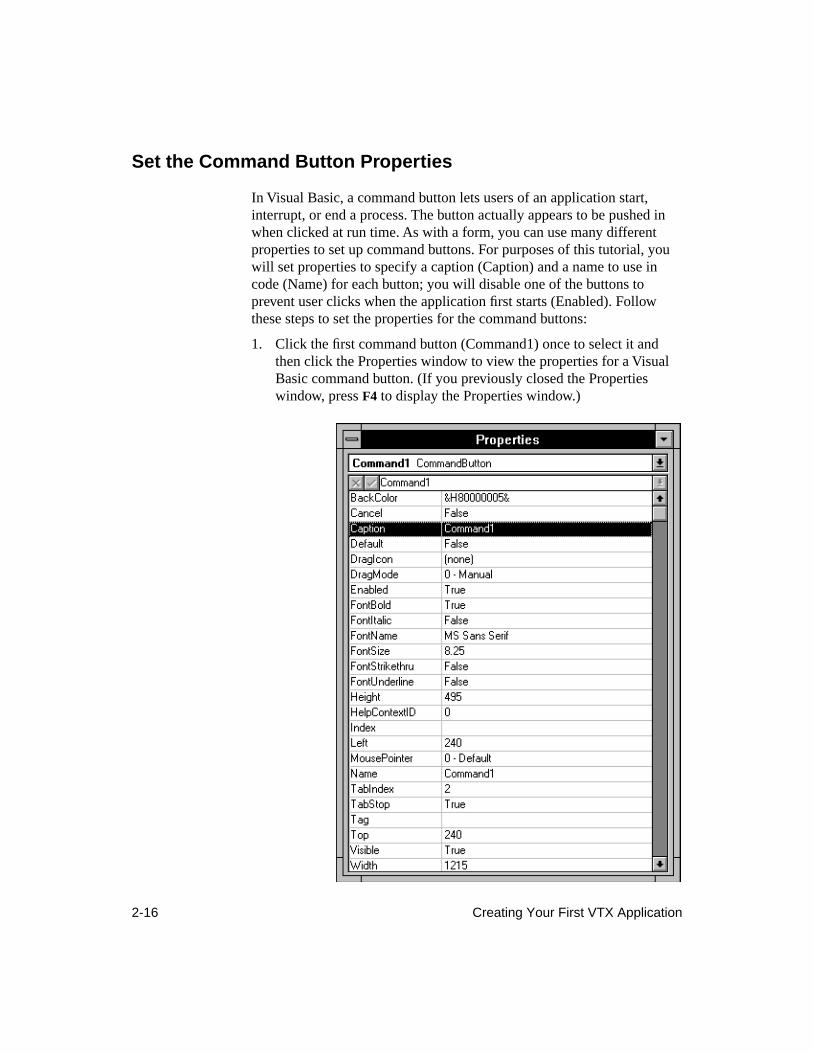
2-16 Creating Your First VTX Application
Set the Command Button Properties
In Visual Basic, a command button lets users of an application start, interrupt, or end a process. The button actually appears to be pushed in when clicked at run time. As with a form, you can use many different properties to set up command buttons. For purposes of this tutorial, you will set properties to specify a caption (Caption) and a name to use in code (Name) for each button; you will disable one of the buttons to prevent user clicks when the application first starts (Enabled). Follow these steps to set the properties for the command buttons:
1. Click the first command button (Command1) once to select it and then click the Properties window to view the properties for a Visual Basic command button. (If you previously closed the Properties window, press
F4
to display the Properties window.)
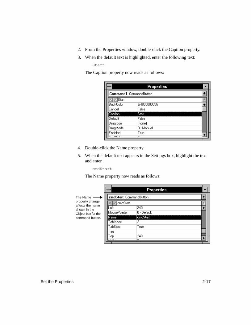
Set the Properties 2-17
2. From the Properties window, double-click the Caption property.
3. When the default text is highlighted, enter the following text:
Start
The Caption property now reads as follows:
4. Double-click the Name property.
5. When the default text appears in the Settings box, highlight the text and enter
cmdStart
The Name property now reads as follows:
The Name property change affects the name shown in the Object box for the command button.
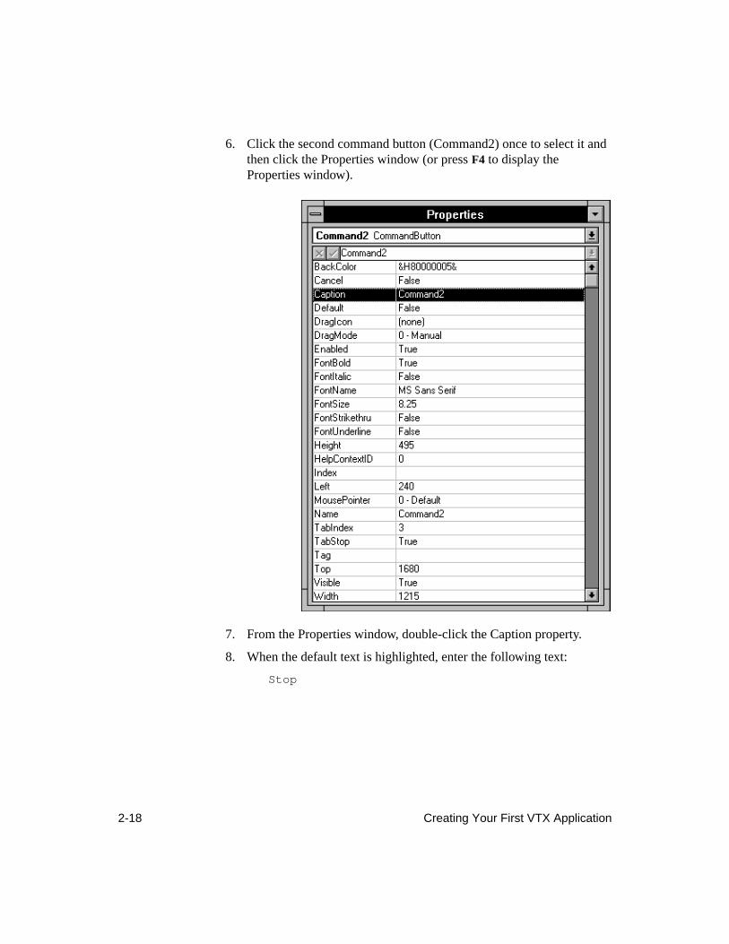
2-18 Creating Your First VTX Application
6. Click the second command button (Command2) once to select it and then click the Properties window (or press
F4
to display the Properties window).
7. From the Properties window, double-click the Caption property.
8. When the default text is highlighted, enter the following text:
Stop
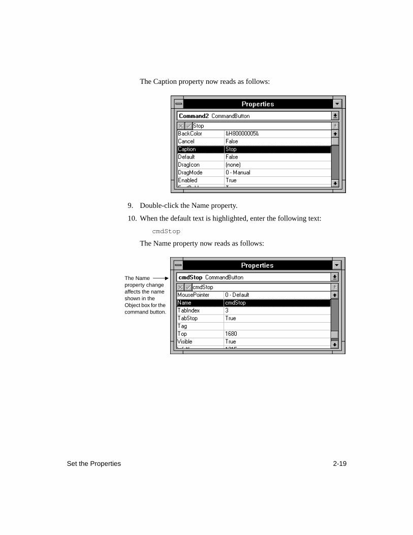
Set the Properties 2-19
The Caption property now reads as follows:
9. Double-click the Name property.
10. When the default text is highlighted, enter the following text:
cmdStop
The Name property now reads as follows:
The Name property change affects the name shown in the Object box for the command button.
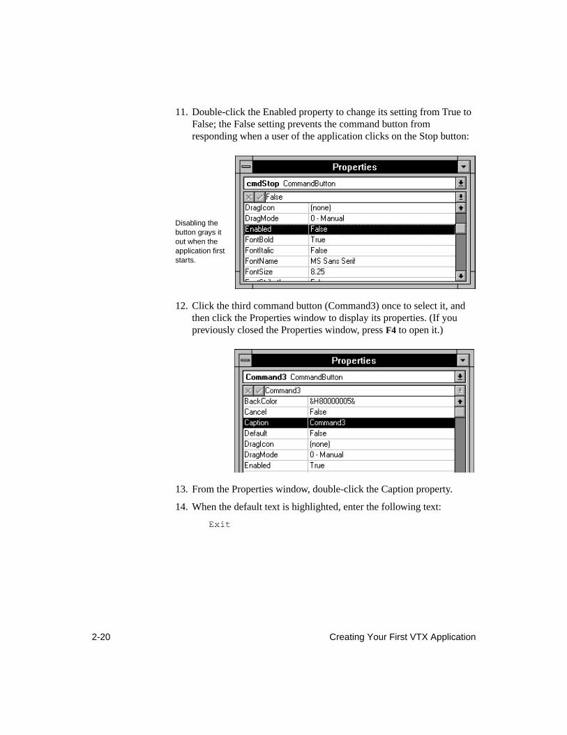
2-20 Creating Your First VTX Application
11. Double-click the Enabled property to change its setting from True to False; the False setting prevents the command button from responding when a user of the application clicks on the Stop button:
12. Click the third command button (Command3) once to select it, and then click the Properties window to display its properties. (If you previously closed the Properties window, press
F4
to open it.)
13. From the Properties window, double-click the Caption property.
14. When the default text is highlighted, enter the following text:
Exit
Disabling the button grays it out when the application first starts.
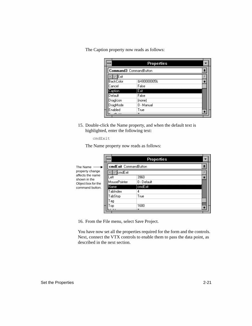
Set the Properties 2-21
The Caption property now reads as follows:
15. Double-click the Name property, and when the default text is highlighted, enter the following text:
cmdExit
The Name property now reads as follows:
16. From the File menu, select Save Project.
You have now set all the properties required for the form and the controls. Next, connect the VTX controls to enable them to pass the data point, as described in the next section.
The Name property change affects the name shown in the Object box for the command button.
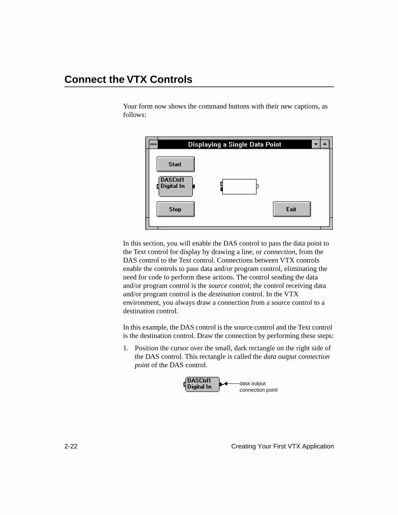
2-22 Creating Your First VTX Application
Connect the VTX Controls
Your form now shows the command buttons with their new captions, as follows:
In this section, you will enable the DAS control to pass the data point to the Text control for display by drawing a line, or
connection
, from the DAS control to the Text control. Connections between VTX controls enable the controls to pass data and/or program control, eliminating the need for code to perform these actions. The control sending the data and/or program control is the
source
control; the control receiving data and/or program control is the
destination
control. In the VTX environment, you always draw a connection from a source control to a destination control.
In this example, the DAS control is the source control and the Text control is the destination control. Draw the connection by performing these steps:
1. Position the cursor over the small, dark rectangle on the right side of the DAS control. This rectangle is called the
data output connection point
of the DAS control.
data output connection point
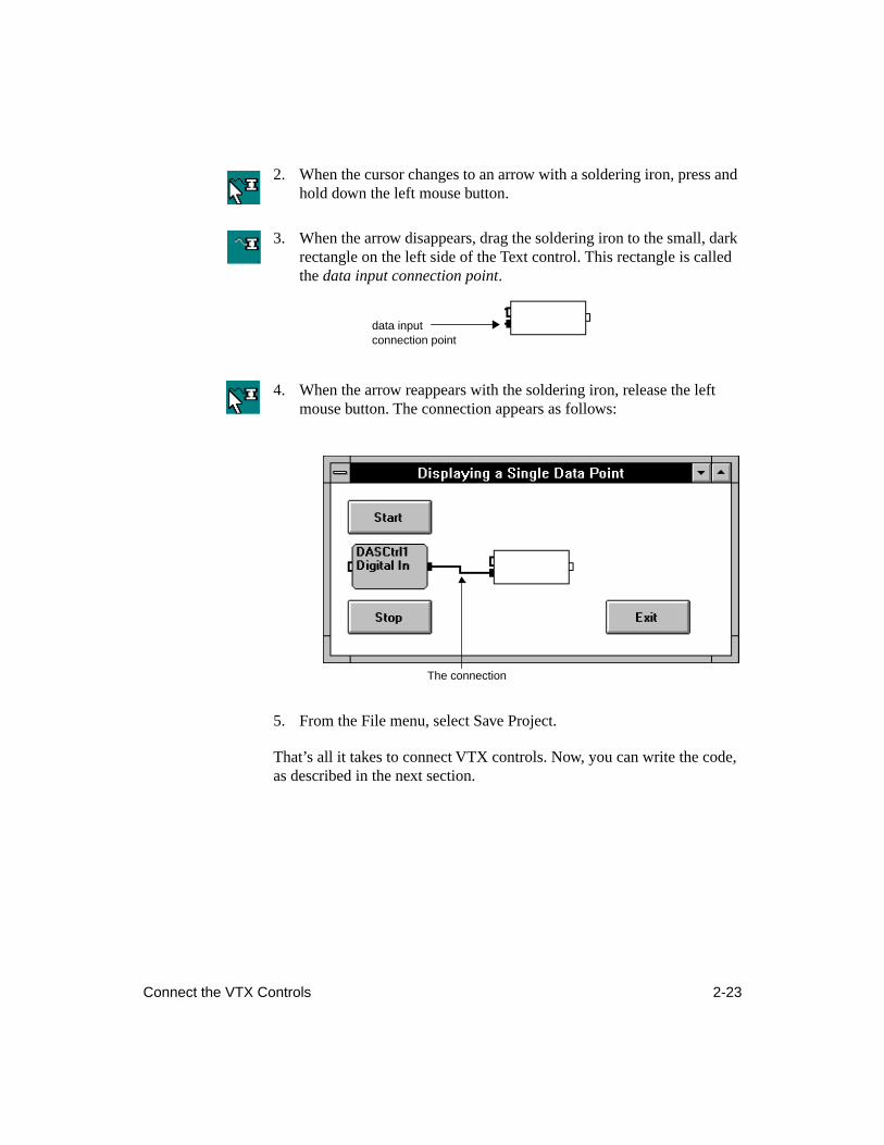
Connect the VTX Controls 2-23
2. When the cursor changes to an arrow with a soldering iron, press and hold down the left mouse button.
3. When the arrow disappears, drag the soldering iron to the small, dark rectangle on the left side of the Text control. This rectangle is called the
data input connection point
.
4. When the arrow reappears with the soldering iron, release the left mouse button. The connection appears as follows:
5. From the File menu, select Save Project.
That’s all it takes to connect VTX controls. Now, you can write the code, as described in the next section.
data input connection point
The connection
2-24 Creating Your First VTX Application
Write the Code
While you could create and run this application without the command buttons, the buttons and writing simple code for them is included here to show you how to integrate tasks performed by VTX controls with the Visual Basic components of a user interface. The VTX Text control is part of the user interface; however, only a connection is required to integrate it with the DAS control. The DAS control passes the data point to the Text control, which displays the data point, without the need for code. However, to start the DAS control and allow the users of the application to decide when to start it, this example includes Visual Basic command buttons.
When a user clicks a command button, the button performs one or more actions, such as starting the DAS control, by executing code in its Click event procedure. Code can include assignment statements that set properties based on user input and/or functions that perform specific actions for a control. For purposes of this tutorial, you will use assignment statements. “VTX Functions” on page 4-17 explains the functions available for VTX controls. The online help for the functions provides detailed examples of using them.
In any assignment statement you must use the name of the VTX control and the name of the property. Depending on how many forms you are using, you may also need to include the name of the form on which you placed the VTX control. For example, to set the ArmState property of a DAS control to Ignore Control Connection, use the following assignment statement:
[VTXForm.]DASCtrl1.ArmState = 1’Ignore Control Connection
In this assignment statement, the text following the apostrophe (
’
) is a comment that explains the meaning of the property setting (1).
To enable the users of this example application to start the digital input operation, you will add code to the Click event procedure of the Start command button. Similarly, to enable users to prevent the VTX controls from starting again, you will add code to the Click event procedure of the Stop command button. Finally, to let users exit the application gracefully, you will add code to the Click event procedure of the Exit command button.
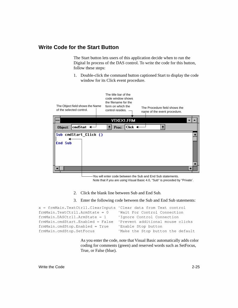
Write the Code 2-25
Write Code for the Start Button
The Start button lets users of this application decide when to run the Digital In process of the DAS control. To write the code for this button, follow these steps:
1. Double-click the command button captioned Start to display the code window for its Click event procedure.
2. Click the blank line between Sub and End Sub.
3. Enter the following code between the Sub and End Sub statements:
x = frmMain.TextCtrl1.ClearInputs 'Clear data from Text controlfrmMain.TextCtrl1.ArmState = 0 'Wait For Control ConnectionfrmMain.DASCtrl1.ArmState = 1 'Ignore Control ConnectionfrmMain.cmdStart.Enabled = False 'Prevent additional mouse clicksfrmMain.cmdStop.Enabled = True 'Enable Stop buttonfrmMain.cmdStop.SetFocus 'Make the Stop button the default
As you enter the code, note that Visual Basic automatically adds color coding for comments (green) and reserved words such as SetFocus, True, or False (blue).
You will enter code between the Sub and End Sub statements.Note that if you are using Visual Basic 4.0, "Sub" is preceded by "Private’.
The Object field shows the Name of the selected control.
The title bar of the code window shows the filename for the form on which the control resides.
The Procedure field shows the name of the event procedure.
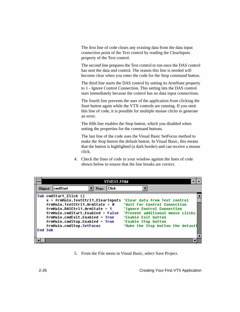
2-26 Creating Your First VTX Application
The first line of code clears any existing data from the data input connection point of the Text control by reading the ClearInputs property of the Text control.
The second line prepares the Text control to run once the DAS control has sent the data and control. The reason this line is needed will become clear when you enter the code for the Stop command button.
The third line starts the DAS control by setting its ArmState property to 1 - Ignore Control Connection. This setting lets the DAS control start immediately because the control has no data input connections.
The fourth line prevents the user of the application from clicking the Start button again while the VTX controls are running. If you omit this line of code, it is possible for multiple mouse clicks to generate an error.
The fifth line enables the Stop button, which you disabled when setting the properties for the command buttons.
The last line of the code uses the Visual Basic SetFocus method to make the Stop button the default button. In Visual Basic, this means that the button is highlighted (a dark border) and can receive a mouse click.
4. Check the lines of code in your window against the lines of code shown below to ensure that the line breaks are correct.
5. From the File menu in Visual Basic, select Save Project.
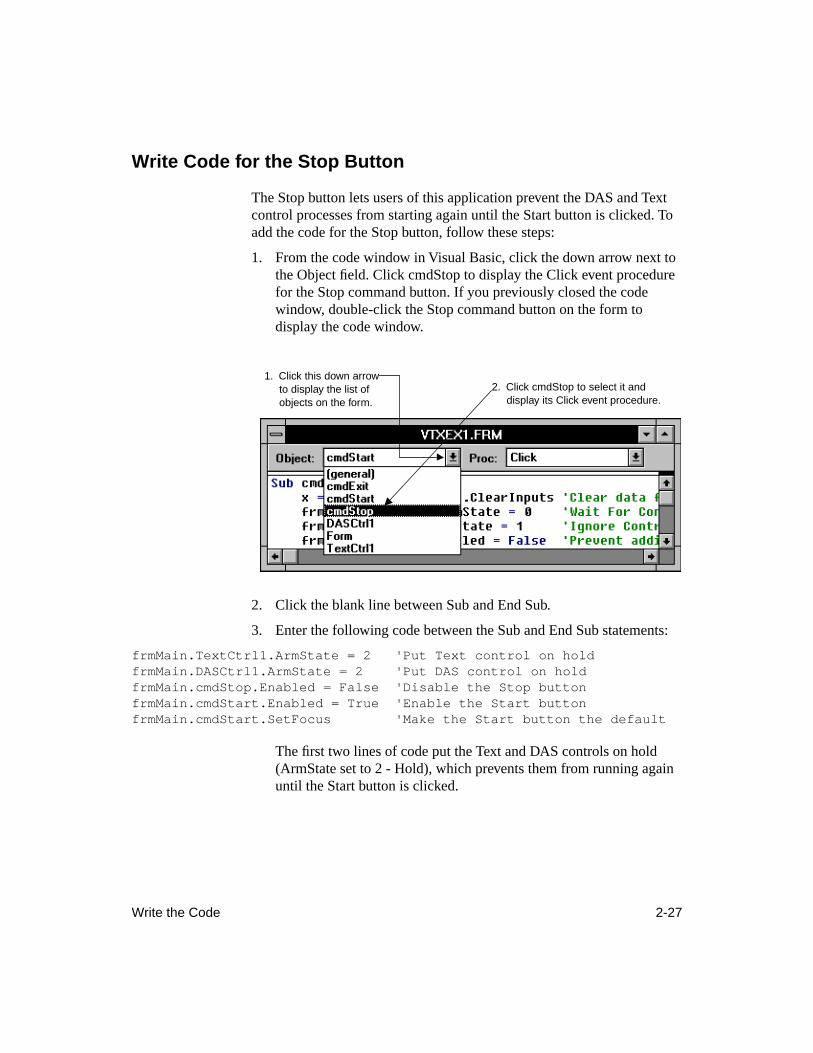
Write the Code 2-27
Write Code for the Stop Button
The Stop button lets users of this application prevent the DAS and Text control processes from starting again until the Start button is clicked. To add the code for the Stop button, follow these steps:
1. From the code window in Visual Basic, click the down arrow next to the Object field. Click cmdStop to display the Click event procedure for the Stop command button. If you previously closed the code window, double-click the Stop command button on the form to display the code window.
2. Click the blank line between Sub and End Sub.
3. Enter the following code between the Sub and End Sub statements:
frmMain.TextCtrl1.ArmState = 2 'Put Text control on holdfrmMain.DASCtrl1.ArmState = 2 'Put DAS control on holdfrmMain.cmdStop.Enabled = False 'Disable the Stop buttonfrmMain.cmdStart.Enabled = True 'Enable the Start buttonfrmMain.cmdStart.SetFocus 'Make the Start button the default
The first two lines of code put the Text and DAS controls on hold (ArmState set to 2 - Hold), which prevents them from running again until the Start button is clicked.
1. Click this down arrow to display the list of objects on the form.
2. Click cmdStop to select it and display its Click event procedure.
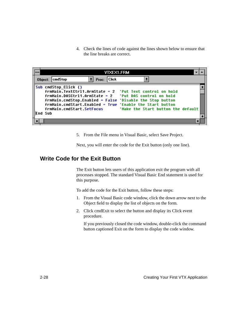
2-28 Creating Your First VTX Application
4. Check the lines of code against the lines shown below to ensure that the line breaks are correct.
5. From the File menu in Visual Basic, select Save Project.
Next, you will enter the code for the Exit button (only one line).
Write Code for the Exit Button
The Exit button lets users of this application exit the program with all processes stopped. The standard Visual Basic End statement is used for this purpose.
To add the code for the Exit button, follow these steps:
1. From the Visual Basic code window, click the down arrow next to the Object field to display the list of objects on the form.
2. Click cmdExit to select the button and display its Click event procedure.
If you previously closed the code window, double-click the command button captioned Exit on the form to display the code window.
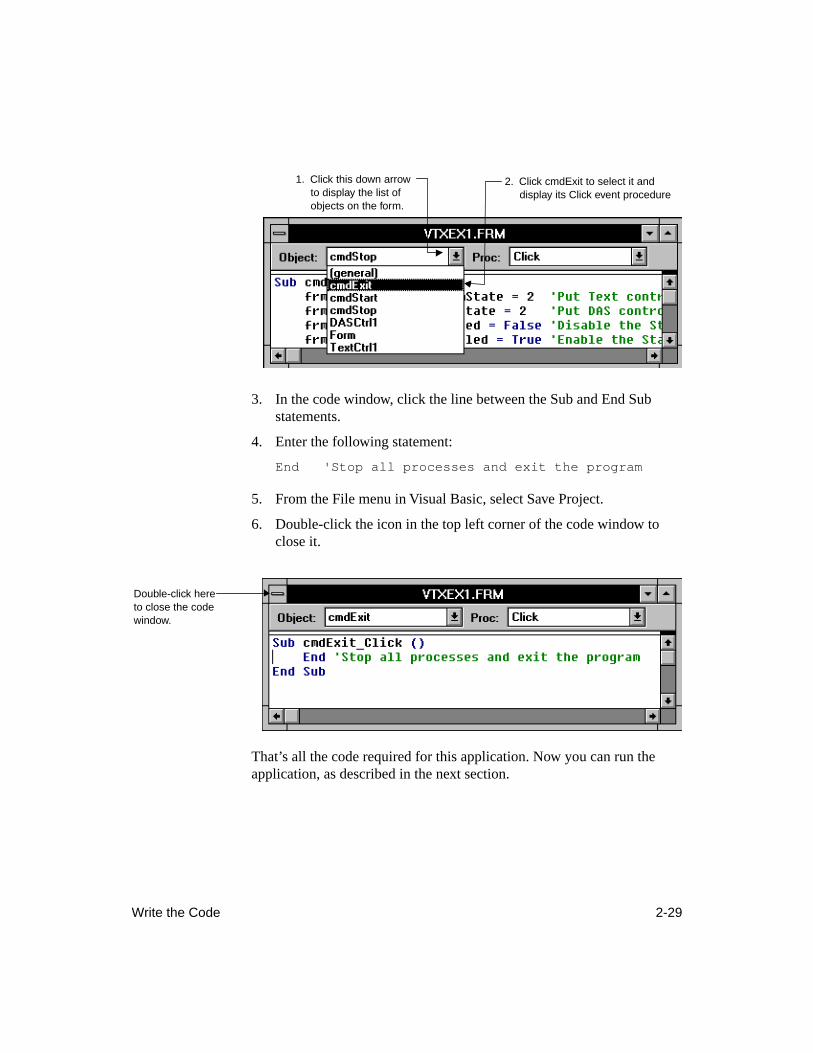
Write the Code 2-29
3. In the code window, click the line between the Sub and End Sub statements.
4. Enter the following statement:
End 'Stop all processes and exit the program
5. From the File menu in Visual Basic, select Save Project.
6. Double-click the icon in the top left corner of the code window to close it.
That’s all the code required for this application. Now you can run the application, as described in the next section.
1. Click this down arrow to display the list of objects on the form.
2. Click cmdExit to select it and display its Click event procedure
Double-click here to close the code window.
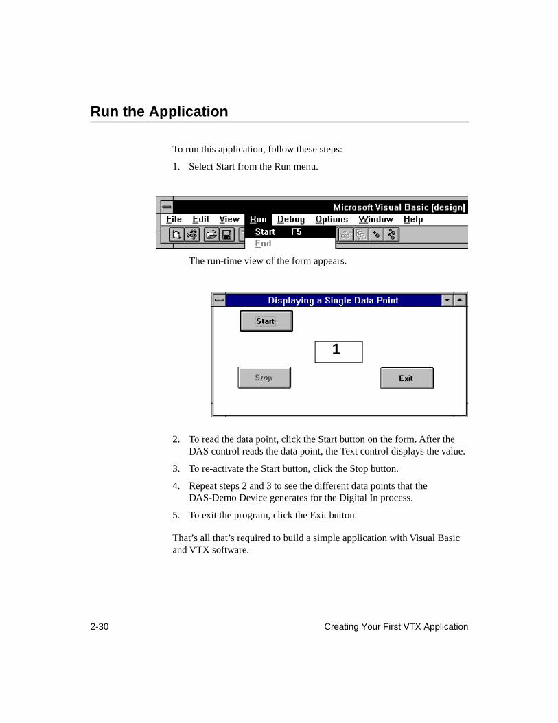
2-30 Creating Your First VTX Application
Run the Application
To run this application, follow these steps:
1. Select Start from the Run menu.
The run-time view of the form appears.
2. To read the data point, click the Start button on the form. After the DAS control reads the data point, the Text control displays the value.
3. To re-activate the Start button, click the Stop button.
4. Repeat steps 2 and 3 to see the different data points that the DAS-Demo Device generates for the Digital In process.
5. To exit the program, click the Exit button.
That’s all that’s required to build a simple application with Visual Basic and VTX software.
1
What’s Next 2-31
What’s Next
Now that you’ve experimented with a simple VTX application, refer to Chapter 3, "VTX System Overview," for more details on how the VTX software works.
Chapter 4, "Building an Application with VTX," provides additional detail on creating applications with VTX controls and Visual Basic. You may want to refer to the chapter as you build your own, more complex applications.
For assistance while you work in Visual Basic, you can select a VTX control and press
F1
to display the VTX help for the VTX control. You can also select a VTX property in the Properties window or More Properties window and press F1 to display help for the property (context-sensitive help). For properties that you can use in code, each property help topic provides a code example. Context-sensitive help is also available for VTX events; to access the help, select the event in the code window and press F1. For VTX functions, use the Search button in the button bar at the top of the help window.
You may also want to refer to the example programs that accompany your VTX software. The example programs fall into two categories:
● Building blocks — These simple applications use two or three VTX controls to perform simple tasks, such as graphing analog input data in a line chart. These examples use Visual Basic command buttons to let users of the application decide when to run the tasks.
● Complex examples — The more complex examples use a combination of three or more VTX controls with standard Visual Basic controls to illustrate how to design a user interface that lets users of the application set the parameters for operations that the VTX controls perform, such as an analog input operation.
The complex example programs have corresponding icons in the Keithley VTX program window; you can double-click the icons to open the projects and Visual Basic. The building block applications do not have icons in the window. You can access all VTX example programs by using the Open Project option in the File menu of Visual Basic. By default, the project files for the example programs are located in the
2-32 Creating Your First VTX Application
VTX\EXAMPLES directory. You can copy and paste code from these programs if the code suits your needs.
For brief descriptions of the building block example programs, click the Examples help icon (yellow question mark) in the Keithley VTX program window. This help file and the example topics are also accessible from the main menu of the VTX system overview help.
You can find more code examples in the online help. The help topic for each VTX control property or function provides a code example. You can copy the code from the Examples window and paste it into your Visual Basic application.
The VTX Environment 3-1
3
Understanding the VTX System
This chapter presents the basic concepts of the VTX system and describes the software tools that the system provides. You have already seen some of these concepts at work in the tutorial in Chapter 2. Before building complex applications, ensure that you understand all of the concepts presented here.
Note:
Depending on the VTX modules you purchased, the references to the Computation, Frequency, Statistics, and Graph controls may not apply
to your VTX system.
The VTX Environment
VTX is a system of software tools that enables you to build complete data acquisition applications through Visual Basic for Windows. These tools include an
integrated
set of custom controls; when placed on a Visual Basic form, VTX controls can pass data and program control among one another without requiring any code. To enable the controls to communicate in this way, the VTX software tools also include the ability to draw connections (or
wires
) between VTX controls.
The integration of the VTX controls creates the VTX
environment
, where you can develop applications according to your data acquisition needs. You can quickly put together simple applications using VTX controls and connections only. For example, you can acquire temperature and pressure data, and display or graph that data immediately; your development can remain entirely within the VTX environment.

3-2 Understanding the VTX System
For complex applications, the VTX environment is open and completely compatible with Visual Basic. You can easily transfer data and program control to and from VTX, using standard Visual Basic programming techniques. Complex applications sometimes require a custom user interface that is supported by data acquisition, error checking, analysis, and graphing tasks.
You can develop the supporting tasks (data acquisition, error checking, analysis) for a complex application within the VTX environment and then use a combination of the following controls to develop the user interface:
●
VTX Graph control
●
VTX Text control
●
Standard Visual Basic controls, such as the command button
●
Third-party custom controls developed for use with Visual Basic
To integrate the tasks in the VTX environment with the user interface, you can set properties and pass program control in the appropriate code modules of the standard Visual Basic and VTX controls. As illustrated in the tutorial in Chapter 2, you can use the Click event procedure of a command button to start an operation that you have configured with a VTX control.
To pass data between the VTX environment and your instruments, you can use the VTX DAS and CTM controls with your Keithley MetraByte data acquisition hardware. The DAS and CTM controls open the VTX environment to your test and measurement hardware by communicating with your data acquisition hardware. See the online help for details on using the DAS and CTM controls.
To pass data between the VTX environment and the Visual Basic environment, you can use the VTX Transfer control. The Transfer control opens the VTX environment for passing data between VTX and Visual Basic arrays, binary DOS files, and Windows spreadsheets. See the online help for details on using the Transfer control.
Processes and Process Sources 3-3
Processes and Process Sources
VTX controls can perform a variety of operations, including data acquisition, line chart, strip chart, data display, computation, conversion, statistical, Boolean logic, filtering, and Fast Fourier Transform operations. In the VTX environment, these operations are called
processes
. The hardware and software resources installed in your computer that perform these operations are called
process sources
.
For example, the DAS control provides four processes that correspond to the following types of data acquisition operations:
●
Analog input operations (Analog In process)
●
Analog output operations (Analog Out process)
●
Digital input operations (Digital In process)
●
Digital output operations (Digital Out process)
Similarly, the CTM control provides three processes that correspond to the types of operations that counter/timer boards can perform:
●
Counter/Timer process, for running event counting, frequency measurement, and pulse generation operations
●
Digital In and Digital Out processes for running single-point digital input and single-point digital output operations
The process sources for the DAS and CTM controls include the Keithley MetraByte hardware and software installed in your computer, such as a DAS-1802HC board and its related software driver or a CTM-05/A board and its related software driver.
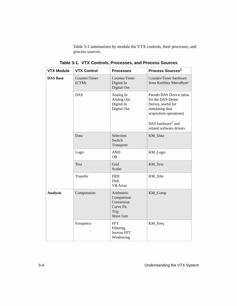
3-4 Understanding the VTX System
Table 3-1 summarizes by module the VTX controls, their processes, and process sources.
Table 3-1. VTX Controls, Processes, and Process Sources
VTX Module VTX Control Processes Process Sources
1
DAS Base
Counter/Timer (CTM)
Counter/TimerDigital InDigital Out
Counter/Timer hardware from Keithley MetraByte
2
DAS Analog InAnalog OutDigital InDigital Out
Pseudo DAS Device (alias for the DAS-Demo Device, useful for simulating data acquisition operations)
DAS hardware
2
and related software drivers
Data SelectionSwitchTranspose
KM_Data
Logic ANDOR
KM_Logic
Text GridScalar
KM_Text
Transfer DDEDiskVB Array
KM_Xfer
Analysis
Computation ArithmeticComparisonConversionCurve FitTrigWave Gen
KM_Comp
Frequency FFTFilteringInverse FFTWindowing
KM_Freq
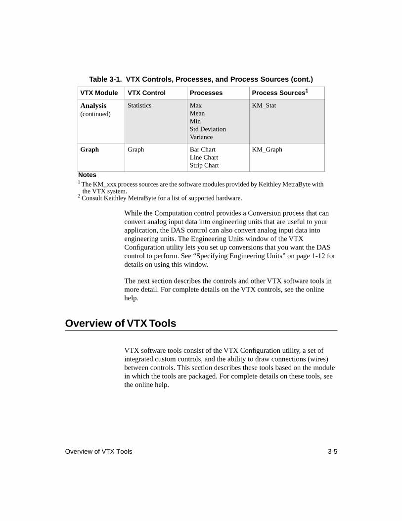
Overview of VTX Tools 3-5
While the Computation control provides a Conversion process that can convert analog input data into engineering units that are useful to your application, the DAS control can also convert analog input data into engineering units. The Engineering Units window of the VTX Configuration utility lets you set up conversions that you want the DAS control to perform. See “Specifying Engineering Units” on page 1-12 for details on using this window.
The next section describes the controls and other VTX software tools in more detail. For complete details on the VTX controls, see the online help.
Overview of VTX Tools
VTX software tools consist of the VTX Configuration utility, a set of integrated custom controls, and the ability to draw connections (wires) between controls. This section describes these tools based on the module in which the tools are packaged. For complete details on these tools, see the online help.
Analysis
(continued)
Statistics MaxMeanMinStd DeviationVariance
KM_Stat
Graph
Graph Bar ChartLine ChartStrip Chart
KM_Graph
Notes
1
The KM_xxx process sources are the software modules provided by Keithley MetraByte with the VTX system.
2
Consult Keithley MetraByte for a list of supported hardware.
Table 3-1. VTX Controls, Processes, and Process Sources (cont.)
VTX Module VTX Control Processes Process Sources
1
3-6 Understanding the VTX System
The
DAS Base Module
provides the following software tools:
●
CTM Control — Lets you set up and run counter/timer operations such as event counting, frequency measurement, and pulse generation with counter/timer hardware such as the Keithley MetraByte CTM-05/A and CTM-10 boards. The CTM control lets you synchronize the start of one to five counter/timer operations. In addition, the CTM control supports single-point digital input and digital output operations.
●
DAS Control — Lets you set up and run data acquisition operations (analog input, analog output, digital input, and digital output). For analog input operations, the DAS control can also convert analog input data into engineering units that are useful to your application. For digital I/O operations, the DAS control also provides a bit mask that lets you control the valid numerical range and interpretation of digital input data and the interpretation of digital output data.
●
Data Control — Lets you manipulate data within the VTX environment. You can select subsets of data or transpose data sets and data elements. The Switch process lets you route data within the VTX environment from one source to multiple destinations or from multiple sources to one destination.
●
Logic Control — Lets you conduct Boolean AND and OR operations based on program control events in the VTX environment. The OR process sends out the number of the input connection point that caused the Logic control to run; you can use that information with other VTX controls.
●
Text Control — Lets you display, create, and modify data within the VTX environment. As you have seen in Chapter 2, the Text control Scalar process provides a text-box-like display for single data points. The Grid process provides a spreadsheet-like display for data sets with one or more data elements.
●
Transfer Control— Lets you move data between the VTX environment and Visual Basic arrays, binary DOS files, or Windows spreadsheets.
●
Connections— Enable VTX controls to pass program control and data among one another. See the section “Program Control in the VTX Environment” on page 3-16 and the online help for more information.
Overview of VTX Tools 3-7
●
VTX Configuration Utility — Provides the following configuration windows:
– DAS Hardware - Lets you register and configure the Keithley MetraByte hardware you want to use with the DAS and CTM controls. Also for specifying the equations or sensors (engineering units) to use in converting data during analog input operations. See “Preparing to Use Boards with VTX Software” on page 1-6 or the online help for instructions on using this utility.
– Keithley Memory Manager - Lets you allocate system memory when using the VTX system to build data acquisition applications. See “Reserving Memory” on page 1-15 or the online help for details.
– VTX Options - Lets you specify options for the VTX programming environment. See “Enabling and Disabling VTX Options” on page 4-41 or the online help for instructions.
●
DAS-Demo Device— Lets you simulate data acquisition operations for the DAS control. You can build an application without installing a DAS board and simulate the data acquisition part of the application with the DAS-Demo Device. In the Properties window, the DAS-Demo Device is listed by its alias, Pseudo DAS Device.
The
Analysis
Module provides the following additional custom controls:
●
Computation control - For generating waveforms and performing a variety of mathematical operations on data passed from other VTX controls, including arithmetic, comparison, conversion, curve fitting, trigonometry, and waveform generation.
●
Frequency control - For performing Fast Fourier Transform (FFT), Inverse FFT, filtering, and windowing operations on data passed from other VTX controls.
●
Statistics control - For calculating maximum, minimum, mean, standard deviation, and variance values on data passed from other VTX controls.
The
Graph Module
provides the Graph control. The Graph control lets you create line or scatter charts, strip charts, and bar charts using data passed from other VTX controls.
3-8 Understanding the VTX System
Properties of VTX Controls
In using the tutorial in Chapter 2, you saw that VTX controls have two sets of properties: those in the Properties window and those in the More Properties window. The properties available in the Properties window are common to all VTX controls and include some standard Visual Basic properties; these properties are referred to as
control
properties. The properties available in the More Properties window are specific to the operation as specified with the VTX ProcessSrc (process source) and Process properties in the Properties window; these properties are referred to as
operation-specific
properties. The following subsections describe these two sets of properties in more detail.
Control Properties
Every VTX control has the same set of
control
properties that appear in the Properties window. Control properties include standard Visual Basic properties such as BackColor, Caption, ForeColor, Name, TabIndex, TabStop, Tag, and Top, as well as properties specific to the VTX controls. VTX controls have some additional control properties that are available only at run time.
Figure 3-1 shows an example of the Properties window for the DAS control as it appears in Visual Basic 3.0; in Visual Basic 4.0, the window does not have the Settings Box at the top. In Figure 3-1, the arrows point to properties that are specific to VTX controls. All other properties are standard Visual Basic properties that appear for the VTX controls.
Note:
Certain standard Visual Basic properties, such as BackColor, ForeColor, TabIndex, and TabStop, determine the appearance or operation of a control at run time. The VTX Text control uses these properties at run
time. However, all other VTX controls ignore these properties.
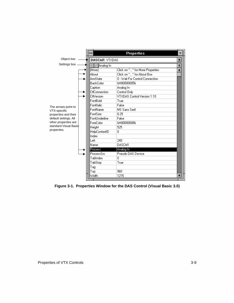
Properties of VTX Controls 3-9
Figure 3-1. Properties Window for the DAS Control (Visual Basic 3.0)
Settings box
Object box
The arrows point to VTX-specific properties and their default settings. All other properties are standard Visual Basic properties.
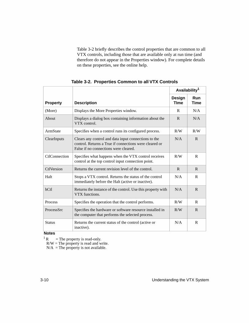
3-10 Understanding the VTX System
Table 3-2 briefly describes the control properties that are common to all VTX controls, including those that are available only at run time (and therefore do not appear in the Properties window). For complete details on these properties, see the online help.
Table 3-2. Properties Common to all VTX Controls
Availability
1
Notes
1
R = The property is read-only.R/W = The property is read and write.N/A = The property is not available.
Property DescriptionDesign TIme
Run Time
(More) Displays the More Properties window. R N/A
About Displays a dialog box containing information about the VTX control.
R N/A
ArmState Specifies when a control runs its configured process. R/W R/W
ClearInputs Clears any control and data input connections to the control. Returns a True if connections were cleared or False if no connections were cleared.
N/A R
CtlConnection Specifies what happens when the VTX control receives control at the top control input connection point.
R/W R
CtlVersion Returns the current revision level of the control. R R
Halt Stops a VTX control. Returns the status of the control immediately before the Halt (active or inactive).
N/A R
hCtl Returns the instance of the control. Use this property with VTX functions.
N/A R
Process Specifies the operation that the control performs. R/W R
ProcessSrc Specifies the hardware or software resource installed in the computer that performs the selected process.
R/W R
Status Returns the current status of the control (active or inactive).
N/A R
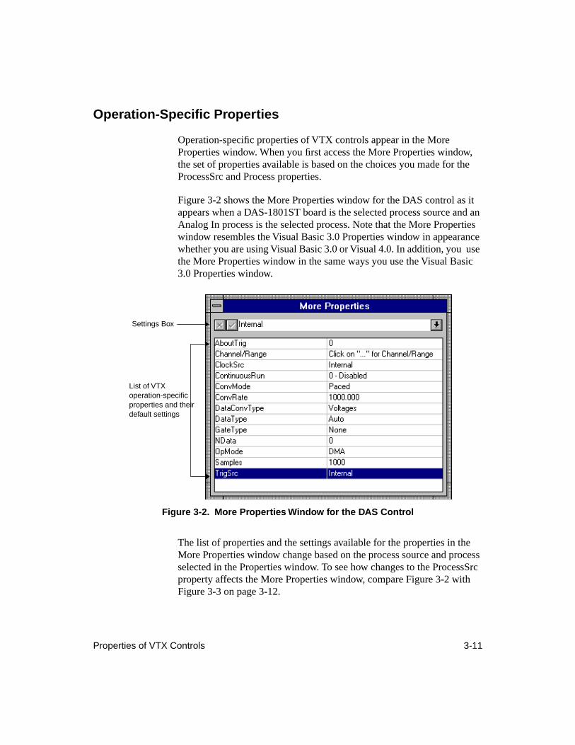
Properties of VTX Controls 3-11
Operation-Specific Properties
Operation-specific properties of VTX controls appear in the More Properties window. When you first access the More Properties window, the set of properties available is based on the choices you made for the ProcessSrc and Process properties.
Figure 3-2 shows the More Properties window for the DAS control as it appears when a DAS-1801ST board is the selected process source and an Analog In process is the selected process. Note that the More Properties window resembles the Visual Basic 3.0 Properties window in appearance whether you are using Visual Basic 3.0 or Visual 4.0. In addition, you use the More Properties window in the same ways you use the Visual Basic 3.0 Properties window.
Figure 3-2. More Properties Window for the DAS Control
The list of properties and the settings available for the properties in the More Properties window change based on the process source and process selected in the Properties window. To see how changes to the ProcessSrc property affects the More Properties window, compare Figure 3-2 with Figure 3-3 on page 3-12.
Settings Box
List of VTX operation-specific properties and their default settings
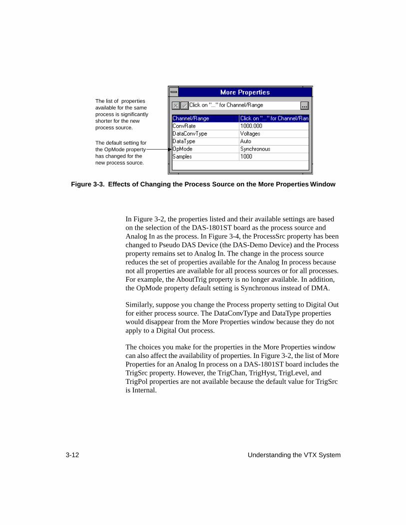
3-12 Understanding the VTX System
Figure 3-3. Effects of Changing the Process Source on the More Properties Window
In Figure 3-2, the properties listed and their available settings are based on the selection of the DAS-1801ST board as the process source and Analog In as the process. In Figure 3-4, the ProcessSrc property has been changed to Pseudo DAS Device (the DAS-Demo Device) and the Process property remains set to Analog In. The change in the process source reduces the set of properties available for the Analog In process because not all properties are available for all process sources or for all processes. For example, the AboutTrig property is no longer available. In addition, the OpMode property default setting is Synchronous instead of DMA.
Similarly, suppose you change the Process property setting to Digital Out for either process source. The DataConvType and DataType properties would disappear from the More Properties window because they do not apply to a Digital Out process.
The choices you make for the properties in the More Properties window can also affect the availability of properties. In Figure 3-2, the list of More Properties for an Analog In process on a DAS-1801ST board includes the TrigSrc property. However, the TrigChan, TrigHyst, TrigLevel, and TrigPol properties are not available because the default value for TrigSrc is Internal.
The list of properties available for the same process is significantly shorter for the new process source.
The default setting for the OpMode property has changed for the new process source.
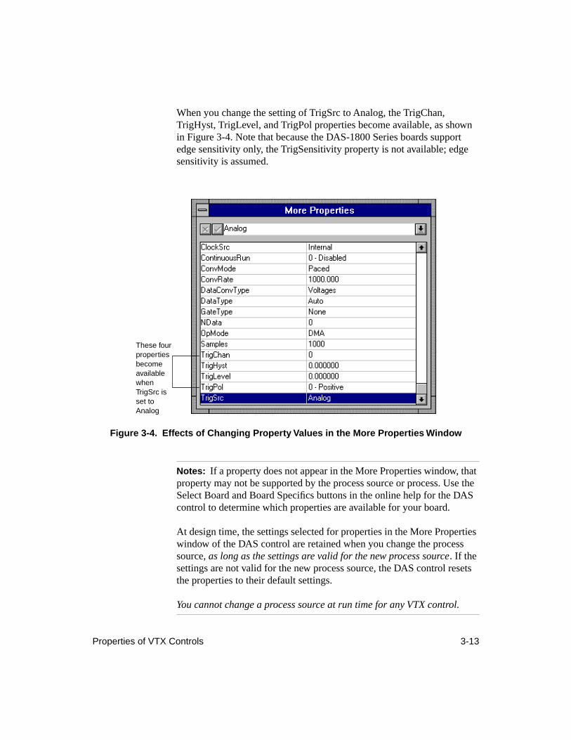
Properties of VTX Controls 3-13
When you change the setting of TrigSrc to Analog, the TrigChan, TrigHyst, TrigLevel, and TrigPol properties become available, as shown in Figure 3-4. Note that because the DAS-1800 Series boards support edge sensitivity only, the TrigSensitivity property is not available; edge sensitivity is assumed.
Figure 3-4. Effects of Changing Property Values in the More Properties Window
Notes:
If a property does not appear in the More Properties window, that property may not be supported by the process source or process. Use the Select Board and Board Specifics buttons in the online help for the DAS control to determine which properties are available for your board.
At design time, the settings selected for properties in the More Properties window of the DAS control are retained when you change the process source,
as long as the settings are valid for the new process source
. If the settings are not valid for the new process source, the DAS control resets the properties to their default settings.
You cannot change a process source at run time for any VTX control.
These four properties become available when TrigSrc is set to Analog
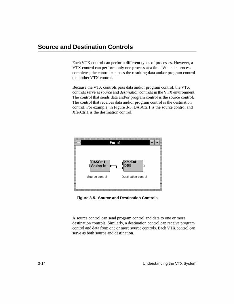
3-14 Understanding the VTX System
Source and Destination Controls
Each VTX control can perform different types of processes. However, a VTX control can perform only one process at a time. When its process completes, the control can pass the resulting data and/or program control to another VTX control.
Because the VTX controls pass data and/or program control, the VTX controls serve as
source
and
destination
controls in the VTX environment. The control that sends data and/or program control is the source control. The control that receives data and/or program control is the destination control. For example, in Figure 3-5, DASCtrl1 is the source control and XferCtrl1 is the destination control.
Figure 3-5. Source and Destination Controls
A source control can send program control and data to one or more destination controls. Similarly, a destination control can receive program control and data from one or more source controls. Each VTX control can serve as both source and destination.
Source control Destination control
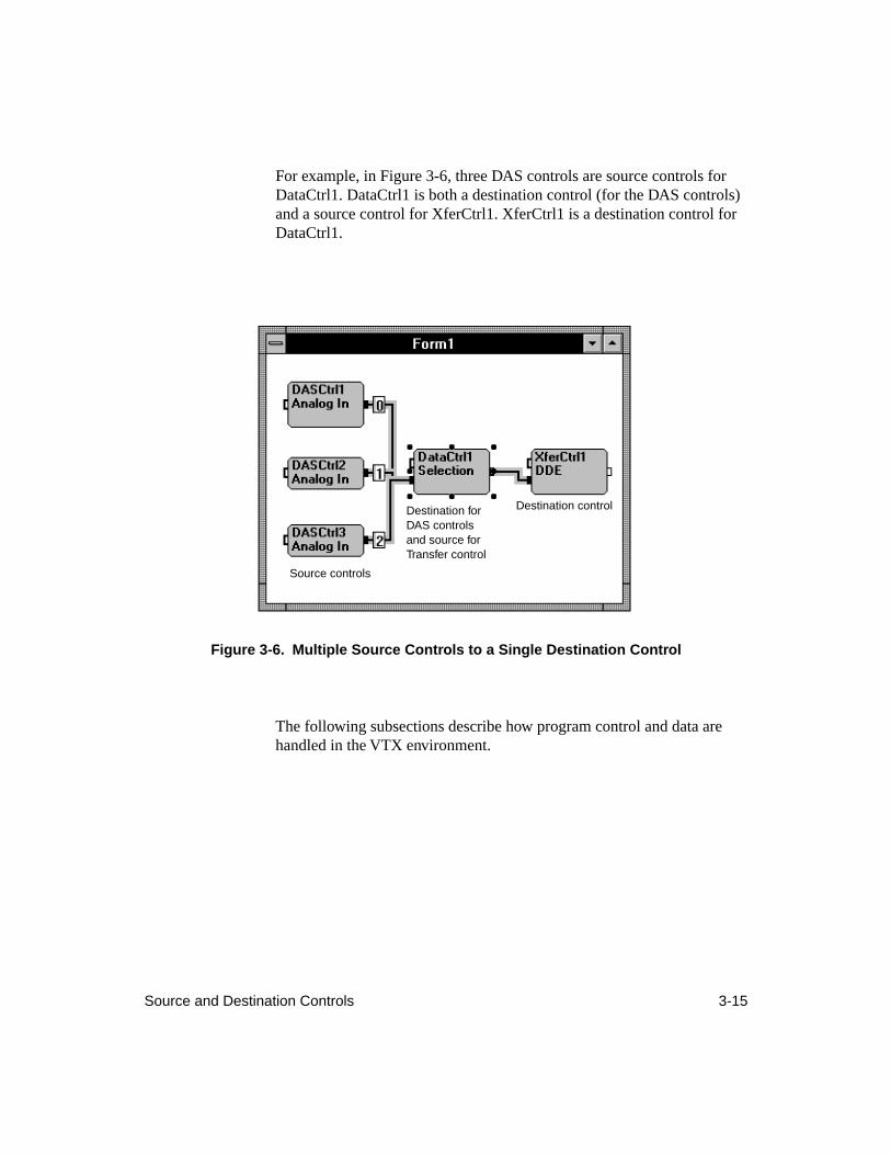
Source and Destination Controls 3-15
For example, in Figure 3-6, three DAS controls are source controls for DataCtrl1. DataCtrl1 is both a destination control (for the DAS controls) and a source control for XferCtrl1. XferCtrl1 is a destination control for DataCtrl1.
Figure 3-6. Multiple Source Controls to a Single Destination Control
The following subsections describe how program control and data are handled in the VTX environment.
Source controls
Destination controlDestination for DAS controls and source for Transfer control
3-16 Understanding the VTX System
Program Control in the VTX Environment
Setting up program control for an application generally refers to specifying the order in which the tasks in an application are performed. In the VTX environment, each VTX process is a task that the application performs, and program control is referred to as simply
control
. To specify the order in which tasks are performed in your VTX application, you set up the VTX controls to pass
control
from a source control to a destination control.
In the VTX environment,
control
tells the destination control to start its configured process. Depending on the requirements of the application, VTX controls can pass control only or they can pass control with data. Note that VTX controls always pass control when passing data. Control passes from a source control to a destination control through a control
connection
. In the VTX environment, a connection is a line (or
wire
) that you draw between the controls. See “Connections” on page 3-20 for more information.
The VTX Logic control provides an additional way to specify the order of tasks of an application. With the Logic control, you can perform Boolean operations (OR and AND) based on control passed from source controls to the Logic control. For example, based on the completion of one of three DAS processes (OR), you can send data to a VTX Graph control for plotting or to a VTX Text control for display in a grid. The Logic control can determine which of the three DAS processes completed; you might want to use that information to display a title for the graph or grid.
The VTX Data control provides an additional way to specify the flow of data in an application. Using the Switch process of the Data control, you can route data from one source control to multiple destination controls or from multiple source controls to one destination control.
Data in the VTX Environment
In the VTX environment, you can specify the flow of data between VTX controls. Certain VTX processes let you pass data into and out from the VTX environment. This section describes the structure of data in the VTX environment as well as moving data within, to, and from the VTX environment.
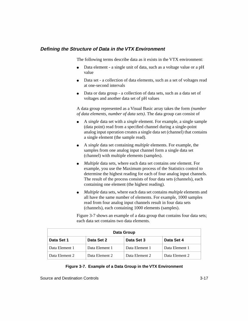
Source and Destination Controls 3-17
Defining the Structure of Data in the VTX Environment
The following terms describe data as it exists in the VTX environment:
●
Data element - a single unit of data, such as a voltage value or a pH value
●
Data set - a collection of data elements, such as a set of voltages read at one-second intervals
●
Data or data group - a collection of data sets, such as a data set of voltages and another data set of pH values
A data group represented as a Visual Basic array takes the form
(number of data elements
,
number of data sets)
. The data group can consist of
●
A
single
data set with a
single
element. For example, a single sample (data point) read from a specified channel during a single-point analog input operation creates a single data set (channel) that contains a single element (the sample read).
●
A single data set containing multiple elements. For example, the samples from one analog input channel form a single data set (channel) with multiple elements (samples).
● Multiple data sets, where each data set contains one element. For example, you use the Maximum process of the Statistics control to determine the highest reading for each of four analog input channels. The result of the process consists of four data sets (channels), each containing one element (the highest reading).
● Multiple data sets, where each data set contains multiple elements and all have the same number of elements. For example, 1000 samples read from four analog input channels result in four data sets (channels), each containing 1000 elements (samples).
Figure 3-7 shows an example of a data group that contains four data sets; each data set contains two data elements.
Figure 3-7. Example of a Data Group in the VTX Environment
Data Group
Data Set 1 Data Set 2 Data Set 3 Data Set 4
Data Element 1 Data Element 1 Data Element 1 Data Element 1
Data Element 2 Data Element 2 Data Element 2 Data Element 2
3-18 Understanding the VTX System
Moving Data between VTX Controls
VTX controls send and receive data within the VTX environment in the combinations of data sets and data elements (single set, single element; single set, multiple elements, and multiple sets, multiple elements). VTX source controls can send only one data group at a time. However, source controls can send the same data group to multiple destination controls; similarly, VTX destination controls can receive data groups from multiple source controls.
When a VTX control receives data groups from multiple sources, that control merges the data sets from all the data groups into a single data group. This operation is called data set appending. Because the VTX control appends data sets, each data set in all the incoming data groups must have the same number of data elements.
Note, however, that the Line Chart process of the VTX Graph control can accept data groups whose data sets contain different numbers of elements. For example, suppose you want to acquire analog input data from two different instruments and graph the data from both instruments in the same line chart. This application requires two DAS controls (one for each analog input operation) and one Graph control. At run time, one analog input operation acquires 100 samples from two channels; the other operation acquires 200 samples from two channels. The data group resulting from the first analog input operation contains two data sets (two channels), each with 100 data elements (samples). The data group resulting from the second analog input operation contains two data sets (two channels), each with 200 data elements (samples). You can send these two data groups to the Graph control for display in the same line chart because the Line Chart process can accept data groups whose data sets contain different numbers of elements.
The Text control lets you create, display, and modify data in scalar, vector, and matrix format within the VTX environment. In addition, any VTX control that produces output data can pass that data in the appropriate format (scalar, vector, or matrix) within the VTX environment.
However, if you pass data out from the VTX environment to a Visual Basic array with the Transfer control, you must always declare a two-dimensional Visual Basic array to receive the data, whether the data is a single value (scalar), a single data set with multiple values, multiple
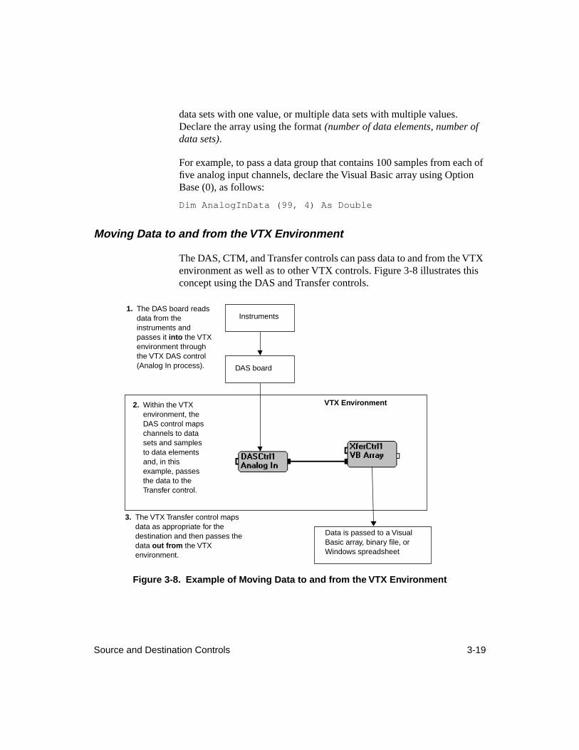
Source and Destination Controls 3-19
data sets with one value, or multiple data sets with multiple values. Declare the array using the format (number of data elements, number of data sets).
For example, to pass a data group that contains 100 samples from each of five analog input channels, declare the Visual Basic array using Option Base (0), as follows:
Dim AnalogInData (99, 4) As Double
Moving Data to and from the VTX Environment
The DAS, CTM, and Transfer controls can pass data to and from the VTX environment as well as to other VTX controls. Figure 3-8 illustrates this concept using the DAS and Transfer controls.
Figure 3-8. Example of Moving Data to and from the VTX Environment
VTX Environment
Data is passed to a Visual Basic array, binary file, or Windows spreadsheet
DAS board
Instruments1. The DAS board reads
data from the instruments and passes it into the VTX environment through the VTX DAS control (Analog In process).
3. The VTX Transfer control maps data as appropriate for the destination and then passes the data out from the VTX environment.
2. Within the VTX environment, the DAS control maps channels to data sets and samples to data elements and, in this example, passes the data to the Transfer control.
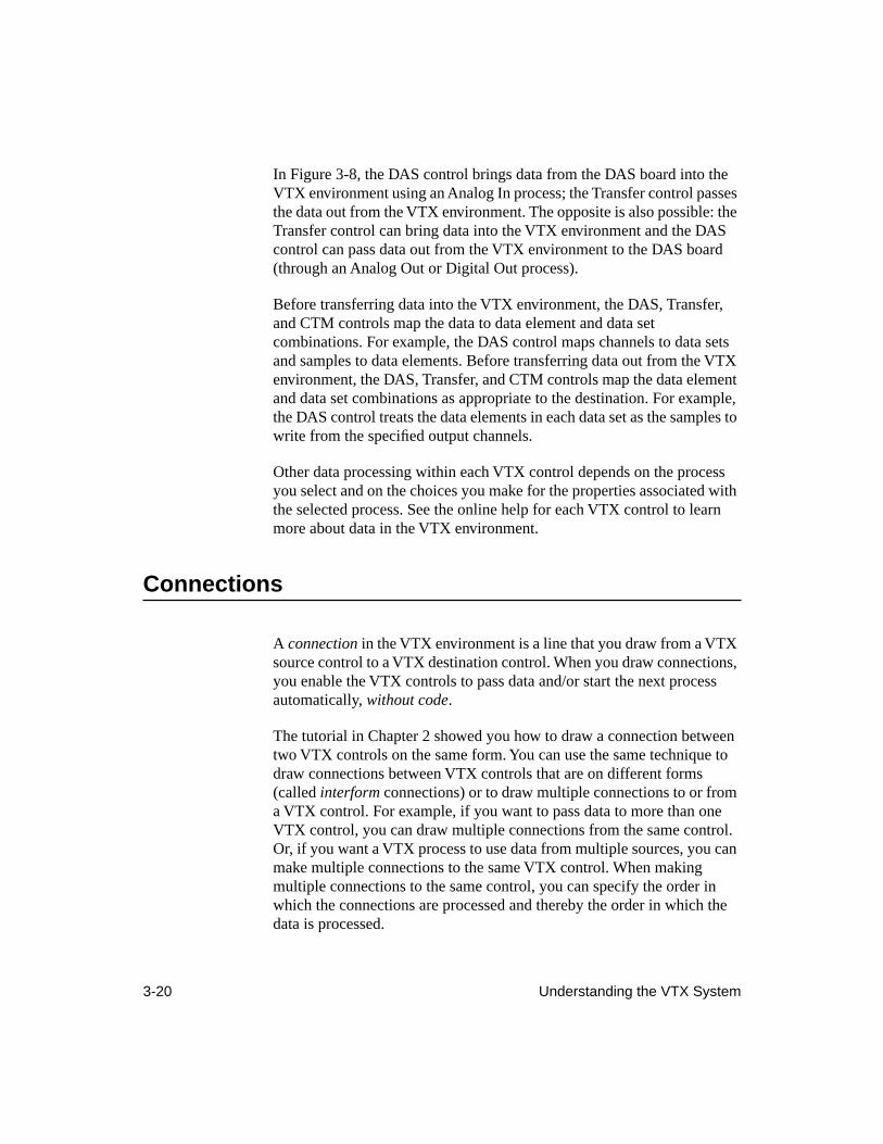
3-20 Understanding the VTX System
In Figure 3-8, the DAS control brings data from the DAS board into the VTX environment using an Analog In process; the Transfer control passes the data out from the VTX environment. The opposite is also possible: the Transfer control can bring data into the VTX environment and the DAS control can pass data out from the VTX environment to the DAS board (through an Analog Out or Digital Out process).
Before transferring data into the VTX environment, the DAS, Transfer, and CTM controls map the data to data element and data set combinations. For example, the DAS control maps channels to data sets and samples to data elements. Before transferring data out from the VTX environment, the DAS, Transfer, and CTM controls map the data element and data set combinations as appropriate to the destination. For example, the DAS control treats the data elements in each data set as the samples to write from the specified output channels.
Other data processing within each VTX control depends on the process you select and on the choices you make for the properties associated with the selected process. See the online help for each VTX control to learn more about data in the VTX environment.
Connections
A connection in the VTX environment is a line that you draw from a VTX source control to a VTX destination control. When you draw connections, you enable the VTX controls to pass data and/or start the next process automatically, without code.
The tutorial in Chapter 2 showed you how to draw a connection between two VTX controls on the same form. You can use the same technique to draw connections between VTX controls that are on different forms (called interform connections) or to draw multiple connections to or from a VTX control. For example, if you want to pass data to more than one VTX control, you can draw multiple connections from the same control. Or, if you want a VTX process to use data from multiple sources, you can make multiple connections to the same VTX control. When making multiple connections to the same control, you can specify the order in which the connections are processed and thereby the order in which the data is processed.
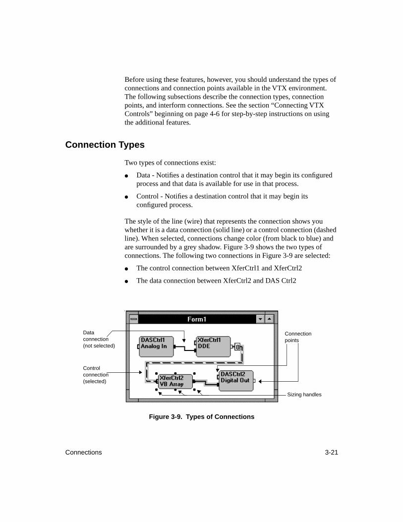
Connections 3-21
Before using these features, however, you should understand the types of connections and connection points available in the VTX environment. The following subsections describe the connection types, connection points, and interform connections. See the section “Connecting VTX Controls” beginning on page 4-6 for step-by-step instructions on using the additional features.
Connection Types
Two types of connections exist:
● Data - Notifies a destination control that it may begin its configured process and that data is available for use in that process.
● Control - Notifies a destination control that it may begin its configured process.
The style of the line (wire) that represents the connection shows you whether it is a data connection (solid line) or a control connection (dashed line). When selected, connections change color (from black to blue) and are surrounded by a grey shadow. Figure 3-9 shows the two types of connections. The following two connections in Figure 3-9 are selected:
● The control connection between XferCtrl1 and XferCtrl2
● The data connection between XferCtrl2 and DAS Ctrl2
Figure 3-9. Types of Connections
Data connection (not selected)
Control connection (selected)
Connection points
Sizing handles
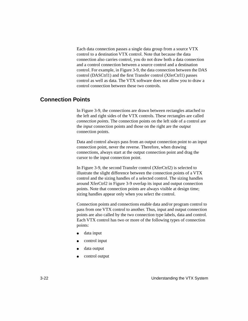
3-22 Understanding the VTX System
Each data connection passes a single data group from a source VTX control to a destination VTX control. Note that because the data connection also carries control, you do not draw both a data connection and a control connection between a source control and a destination control. For example, in Figure 3-9, the data connection between the DAS control (DASCtrl1) and the first Transfer control (XferCtrl1) passes control as well as data. The VTX software does not allow you to draw a control connection between these two controls.
Connection Points
In Figure 3-9, the connections are drawn between rectangles attached to the left and right sides of the VTX controls. These rectangles are called connection points. The connection points on the left side of a control are the input connection points and those on the right are the output connection points.
Data and control always pass from an output connection point to an input connection point, never the reverse. Therefore, when drawing connections, always start at the output connection point and drag the cursor to the input connection point.
In Figure 3-9, the second Transfer control (XferCtrl2) is selected to illustrate the slight difference between the connection points of a VTX control and the sizing handles of a selected control. The sizing handles around XferCtrl2 in Figure 3-9 overlap its input and output connection points. Note that connection points are always visible at design time; sizing handles appear only when you select the control.
Connection points and connections enable data and/or program control to pass from one VTX control to another. Thus, input and output connection points are also called by the two connection type labels, data and control. Each VTX control has two or more of the following types of connection points:
● data input
● control input
● data output
● control output
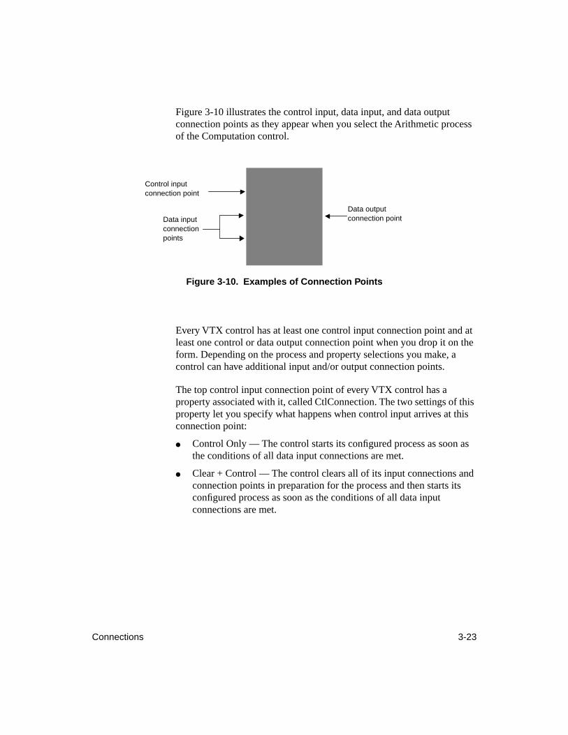
Connections 3-23
Figure 3-10 illustrates the control input, data input, and data output connection points as they appear when you select the Arithmetic process of the Computation control.
Figure 3-10. Examples of Connection Points
Every VTX control has at least one control input connection point and at least one control or data output connection point when you drop it on the form. Depending on the process and property selections you make, a control can have additional input and/or output connection points.
The top control input connection point of every VTX control has a property associated with it, called CtlConnection. The two settings of this property let you specify what happens when control input arrives at this connection point:
● Control Only — The control starts its configured process as soon as the conditions of all data input connections are met.
● Clear + Control — The control clears all of its input connections and connection points in preparation for the process and then starts its configured process as soon as the conditions of all data input connections are met.
Data output connection pointData input
connection points
Control input connection point
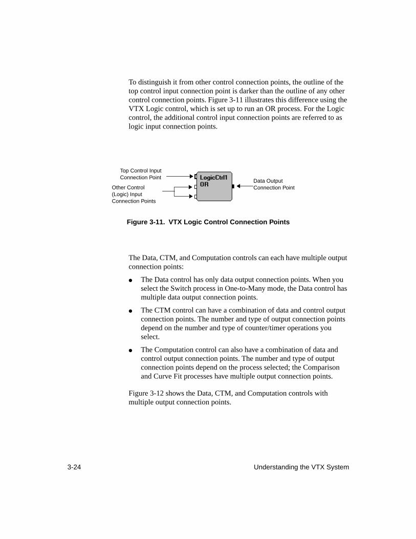
3-24 Understanding the VTX System
To distinguish it from other control connection points, the outline of the top control input connection point is darker than the outline of any other control connection points. Figure 3-11 illustrates this difference using the VTX Logic control, which is set up to run an OR process. For the Logic control, the additional control input connection points are referred to as logic input connection points.
Figure 3-11. VTX Logic Control Connection Points
The Data, CTM, and Computation controls can each have multiple output connection points:
● The Data control has only data output connection points. When you select the Switch process in One-to-Many mode, the Data control has multiple data output connection points.
● The CTM control can have a combination of data and control output connection points. The number and type of output connection points depend on the number and type of counter/timer operations you select.
● The Computation control can also have a combination of data and control output connection points. The number and type of output connection points depend on the process selected; the Comparison and Curve Fit processes have multiple output connection points.
Figure 3-12 shows the Data, CTM, and Computation controls with multiple output connection points.
Data Output Connection PointOther Control
(Logic) Input Connection Points
Top Control Input Connection Point
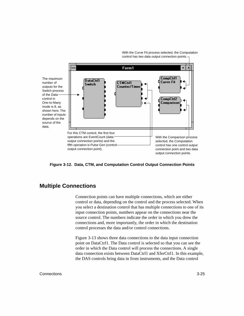
Connections 3-25
Figure 3-12. Data, CTM, and Computation Control Output Connection Points
Multiple Connections
Connection points can have multiple connections, which are either control or data, depending on the control and the process selected. When you select a destination control that has multiple connections to one of its input connection points, numbers appear on the connections near the source control. The numbers indicate the order in which you drew the connections and, more importantly, the order in which the destination control processes the data and/or control connections.
Figure 3-13 shows three data connections to the data input connection point on DataCtrl1. The Data control is selected so that you can see the order in which the Data control will process the connections. A single data connection exists between DataCtrl1 and XferCtrl1. In this example, the DAS controls bring data in from instruments, and the Data control
For this CTM control, the first four operations are EventCount (data output connection points) and the fifth operation is Pulse Gen (control output connection point).
With the Comparison process selected, the Computation control has one control output connection point and two data output connection points.
The maximum number of outputs for the Switch process of the Data control in One-to-Many mode is 8, as shown here. The number of inputs depends on the source of the data.
With the Curve Fit process selected, the Computation control has two data output connection points.
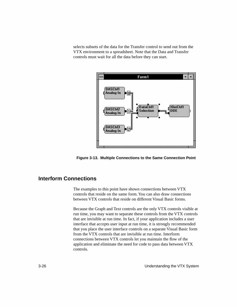
3-26 Understanding the VTX System
selects subsets of the data for the Transfer control to send out from the VTX environment to a spreadsheet. Note that the Data and Transfer controls must wait for all the data before they can start.
Figure 3-13. Multiple Connections to the Same Connection Point
Interform Connections
The examples to this point have shown connections between VTX controls that reside on the same form. You can also draw connections between VTX controls that reside on different Visual Basic forms.
Because the Graph and Text controls are the only VTX controls visible at run time, you may want to separate these controls from the VTX controls that are invisible at run time. In fact, if your application includes a user interface that accepts user input at run time, it is strongly recommended that you place the user interface controls on a separate Visual Basic form from the VTX controls that are invisible at run time. Interform connections between VTX controls let you maintain the flow of the application and eliminate the need for code to pass data between VTX controls.

Connections 3-27
Figure 3-14 illustrates a simple application that separates the VTX controls that are invisible at run time from user interface controls. The interform connection is also invisible at run time.
In Figure 3-14, the interform connection between the Graph control and the Data control is marked by the letter A in a box, called a connection label. All interform connections have connection labels near the source and destination controls. As you create interform connections, the letters are incremented alphabetically. You can draw up to 702 interform connections in a single VTX application.
An interform connection may also have a number near the source control. As with connections on a single form, the number indicates the order in which you draw the connections and the order in which the destination control processes the connection.
Figure 3-14. Example of Interform Connections
Interform connection starts at DataCtrl1
Interform connection ends at GraphCtrl1
Connection label
Connection label
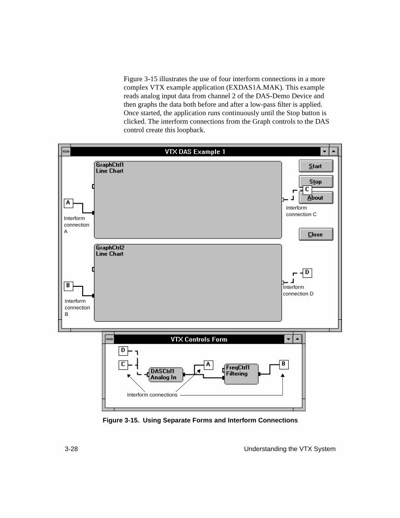
3-28 Understanding the VTX System
Figure 3-15 illustrates the use of four interform connections in a more complex VTX example application (EXDAS1A.MAK). This example reads analog input data from channel 2 of the DAS-Demo Device and then graphs the data both before and after a low-pass filter is applied. Once started, the application runs continuously until the Stop button is clicked. The interform connections from the Graph controls to the DAS control create this loopback.
Figure 3-15. Using Separate Forms and Interform Connections
Interform connection C
Interform connection D
Interform connection A
Interform connection B
Interform connections
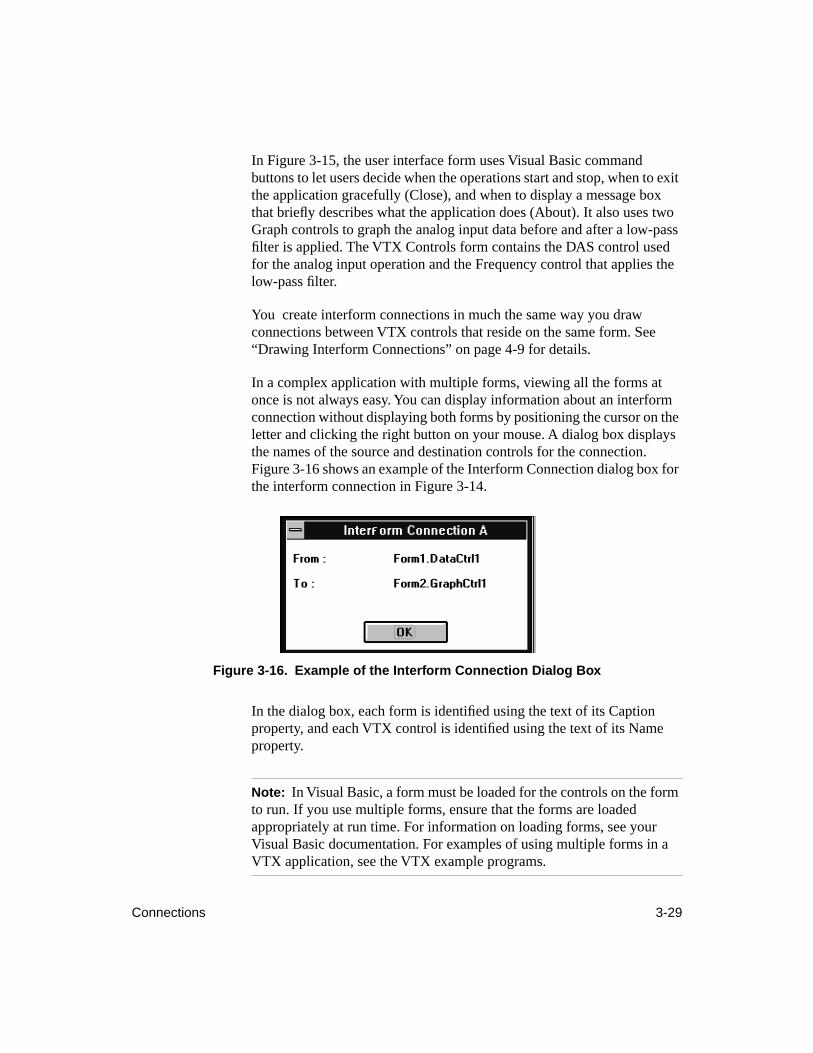
Connections 3-29
In Figure 3-15, the user interface form uses Visual Basic command buttons to let users decide when the operations start and stop, when to exit the application gracefully (Close), and when to display a message box that briefly describes what the application does (About). It also uses two Graph controls to graph the analog input data before and after a low-pass filter is applied. The VTX Controls form contains the DAS control used for the analog input operation and the Frequency control that applies the low-pass filter.
You create interform connections in much the same way you draw connections between VTX controls that reside on the same form. See “Drawing Interform Connections” on page 4-9 for details.
In a complex application with multiple forms, viewing all the forms at once is not always easy. You can display information about an interform connection without displaying both forms by positioning the cursor on the letter and clicking the right button on your mouse. A dialog box displays the names of the source and destination controls for the connection. Figure 3-16 shows an example of the Interform Connection dialog box for the interform connection in Figure 3-14.
Figure 3-16. Example of the Interform Connection Dialog Box
In the dialog box, each form is identified using the text of its Caption property, and each VTX control is identified using the text of its Name property.
Note: In Visual Basic, a form must be loaded for the controls on the form to run. If you use multiple forms, ensure that the forms are loaded appropriately at run time. For information on loading forms, see your Visual Basic documentation. For examples of using multiple forms in a VTX application, see the VTX example programs.
3-30 Understanding the VTX System
Concept Summary
This chapter introduced the concepts that you need to understand to use the VTX system. The online help also provides some of this information; in addition, the online help provides control-specific details. The concepts are summarized as follows:
● Integrated controls - VTX controls can pass data and program control among one another, without requiring you to write any code; you control this communication capability by drawing connections (wires) between the controls.
● VTX environment - The integration of VTX controls creates the VTX environment, where you can develop simple and complex applications. This environment is open and completely compatible with Visual Basic.
● Processes - Operations that the VTX controls can perform.
● Process sources - The hardware or software resources on the computer that perform the operations (processes).
● Control-level properties - Every VTX control has the same set of properties in the Properties window. The choices you make for the Process and ProcessSrc properties determine the availability of properties in the More Properties window.
● Operation-specific properties - Every VTX control has an additional set of properties that appear in the VTX More Properties window. These properties let you set parameters for the selected process and process source.
● Source control - A VTX control that sends data and/or program control.
● Destination control - A VTX control that receives data and/or program control.
● Control - Message that instructs a VTX control that it can start its configured process.
● Data - In the VTX environment, a data element is a single unit of data; a data set consists of one or multiple data elements; and data or a data group consists of multiple data sets.
Concept Summary 3-31
● Connections - Represented visually by lines (wires) drawn between the VTX controls, connections enable control and data to pass from one VTX control to another. Interform connections let you place VTX controls on different forms while maintaining the flow of your application.
● Connection points - The small rectangles on the left and right sides of a VTX control. The connection points on the left side are input connection points; the connection points on the right side are output connection points. When drawing connections, draw the line (wire) from an output connection point to an input connection point.

4-1
4
Building Complex Applications
This chapter describes in detail the major steps in building a complex data acquisition application with the VTX system and Visual Basic. This chapter assumes that you have completed the tutorial in Chapter 2 and understand the concepts explained in Chapter 3. Refer to the online help for a complete reference for VTX properties, events, and functions.
The major steps in building a complex application are similar to those for building a simple application, as follows:
1. Plan the application.
2. Design the user interface for the application.
3. Set properties for all controls.
4. Connect the VTX controls.
5. Write code for the application.
6. Test, debug, and prepare the application for distribution.
Notes:
The instructions in this chapter apply to both Visual Basic 3.0 and the 16-bit versions of Visual Basic 4.0.
The illustrations in this chapter were created using Visual Basic 3.0; differences between the Properties window in Visual Basic 3.0 and 4.0 are noted as appropriate.
The term "code module" applies to Visual Basic 3.0; Visual Basic 4.0 documentation indicates that this term has been replaced by "standard
module" for Visual Basic 4.0. This chapter uses the Visual Basic 3.0 term.
4-2 Building Complex Applications
Planning the Application
Answers to the following questions can guide the plan for a VTX application:
●
What operations does the application perform? For example, if the application acquires data from analog input channels, filters that data with a Fast Fourier Transform operation, and then graphs the results, you will need a DAS control, a Frequency control, and a Graph control.
●
What parameters do the operations require and how are they set? Continuing the example, if the users of the application will decide which analog input channels to sample and how many samples to acquire, the user interface will require controls that accept user input, and code will be needed to pass the user input to the DAS control. You can use the standard Visual Basic label control to display text describing the parameters to set and the Visual Basic text box or combo box control to accept user input for the parameters.
●
How is data displayed and used? If you want to graph data, what type of graph best suits your needs? The VTX Graph control provides line charts, strip charts, and bar charts. If you want to display the data in a table, you can use the VTX Text control. If you need to use the data in formulas that you have set up in a Windows spreadsheet application, transfer the data to a spreadsheet using the DDE process of the Transfer control.
●
What status information is required? Do you need to know when a VTX control completes its process? If so, you can display the information in a label control using code in the ProcessDone event procedure of the VTX control.
●
How do you want to handle warnings and errors? Do you want to ignore certain conditions and continue? Do you want to stop the application if a certain condition occurs? Use the ProcessDone and ProcessError event procedures of the VTX controls to handle these conditions.
Once you answer these questions, you can begin creating the application by designing the user interface.
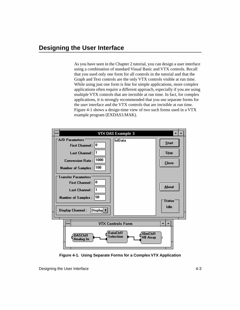
Designing the User Interface 4-3
Designing the User Interface
As you have seen in the Chapter 2 tutorial, you can design a user interface using a combination of standard Visual Basic and VTX controls. Recall that you used only one form for all controls in the tutorial and that the Graph and Text controls are the only VTX controls visible at run time. While using just one form is fine for simple applications, more complex applications often require a different approach, especially if you are using multiple VTX controls that are invisible at run time. In fact, for complex applications, it is strongly recommended that you use separate forms for the user interface and the VTX controls that are invisible at run time. Figure 4-1 shows a design-time view of two such forms used in a VTX example program (EXDAS3.MAK).
Figure 4-1. Using Separate Forms for a Complex VTX Application
4-4 Building Complex Applications
The user interface form (VTX DAS Example 3) in Figure 4-1 uses the Visual Basic frame control to create the following separate areas:
●
A/D Parameters frame - For setting parameters for the Analog In process of the DAS control (channels, conversion rate, and number of samples).
●
Transfer Parameters frame - For setting the parameters for the Selection process of DataCtrl1 and thereby specifying the number of data sets and data elements for the VB Array process to transfer.
●
Display Channel frame - For specifying the data set (channel) to be displayed in the list box.
●
Status frame - For displaying the status of the Analog In process in a label control.
In each frame, Visual Basic label controls are used to show the names of the parameters users of the application can set. Visual Basic text boxes are used to accept the user input.
In the center of the form is a Visual Basic list box to display the data selected in the Display Channel frame. On the right side of the form are the four command buttons that start the Analog In process (Start), stop all processes (Stop), exit the application (Close), and display an About dialog box for the application (About).
The VTX Controls form in Figure 4-1 uses the DAS, Data, and Transfer controls to perform the supporting tasks for the user interface:
●
DAS control - Performs an analog input operation, based on the channels, conversion rate, and number of samples specified by the user.
●
Data control - Selects the data for display, based on the channels and samples specified by the user.
●
Transfer control - Transfers the data specified by the user to a Visual Basic array for display in the list box.
As with a simple application, the next task after designing the forms for a complex application is setting the properties for the forms and controls.
Setting Properties 4-5
Setting Properties
In Chapter 2, you learned how to set properties for VTX controls at design time in the Properties and More Properties windows and how to set properties at run time using assignment statements. When you want to quickly set up and run a simple application that tests your hardware, you can set all the properties you need at design time in the Properties and More Properties windows of the VTX controls and then run the application. For more complex applications, you will need to set properties in code.
For the example shown in Figure 4-1 on page 4-3, properties such as Caption or Text and Name need to be set in the Properties window for the Visual Basic controls on the user interface form (VTX DAS Example 3). Similarly, properties for the VTX DAS, Data, and Transfer controls (VTX Controls Form) need to be set in the Properties window and in the More Properties window. To see the design-time property settings for this example, follow these steps:
1. Open the project VTX DAS Example 3 (EXDAS3.MAK) in Visual Basic by double-clicking the icon labelled DAS Example 3 in the Keithley VTX program group. If Visual Basic is already running, you can select Open Project from the File menu. From the Open Project dialog box, locate the VTX\EXAMPLES directory, choose EXDAS3.MAK from the list of files, and click OK.
2. After the project opens, double-click the form names, EXDAS3A.FRM and EXDAS3B.FRM to display the forms.
3. From each form, select a control, and press F4 to display the Properties window.
4. For the VTX controls, double-click the (More) property in the Properties window to display the More Properties window.
Recall from Chapter 3 that the availability of properties in the More Properties window depends on the settings of the ProcessSrc and Process properties in the Properties windows. This relationship is important for applications in which properties are set at run time (in code), such as VTX DAS Example 3. While you cannot change the Process or ProcessSrc properties in code, the choices you make at design time for these properties determine the availability and valid settings of other properties that you can change in code.
4-6 Building Complex Applications
In VTX DAS Example 3, users can specify the conversion rate and the number of samples per channel for the Analog In process. Therefore, while the ConvRate and Samples properties can be set at design time, these properties must be set in code. Depending on the process source selected for the DAS control, the valid settings for ConvRate and Samples change. The section “Accepting User Input,” on page 4-21 shows the code needed to set the ConvRate and Samples properties for this example.
Notes:
If you specify an invalid value for a property or an invalid property for a process source, process, mode, or control, the VTX software returns an error. Depending on the property, you may see the error message at design time or at run time.
By default, the VTX system displays dialog boxes when warnings or errors are detected at run time. These dialog boxes enable you to get help
with VTX warnings and errors while you are developing an application.
Connecting VTX Controls
In the tutorial in Chapter 2, you learned how to connect two VTX controls on the same form. Chapter 3 provided additional information about the types of connections and connection points for different VTX controls. For VTX DAS Example 3, connections are required from the DAS control to the Data control and from the Data control to the Transfer control. These connections were drawn using the same steps you learned in Chapter 2.
As you create more applications with VTX and Visual Basic, you may want to use multiple connections to or from VTX controls, specify the order in which the controls process the data on connections, draw interform connections, or delete connections. This section explains how to perform these operations.
Note:
You cannot connect to or from VTX controls that are in a Visual
Basic frame control.
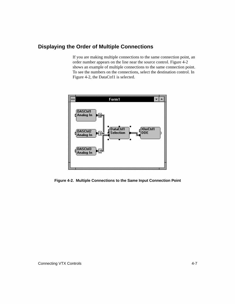
Connecting VTX Controls 4-7
Displaying the Order of Multiple Connections
If you are making multiple connections to the same connection point, an order number appears on the line near the source control. Figure 4-2 shows an example of multiple connections to the same connection point. To see the numbers on the connections, select the destination control. In Figure 4-2, the DataCtrl1 is selected.
Figure 4-2. Multiple Connections to the Same Input Connection Point
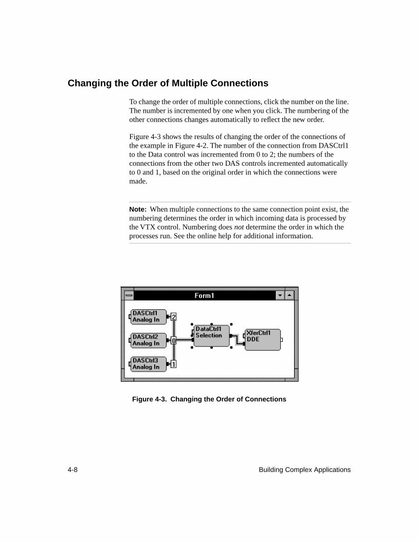
4-8 Building Complex Applications
Changing the Order of Multiple Connections
To change the order of multiple connections, click the number on the line. The number is incremented by one when you click. The numbering of the other connections changes automatically to reflect the new order.
Figure 4-3 shows the results of changing the order of the connections of the example in Figure 4-2. The number of the connection from DASCtrl1 to the Data control was incremented from 0 to 2; the numbers of the connections from the other two DAS controls incremented automatically to 0 and 1, based on the original order in which the connections were made.
Note:
When multiple connections to the same connection point exist, the numbering determines the order in which incoming data is processed by the VTX control. Numbering does
not
determine the order in which the
processes run. See the online help for additional information.
Figure 4-3. Changing the Order of Connections
Connecting VTX Controls 4-9
Drawing Interform Connections
To connect two VTX controls that reside on different forms, perform the following steps:
1. Display both forms.
2. With the cursor on the output connection point of the source VTX control, press and hold down the left mouse button.
3. Drag the cursor across the forms to the input connection point of the destination VTX control. Note that the cursor changes as you drag it.
4. When you reach the input connection point and the cursor changes, release the left mouse button.
When you release the mouse button, the connection is represented on the form of the source control by a line from the output connection point to a box containing a letter. The letter associated with an interform connection indicates the order in which the connection was made. On the form of the destination control, the connection is represented by a line from another box with the same letter to the input connection point.
The placement of the VTX controls on the two forms determines how the connections appear. You cannot re-route an interform connection; instead, you must delete and then recreate it.
Note:
Before deleting interform connections, ensure that you have the forms containing the source and destination controls displayed.
Otherwise, the deletion and subsequent additions may not work properly.
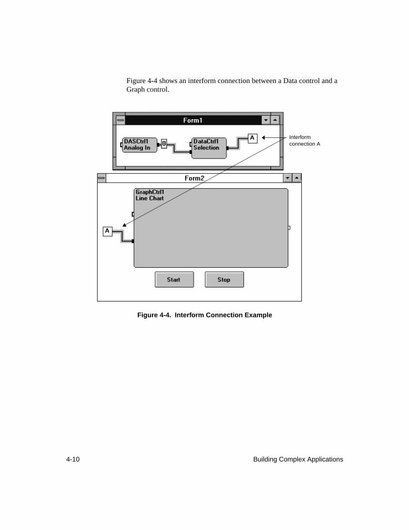
4-10 Building Complex Applications
Figure 4-4 shows an interform connection between a Data control and a Graph control.
Figure 4-4. Interform Connection Example
Interform connection A
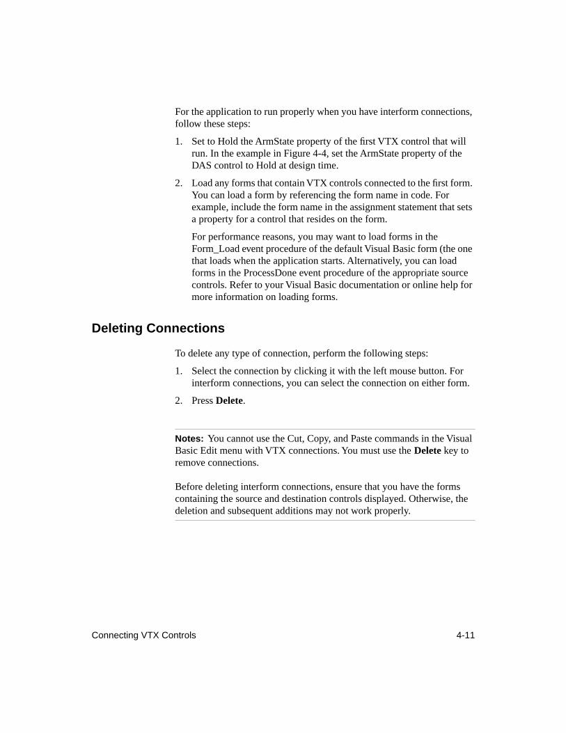
Connecting VTX Controls 4-11
For the application to run properly when you have interform connections, follow these steps:
1. Set to Hold the ArmState property of the first VTX control that will run. In the example in Figure 4-4, set the ArmState property of the DAS control to Hold at design time.
2. Load any forms that contain VTX controls connected to the first form. You can load a form by referencing the form name in code. For example, include the form name in the assignment statement that sets a property for a control that resides on the form.
For performance reasons, you may want to load forms in the Form_Load event procedure of the default Visual Basic form (the one that loads when the application starts. Alternatively, you can load forms in the ProcessDone event procedure of the appropriate source controls. Refer to your Visual Basic documentation or online help for more information on loading forms.
Deleting Connections
To delete any type of connection, perform the following steps:
1. Select the connection by clicking it with the left mouse button. For interform connections, you can select the connection on either form.
2. Press
Delete
.
Notes:
You cannot use the Cut, Copy, and Paste commands in the Visual Basic Edit menu with VTX connections. You must use the
Delete
key to remove connections.
Before deleting interform connections, ensure that you have the forms containing the source and destination controls displayed. Otherwise, the
deletion and subsequent additions may not work properly.
4-12 Building Complex Applications
Because you can easily select both a VTX control and its connections, ensure that only the connection you want to delete is highlighted. For example, in Figure 4-5, the Data control and the three connections to the control are selected. To delete only one of the connections to the Data control, you would deselect the Data control and click only the connection you want to delete.
Figure 4-5. Selecting Connections for Deletion
Writing Code
You can create simple VTX applications without writing any code. Connections between VTX controls enable you to read analog input data and display it without a single line of code. However, complex applications that let users specify the parameters for an operation and decide when to run the operation do require some code. The code integrates the Visual Basic components of the user interface with the supporting tasks performed by the VTX controls. For example, when a user specifies the number of samples to read in a Visual Basic text box, an assignment statement passes the information to the VTX DAS control. Write any code needed for your application after setting the properties and connecting the VTX controls.
Writing Code 4-13
The VTX system provides events and functions that you can use to build complex applications. This section briefly describes these features of the VTX system. See the online help for details on events and functions.
To integrate the VTX components of a user interface (Text or Graph control) with tasks performed by other VTX controls, all you need are connections between the appropriate VTX controls. To integrate the Visual Basic components of the user interface with the tasks performed by VTX controls, you can use the event procedures of certain Visual Basic controls on the user interface to set parameters for and start tasks performed by VTX controls.
In the tutorial in Chapter 2, you used the Click event procedures of three Visual Basic command buttons to start the VTX DAS control, prevent the VTX controls from starting again, and gracefully exit the application. This section provides additional examples for integrating the user interface with tasks performed by VTX controls (including use of VTX connections and code from VTX DAS Example 3). The examples show you how to
●
Accept user input for the parameters of operations performed by VTX controls.
●
Start and stop operations.
●
Display status information.
●
Display data.
VTX Events
All VTX controls provide two events that you can use as appropriate to your application. The events are ProcessDone and ProcessError. You cannot disable these events.
The CTM control provides an additional event that notifies you of the completion of a counter/timer operation, ProcessCTMDone. You cannot enable or disable this event. You may want to use the event procedure to take action based on which CTM operation completed.
The DAS control provides an additional event that notifies you of the status of an Analog In process: the NDataDone event. You can enable and disable the NDataDone event with a property (NData). Refer to the VTX online help for details.
4-14 Building Complex Applications
The Text control uses several standard Visual Basic events in addition to ProcessDone and ProcessError. Refer to the Visual Basic
Language Reference
or online help for details on using these events.
Every event has an associated event procedure that you can use, depending on the needs of your application. The rest of this section describes the VTX events and ways in which you may want to use them and provides a brief introduction to the standard Visual Basic events used by the VTX Text control.
ProcessDone Event
The ProcessDone event indicates that a VTX control completed its configured process. This event can also indicate the occurrence of a minor problem (one that did not prevent the completion of the process). If a minor problem occurs, the control generates a warning message.
The ProcessDone event returns either zero or non-zero values, as follows:
●
0
- Indicates that the VTX process completed without a warning.
●
Integer > 0
- Indicates that the control encountered a problem but was still able to complete the process. The number is the code for the warning message.
Note that even if the ProcessDone event returns a warning message code, the application continues to run.
The VTX online help provides brief descriptions of all warnings generated by VTX controls. Note that some warnings are common to all VTX controls while others are specific to individual VTX controls. If you cannot find a warning in the control-specific listing, check the listing in the topic "Warnings and Errors Returned by All VTX Controls."
In the ProcessDone event procedure, you can test the value returned and then perform additional tasks as appropriate to your application. For example, when a process completes without a warning, you may want to start the next VTX control by setting its ArmState property to 0 (Wait For Control Connection) or 1 (Ignore Control Connection). If you are using ProcessDone event procedures to control when VTX controls start, ensure that, for each VTX control that is started in a ProcessDone event procedure, you first set the ArmState property to Hold in the Properties window or in code, as appropriate to your application.
Writing Code 4-15
ProcessError Event
The ProcessError event indicates that an error condition within the VTX control caused that control to stop before completing its configured process. This event automatically sets the ArmState property of the stopped VTX control to the value Hold so that the control cannot run again. Controls connected to the stopped control cannot run. However, processes that are running independently of the stopped control continue to run. Only the VTX control that generated the event stops running.
The ProcessError event occurs only if an error occurs. This event returns a non-zero integer, which is the code for the error. In the ProcessError event procedure, you can test the value and then, based on the value, take action appropriate to your application. For example, you may want to clear the control and data connections to affected VTX controls with the ClearInputs property. See the online help for the ClearInputs property for details.
The VTX online help provides brief descriptions of all errors generated by VTX controls. Note that some errors are common to all VTX controls while others are specific to individual VTX controls. If you cannot find an error in the control-specific listing, check the listing in the topic, "Warnings and Errors Returned by All VTX Controls."
For information on writing code to handle errors, see the section “Error Handling,” on page 4-36, or the topic, "Writing Code to Handle Errors," in the online help.
ProcessCTMDone Event
The CTM control lets you synchronize multiple counter/timer operations by letting you start up to five counter/timer operations at once. While the ProcessDone event notifies you that all counter/timer operations are complete, the ProcessCTMDone event notifies you when each counter/timer operation completes. The event returns an integer that corresponds to the number of the counter/timer operation that completed.
You cannot enable or disable this event. You may want to use this event to take action based on which operation completed. For example, if the EventCount operation completes, you may want to display the current count. To display the current count, you can use the VTX Text control or a Visual Basic label or text box control.
4-16 Building Complex Applications
NDataDone Event
The NDataDone event of the DAS control indicates that the control has read the samples specified with the NData property. Setting NData to 0 disables the event. Setting NData to any other value enables the event and specifies the number of samples read that generate the event.
The NDataDone event also notifies you that the samples specified with NData have been sent out to the next VTX control in the application. You might want to use the NData property and NDataDone event to send out subsets of acquired samples for preliminary viewing in a graph or spreadsheet. You can do this without writing any code.
See the online help for the DAS control, in particular the topics, "NDataDone Event" and "NData Property," for more information.
Text Control Events
The Text control uses a set of standard Visual Basic events that occur as appropriate at run time. Note that these events can occur when the Text control is not running because editing is typically done before the Text control starts or after the Text control runs. Refer to the Visual Basic online help or the Visual Basic
Language Reference
for details on these events.
You do not need to write any code to accept or reject run-time edits. While the Text control does not reject invalid key presses, the result removes them because the Text control does check for valid formatting. For example, suppose the specified format is General Number and the user of the application enters 12XP and then clicks the Send button of the Text control toolbar. The Text control checks the entry against the specified format and, before sending out the data, changes it to 12. After the data is sent, the display shows 12 instead of 12XP.
Most of the Visual Basic events are common to both Text control processes.
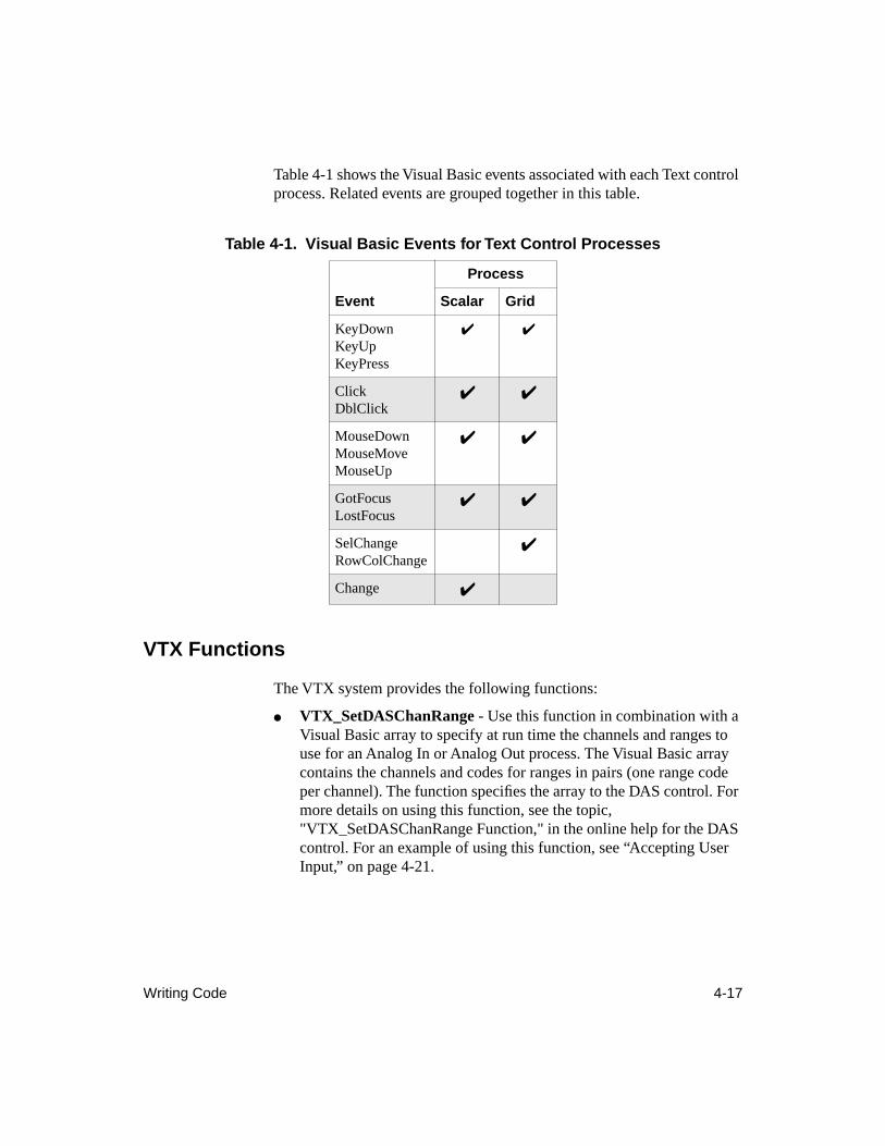
Writing Code 4-17
Table 4-1 shows the Visual Basic events associated with each Text control process. Related events are grouped together in this table.
VTX Functions
The VTX system provides the following functions:
●
VTX_SetDASChanRange
- Use this function in combination with a Visual Basic array to specify at run time the channels and ranges to use for an Analog In or Analog Out process. The Visual Basic array contains the channels and codes for ranges in pairs (one range code per channel). The function specifies the array to the DAS control. For more details on using this function, see the topic, "VTX_SetDASChanRange Function," in the online help for the DAS control. For an example of using this function, see “Accepting User Input,” on page 4-21.
Table 4-1. Visual Basic Events for Text Control Processes
Process
Event Scalar Grid
KeyDownKeyUpKeyPress
✔ ✔
ClickDblClick
✔ ✔
MouseDownMouseMoveMouseUp
✔ ✔
GotFocusLostFocus
✔ ✔
SelChangeRowColChange
✔
Change
✔
4-18 Building Complex Applications
●
VTX_GetDASChanRange
- Use this function to read at run time the channels (and ranges) currently specified for an Analog In or Analog Out process. You can read the settings selected at design time in the Channel/Range dialog box or the settings made at run time with the VTX_SetDASChanRange function and a Visual Basic array. For details on using this function, see the topic, "VTX_GetDASChanRange Function," in the online help for the DAS control.
●
VTX_SetXferVBArray
- To move data between the VTX environment and a Visual Basic array, use the VB Array process of the Transfer control. When using this process, you use the VTX_SetXferVBArray function to specify your array to the Transfer control. See the online help for the Transfer control for details on using this function.
Note that you must declare these functions and their associated Visual Basic arrays in the appropriate global module of your application. The example programs provided with VTX software include a global module called VTXDECL.BAS, which defines the Option Base (0) and declares the VTX functions and a few global constants that you may want to use with the ArmState property. You can copy what you require from VTXDECL.BAS into your global module or from the online help.
The VTX_SetDASChanRange and VTX_SetXferVBArray functions return the value zero when no error is encountered. If an error occurs, these functions return a non-zero value that is the code for the error. See the online help for assistance with errors returned by these functions.
Because the VTX functions can return error codes, it is strongly recommended that you check the return value of each function in code to ensure that the function was successful. VTX DAS Example 3 uses the following code in the Click event procedure of the Start command button check the return values of the VTX_SetDASChanRange and VTX_SetXferVBArray functions:
'Declare a variable for the return values of the Transfer and DAS'control functions Dim ReturnCode%
'Download the ChanRangeArray into the DAS Control'Note: ReturnCode% will contain 0 if the function is successful.
ReturnCode% = VTX_SetDASChanRange(frmControls.DASCtrl1.hCtl, ChanRangeArray())
Writing Code 4-19
'Check that the function was successful.'Display message if the function returns an error.
If ReturnCode% <> 0 ThenMsgBox "The Channel/Range data could not be set.", 48, "VTX Error"EndEnd If
'Set DataBuffer as the array to receive data from the Transfer control'Note : ReturnCode% will contain 0 if the function is successful.
ReturnCode% = VTX_SetXferVBArray(frmControls.XferCtrl1.Hctl, DataBuffer())
'Check that the function was successful.'Display message if the function returns an error.
If ReturnCode% <> 0 ThenMsgBox "An array could not be passed to the Xfer control.", 48, "VTX Error"EndEnd If
Integration of the User Interface and Supporting Tasks
To integrate the VTX components of a user interface (Text or Graph control) with tasks performed by other VTX controls, all you need are connections between the appropriate VTX controls. To integrate the Visual Basic components of the user interface with the tasks performed by VTX controls, you can use code in the event procedures of certain Visual Basic controls. In VTX DAS Example 3, assignment statements in the Click event procedure of the command button captioned Start set the ConvRate and Samples properties of the DAS control based on user input in corresponding Visual Basic text box controls.
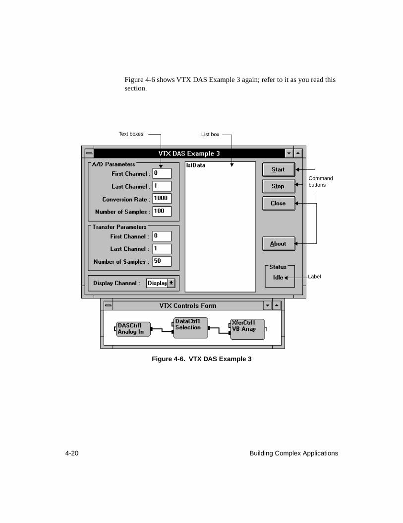
4-20 Building Complex Applications
Figure 4-6 shows VTX DAS Example 3 again; refer to it as you read this section.
Figure 4-6. VTX DAS Example 3
Command buttons
Label
List boxText boxes
Writing Code 4-21
Accepting User Input
VTX DAS Example 3 accepts user input for the parameters of the Analog In process of DASCtrl1 and the Selection process of DataCtrl1. To let users set these parameters, this application uses Visual Basic text boxes. You can also use the standard Visual Basic list boxes, combo boxes, and radio buttons to present users with a fixed list of settings.
To pass the user input to the VTX controls shown in Figure 4-6, you can use either the appropriate event procedure for the Visual Basic control or the Click event procedure for the Start command button. The example in Figure 4-6 lets users specify the following parameters for the Analog In process:
●
First and last channels (group of consecutive channels)
●
Conversion rate
●
Total number of samples to acquire
The following assignment statements in the Click event procedure of the Start command button of this application accept user input when VTX DAS Example 3 runs. Note that this code must use the name of the form on which the VTX controls reside, namely
frmControls
.
frmControls.DASCtrl1.Samples = CLng(txtNumberSamples.Text)frmControls.DASCtrl1.ConvRate = CLng(txtConvRate.Text)
The following code takes the first and last channels specified in the text boxes and uses the VTX_SetDASChanRange function to specify the channels and the same range for each channel to the DAS control:
'Calculate the ChanRangeArray Dim NumChans%, Channel%, Count% NumChans% = CLng(txtlastChan.Text) - CLng(txtFirstChan.Text) + 1 ReDim ChanRangeArray(NumChans% * 2) As Integer ChanRangeArray(0) = NumChans% 'Number of channel-range pairs Channel% = CLng(txtFirstChan.Text) For Count% = 1 To 2 * NumChans% - 1 Step 2 ChanRangeArray(Count%) = Channel% 'Channel number ChanRangeArray(Count% + 1) = 1 'Code for range Channel% = Channel% + 1 Next Count%'Specify the ChanRangeArray to the DAS Controlx = VTX_SetDASChanRange (frmControls.DASCtrl1.hCtl, ChanRangeArray())
4-22 Building Complex Applications
The user of the application can set the following parameters for the Selection process:
●
First and last channels
●
Number of samples to extract (and transfer to a Visual Basic array using the Transfer control)
The following code takes the user input for the channels and samples to extract for the Transfer and sets the appropriate properties of the VTX Data control. Note that the text boxes for the channels are called txtFirstSet and txtLastSet. The text box for samples is called txtSetLength. In the VTX environment, channels map to data sets and samples to data elements.
'Set up the VTX Data control to select data Dim NumPoints, NumSets As Long NumSets = 1 + CLng(txtLastSet.Text) - CLng(txtFirstSet.Text) NumPoints = CLng(txtSetLength.Text) frmControls.DataCtrl1.FirstDataSet = CLng(txtFirstSet.Text) frmControls.DataCtrl1.NumDataSets = NumSets frmControls.DataCtrl1.NumElements = NumPoints
This code is in the Click event procedure for the Start command button. However, it can also be in the ProcessDone event procedure for the DAS control. In that case, you must follow these steps:
1. In the More Properties window, in the Click event procedure for the Start command button, or in the ProcessDone event procedure for the DAS control, set the ArmState property for the Data control to Hold.
2. In the ProcessDone event procedure for the DAS control, set up the Data control properties as shown in the preceding code example.
3. In the ProcessDone event procedure for the DAS control, set the ArmState property to Wait for Control Connection or Ignore Control Connection to start the Data control.
Writing Code 4-23
The resulting ProcessDone event procedure for the DAS control follows. Note that this example sets the ArmState property of the Data control to Hold before setting up the Selection process and then sets the property to Ignore Control Connection after the Selection process properties have been set. Constants defined in the global module are used to set the ArmState property (
HOLD and IGNORE_CONNECT).
Sub DASCtrl1.ProcessDone ()
’Put the Data control on Hold while setting its properties DataCtrl1.ArmState = HOLD
'Set up the VTX Data control to select data Dim NumPoints, NumSets As Long NumSets = 1 + CLng(txtLastSet.Text) - CLng(txtFirstSet.Text) NumPoints = CLng(txtSetLength.Text) DataCtrl1.FirstDataSet = CLng(txtFirstSet.Text) DataCtrl1.NumDataSets = NumSets DataCtrl1.NumElements = NumPoints
'Start the Data control DataCtrl1.ArmState = IGNORE_CONNECT
The Transfer control starts as soon as it receives data and control from the Data control in this application.
The following code sets the dimensions of the Visual Basic array to which the Transfer control transfers the analog input data to match the number of samples (data elements) and the number of channels (data sets) that the user has specified for the transfer:
'Reshape the Visual Basic array called DataBuffer to the required size ReDim DataBuffer(NumPoints - 1, NumSets - 1) As Integer
'Set the array called DataBuffer as the target of the Transfer Controlx = VTX_SetXferVBArray (frmControls.XferCtrl1.hCtl, DataBuffer())
The format of the Visual Basic array must be (number of data elements, number of data sets). The dimensions of the array receiving the data must match the dimensions of the data being transferred exactly. Otherwise, the Transfer control returns an error at run time.
4-24 Building Complex Applications
Starting/Stopping Operations
For a VTX control to start, the following conditions must be met:
● The ArmState property of the control must be set to Wait For Control Connection (0, the default) or Ignore Control Connection (1). This property can be set at design time or at run time.
Note that when you set ArmState to Ignore Control Connection, the control runs once when all data is available and then sets the property to Wait For Control Connection. See the ArmState property description in the online help for additional information.
● The conditions of all data input connections must be met before a control can start.
For example, a Computation control has two data input connections, one from a Statistics control and the other from a Data control. The Statistics and Data controls must have completed their processes and passed the data to the Computation control before the Computation control can start its configured process.
The VTX Transfer control has an additional rule: If the configured process is the VB Array process, then the control cannot start until you have specified the Visual Basic array to the control (using the VTX_SetXferVBArray function).
VTX DAS Example 3 uses two command buttons to start and stop operations, labelled Start and Stop. As with the application in Chapter 2, the Caption property of the command button that starts the operation is set to Start and its Name property is set to cmdStart. Similarly for the command button that stops the operation, the Caption property is set to Stop and the Name property to cmdStop. To enable the command buttons to start and stop the operation, code has been added to the Click event procedures for the buttons.
Writing Code 4-25
Click Event Procedure - Starting VTX Controls
To enable the command button to start the operations set up with the VTX controls in VTX DAS Example 3, the following assignment statement is added to the Click event procedure for the Start command button:
frmControls.DASCtrl1.ArmState = IGNORE_CONNECT
where IGNORE_CONNECT is a global constant that represents the ArmState property setting, Ignore Control Connection. This constant is one of several defined in the global module that is included with the VTX example programs (VTXDECL.BAS); you might want to copy the constant definitions to make your code more readable.
The Ignore Control Connection setting for the ArmState property causes the control to start when all data is available. After the control runs once, the control automatically sets ArmState to Wait For Control Connection. The Wait For Control Connection setting means that the control cannot start again until its control and data input connections are met or until a line of code sets the ArmState property for this control to Ignore Control Connection. See the online help for details on using the ArmState property.
Click Event Procedure - Stopping VTX Controls
To enable a command button to stop an operation or prevent an operation from running again, use one of the following options:
● Visual Basic End Statement - Useful when debugging, this statement stops everything.
● VTX ArmState Property - Useful when you have controls in a loopback, set this property to Hold when you want to prevent a control from starting again.
● VTX Halt Property - To stop VTX controls and ensure that they cannot start again until other code is executed, use the following assignment statement for each VTX control in the Click event procedure for a command button:
x = VTXform . VTXcontrol .Halt 'stop the control
where x is a variable that you want to use to store the status of the control before the control is stopped. The Halt property also sets the ArmState property of the control to Hold so that it cannot start again
4-26 Building Complex Applications
until code changes the property setting to 0 - Wait For Control Connection or 1 - Ignore Control Connection. You must use the Halt property to stop a continuously running DAS process or a continuously running CTM operation. See the online help for these controls for details.
VTX DAS Example 3 uses the following code in the Click event procedure of the Stop command button to stop the DAS control and display a message concerning the status of the control prior to the halt:
Sub cmdStop_Click () 'Halt the DAS Control Dim Status%, State$, Message$ 'Halt the DAS control and record its prior status Status% = frmControls.DASCtrl1.Halt If Status% = RUNNING Then State$ = "running" Else State$ = "not running" End If Message$ = "The DAS control was " & State & ". A halt has been issued." MsgBox Message$, 64, "DAS Example 3"End Sub
How VTX controls are started, stopped, and prevented from starting again is very specific to each application. Coordinate the properties that govern these actions carefully to ensure that controls run only when you intend them to run. For additional information, see the online help.
Writing Code 4-27
Displaying Status
All VTX controls generate one of two events that inform you of the status of the control: ProcessDone or ProcessError. These events return values that you can test. After testing a value in the associated event procedure, you may want to display an appropriate message in a Visual Basic text box in the user interface of the application. For example, the application shown in Figure 4-6 on page 4-20 updates the label in the Status frame in the ProcessDone event procedure for Transfer control, as follows:
frmMain.lblStatus.Caption = "Idle"
where frmMain is the name of the form on which the label control resides (the VTX controls are on a separate form). For more information on events, see “VTX Events,” on page 4-13 and the online help.
To check the status of a VTX control outside of the events, you can use the Status property. For example, the following If statement tests the value of Status:
If (DASCtrl1.Status) AND 1 = 0 Then ...
For more information on the Status property, see the online help.
In addition to the common Status property, the CTM control provides the OpStatus property, which lets you check the status of any one of the five possible counter/timer operations. Refer to the online help for the CTM control for details on the OpStatus property.
Displaying Data
To display data, the VTX system provides the following controls:
● Text control - The Text control lets you create, display, and modify data within the VTX environment, without requiring code. Use the Scalar process when the data to be displayed consists of a single data set with a single data element. The Scalar process produces a text-box-like display. Use the Grid process when data consists of a single data set with multiple data elements or multiple data sets with one or more data elements.
● Graph control - The Graph control also lets you display data within the VTX environment, without requiring code. Use the appropriate

4-28 Building Complex Applications
process to display data in a line or scatter chart (Line Chart process), strip chart (Strip Chart process), or bar chart (Bar Chart process).
● Transfer control - The Transfer control lets you move data out of the VTX environment for use with other Windows or Visual Basic applications. Use the VBArray process to move data to a Visual Basic array for use with another Visual Basic custom control. This process requires additional code. To move data to a disk file, use the Disk process. To move data to a Windows spreadsheet application, use the DDE process. Neither the Disk nor DDE process require code. VTX DAS Example 3 uses the Transfer control to move data to a Visual Basic array for display in the list box on the user interface.
The supported spreadsheet applications are Microsoft Excel, Lotus 1-2-3, and Quattro Pro. See the README file for details on the versions of these applications that are supported by the VTX software.
Displaying a Scalar
Using the tutorial in Chapter 2, you created an application that displays a sample read during a single-point digital input operation. Figure 4-7 shows the design-time view of this example again.
Figure 4-7. Displaying a Single Data Point - Design-Time View
Text control, Scalar process
Visual Basic command button controls
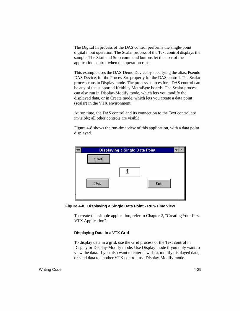
Writing Code 4-29
The Digital In process of the DAS control performs the single-point digital input operation. The Scalar process of the Text control displays the sample. The Start and Stop command buttons let the user of the application control when the operation runs.
This example uses the DAS-Demo Device by specifying the alias, Pseudo DAS Device, for the ProcessSrc property for the DAS control. The Scalar process runs in Display mode. The process sources for a DAS control can be any of the supported Keithley MetraByte boards. The Scalar process can also run in Display-Modify mode, which lets you modify the displayed data, or in Create mode, which lets you create a data point (scalar) in the VTX environment.
At run time, the DAS control and its connection to the Text control are invisible; all other controls are visible.
Figure 4-8 shows the run-time view of this application, with a data point displayed.
Figure 4-8. Displaying a Single Data Point - Run-Time View
To create this simple application, refer to Chapter 2, "Creating Your First VTX Application".
Displaying Data in a VTX Grid
To display data in a grid, use the Grid process of the Text control in Display or Display-Modify mode. Use Display mode if you only want to view the data. If you also want to enter new data, modify displayed data, or send data to another VTX control, use Display-Modify mode.
1
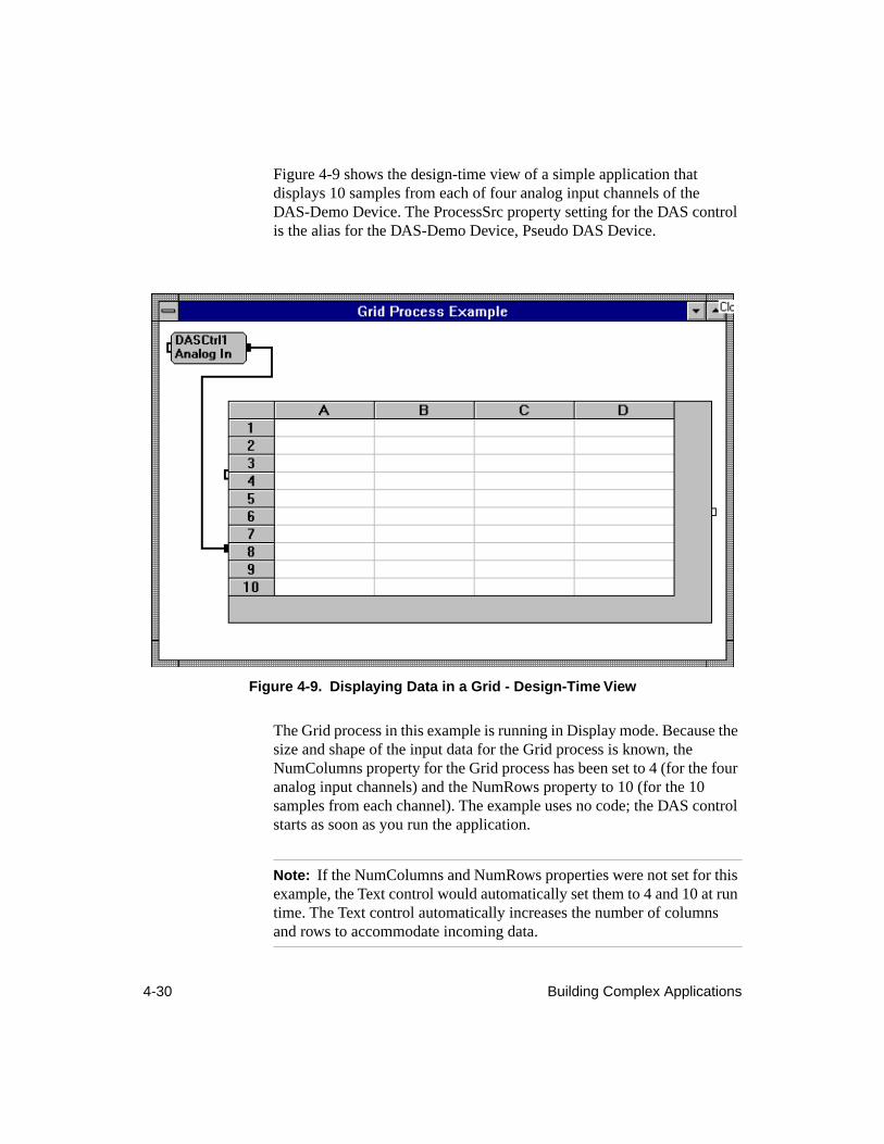
4-30 Building Complex Applications
Figure 4-9 shows the design-time view of a simple application that displays 10 samples from each of four analog input channels of the DAS-Demo Device. The ProcessSrc property setting for the DAS control is the alias for the DAS-Demo Device, Pseudo DAS Device.
Figure 4-9. Displaying Data in a Grid - Design-Time View
The Grid process in this example is running in Display mode. Because the size and shape of the input data for the Grid process is known, the NumColumns property for the Grid process has been set to 4 (for the four analog input channels) and the NumRows property to 10 (for the 10 samples from each channel). The example uses no code; the DAS control starts as soon as you run the application.
Note: If the NumColumns and NumRows properties were not set for this example, the Text control would automatically set them to 4 and 10 at run time. The Text control automatically increases the number of columns and rows to accommodate incoming data.
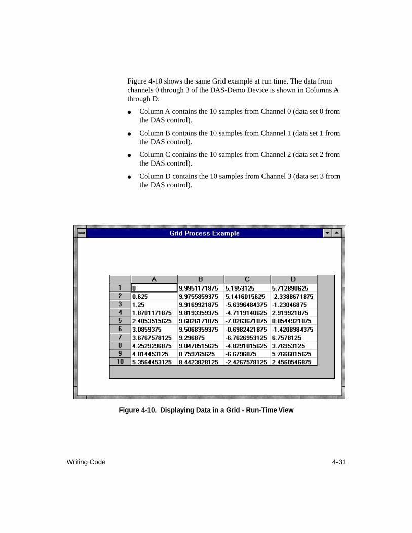
Writing Code 4-31
Figure 4-10 shows the same Grid example at run time. The data from channels 0 through 3 of the DAS-Demo Device is shown in Columns A through D:
● Column A contains the 10 samples from Channel 0 (data set 0 from the DAS control).
● Column B contains the 10 samples from Channel 1 (data set 1 from the DAS control).
● Column C contains the 10 samples from Channel 2 (data set 2 from the DAS control).
● Column D contains the 10 samples from Channel 3 (data set 3 from the DAS control).
Figure 4-10. Displaying Data in a Grid - Run-Time View
4-32 Building Complex Applications
Note that because the data is shown using the Double data type, the cell width for all cells in this grid has been adjusted to 3500. The units for the cell width are 1/256th of the size of the letter O in the selected font. To change the width for all cells in the grid, perform the following steps:
1. Select the Text control and click the ellipsis as indicated for the (More) property to display the More Properties window.
2. In the More Properties window, ensure that the DataSetIndex property is set to -1 (all data sets or columns).
3. Click the CellWidth property.
4. In the Settings Box at the top of the More Properties window, enter the new width.
To change the cell width or any other attribute of a particular column, perform the following steps in the More Properties window:
1. Set the DataSetIndex property to the index of the column you want to change. For example, to change the attributes of the column with the default heading A, change the DataSetIndex property to 0.
2. Click the property you want to change. For example, to change the heading for the column with the default heading A, click the DataSetLabel property.
3. In the Settings Box at the top of the More Properties window, enter the text that you want to appear as the column heading. For example, you might change column A in the example program to read "Channel 0".
4. Repeat steps 2 and 3 for each property that you want to change for the specified data set or column. The following properties let you specify the attributes of a data set or column: CellWidth, DataSetLabel, Format, HAlignment, and VAlignment.
See the topic, "Setting Up Grid Processes," in the online help of the Text control for a detailed procedure for setting the properties for a Grid process.
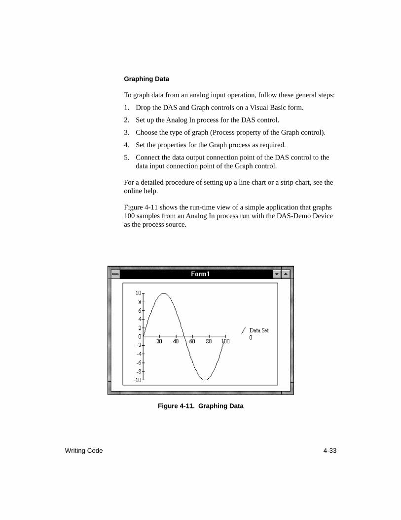
Writing Code 4-33
Graphing Data
To graph data from an analog input operation, follow these general steps:
1. Drop the DAS and Graph controls on a Visual Basic form.
2. Set up the Analog In process for the DAS control.
3. Choose the type of graph (Process property of the Graph control).
4. Set the properties for the Graph process as required.
5. Connect the data output connection point of the DAS control to the data input connection point of the Graph control.
For a detailed procedure of setting up a line chart or a strip chart, see the online help.
Figure 4-11 shows the run-time view of a simple application that graphs 100 samples from an Analog In process run with the DAS-Demo Device as the process source.
Figure 4-11. Graphing Data
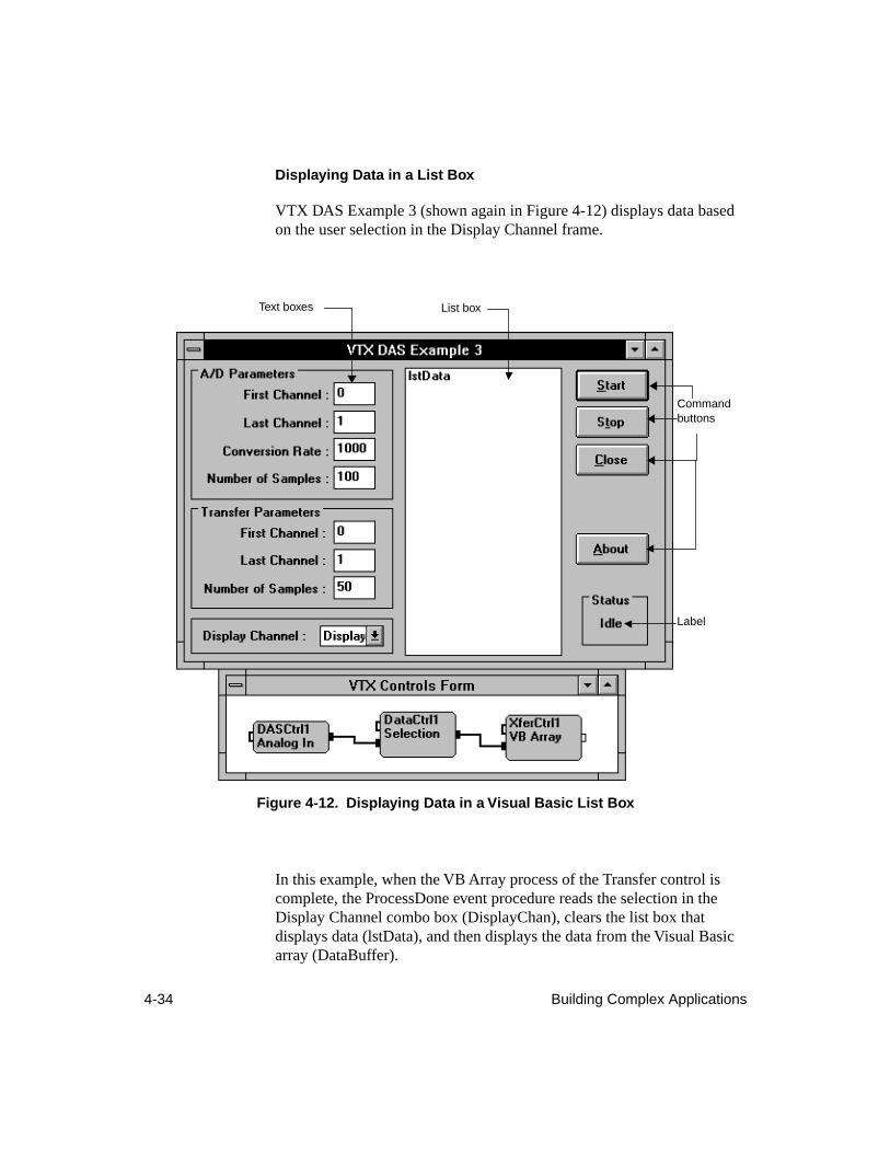
4-34 Building Complex Applications
Displaying Data in a List Box
VTX DAS Example 3 (shown again in Figure 4-12) displays data based on the user selection in the Display Channel frame.
Figure 4-12. Displaying Data in a Visual Basic List Box
In this example, when the VB Array process of the Transfer control is complete, the ProcessDone event procedure reads the selection in the Display Channel combo box (DisplayChan), clears the list box that displays data (lstData), and then displays the data from the Visual Basic array (DataBuffer).
Command buttons
Label
List boxText boxes
Writing Code 4-35
The ProcessDone event procedure is written as follows:
Sub XferCtrl1_ProcessDone (WarningCode As Integer)
Dim Count%, msg$, ChanNumber%
'Get the required channel to be displayedChanNumber% = frmMain.DisplayChan.ListIndex
'Clear the data list
frmMain.lstData.Clear
'Display the requested data from the Visual Basic 'array called DataBufferFor Count% = 0 To UBound(DataBuffer, 1)
msg$ = Str$(Count%) + Chr$(9)msg$ = msg$ + Str$(DataBuffer(Count%, ChanNumber%))
frmMain.lstData.AddItem msg$, Count%Next Count%
End Sub
Displaying Data in a Windows Spreadsheet
To display data from an Analog In process in a Windows spreadsheet, follow these general steps:
1. Drop the DAS and Transfer controls on a form.
2. Set up the Analog In process for the DAS control.
3. Set the Process property of the Transfer control to DDE to send the data to a spreadsheet file.
4. Click the ellipsis as indicated for the (More) property to display the More Properties window.
5. In the More Properties window, select Out From VTX for the Direction property.
6. Use the other DDE process properties to specify the spreadsheet application, spreadsheet file, and starting location in the spreadsheet for the data. For details on these properties, see the online help.
7. Connect the data output connection point of the DAS control to the data input connection point of the Transfer control.
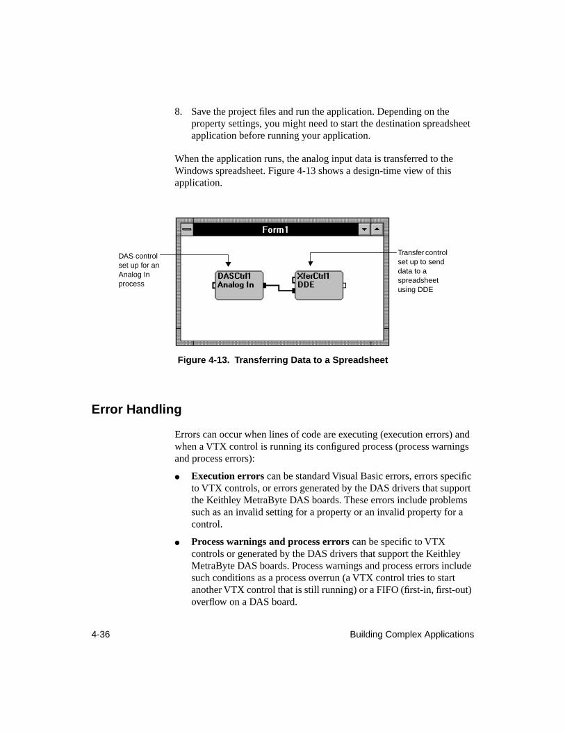
4-36 Building Complex Applications
8. Save the project files and run the application. Depending on the property settings, you might need to start the destination spreadsheet application before running your application.
When the application runs, the analog input data is transferred to the Windows spreadsheet. Figure 4-13 shows a design-time view of this application.
Figure 4-13. Transferring Data to a Spreadsheet
Error Handling
Errors can occur when lines of code are executing (execution errors) and when a VTX control is running its configured process (process warnings and process errors):
● Execution errors can be standard Visual Basic errors, errors specific to VTX controls, or errors generated by the DAS drivers that support the Keithley MetraByte DAS boards. These errors include problems such as an invalid setting for a property or an invalid property for a control.
● Process warnings and process errors can be specific to VTX controls or generated by the DAS drivers that support the Keithley MetraByte DAS boards. Process warnings and process errors include such conditions as a process overrun (a VTX control tries to start another VTX control that is still running) or a FIFO (first-in, first-out) overflow on a DAS board.
Transfer control set up to send data to a spreadsheet using DDE
DAS control set up for an Analog In process
Writing Code 4-37
Note that you can avoid process overruns by using the ClearInputs property in conjunction with the ArmState property in the ProcessDone event procedures for VTX controls or in Click event procedures for command buttons that start or stop operations. See the online help for the ClearInputs property for more information.
Execution Errors
Execution errors can occur when you try to run a Visual Basic application and a line of code contains an error. Visual Basic, the VTX system, or the DAS driver may discover these errors.
By default, execution errors detected by the VTX system or the DAS driver produce a VTX dialog box that displays the name of the VTX control that generated the error as well as the error number and message. The dialog box also contains the following buttons:
● Help - Provides access to a related topic in the VTX online help system. The dialog box remains open while you access the VTX help system.
● OK - Exits the dialog box.
When you exit the VTX dialog box, the standard Visual Basic error handler resumes control. Standard Visual Basic error handling means that if it exists (invoked by the OnError statement), the error handling subroutine will run. If the error handling subroutine does not exist, Visual Basic presents its error message dialog box and stops the application.
Note: If Visual Basic detected the error, the VTX dialog box cannot appear because the standard Visual Basic error handler retains control.
If you want to disable the error dialog box and access to help, use the VTX Options window of the VTX Configuration utility. When you disable the Help On Errors option, the VTX dialog box does not appear and the standard Visual Basic error handler retains control. See the section, “Enabling and Disabling VTX Options,” on page 4-41 for more information on the VTX Options window.
4-38 Building Complex Applications
In each code module in which you set properties for the VTX controls, it is strongly recommended that you add code to handle error messages that may be returned. Otherwise, any execution error that occurs causes Visual Basic to generate an error message and stop the program. See the Visual Basic online help for assistance in using the OnError and Resume statements and the Err, Erl, Error, and Error$ functions to write error handling subroutines.
Process Warnings and Errors
Process warnings and process errors can occur only after a VTX control starts running its configured process. The VTX control or a DAS driver may detect process warnings and errors. Note that the VTX controls communicate these errors through events. Therefore, instead of using the OnError subroutine to handle these errors, you must use the associated event procedures.
Process warnings and errors provide the following information:
● Process Warnings - Indicate that a minor problem occurred while the process was running. Warnings do not stop a VTX control from completing its configured process. The control communicates the condition to you through the warning number value returned by the ProcessDone event.
● Process Errors - Indicate that the control stopped before completing its configured process because of a particular condition. The control communicates the condition to you through the error code value returned by the ProcessError event.
By default, the dialog boxes for the process warnings and errors are enabled so that you can quickly get help with process errors. These dialog boxes display the name of the VTX control that generated the warning or error, text describing the problem, and the warning or error number. The warning and error dialog boxes also contain the following buttons:
● Help - Provides access to a related topic in the VTX online help system. The dialog box remains open while you access the VTX help system.
● OK - Exits the dialog box.
Testing, Debugging, and Preparing for Distribution 4-39
The warning dialog box contains an additional button, called Stop. This button stops all VTX controls and sets their ArmState property to Hold so that they cannot start again until you set the ArmState property to Wait For Control Connection or Ignore Control Connection.
You can disable these dialog boxes and the help button using the VTX Options window of the VTX Configuration utility. However, leaving these VTX programming environment options while you are building and debugging applications is recommended.
Testing, Debugging, and Preparing for Distribution
Visual Basic provides the Breakpoint, Single Step, and Procedure Step tools for testing and debugging applications. Effective use of these tools with VTX controls requires manipulation of the ArmState property of the VTX controls.
While you are testing and debugging an application, it is recommended that you leave the warning and error message dialog boxes and access to VTX online help enabled. When ready to distribute your application, you can disable these VTX options using the VTX Options configuration window of the VTX Configuration utility.
To ensure that your application will run on other computers, you must include certain files when distributing your VTX application. You may want your setup program to install these files in the appropriate directories.
The following subsections explain how to use Visual Basic debugging tools with VTX controls and how to disable the VTX warning and error message dialog boxes. The last subsection lists the files you need to include when distributing your VTX application.
4-40 Building Complex Applications
Using Visual Basic Debugging Tools with VTX Controls
The Visual Basic Breakpoint, Single Step, and Procedure Step affect only lines of Visual Basic code. Therefore, these tools do not stop VTX processes from completing and sending control and data to the next VTX control in a series. The next VTX control runs (as long as all of the starting conditions are met), independent of Breakpoint, Single Step, and Procedure Step.
However, Breakpoint, Single Step, and Procedure Step do prevent the ProcessDone event from occurring. Therefore, to use these debugging tools effectively with VTX applications, you must specify when the VTX controls start as follows:
1. For the first VTX control in the series, set the ArmState property in the Properties window or in code so that the control starts when appropriate to the application.
2. In the Properties window, set the ArmState property for the remaining VTX controls in the series to Hold. This setting prevents these VTX controls from starting until a line of Visual Basic code changes the ArmState property to Wait For Control Connection (0) or Ignore Control Connection (1).
3. In the ProcessDone event procedure of the first VTX control, set the ArmState property for the second VTX control in the series to Wait For Control Connection (0) or Ignore Control Connection (1).
4. Based on the needs of your application, continue setting the ArmState property to Wait For Control Connection (0) or Ignore Control Connection (1) for the remaining VTX controls in the appropriate ProcessDone event procedures. For example, you might set this property for critical controls only or for every other control.
After setting the ArmState property for each VTX control in this way, you can use Breakpoint, Single Step, and Procedure Step to debug VTX applications.
Testing, Debugging, and Preparing for Distribution 4-41
Enabling and Disabling VTX Options
While you are building an application, the VTX warning and error dialog boxes can be useful. However, if you are distributing an application to end users, you may want to disable these dialog boxes. Use the VTX Options configuration window of the VTX Configuration utility to disable the following options:
● VTX process warning message dialog box
● VTX process error message dialog box
● Execution error message dialog box and access to the VTX online help from the warning and error dialog boxes
To enable or disable these options, perform the following steps:
1. From the Keithley VTX window in the Windows 3.1 Program Manager or on the Windows 95 desktop, double-click the VTX Configuration icon.
2. Click the VTX Options tab.
3. Click the appropriate checkbox.
The settings you select are automatically saved when you exit the VTX Options window.
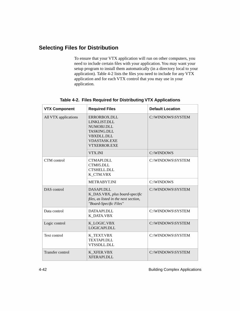
4-42 Building Complex Applications
Selecting Files for Distribution
To ensure that your VTX application will run on other computers, you need to include certain files with your application. You may want your setup program to install them automatically (in a directory local to your application). Table 4-2 lists the files you need to include for any VTX application and for each VTX control that you may use in your application.
Table 4-2. Files Required for Distributing VTX Applications
VTX Component Required Files Default Location
All VTX applications ERRORBOX.DLLLINKLIST.DLLNUMOBJ.DLLTASKING.DLLVBXDLL.DLLVDASTASK.EXEVTXERROR.EXE
C:\WINDOWS\SYSTEM
VTX.INI C:\WINDOWS
CTM control CTMAPI.DLLCTM05.DLLCTSHELL.DLLK_CTM.VBX
C:\WINDOWS\SYSTEM
METRABYT.INI C:\WINDOWS
DAS control DASAPI.DLLK_DAS.VBX, plus board-specific files, as listed in the next section, "Board-Specific Files"
C:\WINDOWS\SYSTEM
Data control DATAAPI.DLLK_DATA.VBX
C:\WINDOWS\SYSTEM
Logic control K_LOGIC.VBXLOGICAPI.DLL
C:\WINDOWS\SYSTEM
Text control K_TEXT.VBXTEXTAPI.DLLVTSSDLL.DLL
C:\WINDOWS\SYSTEM
Transfer control K_XFER.VBXXFERAPI.DLL
C:\WINDOWS\SYSTEM
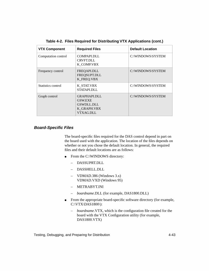
Testing, Debugging, and Preparing for Distribution 4-43
Board-Specific Files
The board-specific files required for the DAS control depend in part on the board used with the application. The location of the files depends on whether or not you chose the default location. In general, the required files and their default locations are as follows:
● From the C:\WINDOWS directory:
– DASSUPRT.DLL
– DASSHELL.DLL
– VDMAD.386 (Windows 3.x)VDMAD.VXD (Windows 95)
– METRABYT.INI
– boardname.DLL (for example, DAS1800.DLL)
● From the appropriate board-specific software directory (for example, C:\VTX\DAS1800\):
– boardname.VTX, which is the configuration file created for the board with the VTX Configuration utility (for example, DAS1800.VTX)
Computation control COMPAPI.DLLCRVFT.DLLK_COMP.VBX
C:\WINDOWS\SYSTEM
Frequency control FREQAPI.DLLFREQSUPT.DLLK_FREQ.VBX
C:\WINDOWS\SYSTEM
Statistics control K_STAT.VBXSTATAPI.DLL
C:\WINDOWS\SYSTEM
Graph control GRAPHAPI.DLLGSW.EXEGSWDLL.DLLK_GRAPH.VBXVTXAG.DLL
C:\WINDOWS\SYSTEM
Table 4-2. Files Required for Distributing VTX Applications (cont.)
VTX Component Required Files Default Location
4-44 Building Complex Applications
– Engineering units definition files (SENSx.DEF)
● From the VTX directory (by default, C:\VTX):
– CALL32.DLL
– ADVAPI32.DLL
● From the VTX\KMM directory (by default, C:\VTX\KMM):
– KMMSETUP.EXE (Keithley Memory Manager utility)
– KMMSETUP.HLP (Windows 3.x)
– VDMADW95.HLP (Windows 95)
● Any other files that the board software may require
If you cannot locate a board-specific file, you can search for the file using one of the following options:
● The Search option available in the File menu of the Windows 3.x File Manager
● The Find option available from the Start menu of the Windows 95 task bar
● The Search option available from the File menu of the Windows 95 Explorer
Alternatively, display the METRABYT.INI file using any text editor. This file contains the complete path to these files for each board family.
Caution: Be extremely careful when viewing the METRABYT.INI file with a text editor. Any inadvertent changes to the file can cause problems for VTX applications using the DAS and CTM controls and the boards whose support files are listed in this file.
INI Files
The VTX.INI file is required for a VTX application to operate on the target PC. If the application uses the DAS control, a METRABYT.INI file is also required. Examine the contents of these two files to determine the tasks required of your installation program. You may want to install a copy of your VTX.INI file. However, if you do this, ensure that the paths
Testing, Debugging, and Preparing for Distribution 4-45
stored in the INI file match the installed locations of the respective files on the target computer.
It is strongly recommended that installation programs place the two INI files in the WINDOWS directory of the target computer.
You may want to reduce the contents of the METRABYT.INI file if your application supports a subset of the boards listed in your own METRABYT.INI file.
Note: If you do not want your application to display VTX error and warning messages, ensure that you disable these options in the appropriate line of the VTX.INI file that accompanies your application.
It is anticipated that you will create your own error messaging and online help for your VTX applications. However, if you plan to let your application display VTX error and warning messages with help buttons, you must include the help files (extension HLP) for the respective VTX controls. Look at the VTX.INI and METRABYT.INI files to determine the names and locations of these help files. In addition, you must install the VTXHLP.DLL file in the WINDOWS\SYSTEM directory of the target computer.
VDMAD.386 File (Windows 3.x)
The VDMAD.386 file is required for VTX applications running under Windows 3.x. Whether you need to distribute this file with your application depends on whether or not VTX software is already installed on the target computers. Follow the instructions in the section below that applies to the computers on which your application will be installed.
VTX Software Already Installed
For applications that will run on computers that are running Windows 3.x and VTX software, you do not need to include the VDMAD.386 file with your distribution files because the VTX software installs it. However, users of your application should ensure that sufficient memory is reserved for the application by using the KMM (Keithley Memory Manager) window of the VTX Configuration utility.
4-46 Building Complex Applications
At installation, the VTX software automatically modified the SYSTEM.INI file and reserved 128K bytes of memory for use by VTX applications. If users of your application need assistance in using the KMM window of the VTX Configuration utility, online help for using the KMM with Windows 3.x is available by clicking the Help button in the KMM window.
VTX Software Not Installed
For applications that will run on computers that run Windows 3.x but do not have VTX software installed, you will need to include the VDMAD.386 file with your distribution files and install it in the WINDOWS directory of the target computer. You also need to install the Keithley Memory Manager (KMM) setup utility on the target computers. The following additional files are required on your distribution disks:
● KMMSETUP.EXE
● KMMSETUP.HLP
Install these files in the same directory as other board-specific software.
To install and set up the KMM, you or the users of the application run the KMMSETUP.EXE utility. This utility updates the SYSTEM.INI files on the target computer so that sufficient memory is available for the VTX-based application. The KMM setup utility provides the same features as the KMM window of the VTX Configuration utility; the KMMSETUP.HLP file provides the online help for the utility.
Alternatively, you can install the VDMAD.386 file and then manually change the [386Enh] section of the SYSTEM.INI file on the target computer, as follows:
1. Replace the line device=*vdmad with the following line:
device=[full path and name of vdmad.386]
2. Add the following line:
KEIDMAHEAPSIZE=x
where x is the amount of memory (in K bytes) that you want the VDMAD to allocate.
Testing, Debugging, and Preparing for Distribution 4-47
VDMAD.VXD File (Windows 95)
The VDMAD.VXD file is required for VTX applications running under Windows 95. Whether you need to distribute this file with your application depends on whether or not VTX software is already installed on the target computers. Follow the instructions in the section below that applies to the computers on which your application will be installed.
VTX Software Already Installed
For applications that will run on computers that are running Windows 95 and VTX software, you do not need to include the VDMAD.VXD file with your distribution files because the VTX software installs it. However, users of your application should ensure that sufficient memory is reserved for the application by using the KMM (Keithley Memory Manager) window of the VTX Configuration utility.
At installation, the VTX software automatically modified the Windows 95 Registry and the SYSTEM.INI file and reserved 128K bytes of memory for use by VTX applications. If the users of your application need assistance in using the KMM window of the VTX Configuration utility, online help for using the KMM with Windows 95 is available by clicking the Help button in the KMM window.
VTX Software Not Installed
For applications that will run on computers that run Windows 95 but do not have VTX software installed, you will need to include the VDMAD.VXD file with your distribution files and install it in the WINDOWS directory of the target computer. You also need to install the Keithley Memory Manager (KMM) setup utility on the target computers. The following additional files are required on your distribution disks:
● KMMSETUP.EXE
● VDMADW95.HLP
Install these files in the same directory as other board-specific software.
4-48 Building Complex Applications
To install and set up the KMM, you or the users of the application run the KMMSETUP.EXE utility. This utility updates the Windows 95 Registry and SYSTEM.INI files on the target computer so that sufficient memory is available for the VTX-based application. The KMM setup utility provides the same features as the KMM window of the VTX Configuration utility; the VDMADW95.HLP file provides the online help for the utility.
X-1
Index
Symbols
(More) property
3-10
A
About property
3-10
accepting user input
4-21
accessing board-specific information
xv
accessing VTX online helpfrom the Keithley VTX program group in
Windows 3.x
xiii
from the Windows 95 desktop
xiv
from Visual Basic
xiii
Add New Board dialog box
1-9
adding a control to an application manually
1-19
aliaschanging
1-11
definition
1-11
Analog In processVTX_SetDASChanRange function
4-17
VTXGetDASChanRange function
4-18
Analog In process, example
4-33
Analog Out processVTX_SetDASChanRange function
4-17
VTXGetDASChanRange function
4-18
Analysis module
3-7
applicationsdebugging
4-40
disabling VTX options for distribution
4-41
planning
4-2
selecting files for distribution
4-42
Applications Engineering
xvii
ArmState propertydefinition
3-10
example
4-22
preventing VTX controls from starting again
4-25
starting VTX controls
4-24
,
4-25
using with multiple forms
4-11
arrays, declaring
4-18
assumptions (tutorial)
2-1
AUTOLOAD.MAK, adding VTX controls
1-21
B
Back to DAS button
xvi
backing up the master disks
1-4
backup commands
1-4
Board Specifics button
xvi
board-specific software, installing
1-5
Breakpoint, using with VTX
4-40
C
calibration
1-14
changing an alias
1-11
changing the configuration of a registered board
1-10
changing the order of multiple connections
4-8
checking system requirements
1-2
checking the package
1-3
ClearInputs property
3-10
Click event procedures for command buttons
4-25
code examplesstarting VTX controls
4-25
stopping VTX controls
4-25
X-2 Index
code module, as used in this guide
4-1
code, writing
4-12
command buttonssetting properties (tutorial)
2-16
command buttons, for starting and stopping VTX controls
4-24
,
4-25
complex applications
4-1
Computation control
3-7
concept summary
3-30
configuration utility
3-7
configuration, changing
1-10
configuring boards for use with VTX
1-7
configuring VTX options
4-41
connect the VTX controls (tutorial)
2-22
connecting VTX controls (additional operations)
4-6
connection points
3-22
to
3-25
,
3-31
connection types
3-21
connections
3-20
to
3-26
changing the order
4-8
definition
3-16
,
3-31
deleting
4-11
displaying the order
4-7
drawing across forms
4-9
overview
3-6
control connections
3-21
control input connection points
3-22
control output connection points
3-22
control properties
3-8
control, passing
3-16
,
3-30
controlslist of filenames
1-18
loading manually
1-19
location of VBX files
1-20
conventions used in this guide
xi
conversion equations
1-12
Counter/Timer (CTM) control
3-6
creating your first VTX application
2-1
CtlConnection property
3-10
CtlVersion property
3-10
CTM boardsalias
1-11
changing configuration
1-10deleting a registered board 1-10registering and configuring for use with
VTX 1-7CTM control 3-6
DDAS Base Module 3-6DAS Base module 3-5DAS boards
alias 1-11calibration 1-14changing configuration 1-10configuring 1-7deleting a registered board 1-10families 1-9installing hardware 1-17registering 1-7
DAS control 3-6, 4-16, 4-17, 4-18setting properties (tutorial) 2-11
DAS Hardware configuration window 1-8, 3-7
DAS-Demo Device 3-7data 3-17 to 3-20data connections 3-21Data control 3-6
using to manage data flow 3-16data conversions, setting up 1-12data display 4-27data element 3-17data group 3-17data input connection points 3-22data output connection points 3-22data set 3-17data set appending 3-18DataConvType property 1-12
X-3
DDE process, example 4-35debugging VTX applications 4-40default alias 1-12Delete key, using with connections 4-11deleting a connection, line, or wire 4-11deleting a registered board 1-10design the user interface (tutorial) 2-3designing the user interface (complex
application) 4-3destination controls 3-14, 3-30dialog boxes for errors, enabling and
disabling 4-41disabling error dialog boxes for distributing
VTX applications 4-45displaying data 4-27displaying status 4-27displaying the order of multiple connections
4-7distributing applications 4-42dragging, definition 2-6drawing a line/connection/wire between
VTX controls 2-22drawing interform connections 4-9drawing lines, wires, or connections 4-6
Eelement, data 3-17, 3-30End statement 4-25engineering units 1-12equations, specifying 1-12error message dialog box 4-41errors 4-36 to 4-39
dialog boxes 4-41handling 4-36invalid property settings 4-6process overrun 4-37Transfer control and array dimensions
4-23
event counter 3-6events 4-13 to 4-15
CTM control 4-15returning status information 4-27Text control 4-16
execution errors 4-36
Ffilenames, VTX controls 1-18files required for distributing VTX-based
applications 4-42form properties, setting (tutorial) 2-9forms
loading 4-11recommendations for using 4-3
frame control (Visual Basic) 4-6Frequency control 3-7frequency measurement 3-6functions 4-17
Ggetting additional help xviiGraph control 3-7
displaying data 4-27Graph module 3-7group, data 3-17, 3-30
HHalt property 3-10, 4-25handling errors 4-36hardware installation 1-17hCtl property 3-10help system xii
X-4 Index
Iinput connection points 3-22INSTALL.TXT file 1-1installation procedure 1-4installing hardware 1-17installing hardware for use with VTX 1-6installing VTX software 1-4 to 1-6integrated controls 3-30interform connections 3-26 to 3-29
displaying information 3-29example 3-27, 3-28, 4-10
invalid property settings 4-6
KKeithley Memory Manager window 1-15,
3-7Keithley MetraByte Applications
Engineering xvii
Llines
definition 3-16deleting 4-11drawing 4-6drawing across forms 4-9
lines, see connectionsloading forms 4-11loading VTX controls 1-18loading VTX controls automatically 1-21locating VTX control files 1-20Logic control 3-6
using to manage program flow 3-16
Mmemory, reserving 1-15More Properties window 3-11moving data between VTX controls 3-18moving data to and from the VTX
environment 3-19multiple connections 3-25multiple forms in an application 3-29
NNDataDone event 4-16
Oonline help system xiioperation-specific properties 3-11order of multiple connections, displaying 4-7ordering connections 4-8output connection points 3-22overview of the application (tutorial) 2-2overview of VTX system 3-1overview of VTX tools 3-5
Pplanning the application 4-2preparing to install VTX software 1-1preparing to use boards with VTX software
1-6Procedure Step, using with VTX 4-40
X-5
proceduresconnecting VTX controls 2-22deleting connections, lines, or wires 4-11drawing connections, lines, or wires
across forms 4-9installing VTX software 1-4setting properties at run time 2-24setting up an application with multiple
forms 4-11writing code for a ProcessDone event
procedure 4-22process errors 4-36process overrun error 4-37Process property 3-10process source, changing at run time 3-13process sources
definition 3-30overview 3-3
process warnings 4-36ProcessCTMDone event 4-15ProcessDone event 4-14
showing status, example 4-27writing code in the event procedure 4-22
ProcessError event 4-15processes
definition 3-30overview 3-3starting 4-24
processes and process sources 3-3ProcessSrc property 3-10program control 3-16, 3-30program control in the VTX environment
3-16properties
control 3-8operation-specific 3-8setting at run time (in code) 2-24
properties common to all VTX controls 3-10properties of VTX controls 3-8Properties window
example with description 3-9pulse generation 3-6
RREADME.WRI file 1-5registering and configuring boards 1-7reserving memory 1-15
SSelect Board button xvselecting files for distribution 4-42sensor definitions 1-12Sensor Definitions window 1-13set the properties (tutorial) 2-9set, data 3-17, 3-30setting properties 3-8setting properties at design time 4-5setting properties at run time (in code) 2-24Settings Box (Properties window) 3-9simulating data acquisition operations 3-7Single Step, using with VTX 4-40sizing handles 2-5source and destination controls 3-14source controls 3-14, 3-30specifying engineering units 1-12starting VTX controls 4-24
example 4-25Statistics control 3-7status of operation, displaying 4-27Status property 3-10, 4-27stopping VTX controls 4-25
example 4-25structure of data in the VTX environment
3-17summary of VTX concepts 3-30Switch process (Data control) 3-16system requirements 1-2SYSTEM.INI file 1-17
X-6 Index
Ttechnical support xviitesting, debugging, and preparing for
distribution 4-39Text control 3-6
displaying data 4-27events 4-16setting properties (tutorial) 2-14
thermocouples, setting up conversions 1-12time interval measurement 3-6Transfer control 3-6
dimensioning Visual Basic arrays to receive data 4-23
moving data for display 4-27starting a VBArray process 4-24VTX_SetXferVBArray function 4-18
troubleshooting, error handling in code modules 4-38
tutorial assumptions 2-1
UUninstall program 1-6Up to DAS button xviuser input 4-21using online help xii
VVB Array process
example 4-34VTX_SetXferVBArray function 4-18
Visual Basic arrays, declaring 4-18Visual Basic Toolbox, with VTX control
icons displayed 2-4VTX Configuration utility 3-5, 3-7VTX control filenames 1-18VTX control files, location 1-20
VTX controlscommon properties 3-10connecting 4-6drawing lines 4-6icons (illustration) 2-4loading manually 1-19properties 3-8starting 4-24text displayed in control 2-5wiring 4-6
VTX environment 3-1, 3-30VTX events 4-13 to 4-15VTX functions 4-17VTX Options window 3-7, 4-41VTX options, enabling and disabling 4-41VTX system overview 3-1VTX_GetDASChanRange function 4-18VTX_SetDASChanRange function 4-17VTX_SetXferVBArray function
definition 4-18starting the Transfer control 4-24
Wwarning message dialog box 4-41warnings 4-14, 4-36 to 4-39wires
definition 3-16deleting 4-11drawing 4-6drawing across forms 4-9
wires, see connectionswiring VTX controls, how to 2-22write the code (tutorial) 2-24writing code 4-12