vlba technical report no. 37 vlba sampler module d121 alan
TRANSCRIPT

VLBA Technical Report No. 37
VLBA Sampler Module D121
Alan E.E. Rogers November 1988


VLBA SAMPLER MODULE D121
Alan E.E. Rogers November 1988
Table of Contents
Drawing List .............................................Specifications ..........................................General Description.....................................Theory of Operation.....................................Circuit Deta il s..........................................Input and Output Connections and Power Levels. . .Test Procedures..........................................Replacement Instructions ..............................Parts List ................................................Data S h ee ts................................................
Drawing List:
Drawing Number
542205001542205002 54220Q003 54 2 2 0M004 54 2 2 0M005 54220M006 54220M007 542201009 54220S010 54220M011 54220M012 54220Q013 54220S014
Title
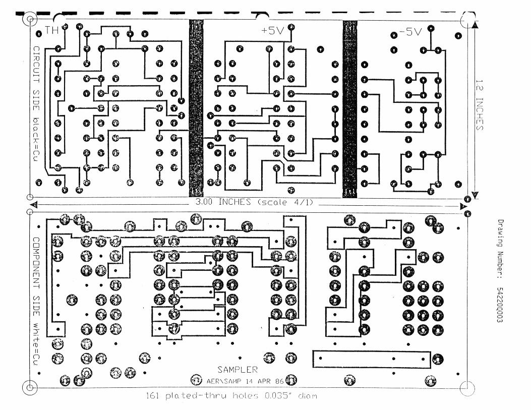
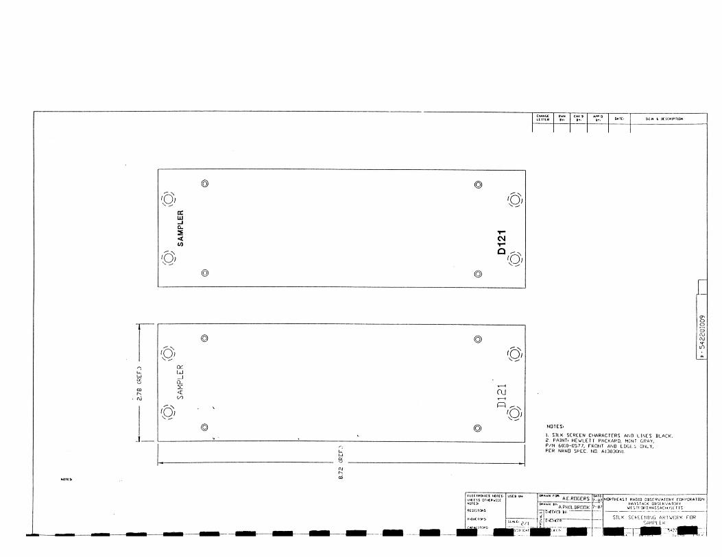
A/D Conv/Sampler Clock A/D Conv/Sampler SamplerSampler Front Panel SamplerLong PC Support Bars Short Support Bars Sampler Front Panel Sampler Rear Panel Mounting plate Sampler Clock 1 PPS timing
Type
Circuit Diagram Circuit Diagram PC Artwork Drilling Plan Assembly Mechanical Mechanical Silk Screen Artwork Block Diagram Mechanical Mechanical PC Artwork Timing diagram
Specifications:
Sampling Jitter and Drift Differential Error Between Channels Sampling Level Accuracy (after trimming) "Magnitude" Bit ThresholdEncoding (From Most -ve to Most +ve signal)
< 0.2 ns< 2 ns< 50 microvolts 2 00 mv00,01,10,11
General Description:
The sampler module digitizes the eight baseband signals from four converters (two modules are needed to support eight converters). The
1

sample clock is derived from the 3 2 MHz synthesizer module and distributed to each A/D converter section. Each A/D converter/sampler uses three comparators with voltage thresholds of -200,0,+200 mv respectively.
Theory of Operation:
The sign bit is the output of one comparator while the least most significant bit is derived from all three comparators according to the logic equation:
Circuit Details:
The comparators are Analog Devices AD9 685D. The clock and reference signal are distributed from the center board. Clock signals are terminated in 50 ohms (the Thevenin equivalent) to -2 volts at the end of each line.
I/O Connections - 20 Pin Amp Connector
LSB B.A + (COMPLEMENT(B)) .C
where
B = sign bitA = comparator with 2 00 mv threshold C = comparator with -2 00 mv threshold
Pin # Function
12345678
91011121314151617181920
GND+5v (350 ma)32 MHz Clock Input (1 Volt p-p) NCSYNC Input (1 Volt p-p)USB from Converter #1 LSB from Converter #1 -5v (2400 ma)USB from Converter #2LSB from Converter #2USB from Converter #3LSB from Converter #3USB from Converter #4NCNCNCNCNCNCLSB from Converter #4
2

I/O Connections - 40 Pin (Balanced ECL Outputs)
Pin # Function
1 SYNC SIGN (-ve2 SYNC SIGN (+ve3 SYNC MAGN (-ve4 SYNC MAGN (+ve5 USB1 SIGN (-ve6 USB1 SIGN (+ve7 USB1 MAGN (-ve8 USB1 MAGN (+ve9 LSB1 SIGN (-ve
10 LSB1 SIGN (+ve11 LSB1 MAGN (-ve12 LSB1 MAGN (+ve13 USB3 SIGN (-ve14 USB3 SIGN (+ve15 USB3 MAGN (-ve16 USB3 MAGN (+ve17 LSB3 SIGN (-ve18 LSB3 SIGN (+ve19 LSB3 MAGN (-ve20 LSB3 MAGN (+ve21 CLOCK (-ve22 CLOCK (+ve23 GND24 GND25 USB2 SIGN (-ve26 USB2 SIGN (+ve27 USB2 MAGN (-ve28 USB2 MAGN (+ve29 LSB2 SIGN (-ve30 LSB2 SIGN (+ve31 LSB2 MAGN (-ve32 LSB2 MAGN (+ve33 USB4 SIGN (-ve34 USB4 SIGN (+ve35 USB4 MAGN (-ve36 USB4 MAGN (+ve37 LSB4 SIGN (-ve38 LSB4 SIGN (+ve39 LSB4 SIGN (-ve40 LSB4 MAGN (+ve
Test Procedures:
Check symmetry of threshold levels by counting the number of zeroes and ones for each bit of each channel via the decoder/data buffer.
3

Replacement Instructions
Use "solder wick" to remove defective components.
Parts List:
Data Sheets:
AD9685BD
4

CHANCELETTER
DWNBY
CHK'DBY
APP'DBY
DATE O.C.N. k DESCRIPTION
—5v. 120 82-5V. 120 82 + 5V. -5V.
N O T E S :
1. ALL CAPACITORS .01 uF UNLESS OTHERWISE NOTED.2. ALL RESISTORS ARE 330 OHMS UNLESS OTHERWISE NOTED.
ELECTRONIC NOTES: UNLESS OTHFRWISC NOTED:
RESISTORS:
CAPACITORS:
INDUCTORS:
USED ON
SCALE_____ NONECLASSlf ICA DON
DRAWN FOR: DATE:A. E. ROGERS 7 -8 7
DRAWN BY:A Pllll.DROOK 7-87
CHECKED BY:
V PRO.iCCTo£ ENGINE 1 R'it ______
NORTHEAST RADIO OOCCRVATORY CORPORATION HAYSTACK OOSERVATORY
WCSTKOHD, MASSACHUSE 1 IS
A/D CONVE'RTER/SAMPlER CLOCK & REF. VOLTACE DISTRIBUTION
AfK\ADCOM$AM
,42?0S001
owe NO
5422
0S00
1

DC* 1 [*SC*lPMON
5V. -\/W
01 01
STCL
02
02
oy
-tv.
-r— 2
"SION"(B)
"MACfJ"( u a + a c )
10131 — 5 V, r
N O ttl.
1 • O F F S E T TRIM A P P R O X IM A U 'L Y 5 0 K2 AIL CAPACITORS ARl OOluF UNILSS
OTHERWISE NOTfO.i ALL RESISTORS ARE 330 OHMS UNLESS
OTHERWISE NOTED 4 + 2.4K OrfSET 1KIM TO ♦ 3V
FOR SYNC CHANNEL (lOOmV OFfSCT).
FOLLOW HOID
WITH GATE DELAY FCUOW HOIO
X I Z D C
CLOCK OUT (CLOCK) _r
CllCTPUOCS rCICS.uni rss ot»««vistNOK t>
MlSISfORS'
IK Dl<. 1 OH Vm ip s
NW lHCAST WADin QbSlkVATOKf CQRPO»AlIOri k a y STaCk 08SCKVAfORf
VC S If l*D .H A iSA O « JS ( T IS
■ 220
S002
m
oo
00 INCHES (sca le 4/1)
0 - 5 V ?
o ©-H • 1*1P o©-------- 1 © J© <
1 0 —j 1 0 —0 iO O O iO 1 o $ <
I © o1 o — I rO ©—<
& ©__^
© © -
© -q® % — @
• © @SAMPLER
@ A ER XS AM P M APR 8 6 @
161 pla'tecl-thru holes 0.035" clion
ro
z:nxH I00
Drawing
Number:
54220Q003

t- —
- o c
.33 I— .692
2.09 — - 2.44 --- 2.78
NOTES .125 THICK ALUM. 606I-T6 REWOVC ALL DURRS AND SHARP EDGES.
YELLOW CHROMATE CONVERSION ALL OVER
DCN lr DtSCRlPtKX
.213 DIA THRU 9 0 ° CSK. TO .062 DEEP FARSIDE (4 ) "d" HOLES.
.166 DIA. THRU 82 ° 5 °C S K .TO .284 DIA. (4 ) "C “ HOLES.
DETAIL "A ”
L
.375- .343
CUT-OUT FOR KINGS-153 BNC
CONNECTOR
E
O
SHU* NO ICS. UNLESS OlMlRwiiC SP£CJf i£0
1. OlM£NcjONS AHE IN INCHES2. TOl £RAN< £ ON CHMt HjiCHS
fRACHONAL f 1/64 DECIMAL XX t .01 DECIMAL XXX t 005 ANGULAR ± O'JO'
3 SURFACE ROUGhnCSS PER mil-STD-10
4 REMOVE BURNS ANO BREAK SlIAM* £[>01$ 1 /64 MAX
5 S«.HEW iMNtAOS f*[H M il-S T D -9 fl AIL l#U lU *O N $ 10 Af'H Y
OHOflL PlATihC OR Curl - VtKI^ON COa TinG
A.E.ROGERSA.PHil BROOK
*n_ * rxo-J
7-g77-87
NORTHEAST RADIO OBSERVATORY CORPORATION HAYSTACK OBSERVATORY
WESTEORIJ. MASSACHUSETTS
DRILLING PLAN FOR SAMPLER
FRONT PANEL

O CN. * DCSCR»P TiOM
12.815 (REF.)
MP1 THRU MP4ft0-80 D'ND'G HEAD MACH. SCREW X .25 LONG ST’L CAD. PL.MP5 THRU MP8I/O SPLIT LK’WSHR, ST'L CAD. PL.
LONG BAR (2) REQ'D P.C. BOARDS SUPPORT DWG C-54220M006
2.75 (REF.)
— i h “ 500 (REF.) 4— i-4-
3.00 (REF.)
— .700 (REF.)
DASHED LINES
NOTESUAllhlAL S«OP NOTIS. UNICSS 0!>«£RwiSC SPCCJfltD OSIO OH «* r u*
A E ROGERS r - l y NORTHEAST R A D IO K V A T O R Y T O R P O R A TlON1. OlMCNcJOHS AKf INCMeS
0*AWN 0YA .P H Il B R O O K 7 -8 7 HAYSTACK OBSERVATORY
f a c t io n a l t ) / t i o c a u> » t w t:snoRD . MASSACHU j E ITSWClMAl .xxx t 005 ANOMAR 1 O'*)’ /
3. sijpfacc roughness \ S
r» ojtciP . C . B O A R D S S U P P O R T
£IMIL.H *MQ/QH MCA1 THCAlMUfI 5
(NbW tt
M E C H . S U B — A S S E M B L Y4. Rf MOVt Bl'RHS AND liW( A* SmaF«p foots 1/t« MAX
V SORtW lllh l Al'S PI N M U-SID-9 6 AIL 0<MlNSl»jMS to APPLY
-1,0.1 M«n. * p»octss
XALT f u ar
SfruCtURlS S A M P L E RU ihW t Pi * one 0* CfJN - VtHSlO»« COAlINU
OASVl'M itW IHAMA*.c : v i 2 2 0 M O O r >
Ml ft. ANAll^id m ; U .'f C»\. NO K| V
|C-5
4220
M00
5|~]

4 OCSCWlPTKJN
£C DOOoCMC\J
CJ
NOTES

CHANGELCTTCR
D'WNBY
CHK'DBY
A P P DBY DATE D CN l DC S C R IP IIO N
* 2.750 LENGTH IS THE SAME FDR ALL SHORT BARS - MACHINE TOGETHER
<2 PER END)
1. MATERIAL: ALUM. 6061-T62. FINISH. CLEAR ALDDINE
SHOP NOTES. UN LESS OTH ERW ISE SPEC K IED
I. DIMENSIONS ARE IN INCHES i. TOLERANCE OH DIMENSIONS
FRACTIONAL t 1/64 DECIMAL XX 1 01 DECIMAL .XXX 1 OOO ANGUl AR 1 0’ 30'
3 SURE ACE ROUGHNESS PER M IL-S1D-I0
4. R IM O V E BURKS AND BREAK SHARP E UGLS 1/64 MAX
3 SCREW 1MRCADS PER M IL-STD-9 6 ALL DIMENSIONS TO AF'PLY
B fEO R E P I AUNG OR CONVERSIO N COATING.
63Mf XT AS SC M DL i
___FU LL_Cl AS'.lf ICMIUN
AE.ROGERSA.PHIl. BROOK
DAIE
2 /8 6CMCCKCD IT
MAR I (-MJCCIS
S1KUCIURCS
MfCH A/IA1 T S15
NORTHEAST RADIO OBSERVATORY CORPORATION HAYSTACK OBSERVATORY
VESTFORD. MASSACHUSETTS
SHORT BAR P.C, BDARD SUPPORT
SAMPLER
MRNSBARSAMI
BDWG. SIZE
^ P P O M Q O LDuii r-n
E
NOTES.1. SILK SCREEN CHARACTERS AND LINES BLACK.2. P A IN T . H E W L E T T P A C K A R D . M I N I CiRAY,P/N 6010-0577, FRONT AND EDGt i [INLY,PER NRAO SPEC. NO. A13030N1.
riCCTPONICS fCTCl. UU fSS OlHtRVUC NUltD-
USCB Or* w a v n raft. A £ RQGCRS OAIC.7-07
7-07
NQRTHCAST RADIO OBSCRVATtlkr CCJKH0KATIUN HAYSTACK UBSLK'VA T{)ttT
VCSTrOPD.MASSACH.IM T ISOK
" ' A P H IL BROOK
iNoucin^s*"CVifCifCfi Jy>
S ILK SCkLXNIfJG ART WORK FORS am p 1.1rs u t , 2 / 1
C'Cl'lTB
■- INC A r K CT. -’‘d P I r .
- 542
2010
09

■ 3
3
> 3
3
10
20
SYNC
USB1 (5 )
L S B l (5 )
USB3 <7>
LS B 3 (7 )
32MHz IN
USB2 <6)
3LS B 2 (6 )
1 3 3USB4 C8)
3I.SB4 <8)
2 > 8 >
+5 (350ma)-5 (2400na)
OND>— I
SAM PLER 0
CLOCKDISTR.
1 SYNC?341 USB1?341 L S B lP341 USB3?34I L S B 3?341 T T n rk rP CLOCK
GNDGND
1 U SB2P341 L S B 2?341 IJS It 4P341 1 5s n 4?34
I><2x J
56
k e910 11 12
X C 141516
I7>\ 10 ^ 19 ^<20
21 222324
. ^25X 26
28 / 29
30 /31
V 3 2/ 33
V 34 / 35
> \ 36/ 37
> k 30 / 39
40 PIN 'BU LKH EA D '
V IR E S FROM PC BOARDS 3M 3432-4305(OUTPUT P IN NUMBER:
SYNC
USB1
L S B l
USB3
L S B 3
C LOCKCLOCKGNDGNDUSB2
LS B 2
USB4
LSB4
DCH. 1 K SCRIPT 10H
SIGNS IGNMAGNMAGN
SIGNS IG N _'MAGN*MAGN
s MI A
+ G GN N
V1 1
1 J*0 1
0 0
____ +ve THRESHOLD
0 V O LT S
___ -vt? THRESHOLD
r
CODE
( llC TM XIC l nuH I. u<« is s Olicftvr.c
USC» Of. w'* v " ,0M' AT PfiCtfcS DAl(.;-«/ n iK iiiC A s r r a d io o b . fx v A io k r n w o P A i iu r i
«l SI HORS.
IHI'UCIUKJ.
*.VN if.A Fu ll bklJfK J - Q /
»v«u i a l k Ofa J KVATUfcr VC 11» I*- L>lAi^AC»«J<( 1 IS
V SAtM'l f ksc a* r- r*«ttr/r* (A/D C (INVt R if k>
t Al'A«. I KJKS*
! V i l a hi ii* C
u a ;: i» ua 1 iii« MKMAHtmm J |l K I.-'POSUIO]
"542
20S0
10


|D-
54?2
0mO
I2

n□
"0□zm
00 I— Iom£T<+0)Ito
©
©
a
L J 1 i P 5 ‘ L _ @ ©
© © @ © © o© © © © o o © ® ©
@ • © © ® o © o © @
© •\ © o © © © o o
• 0 ©
o o © ■ o © ®
© * • • • • •
•
. i ®• ® ©
m
Drawing
Number:
54220Q013

9685S SAMPLE DATA HERE
SEE NOTE //1
ECJlO')K)CD
=5U)
rn
NOTES: 1. MARGIN ON 1PPS +1 5ns (EARLY) TO ■
FROM 32M
FROM 32M MODULE -20ns (LATE).
OUTPUT PIN ON 10131
2 32M PIN 3 ON 9685S
DWG. LAST CHANGEDSHO P NOTES: UNLESS OTHERWISE SPECIFIED
1. DIMENSIONS ARE IN INCHES2. TOLERANCE ON DIMENSIONS
FRACTIONAL ± 1/64 DECIMAL .XX ± .01 DECIMAL .XXX ± .005 ANGULAR ± 0 '30’
3. SURFACE ROUGHNESS PER MIL—ST D -10
4. REMOVE GURRS AND RREAK SHARP EDGES 1/64 MAX.
5. SCREW THREADS PER M IL-STD-96. ALL DIMENSIONS TO APPLY
BEFORE PLATING OR CONVERSION COATING.
USED ON
NEXT ASSEMBLY
wocnrSCALE NONECLASSIflCA tlON
DRAWN fOR A.E.ROGERSD RAW BY C.KOSTKACHECKtD BY
PROJCCT
ENCINEER
MAIL. * PROCESS
STRUCTURES
THERMAL
MECH ANALYSIS
1/88N O R T H E A S T RADIO O B S E R V A T O R Y CO RP ORA TI ON
H A Y S T A C K O B S E R V A T O R Y
WESTFORD, M A S S A C H U S E T T S
1PPS TIMING IN SAMPLER MODULE
PPSTSMD ADWG SI7E
54220S01DWG. NO. K'HV.

Page No. 11/25/88
1
PARTS L IS T FROM DBASE F I L E :PARTS.DBF
REF SUBMOD PART DESC MFR COST QTY TOTAL COST
U06 SA 10104 10104 FAIRCH IT.D 0 . 69 1 0. 69C01 SA 103K 0.01 UF AVX 0 .10 87 8. 70C02 SA 105K 1 UF AVX 0. 32 9 2.88HP SA 1105-7521-003 SMC CABLE PLUG AEP 2.49 10 24 . 90MPX SA 200458-1 BLOCK AMP 3.00 1 3.00MPX SA 200833-4 GUIDE P IN S AMP 0.36 2 0. 72MPX SA 200835-4 GUIDE SOCKETS AMP 0.48 2 0. 96MPX SA 201142-2 SPRING AMP 0.05 11 0.55MPX SA 201143-5 COAXICON P IN AMP 2.70 11 29. 70MPX SA 202394-2 HOOD AMP 1.04 1 1.04MPX SA 202422-1 POWER PINS AMP 0.50 4 2.00MPX SA 328666 FERRULE AMP 0.08 11 0.88SS SA 542201009 F .P .S IL K SCREEN NYES 100.00 1 100.00MS SA 54220M004 FRONT PANEL HAYSTACK 100.00 1 100.00MS SA 54220M005 PC BOARD SUPPORT HAYSTACK 100.00 1 100.00MS SA 54220M011 REAR PANEL HAYSTACK 100.00 1 100.00MS SA 54220M012 CENTER PLATE HAYSTACK 100.00 1 100.00U04 SA AD9685BD 9685 ANALOG DEV 11.30 27 305.10PC SA AER\SAMP PC BOARD PACLAB 40.00 9 360.00PC SA AER\SCLK PC BOARD PACLAB 40.00 1 40.00MS SA C53306M013-2UA FRONT PANEL PREC.MACHINE 20.00 1 20.00MS SA C53306M014-2UA PERFORATED COVER PREC.MACHINE 10.00 2 20.00MS SA C53306M015-2UA MODULEREAR PANEL PREC.MACHINE 20.00 1 20.00MS SA C53306M016 BAR SUPPORT PREC.MACHINE 10.00 4 40.00MS SA C53306M017 SID E PLATE PREC.MACHINE 10.00 2 20.00U02 SA MC10101L 10101 MOTOROLA 1.00 2 2.00U01 SA MC10116L 10116 MOTOROLA 1.14 1 1.14U05 SA MC10131L 10131 MOTOROLA 1.14 9 10.26U03 SA OP-27EN OP-27 ANALOG DEV 7.15 1 7.15R03 SA RCR05G100J 10 OHMS 1/8W AB 0.20 1 0.20R05 SA RCR05G121J 120 OHMS 1/8W AB 0.20 4 0.80R02 SA RCR05G122J 1.2K OHMS 1/8W AB 0.20 1 0.20R04 SA RCR05G331J 330 OHMS 1/8W AB 0.20 93 18.60R01 SA RCR05G510J 51 OHMS 1/8W A3 0.20 38 7.60R06 SA RCR05G820J 82 OHMS 1/8W A3 0.20 4 0.80R07 SA RN55D1272F 1 2 .7K OHM 11 CORNING 0.10 2 0.20WORK SA TECH ASSEMBLY HAYSTACK 10.00 20 200.00
*** T o ta l * **1650.07

ANALOGDEVICES Uftra-Fast Comparators
AD9685/AD9687FEATURES2.2ns Propagation Delay - AD9685BD/BH 2.7ns Propagation Delay - AD9687BD 0.5ns Latch Set-U p Tim e Pin-Com patible to Am 685/687 but FASTER + 5V, —5.2V Supply Voltages
APPLICATIONSUltra-H igh-Speed A/D Converters Ultra-H igh-Speed Line Receivers Peak Detectors Threshold Detectors
GENERAL D ESC R IPTIO N
The A D 9685B D /B H and A D 96S7B D are ultra-fast comparators
m anufactured with a high perform ance bipolar process which
makes it possible to obtain incredibly short propagation delay?
and latch set-up times.
The A D 9685B D /B H is a single com parator which is pLn-comparible
with the A m 635, b ut has speed capabilities that far outstrip the
earlier unit. T h e AE)S687BD is pin-for-pin compatible with the
Am6S7 and, like its predecessor, is a dual comparator; its speed
capabilities arc far superior to the A m 687.
Both Analog Devices units have differential inputs and com
plementary outputs fully com patible with ECL logic levels.
Their output current levels 3rc capable of driving 50Cl terminated
transmission lines, and their high resolution make them ideally
suited for a variety of analog-to-digital signal processing applica
tions.
AD9685BD /BH Single Comparator
A latch function allows the A D 9685B D /B H to be operated in a
sample-hold m ode. W hen the Latch Enable (L E ) is ECL H IG H ,
the com parator functions norm ally. W hen the Latch Enable is
driven L O W , its outputs are locked in the logic state dictated
by the input conditions at the tim e of the latch input transition.
If the latch function is not used, the Latch Enable input should
be connected to ground.
In addition to its speed advantages over the earlier Am6S5, the
AD 9685BD /BH also dissipates less power because it operates on
a positive 5 volt supply instead of the 6 volts required by the
AMD device.
AD96S5BD/BH FUNCTIONAL BLOCK DIAGRAM
t w o u m jr s a *c o * f n i m t t t t m o u ia in g f r r i h n a i*A iO O w N «C S JS TO *3 TMfSCftCSISTOrtSMAV • r * € AA »G €0***h-?o04IC O »M *C TfO TO -2 .0V . Oft 200IW2900II CO**CCTIDTO - »JV.
AD9687BD FUNCTIONAL BLOCK DIAGRAM
L> T O t(H X U j| LATC* CNAA4.2
t m cx rrn /T S aac o* i n im o -tt»s a co u»«i * g c r rtP N A Lr u u OOWHMS15TOAS TH€S£ » (SUrO < UM *» B( j* r v f
O SM U rnilC O *W £C T E O TO - 2.0V. C* 7001 UrtOOII CCNN€CTtOTO - U V .
A D 9687B D Dual Comparator
T he latch function of the A D 9687BD provides an a’oiliry to
operate the unit in either a track-hoid or sample-hold mode.
T he latch function inputs arc separated on the two comparators
and are designed to be driven from the complementary outputs
of a standard ECL logic gate. W hen LE is High and LE is
L O W , the normal comparator function is in operation. When
LE is forced LOW and LE is driven H IG H , the outputs of the
comparator being exercised are locked in their existing logical
states, as determined by the input conditions present at the time
of arrival of the latch signal. If the latch function is not used on
either one of the two comparators in the A D 9687B D , the appro
priate Latch Enable input should be connected to ground; the
companion Latch Enable input can be left open.
T he A D 9687BD is basically rwo AD96S5BD/BH units in a
single package and operates in a similar fashion to a pair of the
single comparators.
Q OUTPUT
O OUTPUT
OPERA T10NAL AMPLIFIERS VOL. I, 4-117

(typical @ + 25*C with nominal supply voltages unless otherwiso noted)
A B SO I U ' l t M A X IM U M RA T IN f.S Supply Voli4gct(V(x and V l f ) Pu»cr Duiif^tion Input V ullage Differential Input Voltage Output Curreet 0|<raung Temperature Range StorageTemperature Range
A D 9t>SHf) b H
Z 6V IJ6utW x 5V l.S V 30mA - iO C t -55*Ct-
► I5*C► 150-C
T I E C T R IC A I C H A R A C T ER IST IC S Symbol Mia Trp M a . Mia T>p Maa Unit.
Input Olf>ei Voltage1 V,h -5 ♦ 5 • • mVTemprraiurc ( Axfltctent a v .^/a t 20 *
Input Ollvei Current U 5 ' M AInput BtatCurreni I . 10 20 * * H AInput Voltage Range V cm . -2 5 ♦ 2 5 *Common Mode Reieciioo Ratio CM HR 10 *Input Rctiwarwc R ,n 60 *Input Capaoiancc C,w 1 * pF1 opul Output Logic 1-e-vela
-0 t lOutput H IGH Voltage V oh -0 *Output LO W Voltage Vo*. - 1 15 - 1 65 *
Positive Supply Vulugc Vec ♦ 4 75 ♦ 5 ♦ 5 25 *Negative Supply Voltage Va« -4 9i -5.1 - 5 45 *
YQPoutivc Supply Current l«c IV 2) mANegative Supply Current I t i H )4Supply Voltage RcK'-ttoo Ratio S v* . 60
4)0J i t
Power Dmipation PlMH 210 >00
S W IT C H IN G C H \R \ C T F R IS n C SI’lopagattoo DcUyt^
2 7Input to Outpui H IG H 2 2 1 a*Input luOutput L O W •h * 2 I I ntl^tch Eiuble to Output H IGH t ^ v ( E ) 2 5 ) aaI Jtch Enable toOuipui LO W 2 5 ) na
l^tch EnablePulbe WfcJth 1 2 *
ntMinimum S<t-UpTime 1. 0 5 1MuumuJii HolJ Tinvc U ni
SUTCS‘ItI - 100 *4m'F tvfM liiM* J t l ip w u w H •riik I00»v fuiM,\mV•S|«vU‘itaiM«i u a iM A D ^ It lD I I Il|« . •/*. UtaM k4 )rt I Hikin|4 •**».«D E F IN IT IO N O F T E R M SV ,% IN P U T O F F S E T V O LT A G E-T h e potential difference
required between the input terminal* loob tiin aero potential difference between the output*.
lo« IN P U T O F F S E T C U R k EN T - T h e difference between the current! into the input* when there ti aero potent ul difference between the ouiputi.
! a IN P U T B IA S C U K R E N T - T h e averageo/the twoin|KJt current!. T h it i i a chip detigo trade -oil parameter. Internally, it it desirable tohavc high valuct of I« foe Circuit peiformartcc requirement a; caiernally, it u deair- able to have I* aa tow aa pomble.
V CJ4 IN P U r V O L r A G E R A N G E-The range of input voltage* fur which ofltet and propagation delay •pctificaiiont u c valid.
C M M l CO M M O N M O D E R E JEC T IO N M T IO - T h e ratioo/ u»put voltage range to the peak to peak change in input offset voltage over that range.
R in IN P U T R E S IS T A N C E - T h e rcuiiince looking into either terminal with the other gtounded.
C ,* IN P U T C A P A C IT A N C E-T h e capacitance looking into cither input pin with the other giuunded.
V oh O U T P U T H IG H V O LT A G E-T h e log* H IG H output voltage with an eiternal pull down reaiaior relumed to a negative tuppJy.
Vo, O U T P U T L O W V O L T A G E- T h e logic L O W output vuliagr with au eiternal poll-down tctittor returned toa negative aupply.
K c P O S IT IV E S U P P L Y CURRENT-T>ve current required from the potiiivc lupjdy too|>craic the comparator.
I »a N E G A T IV E S U P P L Y C U R R E N T - 1 he current required (run* tlie negative lupply toO|<rate the comparator.
SVB, S U P P L Y V O L T A G E R E JE C T IO N R A T IO - The ratio of the change in input off tel voltage to tl»e change in power tupply voltage producing it.
Piu»i PO W ER D ISS IP A T IO N - T l» c power diaiipated by the comparator w»ih both outputt in mmaicd in SOohmuo -2V.
tH . IN P U T T O O U T P U T II IG IC D E I- A Y - T > *propagation delay measured Irorn the time the input aignal croavc* t l* input offtei voltage to the 50% point
, of an output L O W to H IG H tranaiiion.I * - IN P U T T O O U T P U T L O W D E L A Y -The
propagation delay m otored fiom tl»e time the input aignal c ro iu i ll.e iaput o ffu l voltage to the 50% point o/an output H IG H to L O W tranaiiion.
tH . ( E ) L A T C H E F M U L E T O O U I P U T IH G I I D E I- A Y - T h e propagation delay inceaured from the 50% point of the Latch Finable (LL )a ig na l L O W to H IG H tranaiiion to the 50% point U an out put L O W to H IG H tranaiiion.
iH - tE ) IATC-11 E N A II 1.1: T O O U T P U T I O W 1)1* I .A Y - Thepropagation delay meatured Irom the 50% point of the Lau h Enable tignal L O W to H IG H Irantition to the 50% point of an ouiput H IG H to I O W tranaiiion.
i ^ E ) M JN IM I IM L A T C H E N A U L E P U I S U W ID T H - T U ■unimum time the I -atch Enable aignal muat be 11IG II to acquire and hold an input aignal.
I, M IN IM U M S liT -U P T IM I: - The minimum time be-fu«e the negative Irani it ion of the I J i i h Enable pul*e that to input aignal m ull be preterit lobe afQuirrd and held at the output*.M IN IM U M I IO L D T IM E - T b e minimum time after the negnive Hamilton of the Latch Enable aignal that an inpot aignal muat remain uru hanged to be acquired and held at the outputs.
O T H E R S Y M B O L S T c Caae Temj<ra
RaV ,V|£V|K
|r.|Mt tnurcc remtance Supply voltagea Poauive aupply voluge Negatt/c aupply voltage
Output bad teivninaiing voltageOutput l»o*l r< tit lance Inpui pulw aiit|'lnuJc Inf*u« wvcrJtive Frequency
TIMING DIAGRAM
The Timing Diagram illustrates > strict of events in the AD968M1D/11H; the (crmj and their relationships are also valid for the AD96H7HD. The relationships which are shown should not be interpreted as "typical", sincc several parameters have multiple values; and the worst case conditions arc shown in the Timing Diagram.The top line of the diagram shows two Latch Enable (I.E) pulses; each is high for “ comparc” and low for “ latch” . The first pulse illustrates the comparc function in which part of the input action lakes place during the “ comparc” mode. The second one illustrates I compare function interval during which there is no change in input.The leading edge of the input signal, shown here as a large amplitude, small ovcrdtivc pulse, switches the comparator after • time interval t()j. Output Q and Q transitions arc essentially similar in liming. The input signal must occur at t lime t, before the latch nailing (falling) edge and, to be acquired, must be
maintained for > lime t|, after that edge. After th, the outpui no longer affectcd by the input status until the latch is again strobed. A minimum latch pulse width of tpw(E) is required the strobe operation, and the output transitions occur after a lime tt>j(E).
TO-IOO
AD0G85BH Pin Configuration Pjckagt Option1 — TO-IOO
PIN CONFIGURATIONS
AD9635BD Pin Configuration Ptckiga Option1 — QI6C
A09687BD Pin Configuntion Package Option1 —0 764
N O T K‘ See Scciion 19 lot pickagc outline infornuilon.