vlt 5000/6000 series contents introduction to vlt 5300 ... 6300-6500 manual.pdf · programming the...
TRANSCRIPT

VLT® 5000/6000 Series
� Contents
Introduction to VLT 5300-5500 / VLT 6350-6550 ............................... 2General warning ...................................................................................................... 2Introduction .............................................................................................................. 3Transportation and unpacking ................................................................................. 4Key diagram forVLT 5300-5500 380-500 V and VLT 6350-6550 380-460 V .......... 6Technical data .......................................................................................................... 7
Mechanical installation ................................................................................ 11Mechanical dimensions ......................................................................................... 11Pre-installation ....................................................................................................... 12Installation site ....................................................................................................... 12Cable site ............................................................................................................... 13Derating for high altitude ....................................................................................... 13Derating for ambient temperature .......................................................................... 13
Electrical installation .................................................................................... 14Electrical installation .............................................................................................. 14Pre-fuses ................................................................................................................ 14Earthing ................................................................................................................. 14RFI switch .............................................................................................................. 14Electrical installation, power cables ....................................................................... 15Electrical installation, enclosure ............................................................................ 16Terminal adapter kit ............................................................................................... 17Tightening-up torques ............................................................................................ 17Installation of 24 Volt external DCsupply .............................................................. 17Installation of brake resistortemperature switch .................................................... 17Cable cross-sectionand length .............................................................................. 18Mains connection ................................................................................................... 19Motor connection ................................................................................................... 20Brake connection ................................................................................................... 21Load sharing connection ....................................................................................... 21Motor and DC coils connections on IP 00 ............................................................ 22Control cable routing ............................................................................................. 23Connection example .............................................................................................. 24Electrical installation procedures ........................................................................... 25Electrical installation, control leads ....................................................................... 26Programming the VLT 5000 ................................................................................... 26Programming the VLT 6000 HVAC ........................................................................ 26Motor start ............................................................................................................. 26
MG.56.A1.02 - VLT is a registered Danfoss trade mark 1

VLT® 5000/6000 Series
� General warning
The voltage of the frequency converter isdangerous whenever the converter is con-nected to mains. Incorrect fitting of the
motor or frequency converter may cause damage tothe equipment, serious injury or death. Conse-quently, it is essential to comply with the instructionsin this manual as well as local and national rules andsafety regulations
1. The VLT frequency converter must be discon-nected from mains if repair work is to be carriedout. Check that the mains supply has been dis-connected and that the necessary time haspassed before removing motor and mains plugs.
2. The [STOP/RESET] or [OFF/STOP] key on thecontrol panel of the VLT frequency converterdoes not disconnect the equipment from mainsand is thus not to be used as a safety switch.
3. Correct protective earthing of the equipment mustbe established, the user must be protectedagainst supply voltage, and the motor must beprotected against overload in accordance with ap-plicable national and local regulations.
4. The earth leakage currents are higher than 3.5mA.
5. Protection against motor overload is not includedin the factory setting. If this function is desired,set parameter 128 to data value ETR trip or datavalue ETR warning. On VLT 6000, set parameter117 to data value ETR trip or data value ETRwarning.Note: The function is initialised at 1.16 x ratedmotor current and rated motor frequency (seeOperating manual).
For the North American market: The ETR functionsprovide class 20 motor overload protection in ac-cordance with NEC.
6. Do not remove the plugs for the motor and mainssupply while the VLT frequency converter is con-nected to mains. Check that the mains supplyhas been disconnected and that the necessarytime has passed before removing motor andmains plugs.
7. Please note that the VLT frequency converter hasmore voltage inputs than L1, L2 and L3, whenloadsharing (linking of DC intermediate circuit)and external 24 V DC have been installed. Checkthat all voltage inputs have been disconnectedand that the necessary time has passed beforerepair work is commenced.
� Warning against unintended start1. The motor can be brought to a stop by means of
digital commands, bus commands, references ora local stop, while the frequency converter is con-nected to mains. If personal safety considerationsmake it necessary to ensure that no unintendedstart occurs, these stop functions are not suffi-cient.
2. While parameters are being changed, the motormay start. Consequently , the stop key [STOP/RE-SET] or [OFF/STOP] must always be activated,following which data can be modified.
3. A motor that has been stopped may start if faultsoccur in the electronics of the frequency con-verter, or if a temporary overload or a fault in thesupply mains or the motor connection ceases.
176FA055.10
Warning:Touching the electrical parts may be fatal - even after theequipment has been disconnected from mains.Also make sure that other voltage inputs have beendisconnected, such as external 24 V DC, load-sharing(linkage of DC intermediate circuit), as well as the motorconnection for kinetic back-up.
Using VLT 5300-5500 / 6350-6550: wait at least 15 minutes
MG.56.A1.02 - VLT is a registered Danfoss trade mark2

VLT® 5000/6000 Series
� IntroductionManual objectivesThe purpose of this manual is to provide the userwith the necessary information to install, programand start up the Danfoss VLT 5300-5500 and VLT6350-6550 frequency converters. This manualshould be read thoroughly before operating, servic-ing or initializing the drives. This manual is intendedfor use along with the Danfoss Operating Instruc-tions Manual for the VLT 5000/6000 frequencyconverters for detailed information.
Who should use this manualThis manual is intended for qualified service person-nel responsible for setting up and servicing theDanfoss VLT 5300-5500 and VLT 6350-6550frequency converters. Qualified personnel have pre-vious experience with the frequency converters andunderstand electrical fundamentals, programmingprocedures, required equipment and safety precau-tions.
Organization of the manualThis manual is arranged in equipment installationand connection sequence. The order of tasks are ar-ranged as follows:• Safety instructions• Transportation and unpacking• Technical data• Mechanical installation• Pre-installation• Electrical installation guidelines• Control cable routing• Connection examples• Electrical installation procedures• Motor start
MG.56.A1.02 - VLT is a registered Danfoss trade mark 3

VLT® 5000/6000 Series
� Transportation and unpackingTo lessen the possibility of damage it is recom-mended that the crated VLT frequency converter islocated as close to the final installation site as possi-ble before uncrating.
Door and ceiling clearances must be consideredwhen moving and installing the VLT frequency con-verter. See below table for the crate dimensions:
Dimensions [mm]:
H W D
IP 00 2096 1219 699
IP 20 / 54 2324 1321 724
Weight [kg]:
VLT5300/6350
VLT5350/6400
VLT5450/6500
VLT5500/6550
IP 00 548 583 628 653IP 20 654 689 734 759IP 54 664 699 744 769
A qualified person with a forklift or other similar liftingdevice will be needed to remove the VLT frequencyconverter from the crate.
To open the crate:• Remove the metal locking tabs that secure the
top panel of the crate, this will give access to thelifting rings on the top of the VLT frequency con-verter.
• On IP 00 versions remove the supporting bracebolted to the lifting rings.
• A forklift or similar lifting device should be used atthis time to ensure the stability of the VLT fre-quency converter while the rest of the crate isremoved. Position the lifting device to the frontside of the crate.
• The VLT frequency converter should be lifted us-ing a spreader bar or other similar lifting device.Lift the VLT frequency converter slightly, using allfour lifting rings, distributing the weight as evenlyas possible.
MG.56.A1.02 - VLT is a registered Danfoss trade mark4

VLT® 5000/6000 Series
Do not lift in this manner.
Proper lifting method.
• Remove the metal locking tabs and the remainingcrate panels.
• On IP 00 versions remove the clear plastic safetybarrier from the front of the unit to prevent thepossibility of breaking during positioning of theVLT frequency converter.
• The VLT frequency converter is now ready to belifted and positioned in the installation site.NOTE: On IP 00 versions there are inductorsbolted to the bottom of the crate. Lift the VLT fre-quency converter high enough to allow clearanceover these inductors.
• Observe cooling and ventilation requirementsgiven in the “Installation Site” section of this man-ual.
• Secure to the floor using the four holes providedin the bottom of the unit. On IP 00 versions se-cure to the panel using the four mounting holesprovided in the back. Refer to the dimensionaldrawings in this instruction manual.
IP 20 and IP 54
All dimensions are in mm.
IP 00
All dimensions are in mm.
MG.56.A1.02 - VLT is a registered Danfoss trade mark 5
VLT® 5000/6000 Series
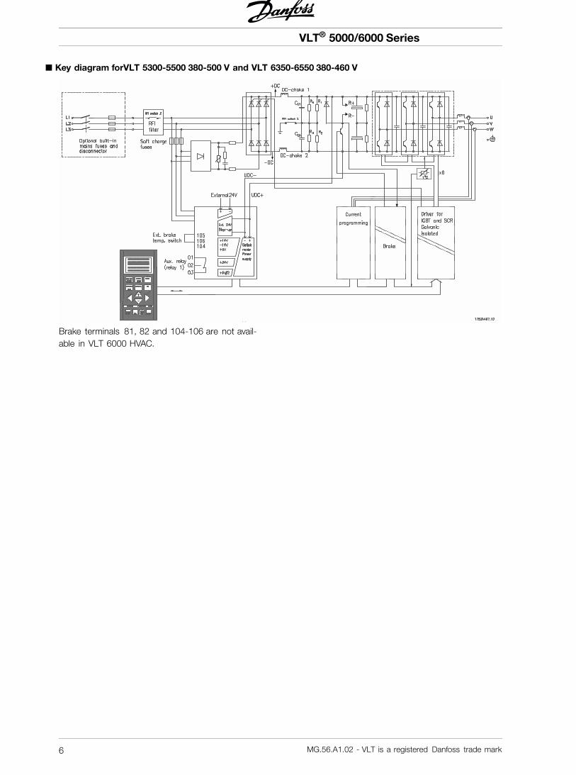
� Key diagram forVLT 5300-5500 380-500 V and VLT 6350-6550 380-460 V
Brake terminals 81, 82 and 104-106 are not avail-able in VLT 6000 HVAC.
MG.56.A1.02 - VLT is a registered Danfoss trade mark6

VLT® 5000/6000 Series
� Mains supply 3 x 380-500 V
According to international require-ments VLT type 5300 5350 5450 5500
Normal overload torque (110 %):
Output current IVLT,N [A] (380-440 V) 480 600 658 745
IVLT, MAX (60 s)[A](380-440 V) 528 660 724 820
IVLT,N [A] (441-500 V) 443 540 590 678
IVLT, MAX (60 s)[A](441-500 V) 487 594 649 746
Output SVLT,N [kVA] (380-440 V) 333 416 456 516
SVLT,N [kVA] (441-500 V) 384 468 511 587
Typical shaft output (380-440 V) PVLT,N [kW] 250 315 355 400
Typical shaft output (380-440 V) PVLT,N [HP] 300 350 450 500
Typical shaft output (441-500 V) PVLT,N [kW] 315 355 400 500
Typical shaft output (441-500 V) PVLT,N [HP] 350 450 500 600
High overload torque (150 %):
Output current IVLT,N [A] (380-440 V) 395 480 600 658
IVLT, MAX (60 s)[A](380-440 V) 593 720 900 987
IVLT,N [A] (441-500 V) 361 443 540 590
IVLT, MAX (60 s)[A](441-500 V) 542 665 810 885
Output SVLT,N [kVA] (380-440 V) 274 333 416 456
SVLT,N [kVA] (441-500 V) 313 384 468 511
Typical shaft output (380-440 V) PVLT,N [kW] 200 250 315 355
Typical shaft output (380-440 V) PVLT,N [HP] 300 350 450 500
Typical shaft output (441-500 V) PVLT,N [kW] 250 315 355 400
Typical shaft output (441-500 V) PVLT,N [HP] 350 450 500 600
Max. cross-section of copper cable to motor, 2 x 150 2 x 185 2 x 240 2 x 300
and loadsharing (380-440 V) [mm 2 ]5 ) 3 x 70 3 x 95 3 x 120 3 x 150
Max. cross-section of copper cable to motor 2 x 120 2 x 150 2 x 185 2 x 300
and loadsharing (441-500 V) [mm2 ]5 ) 3 x 70 3 x 95 3 x 95 3 x 120
Max. cross-section of aluminium cable to motor 2 x 185 2 x 240 2 x 300
and loadsharing (380-440 V) [mm2 ]5 ) 3 x 120 3 x 150 3 x 185 3 x 185
Max. cross-section of aluminium cable to motor 2 x 150 2 x 185 2 x 240
and loadsharing (441-500) [mm2 ]5 ) 3 x 95 3 x 120 3 x 150 3 x 185
Max. cross-section of copper cable to motor 2x250mcm 2x350mcm 2x400mcm 2x500mcm
and loadsharing (380-440 V) AWG]2 ) 5 ) 3 x 2/0 3 x3/0 3 x 4/0 3x250mcm
Max. cross-section of copper cable to motor 2 x 4/0 2x300mcm 2x350mcm 2x500mcm
and loadsharing (441-500 V) AWG]2 ) 5 ) 3 x 1/0 3 x 3/0 3 x 3/0 3 x 4/0
Max. cross-section of aluminium cable to motor 2x350mcm 2x500mcm 2x600mcm 2x700mcm
and loadsharing (380-440 V) AWG]2 ) 5 ) 3 x 4/0 3x250mcm 3x300mcm 3x350mcm
Max. cross-section of aluminium cable to motor 2x300mcm 2x400mcm 2x500mcm 2x600mcm
and loadsharing (441-500 V) AWG]2 ) 5 ) 3 x 3/0 3 x 4/0 3x250mcm 3x300mcm
MG.56.A1.02 - VLT is a registered Danfoss trade mark 7
VLT® 5000/6000 Series
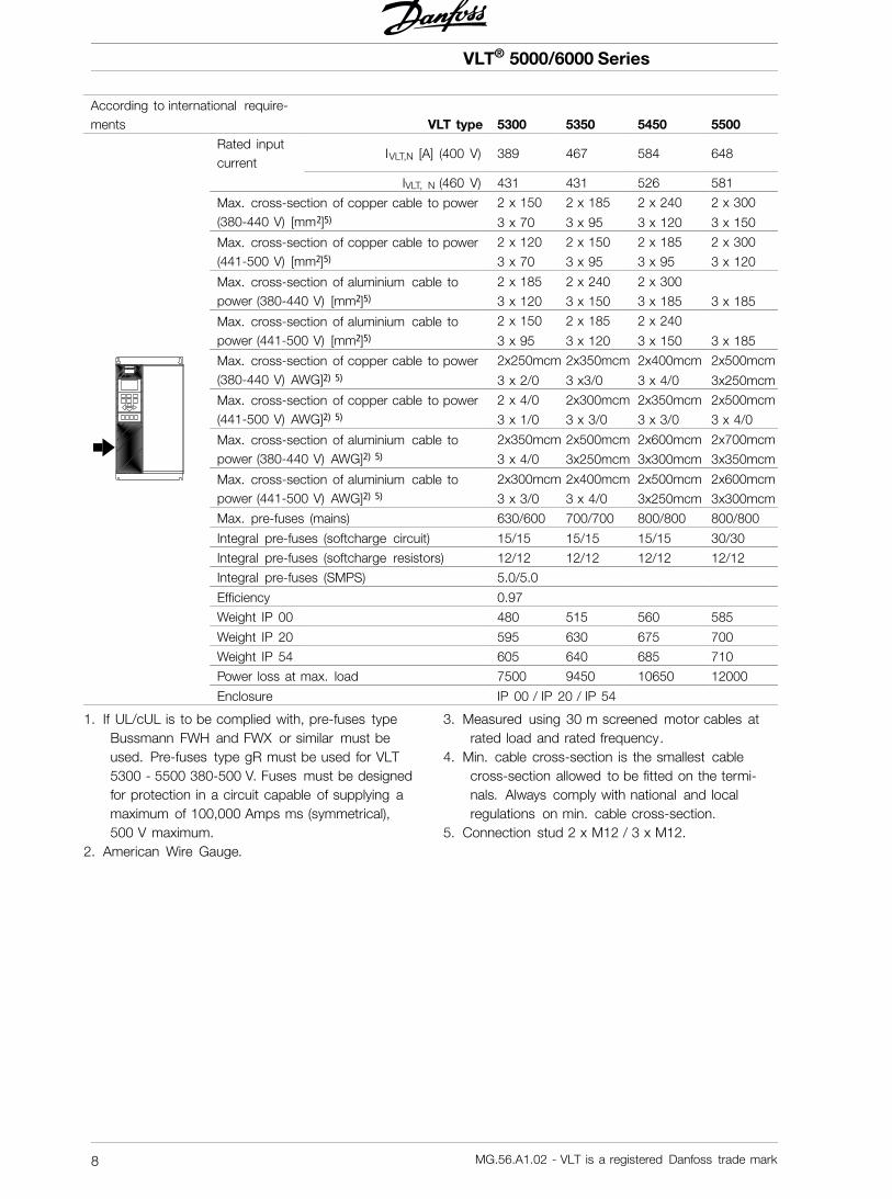
According to international require-ments VLT type 5300 5350 5450 5500
Rated inputcurrent
IVLT,N [A] (400 V) 389 467 584 648
IVLT, N (460 V) 431 431 526 581
2 x 150 2 x 185 2 x 240 2 x 300Max. cross-section of copper cable to power(380-440 V) [mm 2 ]5 ) 3 x 70 3 x 95 3 x 120 3 x 150
2 x 120 2 x 150 2 x 185 2 x 300Max. cross-section of copper cable to power(441-500 V) [mm2 ]5 ) 3 x 70 3 x 95 3 x 95 3 x 120
2 x 185 2 x 240 2 x 300Max. cross-section of aluminium cable topower (380-440 V) [mm2 ]5 ) 3 x 120 3 x 150 3 x 185 3 x 185
2 x 150 2 x 185 2 x 240Max. cross-section of aluminium cable topower (441-500 V) [mm2 ]5 ) 3 x 95 3 x 120 3 x 150 3 x 185
2x250mcm 2x350mcm 2x400mcm 2x500mcmMax. cross-section of copper cable to power(380-440 V) AWG]2 ) 5 ) 3 x 2/0 3 x3/0 3 x 4/0 3x250mcm
2 x 4/0 2x300mcm 2x350mcm 2x500mcmMax. cross-section of copper cable to power(441-500 V) AWG]2 ) 5 ) 3 x 1/0 3 x 3/0 3 x 3/0 3 x 4/0
2x350mcm 2x500mcm 2x600mcm 2x700mcmMax. cross-section of aluminium cable topower (380-440 V) AWG]2 ) 5 ) 3 x 4/0 3x250mcm 3x300mcm 3x350mcm
2x300mcm 2x400mcm 2x500mcm 2x600mcmMax. cross-section of aluminium cable topower (441-500 V) AWG]2 ) 5 ) 3 x 3/0 3 x 4/0 3x250mcm 3x300mcm
Max. pre-fuses (mains) 630/600 700/700 800/800 800/800
Integral pre-fuses (softcharge circuit) 15/15 15/15 15/15 30/30
Integral pre-fuses (softcharge resistors) 12/12 12/12 12/12 12/12
Integral pre-fuses (SMPS) 5.0/5.0
Efficiency 0.97
Weight IP 00 480 515 560 585
Weight IP 20 595 630 675 700
Weight IP 54 605 640 685 710
Power loss at max. load 7500 9450 10650 12000
Enclosure IP 00 / IP 20 / IP 54
1. If UL/cUL is to be complied with, pre-fuses typeBussmann FWH and FWX or similar must beused. Pre-fuses type gR must be used for VLT5300 - 5500 380-500 V. Fuses must be designedfor protection in a circuit capable of supplying amaximum of 100,000 Amps ms (symmetrical),500 V maximum.
2. American Wire Gauge.
3. Measured using 30 m screened motor cables atrated load and rated frequency.
4. Min. cable cross-section is the smallest cablecross-section allowed to be fitted on the termi-nals. Always comply with national and localregulations on min. cable cross-section.
5. Connection stud 2 x M12 / 3 x M12.
MG.56.A1.02 - VLT is a registered Danfoss trade mark8

VLT® 5000/6000 Series
� Mains supply 3x 380-500 V
According to international require-ments VLT type 6350 6450 6500 6550
Normal overload torque (110 %):
Output cur-rent
IVLT,N [A] (380-415 V) 480 600 658 745
IVLT, MAX (60 s)[A](380-415 V) 528 660 724 820
IVLT,N [A] (440-460 V) 443 540 590 678
IVLT, MAX (60 s)[A](440-460 V) 487 594 649 746
Output SVLT,N [kVA] (380-415 V) 333 416 456 516
SVLT,N [kVA] (440-460 V) 384 468 511 587
Typical shaft output (380-415 V) PVLT,N [kW] 250 315 355 400
Typical shaft output (380-415 V) PVLT,N [HP] 300 350 450 500
Typical shaft output (440-460 V) PVLT,N [kW] 315 355 400 500
Typical shaft output (440-460 V) PVLT,N [HP] 350 450 500 600
Max. cross-section of copper cable to motor, 2 x 150 2 x 185 2 x 240 2 x 300
brake and loadsharing (380-415 V) [mm 2 ]5 ) 3 x 70 3 x 95 3 x 120 3 x 150
Max. cross-section of copper cable to motor 2 x 120 2 x 150 2 x 185 2 x 300
and loadsharing (440-460 V) [mm2 ]5 ) 3 x 70 3 x 95 3 x 95 3 x 120
2 x 185 2 x 240 2 x 300Max. cross-section of aluminium cable tomotor and loadsharing (380-415 V) [mm2 ]5 ) 3 x 120 3 x 150 3 x 185 3 x 185
2 x 150 2 x 185 2 x 240Max. cross-section of aluminium cable tomotor and loadsharing (440-460) [mm2 ]5 ) 3 x 95 3 x 120 3 x 150 3 x 185
2x250mcm 2x350mcm 2x400mcm 2x500mcmMax. cross-section of copper cable to motorand loadsharing (380-415 V) AWG]2 ) 5 ) 3 x 2/0 3 x3/0 3 x 4/0 3x250mcm
2 x 4/0 2x300mcm 2x350mcm 2x500mcmMax. cross-section of copper cable to motorand loadsharing (440-460 V) AWG]2 ) 5 ) 3 x 1/0 3 x 3/0 3 x 3/0 3 x 4/0
2x350mcm 2x500mcm 2x600mcm 2x700mcmMax. cross-section of aluminium cable tomotor and loadsharing (380-415 V) AWG]2 ) 5 ) 3 x 4/0 3x250mcm 3x300mcm 3x350mcm
2x300mcm 2x400mcm 2x500mcm 2x600mcmMax. cross-section of aluminium cable tomotor and loadsharing (440-460 V) AWG]2 ) 5 ) 3 x 3/0 3 x 4/0 3x250mcm 3x300mcm
1. If UL/cUL is to be complied with, pre-fuses typeBussmann FWH and FWX or similar must beused. Pre-fuses type gR must be used for VLT6350 - 6550 380-460 V. Fuses must be designedfor protection in a circuit capable of supplying amaximum of 100,000 Amps ms (symmetrical),500 V maximum.
2. American Wire Gauge.
3. Measured using 30 m screened motor cables atrated load and rated frequency.
4. Min. cable cross-section is the smallest cablecross-section allowed to be fitted on the termi-nals. Always comply with national and localregulations on min. cable cross-section.
5. Connection stud 2 x M12 / 3 x M12.
MG.56.A1.02 - VLT is a registered Danfoss trade mark 9

VLT® 5000/6000 Series
According to international require-ments VLT type 6350 6450 6500 6550
Rated inputcurrent
IVLT,N [A] (400 V) 389 467 584 648
IVLT, N (460 V) 431 431 526 581
2 x 150 2 x 185 2 x 240 2 x 300Max. cross-section of copper cable to power(380-415 V) [mm 2 ]5 ) 3 x 70 3 x 95 3 x 120 3 x 150
2 x 120 2 x 150 2 x 185 2 x 300Max. cross-section of copper cable to power(440-460 V) [mm2 ]5 ) 3 x 70 3 x 95 3 x 95 3 x 120
2 x 185 2 x 240 2 x 300Max. cross-section of aluminium cable topower (380-415 V) [mm2 ]5 ) 3 x 120 3 x 150 3 x 185 3 x 185
2 x 150 2 x 185 2 x 240Max. cross-section of aluminium cable topower (440-460 V) [mm2 ]5 ) 3 x 95 3 x 120 3 x 150 3 x 185
2x250mcm 2x350mcm 2x400mcm 2x500mcmMax. cross-section of copper cable to power(380-415 V) AWG]2 ) 5 ) 3 x 2/0 3 x3/0 3 x 4/0 3x250mcm
2 x 4/0 2x300mcm 2x350mcm 2x500mcmMax. cross-section of copper cable to power(440-460 V) AWG]2 ) 5 ) 3 x 1/0 3 x 3/0 3 x 3/0 3 x 4/0
2x350mcm 2x500mcm 2x600mcm 2x700mcmMax. cross-section of aluminium cable topower (380-415 V) AWG]2 ) 5 ) 3 x 4/0 3x250mcm 3x300mcm 3x350mcm
2x300mcm 2x400mcm 2x500mcm 2x600mcmMax. cross-section of aluminium cable topower (440-460 V) AWG]2 ) 5 ) 3 x 3/0 3 x 4/0 3x250mcm 3x300mcm
Max. pre-fuses (mains) 630/600 700/700 800/800 800/800
Integral pre-fuses (softcharge circuit) 15/15 15/15 15/15 30/30
Integral pre-fuses (softcharge resistors) 12/12 12/12 12/12 12/12
Integral pre-fuses (SMPS) 5.0/5.0
Efficiency 0.97
Weight IP 00 480 515 560 585
Weight IP 20 595 630 675 700
Weight IP 54 605 640 685 710
Power loss at max. load 7500 9450 10650 12000
Enclosure IP 00 / IP 20 / IP 54
1. If UL/cUL is to be complied with, pre-fuses typeBussmann FWH and FWX or similar must beused. Pre-fuses type gR must be used for VLT6350 - 6550 380-460 V. Fuses must be designedfor protection in a circuit capable of supplying amaximum of 100,000 Amps ms (symmetrical),500 V maximum.
2. American Wire Gauge.3. Measured using 30 m screened motor cables at
rated load and rated frequency.4. Min. cable cross-section is the smallest cable
cross-section allowed to be fitted on the termi-nals. Always comply with national and localregulations on min. cable cross-section.
5. Connection stud 2 x M12 / 3 x M12.
MG.56.A1.02 - VLT is a registered Danfoss trade mark10

VLT® 5000/6000 Series
� Mechanical installation
� Mechanical dimensions
VLT 5300-5500 380-500 Volt and VLT 6350-6550 380-460 Volt
VLT type A (mm) B (mm) C (mm)ab(mm)
l/r(mm)
5300-5500/6350-6550 IP 00 1896 1099 494 400 05300-5500/6350-6550 IP 20 2010 1200 600 400 05300-5500/6350-6550 IP 54 2010 1200 600 400 0
ab: Min. space above enclosure. l/r: Min. distance between VLT frequency converterand other plant components, left and right sides.
VLT 5300-5500 and VLT 6350-6550 must be fas-tened to the floor with bolts. The drawing shows thedimensions.
MG.56.A1.02 - VLT is a registered Danfoss trade mark 11

VLT® 5000/6000 Series
� Pre-installationThe most important part of the mechanical instal-lation is the pre-installation planning. Neglecting thisplanning may very well result in extra work duringand after the installation
Before you install your VLT frequency converter youshould select the best possible operational site.Consider the following in the pre-installation plan:• Ambient operating temperature.• Installation method.• The position of the VLT frequency converter.• The cable routing.• Ensure that the power source supplies the correct
voltage and necessary current.• If the VLT frequency converter is without built-in
mains disconnector and fuses, ensure that theexternal disconnector or fuses have the correctcurrent rating.
� Installation siteThe VLT frequency converter must be installed verti-cally.
The VLT frequency converter is cooled by means ofair circulation. For the unit to be able to release itscooling air, the minimum distance over the unit mustbe as shown in the table under Mechanical Dimen-sion.To protect the unit from overheating, it must be en-sured that the ambient temperature does not riseabove the max. temperature stated for the VLT fre-quency converter and that the 24-hour averagetemperature is not exceeded. The max. tempe-rature and 24-hour average can be seen from theGeneral Technical Data in the Operating Instructions.If the ambient temperature is in the range of 45� -55�C, derating of the VLT frequency converter willbecome relevant, see Derating for ambient tempera-ture.The service life of the VLT frequency converter willbe reduced if derating for ambient temperature is nottaken into account.
� Installation of VLT 5300-5500 380-500 V and VLT 6350-6550380-460 V IP 00, IP 20 and IP 54Cooling
All units in the above-mentioned series require aminimum space of 400 mm above the enclosure andmust be installed on a plane floor. This applies toboth IP 00, IP 20 and IP 54 units.
Side-by-side
IP 00, IP 20 and IP 54
All IP 00, IP 20 and IP 54 units in the above-mentioned series can be installed side by sidewithout any space between them, since these unitsdo not require cooling on the sides.
MG.56.A1.02 - VLT is a registered Danfoss trade mark12

VLT® 5000/6000 Series
� Cable site
The drawing and table show the mechanical setup ofthe cable which can be done before the VLT fre-quency converter is installed.
VLT type Mainsterminal
VLT 5300-5500/6350-6550 969 mmVLT 5300-5500/6350-6550 with RFI 516 mmVLT 5300/6350 with RFI/Disconnec-
tor626 mm
VLT 5350-5500/6400-6550 with RFI/Disconnector
516 mm
� Derating for high altitudeBelow 1000 m altitude no derating is necessary forVLT 5300-5500 or VLT 6350-6550.
Above 1000 m the ambient temperature (T AMB) ormax. output current (IVLT ,MAX) must be derated in ac-cordance with the diagram below:
1. Derating of output current versus altitude at TAMB
= max. 45 �C2. Derating of max. TAMB versus altitude at 100%
output current.
� Derating for ambient temperatureThe ambient temperature (TAMB,MAX) is the maxi-mum temperature allowed. The average (TAMB,AVG)measured over 24 hours must be at least 5ºC lower.If VLT 5300-5500 or VLT 6350-6550 is operated at
temperatures above 45 ºC, a derating of the continu-ous output current is necessary.
MG.56.A1.02 - VLT is a registered Danfoss trade mark 13

VLT® 5000/6000 Series
� Electrical installation
The voltageon the frequency converter is danger-ous when the unit is connected to mains.Incorrect installation of the motor or VLT
frequency converter may lead to material damage orserious injury or it may be fatal.
Consequently, the instructions in this manual as wellas national and local rules and safety regulationsmust be complied with.Touching the electrical parts may be fatal, even afterthe mains supply has been disconnected. Wait atleast 15 minutes if using VLT 5300-5500 or VLT6350-6550.
NB!:It is the user’s or certified electrician’sresponsibility to ensure correct earthing and
protection in accordance with applicable national andlocal norms and standards.
All terminals for the control cables and power cablesare located behind the protective cover of the VLTfrequency converter. The protective cover can be re-moved by means of a screwdriver.
Once the protective cover has been removed, theactual EMC-correct installation can start.
� Pre-fusesFor VLT type 5300-5500 380-500 V and VLT type6350-6550 380-460 V, external pre-fuses must be in-stalled in the mains supply to the VLT frequencyconverter.Note that by VLT type 5300-5500 and VLT type6350-6550 you can built-in the pre-fuses and amains disconnector.
If UL/cUL is to be complied with, pre-fuses typeBussmann FWH and FWX or similar must be used.If UL/cUL not is to complied with pre-fuses type gRcan be used for VLT 5300-5500, 380-500 V and VLT6350-6550 380-460 V. Fuses must be designed forprotection in a circuit capable of supplying a maxi-mum of 100,000 Amps ms (symmetrical), 500 Vmaximum.
See Technical data for correct sizing of pre-fuses.
� EarthingThe following basic issues need to be consideredwhen installing a frequency converter, so as to ob-tain electromagnetic compatibility (EMC).
• Safety earthing: Please note that the frequencyconverter has a high leakage current and mustbe earthed appropriately for safety reasons. Ap-ply local safety regulations.
• High-frequency earthing: Keep the earth wireconnections as short as possible.
Connect the different earth systems at the lowestpossible conductor impedance. The lowest possibleconductor impedance is obtained by keeping theconductor as short as possible and by using thegreatest possible surface area.The metal cabinets of the different devices aremounted on the cabinet rear plate using the lowestpossible HF impedance. This avoids having differentHF voltages for the individual devices and avoids therisk of radio interference currents running in connec-tion cables that may be used between the devices.The radio interference will have been reduced.In order to obtain a low HF impedance, use the fas-tening bolts of the devices as HF connection to therear plate. It is necessary to remove insulating paintor similar from the fastening points.
� RFI switchMains supply isolated from earth:If the VLT frequency converter is supplied from anisolated mains source (IT mains), the RFI switch canbe turned off (OFF). In OFF position, the internalRFI capacities (filter capacitors) between the chassisand the intermediate circuit are cut off to avoid dam-age to the intermediate circuit and to reduce theearth capacity currents (according to IEC 1800-3).See position of RFI switch by Electrical installation,enclosures.
NB!:The RFI switch is not to be operated withmains connected to the unit. Check that the
mains supply has been disconnected before operat-ing the RFI switch.
NB!:Open RFI switch is onlyallowed at factory set switching frequencies.
NB!:The RFI switch disconnects the capacitorsgalvanically; however, transients higher than
approx. 1,000 V will be bypassed by a spark gap.
Mains supply connected to earth:The RFI switch must be in ON position in order forthe frequency converter to comply with the EMC-standard.
MG.56.A1.02 - VLT is a registered Danfoss trade mark14

VLT® 5000/6000 Series
� Electrical installation, power cables
Compact IP 20/IP 54Without disconnector and mains fuses
VLT 5300-5500, 380-500 VVLT 6350-6550, 380-460 V
Compact IP 20/IP 54With disconnector and mains fuses
VLT 5300-5500, 380-500 VVLT 6350-6550, 380-460 V
Brake terminals 81, 82 and 104-106 are not avail-able in VLT 6000 HVAC.
MG.56.A1.02 - VLT is a registered Danfoss trade mark 15

VLT® 5000/6000 Series
� Electrical installation, enclosure
Compact IP 20 / IP 54VLT 5300-5500, 380-500 VVLT 6350-6550, 380-460 V
Brake terminals 81, 82 and 104-106 are not avail-able in VLT 6000 HVAC.
MG.56.A1.02 - VLT is a registered Danfoss trade mark16

VLT® 5000/6000 Series
� Terminal adapter kit
The terminal adapter kit is an optional kit for VLT5300-5500 and VLT 6350-6650.The terminal adapter kit makes it possible to connectthe power wires with the power terminals i.e. themains-, motor-, load sharing and brake terminals.
The ordering numbers of the terminal adapter kit are:
VLT 5300-5500/6350-6550 EX, DX 176F1815VLT 5300-5500 EB, DE 176F1816
� Tightening-up torquesThe table shows the torque required when fitting ter-minals to the VLT frequency converter.For VLT 5300-5500 and VLT 6350-6550 the cablesmust be fastened with bolts or the terminal adapterkit. These figures apply to the following terminals:
Mains terminals Nos R, L1, 91S, L2, 92T, L3, 93
Motor terminals Nos U, T1, 96V, T2, 97W, T3, 98
Earth terminal No 95
Brake resistor R- 81terminals R+ 82
Loadsharing DC- 88DC+ 89
VLT type Tightening-uptorque
Boltsize
VLT 5300-5500 1 ) 42 Nm M12VLT 6350-6550 42 Nm M12
1 ) For the brake terminals, the tightening-uptorque is 11.3 Nm and the bolt size M8.
� Installation of 24 Volt external DCsupplyTorque: 0.5 - 0.6 NmScrew size: M3
No. Function35, 36 24 V external DC supply
24 V external DC supply can be used as low-voltagesupply to the control card and any option cards in-stalled. This enables full operation of the LCP (incl.parameter setting) without connection to mains.Please note that a warning of low voltage will begiven when 24 V DC has been connected; however,there will be no tripping. If 24 V external DC supplyis connected or switched on at the same time as themains supply, a time of min. 200 msec. must be setin parameter 120 Start delay.A pre-fuse of min. 6 Amp, slow-blow, can be fitted toprotect the external 24 V DC supply. The power con-sumption is 15-50 W, depending on the load on thecontrol card.
NB!:Use 24 V DC supply of type PELV to ensurecorrect galvanic isolation (type PELV) on the
control terminals of the VLT frequency converter.
� Installation of brake resistortemperature switchTorque: 0.5-0.6 NmScrew size: M3
No. Function106, 104,105
Brake resistor temperatureswitch.
NB!:This function is only available on VLT 5032-5052 200-240 V and VLT 5060-5500 380-500
V.If the temperature of the brake resistor gets
too high and the KLIXON switch drops out, the VLTfrequency converter will stop braking. The motor willstart coasting.
A KLIXON switch must be installed that caneither be ‘normally closed’ or ‘normally open’. If thisfunction is not used, 106 and 104 must be short-circuited together.
MG.56.A1.02 - VLT is a registered Danfoss trade mark 17

VLT® 5000/6000 Series
� Cable cross-sectionand lengthSee Technical data for correct sizing of motor cableand mains cable cross-section. Always comply withnational and local regulations on cable cross-sections. It is important to keep the motor cable asshort as possible so as to reduce the noise level andleakage currents to a minimum.Max. motor cable length for screened cable is 150 m.Max. motor cable length for unscreened cable is 300m.
MG.56.A1.02 - VLT is a registered Danfoss trade mark18

VLT® 5000/6000 Series
� Mains connectionMains must be connected to terminals R/L1/91, S/L2/92, T/L3/93.
NB!:Check the name plate to ensure that themains voltage of the VLT frequency converter
matches the power supply of your plant.
Ensure that the power supply can supply the neces-sary current to the VLT frequency converter, seeTechnical data.If the unit is without built-in mains disconnector andfuses, ensure that the appropriate disconnector orfuses have the correct current rating.
See Technical data for correct sizing of cable cross-sections.
See Electrical installation prodedures for how installthe mains connections to the VLT frequency con-verter.
Mains connection from the side without built-indisconnector and fuses
Mains connection from the bottom without built-in disconnector and fuses
Mains connection from the side with built-in dis-connector and fuses
MG.56.A1.02 - VLT is a registered Danfoss trade mark 19

VLT® 5000/6000 Series
Mains connection from the bottom with built-indisconnector and fuses
� Motor connectionThe motor must be connected to terminals U/T1/96,V/T2/97, W/T3/98. Earth to terminal 99.All types of three-phase asynchronous standard mo-tors can be used with a VLT frequency converter unit.
The factory setting is for clockwise rotation with theVLT frequency transformer output connected as fol-lows.
Terminal U/T1/96 connected to U-phaseTerminal V/T2/97 connected to V-phaseTerminal W/T3/98 connected to W-phase
The direction of rotation can be changed by switch-ing two phases in the motor cable.See Technical data for correct sizing of cable cross-sections.
See Electrical installation prodedures for how installthe motor connections to the VLT frequency con-verter.
Motor connection from the side
Motor connection from the bottom
MG.56.A1.02 - VLT is a registered Danfoss trade mark20

VLT® 5000/6000 Series
� Brake connectionThe connection cable to the brake resistor must bescreened. Connect the screen by means of cableclamps to the conductive back plate at the VLT fre-quency converter and to the metal cabinet of thebrake resistor. Size the brake cable cross-section tomatch the brake torque.
NB!:Please note that voltagesup to 850 V DC may occur on the terminals.
See Electrical installation prodedures for how installthe brake connections to the VLT frequency con-verter.
Brake connection from the side
Brake connection from the bottom
� Load sharing connectionThe connection cable must be screened and themax. length from the VLT frequency converter to theDC bar is 25 metres. Load sharing enables linkingof the DC intermediate circuits of several VLT fre-quency converters.
NB!:Please note that voltagesup to 850 V DC will occur on the terminals.
Load sharing calls for extra equipment. For furtherinformation please consult Loadsharing InstructionsMI.50.NX.XX.
See Electrical installation prodedures for how installthe load sharing connections to the VLT frequencyconverter.
MG.56.A1.02 - VLT is a registered Danfoss trade mark 21

VLT® 5000/6000 Series
� Motor and DC coils connections on IP 00Motor and DC coils must be installed by the cus-tomer by VLT 5300-5500 or VLT 6350-6550 with anIP 00 enclosure. Minimum length of cables are sup-plied with the VLT frequency converter.
See below drawing for the connection between DCcoils and the VLT frequency converter and motorcoils and the VLT frequency converter.
To DC bus line+DC 118, - DC 117
To DC bus line+DC 89, - DC 88
To motorU/T1/96, V/T2/97, W/T3/98
U2/T1/119, V2/T2/120, W2/T3/121To motor terminals on VLTMotor coilsDC bus coils
MG.56.A1.02 - VLT is a registered Danfoss trade mark22

VLT® 5000/6000 Series
� Control cable routingThe drawing below shows how to route your controlcable in the VLT frequency converter.
Terminals 104-106 are not available in VLT 6000HVAC.
MG.56.A1.02 - VLT is a registered Danfoss trade mark 23

VLT® 5000/6000 Series
� Connection exampleThe diagram below gives an example of a typical in-stallation of a VLT frequency converter.The mains supply is connected to terminals R/L1/91,S/L2/92 and T/L3/93, while the motor is connectedto U/T1/96, V/T2/97 and W/T3/98. These numberscan also be seen from the terminals of the VLT fre-quency converter.An external DC supply (load sharing) can be con-nected to terminals 88 and 89.Analogue inputs can be connected to terminals 53[V], 54 [V] and 60 [mA]. These inputs can beprogrammed for either reference, feedback or ther-mistor. See Analogue inputs in parameter group 300.
There are 8 digital inputs, which can be connectedto terminals 16-19, 27, 29, 32, 33. These inputs canbe programmed in accordance with the table in theOperating instruction. See Digital inputs in parame-ter group 300.There are two analogue/digital outputs (terminals 42and 45), which can be programmed to show the pre-sent status or a process value, such as 0-fmax. Relayoutputs 1 and 2 can be used for giving the presentstatus or a warning.On terminals 68 (P+) and 69 (N-) RS 485 interface,the VLT frequency converter can be controlled andmonitored via serial communication.
Brake terminals 81, 82 and 104-106 are not avail-able in VLT 6000 HVAC.
MG.56.A1.02 - VLT is a registered Danfoss trade mark24
VLT® 5000/6000 Series
� Electrical installation proceduresThe following procedure will guide you through acorrect electrical installation of your VLT frequencyconverter.Before you start, please read the safety instructionson the first page of this instruction.Note that the user is responsible, that the VLT fre-quency converter, motor and other units are installedaccording to recognized local regulations. Pay spe-cial attention to cable dimensioning, pre-fuses,earthing and over-current protection.
1. Mechanical installation checkCheck the following before the electrical installation:1. Check for proper ambient operating conditions.
See Derating for ambient temperature.2. Check for free flow of cooling air.3. Check for proper mechanical installation.
2. Before electrical installationRemove the protective cover to get access to termi-nals for control and power cables. The protectivecover can be removed by means of a screwdriver.
3. Load sharing connection1. Tighten the load sharing terminals with a torque
of 42 Nm.2. Install the wire for DC+ to terminal 89.3. Install the wire for DC- to terminal 88.
Notethat voltages up to 850 V DC will occur onthe terminals when power is connected.
4. Mains connection1. Check that the mains voltage matches the VLT
frequency converter nominal input voltage.2. Ensure that the power supply can supply the nec-
essary current to the VLT frequency converter,see Technical data.
3. Tighten the mains and earth terminals with atorque of 42 Nm.
4. Install earth from the power supply to the earthbus bar.
5. Install line 1 from the power supply to terminal R/L1/91.
6. Install line 2 from the power supply to terminal S/L2/92.
7. Install line 3 from the power supply to terminal T/L3/93.
5. Brake resistor (only VLT 5000)1. Tighten the brake resistor terminals with a torque
of 11.3 Nm.2. Install the wire for R+ to terminal 81.3. Install the wire for R- to terminal 82.
6. Motor connection1. Tighten the motor and earth terminals with a
torque of 42 Nm.2. Install earth from the motor to the earth bus bar.3. Install W from the motor to terminal W/T3/98.4. Install V from the motor to terminal V/T2/97.5. Install U from the motor to terminal U/T1/96.
7. Protective coverRemount the protective cover.
8. Power upCheck the following before you power up the VLTfrequency converter:1. Check for proper mains fuses. See Technical
data.2. Check for a proper earthing.3. Check for proper mains, load sharing, brake and
motor connection.4. Check that there are no tools in the enclosure.
Close the doors and connect the power to the VLTfrequency converter. The green voltage indicatorlamp (ON) on the control panel is activated when theVLT frequency converter receives voltage.The VLT frequency converter can now be pro-grammed via the control panel.Note that in parameter 620 Operating mode you canselect Function with de-activated inverter [1]. Thismeans that without the motor shaft running you cancontrol the influence of the control signal on the con-trol card.
Wait at least 15 minutes before you openthe doors, after the VLT frequency con-verter has been disconnected from mains
MG.56.A1.02 - VLT is a registered Danfoss trade mark 25

VLT® 5000/6000 Series
� Electrical installation, control leadsNote: The terminals on the control card are detach-able.Connect a jumper between terminals 12 + 24 Voltand 27 Coast.
Mount screened cable to external start/stop of con-trol terminals 12 + 24 Volt and 18 Start.
� Programming the VLT 5000The frequency converter is programmed over thecontrol panel.
Press QUICK MENU �.The Quick Menu appears in the display. You chooseparameters by means of " and #.Press CHANGE DATA � to change parameter value.Data values are changed using " and #.Press ! or to move the cursor. Press OK � tosave your parameter setting.
Set the desired language in parameter 001. Youhave six possibilities: English, German, French,Danish, Spanish, Italian.
Set motor parameters according to the motor plate:
Motor power Parameter 102Motor voltage Parameter 103Motor frequency Parameter 104Motor current Parameter 105Rated motor speed Parameter 106
Set frequency interval and ramp times.
Min. reference Parameter 204Max. reference Parameter 205Ramp up time Parameter 207Ramp down time Parameter 208
Set Operation site, parameter 002 for Local.
� Programming the VLT 6000 HVACThe frequency converter is programmed over thecontrol panel.
Press QUICK MENU �.The Quick Menu appears in the display. You chooseparameters by means of " and #.Press CHANGE DATA � to change parameter value.Data values are changed using " and #.Press ! or to move the cursor. Press OK � tosave your parameter setting.
Set the desired language in parameter 001. Youhave nine possibilities: English, German, French,Danish, Spanish, Italian, Swedish, Dutch and Por-tuguese.
Set motor parameters according to the motor plate:
Motor power Parameter 102Motor voltage Parameter 103Motor frequency Parameter 104Motor current Parameter 105Rated motor speed Parameter 106
Set frequency interval and ramp times.
Min. reference Parameter 204Max. reference Parameter 205Ramp up time Parameter 207Ramp down time Parameter 208Relay 1 function Parameter 323Relay 2 function Parameter 326
� Motor startPress START � on VLT 5000 to start the motor orHAND START on VLT 6000 HVAC to start the motor.
Set motor speed in parameter 003 by VLT 5000.
Set motor speed with the +/- keys by VLT 6000.
MG.56.A1.02 - VLT is a registered Danfoss trade mark26

VLT® 5000/6000 Series
Check if the direction of rotation is as shown in thedisplay. It can be changed by swapping two phasesof the motor cable.
Press STOP � or OFF/STOP to stop the motor.
Select total or reduced Automatic Motor Adaption(AMA) in parameter 107. For further description ofAMA, please see the manual.
Press START � to start the Automatic Motor Adap-tion (AMA).
Press DISPLAY/STATUS � to leave the Quick Menu.
MG.56.A1.02 - VLT is a registered Danfoss trade mark 27

VLT® 5000/6000 Series
BBrake connection..........................................................21
Brake resistortemperature switch.....................................17
CCable cross-section.......................................................18
Cable site....................................................................13
Connection example......................................................24
Control cable routing.....................................................23
Control leads ...............................................................26
DDerating......................................................................13
EEarthing......................................................................14
Electrical installation......................................................14
Electrical installation procedures ..................................... 25
External DCsupply........................................................17
IIntroduction...................................................................3
KKey diagram..................................................................6
LLoad sharing connection................................................21
MMains connection..........................................................19
Mechanical dimensions..................................................11
Motor connection..........................................................20
Motor start .................................................................. 26
PPre-fuses .................................................................... 14
Pre-installation .............................................................12
Programming the VLT 5000............................................26
RRFI switch...................................................................14
TTerminal adapter kit ...................................................... 17
Tightening-up torques....................................................17
Transportation................................................................4
UUnpacking.....................................................................4
MG.56.A1.02 - VLT is a registered Danfoss trade mark28