vlt® hvac drive - cse distributors · vlt® – an intelligent part of the intelligent building 2...
TRANSCRIPT
VLT® HVAC Drive makes HVAC operation child’s play
VLT® – an intelligent part of the intelligent building
32
The VLT® HVAC Drive, built on Danfoss’ new modular plug-and-play platform and dedicated to HVAC applications, makes HVAC operation child’s play.
Lowest cost of ownership VLT® HVAC Drives let you:
• Save energy The VLT® HVAC Drive includes: – 98% basic energy efficiency – Sleep Mode – Automatic Energy Optimisation – Flow compensation
• Save money The modular design and a host of options allows for a low initial investment and low cost upgrades according to future needs.
• Save time Operators, equipment and control systems all communicate effortless- ly with the VLT® HVAC Drive. It is fluent in all common BMS net- work protocols and displays every alphabet. 27 languages, including English, German, Mandarin and Cantonese are available.
The award-winning Local Control Panel constantly improves on the intuitive man-machine interface. Automatic Motor Adaptation and Automatic Energy Optimisation support fast commissioning.
Due to a series of self-protecting and monitoring features and a highly durable mechanical design, the VLT® HVAC Drive is practically maintenance free.
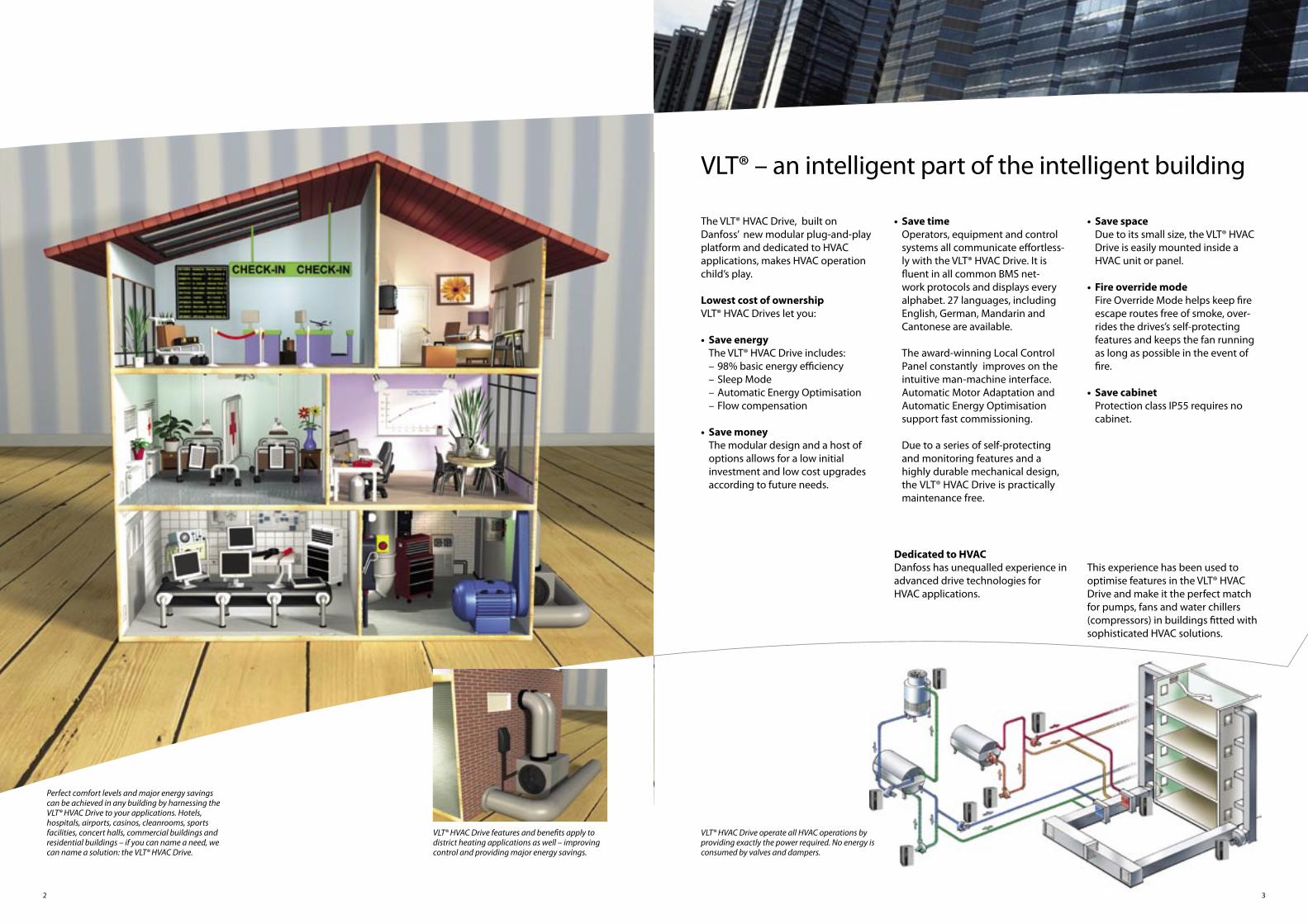
Perfect comfort levels and major energy savings can be achieved in any building by harnessing the VLT® HVAC Drive to your applications. Hotels, hospitals, airports, casinos, cleanrooms, sports facilities, concert halls, commercial buildings and residential buildings – if you can name a need, we can name a solution: the VLT® HVAC Drive.
VLT® HVAC Drive features and benefits apply to district heating applications as well – improving control and providing major energy savings.
• Save space Due to its small size, the VLT® HVAC Drive is easily mounted inside a HVAC unit or panel.
• Fire override mode Fire Override Mode helps keep fire escape routes free of smoke, over- rides the drives’s self-protecting features and keeps the fan running as long as possible in the event of fire.
• Save cabinet Protection class IP55 requires no cabinet.
VLT® HVAC Drive operate all HVAC operations by providing exactly the power required. No energy is consumed by valves and dampers.
Dedicated to HVACDanfoss has unequalled experience in advanced drive technologies for HVAC applications.
This experience has been used to optimise features in the VLT® HVAC Drive and make it the perfect match for pumps, fans and water chillers (compressors) in buildings fitted with sophisticated HVAC solutions.
54
Small investmentThe VLT® HVAC Drive is available in a range of versions, from a basic serial communication and I/O confi guration capable right up to a fully equipped and personalized drive, including all relevant HVAC I/O points and proto-cols. Delivered from factory. No extra assembly work on-site!
50° C ambient temperatureThe robust VLT® HVAC Drive is design- ed to work at maximum output in an ambient temperature up to 50° C.
Suitable for “slave” operationThe drive’s modular structure makes it suitable for “slave” operation mastered by BMS, PLC’s or DDCs.
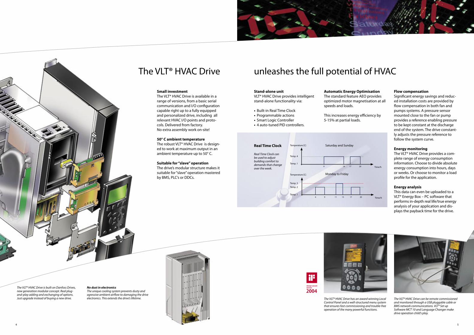
Stand-alone unitVLT® HVAC Drive provides intelligent stand-alone functionality via:
• Built-in Real Time Clock• Programmable actions• Smart Logic Controller • 4 auto-tuned PID controllers.
Automatic Energy OptimisationThe standard feature AEO provides optimized motor magnetisation at all speeds and loads.
This increases energy effi ciency by 5-15% at partial loads.
The VLT® HVAC Drive
The VLT® HVAC Drive has an award winning Local Control Panel and a well-structured menu system that ensures fast commissioning and trouble-free operation of the many powerful functions.
The VLT® HVAC Drive can be remote commissioned and monitored through a USB pluggable cable or BMS network communications. VLT® Set up Software MCT 10 and Language Changer make drive operation child’s play.
Flow compensationSignifi cant energy savings and reduc- ed installation costs are provided by fl ow compensation in both fan and pumps systems. A pressure sensor mounted close to the fan or pump provides a reference enabling pressure to be kept constant at the discharge end of the system. The drive constant-ly adjusts the pressure reference to follow the system curve.
Energy monitoring The VLT® HVAC Drive provides a com- plete range of energy consumption information. Choose to divide absolute energy consumption into hours, days or weeks. Or choose to monitor a load profi le for the application.
Energy analysisThis data can even be uploaded to a VLT® Energy Box – PC software that performs in-depth real life/true energy analysis of your application and dis- plays the payback time for the drive.
No dust in electronicsThe unique cooling system prevents dusty and agressive ambient airfl ow to damaging the drive electronics. This extends the drive’s lifetime.
The VLT® HVAC Drive is built on Danfoss Drives, new generation modular concept. Real plug-and-play adding and exchanging of options. Just upgrade instead of buying a new drive.
Saturday and Sunday
Monday to Friday
Temperature [C]
Temp. 4
Temp. 1
Temperature [C]
Temp. 3
Temp. 2
Temp. 1Time/h
Time/h 9 14 17 20
6 9 11 13 17 20
Real Time Clock can be used to adjust building comfort to demands that change over the week.
Real Time Clock
unleashes the full potential of HVAC

76
Comfort for fl ight personnel and passengersClean air and comfortable tempe-rature supports comfort and soothes frayed tempers. Air is moved, chilled, heated, humidifi ed and cleaned eff ectively consuming a minimum of energy and fi nancial resources. With VLT® HVAC Drive you get full control of pumps, fans and com-pressors.
Healthy Environment Patients thrive better breathing clean, conditioned air. Autotuning PID controllers ensure accurate control of airfl ow, maintaining a positive pressure in operating rooms to help maintain hygienic conditions and prevent cross contamination. VLT® HVAC Drive can maintain a negative pressure in isolation wards as well, ensuring a healthy environ-ment for all.
Where dust is criticalCleanroom facilities for the produc-tion of micro electronics like semi-conductor chips require special precautions. The VLT® HVAC Drive can meticulously control to maintain air quality and humidity levels under a variety of operating conditions, including continued operation during mains voltage fl uctuations.
Treated like a guestWhen walking into a hotel room you should experience a mild, fresh, clean smell and a feeling of comfort and relaxation. To provide this and at the same time go easy on energy and operating costs – choose a VLT® HVAC Drive.
The bottom lineThe initial cost of HVAC is almost negligible. Energy effi cient control of fans, pumps and compressors – day and night, during opening and closing hours – ensures maximum economy and low running costs. Let VLT® HVAC Drive impact your bottom line.
District heating/CoolingThe larger the system, the larger the savings that can be derived from the use of VLT® HVAC Drive. Precise con- trol of temperature, pressure and fl ow is done by speed control of pumps and fans – the best way to save natural resources. The larger system, the greater the power required – and VLT ® HVAC Drives goes all the way.
Hot businessLet VLT® HVAC Drive provide a reliable, comfortable environment for your offi ce staff . People should be able to work effi ciently without being distracted by sudden changes in temperature or humidity. Let a VLT® HVAC Drive quietly and eff ectively control the indoor climate, improve work effi ciency and help you keep cool in a hot business environment.
Best HVAC performance with VLT® HVAC Drive

98
Dedicated pump features in VLT® HVAC Drive
An operating pump will normally consume more power the faster it runs – according to a curve determined by the pump and application design.
VLT® HVAC Drive will detect situations where the pump runs fast but is not fully loaded – and thereby not consuming adequate power. This is the case when water circulation stops, the pump runs dry or when when pipes leak.
The VLT® HVAC Drive offers a vast number of pump-specific features developed in cooperation with OEMs, contractors and manufacturers around the world.
Pump Cascade ControllerThe Pump Cascade Controller is the most sophisticated controller on the market.
It distributes running hours evenly across all pumps, keeps wear and tear on individual pumps to a minimum and ensures that all pumps are in great shape.
Vital water supplyVital water supply can be assured in the event of leakage or a broken pipe. For example overload is prevented by reducing speed – and supply is secur- ed at lower flow.
Sleep Mode In Sleep Mode the drive detects situa- tions with low or no flow. Instead of continuous operation it boosts the system pressure and then stops to save energy. The drive starts automatically when the pressure falls below the lower set point.
Dry Pump Protection and End of Curve Dry Pump Protection and End of Curve relate to situations where the pump runs without creating the de- sired pressure – as when a well runs dry or a pipe leaks.
The drive sets off an alarm, shuts off the pump, or performs another programmed action.
No/low flow curve
Normal mode
Sleep Mode orRun Dry mode
Power
Max. pumppower
Min. pumppower
Min. pumpfrequency
Max. pumpfrequency
Frequency

Meticulous control of fans saves energy and keeps noise and draft at a minimum.
1110
Dedicated fan features
User-friendly, distributed intelligence and reduced power consumption are beneficial for fan applications.
Lower AHU costsThe VLT® HVAC Drive is fitted with a built-in Smart Logic Controller and 4 auto tune PID controllers and can control air handling functions with fans, valves, and dampers. The build- ing management’s DDC-’s are thereby released and valuable data points (DP) are saved.
Extends BMS capacityWhen integrated into the BMS net- work, all the HVAC Drive I/O points are available as remote I/O’s to extend BMS’s capacity. For example, room temperature sensors (Pt1000/Ni1000) can be directly connected.
Resonance Monitoring By pressing a few buttons on the Local Control Panel the drive can be set to avoid frequency bands at which connected fans create resonances in the ventilation system. This improves building comfort.
Intelligent AHU functionsThe VLT® HVAC Drive handles logical rules and input from sensors, real-time functionality, and time-related actions. This enables the HVAC Drive to control a wide range of functions, including:
• Weekend and working-day operations• Cascaded P-PI for temperature control• Multi-zone pressure control• Flow balancing between fresh and outlet air
Belt Monitoring From the relation between current and speed, the VLT® HVAC Drive is able to reliably recognize a broken belt. Lack of air flow detected immediately, first cost and down-time is reduced.
Fire Override Mode In Fire Override Mode the VLT® HVAC Drive will not react to control signals, warnings or alarms. It will continue its reliable operation as long as possible and run until it eventually selfdestruct.
Stairwell PressurizationIn the event of fire, the VLT® HVAC Drive can maintain a higher level of air pressure in stairwells than in other parts of the building and ensure that fire escapes remain free of smoke.
Speed
Differential pressure
Easy to opendoors
Freshair in

VLT® HVAC drive allows you to rethink your compressor operation.
1312
The VLT® HVAC Drive has been design- ed to offer flexible, intelligent control of scroll, screw and centrifugal com- pressors, making it even easier to optimize cooling capacity with con- stant temperature and pressure levels for water chillers, and other typical compressor applications in HVAC.
Replace a cascade with a single compressorThe VLT® HVAC Drive provides the same level of flexibility with one large compressor instead of a cascade of 2 or 3 smaller compressors.The HVAC Drive operates all compressors at a far more re-fined range of speeds than normal – even above nominal speed – meaning that one large compressor is now enough.
Dedicated compressor features
Flexible compressor mode operation even above nominal speed and high break away torque for start-ups allow for better control and major savings.
Set point in temperature The VLT® HVAC Drive calculates the actual room temperature from the pressure in the cooling media and refines compressor operation accord-ingly – without the need for addition-al software, sensors or controllers.
This calculation is also applicable to the set point as well, so the desired temperature is set via the Local Control Panel – and not a pressure value.
Fewer starts and stopsA maximum number of start/stop cycles within a given period of time can be set via the Local Control Panel. Since start-up is the most critical part of compressor operation (all parts of the unit are under mechanical stress before the system is sufficiently lubric- ated) this extends compressor lifetime.
Quick start-upTo extend life even further, the VLT® HVAC Drive opens a bypass valve and lets the compresser start quickly without load.
The VLT® HVAC Drive provides 130% break away torque and can give 110% torque for 60 seconds in normal ope- ration. This torque demand would normally require larger and more ex- pensive drives.
1514
Proven HVAC experience
Tropical Islands Resort near Berlin, GermanyA steady 25° C air temperature, 31° C water temperature, no rain, and a pleasant 40% to 60% humidity for the resort’s tropical plants. Everyone’s idea of perfect weather! All this is possible with a first class climate and water control system driven by VLT® HVAC Drives.
Opera House in Sydney, AustraliaThe Sydney Opera House is one of the architectural wonders of the world, and perhaps the best known building of the 20th century. In 2001, the NSW Government provided $69 million for several projects to improve the facilities and environment for performing arts companies, patrons and visitors. Danfoss provided the drives.
Shanghai General Motors, ChinaShanghai General Motors Co Ltd. is a 50-50% joint venture between General Motors and the Shanghai Automotive Industry Corporation Group (SAIC).Shanghai GM has an annual production capacity of 200,000 vehicles. Danfoss provides the VLT® HVAC drives to maintain the production environment.
Grand Hyatt, DubaiSet within a lush oasis of 37 acres of landscaped gardens, the Grand Hyatt Dubai is an outstanding combination of resort facilities, luxury hotel guest rooms and suites, residential apartments and one of the most advanced conference centers in the Middle East. Danfoss provided the VLT® HVAC Drives.
Guangzhou Baiyun Pharmaceutical Factory, ChinaGuangzhou Baiyunshan Pharmaceutical Manufacturer was established in 1993 andis a listed company with a good reputation in the pharmaceutical field in China. Its share value is around RMB 374 million and sales turnover in 2004 was RMB 2,5 billion.Danfoss provided the drives.
Torre Mayor, Mexico CityWith its 55 floors and a height of 225 m the Torre Mayor is the highest building in Latin America. Danfoss drives control the heatingand ventilation.
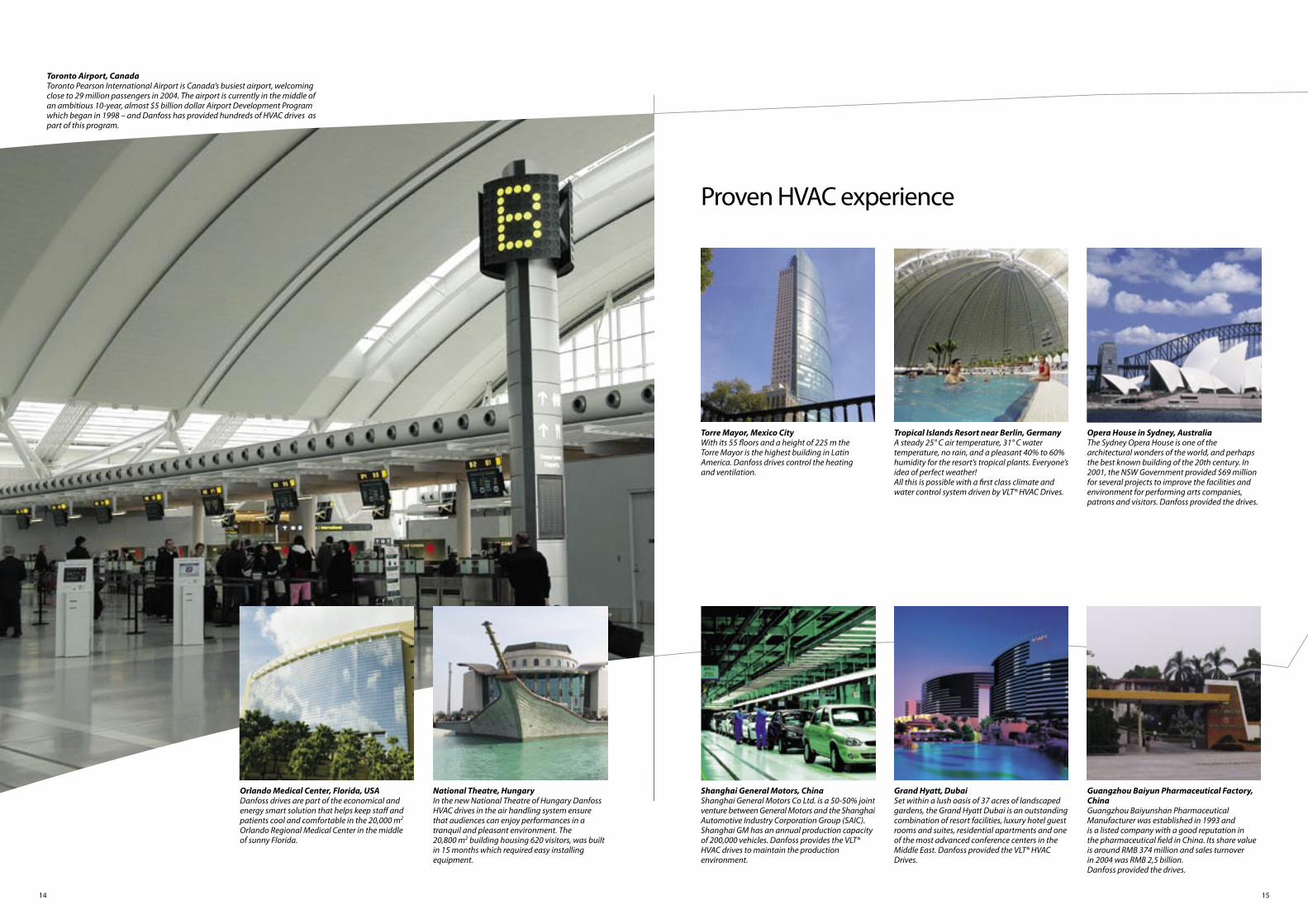
Toronto Airport, CanadaToronto Pearson International Airport is Canada’s busiest airport, welcoming close to 29 million passengers in 2004. The airport is currently in the middle of an ambitious 10-year, almost $5 billion dollar Airport Development Program which began in 1998 – and Danfoss has provided hundreds of HVAC drives as part of this program.
Orlando Medical Center, Florida, USADanfoss drives are part of the economical and energy smart solution that helps keep staff and patients cool and comfortable in the 20,000 m2 Orlando Regional Medical Center in the middle of sunny Florida.
National Theatre, HungaryIn the new National Theatre of Hungary Danfoss HVAC drives in the air handling system ensure that audiences can enjoy performances in a tranquil and pleasant environment. The 20,800 m2 building housing 620 visitors, was built in 15 months which required easy installing equipment.
1716
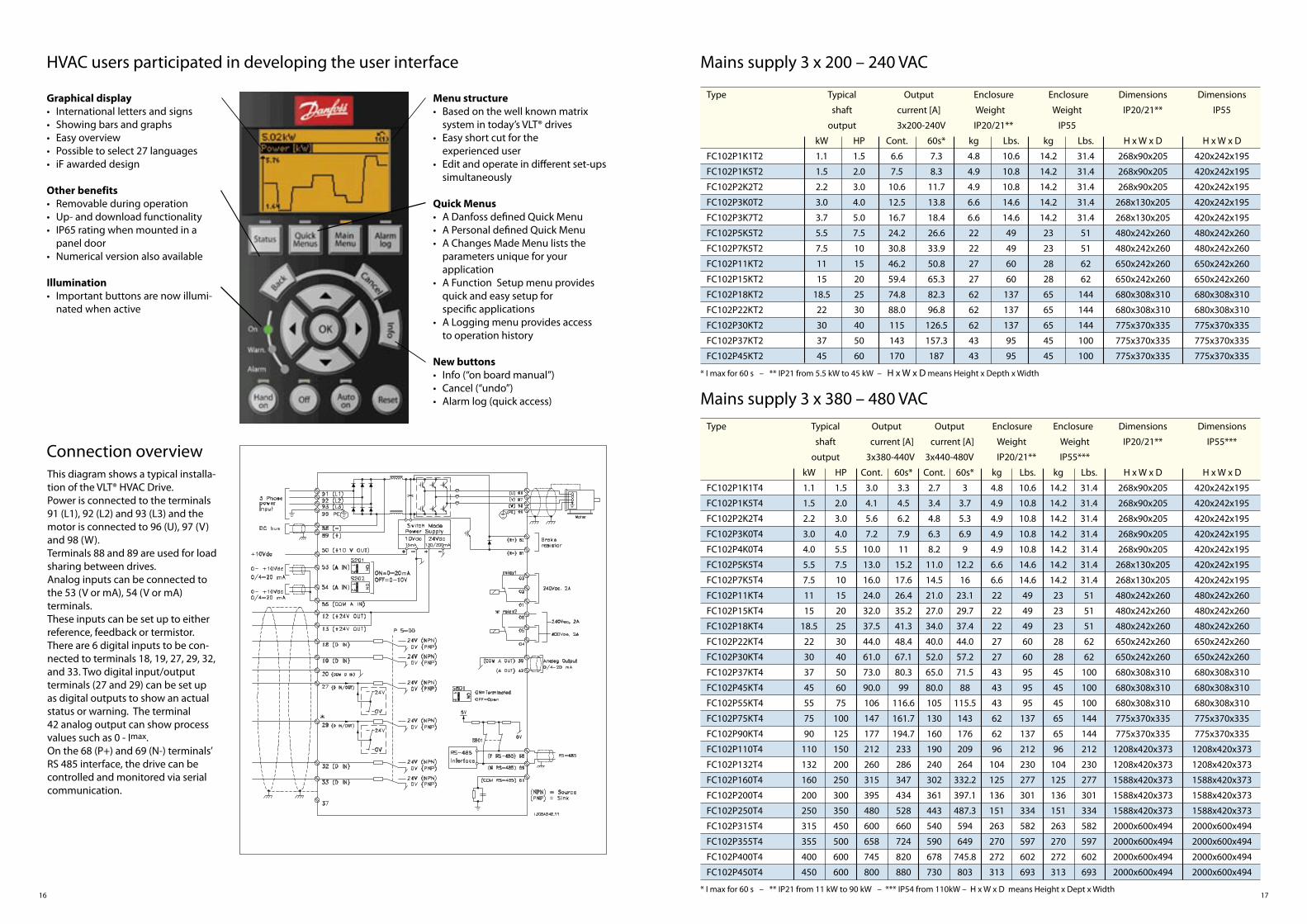
HVAC users participated in developing the user interface
Graphical display• International letters and signs• Showing bars and graphs• Easy overview• Possible to select 27 languages• iF awarded design
Other benefits• Removable during operation• Up- and download functionality• IP65 rating when mounted in a panel door• Numerical version also available
Illumination• Important buttons are now illumi-
nated when active
Menu structure• Based on the well known matrix system in today’s VLT® drives• Easy short cut for the experienced user• Edit and operate in different set-ups simultaneously
Quick Menus• A Danfoss defined Quick Menu• A Personal defined Quick Menu• A Changes Made Menu lists the parameters unique for your application• A Function Setup menu provides quick and easy setup for specific applications• A Logging menu provides access to operation history
New buttons• Info (“on board manual”)• Cancel (“undo”)• Alarm log (quick access)
Connection overviewThis diagram shows a typical installa-tion of the VLT® HVAC Drive.Power is connected to the terminals 91 (L1), 92 (L2) and 93 (L3) and the motor is connected to 96 (U), 97 (V) and 98 (W). Terminals 88 and 89 are used for load sharing between drives.Analog inputs can be connected to the 53 (V or mA), 54 (V or mA) terminals.These inputs can be set up to either reference, feedback or termistor. There are 6 digital inputs to be con-nected to terminals 18, 19, 27, 29, 32, and 33. Two digital input/output terminals (27 and 29) can be set up as digital outputs to show an actual status or warning. The terminal 42 analog output can show process values such as 0 - Imax. On the 68 (P+) and 69 (N-) terminals’RS 485 interface, the drive can be controlled and monitored via serial communication.
Mains supply 3 x 200 – 240 VAC
Type Typical Output Enclosure Enclosure Dimensions Dimensions
shaft current [A] Weight Weight IP20/21** IP55
output 3x200-240V IP20/21** IP55
kW HP Cont. 60s* kg Lbs. kg Lbs. H x W x D H x W x D
FC102P1K1T2 1.1 1.5 6.6 7.3 4.8 10.6 14.2 31.4 268x90x205 420x242x195
FC102P1K5T2 1.5 2.0 7.5 8.3 4.9 10.8 14.2 31.4 268x90x205 420x242x195
FC102P2K2T2 2.2 3.0 10.6 11.7 4.9 10.8 14.2 31.4 268x90x205 420x242x195
FC102P3K0T2 3.0 4.0 12.5 13.8 6.6 14.6 14.2 31.4 268x130x205 420x242x195
FC102P3K7T2 3.7 5.0 16.7 18.4 6.6 14.6 14.2 31.4 268x130x205 420x242x195
FC102P5K5T2 5.5 7.5 24.2 26.6 22 49 23 51 480x242x260 480x242x260
FC102P7K5T2 7.5 10 30.8 33.9 22 49 23 51 480x242x260 480x242x260
FC102P11KT2 11 15 46.2 50.8 27 60 28 62 650x242x260 650x242x260
FC102P15KT2 15 20 59.4 65.3 27 60 28 62 650x242x260 650x242x260
FC102P18KT2 18.5 25 74.8 82.3 62 137 65 144 680x308x310 680x308x310
FC102P22KT2 22 30 88.0 96.8 62 137 65 144 680x308x310 680x308x310
FC102P30KT2 30 40 115 126.5 62 137 65 144 775x370x335 775x370x335
FC102P37KT2 37 50 143 157.3 43 95 45 100 775x370x335 775x370x335
FC102P45KT2 45 60 170 187 43 95 45 100 775x370x335 775x370x335
Mains supply 3 x 380 – 480 VAC
Type Typical Output Output Enclosure Enclosure Dimensions Dimensions
shaft current [A] current [A] Weight Weight IP20/21** IP55***
output 3x380-440V 3x440-480V IP20/21** IP55***
kW HP Cont. 60s* Cont. 60s* kg Lbs. kg Lbs. H x W x D H x W x D
FC102P1K1T4 1.1 1.5 3.0 3.3 2.7 3 4.8 10.6 14.2 31.4 268x90x205 420x242x195
FC102P1K5T4 1.5 2.0 4.1 4.5 3.4 3.7 4.9 10.8 14.2 31.4 268x90x205 420x242x195
FC102P2K2T4 2.2 3.0 5.6 6.2 4.8 5.3 4.9 10.8 14.2 31.4 268x90x205 420x242x195
FC102P3K0T4 3.0 4.0 7.2 7.9 6.3 6.9 4.9 10.8 14.2 31.4 268x90x205 420x242x195
FC102P4K0T4 4.0 5.5 10.0 11 8.2 9 4.9 10.8 14.2 31.4 268x90x205 420x242x195
FC102P5K5T4 5.5 7.5 13.0 15.2 11.0 12.2 6.6 14.6 14.2 31.4 268x130x205 420x242x195
FC102P7K5T4 7.5 10 16.0 17.6 14.5 16 6.6 14.6 14.2 31.4 268x130x205 420x242x195
FC102P11KT4 11 15 24.0 26.4 21.0 23.1 22 49 23 51 480x242x260 480x242x260
FC102P15KT4 15 20 32.0 35.2 27.0 29.7 22 49 23 51 480x242x260 480x242x260
FC102P18KT4 18.5 25 37.5 41.3 34.0 37.4 22 49 23 51 480x242x260 480x242x260
FC102P22KT4 22 30 44.0 48.4 40.0 44.0 27 60 28 62 650x242x260 650x242x260
FC102P30KT4 30 40 61.0 67.1 52.0 57.2 27 60 28 62 650x242x260 650x242x260
FC102P37KT4 37 50 73.0 80.3 65.0 71.5 43 95 45 100 680x308x310 680x308x310
FC102P45KT4 45 60 90.0 99 80.0 88 43 95 45 100 680x308x310 680x308x310
FC102P55KT4 55 75 106 116.6 105 115.5 43 95 45 100 680x308x310 680x308x310
FC102P75KT4 75 100 147 161.7 130 143 62 137 65 144 775x370x335 775x370x335
FC102P90KT4 90 125 177 194.7 160 176 62 137 65 144 775x370x335 775x370x335
FC102P110T4 110 150 212 233 190 209 96 212 96 212 1208x420x373 1208x420x373
FC102P132T4 132 200 260 286 240 264 104 230 104 230 1208x420x373 1208x420x373
FC102P160T4 160 250 315 347 302 332.2 125 277 125 277 1588x420x373 1588x420x373
FC102P200T4 200 300 395 434 361 397.1 136 301 136 301 1588x420x373 1588x420x373
FC102P250T4 250 350 480 528 443 487.3 151 334 151 334 1588x420x373 1588x420x373
FC102P315T4 315 450 600 660 540 594 263 582 263 582 2000x600x494 2000x600x494
FC102P355T4 355 500 658 724 590 649 270 597 270 597 2000x600x494 2000x600x494
FC102P400T4 400 600 745 820 678 745.8 272 602 272 602 2000x600x494 2000x600x494
FC102P450T4 450 600 800 880 730 803 313 693 313 693 2000x600x494 2000x600x494
* I max for 60 s – ** IP21 from 5.5 kW to 45 kW – H x W x D means Height x Depth x Width
* I max for 60 s – ** IP21 from 11 kW to 90 kW – *** IP54 from 110kW – H x W x D means Height x Dept x Width
1918
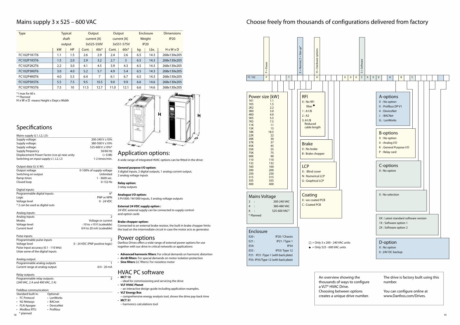
Choose freely from thousands of configurations delivered from factory
An overview showing the thousands of ways to configure a VLT® HVAC Drive. Choosing between options creates a unique drive number.
The drive is factory built using this number.
You can configure online at www.Danfoss.com/Drives.
Power size [kW]1K11K52K23K04K05K57K511K15K18K22K30K37K45K55K75K90K110132160200250315355400
Mains Voltage2 : 200-240 VAC
4 : 380-480 VAC
6 : 525-600 VAC*
* Planned
EnclosureE20 : IP20 / Chassis
E21 : IP21 / Type 1
E54: IP54
E55 : IP55/ Type 12
P21: IP21 /Type 1 (with back plate)
P55: IP55/Type 12 (with back plate)
RFIX : No RFI
filter
1 : A1/B
2 : A2
3: A1/B Reduced cable length
BrakeX : No brake
B : Brake chopper
LCPX : Blind cover
N : Numerical LCP
G : Graphical LCP
CoatingX : wo coated PCB
C : Coated PCB
A-optionsX : No option
0 : Profibus DP V1
4 : DeviceNet
J : BACNet
G : LonWorks
B-optionsX : No option
0 : Analog I/O
K : General Purpose I/O
P : Relay card
C-optionsX : No option
X : No selection
XX : Latest standard software version
1X : Software option 1
2X : Software option 2
D-optionX : No option
0 : 24V DC backup
= Only 3 x 200 - 240 VAC units
= Only 525 - 600 VAC units
P =
Pow
er
E =
Nor
mal
; Z =
Siz
e up
*
H =
Har
dwar
e op
tions
S =
Sof
twar
e
FC 102 P T H S BX X X X X X A C
Mains supply 3 x 525 – 600 VAC
* I max for 60 s** PlannedH x W x D means Height x Dept x Width
Type Typical Output Output Enclosure Dimensions
shaft current [A] current [A] Weight IP20
output 3x525-550V 3x551-575V IP20
kW HP Cont. 60s* Cont. 60s* kg Lbs. H x W x D
FC102P1K1T6 1.1 1.5 2.6 2.9 2.4 2.6 6.5 14.3 268x130x205
FC102P1K5T6 1.5 2.0 2.9 3.2 2.7 3 6.5 14.3 268x130x205
FC102P2K2T6 2.2 3.0 4.1 4.5 3.9 4.3 6.5 14.3 268x130x205
FC102P3K0T6 3.0 4.0 5.2 5.7 4.9 5.4 6.5 14.3 268x130x205
FC102P4K0T6 4.0 5.5 6.4 7 6.1 6.7 6.5 14.3 268x130x205
FC102P5K5T6 5.5 7.5 9.5 10.5 9.0 9.9 6.6 14.6 268x130x205
FC102P7K5T6 7.5 10 11.5 12.7 11.0 12.1 6.6 14.6 268x130x205
Mains supply (L1, L2, L3): Supply voltage: 200-240 V ±10%Supply voltage: 380-500 V ±10%Supply voltage: 525-600 V ±10%*Supply frequency 50/60 HzDisplacement Power Factor (cos φ) near unity (> 0.98)Switching on input supply L1, L2, L3 1-2 times/min.
Output data (U, V, W): Output voltage 0-100% of supply voltageSwitching on output UnlimitedRamp times 1 - 3600 sec.Closed loop 0-132 Hz
Digital inputs: Programmable digital inputs: 6*Logic PNP or NPNVoltage level 0 - 24 VDC* 2 can be used as digital outs
Analog inputs: Analog inputs 2Modes Voltage or currentVoltage level: -10 to +10 V (scaleable)Current level 0/4 to 20 mA (scaleable)
Pulse inputs: Programmable pulse inputs 2Voltage level 0 - 24 VDC (PNP positive logic)Pulse input accuracy (0.1 - 110 kHz) Utize some of the digital inputs
Analog output: Programmable analog outputs 1Current range at analog output 0/4 - 20 mA
Relay outputs: Programmable relay outputs: 2(240 VAC, 2 A and 400 VAC, 2 A)
Fieldbus communication: Standard built in: Optional:• FC Protocol • LonWorks• N2 Metasys • BACnet• FLN Apogee • DeviceNet• Modbus RTU • Profibus * planned
A wide range of integrated HVAC options can be fitted in the drive:
General purpose I/O option: 3 digital inputs, 2 digital outputs, 1 analog current output, 2 analog voltage inputs
Relay option: 3 relay outputs
Analogue I/O option: 3 Pt1000 / Ni1000 inputs, 3 analog voltage outputs
External 24 VDC supply option :24 VDC external supply can be connected to supply control- and option cards
Brake chopper option:Connected to an external brake resistor, the built in brake chopper limits the load on the intermediate circuit in case the motor acts as generator.
Power optionsDanfoss Drives offers a wide range of external power options for use together with our drive in critical networks or applications:
• Advanced harmonic filters: For critical demands on harmonic distortion • dv/dt filters: For special demands on motor isolation protection• Sine filters (LC filters): For noiseless motor
HVAC PC software• MCT 10 – ideal for commissioning and servicing the drive• VLT HVAC Planet – an interactive design guide including application examples.• VLT Energy Box – comprehensive energy analysis tool, shows the drive pay-back time• MCT 31 – harmonics calculations tool
Specifications
Application options:
H
D
W
H
W
D
1.11.52.23.04.05.57.51115
18.522303745557590
110132160200250315355400

DKDD.PB.100.A1.02 VLT® is a trademark of Danfoss A/S www.simpatico.dk.2005.12
Danfoss Drives, Ulsnaes 1, DK-6300 Graasten. Denmark • Telephone: +45 74 88 22 22 • Fax: +45 74 65 25 80www.Danfoss.com/Drives • E-mail: [email protected]
What VLT® is all about
Dedicated to drivesDedication has been a key word since 1968, when Danfoss introduced the world’s first mass produced variable speed drive for AC motors – and named it VLT®.Two thousand employees develop, manufacture, sell and service drives and softstarters in more than one hundred countries – and nothing but drives and softstarters.
Intelligent and innovative Developers at Danfoss Drives have fully adopted modular principles in development as well as design, pro- duction and configuration. Tomorrow’s features are developed in parallel using dedicated technology platforms. This allows the develop-ment of each element to take in parallel, at the same time reducing time to market and ensuring that customers always enjoy the benefits of the latest features.
Depend on the expertsWe take responsibility for every element in our products. The fact that we develop and produce our own features, hardware, software, power modules, printed circuit boards, and accessories is your guarantee for reliable products.
Danfoss Drives is the world leader among dedicated drives providers – and still gaining market shares.
Local backup – globallyVLT® motor controls are operating in applications all over the world and Danfoss Drives, experts are ready to support our customers with applica-tion advice and service wherever they may be.
Danfoss Drives experts only ever stop when the customer’s drive problems are solved.