wall box solutionsindoor/outdoor fiber terminals, … · indoor/outdoor fiber terminals, cabinets...
TRANSCRIPT

1st Edition
Wall Box SolutionsIndoor/Outdoor Fiber Terminals, Cabinets and Boxes for FTTx

6/
11
•
1
09
75
6A
E
Wal
l B
ox
Solu
tio
ns
3 w w w . t e . c o m / a d c • + 1 - 9 5 2 - 9 3 8 - 8 0 8 0 • 1 - 8 0 0 - 3 6 6 - 3 8 9 1
Introduction ..................................................................................................... 5
Products-at-a-Glance ....................................................................................6-8
Rapid Fiber SystemMini Rapid Distribution Terminal (RDT) ...........................................................9Rapid Collector Enclosure ............................................................................10Rapid Distribution Terminal .....................................................................11-12
Small Outdoor Fiber Distribution Terminal (oFDT) ................................13-14
Large Outdoor Fiber Distribution Terminals (oFDT) ..............................15-16
Indoor Fiber Distribution Terminals (iFDT) .............................................17-19
Wall Splice Cabinets ...................................................................................... 20
Fiber Demarcation Cabinets (FDC)NEMA FDC with Pigtails ...............................................................................23NEMA FDC Preterminated with Multifiber Cable ..........................................23
FL1 Fiber Wall Mount BoxesIndoor Fiber Wall Mount Boxes ...............................................................24-256pack Adapter Packs ..............................................................................26-28
Fiber Splitter Boxes (FSB) ........................................................................29-31
AccessoriesFiber Connector/Adapter Cleaning Kit .....................................................32-33Protective Tubing Cutting Tool .....................................................................34Grounding/Moisture Blocking Kits ................................................................34Splice Protector Sleeves ................................................................................35Wrench Keys................................................................................................35
Wall Box SolutionsTable of Contents
For additional wall box solutions, including TE’s FibrBoss and FIST termination boxes, visit www.te.com/wallboxes. Or, contact customer service at (888) 557-8901 and request a data sheet:
Description Literature No. Description Literature No. Description Literature No.
FibrBoss PB06-S F728 FibrBoss PB06B F750 FibrBoss CB-04 F352
FibrBoss CB12 F351 FibrBoss CB24 F338 FibrBoss CB48 F367
FibrBoss DB36 F373 FIST-CTB2-4 TC 569/DS/6

6/
11
•
1
09
75
6A
E
Wal
l B
ox
Solu
tio
ns
5 w w w . t e . c o m / a d c • + 1 - 9 5 2 - 9 3 8 - 8 0 8 0 • 1 - 8 0 0 - 3 6 6 - 3 8 9 1
TE Connectivity (TE): The Connectivity Leader in Fiber Wall Box Solutions
No matter what your network requirements are, TE has a complete portfolio of wall box solutions available to meet your fiber connectivity needs. In today’s competitive marketplace, every subscriber counts, which demands service providers to be more strategic in their network plans and fiber deployments. To satisfy customers’ bandwidth requirements, service providers need to build their networks smarter, faster and more efficiently. At the same time, increased competition in the marketplace is pressuring providers to reduce unnecessary capital and operating expenses wherever possible. These challenges can have a major impact on service providers’ bottom line. Ultimately, choosing network equipment that addresses flexibility and future capacity is vital to building and sustaining a cost-effective and profitable network. TE's wall box solutions help to address these challenges, and offer customers’ unrivaled quality, performance and reliability for the multifaceted needs of tomorrow’s networks.
TE Wall Box Portfolio
TE wall boxes are designed for use in both in-building and outside plant environments—from the CO/Head End to the customer premises locations.
• Offer an unrivaled breadth of low to high density solutions with superior cable management
• “Right sized” enclosures meet space requirements for a variety of environments
• Proven reliability in fiber networks
• Modular, “build as you grow” flexibility
• Promotes fast service turn ups
Cable Management
The management of the fiber cables has a direct impact on network reliability, performance and cost. TE’s wall box solutions incorporate the four elements of a successful cable management system:
• Integrated bend radius protection
• Clear, intuitive cable routing paths
• Easy connector and cable access
• Physical protection of fiber
Performance
TE’s wall box solutions are designed to perform in the most rigorous customer applications and in a variety of fiber environments.
• Created for longevity and low life-cycle cost
• Ensure fast and easy installation
• Engineered for easy expansion and for cost-effective upgrades
• Withstands harsh inside and outside environmental conditions
Innovation
Many TE wall box solutions incorporate the latest in cutting-edge technology, helping to deliver unmatched savings in installation time, and labor costs and performance in all fiber networks.
• RapidReel™ fiber system allows the cable to payoff directly from the stubbed enclosure assembly—speeds installation and labor requirements
• Reduced bend radius fiber eliminates attenuation caused from macro bends; and allows for tighter slack storage spools and promotes the use of smaller enclosure
• Low-loss MPO connectors promote the use of easier handing and routing of cables
• Unique swing-frame design allows easy technician access to connectors and fibers for MACS
• Plug-and-play technology reduces splice labor requirements and speeds service turn ups
Quality
TE strives to exceed customer expectations and is committed to delivering the highest quality products throughout the world. TE accomplishes this through continual improvement in customer satisfaction, supplier relationships and our business management system. ISO 9001 standards and statistical process controls help to keep TE's wall box equipment within strict specifications—serving the life of the product.
Wall Box SolutionsIntroduction
6/
11
•
1
09
75
6A
E
Wal
l B
ox
Solu
tio
ns
6 w w w . t e . c o m / a d c • + 1 - 9 5 2 - 9 3 8 - 8 0 8 0 • 1 - 8 0 0 - 3 6 6 - 3 8 9 1
TE Solutions for Fiber Connectivity Features and Benefits Application
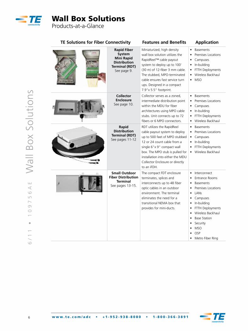
Rapid Fiber System
Mini Rapid Distribution
Terminal (RDT)See page 9.
Miniaturized, high density
wall box solution utilizes the
RapidReel™ cable payout
system to deploy up to 100'
(30 m) of 12-fiber 3 mm cable.
The stubbed, MPO-terminated
cable ensures fast service turn
ups. Designed in a compact
7.9”x 5.5” footprint.
• Basements
• Premises Locations
• Campuses
• In-building
• FTTH Deployments
• Wireless Backhaul
• MSO
Collector Enclosure
See page 10.
Collector serves as a zoned,
intermediate distribution point
within the MDU for fiber
architectures using MPO cable
stubs. Unit connects up to 72
fibers or 6 MPO connectors.
• Basements
• Premises Locations
• Campuses
• In-building
• FTTH Deployments
• Wireless Backhaul
Rapid Distribution
Terminal (RDT) See pages 11-12
RDT utilizes the RapidReel
cable payout system to deploy
up to 500 feet of MPO stubbed
12 or 24 count cable from a
single 6"x 9" compact wall
box. The MPO stub is pulled for
installation into either the MDU
Collector Enclosure or directly
to an iFDH.
• Basements
• Premises Locations
• Campuses
• In-building
• FTTH Deployments
• Wireless Backhaul
Small Outdoor Fiber Distribution
Terminal See pages 13-15.
The compact FDT enclosure
terminates, splices and
interconnects up to 48 fiber
optic cables in an outdoor
environment. The terminal
eliminates the need for a
transitional NEMA box that
provides for mini-ducts.
• Interconnect
• Entrance Rooms
• Basements
• Premises Locations
• LANs
• Campuses
• In-building
• FTTH Deployments
• Wireless Backhaul
• Base Station
• Security
• MSO
• OSP
• Metro Fiber Ring
Wall Box SolutionsProducts-at-a-Glance
6/
11
•
1
09
75
6A
E
Wal
l B
ox
Solu
tio
ns
7 w w w . t e . c o m / a d c • + 1 - 9 5 2 - 9 3 8 - 8 0 8 0 • 1 - 8 0 0 - 3 6 6 - 3 8 9 1
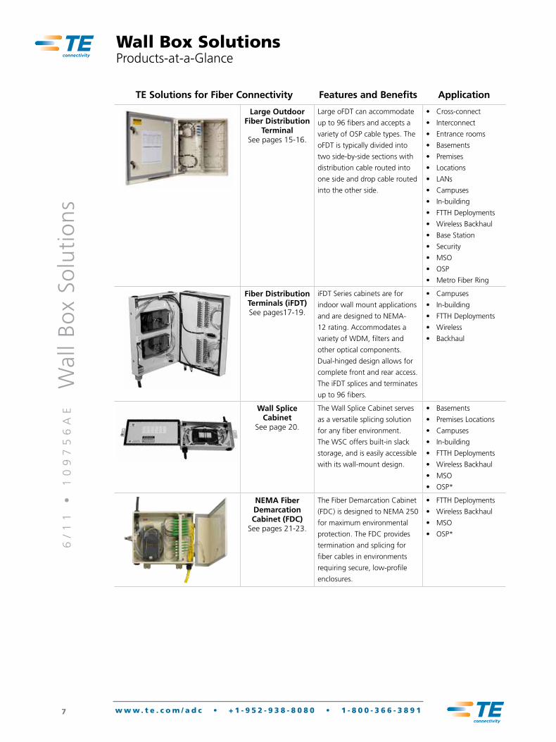
TE Solutions for Fiber Connectivity Features and Benefits Application
Large Outdoor Fiber Distribution
Terminal See pages 15-16.
Large oFDT can accommodate
up to 96 fibers and accepts a
variety of OSP cable types. The
oFDT is typically divided into
two side-by-side sections with
distribution cable routed into
one side and drop cable routed
into the other side.
• Cross-connect
• Interconnect
• Entrance rooms
• Basements
• Premises
• Locations
• LANs
• Campuses
• In-building
• FTTH Deployments
• Wireless Backhaul
• Base Station
• Security
• MSO
• OSP
• Metro Fiber Ring
Fiber Distribution Terminals (iFDT) See pages17-19.
iFDT Series cabinets are for
indoor wall mount applications
and are designed to NEMA-
12 rating. Accommodates a
variety of WDM, filters and
other optical components.
Dual-hinged design allows for
complete front and rear access.
The iFDT splices and terminates
up to 96 fibers.
• Campuses
• In-building
• FTTH Deployments
• Wireless
• Backhaul
Wall Splice Cabinet
See page 20.
The Wall Splice Cabinet serves
as a versatile splicing solution
for any fiber environment.
The WSC offers built-in slack
storage, and is easily accessible
with its wall-mount design.
• Basements
• Premises Locations
• Campuses
• In-building
• FTTH Deployments
• Wireless Backhaul
• MSO
• OSP*
NEMA Fiber Demarcation Cabinet (FDC)
See pages 21-23.
The Fiber Demarcation Cabinet
(FDC) is designed to NEMA 250
for maximum environmental
protection. The FDC provides
termination and splicing for
fiber cables in environments
requiring secure, low-profile
enclosures.
• FTTH Deployments
• Wireless Backhaul
• MSO
• OSP*
Wall Box SolutionsProducts-at-a-Glance
6/
11
•
1
09
75
6A
E
Wal
l B
ox
Solu
tio
ns
8 w w w . t e . c o m / a d c • + 1 - 9 5 2 - 9 3 8 - 8 0 8 0 • 1 - 8 0 0 - 3 6 6 - 3 8 9 1
TE Solutions for Fiber Connectivity Features and Benefits Application
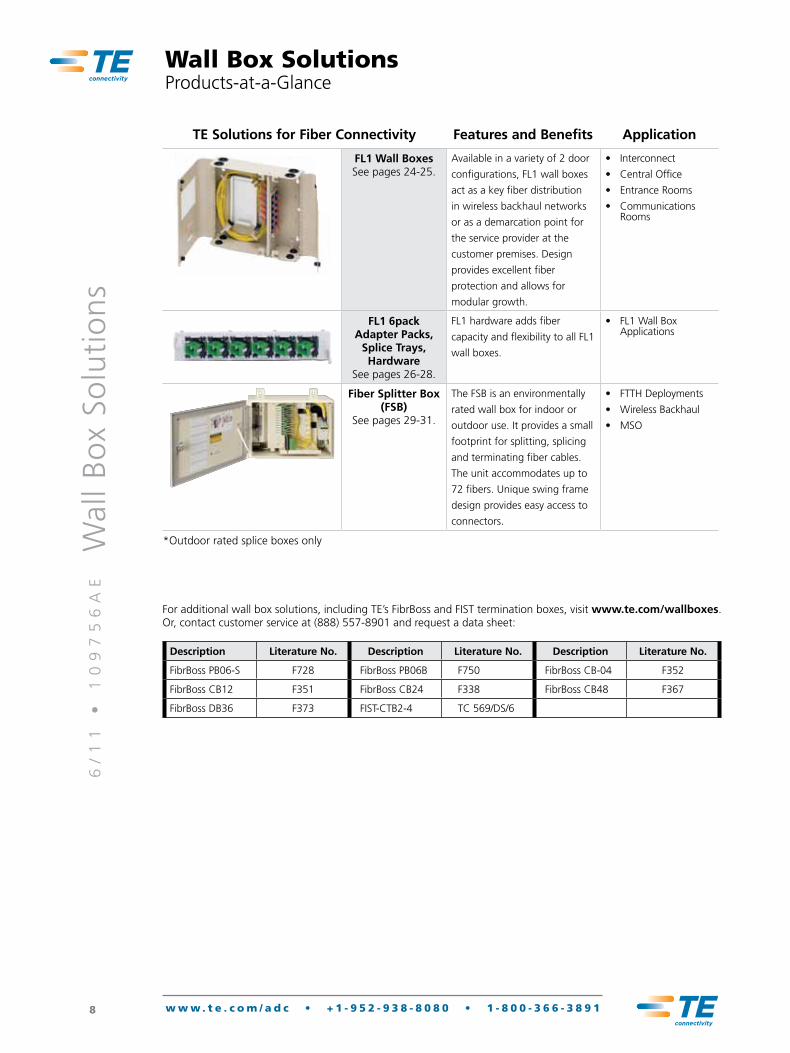
FL1 Wall Boxes See pages 24-25.
Available in a variety of 2 door
configurations, FL1 wall boxes
act as a key fiber distribution
in wireless backhaul networks
or as a demarcation point for
the service provider at the
customer premises. Design
provides excellent fiber
protection and allows for
modular growth.
• Interconnect
• Central Office
• Entrance Rooms
• Communications Rooms
FL1 6pack Adapter Packs,
Splice Trays, Hardware
See pages 26-28.
FL1 hardware adds fiber
capacity and flexibility to all FL1
wall boxes.
• FL1 Wall Box Applications
Fiber Splitter Box (FSB)
See pages 29-31.
The FSB is an environmentally
rated wall box for indoor or
outdoor use. It provides a small
footprint for splitting, splicing
and terminating fiber cables.
The unit accommodates up to
72 fibers. Unique swing frame
design provides easy access to
connectors.
• FTTH Deployments
• Wireless Backhaul
• MSO
*Outdoor rated splice boxes only
Wall Box SolutionsProducts-at-a-Glance
For additional wall box solutions, including TE’s FibrBoss and FIST termination boxes, visit www.te.com/wallboxes. Or, contact customer service at (888) 557-8901 and request a data sheet:
Description Literature No. Description Literature No. Description Literature No.
FibrBoss PB06-S F728 FibrBoss PB06B F750 FibrBoss CB-04 F352
FibrBoss CB12 F351 FibrBoss CB24 F338 FibrBoss CB48 F367
FibrBoss DB36 F373 FIST-CTB2-4 TC 569/DS/6
Data Sheet
tyco electronics Corporation, a te Connectivity Ltd. Company. all Rights Reserved.
312554ae/109512ae/109756ae 3/12 Original/Revision/Revision © 2012
te Connectivity, te connectivity (logo), tyco electronics, te (logo), aDC, Rapid and RapidReel are trademarks of the te Connectivity Ltd. family of companies and its licensors. While te Connectivity has made every reasonable effort to ensure the accuracy of the information in this document, te Connectivity does not guarantee that it is error-free, nor does te Connectivity make any other representation, warranty or guarantee that the information is accurate, correct, reliable or current. te Connectivity reserves the right to make any adjustments to the information contained herein at any time without notice. te Connectivity expressly disclaims all implied warranties regarding the information contained herein, including, but not limited to, any implied warranties of merchantability or fitness for a particular purpose. the dimensions in this document are for reference purposes only and are subject to change without notice. Specifications are subject to change without notice. Consult te Connectivity for the latest dimensions and design specifications.
tyco electronics and aDC are now TE Connectivity
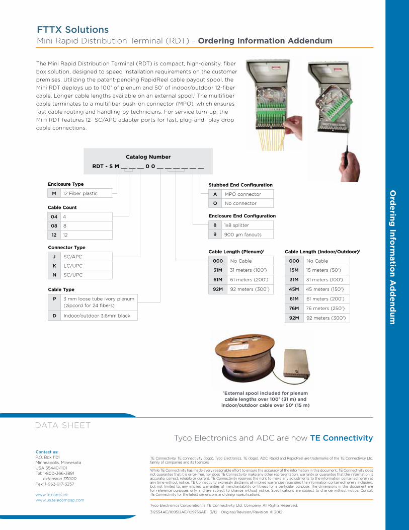
FTTX SolutionsMini Rapid Distribution terminal (RDt) - Ordering Information Addendum
Enclosure Type
M 12 Fiber plastic
Catalog Number
RDT - S M __ __ __ 0 0 __ __ __ __ __ __
Enclosure End Configuration
8 1x8 splitter
9 900 µm fanouts
Cable Count
04 4
08 8
12 12
Connector Type
J SC/aPC
K LC/UPC
N SC/UPC
Cable Type
P 3 mm loose tube ivory plenum (zipcord for 24 fibers)
D Indoor/outdoor 3.6mm black
Stubbed End Configuration
A MPO connector
O No connector
Cable Length (Plenum)1
000 No Cable
31M 31 meters (100')
61M 61 meters (200')
92M 92 meters (300')
Cable Length (Indoor/Outdoor)1
000 No Cable
15M 15 meters (50')
31M 31 meters (100')
45M 45 meters (150')
61M 61 meters (200')
76M 76 meters (250')
92M 92 meters (300')
1External spool included for plenum cable lengths over 100' (31 m) and
indoor/outdoor cable over 50' (15 m)
the Mini Rapid Distribution terminal (RDt) is compact, high-density, fiber box solution, designed to speed installation requirements on the customer premises. Utilizing the patent-pending RapidReel cable payout spool, the Mini RDt deploys up to 100’ of plenum and 50’ of indoor/outdoor 12-fiber cable. Longer cable lengths available on an external spool.1 the multifiber cable terminates to a multifiber push-on connector (MPO), which ensures fast cable routing and handling by technicians. For service turn-up, the Mini RDt features 12- SC/aPC adapter ports for fast, plug-and- play drop cable connections.
Ord
ering Info
rmatio
n Ad
dend
um
Contact us:P.O. Box 1101Minneapolis, Minnesota USa 55440-1101tel: 1-800-366-3891
extension 73000Fax: 1-952-917-3237
www.te.com/adcwww.us.telecomosp.com
6/
11
•
1
09
75
6A
E
Wal
l B
ox
Solu
tio
ns
10 w w w . t e . c o m / a d c • + 1 - 9 5 2 - 9 3 8 - 8 0 8 0 • 1 - 8 0 0 - 3 6 6 - 3 8 9 1
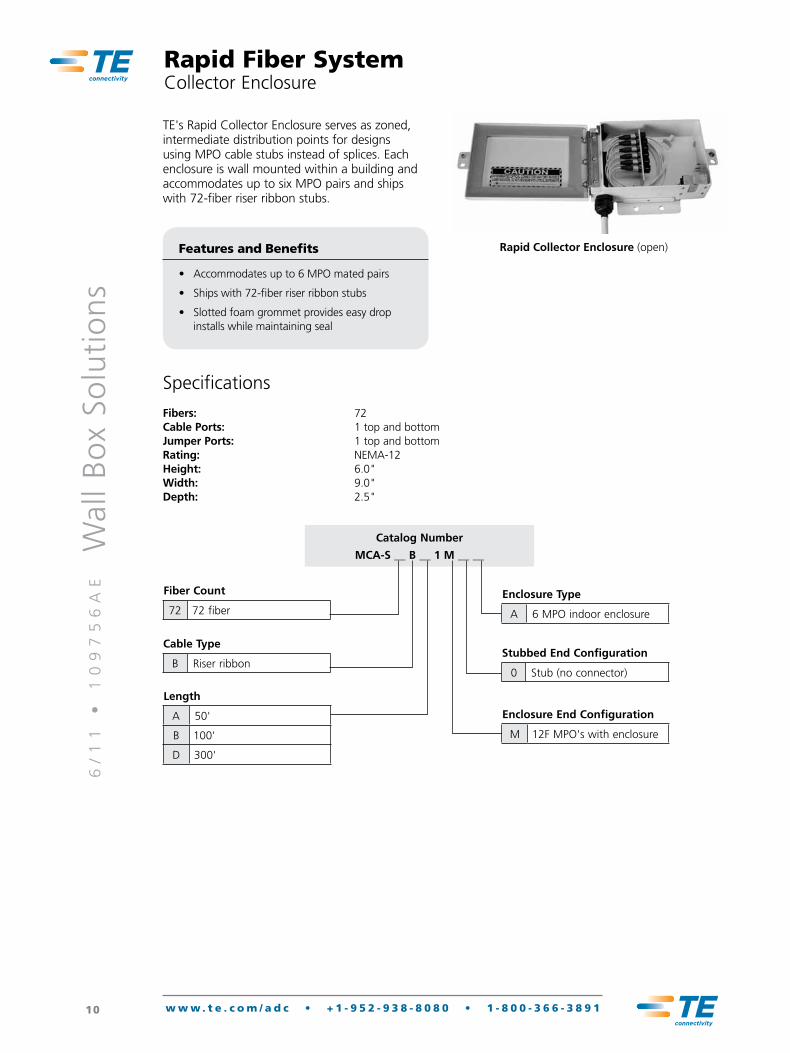
Rapid Fiber SystemCollector Enclosure
TE's Rapid Collector Enclosure serves as zoned, intermediate distribution points for designs using MPO cable stubs instead of splices. Each enclosure is wall mounted within a building and accommodates up to six MPO pairs and ships with 72-fiber riser ribbon stubs.
Rapid Collector Enclosure (open)Features and Benefits
• Accommodates up to 6 MPO mated pairs
• Ships with 72-fiber riser ribbon stubs
• Slotted foam grommet provides easy drop installs while maintaining seal
Catalog Number
MCA-S __ B __ 1 M __ __
Fiber Count
72 72 fiber
Cable Type
B Riser ribbon
Length
A 50'
B 100'
D 300'
Enclosure Type
A 6 MPO indoor enclosure
Stubbed End Configuration
0 Stub (no connector)
Enclosure End Configuration
M 12F MPO's with enclosure
Specifications
Fibers: 72Cable Ports: 1 top and bottomJumper Ports: 1 top and bottomRating: NEMA-12Height: 6.0"Width: 9.0"Depth: 2.5"
6/
11
•
1
09
75
6A
E
Wal
l B
ox
Solu
tio
ns
11 w w w . t e . c o m / a d c • + 1 - 9 5 2 - 9 3 8 - 8 0 8 0 • 1 - 8 0 0 - 3 6 6 - 3 8 9 1
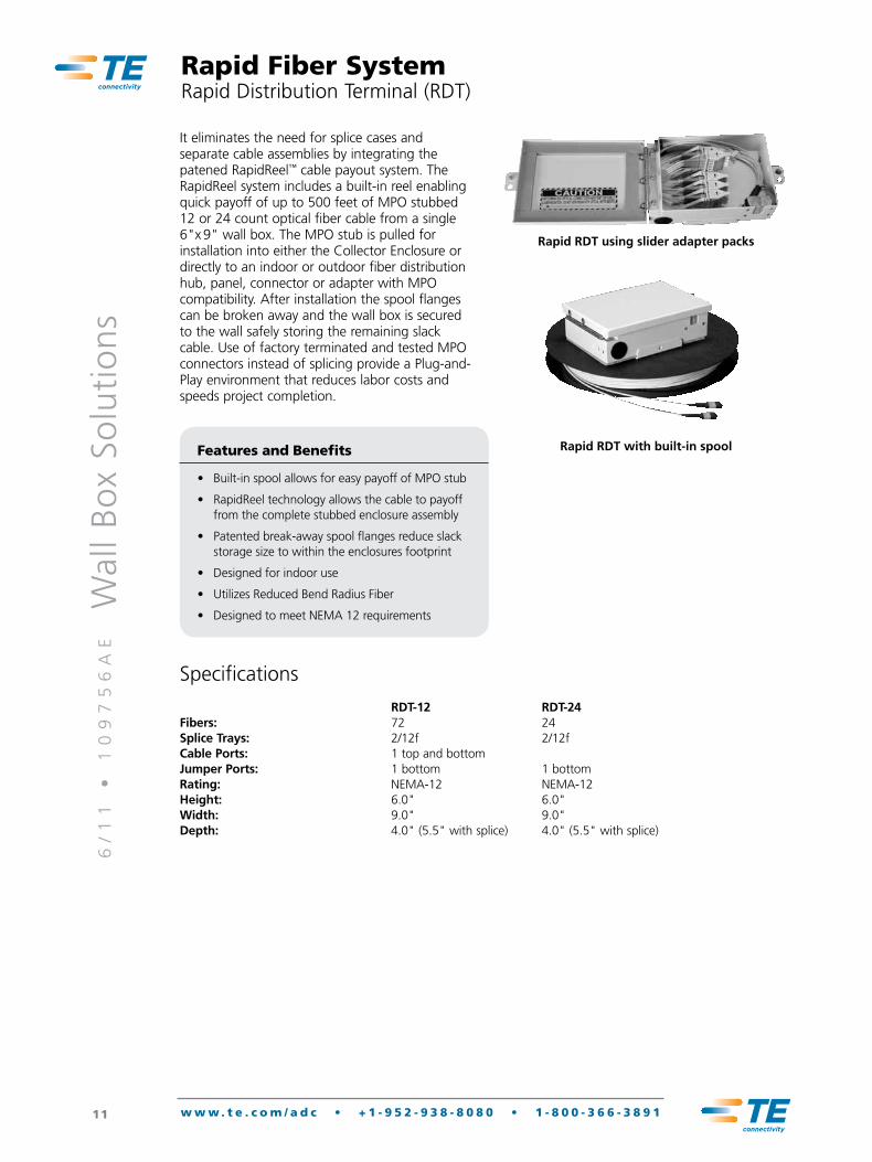
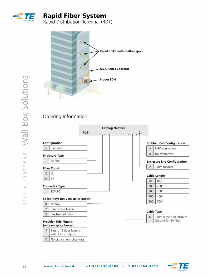
Rapid Fiber SystemRapid Distribution Terminal (RDT)
It eliminates the need for splice cases and separate cable assemblies by integrating the patened RapidReel™ cable payout system. The RapidReel system includes a built-in reel enabling quick payoff of up to 500 feet of MPO stubbed 12 or 24 count optical fiber cable from a single 6"x 9" wall box. The MPO stub is pulled for installation into either the Collector Enclosure or directly to an indoor or outdoor fiber distribution hub, panel, connector or adapter with MPO compatibility. After installation the spool flanges can be broken away and the wall box is secured to the wall safely storing the remaining slack cable. Use of factory terminated and tested MPO connectors instead of splicing provide a Plug-and-Play environment that reduces labor costs and speeds project completion.
Rapid RDT with built-in spoolFeatures and Benefits
• Built-in spool allows for easy payoff of MPO stub
• RapidReel technology allows the cable to payoff from the complete stubbed enclosure assembly
• Patented break-away spool flanges reduce slack storage size to within the enclosures footprint
• Designed for indoor use
• Utilizes Reduced Bend Radius Fiber
• Designed to meet NEMA 12 requirements
Rapid RDT using slider adapter packs
Specifications
RDT-12 RDT-24Fibers: 72 24Splice Trays: 2/12f 2/12fCable Ports: 1 top and bottomJumper Ports: 1 bottom 1 bottomRating: NEMA-12 NEMA-12Height: 6.0" 6.0"Width: 9.0" 9.0"Depth: 4.0" (5.5" with splice) 4.0" (5.5" with splice)
6/
11
•
1
09
75
6A
E
Wal
l B
ox
Solu
tio
ns
12 w w w . t e . c o m / a d c • + 1 - 9 5 2 - 9 3 8 - 8 0 8 0 • 1 - 8 0 0 - 3 6 6 - 3 8 9 1
Rapid Fiber SystemRapid Distribution Terminal (RDT)
Ordering Information
Enclosure Type
J 24 fiber
Catalog Number
RDT- __ __ __ __ __ __ __ __ __ __ __ 2 __
Configuration
S Standard
Fiber Count
12 12
24 24
Connector Type
J SC/APC
Splice Trays (only on splice boxes)
0 No tray
2 Heat shrink fusion
3 Mechanical/ribbon
Provider Side Pigtails (only on splice boxes)
P 3 mm, 12 fiber fanouts with 2 mm outputs
0 No pigtails, no splice trays
Cable Type
D 3 mm loose tube plenum (zipcord for 24 fiber)
Stubbed End Configuration
A MPO connectors
0 No connectors
Enclosure End Configuration
2 2 mm fanouts
Cable Length
100 100'
200 200'
300 300'
400 400'
500 500'
Rapid RDT's with Built-in Spool
MCA-Series Collector
Indoor FDH
6/
11
•
1
09
75
6A
E
Wal
l B
ox
Solu
tio
ns
13 w w w . t e . c o m / a d c • + 1 - 9 5 2 - 9 3 8 - 8 0 8 0 • 1 - 8 0 0 - 3 6 6 - 3 8 9 1
Outdoor Wall Box SolutionsSmall Outdoor Fiber Distribution Terminal (oFDT)
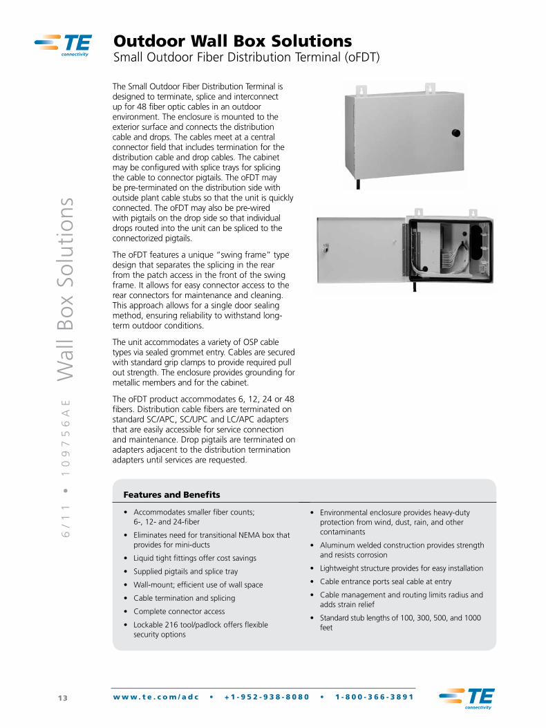
The Small Outdoor Fiber Distribution Terminal is designed to terminate, splice and interconnect up for 48 fiber optic cables in an outdoor environment. The enclosure is mounted to the exterior surface and connects the distribution cable and drops. The cables meet at a central connector field that includes termination for the distribution cable and drop cables. The cabinet may be configured with splice trays for splicing the cable to connector pigtails. The oFDT may be pre-terminated on the distribution side with outside plant cable stubs so that the unit is quickly connected. The oFDT may also be pre-wired with pigtails on the drop side so that individual drops routed into the unit can be spliced to the connectorized pigtails.
The oFDT features a unique “swing frame” type design that separates the splicing in the rear from the patch access in the front of the swing frame. It allows for easy connector access to the rear connectors for maintenance and cleaning. This approach allows for a single door sealing method, ensuring reliability to withstand long-term outdoor conditions.
The unit accommodates a variety of OSP cable types via sealed grommet entry. Cables are secured with standard grip clamps to provide required pull out strength. The enclosure provides grounding for metallic members and for the cabinet.
The oFDT product accommodates 6, 12, 24 or 48 fibers. Distribution cable fibers are terminated on standard SC/APC, SC/UPC and LC/APC adapters that are easily accessible for service connection and maintenance. Drop pigtails are terminated on adapters adjacent to the distribution termination adapters until services are requested.
Features and Benefits
• Accommodates smaller fiber counts; 6-, 12- and 24-fiber
• Eliminates need for transitional NEMA box that provides for mini-ducts
• Liquid tight fittings offer cost savings
• Supplied pigtails and splice tray
• Wall-mount; efficient use of wall space
• Cable termination and splicing
• Complete connector access
• Lockable 216 tool/padlock offers flexible security options
• Environmental enclosure provides heavy-duty protection from wind, dust, rain, and other contaminants
• Aluminum welded construction provides strength and resists corrosion
• Lightweight structure provides for easy installation
• Cable entrance ports seal cable at entry
• Cable management and routing limits radius and adds strain relief
• Standard stub lengths of 100, 300, 500, and 1000 feet

6/
11
•
1
09
75
6A
E
Wal
l B
ox
Solu
tio
ns
14 w w w . t e . c o m / a d c • + 1 - 9 5 2 - 9 3 8 - 8 0 8 0 • 1 - 8 0 0 - 3 6 6 - 3 8 9 1
Outdoor Wall Box SolutionsSmall Outdoor Fiber Distribution Terminal (oFDT)
Catalog Number
FDT- __ __ __ __ __ N X __ __ __ __ 0
Enclosure
G oFDT-48 (Available with -6, -12, -24 and -48 Fibers)
Splice Tray
0 No Tray
2 Heat Shrink Fusion
3 Mechanical/Ribbon
Fiber Count
06 6 Fiber
12 12 Fibers
24 24 Fibers
48 48 Fibers
Stub Length
000 0 Feet (Pigtail Option)
025 25 Feet
100 100 Feet
200 200 Feet
300 300 Feet
500 500 Feet
Cable Type
Pigtails
A Bare Ribbon Pigtail Assembly
B 12 Fiber Software Bundle*
Stubs
S Ribbon OSP w/Conn
R Ribbon IFC w/Conn
T Loose Tube OSP w/Conn
V Loose Tube IFC w/Conn
*900 micron fiber bundled in a soft jacket.
Connector Type
Singlemode
J SC/APC
N SC/UPC
K LC/UPC
Multimode
9 MMSC
6 MMLC
6/
11
•
1
09
75
6A
E
Wal
l B
ox
Solu
tio
ns
15 w w w . t e . c o m / a d c • + 1 - 9 5 2 - 9 3 8 - 8 0 8 0 • 1 - 8 0 0 - 3 6 6 - 3 8 9 1
Outdoor Wall Box SolutionsLarge Outdoor Fiber Distribution Terminal (oFDT)
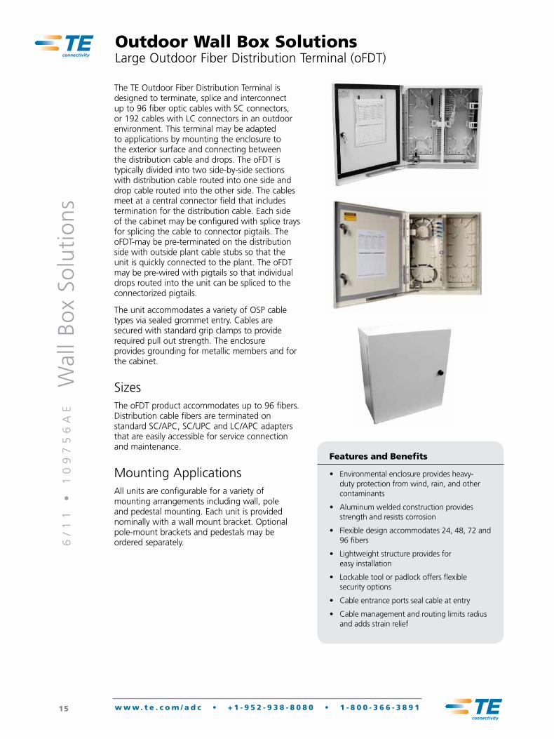
The TE Outdoor Fiber Distribution Terminal is designed to terminate, splice and interconnect up to 96 fiber optic cables with SC connectors, or 192 cables with LC connectors in an outdoor environment. This terminal may be adapted to applications by mounting the enclosure to the exterior surface and connecting between the distribution cable and drops. The oFDT is typically divided into two side-by-side sections with distribution cable routed into one side and drop cable routed into the other side. The cables meet at a central connector field that includes termination for the distribution cable. Each side of the cabinet may be configured with splice trays for splicing the cable to connector pigtails. The oFDT-may be pre-terminated on the distribution side with outside plant cable stubs so that the unit is quickly connected to the plant. The oFDT may be pre-wired with pigtails so that individual drops routed into the unit can be spliced to the connectorized pigtails.
The unit accommodates a variety of OSP cable types via sealed grommet entry. Cables are secured with standard grip clamps to provide required pull out strength. The enclosure provides grounding for metallic members and for the cabinet.
SizesThe oFDT product accommodates up to 96 fibers. Distribution cable fibers are terminated on standard SC/APC, SC/UPC and LC/APC adapters that are easily accessible for service connection and maintenance.
Mounting ApplicationsAll units are configurable for a variety of mounting arrangements including wall, pole and pedestal mounting. Each unit is provided nominally with a wall mount bracket. Optional pole-mount brackets and pedestals may be ordered separately.
Features and Benefits
• Environmental enclosure provides heavy-duty protection from wind, rain, and other contaminants
• Aluminum welded construction provides strength and resists corrosion
• Flexible design accommodates 24, 48, 72 and 96 fibers
• Lightweight structure provides for easy installation
• Lockable tool or padlock offers flexible security options
• Cable entrance ports seal cable at entry
• Cable management and routing limits radius and adds strain relief
6/
11
•
1
09
75
6A
E
Wal
l B
ox
Solu
tio
ns
16 w w w . t e . c o m / a d c • + 1 - 9 5 2 - 9 3 8 - 8 0 8 0 • 1 - 8 0 0 - 3 6 6 - 3 8 9 1
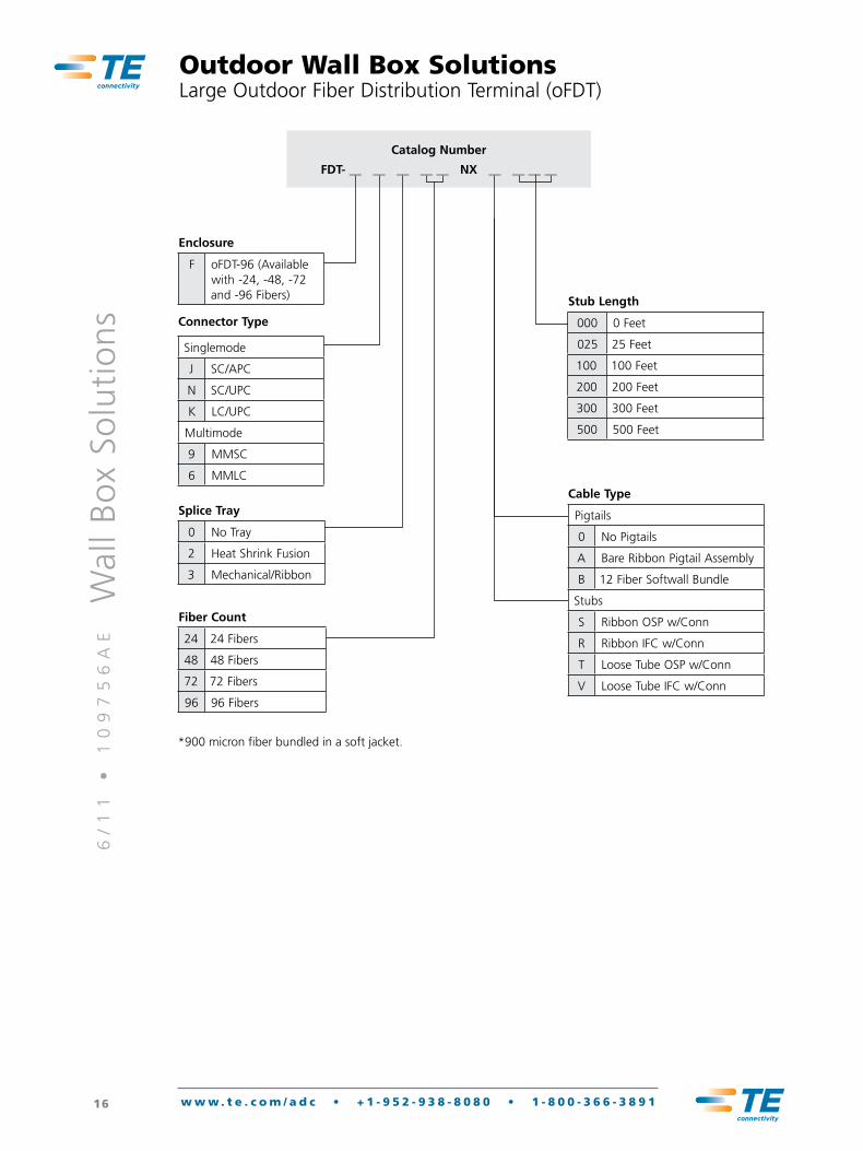
Outdoor Wall Box SolutionsLarge Outdoor Fiber Distribution Terminal (oFDT)
Enclosure
F oFDT-96 (Available with -24, -48, -72 and -96 Fibers)
Splice Tray
0 No Tray
2 Heat Shrink Fusion
3 Mechanical/Ribbon
Fiber Count
24 24 Fibers
48 48 Fibers
72 72 Fibers
96 96 Fibers
Catalog Number
FDT- __ __ __ __ __ NX __ __ __ __
Cable Type
Pigtails
0 No Pigtails
A Bare Ribbon Pigtail Assembly
B 12 Fiber Softwall Bundle
Stubs
S Ribbon OSP w/Conn
R Ribbon IFC w/Conn
T Loose Tube OSP w/Conn
V Loose Tube IFC w/Conn
Stub Length
000 0 Feet
025 25 Feet
100 100 Feet
200 200 Feet
300 300 Feet
500 500 Feet
*900 micron fiber bundled in a soft jacket.
Connector Type
Singlemode
J SC/APC
N SC/UPC
K LC/UPC
Multimode
9 MMSC
6 MMLC

6/
11
•
1
09
75
6A
E
Wal
l B
ox
Solu
tio
ns
17 w w w . t e . c o m / a d c • + 1 - 9 5 2 - 9 3 8 - 8 0 8 0 • 1 - 8 0 0 - 3 6 6 - 3 8 9 1
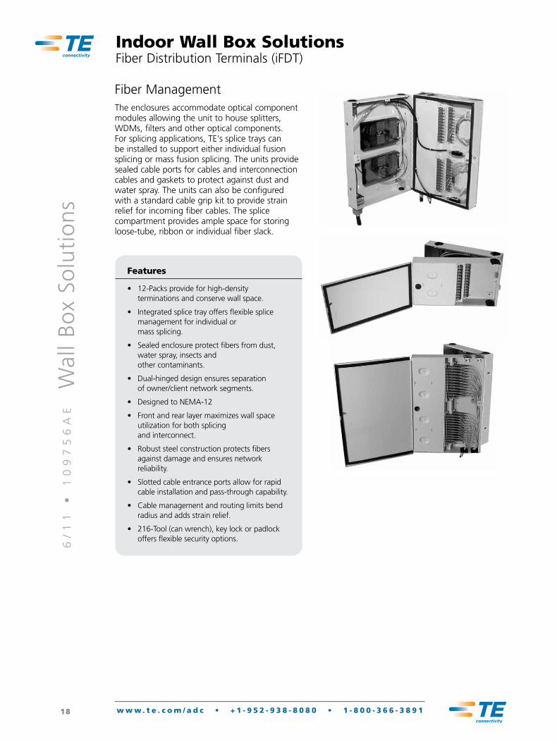
Indoor Wall Box SolutionsFiber Distribution Terminals (iFDT)
Product DescriptionThe TE Indoor Fiber Distribution Terminal (iFDT) series provides Customer Premises Equipment applications with a compact and secure family of enclosures for connecting fiber cables within building entrance locations, communication closets, computer rooms and other indoor environments. The iFDT products utilize a rugged double-hinged design that effectively isolates the splicing and cable termination in the rear compartment from the jumper interconnection in the front compartment. Separating the cable splicing and termination function from the interconnection function allows the unit to be used as a dual-access product with secure lockable access provided for each compartment.
The layered iFDT and staggered interconnection field provides ease of access to all connections.
SizesThe iFDT products are designed to splice and terminate fibers in a range of sizes including 6, 12, 24, 48, 72, and 96 fibers.
Mounting ApplicationsThe TE iFDT Series cabinets are for indoor wall mount applications and are designed to NEMA-12 rating. The dual hinged design allows complete front and rear access. The two secure doors are locked with a standard can wrench tool and may optionally be secured with a standard pad-lock. The unit may also be configured for single lock entry thus allowing the products to be used for single access applications.
6/
11
•
1
09
75
6A
E
Wal
l B
ox
Solu
tio
ns
18 w w w . t e . c o m / a d c • + 1 - 9 5 2 - 9 3 8 - 8 0 8 0 • 1 - 8 0 0 - 3 6 6 - 3 8 9 1
Indoor Wall Box SolutionsFiber Distribution Terminals (iFDT)
Fiber ManagementThe enclosures accommodate optical component modules allowing the unit to house splitters, WDMs, filters and other optical components. For splicing applications, TE's splice trays can be installed to support either individual fusion splicing or mass fusion splicing. The units provide sealed cable ports for cables and interconnection cables and gaskets to protect against dust and water spray. The units can also be configured with a standard cable grip kit to provide strain relief for incoming fiber cables. The splice compartment provides ample space for storing loose-tube, ribbon or individual fiber slack.
Features
• 12-Packs provide for high-density terminations and conserve wall space.
• Integrated splice tray offers flexible splice management for individual or mass splicing.
• Sealed enclosure protect fibers from dust, water spray, insects and other contaminants.
• Dual-hinged design ensures separation of owner/client network segments.
• Designed to NEMA-12
• Front and rear layer maximizes wall space utilization for both splicing and interconnect.
• Robust steel construction protects fibers against damage and ensures network reliability.
• Slotted cable entrance ports allow for rapid cable installation and pass-through capability.
• Cable management and routing limits bend radius and adds strain relief.
• 216-Tool (can wrench), key lock or padlock offers flexible security options.
6/
11
•
1
09
75
6A
E
Wal
l B
ox
Solu
tio
ns
19 w w w . t e . c o m / a d c • + 1 - 9 5 2 - 9 3 8 - 8 0 8 0 • 1 - 8 0 0 - 3 6 6 - 3 8 9 1
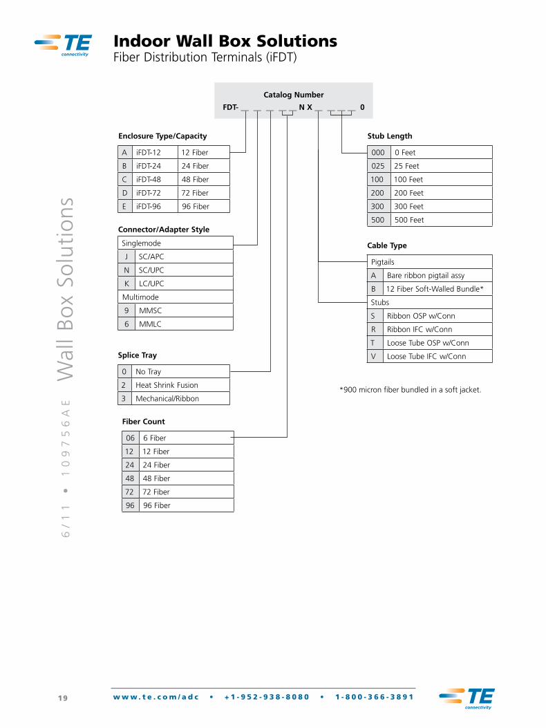
Indoor Wall Box SolutionsFiber Distribution Terminals (iFDT)
Catalog Number
FDT- __ __ __ __ __ N X __ __ __ __ 0
Enclosure Type/Capacity
A iFDT-12 12 Fiber
B iFDT-24 24 Fiber
C iFDT-48 48 Fiber
D iFDT-72 72 Fiber
E iFDT-96 96 Fiber
Cable Type
Pigtails
A Bare ribbon pigtail assy
B 12 Fiber Soft-Walled Bundle*
Stubs
S Ribbon OSP w/Conn
R Ribbon IFC w/Conn
T Loose Tube OSP w/Conn
V Loose Tube IFC w/Conn
Stub Length
000 0 Feet
025 25 Feet
100 100 Feet
200 200 Feet
300 300 Feet
500 500 Feet
Splice Tray
0 No Tray
2 Heat Shrink Fusion
3 Mechanical/Ribbon
Fiber Count
06 6 Fiber
12 12 Fiber
24 24 Fiber
48 48 Fiber
72 72 Fiber
96 96 Fiber
Connector/Adapter Style
Singlemode
J SC/APC
N SC/UPC
K LC/UPC
Multimode
9 MMSC
6 MMLC
*900 micron fiber bundled in a soft jacket.
6/
11
•
1
09
75
6A
E
Wal
l B
ox
Solu
tio
ns
20 w w w . t e . c o m / a d c • + 1 - 9 5 2 - 9 3 8 - 8 0 8 0 • 1 - 8 0 0 - 3 6 6 - 3 8 9 1
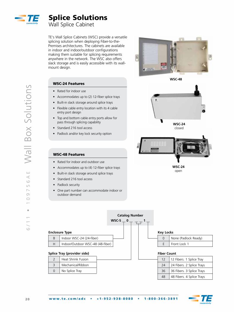
WSC-48
Splice SolutionsWall Splice Cabinet
TE's Wall Splice Cabinets (WSC) provide a versatile splicing solution when deploying Fiber-to-the-Premises architectures. The cabinets are available in indoor and indoor/outdoor configurations making them suitable for splicing requirements anywhere in the network. The WSC also offers slack storage and is easily accessible with its wall-mount design.
WSC-24 Features
• Rated for indoor use
• Accommodates up to (2) 12-fiber splice trays
• Built-in slack storage around splice trays
• Flexible cable entry location with its 4 cable entry port design
• Top and bottom cable entry ports allow for pass through splicing capability
• Standard 216 tool access
• Padlock and/or key lock security option
WSC-48 Features
• Rated for indoor and outdoor use
• Accommodates up to (4) 12-fiber splice trays
• Built-in slack storage around splice trays
• Standard 216 tool access
• Padlock security
• One part number can accommodate indoor or outdoor demand
WSC-24 open
Catalog Number
WSC-S __ 0 __ __ __ 1 __
Key Locks
0 None (Padlock Ready)
E Front Lock 1
Fiber Count
12 12 Fibers. 1 Splice Tray
24 24 Fibers. 2 Splice Trays
36 36 Fibers. 3 Splice Trays
48 48 Fibers. 4 Splice Trays
Enclosure Type
B Indoor WSC-24 (24-fiber)
H Indoor/Outdoor WSC-48 (48-fiber)
Splice Tray (provider side)
2 Heat Shrink Fusion
3 Mechanical/Ribbon
0 No Splice Tray
WSC-24 closed
6/
11
•
1
09
75
6A
E
Wal
l B
ox
Solu
tio
ns
21 w w w . t e . c o m / a d c • + 1 - 9 5 2 - 9 3 8 - 8 0 8 0 • 1 - 8 0 0 - 3 6 6 - 3 8 9 1
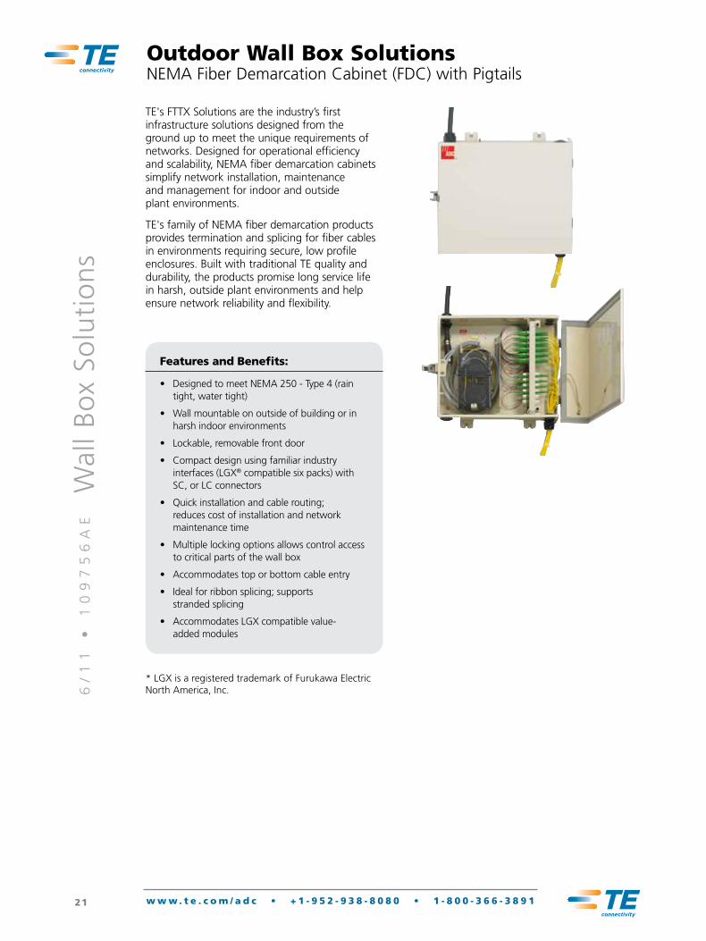
TE's FTTX Solutions are the industry’s first infrastructure solutions designed from the ground up to meet the unique requirements of networks. Designed for operational efficiency and scalability, NEMA fiber demarcation cabinets simplify network installation, maintenance and management for indoor and outside plant environments.
TE's family of NEMA fiber demarcation products provides termination and splicing for fiber cables in environments requiring secure, low profile enclosures. Built with traditional TE quality and durability, the products promise long service life in harsh, outside plant environments and help ensure network reliability and flexibility.
Features and Benefits:
• Designed to meet NEMA 250 - Type 4 (rain tight, water tight)
• Wall mountable on outside of building or in harsh indoor environments
• Lockable, removable front door
• Compact design using familiar industry interfaces (LGX® compatible six packs) with SC, or LC connectors
• Quick installation and cable routing; reduces cost of installation and network maintenance time
• Multiple locking options allows control access to critical parts of the wall box
• Accommodates top or bottom cable entry
• Ideal for ribbon splicing; supports stranded splicing
• Accommodates LGX compatible value-added modules
Outdoor Wall Box SolutionsNEMA Fiber Demarcation Cabinet (FDC) with Pigtails
* LGX is a registered trademark of Furukawa Electric North America, Inc.

6/
11
•
1
09
75
6A
E
Wal
l B
ox
Solu
tio
ns
22 w w w . t e . c o m / a d c • + 1 - 9 5 2 - 9 3 8 - 8 0 8 0 • 1 - 8 0 0 - 3 6 6 - 3 8 9 1
Connector/Adapter Style
1 12 fibers
2 24 fibers
4 48 fibers
Catalog Number
FDC- __ __ __ __ S X __ 0 __ 0 __ __ __ 0
Strength Member Tie-offs
0 No strength member tie-offs included
1 1 strength member tie-off included
Splice Tray/Chip Style
0 None or N/A
2 Heat shrink fusion
3 Mechanical/ribbon
Pigtail or Adapter Type
A Adapters only
R 12 fiber ribbon
4 12-fiber maxi-strip soft-wall bundle (stranded)
Compression Fittings
0 No compression fitting
1 1 compression fitting
2 2 compression fittings
Number of 6 packs loaded
Outdoor Wall Box SolutionsNEMA Fiber Demarcation Cabinet (FDC) with Pigtails
Number of Doors
L 1 door (NEMA 4)
Connector/Adapter Style
Singlemode
J SC/APC
N SC/UPC
K LC/UPC
Multimode
9 MMSC
6 MMLC
6/
11
•
1
09
75
6A
E
Wal
l B
ox
Solu
tio
ns
23 w w w . t e . c o m / a d c • + 1 - 9 5 2 - 9 3 8 - 8 0 8 0 • 1 - 8 0 0 - 3 6 6 - 3 8 9 1
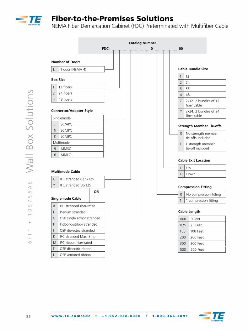
Box Size
1 12 fibers
2 24 fibers
4 48 fibers
Catalog Number
FDC- __ __ __ __ __ __ __ 0 __ __ __ __ 00
Number of Doors
L 1 door (NEMA 4)
Multimode Cable
C IFC stranded 62.5/125
Y IFC stranded 50/125
Strength Member Tie-offs
0 No strength member tie-offs included
1 1 strength member tie-off included
OR
Singlemode Cable
A IFC stranded riser-rated
F Plenum stranded
G OSP single armor stranded
H Indoor-outdoor stranded
J OSP dielectric stranded
K IFC stranded Maxi-Strip
M IFC ribbon riser-rated
T OSP dielectric ribbon
L OSP armored ribbon
Cable Exit Location
U Up
D Down
Compression Fitting
0 No compression fitting
1 1 compression fitting
Cable Bundle Size
1 12
2 24
3 36
4 48
Z 2x12. 2 bundles of 12 fiber cable
Y 2x24. 2 bundles of 24 fiber cable
Fiber-to-the-Premises SolutionsNEMA Fiber Demarcation Cabinet (FDC) Preterminated with Multifiber Cable
Connector/Adapter Style
Singlemode
J SC/APC
N SC/UPC
K LC/UPC
Multimode
9 MMSC
6 MMLC
Cable Length
000 0 Feet
025 25 Feet
100 100 Feet
200 200 Feet
300 300 Feet
500 500 Feet

6/
11
•
1
09
75
6A
E
Wal
l B
ox
Solu
tio
ns
24 w w w . t e . c o m / a d c • + 1 - 9 5 2 - 9 3 8 - 8 0 8 0 • 1 - 8 0 0 - 3 6 6 - 3 8 9 1
FL1Indoor Fiber Wall Mount Boxes
TE's FL1 indoor fiber termination products include a variety of two door wall mount box configurations. These products are designed specifically to act as part of the fiber distribution system in an enterprise networkcell site backhaul network, or as the demarcation point for the service provider at the customer’s location. FL1 products utilize adapter pack technology, which enables service providers to add new subscriber connections as needed —deferring unnecessary CAPEX.
Excellent labeling, grommets, door latches and ribbon pigtail routing reinforce the value these products bring to the physical layer of any network with higher quality and reliability, greater operational efficiencies, and network simplification.
Features/Benefits:
• Economical, "build-as-you-grow" solution
• Quick installation
• Compact size
• Durability
• Single catalog number ordering
• Single package shipping
12-Position 11.2 x 13 x 3.6" (28.4 x 33 x 9.1 cm)
24-Position 15.1 x 14.0 x 3.6" (38.4 x 35.6 x 9.1 cm)
48-Position 17.7 x 17 x 6.2" (45 x 43.1 x 15.7 cm)
72-Position 17.7 x 17 x 6.2" (45 x 43. 1 x 15.7 cm)
Two Door Fiber Wall Mount Boxes The FL1 two-door, wall-mount boxes feature a unique design and many integrated features such as:
• Multiple, configurable locking options that allow users and service providers separate access for security
• Acceptance of strength member tie-off hardware
• Acceptance of cable clamps at each corner
Grounding screws, mounting screws, and dust caps are included with each panel. More accessories are available on pages 32-35.
FL1 Dimensions
12-Position
6/
11
•
1
09
75
6A
E
Wal
l B
ox
Solu
tio
ns
25 w w w . t e . c o m / a d c • + 1 - 9 5 2 - 9 3 8 - 8 0 8 0 • 1 - 8 0 0 - 3 6 6 - 3 8 9 1
FL1Indoor Fiber Wall Mount Boxes
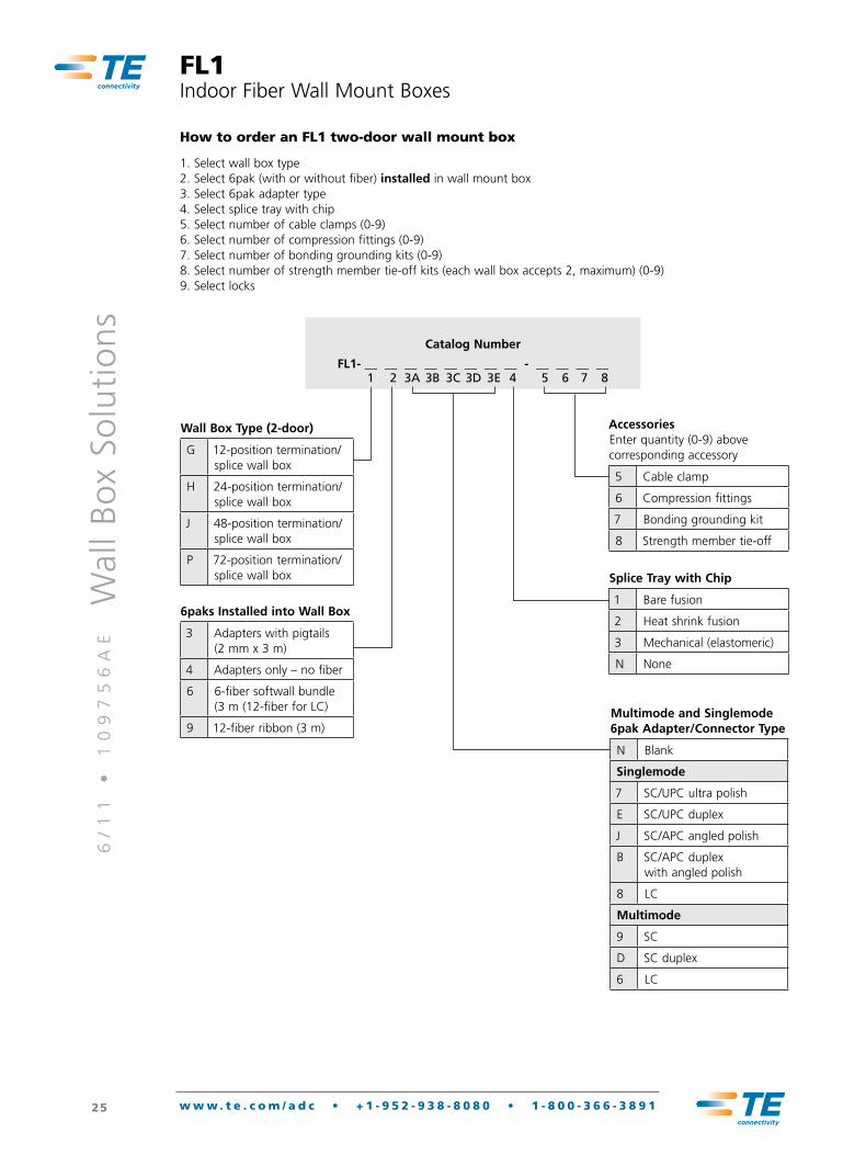
How to order an FL1 two-door wall mount box
1. Select wall box type2. Select 6pak (with or without fiber) installed in wall mount box 3. Select 6pak adapter type4. Select splice tray with chip5. Select number of cable clamps (0-9)6. Select number of compression fittings (0-9)7. Select number of bonding grounding kits (0-9)8. Select number of strength member tie-off kits (each wall box accepts 2, maximum) (0-9)9. Select locks
Wall Box Type (2-door)
G 12-position termination/splice wall box
H 24-position termination/splice wall box
J 48-position termination/splice wall box
P 72-position termination/splice wall box
6paks Installed into Wall Box
3 Adapters with pigtails (2 mm x 3 m)
4 Adapters only – no fiber
6 6-fiber softwall bundle (3 m (12-fiber for LC)
9 12-fiber ribbon (3 m)Multimode and Singlemode 6pak Adapter/Connector Type
N Blank
Singlemode
7 SC/UPC ultra polish
E SC/UPC duplex
J SC/APC angled polish
B SC/APC duplex with angled polish
8 LC
Multimode
9 SC
D SC duplex
6 LC
Accessories Enter quantity (0-9) above corresponding accessory
5 Cable clamp
6 Compression fittings
7 Bonding grounding kit
8 Strength member tie-off
Splice Tray with Chip
1 Bare fusion
2 Heat shrink fusion
3 Mechanical (elastomeric)
N None
Catalog Number
FL1- __ __ __ __ __ __ __ __ - __ __ __ __1 2 3A 3B 3C 3D 3E 4 5 6 7 8
6/
11
•
1
09
75
6A
E
Wal
l B
ox
Solu
tio
ns
26 w w w . t e . c o m / a d c • + 1 - 9 5 2 - 9 3 8 - 8 0 8 0 • 1 - 8 0 0 - 3 6 6 - 3 8 9 1
FL16pak Adapter Packs
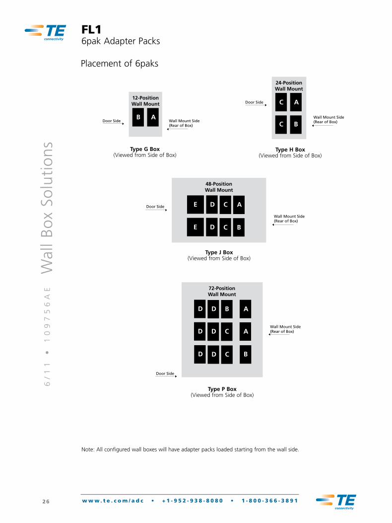
Note: All configured wall boxes will have adapter packs loaded starting from the wall side.
Placement of 6paks
B A
12-PositionWall Mount
Type G Box Viewed from Equipment Side
Wall Mount Side(Rear of Box)
Door Side
Type G Box(Viewed from Side of Box)
C A
24-PositionWall Mount
Type H Box Viewed from Equipment Side
Wall Mount Side(Rear of Box)
Door Side
C B
Type H Box(Viewed from Side of Box)
E D
48-PositionWall Mount
Type J Box Viewed from Equipment Side
Wall Mount Side(Rear of Box)
Door Side
E D
C
C
A
B
Type J Box(Viewed from Side of Box)
D
72-PositionWall Mount
Type P Box Viewed from Equipment Side
Wall Mount Side(Rear of Box)
Door Side
D
D
D
B
C
D D C
A
A
B
Type P Box(Viewed from Side of Box)
6/
11
•
1
09
75
6A
E
Wal
l B
ox
Solu
tio
ns
27 w w w . t e . c o m / a d c • + 1 - 9 5 2 - 9 3 8 - 8 0 8 0 • 1 - 8 0 0 - 3 6 6 - 3 8 9 1
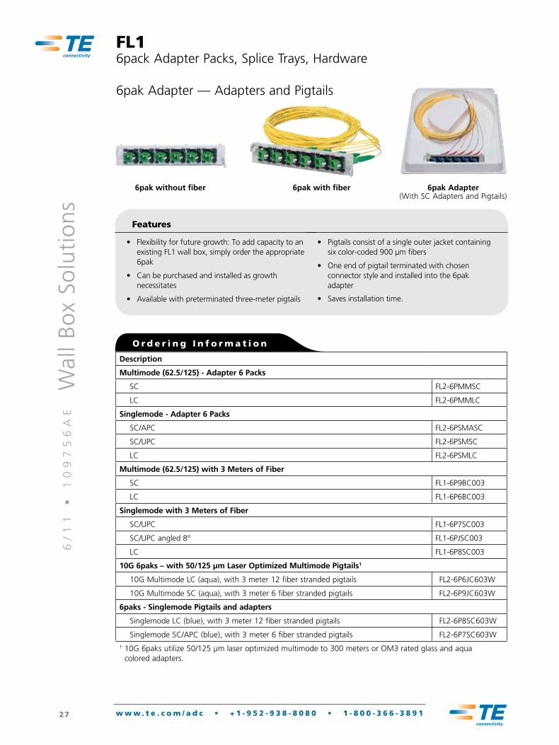
6pak without fiber 6pak with fiber
Description
Multimode (62.5/125) - Adapter 6 Packs
SC FL2-6PMMSC
LC FL2-6PMMLC
Singlemode - Adapter 6 Packs
SC/APC FL2-6PSMASC
SC/UPC FL2-6PSMSC
LC FL2-6PSMLC
Multimode (62.5/125) with 3 Meters of Fiber
SC FL1-6P9BC003
LC FL1-6P6BC003
Singlemode with 3 Meters of Fiber
SC/UPC FL1-6P7SC003
SC/UPC angled 8° FL1-6PJSC003
LC FL1-6P8SC003
10G 6paks – with 50/125 µm Laser Optimized Multimode Pigtails1
10G Multimode LC (aqua), with 3 meter 12 fiber stranded pigtails FL2-6P6JC603W
10G Multimode SC (aqua), with 3 meter 6 fiber stranded pigtails FL2-6P9JC603W
6paks - Singlemode Pigtails and adapters
Singlemode LC (blue), with 3 meter 12 fiber stranded pigtails FL2-6P8SC603W
Singlemode SC/APC (blue), with 3 meter 6 fiber stranded pigtails FL2-6P7SC603W1 10G 6paks utilize 50/125 µm laser optimized multimode to 300 meters or OM3 rated glass and aqua
colored adapters.
O r d e r i n g I n f o r m a t i o n
6pak Adapter(With SC Adapters and Pigtails)
6pak Adapter — Adapters and Pigtails
FL16pack Adapter Packs, Splice Trays, Hardware
Features
• Flexibility for future growth: To add capacity to an existing FL1 wall box, simply order the appropriate 6pak
• Can be purchased and installed as growth necessitates
• Available with preterminated three-meter pigtails
• Pigtails consist of a single outer jacket containing six color-coded 900 µm fibers
• One end of pigtail terminated with chosen connector style and installed into the 6pak adapter
• Saves installation time.
6/
11
•
1
09
75
6A
E
Wal
l B
ox
Solu
tio
ns
28 w w w . t e . c o m / a d c • + 1 - 9 5 2 - 9 3 8 - 8 0 8 0 • 1 - 8 0 0 - 3 6 6 - 3 8 9 1
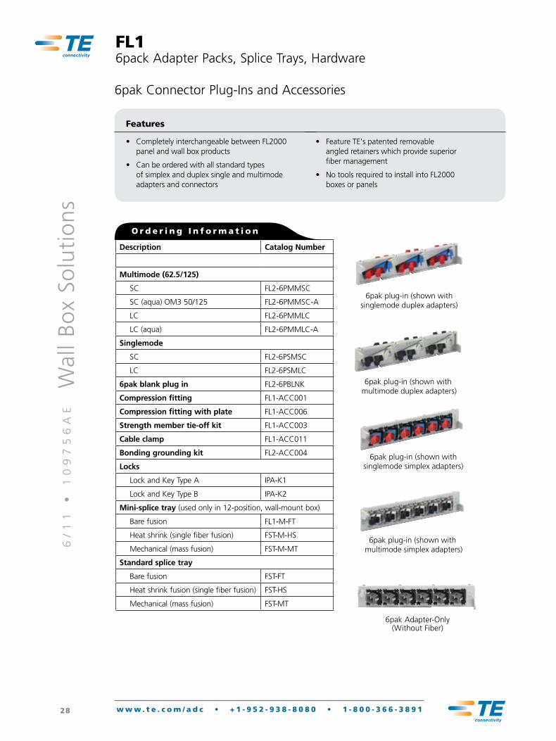
6pak Connector Plug-Ins and Accessories
Features
• Completely interchangeable between FL2000 panel and wall box products
• Can be ordered with all standard types of simplex and duplex single and multimode adapters and connectors
• Feature TE's patented removable angled retainers which provide superior fiber management
• No tools required to install into FL2000 boxes or panels
6pak plug-in (shown with singlemode simplex adapters)
6pak plug-in (shown with multimode simplex adapters)
6pak plug-in (shown with singlemode duplex adapters)
6pak plug-in (shown with multimode duplex adapters)
O r d e r i n g I n f o r m a t i o n
6pak Adapter-Only (Without Fiber)
FL16pack Adapter Packs, Splice Trays, Hardware
Description Catalog Number
Multimode (62.5/125)
SC FL2-6PMMSC
SC (aqua) OM3 50/125 FL2-6PMMSC-A
LC FL2-6PMMLC
LC (aqua) FL2-6PMMLC-A
Singlemode
SC FL2-6PSMSC
LC FL2-6PSMLC
6pak blank plug in FL2-6PBLNK
Compression fitting FL1-ACC001
Compression fitting with plate FL1-ACC006
Strength member tie-off kit FL1-ACC003
Cable clamp FL1-ACC011
Bonding grounding kit FL2-ACC004
Locks
Lock and Key Type A IPA-K1
Lock and Key Type B IPA-K2
Mini-splice tray (used only in 12-position, wall-mount box)
Bare fusion FL1-M-FT
Heat shrink (single fiber fusion) FST-M-HS
Mechanical (mass fusion) FST-M-MT
Standard splice tray
Bare fusion FST-FT
Heat shrink fusion (single fiber fusion) FST-HS
Mechanical (mass fusion) FST-MT
6/
11
•
1
09
75
6A
E
Wal
l B
ox
Solu
tio
ns
29 w w w . t e . c o m / a d c • + 1 - 9 5 2 - 9 3 8 - 8 0 8 0 • 1 - 8 0 0 - 3 6 6 - 3 8 9 1
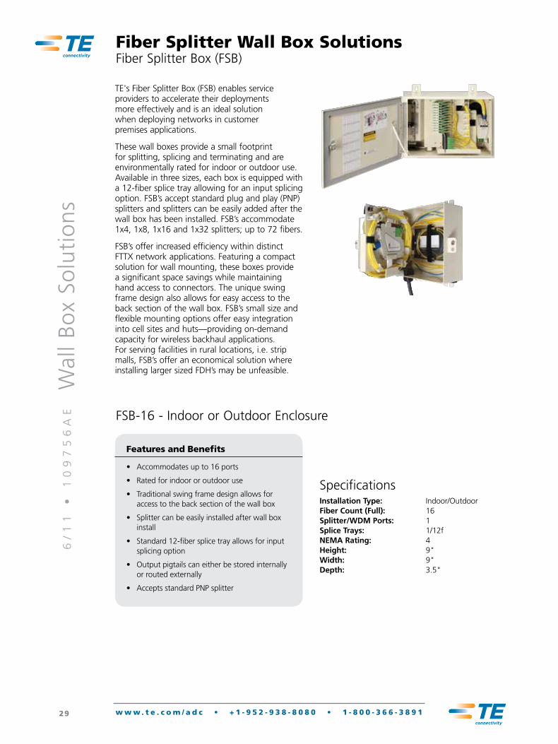
TE's Fiber Splitter Box (FSB) enables service providers to accelerate their deployments more effectively and is an ideal solution when deploying networks in customer premises applications.
These wall boxes provide a small footprint for splitting, splicing and terminating and are environmentally rated for indoor or outdoor use. Available in three sizes, each box is equipped with a 12-fiber splice tray allowing for an input splicing option. FSB’s accept standard plug and play (PNP) splitters and splitters can be easily added after the wall box has been installed. FSB’s accommodate 1x4, 1x8, 1x16 and 1x32 splitters; up to 72 fibers.
FSB’s offer increased efficiency within distinct FTTX network applications. Featuring a compact solution for wall mounting, these boxes provide a significant space savings while maintaining hand access to connectors. The unique swing frame design also allows for easy access to the back section of the wall box. FSB’s small size and flexible mounting options offer easy integration into cell sites and huts—providing on-demand capacity for wireless backhaul applications. For serving facilities in rural locations, i.e. strip malls, FSB’s offer an economical solution where installing larger sized FDH’s may be unfeasible.
Fiber Splitter Wall Box SolutionsFiber Splitter Box (FSB)
FSB-16 - Indoor or Outdoor Enclosure
Features and Benefits
• Accommodates up to 16 ports
• Rated for indoor or outdoor use
• Traditional swing frame design allows for access to the back section of the wall box
• Splitter can be easily installed after wall box install
• Standard 12-fiber splice tray allows for input splicing option
• Output pigtails can either be stored internally or routed externally
• Accepts standard PNP splitter
SpecificationsInstallation Type: Indoor/OutdoorFiber Count (Full): 16Splitter/WDM Ports: 1Splice Trays: 1/12fNEMA Rating: 4Height: 9"Width: 9"Depth: 3.5"
6/
11
•
1
09
75
6A
E
Wal
l B
ox
Solu
tio
ns
30 w w w . t e . c o m / a d c • + 1 - 9 5 2 - 9 3 8 - 8 0 8 0 • 1 - 8 0 0 - 3 6 6 - 3 8 9 1
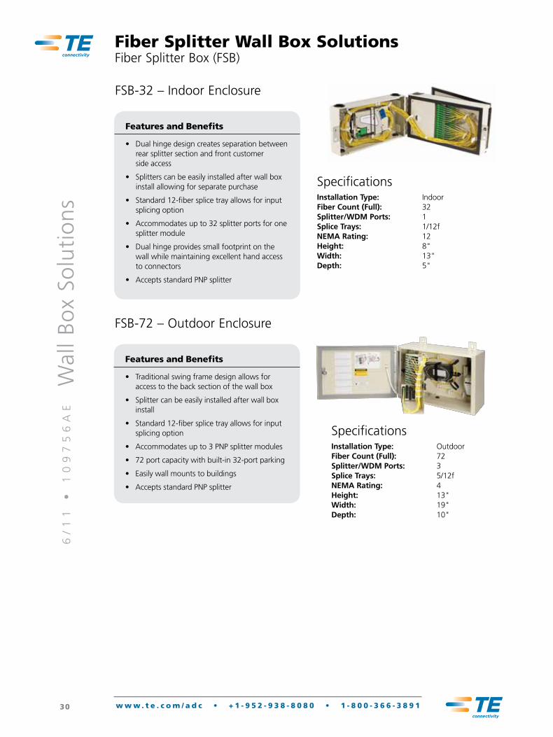
FSB-72 – Outdoor Enclosure
Features and Benefits
• Traditional swing frame design allows for access to the back section of the wall box
• Splitter can be easily installed after wall box install
• Standard 12-fiber splice tray allows for input splicing option
• Accommodates up to 3 PNP splitter modules
• 72 port capacity with built-in 32-port parking
• Easily wall mounts to buildings
• Accepts standard PNP splitter
Features and Benefits
• Dual hinge design creates separation between rear splitter section and front customer side access
• Splitters can be easily installed after wall box install allowing for separate purchase
• Standard 12-fiber splice tray allows for input splicing option
• Accommodates up to 32 splitter ports for one splitter module
• Dual hinge provides small footprint on the wall while maintaining excellent hand access to connectors
• Accepts standard PNP splitter
SpecificationsInstallation Type: OutdoorFiber Count (Full): 72Splitter/WDM Ports: 3Splice Trays: 5/12fNEMA Rating: 4Height: 13"Width: 19"Depth: 10"
SpecificationsInstallation Type: IndoorFiber Count (Full): 32Splitter/WDM Ports: 1Splice Trays: 1/12fNEMA Rating: 12Height: 8"Width: 13"Depth: 5"
Fiber Splitter Wall Box SolutionsFiber Splitter Box (FSB)
FSB-32 – Indoor Enclosure

6/
11
•
1
09
75
6A
E
Wal
l B
ox
Solu
tio
ns
31 w w w . t e . c o m / a d c • + 1 - 9 5 2 - 9 3 8 - 8 0 8 0 • 1 - 8 0 0 - 3 6 6 - 3 8 9 1
Connector Type
J SC/APC
N SC/UPC
Splice Tray (Feeder Side)
2 Heat Shrink Fusion
3 Mechanical/Ribbon
0 No Splice Tray
Fiber Count (Distribution)
12 12 Fibers
16 16 Fibers
32 32 Fibers
48 48 Fibers
72 72 Fibers
Splitter Type Installed
0 None Installed
A 1x32 Standard
C 1x16 Standard
J 1x8 Standard
L Dual 1x8 Standard
M Dual 1x16 Standard
N 1x4 Standard
P 2x16 Standard
U Dual 1x4 Standard
Enclosure Type
Code Description CapacitySize
(HxWxD)
B Indoor FSB-32 32-Fiber 8"x13.5"x5"
G Outdoor FSB-72 72-Fiber 13.5"x19"x8"
H Indr/Outdr FSB-16 16-Fiber 9"x9"x3.7"
Cable Type (Feeder Cable)
Adapters
0 Adapters Only (No Pigtail for Feeder)
Pigtails
A Splice-Ribbon Pigtail Assy
C Splice-Pigtails (900 Micron)
Stubs
S Ribbon OSP Cable
R Ribbon IFC Cable
T Loose Tube OSP Cable
V Loose Tube IFC Cable
M 900um IFNR Cable
Catalog Number
FSB- __ __ __ __ __ __ __ __ __ __ __ __ __1 432 6 7 8 9 10 115
Feeder Cable Length
000 0 Feet
025 25 Feet
100 100 Feet
200 200 Feet
300 300 Feet
500 500 Feet
Feeder Fiber Count
0 No Stub
2 2 Fibers
4 4 Fibers
6 6 Fibers
8 8 Fibers
Key Locks
0 None (Pad Lock Ready)
A Front Lock 1, Rear Lock 1
B Front Lock 1, Rear Lock 2
C Front Lock 1, No Rear Lock
D Rear Lock 2, No Front Lock
Splitter Qty Installed
0 None
1 One (1) Installed
2 Two (2) Installed
3 Three (3) Installed
Configuration
S Standard
1
2
3
4
5
6
7
8
9
10
11
Fiber Splitter Wall Box SolutionsFiber Splitter Box (FSB)
6/
11
•
1
09
75
6A
E
Wal
l B
ox
Solu
tio
ns
32 w w w . t e . c o m / a d c • + 1 - 9 5 2 - 9 3 8 - 8 0 8 0 • 1 - 8 0 0 - 3 6 6 - 3 8 9 1
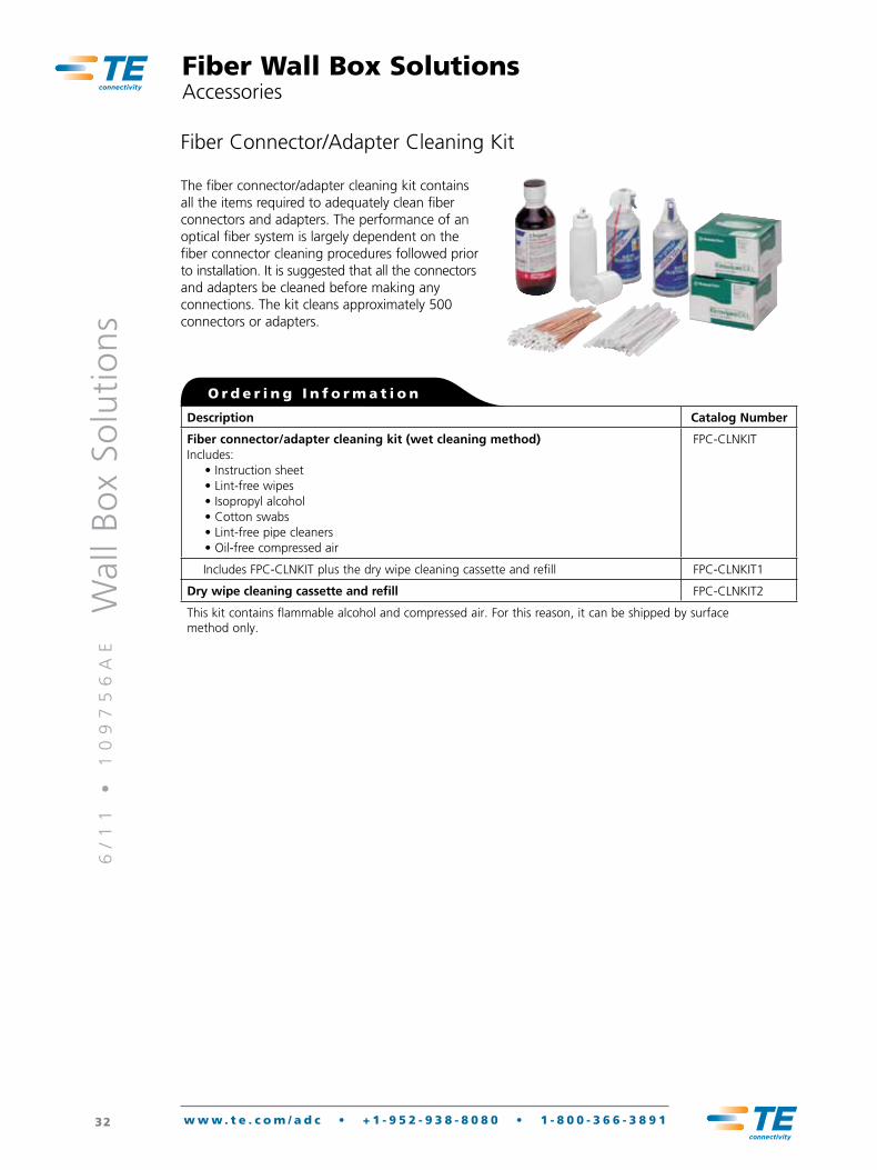
The fiber connector/adapter cleaning kit contains all the items required to adequately clean fiber connectors and adapters. The performance of an optical fiber system is largely dependent on the fiber connector cleaning procedures followed prior to installation. It is suggested that all the connectors and adapters be cleaned before making any connections. The kit cleans approximately 500 connectors or adapters.
Fiber Connector/Adapter Cleaning Kit
Fiber Wall Box SolutionsAccessories
Description Catalog Number
Fiber connector/adapter cleaning kit (wet cleaning method)Includes: • Instruction sheet • Lint-free wipes • Isopropyl alcohol • Cotton swabs • Lint-free pipe cleaners • Oil-free compressed air
FPC-CLNKIT
Includes FPC-CLNKIT plus the dry wipe cleaning cassette and refill FPC-CLNKIT1
Dry wipe cleaning cassette and refill FPC-CLNKIT2
This kit contains flammable alcohol and compressed air. For this reason, it can be shipped by surface method only.
O r d e r i n g I n f o r m a t i o n
6/
11
•
1
09
75
6A
E
Wal
l B
ox
Solu
tio
ns
33 w w w . t e . c o m / a d c • + 1 - 9 5 2 - 9 3 8 - 8 0 8 0 • 1 - 8 0 0 - 3 6 6 - 3 8 9 1
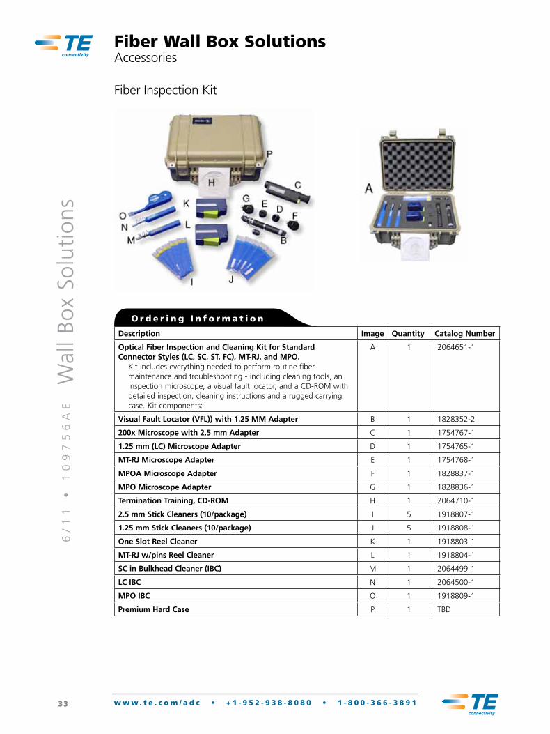
Fiber Inspection Kit
Fiber Wall Box SolutionsAccessories
Description Image Quantity Catalog Number
Optical Fiber Inspection and Cleaning Kit for Standard Connector Styles (LC, SC, ST, FC), MT-RJ, and MPO.
Kit includes everything needed to perform routine fiber maintenance and troubleshooting - including cleaning tools, an inspection microscope, a visual fault locator, and a CD-ROM with detailed inspection, cleaning instructions and a rugged carrying case. Kit components:
A 1 2064651-1
Visual Fault Locator (VFL)) with 1.25 MM Adapter B 1 1828352-2
200x Microscope with 2.5 mm Adapter C 1 1754767-1
1.25 mm (LC) Microscope Adapter D 1 1754765-1
MT-RJ Microscope Adapter E 1 1754768-1
MPOA Microscope Adapter F 1 1828837-1
MPO Microscope Adapter G 1 1828836-1
Termination Training, CD-ROM H 1 2064710-1
2.5 mm Stick Cleaners (10/package) I 5 1918807-1
1.25 mm Stick Cleaners (10/package) J 5 1918808-1
One Slot Reel Cleaner K 1 1918803-1
MT-RJ w/pins Reel Cleaner L 1 1918804-1
SC in Bulkhead Cleaner (IBC) M 1 2064499-1
LC IBC N 1 2064500-1
MPO IBC O 1 1918809-1
Premium Hard Case P 1 TBD
O r d e r i n g I n f o r m a t i o n
6/
11
•
1
09
75
6A
E
Wal
l B
ox
Solu
tio
ns
34 w w w . t e . c o m / a d c • + 1 - 9 5 2 - 9 3 8 - 8 0 8 0 • 1 - 8 0 0 - 3 6 6 - 3 8 9 1
Protective Tubing Cutting ToolThe protective tubing cutting tool is used to score the protective tubing so the tubing can be cut to the appropriate lengths for the final installation.
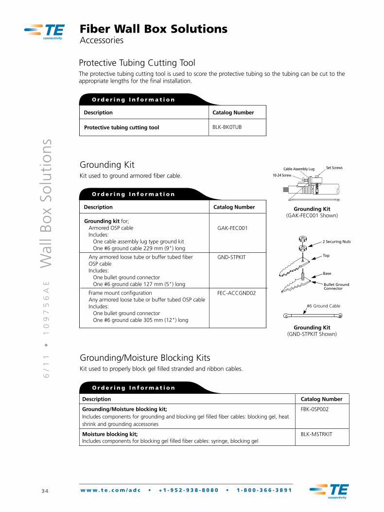
Grounding KitKit used to ground armored fiber cable.
2 Securing Nuts
Top
Base
Bullet GroundConnector
Set Screws
10-24 Screw
Cable Assembly Lug
Grounding kit for; Armored OSP cable
Includes: One cable assembly lug type ground kit One #6 ground cable 229 mm (9") long
Any armored loose tube or buffer tubed fiber OSP cable Includes: One bullet ground connector One #6 ground cable 127 mm (5") long
Frame mount configuration Any armored loose tube or buffer tubed OSP cable Includes: One bullet ground connector One #6 ground cable 305 mm (12") long
Description Catalog Number
GAK-FEC001
GND-STPKIT
FEC-ACCGND02
O r d e r i n g I n f o r m a t i o n
Grounding Kit(GAK-FEC001 Shown)
Grounding Kit(GND-STPKIT Shown)
Protective tubing cutting tool
Description Catalog Number
BLK-BK0TUB
O r d e r i n g I n f o r m a t i o n
#6 Ground Cable
Fiber Wall Box SolutionsAccessories
Grounding/Moisture Blocking KitsKit used to properly block gel filled stranded and ribbon cables.
O r d e r i n g I n f o r m a t i o n
Description Catalog Number
Grounding/Moisture blocking kit; Includes components for grounding and blocking gel filled fiber cables: blocking gel, heat shrink and grounding accessories
FBK-0SP002
Moisture blocking kit; Includes components for blocking gel filled fiber cables: syringe, blocking gel
BLK-MSTRKIT
6/
11
•
1
09
75
6A
E
Wal
l B
ox
Solu
tio
ns
35 w w w . t e . c o m / a d c • + 1 - 9 5 2 - 9 3 8 - 8 0 8 0 • 1 - 8 0 0 - 3 6 6 - 3 8 9 1
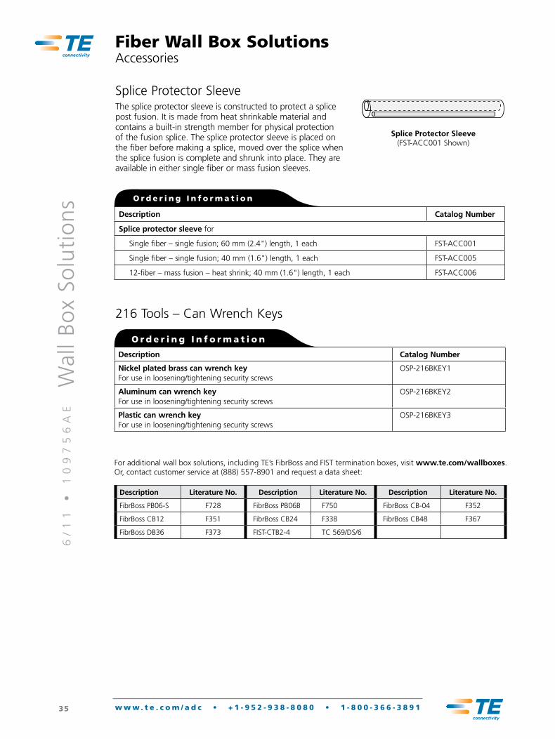
Splice Protector SleeveThe splice protector sleeve is constructed to protect a splice post fusion. It is made from heat shrinkable material and contains a built-in strength member for physical protection of the fusion splice. The splice protector sleeve is placed on the fiber before making a splice, moved over the splice when the splice fusion is complete and shrunk into place. They are available in either single fiber or mass fusion sleeves.
Splice Protector Sleeve(FST-ACC001 Shown)
O r d e r i n g I n f o r m a t i o n
Description Catalog Number
Splice protector sleeve for
Single fiber – single fusion; 60 mm (2.4") length, 1 each FST-ACC001
Single fiber – single fusion; 40 mm (1.6") length, 1 each FST-ACC005
12-fiber – mass fusion – heat shrink; 40 mm (1.6") length, 1 each FST-ACC006
Fiber Wall Box SolutionsAccessories
For additional wall box solutions, including TE’s FibrBoss and FIST termination boxes, visit www.te.com/wallboxes. Or, contact customer service at (888) 557-8901 and request a data sheet:
Description Literature No. Description Literature No. Description Literature No.
FibrBoss PB06-S F728 FibrBoss PB06B F750 FibrBoss CB-04 F352
FibrBoss CB12 F351 FibrBoss CB24 F338 FibrBoss CB48 F367
FibrBoss DB36 F373 FIST-CTB2-4 TC 569/DS/6
216 Tools – Can Wrench Keys
Description Catalog Number
Nickel plated brass can wrench key For use in loosening/tightening security screws
OSP-216BKEY1
Aluminum can wrench key For use in loosening/tightening security screws
OSP-216BKEY2
Plastic can wrench key For use in loosening/tightening security screws
OSP-216BKEY3
O r d e r i n g I n f o r m a t i o n

TE Connectivity Ltd.P.O. Box 1101Minneapolis, Minnesota USA 55440-1101Tel: 1-800-366-3891 Tel: 1-952-938-8080Fax: 1-952-917-3237
www.te.com/adcwww.tycoelectronics.comwww.us.telecomosp.com
TE Connectivity, TE connectivity (logo), Tyco Electronics, TE (logo), ADC, Rapid and RapidReel are trademarks of the TE Connectivity Ltd. family of companies and its licensors. While Tyco Electronics has made every reasonable effort to ensure the accuracy of the information in this document, Tyco Electronics does not guarantee that it is error-free, nor does Tyco Electronics make any other representation, warranty or guarantee that the informa-tion is accurate, correct, reliable or current. Tyco Electronics reserves the right to make any adjustments to the information contained herein at any time without notice. Tyco Electronics expressly disclaims all implied warranties regarding the information contained herein, including, but not limited to, any implied warranties of merchantability or fitness for a particular purpose. The dimensions in this document are for reference purposes only and are subject to change without notice. Specifications are subject to change without notice. Consult Tyco Electronics for the latest dimensions and design specifications.
WA
ll B
ox
So
luti
on
S
ADC is now TE Connectivity
Tyco Electronics Corporation, a TE Connectivity Ltd. Company. All Rights Reserved.109756AE 6/11 Original © 2011