wastewater collection and treatment facilities integrated ... 6 - ch 01 - scada... · wastewater...
TRANSCRIPT
City of Riverside WASTEWATER COLLECTION AND TREATMENT FACILITIES INTEGRATED MASTER PLAN VOLUME 6: SCADA MANAGEMENT PLAN CHAPTER 1: SCADA MANAGEMENT PLAN FINAL February 2008
1 0 5 4 0 T A L B E R T A V E N U E , S U I T E 2 0 0 E A S T • F O U N T A I N V A L L E Y , C A L I F O R N I A 9 2 7 0 8 • ( 7 1 4 ) 5 9 3 - 5 1 0 0 • F A X ( 7 1 4 ) 5 9 3 - 5 1 0 1 H:\Client\Riversid_SAOW\7472A00\Rpt\Volume 06\CH01.doc
City of Riverside
WASTEWATER COLLECTION AND TREATMENT FACILITIES INTEGRATED MASTER PLAN
VOLUME 6: SCADA MANAGEMENT PLAN
CHAPTER 1: SCADA MANAGEMENT PLAN
TABLE OF CONTENTS
Page No. 1.1 PURPOSE.............................................................................................................. 1-1 1.2 CONCLUSIONS AND RECOMMENDATIONS ...................................................... 1-1 1.3 SCADA PLAN OVERVIEW .................................................................................... 1-2 1.4 CHAPTER 1 - HARDWARE ................................................................................... 1-3 1.5 CHAPTER 2 - TERMINAL SERVER ...................................................................... 1-3 1.6 CHAPTER 3 - SCADA (HMI) SOFTWARE ............................................................ 1-4 1.7 CHAPTER 4 - APPLICATION ................................................................................ 1-4 1.8 CHAPTER 5 - HISTORIAN..................................................................................... 1-5 1.9 CHAPTER 6 - COMMUNICATIONS....................................................................... 1-5 1.10 CHAPTER 7 - SCADA PLCS AND RTUS.............................................................. 1-5 1.11 CHAPTER 8 - SECURITY POLICY........................................................................ 1-5 1.12 CHAPTER 9 - ALARM DIALER.............................................................................. 1-6 1.13 CHAPTER 10 - REMOTE ACCESS....................................................................... 1-6 APPENDIX A – CITY OF RIVERSIDE WATER QUALITY CONTROL PLANT SCADA
MASTER PLAN (WATERHAMMER, MARCH 2007)
February 2008 i H:\Client\Riversid_SAOW\7472A00\Rpt\Volume 06\CH01.doc
Chapter 1
SCADA MANAGEMENT PLAN
1.1 PURPOSE WaterHammer, Inc., of Upland, CA, authored a Supervisory Control and Data Acquisition (SCADA) Plan for the City of Riverside (City) Regional Water Quality Control Plant (RWQCP). It primarily covers the existing system and has extensive and fairly detailed descriptions of system hardware and software components. It also includes some standard support recommendations that are generally applicable to all SCADA systems. A copy of the SCADA Plan completed by WaterHammer is included in Appendix A.
The purpose of this document is to review each chapter of the plan, evaluate its content, and discuss the high-priority recommendations made by the author. It will also recommend some additional high-priority analysis.
1.2 CONCLUSIONS AND RECOMMENDATIONS Overall, the SCADA Plan covers the existing system and makes general recommendations for future support. These recommendations are listed in the WaterHammer SCADA Plan in Appendix C. The Plan provides:
• Good descriptions of existing hardware.
• Appropriate analysis and recommendations in these areas: – Hardware redundancy. – Develop standards. – Tag name conventions. – PLCs. – Programming.
• Good, but general recommendations for additional plans, policies, and standards: – Hardware and software disaster recovery plans. – Application standardization. – Application rebuild. – Programming. – Tagging. – Graphics, paging.
With one exception, Carollo Engineers (Carollo) concurs with the WaterHammer recommendations. That exception is the use of an external Keyboard, Video, Mouse (KVM) over Internet Protocol (IP) switch to provide remote operator access. Carollo believes that more study is needed to select and design a remote access method.
February 2008 1-1 H:\Client\Riversid_SAOW\7472A00\Rpt\Volume 06\CH01.doc
However, the Plan is not integrated with other Master Plan documents and does not include planning recommendations or costs for future SCADA expansion to accommodate the RWQCP expansion.
Carollo recommends the following priority enhancements to the existing SCADA Plan that are not currently in Carollo’s scope:
• Integration with other master plan documents discussing their impact on SCADA with cost data.
• Further documentation of the existing system for planning purposes, including network hardware and software components, number of existing tags, operator screens, and reports.
• Analysis of system expansion requirements and capabilities, including the thin-client configuration.
• Further analysis of security. Carollo Engineers recommends a comprehensive SCADA security review and plan.
• Analysis of auxiliary systems critical to SCADA reliability: – HVAC. – Power backup: Generator and Uninterruptible Power Supply (UPS).
• Network design analysis (including a network diagram) and traffic monitoring to determine the network vulnerabilities and capacity for future expansion.
• Analysis of alarm system, including alarm levels, alarm management, and the alarm dialer.
In addition, a business case analysis for SCADA would provide critical data for long-term planning and budgeting by analyzing which SCADA enhancements are most cost-effective. This analysis would include the following:
• Analysis of benefits of integration of IT systems: – Computerized Maintenance Management Systems (CMMS). – Laboratory Information Management Systems (LIMS). – Asset Management. – Accounting and Budget Systems.
1.3 SCADA PLAN OVERVIEW The SCADA Plan is broken into the following chapters:
1. Hardware.
2. Terminal Server.
February 2008 1-2 H:\Client\Riversid_SAOW\7472A00\Rpt\Volume 06\CH01.doc
3. Software.
4. Application (programs).
5. Historian.
6. Communications.
7. PLCs and Remote Terminal Units (RTUs).
8. Security Policy.
9. Alarm Dialer.
10. Remote Access.
11. Portable Units.
1.4 CHAPTER 1 - HARDWARE This chapter describes servers and terminal services. It recommends additional redundancy, including moving the backup server to a remote location, and recommends a replacement cycle plan. The Plan also provides some standard recommendations for review of Human Machine Interface (HMI) requirements prior to ordering new hardware and software, and development of a Hardware Disaster Recovery plan.
The information presented is primarily in list form and needs a SCADA network diagram to show both the network components and the inter-relationships between SCADA components.
1.5 CHAPTER 2 - TERMINAL SERVER This chapter describes the existing terminal services arrangement, which provides HMI operator sessions to users on remote “thin clients.” These are standard personal computers running a minimal installation of Windows using Windows Terminal Services for remote access. It also discusses advantages of using a thin-client configuration for HMI, primarily simplified maintenance. This is because the SCADA application runs only on the servers, not on the remote clients, so there is only one installation of the software to maintain.
There are some areas that need more complete discussion. Although there are no indications that the thin-client-terminal services configuration cannot support the plant expansion, for completeness a discussion of this topic is needed. Typically, this would include a discussion of how many simultaneous clients the server can support and how, and to what extent, this configuration can be expanded as the plant grows. It would also be useful to compare terminal services to other alternatives, with regard to security, reliability, redundancy, expandability, and impact on network traffic.
February 2008 1-3 H:\Client\Riversid_SAOW\7472A00\Rpt\Volume 06\CH01.doc
1.6 CHAPTER 3 - SCADA (HMI) SOFTWARE This chapter describes the existing SCADA HMI Wonderware InTouch® software by listing the components. It recommends that an upgrade policy and a software disaster recovery plan be established, and gives some basic criteria.
The presentation does not discuss the functions and capabilities of the software and does not compare these with the client’s business needs, or discuss any software limitations. There is no discussion of the corporate background of the supplier, the availability of support, or the cost of licenses and maintenance agreements. Support requirements, including personnel, training, upgrades, and configuration maintenance, are not covered.
1.7 CHAPTER 4 - APPLICATION The chapter provides a good overview of the SCADA application software. It recommends establishing programming standards for graphics, navigation, controls and security, and upgrading existing applications to standards. It also recommends establishing a tag name standard and an application rebuild policy. The discussion does not document the number of tags and screens, which is needed to estimate the cost of the upgrades.
It also recommends that programming and controls for the tertiary plant be moved from the SCADA application to PLC. However, based on discussions with the plant staff, this was limited to some non-critical operator menu selections, and this change has already been implemented.
HMI standards are a high priority, and should be established in workshops during the design phase and incorporated into the design documents.
The plan recommends that a tag name convention list be established. This list will include the desired new tag name convention as well as the current convention used for different areas of the plant. This should also be established in workshops during the design phase.
The plan recommends that regular and automatic reports be established and suggests the possible use of reports in process analysis and equipment maintenance. It does not discuss the feasibility or advantages of developing integrated reporting with other applications such as the California Integrated Water Quality System (CIWQS) or LIMS. One commonly used strategy for implementing reports is for the specifications to require the systems integrator to develop a quantity of reports, with the complexity level specified in number of variables, number of pages, etc. The reports are then defined further in workshops with the systems integrator during the programming phase.
February 2008 1-4 H:\Client\Riversid_SAOW\7472A00\Rpt\Volume 06\CH01.doc
1.8 CHAPTER 5 - HISTORIAN The Plan describes the Wonderware Industrial Sequential Query Language (SQL) historian configuration and redundancy, and recommends additional data backup, including off-site storage and a networked Redundant Array of Independent Drives (RAID) hard drive.
1.9 CHAPTER 6 - COMMUNICATIONS This chapter discusses the various communications protocols running on the SCADA network, including Transfer Control Protocol/Internet Protocol (TCP/IP), Modbus®, Modbus Plus®, Modbus/TCP®, and SyEnet protocols. TCP/IP over Ethernet is used for communications between the SCADA servers to the remote thin clients.
The Plan recommends changing the cogeneration PLCs to Modicon PLCs, replacing the TDS32 protocol with Modbus/TCP®, implementing communications alarms, developing a backup communication method to the lift stations, and replacing Intrac RTUs with Moscad RTUs.
The communications presentation lacks the following components:
• Network diagram.
• Network component inventory and analysis.
• Traffic analysis and discussion of impact of multiple protocols.
• Analysis of network redundancy.
• Future network expansion plans.
• Analysis and discussion of existing radio communications, including reliability, security, and expandability.
1.10 CHAPTER 7 - SCADA PLCS AND RTUS The Plan lists the types of PLCs and RTUs currently used within the plant, including Modicon Quantum and Square D PLCs, Motorola Intrac, and Moscad RTUs. The author recommends standardizing on Modicon PLCs and Modbus/TCP® protocol.
1.11 CHAPTER 8 - SECURITY POLICY This section is brief and generic and does not present, analyze, or discuss existing security policies. It recommends development of a written security policy, listing specific areas, such as physical access, passwords, user logins, and software update procedures, but does not include a needs analysis. Many areas listed are only indirectly related to security and should be covered under a reliability analysis, including backup power, power conditioning
February 2008 1-5 H:\Client\Riversid_SAOW\7472A00\Rpt\Volume 06\CH01.doc
alarms, and air conditioning alarms. The following additional analysis and discussions are needed:
• Analysis of existing security.
• Needs analysis.
• Homeland Security requirements.
• Risk analysis.
• Analysis of possible encryption of wireless SCADA links.
1.12 CHAPTER 9 - ALARM DIALER This section describes the remote alarm notification for the SCADA system. This consists of SCADAlarm, a software application owned by Wonderware, which runs in parallel with the HMI application. SCADAlarm provides a remote telephone dialer and a local annunciator. The alarms on the existing SCADAlarm/dialer are not consistent with the InTouch® software alarms and the report recommends a complete review of the existing plant alarms.
There is no discussion of alarm levels or alarm management, which are important to standardize in order to reduce the number of nuisance alarms. In addition, consideration should be given to a backup hardware alarm dialer, which will operate in the case of a software failure, for remote operator notification of critical alarms.
1.13 CHAPTER 10 - REMOTE ACCESS The author recommends using an external KVM over IP switch. A KVM switch is a hardware device that allows a user to control multiple computers from a single keyboard, video monitor, and mouse.
This method is generally used for single-user remote server support (the discussion mentions administrative functions, such as rebooting servers) and it is unclear how this would work for remote operator access to the HMI. There are security concerns with many implementations of this technology. There is no evaluation or comparison of alternatives commonly used to provide remote access, such as software-based and web services. It may be an acceptable solution, but in general, a remote access method should not be chosen without a needs analysis, including consideration of the following:
• Number of simultaneous remote users.
• Functional needs of remote users, such as access to all or just high-priority alarms, access to graphics screens, user security levels, reports, and trending.
• Security – encryption and access validation.
• Security maintenance.
February 2008 1-6 H:\Client\Riversid_SAOW\7472A00\Rpt\Volume 06\CH01.doc
• Remote access hardware and software maintenance and support requirements.
• Communications services costs and reliability.
• Bandwidth required and available.
February 2008 1-7 H:\Client\Riversid_SAOW\7472A00\Rpt\Volume 06\CH01.doc
Appendix A CITY OF RIVERSIDE WATER QUALITY CONTROL PLANT SCADA MASTER PLAN (WATERHAMMER, MARCH 2007)
February 2008 A-1 H:\Client\Riversid_SAOW\7472A00\Rpt\Volume 06\CH01.doc
0
City of Riverside Water Quality Control Plant SCADA Master Plan
March, 2007
Submitted by: WaterHammer, Inc. * 1906 N. Wilson Ave. * Upland, CA 91784 * (909) 985-7293
City of Riverside Water Quality Control Plant, SCADA Master Plan - 2007
Table of Contents SCADA Master Plan Executive Summary Chapter 1: SCADA Hardware 1.1 Overview 1.2 Servers 1.2.1 Terminal Servers 1.2.2 InSQL Servers 1.2.3 IO Servers 1.2.4 System Backup Server 1.3 Hardware Redundancy 1.4 Replacement Cycle Plan 1.5 Hardware Requirements and Standardization 1.6 Hardware Disaster Recovery Plan Chapter 2: Terminal Server 2.1 Overview 2.2 Thin Client configuration 2.3 User setup Chapter 3: SCADA Software 3.1 Overview 3.2 Server Software
3.3 Upgrade Policy 3.4 Disaster Recovery Plan ` Chapter 4: Application 4.1 Overview
4.2 Programming Standardization 4.3 Application Standardization 4.4 Application Rebuild Policy 4.5 Tagname Convention 4.6 MBEnet / MPPlus Failover 4.7 I/O server connectivity 4.8 Tertiary Programming 4.9 Trending 4.10 Automatic and Demand-driven reporting
Chapter 5: Historian 5.1 Overview 5.2 InSQL Functionality 5.3 Data Backup
Submitted by: WaterHammer, Inc. * 1906 N. Wilson Ave. * Upland, CA 91784 * (909) 985-7293
2
City of Riverside Water Quality Control Plant, SCADA Master Plan - 2007
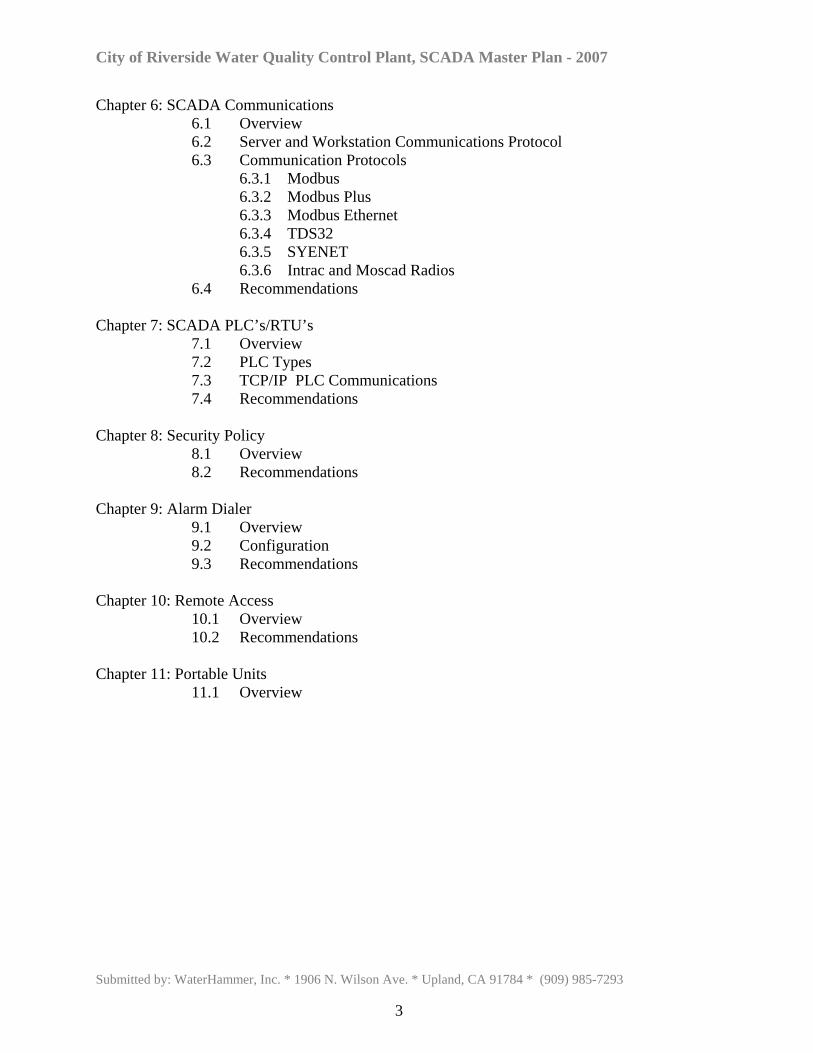
Chapter 6: SCADA Communications 6.1 Overview 6.2 Server and Workstation Communications Protocol 6.3 Communication Protocols 6.3.1 Modbus 6.3.2 Modbus Plus 6.3.3 Modbus Ethernet 6.3.4 TDS32
6.3.5 SYENET 6.3.6 Intrac and Moscad Radios
6.4 Recommendations Chapter 7: SCADA PLC’s/RTU’s 7.1 Overview 7.2 PLC Types 7.3 TCP/IP PLC Communications
7.4 Recommendations Chapter 8: Security Policy 8.1 Overview 8.2 Recommendations Chapter 9: Alarm Dialer 9.1 Overview 9.2 Configuration 9.3 Recommendations Chapter 10: Remote Access 10.1 Overview 10.2 Recommendations Chapter 11: Portable Units 11.1 Overview
Submitted by: WaterHammer, Inc. * 1906 N. Wilson Ave. * Upland, CA 91784 * (909) 985-7293
3
City of Riverside Water Quality Control Plant, SCADA Master Plan - 2007
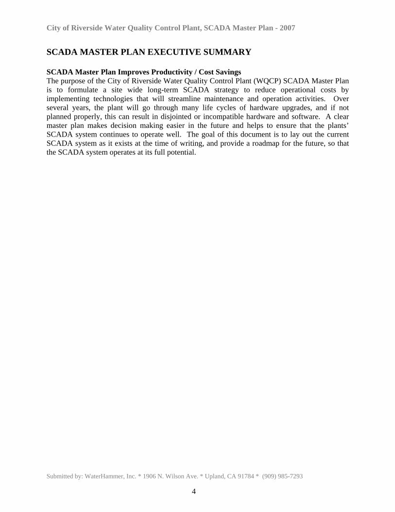
SCADA MASTER PLAN EXECUTIVE SUMMARY SCADA Master Plan Improves Productivity / Cost Savings The purpose of the City of Riverside Water Quality Control Plant (WQCP) SCADA Master Plan is to formulate a site wide long-term SCADA strategy to reduce operational costs by implementing technologies that will streamline maintenance and operation activities. Over several years, the plant will go through many life cycles of hardware upgrades, and if not planned properly, this can result in disjointed or incompatible hardware and software. A clear master plan makes decision making easier in the future and helps to ensure that the plants’ SCADA system continues to operate well. The goal of this document is to lay out the current SCADA system as it exists at the time of writing, and provide a roadmap for the future, so that the SCADA system operates at its full potential.
Submitted by: WaterHammer, Inc. * 1906 N. Wilson Ave. * Upland, CA 91784 * (909) 985-7293
4
City of Riverside Water Quality Control Plant, SCADA Master Plan - 2007
Chapter 1
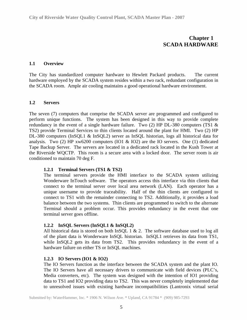
SCADA HARDWARE 1.1 Overview The City has standardized computer hardware to Hewlett Packard products. The current hardware employed by the SCADA system resides within a two rack, redundant configuration in the SCADA room. Ample air cooling maintains a good operational hardware environment. 1.2 Servers The seven (7) computers that comprise the SCADA server are programmed and configured to perform unique functions. The system has been designed in this way to provide complete redundancy in the event of a single hardware failure. Two (2) HP DL-380 computers (TS1 & TS2) provide Terminal Services to thin clients located around the plant for HMI. Two (2) HP DL-380 computers (InSQL1 & InSQL2) server as InSQL historian, logs all historical data for analysis. Two (2) HP xw6200 computers (IO1 & IO2) are the IO servers. One (1) dedicated Tape Backup Server. The servers are located in a dedicated rack located in the Kush Tower at the Riverside WQCTP. This room is a secure area with a locked door. The server room is air conditioned to maintain 70 deg F.
1.2.1 Terminal Servers (TS1 & TS2) The terminal servers provide the HMI interface to the SCADA system utilizing Wonderware InTouch software. The operators access this interface via thin clients that connect to the terminal server over local area network (LAN). Each operator has a unique username to provide traceability. Half of the thin clients are configured to connect to TS1 with the remainder connecting to TS2. Additionally, it provides a load balance between the two systems. Thin clients are programmed to switch to the alternate Terminal should a problem occur. This provides redundancy in the event that one terminal server goes offline. 1.2.2 InSQL Servers (InSQL1 & InSQL2) All historical data is stored on both InSQL 1 & 2. The software database used to log all of the plant data is Wonderware InSQL historian. InSQL1 retrieves its data from TS1, while InSQL2 gets its data from TS2. This provides redundancy in the event of a hardware failure on either TS or InSQL machines. 1.2.3 IO Servers (IO1 & IO2) The IO Servers function as the interface between the SCADA system and the plant IO. The IO Servers have all necessary drivers to communicate with field devices (PLC’s, Media converters, etc). The system was designed with the intention of IO1 providing data to TS1 and IO2 providing data to TS2. This was never completely implemented due to unresolved issues with existing hardware incompatibilities (Lantronix virtual serial
Submitted by: WaterHammer, Inc. * 1906 N. Wilson Ave. * Upland, CA 91784 * (909) 985-7293
5
City of Riverside Water Quality Control Plant, SCADA Master Plan - 2007
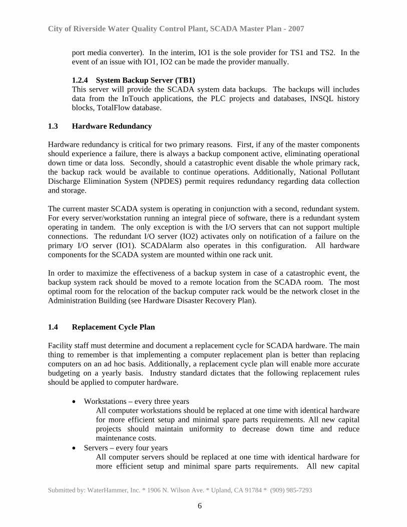
port media converter). In the interim, IO1 is the sole provider for TS1 and TS2. In the event of an issue with IO1, IO2 can be made the provider manually. 1.2.4 System Backup Server (TB1) This server will provide the SCADA system data backups. The backups will includes data from the InTouch applications, the PLC projects and databases, INSQL history blocks, TotalFlow database.
1.3 Hardware Redundancy Hardware redundancy is critical for two primary reasons. First, if any of the master components should experience a failure, there is always a backup component active, eliminating operational down time or data loss. Secondly, should a catastrophic event disable the whole primary rack, the backup rack would be available to continue operations. Additionally, National Pollutant Discharge Elimination System (NPDES) permit requires redundancy regarding data collection and storage. The current master SCADA system is operating in conjunction with a second, redundant system. For every server/workstation running an integral piece of software, there is a redundant system operating in tandem. The only exception is with the I/O servers that can not support multiple connections. The redundant I/O server (IO2) activates only on notification of a failure on the primary I/O server (IO1). SCADAlarm also operates in this configuration. All hardware components for the SCADA system are mounted within one rack unit. In order to maximize the effectiveness of a backup system in case of a catastrophic event, the backup system rack should be moved to a remote location from the SCADA room. The most optimal room for the relocation of the backup computer rack would be the network closet in the Administration Building (see Hardware Disaster Recovery Plan). 1.4 Replacement Cycle Plan
Facility staff must determine and document a replacement cycle for SCADA hardware. The main thing to remember is that implementing a computer replacement plan is better than replacing computers on an ad hoc basis. Additionally, a replacement cycle plan will enable more accurate budgeting on a yearly basis. Industry standard dictates that the following replacement rules should be applied to computer hardware.
• Workstations – every three years All computer workstations should be replaced at one time with identical hardware for more efficient setup and minimal spare parts requirements. All new capital projects should maintain uniformity to decrease down time and reduce maintenance costs.
• Servers – every four years All computer servers should be replaced at one time with identical hardware for more efficient setup and minimal spare parts requirements. All new capital
Submitted by: WaterHammer, Inc. * 1906 N. Wilson Ave. * Upland, CA 91784 * (909) 985-7293
6
City of Riverside Water Quality Control Plant, SCADA Master Plan - 2007
projects should maintain uniformity to decrease down time and reduce maintenance costs.
1.5 Hardware Requirements and Standardization Based on the hardware replacement cycle plan, new hardware will be purchased on a scheduled basis. With ever-changing electronic enhancements and OS development, it is critical to review the HMI software operating requirements prior to ordering new systems. Wonderware continuously updates the minimum system requirements and compatibility lists. Configurations may need to be altered over time based on industry changes. In order to minimize maintenance and down time, identical systems should be purchased whenever possible. Changes with I/O drivers and hardware over time may eliminate the need for work stations to run the I/O driver software in the future. 1.6 Hardware Disaster Recovery Plan A Disaster Recovery Plan must be established and documented in order to ensure a swift and effortless operational transition in the event of a major catastrophe. The following criteria should be determined and followed in case of a hardware malfunction.
• Determine and document the procedures for responding to a disaster that involves the
SCADA center and its services. A disaster is defined as the occurrence of any event that causes a significant disruption in SCADA capabilities.
• Acquire additional hardware for disaster recovery plan or move current backup hardware to a different location.
• Determine a method for periodic testing of disaster recovery plan.
Submitted by: WaterHammer, Inc. * 1906 N. Wilson Ave. * Upland, CA 91784 * (909) 985-7293
7
City of Riverside Water Quality Control Plant, SCADA Master Plan - 2007
Chapter 2
TERMINAL SERVER 2.1 Overview The City utilizes a terminal server for operations access to the SCADA system. This configuration was implemented due to the numerous locations that required multiple stations in the field. Originally, individual PC’s or Servers existed throughout the plant, but maintenance and management was highly inefficient and operation was very problematic. This new platform provides access from virtually anywhere in the plant with minimal hardware and implementation effort using thin client units. 2.2 Thin Client Configuration Currently, there are approximately twenty-five thin clients in use throughout the WQCP Plant. These units are used by operations, maintenance, electrical, SCADA staff and administration. Each thin client is either pointing to terminal server 1 or 2 for access to the SCADA application. Several key operational areas of the plant have multiple clients. At these locations where two thin clients exist side by side, each will be pointing to a different terminal server to assist in balancing the Terminal server client loading and to have instantaneous client connection in the event of a Terminal Server failure. The thin clients are configured with a primary source Terminal Server and a secondary Terminal Server. On boot up or malfunction, the thin client will try to access the primary Terminal Server to source information. If it is not able to connect to the primary terminal server, it will proceed to load from the secondary terminal server identified. In order to equalize the load on the terminal servers, new thin clients should be added to the server with the less clients defined. 2.3 User Setup Thin clients are configured to log on as a user and boot up directly into the Wonderware application. Based on security level, some additional applications may be available via access buttons on the application. Additionally, each thin client is operating under Network Application Deployment.(NAD) architecture. The master copy of the SCADA application exists in TS1 and TS2. Each thin client runs a copy of the main application in a supervisory defined location
Submitted by: WaterHammer, Inc. * 1906 N. Wilson Ave. * Upland, CA 91784 * (909) 985-7293
8
City of Riverside Water Quality Control Plant, SCADA Master Plan - 2007
Chapter 3
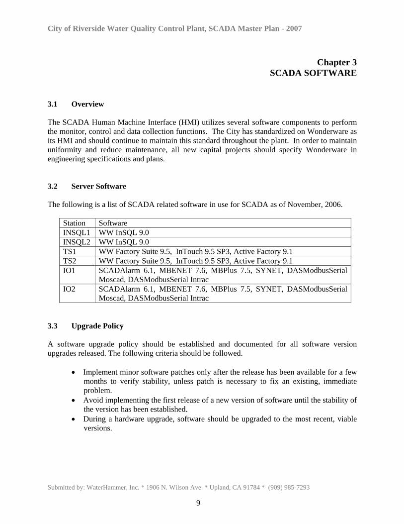
SCADA SOFTWARE 3.1 Overview The SCADA Human Machine Interface (HMI) utilizes several software components to perform the monitor, control and data collection functions. The City has standardized on Wonderware as its HMI and should continue to maintain this standard throughout the plant. In order to maintain uniformity and reduce maintenance, all new capital projects should specify Wonderware in engineering specifications and plans. 3.2 Server Software The following is a list of SCADA related software in use for SCADA as of November, 2006.
Station Software INSQL1 WW InSQL 9.0 INSQL2 WW InSQL 9.0 TS1 WW Factory Suite 9.5, InTouch 9.5 SP3, Active Factory 9.1 TS2 WW Factory Suite 9.5, InTouch 9.5 SP3, Active Factory 9.1 IO1 SCADAlarm 6.1, MBENET 7.6, MBPlus 7.5, SYNET, DASModbusSerial
Moscad, DASModbusSerial Intrac IO2 SCADAlarm 6.1, MBENET 7.6, MBPlus 7.5, SYNET, DASModbusSerial
Moscad, DASModbusSerial Intrac 3.3 Upgrade Policy A software upgrade policy should be established and documented for all software version upgrades released. The following criteria should be followed.
• Implement minor software patches only after the release has been available for a few months to verify stability, unless patch is necessary to fix an existing, immediate problem.
• Avoid implementing the first release of a new version of software until the stability of the version has been established.
• During a hardware upgrade, software should be upgraded to the most recent, viable versions.
Submitted by: WaterHammer, Inc. * 1906 N. Wilson Ave. * Upland, CA 91784 * (909) 985-7293
9
City of Riverside Water Quality Control Plant, SCADA Master Plan - 2007
3.4 Software Disaster Recovery Plan A disaster recovery plan must be established and documented in order to ensure minimal operational and data loss in the event of a major catastrophe. The following criteria should be determined and followed in case of a software malfunction.
• Determine ways to recover from any type of loss including historical data, installation media, application files, configuration files, documents, and software licenses.
• Determine a method for keeping the system up-to-date. • Decide what steps to take to restore onsite media and information to its previous state
in the event of a disaster. • Create a centralized inventory of all software titles and licenses. Store copies in a
fireproof, waterproof, lockable cabinet. • Perform regular system back ups and send copies of backup files to a SAN (storage
array network) offsite.
Submitted by: WaterHammer, Inc. * 1906 N. Wilson Ave. * Upland, CA 91784 * (909) 985-7293
10
City of Riverside Water Quality Control Plant, SCADA Master Plan - 2007
Chapter 4
APPLICATION 4.1 Overview The current SCADA application is derived from the integration of multiple applications created for different processes in the plant. Historically, each process consisted of the development of its own application programmed by various vendors. Additionally, each process or location utilized either one or two PCs, some operating in a “master backup” configuration. Over time, these applications were integrated into several master applications. The systems were running different versions of the application, different versions of the HMI software, different operating system versions and different hardware platforms. This collage resulted in a continuous state of maintenance and support. The 2005 upgrade to Intouch for Terminal Services eliminated the need for multiple redundant PC’s and time consuming application maintenance. The SCADA application resides on Terminal Servers 1 and 2 and are running the same application version. Application development is done on a stand alone development system. New application work is then deployed to TS2 for testing and observation. On acceptance, the new application version is deployed to TS1. After an application change, thin clients are prompted to restart for an application reload. 4.2 Programming Standardization Since the various process applications were created by multiple programmers, inconsistencies exist with policies in screen appearance, navigation, objects, control functions, and alarm displays. In order to make the application cohesive and easily extensible, standardization for graphic screens, navigation, controls, and security is required. Additionally, standardization will benefit new operations personnel in coming up to speed and minimize any operational errors due to application inconsistencies. SCADA personnel must work with operations to determine and document standardization protocols for each of the areas identified below. A preliminary list of criteria is also included.
• Screens – size, back ground color, basic layout • Navigation – menu bars, navigation buttons, locations, sizes, colors
• Controls – method, control objects, control scripting
• Objects – pumps, wells, motors, value display, setpoint display, pipes, etc. • Log In – screen, access, options • Color – operational colors, warnings, alarms, alarm ack., alarm cleared,
Submitted by: WaterHammer, Inc. * 1906 N. Wilson Ave. * Upland, CA 91784 * (909) 985-7293
11
City of Riverside Water Quality Control Plant, SCADA Master Plan - 2007
4.3 Application Standardization Based on the history and state of the current application, it is recommended that the application be updated to include the documented application standards. All existing screens should be modified to reflect these standards. And all new capital improvements with HMI graphics should be developed based on the standards. 4.4 Application Rebuild Policy Due to the large size of the SCADA application, the possibility of application corruption increases. Application corruption may not be evident during regular operation, but can become problematic behind the scenes and cause unexplained system malfunctions and instability. It is recommended that the application be rebuilt on each of these scenarios.
• minimum once a year • following any major application work
4.5 Tagname Convention SCADA application design personnel will identify and document a Tagname Convention List. This list should include the desired new tagname convention as well as the current convention used for different areas of the plant. This list will help operations identify tags necessary for historical review. Due to the size of the current tagname database, renaming existing tags is not required. 4.6 MBEnet/MBPlus Failover Currently, the City utilizes both MBEnet and MBPlus protocols. In the past, failover programming would activate should the primary I/O communication path go down. This programming was unreliable and questionable in operation. With the new configuration, it is recommended that a new failover program be designed and implemented to make full use of the communications available while improving reliability.
Submitted by: WaterHammer, Inc. * 1906 N. Wilson Ave. * Upland, CA 91784 * (909) 985-7293
12
City of Riverside Water Quality Control Plant, SCADA Master Plan - 2007
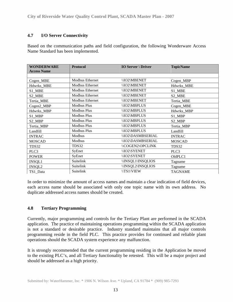
4.7 I/O Server Connectivity Based on the communication paths and field configuration, the following Wonderware Access Name Standard has been implemented. WONDERWARE Access Name
Protocol IO Server \ Driver TopicName
Cogen_MBE Modbus Ethernet \\IO2\MBENET Cogen_MBP Hdwrks_MBE Modbus Ethernet \\IO2\MBENET Hdwrks_MBE S1_MBE Modbus Ethernet \\IO2\MBENET S1_MBE S2_MBE Modbus Ethernet \\IO2\MBENET S2_MBE Tertia_MBE Modbus Ethernet \\IO2\MBENET Tertia_MBE Cogen2_MBP Modbus Plus \\IO2\MBPLUS Cogen_MBE Hdwrks_MBP Modbus Plus \\IO2\MBPLUS Hdwrks_MBP S1_MBP Modbus Plus \\IO2\MBPLUS S1_MBP S2_MBP Modbus Plus \\IO2\MBPLUS S2_MBP Tertia_MBP Modbus Plus \\IO2\MBPLUS Tertia_MBP Landfill Modbus Plus \\IO2\MBPLUS Landfill INTRAC Modbus \\IO2\DASMBSERIAL INTRAC MOSCAD Modbus \\IO2\DASMBSERIAL MOSCAD TDS32 TDS32 \\COGEN2\OPCLINK TDS32 PLC3 SyEnet \\IO2\SYENET PLC3 POWER SyEnet \\IO2\SYENET OldPLC1 INSQL1 Suitelink \\INSQL1\INSQLIOS Tagname INSQL2 Suitelink \\INSQL2\INSQLIOS Tagname TS1_Data Suitelink \\TS1\VIEW TAGNAME
In order to minimize the amount of access names and maintain a clear indication of field devices, each access name should be associated with only one topic name with its own address. No duplicate addressed access names should be created. 4.8 Tertiary Programming Currently, major programming and controls for the Tertiary Plant are performed in the SCADA application. The practice of maintaining operations programming within the SCADA application is not a standard or desirable practice. Industry standard maintains that all major controls programming reside in the field PLC. This practice provides for continued and reliable plant operations should the SCADA system experience any malfunction. It is strongly recommended that the current programming residing in the Application be moved to the existing PLC’s, and all Tertiary functionality be retested. This will be a major project and should be addressed as a high priority.
Submitted by: WaterHammer, Inc. * 1906 N. Wilson Ave. * Upland, CA 91784 * (909) 985-7293
13
City of Riverside Water Quality Control Plant, SCADA Master Plan - 2007
4.9 Trending The historical trend functionality currently in use utilizes WONDERWARE Active Factory software. This application uses Active X objects embedded in the SCADA application. Trend data is gathered from either InSQL Servers. Additionally, the existing application uses the original HisData application to display live data on multiple screens. 4.10 Automatic and Demand-Driven Reporting Efficiency and performance of any process is a high priority for any plant operation. Daily, weekly, monthly and yearly reporting can identify multiple aspects of plant performance and operation. Utilization of the reporting functions available with the SCADA system can greatly increase efficiency and identify problematic areas in need of attention. Comparative analysis of reports can identify possible decline of equipment performance or malfunction. Additionally, regulatory data can be easily compiled and evaluated. The Active Factory reporting function pulls data from InSQL and utilizes MS Excel to create any reporting requirements. It is recommended that regular automatic reports be established for data, field and process analysis. Access to Excel and calculator is available on screen via a button which allows operations personnel the ability to create reports in order to more effectively operate their particular site.
Submitted by: WaterHammer, Inc. * 1906 N. Wilson Ave. * Upland, CA 91784 * (909) 985-7293
14
City of Riverside Water Quality Control Plant, SCADA Master Plan - 2007
Chapter 5
HISTORIAN 5.1 Overview The City SCADA System utilizes Wonderware IndustrialSQL (InSQL) in conjunction with Microsoft SQL to collect and maintain historical data from the field and periphery. The primary function for the Historian is to ensure compliance with NPDES permit for data collection. The openness of the SQL-based interface offers high-performance storage and data compression capabilities. With InSQL, operations receive improved data analysis and information sharing with advanced trending and reporting capabilities. Additionally, InSQL provides robust high-security communication capabilities for data integrity and dependable data delivery. 5.2 InSQL Functionality Both InSQL1 and InSQL2 are loaded with InSQL 9.0 with 25,000 tag licenses. Each unit is collecting data from TS1, TS2 and IO1. Data collection from IO1 will automatically switch to IO2 should IO1 experience any technical difficulties. All system and user defined tagnames in InTouch are collecting data within InSQL. Currently, field I/O is collected directly from the I/O drivers including MBENET, MBPlus, SYNET, and DAS servers. Additionally, system, internal and memory tags from the master application on TS1 and TS2 are simultaneously collected as well. Data is stored locally on each server creating a redundant data collection/storage scenario. Trends and reports can be created via Active Factory by selecting either INSQL1 or INSQL2 as the data provider. Storage capacity for the servers allows multiple years of data to be stored locally on each server. 5.3 Data Backup Regardless of the ability of the servers to store large quantities of historical data in a redundant fashion, an additional, remote data storage device method should be identified and implemented as the ‘off site’ data storage. There are many possible solutions to this data backup issue. Staff has procured a Tape Backup system that will be installed and then further develop a tape backup strategy. However, a networked RAID hard drive will provide ease of use and accessibility compared to other storage media.
Submitted by: WaterHammer, Inc. * 1906 N. Wilson Ave. * Upland, CA 91784 * (909) 985-7293
15

City of Riverside Water Quality Control Plant, SCADA Master Plan - 2007
Chapter 6
Communications 6.1 Overview Several communication protocols are in use at the plant. Computers communicate over TCP/IP. PLC’s and RTU’s communicate over Modbus, Modbus Plus, Modbus Ethernet and SYENET protocols. 6.2 Server and Workstation Communication Protocols
TCP/IP The SCADA servers and thin clients communicate via TCP/IP protocol over Gigabit Ethernet twisted pair (LAN). Each device on the LAN is assigned a permanent fixed IP address. This LAN is completely separate from the City of Riverside LAN and other networks (Internet) for security reasons. The following table does not include the IP addresses duw to security easons.
Description Location Subnet INSQL1 Server Room 255.255.255.0 INSQL2 Server Room 255.255.255.0 TS1 Server Room 255.255.255.0 TS2 Server Room 255.255.255.0 IO1 Server Room 255.255.255.0 IO2 Server Room 255.255.255.0 TB1 Server Room 255.255.255.0 MCP S1 Building 255.255.255.0 LCP1 Blower Building 255.255.255.0 LCP2 Blower Building 255.255.255.0 LCP3 Blower Building 255.255.255.0 LCP4 Blower Building 255.255.255.0 LCP5 Blower Building 255.255.255.0
6.3 PLC and RTU Communication Protocols
The following communication protocols are use to communicate between the IO servers and the plant PLC’s or field RTU’s. The use of these protocols is identified in a table under the application section.
6.3.1 Modbus A serial protocol that has become an industry de facto standard for PLC communications. However, this protocol has specific limitations associated to serial devices such as speed and connection limits. Modbus is used to communicate to the Motorola RTU- Field
Submitted by: WaterHammer, Inc. * 1906 N. Wilson Ave. * Upland, CA 91784 * (909) 985-7293
16
City of Riverside Water Quality Control Plant, SCADA Master Plan - 2007
Interface Unit (FIU). The FIU in turn communicates to the Intrac and Moscad RTU’s at the various lift station sites. 6.3.2 Modbus Plus An asynchronous protocol where embedded Modbus messages are transmitted over an RS485 link. This token passing protocol is supported by fiber to RS485 devices manufactured by Weed Instruments. This communication path is configured in a ring where the media converters generate an artificial break in the fiber ring whereas in the event of an actual fiber break the media converter will remove the virtual break while communication is maintained. Modbus Plus is used as a backup communications path to the Modbus Ethernet.. This method provides a redundant PLC communication protocol and path in the event that the Modbus Ethernet link fails. The drawback to this protocol is the cost for Modbus Plus network switches, specialized communication cards, diagnostics and speed. 6.3.3 Modbus Ethernet A protocol where Modbus is embedded within TCP frames. Ethernet is the primary communication path between the Modicon PLC’s and the SCADA System. The Modicon PLC’s have dedicated IP addresses. All primary plant processes utilize Modicon PLC’s configured for hot standby. The repair of Plant S1 panel did not include replacing the redundant PLC. Additionally, these Modicon PLC’s are using RIO Head/Drop modules. 6.3.4 TDS32 TDS32 is a unique protocol used for the Cogen ABB gas monitoring equipment. 6.3.5 SYENET The SyEnet protocol is used to communicate to one Square D PLC. The SyEnet driver is bound to the Ethernet adapter card. The existing communications to these PLC’s use 10Mb half duplex. The network switch ports must also be locked at this link speed and duplex mode. 6.3.6 Intrac and Moscad Lift stations including Pierce Road & Wood Road communicate over Motorola radios to the Field Interface Unit (FIU) located at Cogen. The antenna for the radio is mounted on top of the Cogen building. The protocol used for the RTU’s is dependent on the RTU type.
6.4 Recommendations
In order to streamline and simplify communications within the plant, the following recommendations should be implemented.
Submitted by: WaterHammer, Inc. * 1906 N. Wilson Ave. * Upland, CA 91784 * (909) 985-7293
17

City of Riverside Water Quality Control Plant, SCADA Master Plan - 2007
• Move the TDS 32 communications driver and supporting software from the old SCADA PC to IO Servers 1 & 2.
• Develop a backup communication method to the Lift Stations. • Develop a project to replace Intrac RTU’s with Moscad RTU’s • Update PLC processors at Cogen to support Modbus TCP. • Create communication alarms in InTouch application for every distinct
communication path from the IO server to the PLC/RTU to augment IO Server failover upon communication path failure.
Submitted by: WaterHammer, Inc. * 1906 N. Wilson Ave. * Upland, CA 91784 * (909) 985-7293
18
City of Riverside Water Quality Control Plant, SCADA Master Plan - 2007
Chapter 7
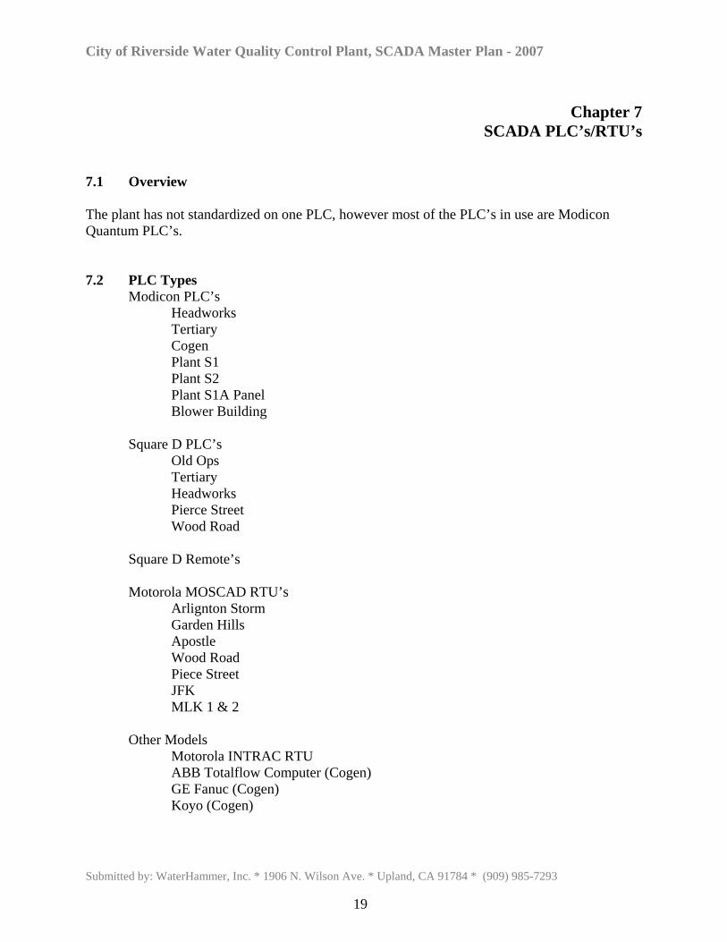
SCADA PLC’s/RTU’s 7.1 Overview The plant has not standardized on one PLC, however most of the PLC’s in use are Modicon Quantum PLC’s. 7.2 PLC Types Modicon PLC’s Headworks Tertiary Cogen Plant S1 Plant S2 Plant S1A Panel Blower Building Square D PLC’s Old Ops Tertiary Headworks Pierce Street Wood Road Square D Remote’s Motorola MOSCAD RTU’s Arlignton Storm Garden Hills Apostle Wood Road Piece Street JFK MLK 1 & 2 Other Models Motorola INTRAC RTU ABB Totalflow Computer (Cogen) GE Fanuc (Cogen) Koyo (Cogen)
Submitted by: WaterHammer, Inc. * 1906 N. Wilson Ave. * Upland, CA 91784 * (909) 985-7293
19
City of Riverside Water Quality Control Plant, SCADA Master Plan - 2007
7.3 TCP/IP PLC Communications
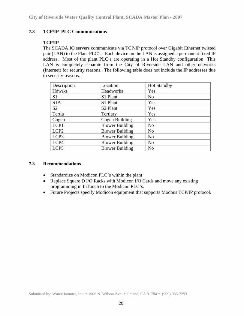
TCP/IP The SCADA IO servers communicate via TCP/IP protocol over Gigabit Ethernet twisted pair (LAN) to the Plant PLC’s. Each device on the LAN is assigned a permanent fixed IP address. Most of the plant PLC’s are operating in a Hot Standby configuration This LAN is completely separate from the City of Riverside LAN and other networks (Internet) for security reasons. The following table does not include the IP addresses due to security reasons.
Description Location Hot Standby Hdwrks Headworks Yes S1 S1 Plant No S1A S1 Plant Yes S2 S2 Plant Yes Tertia Tertiary Yes Cogen Cogen Building Yes LCP1 Blower Building No LCP2 Blower Building No LCP3 Blower Building No LCP4 Blower Building No LCP5 Blower Building No
7.3 Recommendations
• Standardize on Modicon PLC’s within the plant • Replace Square D I/O Racks with Modicon I/O Cards and move any existing
programming in InTouch to the Modicon PLC’s. • Future Projects specify Modicon equipment that supports Modbus TCP/IP protocol.
Submitted by: WaterHammer, Inc. * 1906 N. Wilson Ave. * Upland, CA 91784 * (909) 985-7293
20
City of Riverside Water Quality Control Plant, SCADA Master Plan - 2007
Chapter 8
Security Policy 8.1 Overview Security policies are a set of rules and business practices that define how an organization will be safe. A security policy with respect to computer systems includes location, locks, logins, alarms, environmental conditions, system update procedures, data backups, system backups, disaster recovery, These policies will determine the level of constraints that are imposed on casual users, operators and administrators. 8.2 Recommendations A written security policy should be developed that at a minimum includes:
• Physical access to server room. • Administrator passwords. • User logins and strength level. • Application development procedures. • Application testing procedures. • Application backup procedures. • Software update procedures • The time between the release date of a new software version before installation. • System, data and emergency backups and frequency. • Testing frequency of restoring system and data files. • PC, PLC and network hardware spares. • Backup power and power conditioning alarms. • Air conditioning alarms
Submitted by: WaterHammer, Inc. * 1906 N. Wilson Ave. * Upland, CA 91784 * (909) 985-7293
21
City of Riverside Water Quality Control Plant, SCADA Master Plan - 2007
Chapter 9
ALARM DIALER 9.1 Overview Remote alarm notification for the SCADA system is performed by SCADAlarm, an advanced local enunciator and remote telephonic dialer. 9.2 Configuration Redundant SCADAlarm modems are implemented and operate on a failover configuration. Critical and important alarms are programmed within the software package and are activated via Wonderware Suitelink protocol to the Wonderware Application. When a critical alarm activates in Window Viewer, notification is sent to SCADAlarm. SCADAlarm will then begin local annunciation at preprogrammed intervals. Additionally, a text message is sent to the operations pager for a response. When an alarm is acknowledged it is logged, including the person who acknowledged the alarm. The City has employed SCADA monitoring personnel to acknowledge alarms and notify various process operators of an alarm as an additional form of advisement. 9.3 Recommendations The current alarms programmed in SCADAlarm are not consistent with existing InTouch alarms. It is recommended that a complete review of the existing plant alarms be completed. From this review a list can be generated for the alarms and programming for SCADAlarm. After SCADAlarm is updated then a review of the possible alarms can be reviewed with operations. It is recommended that all plant alarms be included within SCADAlarm and then after the review with operations alarms that are not required can then be disabled via the graphical interface. This approach will guarantee that an alarm that is not require today for current use within operations will be available if and when needed with a single mouse click.
Submitted by: WaterHammer, Inc. * 1906 N. Wilson Ave. * Upland, CA 91784 * (909) 985-7293
22
City of Riverside Water Quality Control Plant, SCADA Master Plan - 2007
Chapter 10
REMOTE ACCESS 10.1 Overview Remote Access allows SCADA administrators and field service personnel to control and monitor the SCADA System from a remote location. Originally, SCADA was accessed locally using VNC as the interface. PCAnywhere was also available to Cogen operators for remote access. With the advent of Terminal Server and from a security standpoint, these methods are not viable. 10.2 Recommendation A viable and secure option for remote access is to utilize an external KVM over IP switch. KVM switches via IP technology allows users to control and access multiple computers from a single keyboard, monitor and mouse remotely. Administrators can control, reset and reboot servers in a datacenter from a remote location and even watch the entire boot process remotely.
KVM over IP switches allow control from any web browser, eliminating the need for proprietary client access software, saving thousands of dollars in per user licensing fees. Security is assured for your sensitive data using several security mechanisms.
It is recommended that a remote access solution be implemented to minimize response time should a problem or question occur. Remote access should be available for management, operations, maintenance, and SCADA support.
Submitted by: WaterHammer, Inc. * 1906 N. Wilson Ave. * Upland, CA 91784 * (909) 985-7293
23
City of Riverside Water Quality Control Plant, SCADA Master Plan - 2007
Chapter 11
PORTABLE UNITS 11.1 Overview Due to the terminal server architecture of the SCADA system, remote, portable units could easily be implemented. Access to SCADA at lift stations with fiber or radio communications could also be deployed thus enabling electrical personnel to visualize field modifications and status while at a remote location. The same would be true for plant personnel to utilize remote units via fiber or wireless radio throughout the plant. There are several different footprints for portable units. Cell phones, PDA’s, laptops, notebooks and tablets all qualify as portable and all have a possibility to be linked into the SCADA system. However, there are advantages and disadvantages to all portable types that need to be reviewed before adding portable access into the SCADA systems.
Submitted by: WaterHammer, Inc. * 1906 N. Wilson Ave. * Upland, CA 91784 * (909) 985-7293
24