week12: interface via labview€¦ · web...
TRANSCRIPT
523372_Embedded Systems_4(3-3-9)Week01: Arduino BasicWeek02: Arduino Shield Week03: LabView Interface from Arduino via VISA
บทนำ�
ก�รทดลองก�รทดลองท่ี 0/3: LabVIEW Introduction
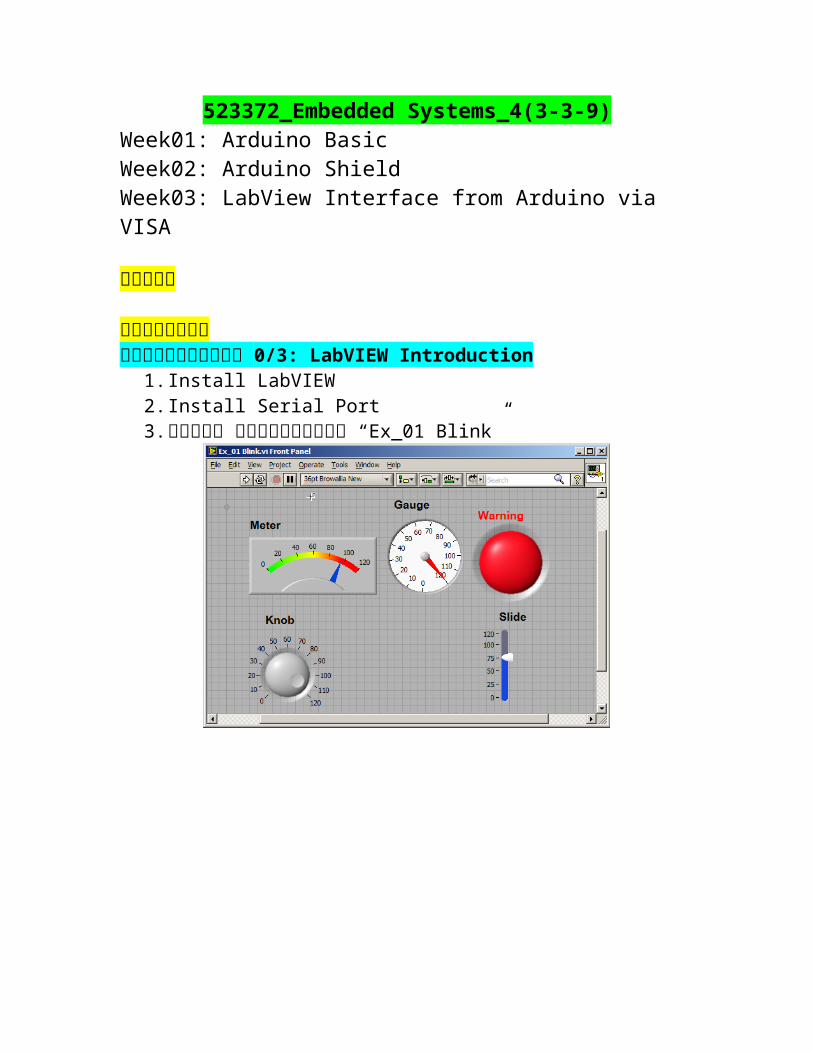
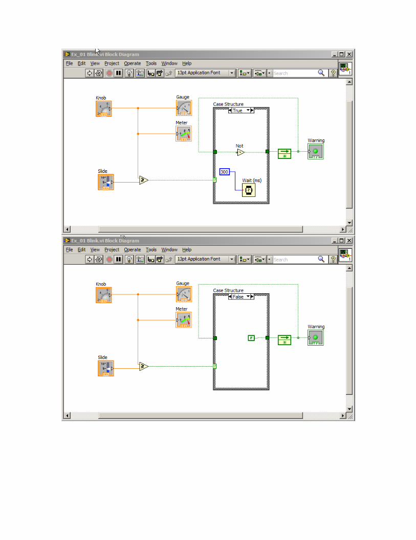
1. Install LabVIEW 2. Install Serial Port3. ทดสอบ รนัโปรแกรม “Ex_01 Blink”
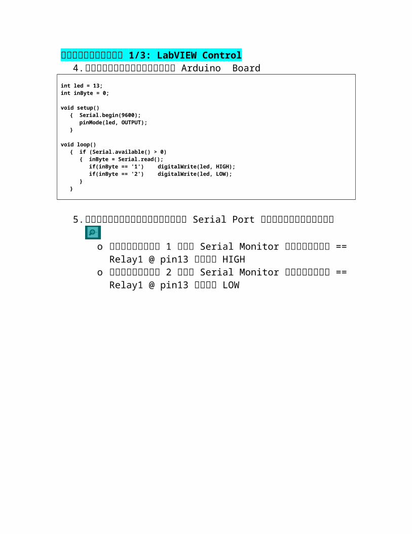
ก�รทดลองท่ี 1/3: LabVIEW Control4. โหลดโปรแกรมไปยงั Arduino Board
int led = 13;int inByte = 0;
void setup() { Serial.begin(9600);
pinMode(led, OUTPUT);}
void loop(){ if (Serial.available() > 0)
{ inByte = Serial.read();if(inByte == '1') digitalWrite(led, HIGH);if(inByte == '2') digitalWrite(led, LOW);
}}
5. ทดสอบการควบคมุผ่าน Serial Port โดยเปิดใชง้าน o การสง่เลข 1 ท่ี Serial Monitor จะทำาให ้== Relay1 @
pin13 เป็น HIGHo การสง่เลข 2 ท่ี Serial Monitor จะทำาให ้== Relay1 @
pin13 เป็น LOW
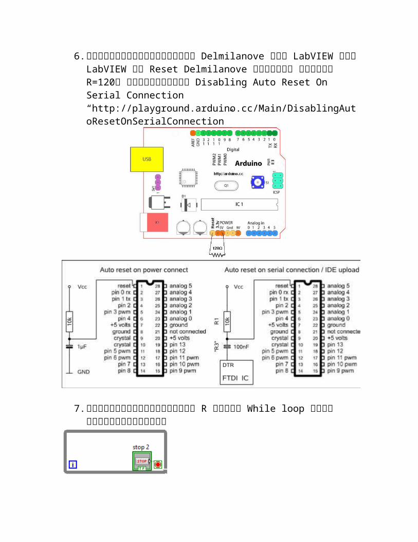
6. การใชง้านบอรด์กลุ่ม Delmilanove กับ LabVIEW ตัว LabVIEW จะ Reset Delmilanove ทกุๆรอบ จงึต่อ R=120 เพื่อทำาการ Disabling Auto Reset On Serial Connection “http://playground.arduino.cc/Main/DisablingAutoResetOnSerialConnection”
7. กรณีไมต้่องการเพิม่ R จะใช ้While loop ครอบโปรแกรมทัง้หมด

8. ทดสอบการควบคมุผ่าน LabVIEW ด้วยโปรแกรม “Ex_02 Control”
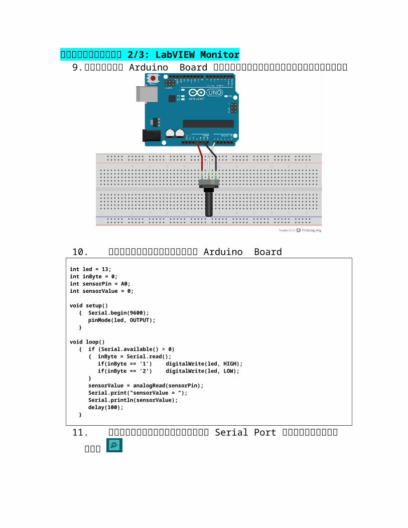
ก�รทดลองท่ี 2/3: LabVIEW Monitor9. ต่อวงจร Arduino Board กับความต้านทานปรบัค่าได้
10. โหลดโปรแกรมไปยงั Arduino Boardint led = 13;int inByte = 0; int sensorPin = A0;int sensorValue = 0;
void setup() { Serial.begin(9600);
pinMode(led, OUTPUT);}
void loop(){ if (Serial.available() > 0)
{ inByte = Serial.read();if(inByte == '1') digitalWrite(led, HIGH);if(inByte == '2') digitalWrite(led, LOW);
}sensorValue = analogRead(sensorPin);Serial.print("sensorValue = ");Serial.println(sensorValue);delay(100);
}
11. ทดสอบการควบคมุผ่าน Serial Port โดยเปิดใชง้าน o ปรบัค่าความต้านทานปรบัค่าได้ จะทำาใหค้่ามกีารเปล่ียนแปลงo การสง่เลข 1 ท่ี Serial Monitor จะทำาให ้== Relay1 @
pin13 เป็น HIGH
o การสง่เลข 2 ท่ี Serial Monitor จะทำาให ้== Relay1 @ pin13 เป็น LOW

12. ทดสอบการอ่านค่าผ่าน LabVIEW ด้วยโปรแกรม “Ex_03 Monitor”
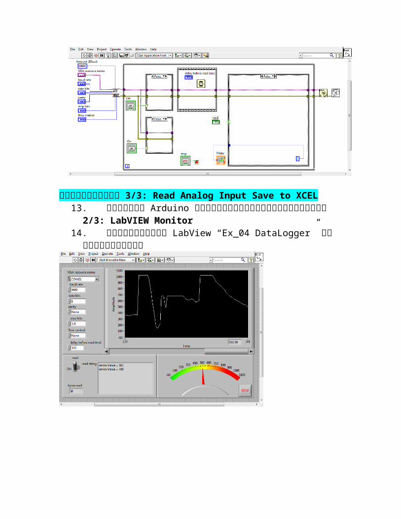
ก�รทดลองท่ี 3/3: Read Analog Input Save to XCEL13. ต่อวงจร Arduino และโปรแกรมตามก�รทดลองท่ี 2/3:
LabVIEW Monitor14. เปิดโปรแกรม LabView “Ex_04 DataLogger” ดผูลการ
ทำางาน

คำาถามท้ายการทดลองJob1/3: Relay Control 2 Relay- จาก LabVIEW control 1 Relay {ON-1 OFF-1}- ใหป้รบัแก้เป็น LabVIEW control 2 Relay {ON-1 OFF-1 ON-
2 OFF-2}- แนะนำาให ้สง่ ‘ 1’ Relay1 On, ‘2’ Relay1 Off, ‘3’ Relay2
On, ‘4’ Relay2 Off
Job2/3: Counter Display on LabVIEW- Arduino นับการกด PB Switch ทัง้ 2 ตัว- การนับต้อง Save ไวท้ี่ EPROM เมื่อไฟดับขอ้มูลต้องไมห่าย- สง่ผลท่ีนับได้แสดงท่ี LabVIEW
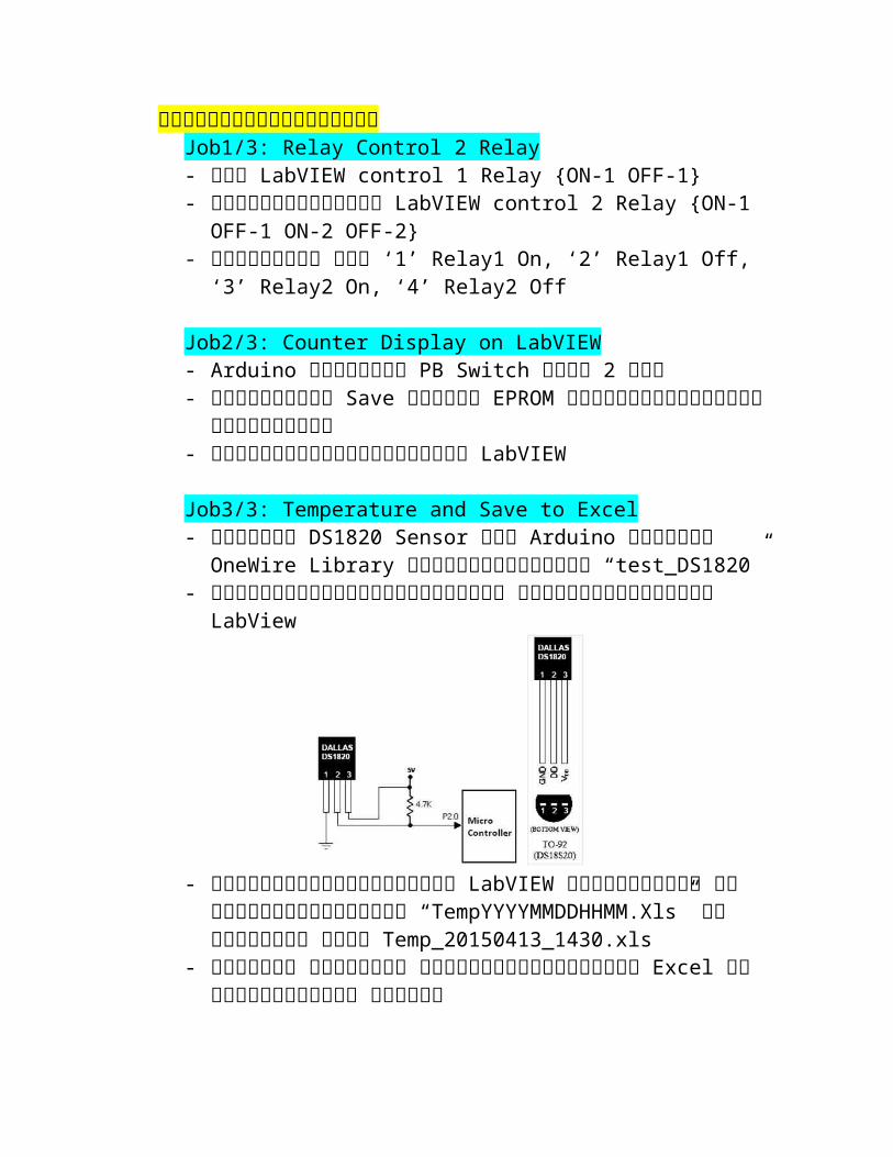
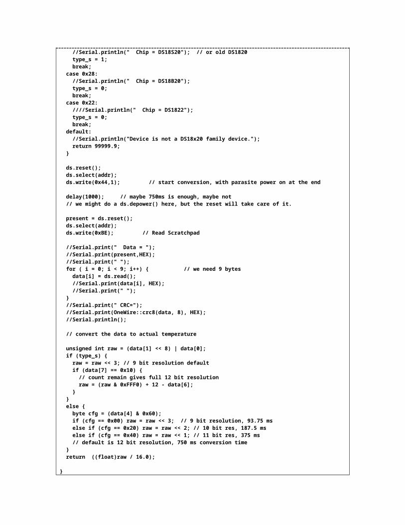
Job3/3: Temperature and Save to Excel- ต่อวงจร DS1820 Sensor กับ Arduino ติดตัง้ OneWire Library
และทดสอบโปรแกรม “test_DS1820”- ปรบัแก้โปรแกรมใหเ้หมาะสม เพื่อสง่ค่าไปยงั LabView
- ทกุครัง้เมื่อโปรแกรม LabVIEW เริม่ทำางาน จะตัง้ชื่อไฟล์เป็น “TempYYYYMMDDHHMM.Xls” ยกตัวอยา่ง เชน่ Temp_20150413_1430.xls
- อ่านค่า อุณหภมู ิแล้วบนัทึกขอ้มูลใน Excel ในคอลัมภ์ต่างๆ ดังนี้
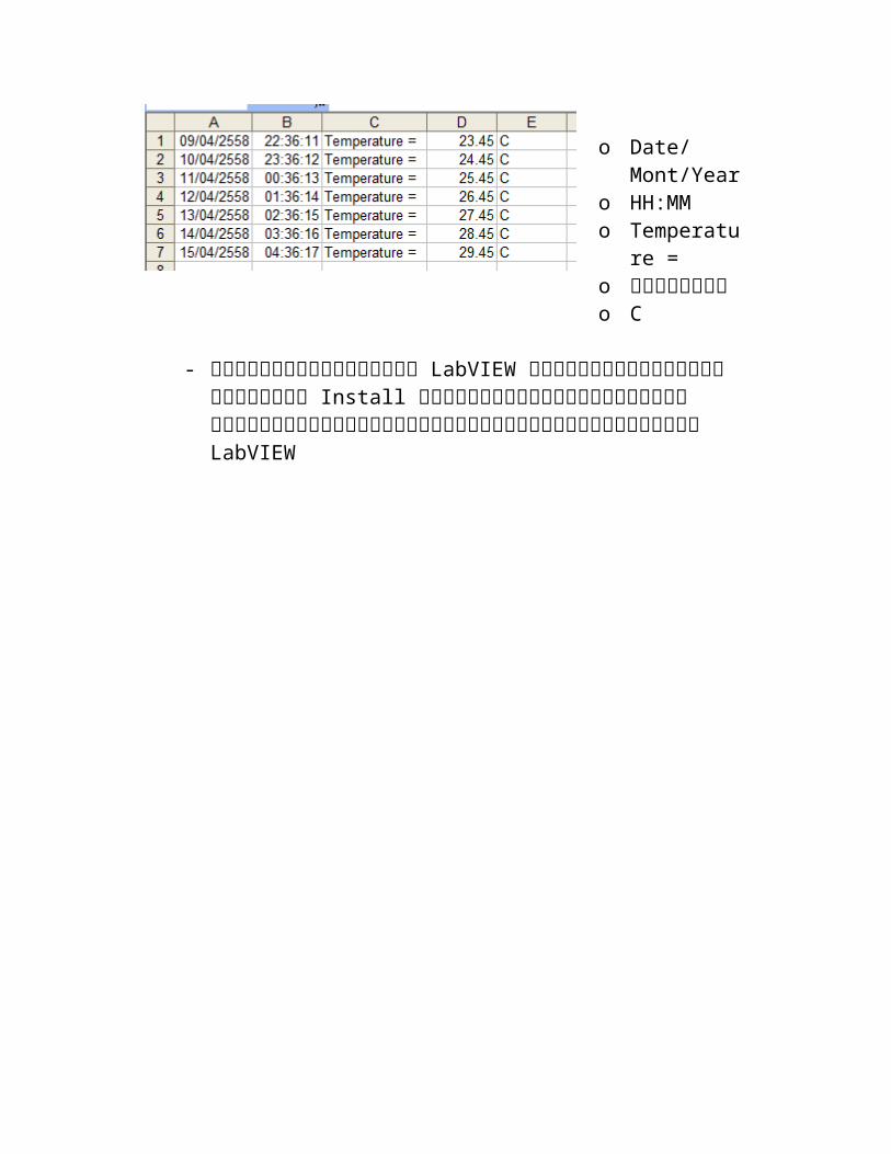
o Date/Mont/Year
o HH:MMo Temperatu
re = o อุณหภมู ิo C
- เมื่อสรา้งโปรแกรม LabVIEW เรยีบรอ้ยแล้วให ้สรา้งตัว Install สำาหรบันำาไปติดตัง้ท่ีเครื่องคอมพวิเตอรอ่ื์นที่ไมไ่ด้ลงโปรแกรม LabVIEW

โปรแกรมทดสอบ// test_DS1820#include <OneWire.h>float celsius, fahrenheit;
OneWire ds(10); // on pin 10
void setup(void) { Serial.begin(9600);}
void loop(void) { celsius = ReadTempDS1820(); if (celsius!=99999.9) { fahrenheit = celsius * 1.8 + 32.0; Serial.print(" Temperature = "); Serial.print(celsius); Serial.print(" Celsius, "); Serial.print(fahrenheit); Serial.println(" Fahrenheit"); }}
float ReadTempDS1820(void)
{ byte i; byte present = 0; byte type_s; byte data[12]; byte addr[8]; float celsius, fahrenheit;
if ( !ds.search(addr)) { //Serial.println("No more addresses."); //Serial.println(); ds.reset_search(); delay(250); return 99999.9; }
//Serial.print("ROM ="); for( i = 0; i < 8; i++) { //Serial.write(' '); //Serial.print(addr[i], HEX); }
if (OneWire::crc8(addr, 7) != addr[7]) { //Serial.println("CRC is not valid!"); return 99999.9; } //Serial.println();
// the first ROM byte indicates which chip switch (addr[0]) { case 0x10: //Serial.println(" Chip = DS18S20"); // or old DS1820 type_s = 1; break; case 0x28: //Serial.println(" Chip = DS18B20"); type_s = 0; break; case 0x22: ////Serial.println(" Chip = DS1822"); type_s = 0;
break; default: //Serial.println("Device is not a DS18x20 family device."); return 99999.9; }
ds.reset(); ds.select(addr); ds.write(0x44,1); // start conversion, with parasite power on at the end
delay(1000); // maybe 750ms is enough, maybe not // we might do a ds.depower() here, but the reset will take care of it.
present = ds.reset(); ds.select(addr); ds.write(0xBE); // Read Scratchpad
//Serial.print(" Data = "); //Serial.print(present,HEX); //Serial.print(" "); for ( i = 0; i < 9; i++) { // we need 9 bytes data[i] = ds.read(); //Serial.print(data[i], HEX); //Serial.print(" "); } //Serial.print(" CRC="); //Serial.print(OneWire::crc8(data, 8), HEX); //Serial.println();
// convert the data to actual temperature
unsigned int raw = (data[1] << 8) | data[0]; if (type_s) { raw = raw << 3; // 9 bit resolution default if (data[7] == 0x10) { // count remain gives full 12 bit resolution raw = (raw & 0xFFF0) + 12 - data[6]; } } else { byte cfg = (data[4] & 0x60); if (cfg == 0x00) raw = raw << 3; // 9 bit resolution, 93.75 ms else if (cfg == 0x20) raw = raw << 2; // 10 bit res, 187.5 ms else if (cfg == 0x40) raw = raw << 1; // 11 bit res, 375 ms // default is 12 bit resolution, 750 ms conversion time } return ((float)raw / 16.0);
}